Embed Size (px)
Citation preview
21664 | Phys. Chem. Chem. Phys., 2015, 17, 21664--21682 This journal is© the Owner Societies 2015
Cite this:Phys.Chem.Chem.Phys.,
2015, 17, 21664
Local environments of boron heteroatoms innon-crystalline layered borosilicates†
Mounesha N. Garaga,a Ming-Feng Hsieh,b Zalfa Nour,a Michael Deschamps,a
Dominique Massiot,a Bradley F. Chmelkab and Sylvian Cadars‡*a
Boron heteroatom distributions are shown to be significantly different in two closely related layered
borosilicates synthesized with subtly different alkylammonium surfactant species. The complicated order
and disorder near framework boron sites in both borosilicates were characterized at the molecular level by
using a combination of multi-dimensional solid-state nuclear magnetic resonance (NMR) spectroscopy
techniques and first-principles calculations. Specifically, two-dimensional (2D) solid-state J-mediated
(through-bond) 11B{29Si} NMR analyses provide direct and local information on framework boron sites that
are covalently bonded to silicon sites through bridging oxygen atoms. The resolution and identification of
correlated signals from distinct 11B–O–29Si site pairs reveal distinct distributions of boron heteroatoms in
layered borosilicate frameworks synthesized with the different C16H33N+Me3 and C16H33N+Me2Et structure-
directing surfactant species. The analyses establish that boron atoms are distributed non-selectively among
different types of silicon sites in the layered C16H33N+Me3-directed borosilicate framework, whereas boron
atoms are preferentially incorporated into incompletely condensed Q3-type sites in the C16H33N+Me2Et-
directed borosilicate material. Interestingly, framework boron species appear to induce framework conden-
sation of their next-nearest-neighbor silicon sites in the C16H33N+Me3-directed borosilicate. By comparison,
the incorporation of boron atoms is found to preserve the topology of the C16H33N+Me2Et-directed boro-
silicate frameworks. The differences in boron site distributions and local boron-induced structural transfor-
mations for the two surfactant-directed borosilicates appear to be due to different extents of cross-linking
of the siliceous frameworks. The molecular-level insights are supported by density functional theory (DFT)
calculations, which show the distinct influences of boron atoms on the C16H33N+Me3- and C16H33N+Me2Et-
directed borosilicate frameworks, consistent with the experimental observations.
1. Introduction
Porous materials, such as silica and zeolites, have attractedsignificant attention over the past decades, because of theirdiverse properties that have been exploited in numerous indus-trial applications, including as ion exchangers,1–3 adsorbents,4–6
separation membranes,7,8 or heterogeneous catalysts.9–11 Theseapplications substantially rely on properties that are oftenattributed to the presence of heteroatoms (e.g., Al, B, Ga) insilica- or silicate frameworks. Consequently, understanding theinfluences of the type, quantity, and distributions of heteroatomsin siliceous frameworks is expected to aid improvements in theproperties of such materials.12–14 This has been a major chal-lenge, in part because characterization of heteroatoms siting isdifficult. Even in porous materials with well-ordered structures,such as zeolites, it is challenging to identify the locations ofheteroatoms in their frameworks, as diffraction methods tendto provide predominantly average long-range order, except forsome types of heavy heteroatoms (e.g., Fe or Ti).15–17 Diffractiondata of sufficiently good quality (typically using synchrotron
a CNRS, CEMHTI UPR3079, Universite d’Orleans, F-45071 Orleans, Franceb Department of Chemical Engineering, University of California, Santa Barbara,
California 93106, USA
† Electronic supplementary information (ESI) available: Two-dimensionalthrough-bond-mediated 29Si–29Si correlation spectra (Fig. S1). Estimations ofthe range of the perturbation induced by B incorporation (Table S1). Transversedephasing time measurements (Fig. S2). Model borosilicate structures usingsurfactant-mimicking alkylammonium molecules for the charge balance (Fig. S3).Comparisons between experimental and calculated 29Si chemical shifts (Fig. S4).Summary of 11B chemical shift calculations conducted for models of the C16H33N+Me3-and C16H33N+Me2Et-directed borosilicates with surfactant-mimicking molecules(Tables S2 and S3, respectively). DFT-optimized models of the reference C16H33N+Me2Et-directed silicate material and corresponding calculations of 29Si chemical shifts(Fig. S5). Illustration of the procedure used to build a borosilicate model with twoadditional Si–O–Si connectivities (Fig. S6). Description of pseudo-potentials usedin DFT calculations (Table S4). Calculated shielding and experimental chemicalshifts of reference compounds of known crystal structure (Table S5). Correlationplots between experimental chemical shifts and calculated shielding (11B and 29Si)of known structure (Fig. S7). See DOI: 10.1039/c5cp03448e‡ Present address: Institut des Materiaux Jean Rouxel (IMN), UMR6502, Univer-site de Nantes, CNRS, 2 rue de la Houssiniere, BP32229, 44322 Nantes cedex 3,France. E-mail: [email protected]
Received 15th June 2015,Accepted 13th July 2015
DOI: 10.1039/c5cp03448e
www.rsc.org/pccp
PCCP
PAPER
Publ
ishe
d on
15
July
201
5. D
ownl
oade
d by
Uni
vers
ity o
f C
alif
orni
a -
Sant
a B
arba
ra o
n 13
/08/
2015
19:
55:1
9.
View Article OnlineView Journal | View Issue

This journal is© the Owner Societies 2015 Phys. Chem. Chem. Phys., 2015, 17, 21664--21682 | 21665
X-rays and/or neutrons on highly-crystalline powders or onsingle crystals) may provide average mixed compositions forall crystallographic sites in the favorable cases where structurefactors between the heteroatom and Si are different (e.g., Fe18
or Ga,19,20 but not for Al21). Although this is typically true forboron, the degree of crystallinity and/or the amount of incorpo-rated heteroatoms is in many cases nevertheless insufficient toobtain a reliable refinement of mixed site compositions, especiallyin the case of layered materials with stacking disorder. And evenwhen the overall siting can be obtained with a good accuracy, thisonly corresponds to a long-range average that provides no infor-mation on the short-range ordering and the local structuraldistortions that can result from the presence of these heteroatomsin the framework.22,23
Solid-state nuclear magnetic resonance (NMR) spectroscopyis sensitive to the local environments of heteroatoms and theirdistributions in heteroatom-containing silicates, although thelimited resolution of one-dimensional (1D) NMR spectra hasoften led to ambiguous results.24,25 Previous investigations havesuggested near-random19 or relatively unselective distributionsof heteroatoms in zeolite frameworks.12,25–29 Zeolites with three-dimensional (3D) structures are composed of four-coordinate Sior heteroatom sites (abbreviated as T-sites for tetrahedral) thatare bonded to four other T-sites via bridging oxygen atoms,which lead to solid-state 29Si NMR signals that are designated asQ4 29Si species. (The Qn notation describes bonding configura-tions of T-sites, where n refers to the number of connectedT-sites for a given T-site.) Incompletely condensed Q3 29Si sitesare in general only present in zeolites in the form of defects, withthe exception of a few zeolites where ordered (intrinsic) vacan-cies have recently been revealed.30,31 In siliceous zeolites with 3Dcrystalline order, subtle differences in Si–O–Si bond angles andlengths lead to 29Si signals that can be resolved from crystallo-graphically distinct T-site environments. However, heteroatomsinserted into these Q4 29Si sites appear to result in 29Si NMRsignals that are difficult to resolve, making it challenging todetermine the locations of heteroatoms in the frameworks. Inrare cases, heteroatoms are incorporated into specific frameworksites (e.g., B in the borosilicate zeolite MCM-7032 and layeredborosilicate RUB-39,33 Al21,34 or Ga35 in natrolite-type zeolites),leading to resolved 29Si NMR signals. However, heteroatoms aremore typically incorporated into silicate frameworks withoutdetectable extents of long-range order, leading to broad signalsthat provide little information on the distinct local heteroatomenvironments or their distributions.
In contrast to most zeolites, the ordered 2D frameworks oflayered silicates contain incompletely condensed Q3 29Si frame-work moieties that are generally intrinsic to their structure, inaddition to fully condensed Q4 sites.36–45 Such Q3 and Q4 29Sispecies yield 29Si NMR signals over different frequency ranges:ca. �92 to �103 ppm and ca. �105 to �120 ppm, respectively.Among different types of layered silicates, surfactant-directedlayered silicates46,47 provide several different types of Q3 and Q4
29Si framework sites into which heteroatoms can be incorporatedand potentially distinguished. Here, we focus on surfactant-directed layered silicates that are synthesized in the presence
of cationic alkylammonium surfactants CH3(CH2)15N+Me3 orCH3(CH2)15N+Me2Et, where Me = –CH3 and Et = –C2H5;46 thesedifferent surfactant head groups lead to siliceous frameworkswith different structures containing one Q3 site and one Q4 29Si siteor two Q3 and three Q4 29Si species, respectively. Furthermore, solid-state 29Si NMR signals for these two layered silicate materialsare well resolved and expected to facilitate characterization ofdistributions of heteroatoms incorporated into their frameworks.Al heteroatoms have previously been incorporated in theC16H33N+Me3 – directed layered silicate material, which led tothe creation within the framework of acidic sites whose loca-tion could not be clearly established from standard 1D NMRmeasurements.48,49 In this work we investigate the intercalation ofB heteroatoms into both CH3(CH2)15N+Me3 or CH3(CH2)15N+Me2Et-directed borosilicate. The weaker acidity of incorporated B ascompared to Al heteroatoms opens the way to a modulation ofthe acid catalytic properties for reactions requiring mild acidic solidcatalysts.50,51 In addition, borosilicate zeolites are post-syntheticallymodified by isomorphic substitution of B by other heteroatoms toprepare zeolites that are difficult to synthesize directly.52,53
Among the main strengths of NMR spectroscopy is the ability tounambiguously establish the existence of chemical bonds, whichare probed through indirect spin–spin couplings between nuclei,also referred to as J couplings. Reviews on the methods to probeand use these couplings in solids have been published.54,55 Theyhave been used for many years in zeolites, layered and other typesof silica(tes) materials to probe Si–O–Si46,47,56–59 or Si–O–Al60–62
connectivities in the form of through-bond mediated two-dimensional correlation experiments or spin-counting experi-ments.61 In addition to shedding light on local frameworktopologies, this is extremely valuable information, particularlywhen combined with molecular modeling (at the density func-tional level of theory, DFT), to assist structure determination orrefinement,63–65 or even describe T–O–T bond angle distributionsin the presence of geometrical disorder.66 These methodologiesfurthermore offer the opportunity to identify and/or spectrallyresolve otherwise overlapping local environments based on theirconnectivities, to then distinguish between such variations in thelocal bonding geometry (geometric disorder) and disorder ofchemical origins, such as atomic substitutions.23,67,68
Here, B atom site distributions in C16H33N+Me3- andC16H33N+Me2Et-directed layered borosilicates are established andshown to be significantly different. Specifically, the complicatedorder and disorder near B sites were probed using a combinationof solid-state multi-dimensional NMR techniques and DFT calcu-lations. Importantly, our results reveal significantly different B sitedistributions in the two surfactant-directed borosilicates synthe-sized under otherwise identical compositions and conditions.
2. Results and discussion2.a. Average long-range structures from diffraction andelemental analyses
The locations of boron atoms in surfactant-directed layeredsilicates are exceedingly difficult to elucidate, because they
Paper PCCP
Publ
ishe
d on
15
July
201
5. D
ownl
oade
d by
Uni
vers
ity o
f C
alif
orni
a -
Sant
a B
arba
ra o
n 13
/08/
2015
19:
55:1
9.
View Article Online
21666 | Phys. Chem. Chem. Phys., 2015, 17, 21664--21682 This journal is© the Owner Societies 2015
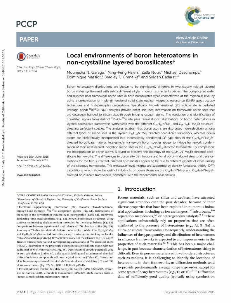
exhibit less extents of long-range order than crystalline structures.Such characteristics make diffraction-based analyses, which aresensitive to long-range framework order, less suitable for thistask. For example, powder X-ray diffraction (XRD) patterns ofas-synthesized C16H33N+Me3- and C16H33N+Me2Et-directed boro-silicates (with natural 29Si abundance) show small- (Fig. 1aand c) and high-angle reflections (Fig. 1b and d) in both boro-silicate materials, indicating a high degree of mesoscopiclamellar order and long-range framework order, respectively.The mesoscopic lamellar ordering was visually confirmed else-where by high resolution transmission electron microscopy forthe siliceous analog of the C16H33N+Me2Et-directed borosilicatematerial studied here,64 which also yields identical XRD and29Si NMR (see below) signatures.47 The XRD pattern of theC16H33N+Me3-borosilicate is also similar to the one obtained forthe siliceous analog.46 The basal distances of ca. 3.7 and 3.2 nmextracted from the low-angle reflections for the C16H33N+Me2Et-and C16H33N+Me3-borosilicate materials, respectively, indicatesimilarly high extents of vertical alignment (i.e., perpendicularto the layers) of the surfactant hydrophobic tails. In contrastto these reference silicate materials, however, bulk elementalanalyses summarized in Table 1 reveal the presence of boron inthe two materials whose XRD patterns are shown in Fig. 1. TheC16H33N+Me3- and C16H33N+Me2Et-directed borosilicate materialsare shown to have Si/B ratios of 142 and 52, respectively. Basedon the XRD and elemental analyses, B incorporation does notappear to induce substantial changes of long-range order inC16H33N+Me3- and C16H33N+Me2Et-directed layered borosilicates,as compared to their siliceous counterparts. However, it is notpossible to establish the locations of B atoms in the two boro-silicate frameworks by using XRD analyses alone. Consequently,distributions of B sites, as well as their interactions withstructure-directing surfactant species and silicon frameworksites have still remained elusive.
2.b. Short-range molecular structures from 29Si NMR data
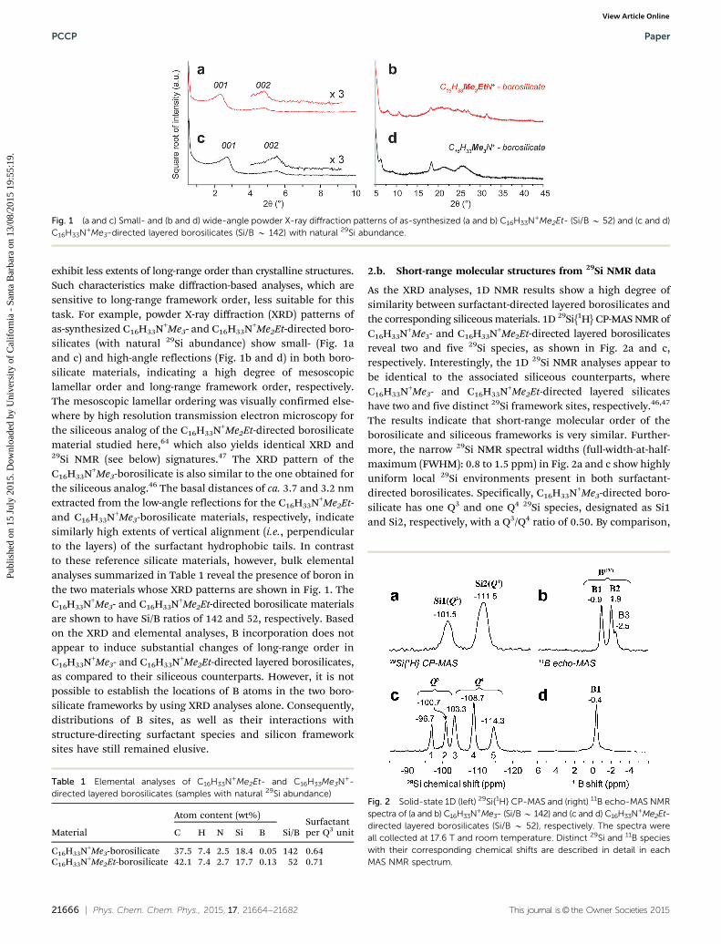
As the XRD analyses, 1D NMR results show a high degree ofsimilarity between surfactant-directed layered borosilicates andthe corresponding siliceous materials. 1D 29Si{1H} CP-MAS NMR ofC16H33N+Me3- and C16H33N+Me2Et-directed layered borosilicatesreveal two and five 29Si species, as shown in Fig. 2a and c,respectively. Interestingly, the 1D 29Si NMR analyses appear tobe identical to the associated siliceous counterparts, whereC16H33N+Me3- and C16H33N+Me2Et-directed layered silicateshave two and five distinct 29Si framework sites, respectively.46,47
The results indicate that short-range molecular order of theborosilicate and siliceous frameworks is very similar. Further-more, the narrow 29Si NMR spectral widths (full-width-at-half-maximum (FWHM): 0.8 to 1.5 ppm) in Fig. 2a and c show highlyuniform local 29Si environments present in both surfactant-directed borosilicates. Specifically, C16H33N+Me3-directed boro-silicate has one Q3 and one Q4 29Si species, designated as Si1and Si2, respectively, with a Q3/Q4 ratio of 0.50. By comparison,
Fig. 1 (a and c) Small- and (b and d) wide-angle powder X-ray diffraction patterns of as-synthesized (a and b) C16H33N+Me2Et- (Si/B B 52) and (c and d)C16H33N+Me3-directed layered borosilicates (Si/B B 142) with natural 29Si abundance.
Table 1 Elemental analyses of C16H33N+Me2Et- and C16H33Me3N+-directed layered borosilicates (samples with natural 29Si abundance)
Material
Atom content (wt%)
Si/BSurfactantper Q3 unitC H N Si B
C16H33N+Me3-borosilicate 37.5 7.4 2.5 18.4 0.05 142 0.64C16H33N+Me2Et-borosilicate 42.1 7.4 2.7 17.7 0.13 52 0.71
Fig. 2 Solid-state 1D (left) 29Si{1H} CP-MAS and (right) 11B echo-MAS NMRspectra of (a and b) C16H33N+Me3- (Si/B B 142) and (c and d) C16H33N+Me2Et-directed layered borosilicates (Si/B B 52), respectively. The spectra wereall collected at 17.6 T and room temperature. Distinct 29Si and 11B specieswith their corresponding chemical shifts are described in detail in eachMAS NMR spectrum.
PCCP Paper
Publ
ishe
d on
15
July
201
5. D
ownl
oade
d by
Uni
vers
ity o
f C
alif
orni
a -
Sant
a B
arba
ra o
n 13
/08/
2015
19:
55:1
9.
View Article Online

This journal is© the Owner Societies 2015 Phys. Chem. Chem. Phys., 2015, 17, 21664--21682 | 21667
two Q3 (Si1 and 2) and three Q4 29Si species (Si3, 4, and 5) arepresent in the C16H33N+Me2Et-directed borosilicate with anapproximate Q3/Q4 ratio of 0.67 (from quantitative 29Si NMRspectra not shown here). Two-dimensional experiments prob-ing the existence of 29Si–O–29Si linkages, which are shown inESI,† Fig. S1 and described in the corresponding captions, alsoindicate that the topologies (i.e. coordination sequences andring structures) are also identical in the borosilicate and thesiliceous analogs. Nevertheless, the 29Si NMR analyses do notprovide information that may be directly linked to the possiblepresence of B species in the frameworks of either of thesurfactant-directed borosilicate materials.
2.c. Probing the local structure around boron heteroatomsusing 11B NMR spectroscopy
In contrast to XRD and 29Si NMR analyses, 11B NMR spectroscopyprovides local information on 11B species in borosilicates. Forexample, 1D 11B echo-MAS reveals three and one four-coordinate11B sites in the C16H33N+Me3- and C16H33N+Me2Et-directedlayered borosilicates, as evidenced by various 11B NMR signals(FWHM: 0.3 to 0.5 ppm) shown in Fig. 2b and d, respectively.Both C16H33N+Me3- and C16H33N+Me2Et-directed silicate struc-tures are composed of four-coordinate framework Si sites only.B species (and by extension 11B nuclei) incorporated in theframework, upon substitution of any of these sites, would con-sequently become four-coordinated as well. In this regard, Bincorporation is expected to modify the host inorganic structures,primarily because of different sizes between Si and B atoms, butalso because of their different valence states, which will imply alocal charge-compensation mechanism around incorporated Batoms. To support such a hypothesis, the elemental analyses (i.e.,Si/B ratios) were used to estimate the possible fraction of 29SiNMR signals that result from 29Si sites near 11B species and aretherefore expected to differ from the signature of the corres-ponding reference silicate systems. The detailed description andresults are summarized in Table S1 (ESI†). Specifically, the resultsindicate that more than 15% of the 29Si NMR signals would beaffected if substantial influences of 11B sites on their neighboring29Si species exist in the C16H33N+Me2Et-directed borosilicate(assuming for instance a perturbation range of 5 Å or more).However, this estimation is in stark contrast to the 1D 29Si NMRspectrum (Fig. 2c), showing that the C16H33N+Me2Et-directedborosilicate has very similar 29Si environments to its siliceousanalog. Such facts suggest that framework B species exhibithighly localized influences on their nearby 29Si neighbors (verylikely less than 5 Å). The 11B NMR analyses demonstrate a singletype of well-defined 11B environment (0.3 ppm fwhm, Fig. 2d) and
suggest that B atoms seem to incorporate into one type of Si sitesin the C16H33N+Me2Et-directed borosilicate. This is possibly asimilar situation to the case of crystalline layered borosilicateRUB-19, of composition [Si9O18(OH)][Me2Pr2N+]�xH2O,33 forwhich the authors concluded that the small amount of B atomsincorporated were preferentially siting in a single T site based ona relatively sharp (ca. 1 ppm fwhm) dominant 11B NMR peak andXRD data. Interestingly the single 11B NMR line observed here forthe C16H33N+Me2Et-directed borosilicate is significantly sharper(0.3 ppm fwhm), further supporting the interpretation of a site-specific incorporation.
Very different from the case of C16H33N+Me2Et-directedborosilicate, 1D 11B NMR analyses provide solid evidence thatframework B species induce structural changes in the C16H33N+Me3-directed borosilicate frameworks. Specifically, three 11B signals at�0.9, �1.9, and �2.5 ppm are identified by 1D 11B NMR (Fig. 2b),all of which correspond to three distinct four-coordinate 11B sites,designated as B1, B2, and B3, respectively. This obviously exceedsthe number of distinct framework Si sites (two) available for Bincorporation, indicating that structural rearrangements occurin the C16H33N+Me3-directed borosilicate frameworks upon11B incorporation. While distinct 11B species are resolved andidentified by 1D 11B NMR, their exact locations and B-inducedstructural modifications in both surfactant-directed borosilicatematerials have still remained elusive.
Molecular interactions that involve 11B species and theirneighboring 1H species were measured to provide insightsabout B site distributions in both surfactant-directed borosilicatematerials. B atoms inserted into Q3 and Q4 29Si sites, designatedas Q3 and Q4 B species, respectively, are indeed expected to havedifferent extents of influences of 1H species. Q3 11B sites wouldtypically interact more strongly with 1H species than Q4 11B sites,due to the fact that Q3 11B sites bonded to negatively-chargednon-bridging O atoms would be charge balanced either by aproton coming from the reaction medium and forming hydroxyl-ated B–O–H species, or by positively-charged headgroups ofalkylammonium surfactants. Various spatial proximities between1H and 11B species could be distinguished by measuring trans-verse 11B dephasing times T2
0 (i.e., rate of signal loss during aspin echo) in the presence or absence of heteronuclear 11B–1Hdecoupling.69,70 The results are presented in ESI,† Fig. S2 andsummarized in Table 2 for both surfactant-directed borosilicatematerials. In the case of the C16H33N+Me3-directed borosilicate,11B sites B1 and B2 show identical T2
0 (i.e., 24 ms) in thepresence of heteronuclear 11B–1H decoupling. (Low 11B signalsensitivity and limited spectral resolution for 11B site B3 pre-vent reliable T2
0 measurements.) In contrast, 11B sites B1 and
Table 2 Transverse 11B dephasing times (T20) measured for C16H33N+Me2Et- (Si/B B 52) and C16H33N+Me3-directed layered borosilicates (Si/B B 142)
with and without heteronuclear 1H decoupling during 11B signal acquisition
Material 11B peak position (ppm)
T20 (ms)
11B assignmentDecoupling on Decoupling off
C16H33N+Me2Et-layered borosilicate �0.4 35 � 4 3.7 � 0.2 HydroxylatedC16H33N+Me3-layered borosilicate �0.9 24 � 1 6.7 � 0.4 Hydroxylated
�1.9 24 � 7 16 � 2 Fully condensed
Paper PCCP
Publ
ishe
d on
15
July
201
5. D
ownl
oade
d by
Uni
vers
ity o
f C
alif
orni
a -
Sant
a B
arba
ra o
n 13
/08/
2015
19:
55:1
9.
View Article Online
21668 | Phys. Chem. Chem. Phys., 2015, 17, 21664--21682 This journal is© the Owner Societies 2015
B2 exhibit significantly different T20 times, 7.0 and 16 ms, respec-
tively, in the absence of 1H decoupling, indicating that magic-angle-spinning alone is insufficient to remove all the heteronuclear11B dipole–1H dipole interactions. Residual 1H–11B couplingsconsequently affect T2
0 times of the 11B sites B1 and B2, revealinglarge differences that indicate that the 11B site B1 is under greaterinfluences from 1H species than 11B site B2. As such, the 11B siteB1 can be attributed to B atoms incorporated into Q3 29Si sites, andthe 11B site B2 refers to B atoms substituted into Q4 29Si sites. Thesimilar 11B shifts of the 11B sites B2 and B3 suggest that 11B site B3seems to stem from B atoms incorporated into the Q4 29Si site.Similarly, in the case of the C16H33N+Me2Et-directed borosilicate,the 11B signal shows very different T2
0 times that are 35 and 4.0 msmeasured in the presence and absence of 11B–1H decoupling,establishing that the associated four-coordinate 11B sites resultfrom the B atoms incorporated into Q3 29Si sites.
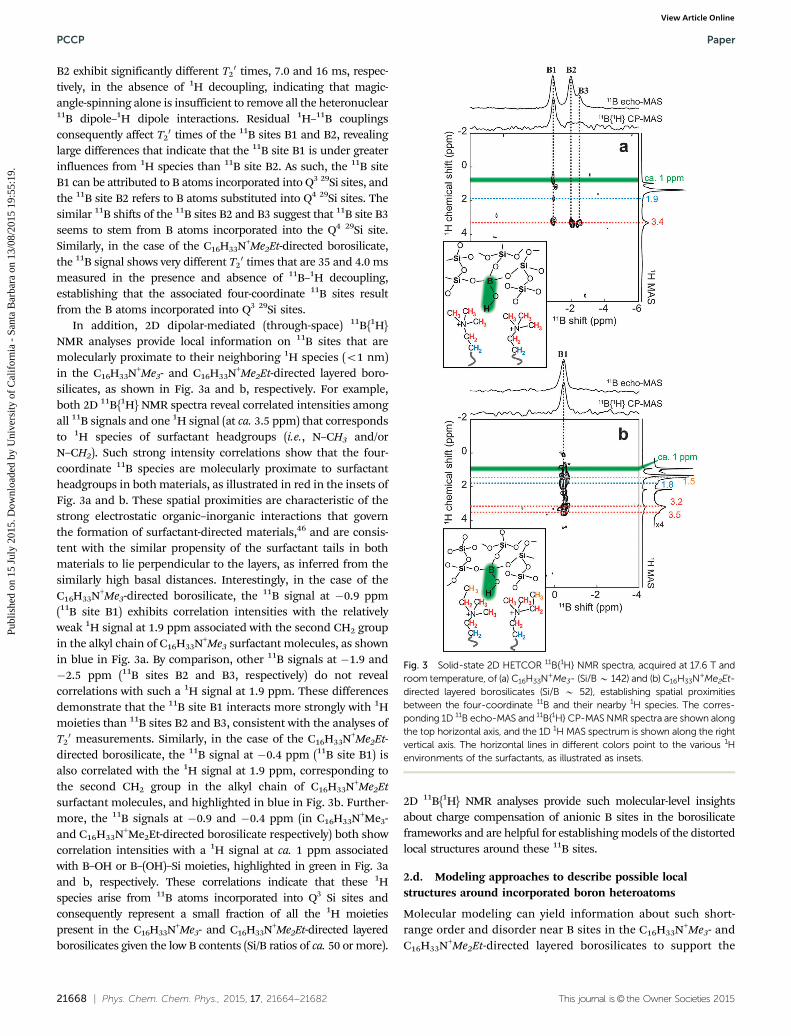
In addition, 2D dipolar-mediated (through-space) 11B{1H}NMR analyses provide local information on 11B sites that aremolecularly proximate to their neighboring 1H species (o1 nm)in the C16H33N+Me3- and C16H33N+Me2Et-directed layered boro-silicates, as shown in Fig. 3a and b, respectively. For example,both 2D 11B{1H} NMR spectra reveal correlated intensities amongall 11B signals and one 1H signal (at ca. 3.5 ppm) that correspondsto 1H species of surfactant headgroups (i.e., N–CH3 and/orN–CH2). Such strong intensity correlations show that the four-coordinate 11B species are molecularly proximate to surfactantheadgroups in both materials, as illustrated in red in the insets ofFig. 3a and b. These spatial proximities are characteristic of thestrong electrostatic organic–inorganic interactions that governthe formation of surfactant-directed materials,46 and are consis-tent with the similar propensity of the surfactant tails in bothmaterials to lie perpendicular to the layers, as inferred from thesimilarly high basal distances. Interestingly, in the case of theC16H33N+Me3-directed borosilicate, the 11B signal at �0.9 ppm(11B site B1) exhibits correlation intensities with the relativelyweak 1H signal at 1.9 ppm associated with the second CH2 groupin the alkyl chain of C16H33N+Me3 surfactant molecules, as shownin blue in Fig. 3a. By comparison, other 11B signals at �1.9 and�2.5 ppm (11B sites B2 and B3, respectively) do not revealcorrelations with such a 1H signal at 1.9 ppm. These differencesdemonstrate that the 11B site B1 interacts more strongly with 1Hmoieties than 11B sites B2 and B3, consistent with the analyses ofT20 measurements. Similarly, in the case of the C16H33N+Me2Et-
directed borosilicate, the 11B signal at �0.4 ppm (11B site B1) isalso correlated with the 1H signal at 1.9 ppm, corresponding tothe second CH2 group in the alkyl chain of C16H33N+Me2Etsurfactant molecules, and highlighted in blue in Fig. 3b. Further-more, the 11B signals at �0.9 and �0.4 ppm (in C16H33N+Me3-and C16H33N+Me2Et-directed borosilicate respectively) both showcorrelation intensities with a 1H signal at ca. 1 ppm associatedwith B–OH or B–(OH)–Si moieties, highlighted in green in Fig. 3aand b, respectively. These correlations indicate that these 1Hspecies arise from 11B atoms incorporated into Q3 Si sites andconsequently represent a small fraction of all the 1H moietiespresent in the C16H33N+Me3- and C16H33N+Me2Et-directed layeredborosilicates given the low B contents (Si/B ratios of ca. 50 or more).
2D 11B{1H} NMR analyses provide such molecular-level insightsabout charge compensation of anionic B sites in the borosilicateframeworks and are helpful for establishing models of the distortedlocal structures around these 11B sites.
2.d. Modeling approaches to describe possible localstructures around incorporated boron heteroatoms
Molecular modeling can yield information about such short-range order and disorder near B sites in the C16H33N+Me3- andC16H33N+Me2Et-directed layered borosilicates to support the
Fig. 3 Solid-state 2D HETCOR 11B{1H} NMR spectra, acquired at 17.6 T androom temperature, of (a) C16H33N+Me3- (Si/B B 142) and (b) C16H33N+Me2Et-directed layered borosilicates (Si/B B 52), establishing spatial proximitiesbetween the four-coordinate 11B and their nearby 1H species. The corres-ponding 1D 11B echo-MAS and 11B{1H} CP-MAS NMR spectra are shown alongthe top horizontal axis, and the 1D 1H MAS spectrum is shown along the rightvertical axis. The horizontal lines in different colors point to the various 1Henvironments of the surfactants, as illustrated as insets.
PCCP Paper
Publ
ishe
d on
15
July
201
5. D
ownl
oade
d by
Uni
vers
ity o
f C
alif
orni
a -
Sant
a B
arba
ra o
n 13
/08/
2015
19:
55:1
9.
View Article Online
This journal is© the Owner Societies 2015 Phys. Chem. Chem. Phys., 2015, 17, 21664--21682 | 21669
NMR analyses. In particular, calculation of NMR parametersusing density functional theory (DFT) is a powerful means tovalidate structural models. DFT calculations were conducted onrepresentative models of both surfactant-directed borosilicatesto examine and evaluate possible order and disorder nearframework B species in both surfactant-directed borosilicates,which can be described by (periodic) models that consist of asingle 2D borosilicate sheet, because the presence of flexibleand mobile surfactants in the inter-layer space of these layeredmaterials results in a high degree of stacking disorder. OurC16H33N+Me3-directed silicate models were based on the octo-silicate structure71 that possesses similar 29Si-NMR signaturesto the C16H33N+Me3-directed silicate.46,72 There are two distincttypes of Q4 and Q3 29Si sites (labeled as T1 and T2) in the octo-silicate corresponding to 29Si sites Si2 and Si1 in the C16H33N+Me3-directed layered silicate, respectively. On the other hand,advanced NMR-based structure determination protocols ledto the identification of three equally valid candidate frameworkmodels of the C16H33N+Me2Et-directed silicate,64 all of whichwere considered in our calculations. This silicate frameworkwas also found to be identical to the individual layers of twonewly reported materials HUS-2 of composition (per unit cell)[Si20O40(OH)4]4�[HO–(CH2)2–N+Me3]4�1.03(H2O)73 and CLS-1 ofcomposition [Si20O40(OH)4]4�[Me2N–C5H4N+–Et]4�7.6(H2O),65
which exhibit substantially higher extents of long-range inter-layer stacking order (albeit incomplete in CLS-165). Elementalanalyses (Table 1) indicate that the samples contain between0.6 and 0.7 surfactant molecules per Q3 groups. This meansthat, in analogy to the cases of octosilicate, HUS-2, and CLS-1materials,65,72,73 the rest of the negative charges of non-bridging O atoms is compensated in both borosilicates studiedhere by protons forming a strong Si–O–H� � �O–Si hydrogen-bonds between two adjacent Q3 Si sites, leading primarily to[Si5O10(OH)]� formula units for the framework. These protons,which are characterized by 1H NMR peaks in the 13–16 ppmrange in (at least partly) crystalline layered silicates octosilicate,HUS-2 and CLS-1, have never been clearly observed in the iso-structural surfactant-directed silicates. This is probably becausethey are considerably more mobile in the latter at roomtemperature and are potentially also exchanging with nearbySi5O11
2� units, which causes their 1H NMR resonance frequen-cies to be distributed across a large part of the 1H frequencyrange as a result of distributions of H-bond lengths, such thatthey are hidden at the feet of other 1H NMR peaks.
The basic idea of our modeling approach is to replace oneSi atom by a B atom in supercells made from the referenceC16H33N+Me3- and C16H33N+Me2Et-directed silicate systems tothen evaluate these borosilicate models and study the effect ofthe Si to B substitution on the framework structure. Thedifficulty here resides in the strategies used for the compensa-tion of the negative charges associated with the non-bridging Oatoms (those not compensated by a proton) and the incorpo-rated B atom. Two different approaches were tested to model thealkylammonium surfactant molecules. In the first, unsuccessful,approach described in the ESI† (Fig. S3, S4 and Tables S2, S3),surfactants with relatively short alkyl chains, such as
CH3–(CH2)3–N+Me3 or CH3–(CH2)3–N+Me2Et molecules, wereincluded in the inter-layer space of all candidate structuremodels to mimic charge-compensating surfactant molecules.While 11B NMR chemical shifts calculated with this methodseem to be reasonably reliable, calculated 29Si chemical shiftsare not consistent with the experimental NMR analyses. It hasbeen established before that freezing the surfactant-headgroupmotions by decreasing the temperature has a strong impacton 29Si NMR signals.74 The frozen states of the surfactant-mimicking molecules in our models are therefore not represen-tative of the mobile surfactants and their dynamically-averagedinfluence on the electronic structure of borosilicate layers atroom temperature.
In an alternative approach to model the complicatedorganic–inorganic interactions and their influence on the 29Siand 11B NMR signatures, the surfactant molecules were omittedand replaced by positive charges homogenously distributedacross the entire unit cell. This strong approximation was firstvalidated for the siliceous systems, as illustrated in Fig. S5(ESI†). Best results were obtained with calculations conductedon model unit cells that contain one H atom per pair of non-bridging O atoms, corresponding to reference compositions[Si8O16(OH)2]2� in the case of the C16H33N+Me3-directed silicate,[Si10O20(OH)2]2� for the C16H33N+Me2Et-directed silicate. Suchconfigurations would lead to borosilicates with 0.5 charge-compensating surfactant molecule per Q3 unit, which is reason-ably close to the elemental analyses of both surfactant-directedborosilicates (see Table 1). This modeling strategy appears tosubstantially improve the agreement between experimental andcalculated NMR parameters in the case of C16H33N+Me2Et-directedsilicates, as compared to the previously used approximation,64
where all non-bridging oxygen atoms were protonated to formsilanol groups. Importantly, these calculations further validatethe three ‘‘equally-valid framework structural models’’ thatwere previously established,64 two of which (structural models2 and 4 using the designation of ref. 64) appear to converge to asingle structure when only two of their non-bridging oxygenatoms are protonated. Structural models 2 and 3, obtained afteroptimization with 2H atoms per supercell, were considered asmodel systems to construct a second series of models of theC16H33N+Me2Et-directed borosilicates. In both series of systems,B atoms were then introduced by replacing one Si atom in a2 � 2 � 1 supercell, corresponding to models of compositions[BSi39O80(OH)8]9� for the C16H33N+Me2Et-directed borosilicates,and [BSi31O64(OH)8]9� for the C16H33N+Me3-directed borosilicates,as reported in Table 3, and in the first two rows of Table 4,respectively.
2.e. Evaluation of C16H33N+Me2Et-directed borosilicatemodels: calculated NMR data vs. advanced experimentalcorrelation NMR data
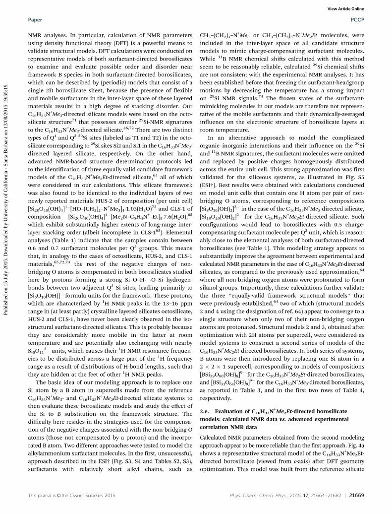
Calculated NMR parameters obtained from the second modelingapproach appear to be more reliable than the first approach. Fig. 4ashows a representative structural model of the C16H33N+Me2Et-directed borosilicate (viewed from c-axis) after DFT geometryoptimization. This model was built from the reference silicate
Paper PCCP
Publ
ishe
d on
15
July
201
5. D
ownl
oade
d by
Uni
vers
ity o
f C
alif
orni
a -
Sant
a B
arba
ra o
n 13
/08/
2015
19:
55:1
9.
View Article Online
21670 | Phys. Chem. Chem. Phys., 2015, 17, 21664--21682 This journal is© the Owner Societies 2015
framework structure 2 (Fig. S5, ESI†) in a 2 � 2 � 1 supercell,where one Si site Si1 was replaced by one B atom to form a B–OHunit. The resulting calculated 11B chemical shifts, including theones with B atoms incorporated into one of the five distinct Sisites in candidate framework structures 2 and 3, are summarizedin Table 3. Interestingly, these calculations match well-separatedranges of 11B chemical shifts for B atoms located in Q3 (�0.8 to0.9 ppm) or Q4 sites (�2.8 to �4.1 ppm). More importantly, therange of calculated 11B NMR signals for Q3 11B sites correspondswell to the experimental 11B signal at �0.4 ppm attributed toa BOH moiety formed by substitution of a Q3 29Si site in theC16H33N+Me2Et-borosilicates (Fig. 2d).
This modeling approach, where surfactants are omitted, alsoconsiderably improves the reliability of 29Si NMR calculations ascompared to the models with included surfactant-mimickingmolecules. The calculated 29Si chemical shifts for Qn 29Si sites(i.e. 29Si sites that are not connected to a B atom), shown in blackin Fig. 4c, are all in good agreement with the experimentalresults (Fig. 4b). The 29Si chemical shifts calculated for 29Si sitesneighboring the B atoms, Qn(1B) sites Si2, Si3, and S5, shown inyellow in Fig. 4c, also compare well to experimental data (Fig. 4d)that were obtained from advanced multi-dimensional solid-stateNMR techniques, and which will be discussed in further detailbelow. The structural rearrangements induced by B incorpora-tion may be probed through differences in the 29Si chemicalshifts between corresponding 29Si sites calculated in the boro-silicate and siliceous framework model, which are plotted inFig. 4e. The qualitative influences of an isolated B atom on itsnearby 29Si sites in terms of proximities are highlighted in greyin Fig. 4e. The shift difference is surprisingly weak for the
29Si sites with a next-nearest neighbor replaced by a B atom (theQ3(1B) species within the black ellipse in Fig. 4e), which may beexplained by a compensation between the effect due to thedifference in electronegativity between Si and B and the localgeometrical rearrangements caused by the smaller size of the Batom. T–O bond lengths, T–O–T bond angles and T–O–H–O–Thydrogen bond strengths all influence 29Si chemical shifts37 inways which appear here to oppose to the expected effect of thechange in electronegativity between Si and B (in analogy to thewell-known systematic effect of Si to Al substitutions). Thisstructural model with the B atom incorporated in one specificQ3 Si site appears to match with all the experimental datadiscussed so far. Similar calculations conducted for the othermodels, with B atoms incorporated into the 29Si site Si2 and/orusing candidate structure no. 3 as the reference silicate frame-work structure, will be discussed further below, in relation tothe identification of the crystallographic site on which the Batom is siting. For this, however, it is first necessary to explainhow the experimental 29Si spectrum of Fig. 4d featuring selec-tively Qn(1B) species was obtained.
The specific signature 29Si nuclei connected to 11B nucleithrough bridging O atoms exploits the unique ability of solid-state NMR spectroscopy to provide two-dimensional (2D) corre-lation experiments that are mediated through the 2J(11B–O–29Si)scalar couplings. Fig. 5a shows in red a 2D 2J(11B–O–29Si)-mediated heteronuclear multiple-quantum correlation (HMQC)11B{29Si} NMR spectrum of a C16H33N+Me2Et-directed layeredborosilicate material prepared with ca. 99% enrichment in 29Si.The 1D 11B echo-MAS and 29Si{1H} CP-MAS spectra of this29Si-enriched material are shown along the top horizontal and
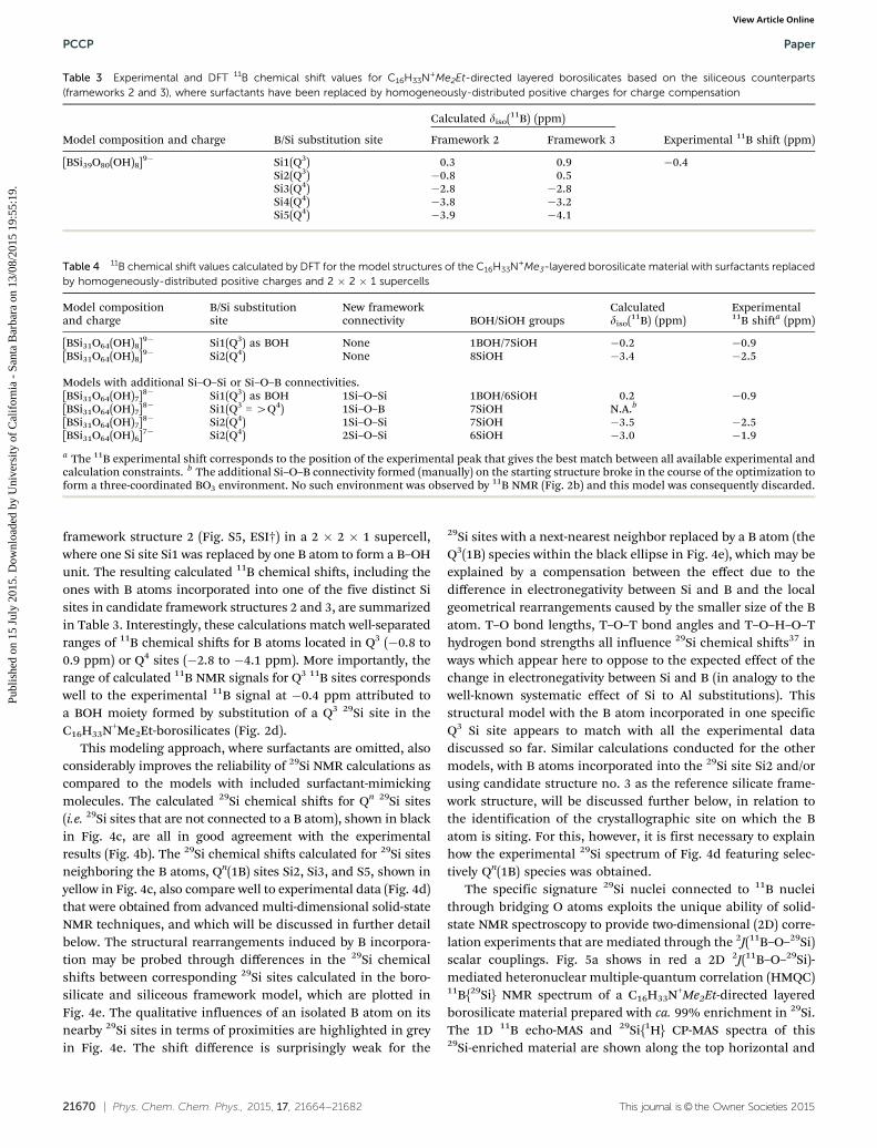
Table 3 Experimental and DFT 11B chemical shift values for C16H33N+Me2Et-directed layered borosilicates based on the siliceous counterparts(frameworks 2 and 3), where surfactants have been replaced by homogeneously-distributed positive charges for charge compensation
Model composition and charge B/Si substitution site
Calculated diso(11B) (ppm)
Experimental 11B shift (ppm)Framework 2 Framework 3
[BSi39O80(OH)8]9� Si1(Q3) 0.3 0.9 �0.4Si2(Q3) �0.8 0.5Si3(Q4) �2.8 �2.8Si4(Q4) �3.8 �3.2Si5(Q4) �3.9 �4.1
Table 4 11B chemical shift values calculated by DFT for the model structures of the C16H33N+Me3-layered borosilicate material with surfactants replacedby homogeneously-distributed positive charges and 2 � 2 � 1 supercells
Model compositionand charge
B/Si substitutionsite
New frameworkconnectivity BOH/SiOH groups
Calculateddiso(11B) (ppm)
Experimental11B shifta (ppm)
[BSi31O64(OH)8]9� Si1(Q3) as BOH None 1BOH/7SiOH �0.2 �0.9[BSi31O64(OH)8]9� Si2(Q4) None 8SiOH �3.4 �2.5
Models with additional Si–O–Si or Si–O–B connectivities.[BSi31O64(OH)7]8� Si1(Q3) as BOH 1Si–O–Si 1BOH/6SiOH 0.2 �0.9[BSi31O64(OH)7]8� Si1(Q3 = 4Q4) 1Si–O–B 7SiOH N.A.b
[BSi31O64(OH)7]8� Si2(Q4) 1Si–O–Si 7SiOH �3.5 �2.5[BSi31O64(OH)6]7� Si2(Q4) 2Si–O–Si 6SiOH �3.0 �1.9
a The 11B experimental shift corresponds to the position of the experimental peak that gives the best match between all available experimental andcalculation constraints. b The additional Si–O–B connectivity formed (manually) on the starting structure broke in the course of the optimization toform a three-coordinated BO3 environment. No such environment was observed by 11B NMR (Fig. 2b) and this model was consequently discarded.
PCCP Paper
Publ
ishe
d on
15
July
201
5. D
ownl
oade
d by
Uni
vers
ity o
f C
alif
orni
a -
Sant
a B
arba
ra o
n 13
/08/
2015
19:
55:1
9.
View Article Online

This journal is© the Owner Societies 2015 Phys. Chem. Chem. Phys., 2015, 17, 21664--21682 | 21671
the right vertical axis of the 2D 11B{29Si} spectrum. Both aresimilar to the 1D spectra of the corresponding C16H33N+Me2Et-directed layered borosilicate with natural abundance of 29Si
(Fig. 2c and d), except for the presence of a boron-containingimpurity (marked with a star in the 1D 11B echo-MAS spectrum).Various correlated intensities in this 2D 11B{29Si} NMR spectrum(Fig. 5a, in red) reveal different 29Si sites covalently bonded to 11Batoms via bridging oxygen atoms in the borosilicate framework.It is the 29Si projection of this 2D spectrum, shown in red on theright of Fig. 5a, that was included in Fig. 4d for direct comparisonwith calculated 29Si chemical shifts corresponding to Qn(1B) 29Sienvironments. Because they lack a 11B–O–29Si connection, 29Si Qn
sites are indeed totally filtered out in the 2D correlation spectrum,and thus in its 29Si projection. Details of the 2D spectrum revealthree distinct 29Si signals at �98.4, �100.5 and �113.8 ppm thatare correlated with one 11B signal at �0.4 ppm. As mentionedabove, the small broadening of this 11B signal suggests a highlyuniform single type of 11B environment. Consequently, the threetypes of 29Si–O–11B correlations indicate that every incorporated Batom is connected to three distinct Si atoms (Q3(1B) or Q4(1B)) viabridging oxygen atoms. Specifically, two of the three Qn(1B) 29Sisites revealed in the J-mediated 11B{29Si} correlation NMRspectrum fall within a region of the 29Si spectrum that is com-patible with Q3(1B) signatures, consistent with the connecti-vities established from the siliceous counterpart, where each Q3
29Si site is connected to another Q3 29Si site. Such informationallows us to confirm that the 11B signal at �0.4 ppm can beattributed to B atoms incorporated into one of the two types ofQ3 Si sites. Additionally, the local topology near B sites in theC16H33N+Me2Et-directed borosilicate does not appear to rearrangeduring framework crystallization. As will be discussed furtherbelow this is in stark contrast to the case of the C16H33N+Me3-directed borosilicate material.
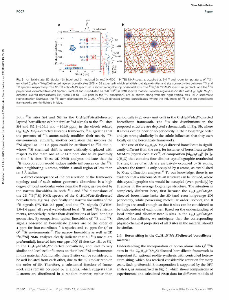
While the 2D J-mediated (through-bond) 11B{29Si} NMRanalyses provide specific information on the 11B sites that arecovalently bonded to the next-nearest-neighbor 29Si sites, 29Sisites in the first coordination shells may be spatially close to 11Bsites in the C16H33N+Me2Et-directed layered borosilicate frame-work, which can be revealed via 2D dipolar-mediated 11B{29Si}NMR experiments. Fig. 5a shows in blue a 2D dipolar-mediatedHMQC 11B{29Si} NMR spectrum of the ca. 99% 29Si-enrichedC16H33N+Me2Et-directed layered borosilicate. Intensity correla-tions that involve the impurity, identified by the 11B signal atca. 4 ppm in the 1D 11B NMR spectrum, are resolved using this2D dipolar-mediated 11B{29Si} NMR technique, but they aredistinguishable from the NMR signature of the layered boro-silicate. The 11B signal at ca. �0.4 ppm exhibits intensity correla-tions with the 29Si signals at �98.4, �100.5 and �113.8 ppm inthe 2D dipolar-mediated 11B{29Si} NMR spectrum (in blue, Fig. 5a),consistent with the 2D J-mediated 11B{29Si} NMR spectrum (in red,Fig. 5a), because of the short distances (ca. 3 Å) between the29Si–O–11B site pairs. More importantly, additional correlatedintensities are shown between the 11B signal at �0.4 ppm andthe 29Si signals at�111.3 and�108.6 ppm, as well as a shoulderat ca. �101.0 ppm, all of which correspond to 29Si sites that aremolecularly proximate to (ca. 5 Å or less) yet not connected withthe 11B sites. Interestingly, the 29Si signals at �108.6 and�101.0 ppm are very close to the 29Si signals at �108.7 and�100.7 ppm, associated with 29Si sites Si4 and Si2, respectively.
Fig. 4 (a) DFT-optimized structural model of C4H9N+Me2Et-directed layeredborosilicates with one 11B atom inserted into one 29Si site 1 (Q3 29Si), whichwas constructed using a 2 � 2 � 1 supercell and has 8 1H atoms as well ashomogenously distributed positive charges for charge compensation. (b) The1D 29Si NMR MAS spectrum of C16H33Me2EtN+-directed layered borosilicates(Si/B B 52) is compared with (c) the calculated 29Si NMR spectrum (in red) viaDFT calculation that includes 29Si signals corresponding to distinct types ofQn (in black) and Qn(1B) 29Si species (in orange). (d) The 1D 29Si projectionextracted from the 2D J-mediated HMQC 11B{29Si} NMR spectrum shows29Si signals associated with Qn(1B) 29Si sites. (e) A summary plot manifestsdifferences of calculated 29Si chemical shifts between the borosilicate modeland the silicate model (i.e., no 11B incorporation) as a function of relativedistances of various 29Si sites with respect to the nearest B atoms. Theinfluences of B atoms on borosilicate frameworks are depicted in grey forvisual illustrations.
Paper PCCP
Publ
ishe
d on
15
July
201
5. D
ownl
oade
d by
Uni
vers
ity o
f C
alif
orni
a -
Sant
a B
arba
ra o
n 13
/08/
2015
19:
55:1
9.
View Article Online
21672 | Phys. Chem. Chem. Phys., 2015, 17, 21664--21682 This journal is© the Owner Societies 2015
Both 29Si sites Si4 and Si2 in the C16H33N+Me2Et-directedlayered borosilicate exhibit similar 29Si signals to the 29Si sitesSi4 and Si2 (�109.1 and �101.0 ppm) in the closely relatedC16H33N+Me2Et-directed siliceous framework,46 suggesting thatthe presence of 11B atoms subtly modifies their nearby 29Sienvironments. Similarly, another correlation that involves the29Si signal at �111.3 ppm could be attributed to 29Si site 5,whose 29Si chemical shift is more distinctly displaced withrespect to the main one at �114.7 ppm due to its proximityto the 11B sites. These 2D NMR analyses indicate that the11B incorporation would induce subtle influences on the 29Sisites neighboring B atoms, within a small region of less thanca. 5 Å radius.
A direct consequence of the preservation of the frameworktopology and of such minor geometric distortions is a highdegree of local molecular order near the B sites, as revealed bythe narrow linewidths in both 11B and 29Si dimensions ofthe 2D 11B{29Si} NMR spectra of the C16H33N+Me2Et-directedborosilicates (Fig. 5a). Specifically, the narrow linewidths of the11B signals (FWHM: 0.3 ppm) and the 29Si signals (FWHM:1.0–1.6 ppm) all reveal well-defined local 11B and 29Si environ-ments, respectively, rather than distributions of local bondinggeometries. By comparison, typical linewidths of 11B and 29Sisignals observed in borosilicate glasses are of the order of4 ppm for four-coordinate 11B species and 10 ppm for Q3 orQ4 29Si environments.75 The narrow linewidths as well as 2D11B{29Si} NMR analyses clearly indicate that all 11B nuclei arepreferentially inserted into one type of Q3 Si sites (i.e., Si1 or Si2)in the C16H33N+Me2Et-directed borosilicate, and lead to verysimilar and localized influences on their local 29Si environmentsin this material. Additionally, these B sites can be considered tobe well isolated from each other, due to the Si/B molar ratio onthe order of 50. Therefore, a substantial fraction of frame-work sites remain occupied by Si atoms, which suggests thatB atoms are distributed in a random manner, rather than
periodically (e.g., every unit cell) in the C16H33N+Me2Et-directedborosilicate framework. The 11B site distributions in theproposed structure are depicted schematically in Fig. 5b, whereB atoms exhibit poor or no periodicity in their long-range orderand yet strong similarity in the subtle influences that they exertlocally on the borosilicate frameworks.
The case of the C16H33N+Me2Et-directed borosilicate is signifi-cantly different from the case, for instance, of borosilicate zeoliteMCM-70 (crystal code MVY76) of composition [Si10B2O24]2�[K+]2�2(H2O) that contains four distinct crystallographic tetrahedralSi sites, three of which are exclusively occupied by Si atoms,whereas the fourth is only occupied by B atoms, as establishedby X-ray diffraction analyses.32 To our knowledge, there is noevidence that a siliceous MCM-70 structure can be formed, wherethis crystallographic site would be occupied (even partially) bySi atoms in the average long-range structure. The situation iscompletely different here, first because the C16H33N+Me2Et-directed borosilicate lacks the 3D (and even long-range 2D)periodicity, while possessing molecular order. Second, the Bloadings are small enough so that B sites can be considered tobe independent of each other. Based on the understanding oflocal order and disorder near B sites in the C16H33N+Me2Et-directed borosilicate, we anticipate that the correspondingphysico-chemical properties of all B sites in the material shouldbe similar.
2.f. Boron siting in the C16H33N+Me2Et-directed borosilicatematerial
Understanding the incorporation of boron atoms into Q3 29Sisites in the C16H33N+Me2Et-directed borosilicate framework isimportant for rational zeolite synthesis with controlled hetero-atom siting, which has received considerable attention for manyyears. Such preferential B incorporation is supported by the DFTanalyses, as summarized in Fig. 6, which shows comparisons ofexperimental and calculated NMR data for different models of
Fig. 5 (a) Solid-state 2D dipolar- (in blue) and J-mediated (in red) HMQC 11B{29Si} NMR spectra, acquired at 9.4 T and room temperature, of 29Si-enriched C16H33N+Me2Et-directed layered borosilicates (Si/B B 52 expected), which establish spatial proximities and site connectivities between 29Si and11B species, respectively. The 1D 11B echo-MAS spectrum is shown along the top horizontal axis. The 29Si{1H} CP-MAS spectrum (in black) and the 29Siprojections, extracted from 2D dipolar- (in blue) and J-mediated (in red) 11B{29Si} NMR spectra that focus on the regions associated with C16H33N+Me2Et-directed layered borosilicates (i.e., from 1.0 to �2.0 ppm in the 11B dimension), are all shown along with the right vertical axis. (b) A schematicrepresentation illustrates the 11B atom distributions in C16H33N+Me2Et-directed layered borosilicates, where the influences of 11B sites on borosilicateframeworks are highlighted in blue.
PCCP Paper
Publ
ishe
d on
15
July
201
5. D
ownl
oade
d by
Uni
vers
ity o
f C
alif
orni
a -
Sant
a B
arba
ra o
n 13
/08/
2015
19:
55:1
9.
View Article Online
This journal is© the Owner Societies 2015 Phys. Chem. Chem. Phys., 2015, 17, 21664--21682 | 21673
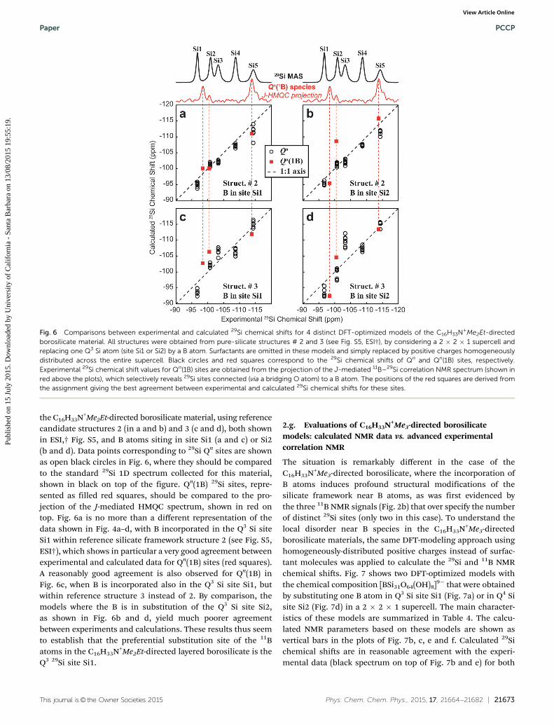
the C16H33N+Me2Et-directed borosilicate material, using referencecandidate structures 2 (in a and b) and 3 (c and d), both shownin ESI,† Fig. S5, and B atoms siting in site Si1 (a and c) or Si2(b and d). Data points corresponding to 29Si Qn sites are shownas open black circles in Fig. 6, where they should be comparedto the standard 29Si 1D spectrum collected for this material,shown in black on top of the figure. Qn(1B) 29Si sites, repre-sented as filled red squares, should be compared to the pro-jection of the J-mediated HMQC spectrum, shown in red ontop. Fig. 6a is no more than a different representation of thedata shown in Fig. 4a–d, with B incorporated in the Q3 Si siteSi1 within reference silicate framework structure 2 (see Fig. S5,ESI†), which shows in particular a very good agreement betweenexperimental and calculated data for Qn(1B) sites (red squares).A reasonably good agreement is also observed for Qn(1B) inFig. 6c, when B is incorporated also in the Q3 Si site Si1, butwithin reference structure 3 instead of 2. By comparison, themodels where the B is in substitution of the Q3 Si site Si2,as shown in Fig. 6b and d, yield much poorer agreementbetween experiments and calculations. These results thus seemto establish that the preferential substitution site of the 11Batoms in the C16H33N+Me2Et-directed layered borosilicate is theQ3 29Si site Si1.
2.g. Evaluations of C16H33N+Me3-directed borosilicatemodels: calculated NMR data vs. advanced experimentalcorrelation NMR
The situation is remarkably different in the case of theC16H33N+Me3-directed borosilicate, where the incorporation ofB atoms induces profound structural modifications of thesilicate framework near B atoms, as was first evidenced bythe three 11B NMR signals (Fig. 2b) that over specify the numberof distinct 29Si sites (only two in this case). To understand thelocal disorder near B species in the C16H33N+Me3-directedborosilicate materials, the same DFT-modeling approach usinghomogeneously-distributed positive charges instead of surfac-tant molecules was applied to calculate the 29Si and 11B NMRchemical shifts. Fig. 7 shows two DFT-optimized models withthe chemical composition [BSi31O64(OH)8]9� that were obtainedby substituting one B atom in Q3 Si site Si1 (Fig. 7a) or in Q4 Sisite Si2 (Fig. 7d) in a 2 � 2 � 1 supercell. The main character-istics of these models are summarized in Table 4. The calcu-lated NMR parameters based on these models are shown asvertical bars in the plots of Fig. 7b, c, e and f. Calculated 29Sichemical shifts are in reasonable agreement with the experi-mental data (black spectrum on top of Fig. 7b and e) for both
Fig. 6 Comparisons between experimental and calculated 29Si chemical shifts for 4 distinct DFT-optimized models of the C16H33N+Me2Et-directedborosilicate material. All structures were obtained from pure-silicate structures # 2 and 3 (see Fig. S5, ESI†), by considering a 2 � 2 � 1 supercell andreplacing one Q3 Si atom (site Si1 or Si2) by a B atom. Surfactants are omitted in these models and simply replaced by positive charges homogeneouslydistributed across the entire supercell. Black circles and red squares correspond to the 29Si chemical shifts of Qn and Qn(1B) sites, respectively.Experimental 29Si chemical shift values for Qn(1B) sites are obtained from the projection of the J-mediated 11B–29Si correlation NMR spectrum (shown inred above the plots), which selectively reveals 29Si sites connected (via a bridging O atom) to a B atom. The positions of the red squares are derived fromthe assignment giving the best agreement between experimental and calculated 29Si chemical shifts for these sites.
Paper PCCP
Publ
ishe
d on
15
July
201
5. D
ownl
oade
d by
Uni
vers
ity o
f C
alif
orni
a -
Sant
a B
arba
ra o
n 13
/08/
2015
19:
55:1
9.
View Article Online
21674 | Phys. Chem. Chem. Phys., 2015, 17, 21664--21682 This journal is© the Owner Societies 2015
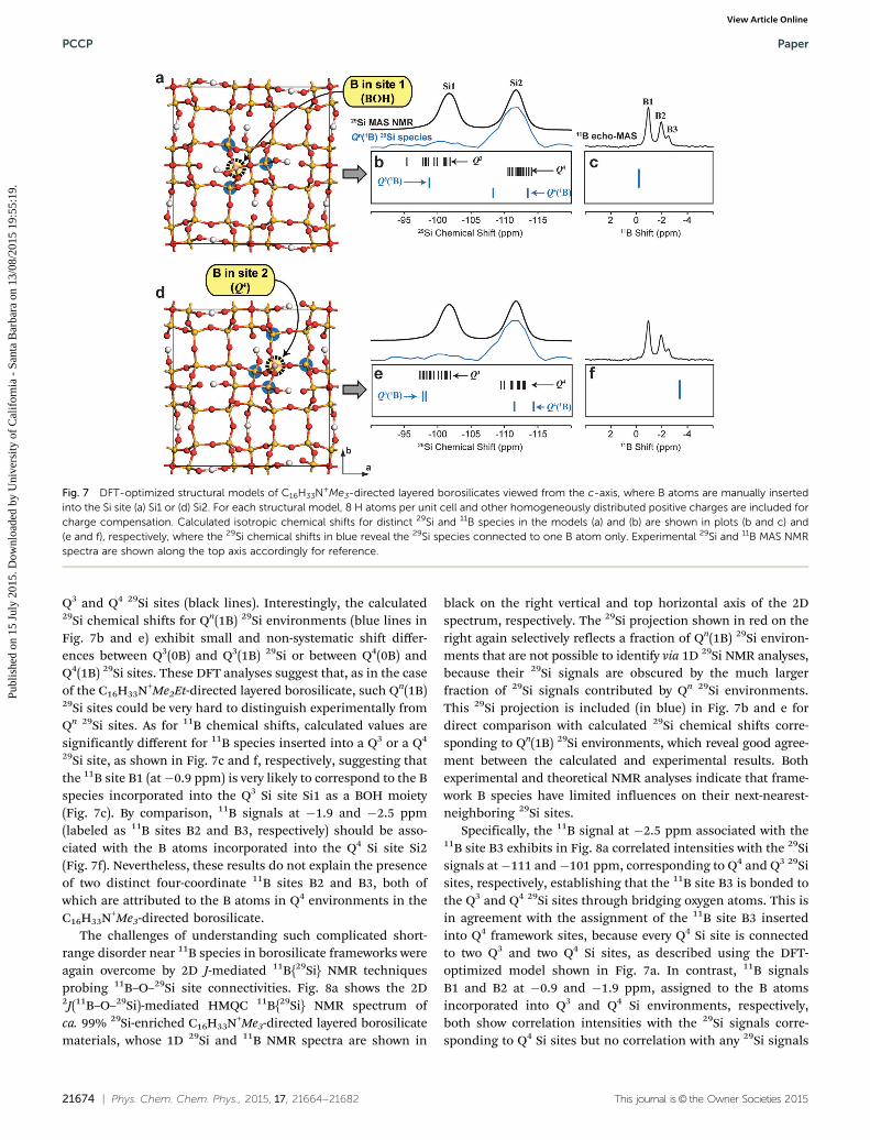
Q3 and Q4 29Si sites (black lines). Interestingly, the calculated29Si chemical shifts for Qn(1B) 29Si environments (blue lines inFig. 7b and e) exhibit small and non-systematic shift differ-ences between Q3(0B) and Q3(1B) 29Si or between Q4(0B) andQ4(1B) 29Si sites. These DFT analyses suggest that, as in the caseof the C16H33N+Me2Et-directed layered borosilicate, such Qn(1B)29Si sites could be very hard to distinguish experimentally fromQn 29Si sites. As for 11B chemical shifts, calculated values aresignificantly different for 11B species inserted into a Q3 or a Q4
29Si site, as shown in Fig. 7c and f, respectively, suggesting thatthe 11B site B1 (at�0.9 ppm) is very likely to correspond to the Bspecies incorporated into the Q3 Si site Si1 as a BOH moiety(Fig. 7c). By comparison, 11B signals at �1.9 and �2.5 ppm(labeled as 11B sites B2 and B3, respectively) should be asso-ciated with the B atoms incorporated into the Q4 Si site Si2(Fig. 7f). Nevertheless, these results do not explain the presenceof two distinct four-coordinate 11B sites B2 and B3, both ofwhich are attributed to the B atoms in Q4 environments in theC16H33N+Me3-directed borosilicate.
The challenges of understanding such complicated short-range disorder near 11B species in borosilicate frameworks wereagain overcome by 2D J-mediated 11B{29Si} NMR techniquesprobing 11B–O–29Si site connectivities. Fig. 8a shows the 2D2J(11B–O–29Si)-mediated HMQC 11B{29Si} NMR spectrum ofca. 99% 29Si-enriched C16H33N+Me3-directed layered borosilicatematerials, whose 1D 29Si and 11B NMR spectra are shown in
black on the right vertical and top horizontal axis of the 2Dspectrum, respectively. The 29Si projection shown in red on theright again selectively reflects a fraction of Qn(1B) 29Si environ-ments that are not possible to identify via 1D 29Si NMR analyses,because their 29Si signals are obscured by the much largerfraction of 29Si signals contributed by Qn 29Si environments.This 29Si projection is included (in blue) in Fig. 7b and e fordirect comparison with calculated 29Si chemical shifts corre-sponding to Qn(1B) 29Si environments, which reveal good agree-ment between the calculated and experimental results. Bothexperimental and theoretical NMR analyses indicate that frame-work B species have limited influences on their next-nearest-neighboring 29Si sites.
Specifically, the 11B signal at �2.5 ppm associated with the11B site B3 exhibits in Fig. 8a correlated intensities with the 29Sisignals at�111 and�101 ppm, corresponding to Q4 and Q3 29Sisites, respectively, establishing that the 11B site B3 is bonded tothe Q3 and Q4 29Si sites through bridging oxygen atoms. This isin agreement with the assignment of the 11B site B3 insertedinto Q4 framework sites, because every Q4 Si site is connectedto two Q3 and two Q4 Si sites, as described using the DFT-optimized model shown in Fig. 7a. In contrast, 11B signalsB1 and B2 at �0.9 and �1.9 ppm, assigned to the B atomsincorporated into Q3 and Q4 Si environments, respectively,both show correlation intensities with the 29Si signals corre-sponding to Q4 Si sites but no correlation with any 29Si signals
Fig. 7 DFT-optimized structural models of C16H33N+Me3-directed layered borosilicates viewed from the c-axis, where B atoms are manually insertedinto the Si site (a) Si1 or (d) Si2. For each structural model, 8 H atoms per unit cell and other homogeneously distributed positive charges are included forcharge compensation. Calculated isotropic chemical shifts for distinct 29Si and 11B species in the models (a) and (b) are shown in plots (b and c) and(e and f), respectively, where the 29Si chemical shifts in blue reveal the 29Si species connected to one B atom only. Experimental 29Si and 11B MAS NMRspectra are shown along the top axis accordingly for reference.
PCCP Paper
Publ
ishe
d on
15
July
201
5. D
ownl
oade
d by
Uni
vers
ity o
f C
alif
orni
a -
Sant
a B
arba
ra o
n 13
/08/
2015
19:
55:1
9.
View Article Online
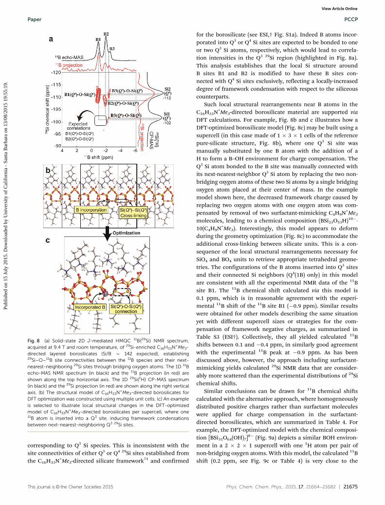
This journal is© the Owner Societies 2015 Phys. Chem. Chem. Phys., 2015, 17, 21664--21682 | 21675
corresponding to Q3 Si species. This is inconsistent with thesite connectivities of either Q3 or Q4 29Si sites established fromthe C16H33N+Me3-directed silicate framework71 and confirmed
for the borosilicate (see ESI,† Fig. S1a). Indeed B atoms incor-porated into Q3 or Q4 Si sites are expected to be bonded to oneor two Q3 Si atoms, respectively, which would lead to correla-tion intensities in the Q3 29Si region (highlighted in Fig. 8a).This analysis establishes that the local Si structure aroundB sites B1 and B2 is modified to have these B sites con-nected with Q4 Si sites exclusively, reflecting a locally-increaseddegree of framework condensation with respect to the siliceouscounterparts.
Such local structural rearrangements near B atoms in theC16H33N+Me3-directed borosilicate material are supported viaDFT calculations. For example, Fig. 8b and c illustrates how aDFT-optimized borosilicate model (Fig. 8c) may be built using asupercell (in this case made of 1 � 3 � 1 cells of the referencepure-silicate structure, Fig. 8b), where one Q3 Si site wasmanually substituted by one B atom with the addition of aH to form a B–OH environment for charge compensation. TheQ3 Si atom bonded to the B site was manually connected withits next-nearest-neighbor Q3 Si atom by replacing the two non-bridging oxygen atoms of these two Si atoms by a single bridgingoxygen atom placed at their center of mass. In the examplemodel shown here, the decreased framework charge caused byreplacing two oxygen atoms with one oxygen atom was com-pensated by removal of two surfactant-mimicking C4H9N+Me3
molecules, leading to a chemical composition (BSi23O53H)10��10(C4H9N+Me3). Interestingly, this model appears to deformduring the geometry optimization (Fig. 8c) to accommodate theadditional cross-linking between silicate units. This is a con-sequence of the local structural rearrangements necessary forSiO4 and BO4 units to retrieve appropriate tetrahedral geome-tries. The configurations of the B atoms inserted into Q3 sitesand their connected Si neighbors (Q4(1B) only) in this modelare consistent with all the experimental NMR data of the 11Bsite B1. The 11B chemical shift calculated via this model is0.1 ppm, which is in reasonable agreement with the experi-mental 11B shift of the 11B site B1 (�0.9 ppm). Similar resultswere obtained for other models describing the same situationyet with different supercell sizes or strategies for the com-pensation of framework negative charges, as summarized inTable S3 (ESI†). Collectively, they all yielded calculated 11Bshifts between 0.1 and �0.4 ppm, in similarly good agreementwith the experimental 11B peak at �0.9 ppm. As has beendiscussed above, however, the approach including surfactant-mimicking yields calculated 29Si NMR data that are consider-ably more scattered than the experimental distributions of 29Sichemical shifts.
Similar conclusions can be drawn for 11B chemical shiftscalculated with the alternative approach, where homogeneouslydistributed positive charges rather than surfactant moleculeswere applied for charge compensation in the surfactant-directed borosilicates, which are summarized in Table 4. Forexample, the DFT-optimized model with the chemical composi-tion [BSi31O64(OH)7]8� (Fig. 9a) depicts a similar BOH environ-ment in a 2 � 2 � 1 supercell with one 1H atom per pair ofnon-bridging oxygen atoms. With this model, the calculated 11Bshift (0.2 ppm, see Fig. 9c or Table 4) is very close to the
Fig. 8 (a) Solid-state 2D J-mediated HMQC 11B{29Si} NMR spectrum,acquired at 9.4 T and room temperature, of 29Si-enriched C16H33N+Me3-directed layered borosilicates (Si/B B 142 expected), establishing29Si–O–11B site connectivities between the 11B species and their next-nearest-neighboring 29Si sites through bridging oxygen atoms. The 1D 11Becho-MAS NMR spectrum (in black) and the 11B projection (in red) areshown along the top horizontal axis. The 1D 29Si{1H} CP-MAS spectrum(in black) and the 29Si projection (in red) are shown along the right verticalaxis. (b) The structural model of C16H33N+Me3-directed borosilicates forDFT optimization was constructed using multiple unit cells. (c) An exampleis selected to illustrate local structural changes in the DFT-optimizedmodel of C16H33N+Me3-directed borosilicates per supercell, where one11B atom is inserted into a Q3 site, inducing framework condensationsbetween next-nearest-neighboring Q3 29Si sites.
Paper PCCP
Publ
ishe
d on
15
July
201
5. D
ownl
oade
d by
Uni
vers
ity o
f C
alif
orni
a -
Sant
a B
arba
ra o
n 13
/08/
2015
19:
55:1
9.
View Article Online
21676 | Phys. Chem. Chem. Phys., 2015, 17, 21664--21682 This journal is© the Owner Societies 2015
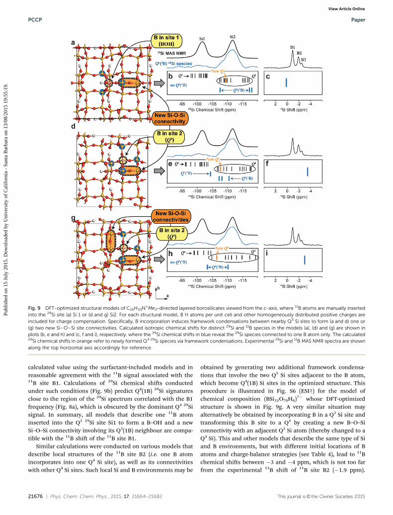
calculated value using the surfactant-included models and inreasonable agreement with the 11B signal associated with the11B site B1. Calculations of 29Si chemical shifts conductedunder such conditions (Fig. 9b) predict Q4(1B) 29Si signaturesclose to the region of the 29Si spectrum correlated with the B1frequency (Fig. 8a), which is obscured by the dominant Q4 29Sisignal. In summary, all models that describe one 11B atominserted into the Q3 29Si site Si1 to form a B–OH and a newSi–O–Si connectivity involving its Q3(1B) neighbour are compa-tible with the 11B shift of the 11B site B1.
Similar calculations were conducted on various models thatdescribe local structures of the 11B site B2 (i.e. one B atomincorporates into one Q4 Si site), as well as its connectivitieswith other Q4 Si sites. Such local Si and B environments may be
obtained by generating two additional framework condensa-tions that involve the two Q3 Si sites adjacent to the B atom,which become Q4(1B) Si sites in the optimized structure. Thisprocedure is illustrated in Fig. S6 (ESI†) for the model ofchemical composition (BSi31O70H6)7� whose DFT-optimizedstructure is shown in Fig. 9g. A very similar situation mayalternatively be obtained by incorporating B in a Q3 Si site andtransforming this B site to a Q4 by creating a new B–O–Siconnectivity with an adjacent Q3 Si atom (thereby changed to aQ4 Si). This and other models that describe the same type of Siand B environments, but with different initial locations of Batoms and charge-balance strategies (see Table 4), lead to 11Bchemical shifts between �3 and �4 ppm, which is not too farfrom the experimental 11B shift of 11B site B2 (�1.9 ppm).
Fig. 9 DFT-optimized structural models of C16H33N+Me3-directed layered borosilicates viewed from the c-axis, where 11B atoms are manually insertedinto the 29Si site (a) Si 1 or (d and g) Si2. For each structural model, 8 H atoms per unit cell and other homogeneously distributed positive charges areincluded for charge compensation. Specifically, B incorporation induces framework condensations between nearby Q3 Si sites to form (a and d) one or(g) two new Si–O–Si site connectivities. Calculated isotropic chemical shifts for distinct 29Si and 11B species in the models (a), (d) and (g) are shown inplots (b, e and h) and (c, f and i), respectively, where the 29Si chemical shifts in blue reveal the 29Si species connected to one B atom only. The calculated29Si chemical shifts in orange refer to newly formed Q4 29Si species via framework condensations. Experimental 29Si and 11B MAS NMR spectra are shownalong the top horizontal axis accordingly for reference.
PCCP Paper
Publ
ishe
d on
15
July
201
5. D
ownl
oade
d by
Uni
vers
ity o
f C
alif
orni
a -
Sant
a B
arba
ra o
n 13
/08/
2015
19:
55:1
9.
View Article Online
This journal is© the Owner Societies 2015 Phys. Chem. Chem. Phys., 2015, 17, 21664--21682 | 21677
In combination with 2D NMR data, these calculations thus shedlight on the possible rearrangements of the framework topology(i.e., the coordination sequences and ring structures) that maytake place upon B incorporation into the C16H33N+Me3-directedlayered borosilicate material during framework ordering. Such Bincorporation appears to promote or to be facilitated by thecondensation of originally incompletely-condensed Si atomsaround the incorporated B site.
2.h. Understanding the differences between C16H33N+Me2Et-and C16H33N+Me3-directed borosilicate materials
When B atoms are incorporated into the two surfactant-directedsilicate frameworks with very similar lamellar morphologies (seeSection 2.a), prepared under identical synthesis conditions withvery similar structure-directing alkylammonium molecules, pro-found differences appear between them. XRD and 11B{1H} corre-lation NMR data (Section 2.c), along with 29Si{1H} correlationNMR data published previously for the siliceous analogs,46
suggest that the orientations of the surfactant molecules andtheir interactions with silicate layers are similar in both materi-als. (In fact the latter appear to primarily depend on the nature(Q3 or Q4) of the site in which the boron is incorporated.) Weconsequently believe that the origin(s) of the different boronsiting and distributions between these materials must be soughtinstead in the molecular structures of their layered frameworks.The presence of B atoms of smaller size as compared with Siatoms in a silicate framework with otherwise unchanged topologyis expected to create a certain amount of stress, which causes arelaxation of the bonding geometry to attain a stable conforma-tion. This mechanism particularly depends on the availability ofsufficient degrees of freedom, and the subtle differences betweenthe molecular structures of the layered frameworks in the corres-ponding reference materials are important in this respect. Forexample, the C16H33N+Me2Et-directed silicates are slightly morecondensed than the C16H33N+Me3-directed silicates, with 40% ofQ3 Si sites as compared to 50% for the other. This differencesomehow contributes to imposing that the B atoms are locatedin a single T site that can accommodate such structural distor-tions more easily than others. The slightly more condensedC16H33N+Me2Et-directed frameworks, in particular, do not seemto allow for (or to necessitate) the additional cross-linking thatoccurs in some cases for the other borosilicate material. Anotherpossible reason for such differences, which may also haveimpacts on the available degrees of freedom of the frameworks,is the different ways in the linear chains formed by the Q3 sitesand their mutually H-bonded non-bridging oxygen atoms arearranged in the two different framework structures. These chainsare aligned in the same direction above and below the plane inthe C16H33N+Me2Et-directed materials, whereas the chains of Q3
sites located on the top of a given layer are perpendicular to theones located at the bottom in the C16H33N+Me3-directed materials.Possibly as a result of this difference, the lamellar structure of theC16H33N+Me2Et-directed material is less likely to deform such as toaccommodate for new 29Si–O–29Si connectivities that appear tofacilitate the incorporation of 11B atoms into the framework of theC16H33N+Me3-directed materials.
It should be possible to relate these considerations to thedifferences in the amount of boron that can be incorporatedinto the two materials under identical synthesis conditions. Allof our syntheses lead to a final amount of B (Si/B B ca. 50 to140) that is considerably lower than that used for the synthesis(Si/B = 2.5). And yet this final amount of B is generally higherfor the C16H33N+Me2Et-directed materials, where the Si/B sub-stitution can take place in a Q3 Si site (a situation seeminglymore favorable than in a Q4 Si site) without local topologicalrearrangements of the framework. For the C16H33N+Me3-directed materials, one among the three distinct types of Bsites that could be distinguished is still a Q3 Si site, but weshowed that its local Si environment is profoundly modifiedas compared to the Q3 Si sites without covalently-bonded Batoms, with additional Si–O–Si connectivities involving thenext-nearest neighbors of the boron. The topological rearrange-ments that promote (or are driven by) the B/Si substitu-tion probably represent a relatively high energy barrier thatmakes this situation kinetically unfavorable. Another possiblereason for the lower amount of boron incorporated into theC16H33N+Me3-directed materials is the shorter synthesis time(2 days) as compared to the C16H33N+Me2Et-directed material(7 days). These synthesis durations were kept to the minimumtime needed to achieve a complete extent of molecular orderin the reference silicate materials.46 It is possible that longercrystallization times could lead to increased boron contents inthe C16H33N+Me3-material, as previously reported by Zones andHwang for borosilicate zeolite B-SSZ-42,77 but this has not beenextensively tested.
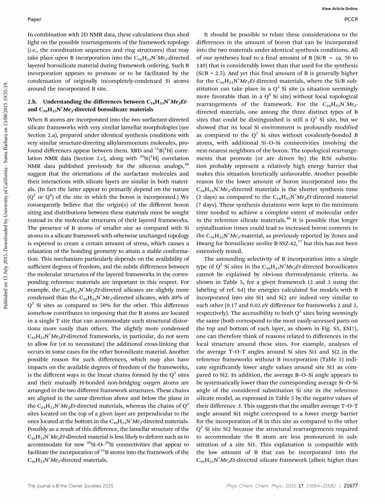
The astounding selectivity of B incorporation into a singletype of Q3 Si sites in the C16H33N+Me2Et-directed borosilicatescannot be explained by obvious thermodynamic criteria. Asshown in Table 5, for a given framework (2 and 3 using thelabeling of ref. 64) the energies calculated for models with Bincorporated into site Si1 and Si2 are indeed very similar toeach other (0.17 and 0.02 eV difference for frameworks 2 and 3,respectively). The accessibility to both Q3 sites being seeminglythe same (both correspond to the most easily-accessed parts onthe top and bottom of each layer, as shown in Fig. S5, ESI†),one can therefore think of reasons related to differences in thelocal structure around these sites. For example, analyses ofthe average T–O–T angles around Si sites Si1 and Si2 in thereference frameworks without B incorporation (Table 5) indi-cate significantly lower angle values around site Si1 as com-pared to Si2. In addition, the average B–O–Si angle appears tobe systematically lower than the corresponding average Si–O–Siangle of the considered substitution Si site in the referencesilicate model, as expressed in Table 5 by the negative values oftheir difference D. This suggests that the smaller average T–O–Tangle around Si1 might correspond to a lower energy barrierfor the incorporation of B in this site as compared to the otherQ3 Si site Si2 because the structural rearrangements requiredto accommodate the B atom are less pronounced in sub-stitution of a site Si1. This explanation is compatible withthe low amount of B that can be incorporated into theC16H33N+Me2Et-directed silicate framework (albeit higher than
Paper PCCP
Publ
ishe
d on
15
July
201
5. D
ownl
oade
d by
Uni
vers
ity o
f C
alif
orni
a -
Sant
a B
arba
ra o
n 13
/08/
2015
19:
55:1
9.
View Article Online
21678 | Phys. Chem. Chem. Phys., 2015, 17, 21664--21682 This journal is© the Owner Societies 2015
in the C16H33N+Me3-directed framework), which indicates arelatively high energy barrier during the synthesis, and thus akinetically-limited process.
3. Conclusions
We have established the B site distributions in the two chemi-cally and structurally related C16H33N+Me3- and C16H33N+Me2Et-directed layered borosilicates by using advanced solid-state NMRtechniques, in conjunction with DFT calculations. The resultsand analyses reveal that B atoms are incorporated into differenttypes of framework sites in the C16H33N+Me3-directed boro-silicates, and induce in some cases local topological rearrange-ments of nearby Si sites that tend to be more polymerized thanin the reference silicate framework. In C16H33N+Me2Et-directedborosilicates, in contrast, B atoms are shown to be selectivelyincorporated into one type of Q3 29Si sites without topologicalmodifications of the framework. Furthermore, the distorted localenvironments near B sites in C16H33N+Me2Et-directed boro-silicates appear to be similar throughout the framework, resultingin a degree of molecular order that approaches that of crystallinestructures, though without long-range periodicity. The ability ofNMR combined with DFT calculations to distinguish betweentopological and subtle geometrical disorder resulting from achemical disorder in otherwise molecularly-ordered solids maybe a key to understand the origins of many advanced materialsproperties.23 In particular, the types and distributions of orderand disorder near framework B sites in the borosilicate frame-works studied here might well be correlated with the reaction andother material properties of borosilicates, as is now well-established for aluminosilicate zeolites.12 While there is littleevidence that this is also true for borosilicates, which havereceived less attention, some studies nevertheless revealed dif-ferent conversion rates and selectivities for borosilicate zeolitesdepending on the Si/B ratios,78 which may be interpreted aschanges in the B siting among the different framework sites asthe B content changes. The molecular-level insights into B sitedistributions in the two surfactant-directed borosilicates areexpected to guide rational syntheses of borosilicate zeolitecatalysts with controlled B site distributions.
4. Materials and methodsSyntheses of materials
Cetyltrimethylammonium bromide (C16H33Me3NBr, Z96.0%,Sigma-Aldrich), cetyldimethylethylammonium bromide (C16H33-Me2EtNBr, Z98%, Sigma-Aldrich), tetramethylammonium hydro-xide (TMAOH, 25 wt% in water, Sigma-Aldrich), boric acid(Sigma-Aldrich), hydrofluoric acid (HF, 48 wt% in water, Sigma-Aldrich), nitric acid (HNO3, ACS reagent and 70%), amorphoussilica (SiO2, CAB-O-SIL M5 scintillation grade, ACROS ORGANICS)and methanol (ACS grade, VWRs) were purchased and directlyused without any further purification. 99% 29Si-enriched SiO2
was purchased from CortecNet (France). Syntheses of layeredsurfactant-directed borosilicates follow the molar compositionof 1.0SiO2 : 0.2B2O3 : 0.7TMAOH : 113.4H2O : 9.9CH3OH : 0.7 sur-factants (either C16H33Me3NBr or C16H33Me2EtNBr). Surfactantswere dissolved in deionized water. TMAOH and CH3OH weresubsequently added and the solution stirred for 30 min, afterwhich silica precursors (either SiO2 or recondensed 29SiO2) wereadded, and the reaction media stirred for a week. Boric acid wasthen added for 2 h to obtain synthesis gels, which were trans-ferred into a Teflont-lined Parrt 4745 stainless-steel reactor,well-sealed and heated at 135 1C under static conditions for2 (C16H33N+Me3-directed borosilicates) and 7 days (C16H33N+Me2Et-directed borosilicates). These crystallization times correspondto the minimal duration needed to obtain complete extents ofmolecular order for the corresponding reference silicate struc-tures of both materials.46 After the hydrothermal treatment, theas-synthesized layered surfactant-directed borosilicates werecollected using vacuum filtration and washed with deionized water.The products were dried at 90 1C overnight before characterization.
Recondensed 29SiO2 was prepared by dissolving 29Si-enrichedSiO2 in 1 M TMAOH solution (pH B 14) under reflux at 95 1C andstirring conditions for 19 days. The 29Si-enriched silica wassubsequently recovered by adding a concentrated HBr acidsolution to obtain precipitated gels (pH of 7–8), which weresubsequently collected by vacuum filtration. The precipitatedgels were purified by deionized water, high-speed centrifugation,and removal of excess water. The purified silica source (designatedas recondensed 29SiO2) was dried at 90 1C for several days prior tosyntheses of borosilicates.
Table 5 Local structure analyzes around (potential) B incorporation site in the reference silicate and borosilicate framework models of theC16H33N+Me2Et-directed material
Model composition Reference framework B incorporation site Energy (eV)
Average T–O–T angle
Name Value (1) Da (1)
[Si10O20(OH)2]2� 2 �11436.09 Si1–O–Si 143.5
Si2–O–Si 151.83 �11435.99 Si1–O–Si 144.6
Si2–O–Si 151.8
[BSi39O80(OH)8]8� 2 Si1 �45652.59 B–O–Si 138.8 �4.7Si2 �45652.46 B–O–Si 150.1 �1.7
3 Si1 �45652.10 B–O–Si 138.8 �5.8Si2 �45652.08 B–O–Si 140.7 �11.0
a D is the difference between the average B–O–Si angle and the corresponding average Si–O–Si angle in the reference structure (without Bincorporation).
PCCP Paper
Publ
ishe
d on
15
July
201
5. D
ownl
oade
d by
Uni
vers
ity o
f C
alif
orni
a -
Sant
a B
arba
ra o
n 13
/08/
2015
19:
55:1
9.
View Article Online
This journal is© the Owner Societies 2015 Phys. Chem. Chem. Phys., 2015, 17, 21664--21682 | 21679
Elemental analyses
Bulk Si/B ratios were obtained using inductively coupled plasma(ICP) analysis (Thermo iCAP 6300 model). Before ICP analysis,the as-synthesized layered materials were calcined at 550 1C for12 h to remove organic surfactants, and the resulting calcinedmaterials were dissolved with 2 wt% HF and 3 wt% HNO3 acidsolution under vigorous stirring conditions for several days. TheCHN results were provided by the analytical lab in the MarineScience Institute (MSI), UCSB, using the CEC440HA model fromExeter Analytical, Inc.
Solid-state NMR
Solid-state one-dimensional (1D) 11B, 29Si and two-dimensional(2D) 11B{1H} HETCOR NMR experiments were performed on aBruker Avance (III) 750 and 400 NMR spectrometers operatingat 17.6 (1H, 11B, and 29Si Larmor frequencies of 750.12, 240.66,and 149.01 MHz, respectively) and 9.4 T (1H, 11B, and 29Sifrequencies of 400.17, 128.38, and 79.49 MHz, respectively).The 1D 29Si{1H} CP-MAS experiments were collected at roomtemperature, at 17.6 T and at 10 kHz under conditions of magicangle spinning (MAS) using a 4 mm probe head, with a cross-polarization (CP) contact time of 8 ms and a recycle delay of 2 s,with 4k transients for the natural abundance sample and128 scans for the 29Si enriched sample. 11B echo-MAS experi-ments were performed at 17.6 T, at a MAS frequency of 14 kHzusing a recycling delay of 2 s, with a double frequency sweep(DFS)79 preparation sequence to increase the signal. Hetero-nuclear 1H decoupling at a nutation frequency of 50 kHz usingSPINAL6480 was utilized during acquisition for both 29Si and11B NMR experiments. Transverse dephasing time measure-ments were performed with 7 increments to obtain a seriesof half-echo delays between 0 and 12 ms, each collected with1024 scans. Heteronuclear 1H decoupling (SPINAL64) at anutation frequency of 60 kHz was alternatively turned on andoff during the echo (and kept on during the acquisition).
Two-dimensional (2D) 11B{1H} HETCOR NMR spectra werecollected at room temperature at 17.6 T and under MASconditions of 14 kHz using a 4 mm probe head. The magnetiza-tion was transferred from 1H to 11B by using adiabatic passagethrough Hartmann–Hahn condition.81 CP contact times of 1 and0.1 ms were used for the C16H33N+Me3- and C16H33N+Me2Et-directed layered borosilicates, respectively. The signal in the2D 1H dimension was accumulated over 96 increments with176 transients each for the C16H33N+Me3-directed material and128 increments with 64 transients each for the C16H33N+Me2Et-directed material. Heteronuclear 1H decoupling at a nutationfrequency of 70 kHz was applied during acquisition. Bothspectra were collected using a repetition delay of 2 s.
Two-dimensional 11B{29Si} dipolar- and J-mediated HMQCspectra were collected at 9.4 T on materials synthesized with29Si enrichment, at a MAS frequency of 10 kHz (using 3.2 mmtriple-resonance probe head). The heteronuclear dipolar couplingsbetween 11B and 29Si species were reintroduced in dipolar-mediated 11B{29Si} HMQC by means of a R42
1 symmetry-baseddipolar recoupling82–85 scheme at a 29Si nutation frequency of
20 kHz (2nR). The recoupling durations were set to 6 ms(10 symmetry cycles of 6 rotor periods each) before and afterthe evolution period. The second 29Si dimension was collectedwith 96 increments, with 1024 transients each, and a repetitiondelay of 2.17 s (total experimental duration of 61 hours). Thehalf-echo delay before and after the evolution period in the11B{29Si} J-mediated HMQC86 experiments was optimized experimen-tally to 10 and 12.5 ms for the C16H33N+Me3- and C16H33N+Me2Et-directed layered borosilicates, respectively. The indirect dimensionswere collected with 32 increments (2304 scans each) for theformer material and 96 increments for the latter (768 transientseach). Recycling delays of 3 second for both materials ledto experimental durations of 62 and 63 hours, respectively.Heteronuclear 1H decoupling with the SPINAL64 sequence at anutation frequency of ca. 60 kHz was applied during the wholesequence. NMR 29Si and 11B chemical shifts were referenced totetra methyl silane (TMS) and BF3OEt2, respectively.
Error calculations for the transverse dephasing time measure-ments were conducted using a Monte Carlo approach, by repeat-ing the same fit on 512 sets of data points generated by addingrandom noise to the experimental data set. The standarddeviation of the added random noise was fixed to the standarddeviation between the experimental points and the best fit. Thereported errors correspond to the standard deviation of thefitted data over the 512 fits.
X-ray diffraction
The mesostructures and local periodic orderings were charac-terized using small-angle (SAXS) and wide-angle (WAXS) X-raydiffractions. SAXS patterns were collected using a Rigaku SMARTlab diffractometer and Cu Ka radiation (l = 1.5405 Å) generated at44 kV and 40 mA. The scanning angle range of a SAXS pattern wasfrom 0.5 to 101 2y and the step size was set to 0.51 min�1. WAXSpatterns were collected using a Philips XPERT Pro diffractometerand Cu Ka radiation (l = 1.5405 Å) generated at 45 kV and 40 mA.The materials were scanned at a step size of 41 min�1 between 2yangle ranges from 10 to 451.
DFT calculations
DFT calculations were conducted using CASTEP,87 a code basedon Density Functional Theory that uses a plane-wave approachand periodic boundary conditions. Geometry optimizations wereconducted using PBE as an exchange correlation functional,88 acut-off energy of 650 eV, and the default ‘‘on-the-fly’’ ‘‘ultrasoft’’pseudopotentials89 of Materials Studio (see pseudopotentialdetails in ESI,† Table S4) with convergence thresholds of10�5 eV per atom for the total energy, 3 � 10�2 eV Å�1 for themaximum ionic force, and 10�3 Å for the maximum ionicdisplacement. During the geometry optimization, unit cellswere kept frozen, while all the atoms inside were allowed to relaxin order to minimize both the forces on the atoms and on the unitcell. Depending on the model size, different Monkhorst–Pack90
(MP) grids were used to sample the Brillouin zone so as to give ak-spacing less than 0.04 �1 in the a, b, c directions. Forexample, a 4 � 4 � 1 MP grid is used when calculation was madeon one unit cell (10 or 8 Si atoms depending on the material),
Paper PCCP
Publ
ishe
d on
15
July
201
5. D
ownl
oade
d by
Uni
vers
ity o
f C
alif
orni
a -
Sant
a B
arba
ra o
n 13
/08/
2015
19:
55:1
9.
View Article Online
21680 | Phys. Chem. Chem. Phys., 2015, 17, 21664--21682 This journal is© the Owner Societies 2015
whereas MP grids of size 4 � 2 � 1, 2 � 4 � 1, 2 � 2 � 1, and3 � 1 � 1 were used for the 1 � 2 � 1, 2 � 1 � 1, 2 � 2 � 1, and1 � 3 � 1 supercells, respectively.
Calculations of NMR shielding values were performed usingthe Gauge Including Projector Augmented Wave approach91
(GIPAW) method implemented in CASTEP using the same condi-tions for cut-off energy and MP grid as for geometry optimizations.Reliable absolute chemical shift values may be obtained fromcorrelation plots between experimental isotropic chemical shiftsand calculated isotropic chemical shielding for an appropriateseries of reference compounds in order to cover a large domain ofchemical shifts for each type of nuclei. Here, we used for 29Si and11B chemical shift calculations the compounds listed in Table S3(ESI†), which gave rise to the correlation plots shown in Fig. S7(ESI†). The correlation equations were: diso(ppm) = �0.920 siso +288.45 for 29Si, and diso(ppm) = �1.004 siso + 95.31 for 11B.
Acknowledgements
This work was supported by an international collaborativegrant between the U.S. National Science Foundation (NSF)(CHE-0924654) and the French ANR (ANR-09-BLAN-0383-CSD3 ‘‘ALUBOROSIL’’). Portions of this work were carried out usingthe Central Facilities of the UCSB Materials Research Laboratorysupported by the MRSEC Program of the U.S. NSF under awardDMR-1121053; the MRL Central Facilities are a member of theNSF-funded Materials Research Facilities Network (www.mrfn.org).For DFT calculations, we thank the ‘‘Centre de Calcul Scientifiqueen region Centre’’ (Orleans, France), CINES for access to thesupercomputer JADE (Project # c2011096604), and the FrenchANR (ANR-11-MONU-003 ‘‘ExaviZ’’) for funding.
References
1 K. Tanabe and W. F. Holderich, Appl. Catal., A, 1999, 181,399–434.
2 M. Borja and P. K. Dutta, Nature, 1993, 362, 43–45.3 M. Iwamoto, H. Yahiro, N. Mizuno, W. X. Zhang, Y. Mine,
H. Furukawa and S. Kagawa, J. Phys. Chem., 1992, 96, 9360–9366.4 D. Barthomeuf, Catal. Rev.: Sci. Eng., 1996, 38, 521–612.5 S. M. Kuznicki, V. A. Bell, S. Nair, H. W. Hillhouse, R. M.
Jacubinas, C. M. Braunbarth, B. H. Toby and M. Tsapatsis,Nature, 2001, 412, 720–724.
6 S. H. Joo, S. J. Choi, I. Oh, J. Kwak, Z. Liu, O. Terasaki andR. Ryoo, Nature, 2001, 412, 169–172.
7 J. Choi, H.-K. Jeong, M. A. Snyder, J. A. Stoeger, R. I. Maseland M. Tsapatsis, Science, 2009, 325, 590–593.
8 K. Varoon, X. Zhang, B. Elyassi, D. D. Brewer, M. Gettel,S. Kumar, J. A. Lee, S. Maheshwari, A. Mittal, C.-Y. Sung,M. Cococcioni, L. F. Francis, A. V. McCormick, K. A.Mkhoyan and M. Tsapatsis, Science, 2011, 333, 72–75.
9 R. Bermejo-Deval, R. S. Assary, E. Nikolla, M. Moliner,Y. Roman-Leshkov, S. J. Hwang, A. Palsdottir, D. Silverman,R. F. Lobo, L. A. Curtiss and M. E. Davis, Proc. Natl. Acad. Sci.U. S. A., 2012, 109, 9727–9732.
10 J. Jae, G. A. Tompsett, A. J. Foster, K. D. Hammond, S. M.Auerbach, R. F. Lobo and G. W. Huber, J. Catal., 2011, 279,257–268.
11 T. Willhammar, J. Sun, W. Wan, P. Oleynikov, D. Zhang,X. Zou, M. Moliner, J. Gonzalez, C. Martınez, F. Rey andA. Corma, Nat. Chem., 2012, 4, 188–194.
12 J. Dedecek, Z. Sobalık and B. Wichterlova, Catal. Rev., 2012,54, 135–223.
13 Y. Roman-Leshkov, M. Moliner and M. E. Davis, J. Phys.Chem. C, 2011, 115, 1096–1102.
14 A. B. Pinar, C. Marquez-Alvarez, M. Grande-Casas and J. Perez-Pariente, J. Catal., 2009, 263, 258–265.
15 C. A. Hijar, R. M. Jacubinas, J. Eckert, N. J. Henson,P. J. Hay and K. C. Ott, J. Phys. Chem. B, 2000, 104,12157–12164.
16 C. Lamberti, S. Bordiga, A. Zecchina, G. Artioli, G. Marraand G. Spano, J. Am. Chem. Soc., 2001, 123, 2204–2212.
17 P. F. Henry, M. T. Weller and C. C. Wilson, J. Phys. Chem. B,2001, 105, 7452–7458.
18 M. Milanesio, C. Lamberti, R. Aiello, F. Testa, M. Piana andD. Viterbo, J. Phys. Chem. B, 2000, 104, 9951–9953.
19 L. Palin, C. Lamberti, A. Kvick, F. Testa, R. Aiello,M. Milanesio and D. Viterbo, J. Phys. Chem. B, 2003, 107,4034–4042.
20 J. Shin, D. S. Bhange, M. A. Camblor, Y. Lee, W. J. Kim,I. S. Nam and S. B. Hong, J. Am. Chem. Soc., 2011, 133,10587–10598.
21 J. A. van Bokhoven, T.-L. Lee, M. Drakopoulos, C. Lamberti,S. Thiesz and J. Zegenhagen, Nat. Mater., 2008, 7, 551–555.
22 E. Veron, M. N. Garaga, D. Pelloquin, S. Cadars, M. Suchomel,E. Suard, D. Massiot, V. Montouillout, G. Matzen and M. Allix,Inorg. Chem., 2013, 52, 4250–4258.
23 D. Massiot, R. J. Messinger, S. Cadars, M. Deschamps,V. Montouillout, N. Pellerin, E. Veron, M. Allix, P. Florianand F. Fayon, Acc. Chem. Res., 2013, 46, 1975–1984.
24 C. A. Fyfe, J. L. Bretherton and L. Y. Lam, J. Am. Chem. Soc.,2001, 123, 5285–5291.
25 S. Sklenak, J. Dedecek, C. B. Li, B. Wichterlova, V. Gabova,M. Sierka and J. Sauer, Angew. Chem., Int. Ed., 2007, 46,7286–7289.
26 O. H. Han, C. S. Kim and S. B. Hong, Angew. Chem., Int. Ed.,2002, 41, 469–472.
27 J. Dedecek, L. Capek, P. Sazama, Z. Sobalik and B. Wichterlova,Appl. Catal., A, 2011, 391, 244–253.
28 J. Dedecek, V. Balgova, V. Pashkova, P. Klein and B. Wichterlova,Chem. Mater., 2012, 24, 3231–3239.
29 P. Sazama, J. Dedecek, V. Gabova, B. Wichterlova, G. Spotoand S. Bordiga, J. Catal., 2008, 254, 180–189.
30 C. Baerlocher, D. Xie, L. B. McCusker, S. J. Hwang, I. Y.Chan, K. Ong, A. W. Burton and S. I. Zones, Nat. Mater.,2008, 7, 631–635.
31 T. Willhammar, A. W. Burton, Y. Yun, J. Sun, M. Afeworki,K. G. Strohmaier, H. Vroman and X. Zou, J. Am. Chem. Soc.,2014, 136, 13570–13573.
32 D. Xie, L. B. McCusker, C. Baerlocher, L. Gibson, A. W. Burtonand S. J. Hwang, J. Phys. Chem. C, 2009, 113, 9845–9850.
PCCP Paper
Publ
ishe
d on
15
July
201
5. D
ownl
oade
d by
Uni
vers
ity o
f C
alif
orni
a -
Sant
a B
arba
ra o
n 13
/08/
2015
19:
55:1
9.
View Article Online
This journal is© the Owner Societies 2015 Phys. Chem. Chem. Phys., 2015, 17, 21664--21682 | 21681
33 A. Grunewald-Luke, H. Gies, U. Muller, B. Yilmaz, H. Imai,T. Tatsumi, B. Xie, F.-S. Xiao, X. Bao, W. Zhang andD. De Vos, Microporous Mesoporous Mater., 2012, 147,102–109.
34 P. S. Neuhoff, S. Kroeker, L. S. Du, T. Fridriksson andJ. F. Stebbins, Am. Mineral., 2002, 87, 1307–1320.
35 S. B. Hong, S.-H. Lee, C.-H. Shin, A. J. Woo, L. J. Alvarez,C. M. Zicovich-Wilson and M. A. Camblor, J. Am. Chem. Soc.,2004, 126, 13742–13751.
36 G. Engelhardt and D. Michel, High-resolution solid-stateNMR of silicates and zeolites, Wiley, 1987.
37 K. J. D. Mackenzie and M. E. Smith, multinuclear solid-stateNMR of inorganic materials, Pergamon Press, Oxford, 2002.
38 H. K. Jeong, S. Nair, T. Vogt, L. C. Dickinson andM. Tsapatsis, Nat. Mater., 2003, 2, 53–58.
39 T. Ikeda, Y. Akiyama, Y. Oumi, A. Kawai and F. Mizukami,Angew. Chem., Int. Ed., 2004, 43, 4892–4896.
40 T. Ikeda, S. Kayamori and F. Mizukami, J. Mater. Chem.,2009, 19, 5518–5525.
41 L. Palin, G. Croce, D. Viterbo and M. Milanesio, Chem.Mater., 2011, 23, 4900–4909.
42 B. Yilmaz, U. Muller, B. Tijsebaert, D. De Vos, B. Xie,F. S. Xiao, H. Gies, W. P. Zhang, X. H. Bao, H. Imai andT. Tatsumi, Chem. Commun., 2011, 47, 1812–1814.
43 Z. Li, B. Marler and H. Gies, Chem. Mater., 2008, 20,1896–1901.
44 B. Marler and H. Gies, Eur. J. Mineral., 2012, 24, 405–428.45 W. J. Roth, P. Nachtigall, R. E. Morris and J. Cejka, Chem.
Rev., 2014, 114, 4807–4837.46 S. C. Christiansen, D. Y. Zhao, M. T. Janicke, C. C. Landry,
G. D. Stucky and B. F. Chmelka, J. Am. Chem. Soc., 2001, 123,4519–4529.
47 N. Hedin, R. Graf, S. C. Christiansen, C. Gervais, R. C.Hayward, J. Eckert and B. F. Chmelka, J. Am. Chem. Soc.,2004, 126, 9425–9432.
48 Y. D. Xia and R. Mokaya, Microporous Mesoporous Mater.,2006, 94, 295–303.
49 Y. D. Xia and R. Mokaya, J. Phys. Chem. B, 2006, 110,9122–9131.
50 G. Coudurier, A. Auroux, J. C. Vedrine, R. D. Farlee, L. Abramsand R. D. Shannon, J. Catal., 1987, 108, 1–14.
51 R. Millini, G. Perego and G. Bellussi, Top. Catal., 1999, 9,13–34.
52 R. A. Van Nordstrand, D. S. Santilli and S. I. Zones, inMolcular Sieves, ed. M. L. Ocelli and H. E. Robson, Synthesisof Microporous Materials, New York, 1992, vol. 1, p. 373.
53 S. I. Zones, A. Benin, S.-J. Hwang, D. Xie, S. Elomari andM.-F. Hsieh, J. Am. Chem. Soc., 2014, 136, 1462–1471.
54 D. Sakellariou and L. Emsley, in Encyclopedia of NuclearMagnetic Resonance, ed. D. M. Grant and R. K. Harris, Wiley,London, 2002, vol. 9, pp. 196–211.
55 D. Massiot, F. Fayon, M. Deschamps, S. Cadars, P. Florian,V. Montouillout, N. Pellerin, J. Hiet, A. Rakhmatullin andC. Bessada, C. R. Chim., 2010, 13, 117–129.
56 C. A. Fyfe, H. Gies, Y. Feng and G. T. Kokotailo, Nature,1989, 341, 223–225.
57 C. A. Fyfe, H. Gies and Y. Feng, J. Chem. Soc., Chem.Commun., 1989, 1240–1242.
58 C. A. Fyfe, H. Gies and Y. Feng, J. Am. Chem. Soc., 1989, 111,7702–7707.
59 S. Cadars, D. H. Brouwer and B. F. Chmelka, Phys. Chem.Chem. Phys., 2009, 11, 1825–1837.
60 C. A. Fyfe, K. C. Wongmoon, Y. Huang, H. Grondey andK. T. Mueller, J. Phys. Chem., 1995, 99, 8707–8716.
61 M. Deschamps, F. Fayon, J. Hiet, G. Ferru, M. Derieppe,N. Pellerin and D. Massiot, Phys. Chem. Chem. Phys., 2008,10, 1298–1303.
62 P. Florian, E. Veron, T. F. G. Green, J. R. Yates andD. Massiot, Chem. Mater., 2012, 24, 4068–4079.
63 C. A. Fyfe, Y. Feng, H. Grondey, G. T. Kokotailo and H. Gies,Chem. Rev., 1991, 91, 1525–1543.
64 D. H. Brouwer, S. Cadars, J. Eckert, Z. Liu, O. Terasaki andB. F. Chmelka, J. Am. Chem. Soc., 2013, 135, 5641–5655.
65 S. Cadars, M. Allix, D. H. Brouwer, R. Shayib, M. Suchomel,A. W. Burton, M. N. Garaga, A. I. Rakhmatullin, S. I. Zones,D. Massiot and B. F. Chmelka, Chem. Mater, 2014, 26,6994–7008.
66 P. Florian, F. Fayon and D. Massiot, J. Phys. Chem. C, 2009,113, 2562–2572.
67 D. Massiot, F. Fayon, V. Montouillout, N. Pellerin, J. Hiet,C. Roiland, P. Florian, J. P. Coutures, L. Cormier andD. R. Neuville, J. Non-Cryst. Solids, 2008, 354, 249–254.
68 J. Hiet, M. Deschamps, N. Pellerin, F. Fayon and D. Massiot,Phys. Chem. Chem. Phys., 2009, 11, 6935–6940.
69 G. De Paepe, N. Giraud, A. Lesage, P. Hodgkinson,A. Bockmann and L. Emsley, J. Am. Chem. Soc., 2003, 125,13938–13939.
70 G. De Paepe, A. Lesage, S. Steuernagel and L. Emsley,ChemPhysChem, 2004, 5, 869–875.
71 S. Vortmann, J. Rius, S. Siegmann and H. Gies, J. Phys.Chem. B, 1997, 101, 1292–1297.
72 I. Wolf, H. Gies and C. A. Fyfe, J. Phys. Chem. B, 1999, 103,5933–5938.
73 N. Tsunoji, T. Ikeda, Y. Ide, M. Sadakane and T. Sano,J. Mater. Chem., 2012, 22, 13682–13690.
74 S. Cadars, N. Mifsud, A. Lesage, J. D. Epping, N. Hedin,B. F. Chmelka and L. Emsley, J. Phys. Chem. C, 2008, 112,9145–9154.
75 L. S. Du and J. F. Stebbins, J. Non-Cryst. Solids, 2003, 315,239–255.
76 C. Baerlocher, L. B. McCusker and D. H. Olson, Atlas ofZeolite Framework Types, Elsevier, Amsterdam, 2007.
77 S. I. Zones and S. J. Hwang, Microporous Mesoporous Mater.,2003, 58, 263–277.
78 A. Boghoz, M. Soltanieh, R. Mondegarian and M. Karbalaee,Ind. Eng. Chem. Res., 1998, 37, 2378–2382.
79 D. Iuga and A. P. M. Kentgens, J. Magn. Reson., 2002, 158,65–72.
80 B. M. Fung, A. K. Khitrin and K. Ermolaev, J. Magn. Reson.,2000, 142, 97–101.
81 S. Hediger, B. H. Meier, N. D. Kurur, G. Bodenhausen andR. R. Ernst, Chem. Phys. Lett., 1994, 223, 283–288.
Paper PCCP
Publ
ishe
d on
15
July
201
5. D
ownl
oade
d by
Uni
vers
ity o
f C
alif
orni
a -
Sant
a B
arba
ra o
n 13
/08/
2015
19:
55:1
9.
View Article Online
21682 | Phys. Chem. Chem. Phys., 2015, 17, 21664--21682 This journal is© the Owner Societies 2015
82 M. Carravetta, M. Eden, X. Zhao, A. Brinkmann and M. H.Levitt, Chem. Phys. Lett., 2000, 321, 205–215.
83 A. Brinkmann and M. H. Levitt, J. Chem. Phys., 2001, 115,357–384.
84 A. Brinkmann and A. P. M. Kentgens, J. Am. Chem. Soc.,2006, 128, 14758–14759.
85 B. Hu, J. Trebosc and J. P. Amoureux, J. Magn. Reson., 2008,192, 112–122.
86 A. Lesage, D. Sakellariou, S. Steuernagel and L. Emsley,J. Am. Chem. Soc., 1998, 120, 13194–13201.
87 S. J. Clark, M. D. Segall, C. J. Pickard, P. J. Hasnip, M. J. Probert,K. Refson and M. C. Payne, Z. Kristallogr., 2005, 220, 567–570.
88 J. P. Perdew, K. Burke and M. Ernzerhof, Phys. Rev. Lett.,1996, 77, 3865–3868.
89 D. Vanderbilt, Phys. Rev. B: Condens. Matter Mater. Phys.,1990, 41, 7892–7895.
90 H. J. Monkhorst and J. D. Pack, Phys. Rev. B: Solid State,1976, 13, 5188–5192.
91 C. J. Pickard and F. Mauri, Phys. Rev. B: Condens. MatterMater. Phys., 2001, 63, 245101.
PCCP Paper
Publ
ishe
d on
15
July
201
5. D
ownl
oade
d by
Uni
vers
ity o
f C
alif
orni
a -
Sant
a B
arba
ra o
n 13
/08/
2015
19:
55:1
9.
View Article Online