Embed Size (px)
Citation preview

Local Area Networks

Why High Speed LANs?• Office LANs used to provide basic connectivity
—Connecting PCs and terminals to mainframes and midrange systems that ran corporate applications
—Providing workgroup connectivity at departmental level—Traffic patterns light
• Emphasis on file transfer and electronic mail
• Speed and power of PCs has risen—Graphics-intensive applications and GUIs
• MIS organizations recognize LANs as essential —Began with client/server computing
• Now dominant architecture in business environment• Intranetworks• Frequent transfer of large volumes of data

Applications Requiring High Speed LANs• Centralized server farms
—User needs to draw huge amounts of data from multiple centralized servers
—E.g. Color publishing• Servers contain tens of gigabytes of image data• Downloaded to imaging workstations
• Power workgroups• Small number of cooperating users
—Draw massive data files across network—E.g. Software development group testing new software
version or computer-aided design (CAD) running simulations
• High-speed local backbone—Processing demand grows—LANs proliferate at site—High-speed interconnection is necessary

Protocol Architecture• Lower layers of OSI model• IEEE 802 reference model• Physical• Logical link control (LLC)• Media access control (MAC)
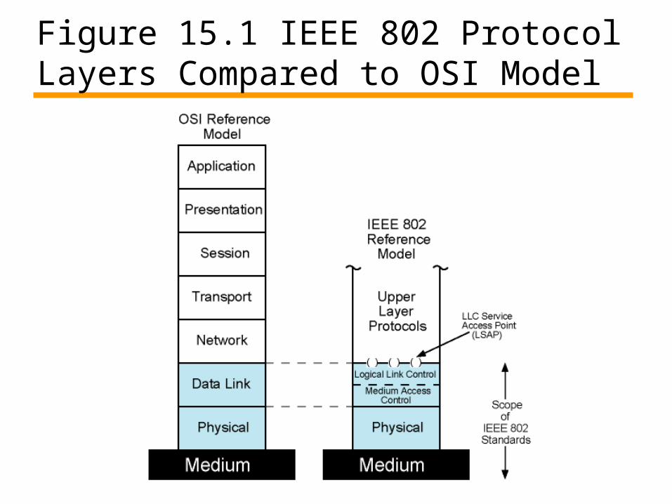
Figure 15.1 IEEE 802 Protocol Layers Compared to OSI Model

802 Layers - Physical• Encoding/decoding• Preamble generation/removal• Bit transmission/reception• Transmission medium and topology

802 Layers -Logical Link Control• Interface to higher levels• Flow and error control

Figure 15.2 LAN Protocols in Context

Logical Link Control • Transmission of link level PDUs between
two stations• Must support multi-access, shared
medium• Relieved of some link access details by
MAC layer• Addressing involves specifying source and
destination LLC users—Referred to as service access points (SAP)—Typically higher level protocol

LLC Services• Based on HDLC• Unacknowledged connectionless service• Connection mode service• Acknowledged connectionless service


MAC Frame Format• MAC layer receives data from LLC layer• MAC control• Destination MAC address• Source MAC address• LLC PDU – data from next layer up• CRC• MAC layer detects errors and discards
frames• LLC optionally retransmits unsuccessful
frames

Figure 15.3 LLC PDU in a Generic MAC Frame Format

Ethernet• Developed by Xerox• IEEE 802.3• Classical Ethernet
—10 Mbps—Bus topology—CSMA/CD (carrier sense multiple access with
collision detection)
Bus Topology• Stations attach to linear transmission medium (bus)
— Via a tap• Full-duplex between station and tap• Transmission propagates length of medium in both directions• Received by all other stations• Ends of bus terminated
— Absorbs signal• Need to show for whom transmission is intended• Need to regulate transmission
— If two stations attempt to transmit at same time, signals will overlap and become garbled
— If one station transmits continuously access blocked for others• Transmit data in small blocks (frames)• Each station assigned unique address
— Destination address included in frame header

Figure 15.4 Frame Transmission on a Bus LAN

Tree Topology• Generalization of the bus topology.• There is no closed loops in the transmidium.• The tree layout begins at a point known as
‘headend’ where one or more cables start and ecah of these may have braches.
• The branches may have additional branches to allow more complex layouts.
• A transmission propagation from one station can be received by all other stations.

Problems….• For whom the transmission is intended?• Mechanism is needed to regulate the
transmission. e.g. Signal overlapping and signal will be
garbled.
What will be solutions ?????

Ring Topology• In a ring topology the network is consist of a set
of repeaters joined by point to point links in a closed loop.
• Why repeater?• Frames circulate around the ring in one direction
either clockwise or counterclockwise.• Each station is attached to network through a
repeater and can transmit and receive data on/from the network through that repeater.
• As a frame circulates pas all the other stations, the destination station recognizes its address an copies the frame to its local buffer as it goes by.
• The frame continues to circulate until it returns to the source station where it is removed.

Star Topology• In a star topology each station is directly
connected to a central node.• Typically each station attaches to the
central node via a point to point link one for transmission in each direction.
• Central node can be operated as a broadcast device or switching device….
• What if it’s a broadcast device…..?????
MAC(Medium Access Control)• Some means are needed to orderly access
the medium in a shared network.• Where and How….• Where refers to whether control is exercised
in a centralized or distributed fashion.• In a centralized fashion a controller is
designated….it controls all the stations and their access to the medium.
• In a decentralized network the stations collectively performs the medium access.its dynamic.

Continued……A centralized scheme has the certain
advantages…• It may afford greater control over access for
providing such things as priorities,overrides,and guaranteed capacity.
• It enables the use of relatively simple access logic at each station.
• It avoids problems of distributed coordination among peer entities.
Continued….The disadvantage of Centralized schemes….• It creates a single point of failure,that is
there is a point in the network if one point fails will cause the whole network to down.
• It may act as a bottleneck reducing performance.
The 2nd parameter ‘how’ is constrained by the topology and is a trade off among competing factors, including cost, performance and complexity.

CSMA/CD• With CSMA, collision occupies medium for
duration of transmission• Stations listen whilst transmitting
1. If medium idle, transmit, otherwise, step 2
2. If busy, listen for idle, then transmit3. If collision detected, jam then cease
transmission4. After jam, wait random time then start
from step 1

Figure 15.5CSMA/CD Operation

Figure 15.6 IEEE 802.3 Frame Format

10Mbps Specification (Ethernet)• <data rate><Signaling method><Max segment
length>
• 10Base5 10Base2 10Base-T 10Base-F
• Medium Coaxial Coaxial UTP 850nm fiber
• Signaling Baseband Baseband BasebandManchester
• Manchester ManchesterManchester On/Off
• Topology Bus Bus Star Star• Nodes 100 30 - 33
10BASE-T• Unshielded twisted pair (UTP) medium
—Also used for telephone
• Star-shaped topology—Stations connected to central point, (multiport repeater)—Two twisted pairs (transmit and receive)—Repeater accepts input on any one line and repeats it
on all other lines
• Link limited to 100 m on UTP—Optical fiber 500 m
• Central element of star is active element (hub) • Physical star, logical bus• Multiple levels of hubs can be cascaded

Figure 15.7 Two-Level Star Topology

Bridges• Ability to expand beyond single LAN• Provide interconnection to other
LANs/WANs• Use Bridge or router• Bridge is simpler
—Connects similar LANs—Identical protocols for physical and link layers—Minimal processing
• Router more general purpose—Interconnect various LANs and WANs—see later

Why Bridge?• Reliability• Performance• Security• Geography

Functions of a Bridge• Read all frames transmitted on one LAN
and accept those address to any station on the other LAN
• Using MAC protocol for second LAN, retransmit each frame
• Do the same the other way round

Figure 15.8 Bridge Operation

Bridge Design Aspects• No modification to content or format of frame• No encapsulation• Exact bitwise copy of frame• Minimal buffering to meet peak demand• Contains routing and address intelligence
—Must be able to tell which frames to pass—May be more than one bridge to cross
• May connect more than two LANs• Bridging is transparent to stations
—Appears to all stations on multiple LANs as if they are on one single LAN

Figure 15.9 LAN Hubs and Switches

Layer 2 Switches• Central hub acts as switch• Incoming frame from particular station
switched to appropriate output line• Unused lines can switch other traffic• More than one station transmitting at a
time• Multiplying capacity of LAN

Layer 2 Switch Benefits• No change to attached devices to convert bus
LAN or hub LAN to switched LAN• For Ethernet LAN, each device uses Ethernet MAC
protocol • Device has dedicated capacity equal to original
LAN—Assuming switch has sufficient capacity to keep up with
all devices—For example if switch can sustain throughput of 20
Mbps, each device appears to have dedicated capacity for either input or output of 10 Mbps
• Layer 2 switch scales easily—Additional devices attached to switch by increasing
capacity of layer 2
Types of Layer 2 Switch• Store-and-forward switch
—Accepts frame on input line—Buffers it briefly, —Then routes it to appropriate output line—Delay between sender and receiver—Boosts integrity of network
• Cut-through switch—Takes advantage of destination address appearing at
beginning of frame—Switch begins repeating frame onto output line as soon
as it recognizes destination address—Highest possible throughput —Risk of propagating bad frames
• Switch unable to check CRC prior to retransmission
Layer 2 Switch v Bridge• Layer 2 switch can be viewed as full-duplex hub• Can incorporate logic to function as multiport bridge• Bridge frame handling done in software• Switch performs address recognition and frame
forwarding in hardware• Bridge only analyzes and forwards one frame at a
time• Switch has multiple parallel data paths
—Can handle multiple frames at a time
• Bridge uses store-and-forward operation• Switch can have cut-through operation• Bridge suffered commercially
—New installations typically include layer 2 switches with bridge functionality rather than bridges

Problems with Layer 2 Switches (1)• As number of devices in building grows, layer 2
switches reveal some inadequacies• Broadcast overload• Lack of multiple links• Set of devices and LANs connected by layer 2
switches have flat address space—All users share common MAC broadcast address—If any device issues broadcast frame, that frame is
delivered to all devices attached to network connected by layer 2 switches and/or bridges
—In large network, broadcast frames can create big overhead
—Malfunctioning device can create broadcast storm• Numerous broadcast frames clog network

Problems with Layer 2 Switches (2)• Current standards for bridge protocols dictate no
closed loops—Only one path between any two devices—Impossible in standards-based implementation to provide
multiple paths through multiple switches between devices• Limits both performance and reliability.
• Solution: break up network into subnetworks connected by routers
• MAC broadcast frame limited to devices and switches contained in single subnetwork
• IP-based routers employ sophisticated routing algorithms —Allow use of multiple paths between subnetworks going
through different routers

Problems with Routers• Routers do all IP-level processing in software
—High-speed LANs and high-performance layer 2 switches pump millions of packets per second
—Software-based router only able to handle well under a million packets per second
• Solution: layer 3 switches—Implementpacket-forwarding logic of router in
hardware
• Two categories—Packet by packet —Flow based

Packet by Packet or Flow Based• Operates insame way as traditional router• Order of magnitude increase in performance
compared to software-based router• Flow-based switch tries to enhance
performance by identifying flows of IP packets—Same source and destination—Done by observing ongoing traffic or using a
special flow label in packet header (IPv6)—Once flow is identified, predefined route can be
established

Typical Large LAN Organization• Thousands to tens of thousands of devices• Desktop systems links 10 Mbps to 100 Mbps
— Into layer 2 switch
• Wireless LAN connectivity available for mobile users• Layer 3 switches at local network's core
—Form local backbone— Interconnected at 1 Gbps—Connect to layer 2 switches at 100 Mbps to 1 Gbps
• Servers connect directly to layer 2 or layer 3 switches at 1 Gbps
• Lower-cost software-based router provides WAN connection
• Circles in diagram identify separate LAN subnetworks• MAC broadcast frame limited to own subnetwork

Figure 15.10 Typical Premises Network Configuration

100Mbps Fast Ethernet• Use IEEE 802.3 MAC protocol and frame format• 100BASE-X use physical medium specifications
from FDDI—Two physical links between nodes
• Transmission and reception—100BASE-TX uses STP or Cat. 5 UTP
• May require new cable—100BASE-FX uses optical fiber—100BASE-T4 can use Cat. 3, voice-grade UTP
• Uses four twisted-pair lines between nodes• Data transmission uses three pairs in one direction at a
time
• Star-wire topology—Similar to 10BASE-T

100Mbps (Fast Ethernet)• 100Base-TX 100Base-FX 100Base-
T4
• 2 pair, STP 2 pair, Cat 5 UTP 2 optical fiber 4 pair, cat 3,4,5
• MLT-3 MLT-3 4B5B,NRZI 8B6T,NRZ

100BASE-X Data Rate and Encoding• Unidirectional data rate 100 Mbps over
single link —Single twisted pair, single optical fiber
• Encoding scheme same as FDDI —4B/5B-NRZI—Modified for each option

100BASE-X Media• Two physical medium specifications• 100BASE-TX
—Two pairs of twisted-pair cable—One pair for transmission and one for reception—STP and Category 5 UTP allowed—The MTL-3 signaling scheme is used
• 100BASE-FX—Two optical fiber cables—One for transmission and one for reception—Intensity modulation used to convert 4B/5B-NRZI code
group stream into optical signals—1 represented by pulse of light—0 by either absence of pulse or very low intensity pulse

100BASE-T4• Can not get 100 Mbps on single twisted
pair—Data stream split into three separate streams
• Each with an effective data rate of 33.33 Mbps
—Four twisted pairs used—Data transmitted and received using three
pairs—Two pairs configured for bidirectional
transmission

Figure 15.11 IEEE 802.3 100BASE-T Options
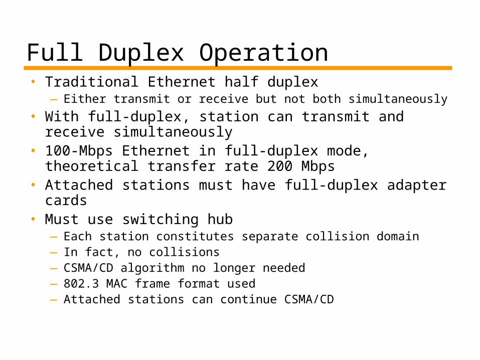
Full Duplex Operation• Traditional Ethernet half duplex
—Either transmit or receive but not both simultaneously
• With full-duplex, station can transmit and receive simultaneously
• 100-Mbps Ethernet in full-duplex mode, theoretical transfer rate 200 Mbps
• Attached stations must have full-duplex adapter cards
• Must use switching hub—Each station constitutes separate collision domain—In fact, no collisions—CSMA/CD algorithm no longer needed—802.3 MAC frame format used—Attached stations can continue CSMA/CD

Advantages/Disadvantages…• What are the advantages and
disadvantages of Bus,Tree, Ring and Star topoloy...
• What is extended star topology….??????

Gigabit Ethernet• Strategy same as Fast Ethernet• New medium and transmission
specification• Retains CSMA/CD protocol and frame
format• Compatible with 100BASE-T and 10BASE-T
—Migration path

Gigabit Ethernet – Physical• 1000Base-SX
—Short wavelength, multimode fiber
• 1000Base-LX—Long wavelength, Multi or single mode fiber
• 1000Base-CX—Copper jumpers <25m, shielded twisted pair
• 1000Base-T—4 pairs, cat 5 UTP
• Signaling - 8B/10B
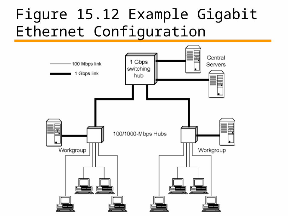
Figure 15.12 Example Gigabit Ethernet Configuration
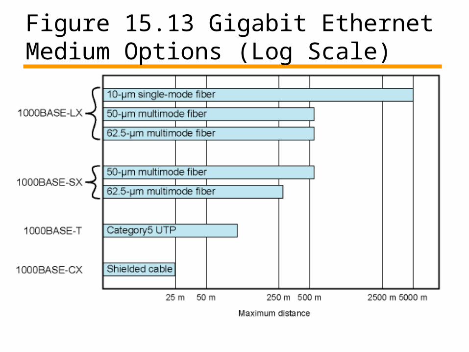
Figure 15.13 Gigabit Ethernet Medium Options (Log Scale)

10Gbps Ethernet - Uses• High-speed, local backbone interconnection between large-
capacity switches• Server farm• Campus wide connectivity• Enables Internet service providers (ISPs) and network
service providers (NSPs) to create very high-speed links at very low cost
• Allows construction of (MANs) and WANs— Connect geographically dispersed LANs between campuses or
points of presence (PoPs)
• Ethernet competes with ATM and other WAN technologies• 10-Gbps Ethernet provides substantial value over ATM

10Gbps Ethernet - Advantages• No expensive, bandwidth-consuming conversion
between Ethernet packets and ATM cells • Network is Ethernet, end to end• IP and Ethernet together offers QoS and traffic
policing approach ATM• Advanced traffic engineering technologies
available to users and providers• Variety of standard optical interfaces
(wavelengths and link distances) specified for 10 Gb Ethernet
• Optimizing operation and cost for LAN, MAN, or WAN

10Gbps Ethernet - Advantages• Maximum link distances cover 300 m to 40 km• Full-duplex mode only• 10GBASE-S (short):
— 850 nm on multimode fiber— Up to 300 m
• 10GBASE-L (long)— 1310 nm on single-mode fiber— Up to 10 km
• 10GBASE-E (extended)— 1550 nm on single-mode fiber— Up to 40 km
• 10GBASE-LX4:— 1310 nm on single-mode or multimode fiber— Up to 10 km— Wavelength-division multiplexing (WDM) bit stream across four
light waves

Figure 15.14 10-Gbps Ethernet Data Rate and Distance Options (Log Scale)

Wireless LANs• A wireless LAN uses wireless transmission
medium• Used to have high prices, low data rates,
occupational safety concerns, and licensing requirements
• Problems have been addressed• Popularity of wireless LANs has grown
rapidly
Applications - LAN Extension• Saves installation of LAN cabling• Eases relocation and other modifications to network
structure• However, increasing reliance on twisted pair cabling for
LANs —Most older buildings already wired with Cat 3 cable—Newer buildings are prewired with Cat 5
• Wireless LAN to replace wired LANs has not happened• In some environments, role for the wireless LAN
—Buildings with large open areas• Manufacturing plants, stock exchange trading floors, warehouses• Historical buildings• Small offices where wired LANs not economical
• May also have wired LAN—Servers and stationary workstations

Figure 15.15 Example Single-Cell Wireless LAN Configuration

Applications – Cross-Building Interconnect• Connect LANs in nearby buildings• Point-to-point wireless link• Connect bridges or routers• Not a LAN per se
—Usual to include this application under heading of wireless LAN

Applications - Nomadic Access• Link between LAN hub and mobile data
terminal —Laptop or notepad computer—Enable employee returning from trip to
transfer data from portable computer to server
• Also useful in extended environment such as campus or cluster of buildings—Users move around with portable computers—May wish access to servers on wired LAN

Applications – Ad Hoc Networking• Peer-to-peer network• Set up temporarily to meet some
immediate need• E.g. group of employees, each with laptop
or palmtop, in business or classroom meeting
• Network for duration of meeting

Wireless LAN Requirements• Same as any LAN
— High capacity, short distances, full connectivity, broadcast capability• Throughput: efficient use wireless medium• Number of nodes:Hundreds of nodes across multiple cells• Connection to backbone LAN: Use control modules to connect to
both types of LANs• Service area: 100 to 300 m• Low power consumption:Need long battery life on mobile stations
— Mustn't require nodes to monitor access points or frequent handshakes• Transmission robustness and security:Interference prone and easily
eavesdropped• Collocated network operation:Two or more wireless LANs in same
area• License-free operation• Handoff/roaming: Move from one cell to another• Dynamic configuration: Addition, deletion, and relocation of end
systems without disruption to users

IEEE 802.11 Architecture• MAC protocol and physical medium specification for
wireless LANs• Smallest building block is basic service set (BSS)
—Number of stations—Same MAC protocol—Competing for access to same shared wireless medium
• May be isolated or connect to backbone distribution system (DS) through access point (AP)—AP functions as bridge
• MAC protocol may be distributed or controlled by central coordination function in AP
• BSS generally corresponds to cell • DS can be switch, wired network, or wireless network

BSS Configuration• Simplest: each station belongs to single
BSS—Within range only of other stations within BSS
• Can have two BSSs overlap—Station could participate in more than one BSS
• Association between station and BSS dynamic—Stations may turn off, come within range, and
go out of range

Extended Service Set (ESS)• Two or more BSS interconnected by DS
—Typically, DS is wired backbone but can be any network
• Appears as single logical LAN to LLC

Access Point (AP)• Logic within station that provides access
to DS—Provides DS services in addition to acting as
station
• To integrate IEEE 802.11 architecture with wired LAN, portal used
• Portal logic implemented in device that is part of wired LAN and attached to DS—E.g. Bridge or router

Figure 15.16 IEEE 802.11 Architecture
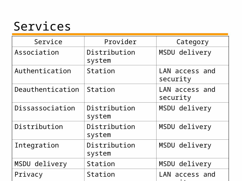
ServicesService Provider Category
Association Distribution system MSDU delivery
Authentication Station LAN access and security
Deauthentication Station LAN access and security
Dissassociation Distribution system MSDU delivery
Distribution Distribution system MSDU delivery
Integration Distribution system MSDU delivery
MSDU delivery Station MSDU delivery
Privacy Station LAN access and security
Reassocation Distribution system MSDU delivery

Medium Access Control• MAC layer covers three functional areas• Reliable data delivery• Access control• Security
—Beyond our scope

Reliable Data Delivery• 802.11 physical and MAC layers subject to unreliability• Noise, interference, and other propagation effects
result in loss of frames• Even with error-correction codes, frames may not
successfully be received• Can be dealt with at a higher layer, such as TCP
—However, retransmission timers at higher layers typically order of seconds
—More efficient to deal with errors at the MAC level
• 802.11 includes frame exchange protocol—Station receiving frame returns acknowledgment (ACK) frame—Exchange treated as atomic unit
• Not interrupted by any other station— If noACK within short period of time, retransmit

Four Frame Exchange• Basic data transfer involves exchange of two frames• To further enhance reliability, four-frame exchange
may be used—Source issues a Request to Send (RTS) frame to destination—Destination responds with Clear to Send (CTS)—After receiving CTS, source transmits data —Destination responds with ACK
• RTS alerts all stations within range of source that exchange is under way
• CTS alerts all stations within range of destination • Stations refrain from transmission to avoid collision• RTS/CTS exchange is required function of MAC but
may be disabled

Media Access Control• Distributed wireless foundation MAC
(DWFMAC)—Distributed access control mechanism—Optional centralized control on top
• Lower sublayer is distributed coordination function (DCF)—Contention algorithm to provide access to all traffic—Asynchronous traffic
• Point coordination function (PCF)—Centralized MAC algorithm—Contention free—Built on top of DCF

Figure 15.17 IEEE 802.11 Protocol Architecture

802.11 Physical Layer• Issued in four stages• First part in 1997
— IEEE 802.11 — Includes MAC layer and three physical layer
specifications—Two in 2.4-GHz band and one infrared—All operating at 1 and 2 Mbps
• Two additional parts in 1999— IEEE 802.11a
• 5-GHz band up to 54 Mbps— IEEE 802.11b
• 2.4-GHz band at 5.5 and 11 Mbps
• Most recent in 2002— IEEE 802.g extends IEEE 802.11b to higher data rates

IEEE 802.11 Physical Layer• Three physical media
—Direct-sequence spread spectrum—Frequency hopping spread spectrum—Infrared
• No market support
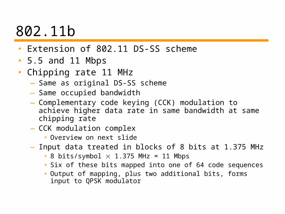
802.11b• Extension of 802.11 DS-SS scheme• 5.5 and 11 Mbps• Chipping rate 11 MHz
—Same as original DS-SS scheme—Same occupied bandwidth—Complementary code keying (CCK) modulation to
achieve higher data rate in same bandwidth at same chipping rate
—CCK modulation complex• Overview on next slide
— Input data treated in blocks of 8 bits at 1.375 MHz• 8 bits/symbol 1.375 MHz = 11 Mbps• Six of these bits mapped into one of 64 code sequences• Output of mapping, plus two additional bits, forms input to
QPSK modulator

802.11a• 5-GHz band• Uses orthogonal frequency division multiplexing (OFDM)
—Not spread spectrum
• Also called multicarrier modulation• Multiple carrier signals at different frequencies• Some bits on each channel
—Similar to FDM but all subchannels dedicated to single source
• Data rates 6, 9, 12, 18, 24, 36, 48, and 54 Mbps• Up to 52 subcarriers modulated using BPSK, QPSK, 16-
QAM, or 64-QAM—Depending on rate —Subcarrier frequency spacing 0.3125 MHz—Convolutional code at rate of 1/2, 2/3, or 3/4 provides forward
error correction

802.11g• Higher-speed extension to 802.11b• Combines physical layer encoding
techniques used in 802.11a and 802.11b to provide service at a variety of data rates

Required Reading• Stallings chapter 15• Web sites on Ethernet, Gbit Ethernet,
10Gbit Ethernet, 802.11 etc.


![Mainframes Refresher[2]](https://img.dokumen.tips/doc/110x75/577d20a81a28ab4e1e936e78/mainframes-refresher2.jpg)