Embed Size (px)
Citation preview

Local and Remote Techniques for Islanding Detection in Distributed Generators 119
Local and Remote Techniques for Islanding Detection in Distributed Generators
César Trujillo, David Velasco, Emilio Figueres and Gabriel Garcerá
X
Local and Remote Techniques for Islanding Detection in Distributed Generators
César Trujillo1, 2, David Velasco1, Emilio Figueres1 and Gabriel Garcerá1
1Universidad Politécnica de Valencia Spain
2Universidad Distrital Francisco José de Caldas Colombia
1. Introduction
The condition of "Islanding" in Distributed Generators (DG) is an electrical phenomenon that occurs when the energy supplied by the power grid is interrupted due to various factors and DG continues energizing some or the entire load. Thus, the power grid stops controlling this isolated part of the distribution system, which contains both loads and generators. Therefore it may compromise some relevant issues like security, restoration of service and reliability of the equipment (Pietzsch, 2004) (Report IEA T5-09-2002). Figure 1 shows a diagram of a DG connected to the power grid.
Fig. 1. Schematic configuration of the system In the case of several Distributed Generation Systems connected to a low-voltage power grid, it is possible that the amount of energy generated by the distributed system matches the amount of energy consumed by the loads. Under this situation, there is no energy flow with the power grid and the distributed systems may fail to detect a possible power grid disconnection, so that the DG system might continue feeding the loads, which would entail an “Islanding” condition. In addition, when the islanding condition happens, a primary security condition is that the generator system disconnects from the de-energized grid without taking into account the connected loads.
6
www.intechopen.com

Distributed Generation 120
Islanding may occur in inverters as a result of the following situations: 1. A failure detected by the grid, which results in a switch opening that is not
detected by the inverter or the protection devices. 2. Accidental opening of the electrical supply after a system failure. 3. Sudden changes in the network distribution system and/or in the loads. 4. Intentional disconnection for maintenance services either on the grid or in the
service entrance. 5. Human error or vandalism. 6. An act of nature.
There are many reasons why islanding should be anticipated in Distributed Generation systems connected to the grid. Some of the main reasons are safety, liability and maintenance of the quality of energy supplied to consumers. Consumers trust the quality of energy supplied by the grid, but they must also have anti-islanding inverters inside their distributed generation systems for the following reasons:
1. The grid can not control the voltage applied to the loads in islanding conditions, creating a possibility of user’s equipment may be damaged.
2. The power grid, along with the owner of the generating system, may be responsible for damage to connected equipment, resulting from variations in voltage and frequency outside the allowed limits.
3. Islanding can be a hazard to workers or grid users, because a line that is supposedly disconnected from any power source can remain active.
4. Uncontrolled reconnection in an isolated DG can damage the generation equipment or any other connected equipment, even block the line, because voltages in both the grid and the inverter can be out of phase.
5. Islanding may interfere with manual or automatic restoration of normal grid service.
Anti-islanding requirements have been evolving over many years and in different ways, depending on the countries laws. For instance, in the Netherlands they only require changes in flow frequency. Other countries like Germany or Austria require specific methods based on sudden impedance changes, known as ENS o MSD. Other countries have adopted standards that require inverters which can detect fails and shut down within set time limits. United States, for instance, requires inverters for grid connection that are certified for that purpose and it also requires that the certification tests of the inverters use a standard test circuit and a methodology based on “worst case” among countries considered as members of the International Energy Agency (IEA). This test was also chosen to allow a single inverter to be tested instead of testing multiple inverters. The main idea to detect Islanding is to supervise the DG output parameters and/or system parameters in order to determine if there have been changes which may point out whether it exists. Islanding detection techniques can be divided into remote and local techniques. Local techniques can be subdivided in passive and active, as shown by Figure 2 (Mahat et al., 2008).
Fig. 2. Classification of Islanding detection techniques Before defining the different methods of islanding detection, it is important to highlight two key features in order to understand the islanding phenomenon. The first one is associated with the so-called “Non-detection zone” (NDZ), which can be defined as the range (in terms of the difference between the power supplied by the DG inverter and that consumed by the load) in which an islanding detection scheme under test fails to detect this condition. The second one is associated with the nature of loads, which from a conservative point of view can be modelled as a parallel RLC circuit. The reason for using this model is primarily due to the difficulties that some detection techniques have to identify a islanding condition with such loads. Generally, non-linear loads, such loads that produce harmonics or constant power loads do not present difficulties in islanding detection. (Report IEA-T5-09, 2002). In particular, RLC loads with high Q factor have problems with island detection. Quality Factor is defined as:
CLRQ
(1)
This parameter describes the relationship between stored and dissipated energy in the RLC circuit. Loads with a high Q have large capacitance and small inductances and/or big parallel resistances. Once they are defined both NDZ and the more critical loads connected to a DG inverter for islanding phenomenon detection, the most outstanding detection techniques will be described.
2. Local islanding detection techniques
These techniques are based on the measure of some parameters (voltage, current, frequency, among others) on the Distributed Generator side. They are classified as passive, based solely on the monitoring of these parameters; and active techniques, which intentionally introduce disturbances at the output of the inverter and observe whether the parameters outlined above are affected.
www.intechopen.com
Local and Remote Techniques for Islanding Detection in Distributed Generators 121
Islanding may occur in inverters as a result of the following situations: 1. A failure detected by the grid, which results in a switch opening that is not
detected by the inverter or the protection devices. 2. Accidental opening of the electrical supply after a system failure. 3. Sudden changes in the network distribution system and/or in the loads. 4. Intentional disconnection for maintenance services either on the grid or in the
service entrance. 5. Human error or vandalism. 6. An act of nature.
There are many reasons why islanding should be anticipated in Distributed Generation systems connected to the grid. Some of the main reasons are safety, liability and maintenance of the quality of energy supplied to consumers. Consumers trust the quality of energy supplied by the grid, but they must also have anti-islanding inverters inside their distributed generation systems for the following reasons:
1. The grid can not control the voltage applied to the loads in islanding conditions, creating a possibility of user’s equipment may be damaged.
2. The power grid, along with the owner of the generating system, may be responsible for damage to connected equipment, resulting from variations in voltage and frequency outside the allowed limits.
3. Islanding can be a hazard to workers or grid users, because a line that is supposedly disconnected from any power source can remain active.
4. Uncontrolled reconnection in an isolated DG can damage the generation equipment or any other connected equipment, even block the line, because voltages in both the grid and the inverter can be out of phase.
5. Islanding may interfere with manual or automatic restoration of normal grid service.
Anti-islanding requirements have been evolving over many years and in different ways, depending on the countries laws. For instance, in the Netherlands they only require changes in flow frequency. Other countries like Germany or Austria require specific methods based on sudden impedance changes, known as ENS o MSD. Other countries have adopted standards that require inverters which can detect fails and shut down within set time limits. United States, for instance, requires inverters for grid connection that are certified for that purpose and it also requires that the certification tests of the inverters use a standard test circuit and a methodology based on “worst case” among countries considered as members of the International Energy Agency (IEA). This test was also chosen to allow a single inverter to be tested instead of testing multiple inverters. The main idea to detect Islanding is to supervise the DG output parameters and/or system parameters in order to determine if there have been changes which may point out whether it exists. Islanding detection techniques can be divided into remote and local techniques. Local techniques can be subdivided in passive and active, as shown by Figure 2 (Mahat et al., 2008).
Fig. 2. Classification of Islanding detection techniques Before defining the different methods of islanding detection, it is important to highlight two key features in order to understand the islanding phenomenon. The first one is associated with the so-called “Non-detection zone” (NDZ), which can be defined as the range (in terms of the difference between the power supplied by the DG inverter and that consumed by the load) in which an islanding detection scheme under test fails to detect this condition. The second one is associated with the nature of loads, which from a conservative point of view can be modelled as a parallel RLC circuit. The reason for using this model is primarily due to the difficulties that some detection techniques have to identify a islanding condition with such loads. Generally, non-linear loads, such loads that produce harmonics or constant power loads do not present difficulties in islanding detection. (Report IEA-T5-09, 2002). In particular, RLC loads with high Q factor have problems with island detection. Quality Factor is defined as:
CLRQ
(1)
This parameter describes the relationship between stored and dissipated energy in the RLC circuit. Loads with a high Q have large capacitance and small inductances and/or big parallel resistances. Once they are defined both NDZ and the more critical loads connected to a DG inverter for islanding phenomenon detection, the most outstanding detection techniques will be described.
2. Local islanding detection techniques
These techniques are based on the measure of some parameters (voltage, current, frequency, among others) on the Distributed Generator side. They are classified as passive, based solely on the monitoring of these parameters; and active techniques, which intentionally introduce disturbances at the output of the inverter and observe whether the parameters outlined above are affected.
www.intechopen.com
Distributed Generation 122
2.1 Passive techniques of islanding detection These techniques are based on islanding detection through monitoring of parameters such as voltage, current, frequency and/or their characteristics. They interrupt the inverter energy conversion when there are changes beyond some limits previously established.
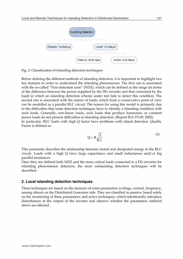
2.1.1 Over/under-voltage and over/under-frequency passive techniques of islanding detection Before going into the method description, an analysis related to the power balance of the system will be done in order to identify how monitored parameters can be affected when the energy flow is interrupted by the grid. Figure 3 shows the power balance of the system.
Fig. 3. Power balance in a local load supplied both by the grid and a distributed generator Equations (2) and (3) describe the power balance of the system.
PDGPLOADP (2)
QDGQLOADQ (3) If PLOAD = PDG and/or if QLOAD = QDG, there is not active or reactive power mismatch between the DG and the power grid. The behaviour of the system when the grid is disconnected depends on the previous values of ΔP y ΔQ (Liserre et al., 2006). It is worth to point out that the active power is directly proportional to the voltage. Therefore, if ΔP ≠ 0, the amplitude of the voltage will change. At first, when there is a disconnection of the grid, the power consumed by the load is forced to be the same as the one generated by the DG, so that the voltage value in the grid changes to:
VLOADP
DGPV '
(4)
In the case of PDG >PLOAD, the voltage increases, otherwise it decreases, which might indicate whether the islanding conditions appears. Reactive power is a function of frequency and voltage width, so if ΔQ ≠ 0, the phase of the load voltage will present a sudden change and the control system will modify the signal frequency of the output current inverter to achieve ΔQ = 0 (i.e. until it reaches the resonance frequency of the load). This change in the frequency may be detected to determine Islanding
condition. The equation of reactive power in terms of frequency and voltage is presented by (5).
'''
' VCLDGQ
LOADQ
1 (5)
Techniques of over/under voltage protection, OVP/UVP and over/under frequency protection, OFP/UFP, (Report IEA-T5-09, 2002), (Mahat et al., 2008) allow the detection of islanding phenomenon through the measure of voltage and/or frequency at the Point of Common Coupling (PCC), and subsequent comparison with the limits set for proper operation (IEEE 929, 2000). If the measured values are outside the established range, the inverter is stopped or disconnected. This method is not only a mechanism to detect islanding, it also protects the inverter. Figure 4 shows the mapping of the NDZ in the plane ΔP versus ΔQ for OUV and OUF.
Fig. 4. Non-detection zone of OUV and OUF techniques The methods outlined above present the advantage of being low-cost solutions but they have a large NDZ. Moreover, these methods are incapable of detecting the islanding condition when the power supplied by the DG matches the power consumed by the loads.
2.1.2 Phase Jump Detection Phase Jump Detection technique (PJD), (Report IEA-T5-09, 2002), (Kobayashi et al., 1991) involves monitoring of sudden “jumps” of the inverter voltage as a consequence of differences between the voltage inverter and its output current. During normal operation the current of the inverter is synchronized with the voltage of the power grid through a Phase Locked Loop (PLL). Figure 5 shows the evolution of the voltage when it is disconnected from the power grid. This phenomenon occurs because only the output current is controlled by the inverter, so that the PCC voltage may be out of phase with regard the current in the case of islanding.
www.intechopen.com

Local and Remote Techniques for Islanding Detection in Distributed Generators 123
2.1 Passive techniques of islanding detection These techniques are based on islanding detection through monitoring of parameters such as voltage, current, frequency and/or their characteristics. They interrupt the inverter energy conversion when there are changes beyond some limits previously established.
2.1.1 Over/under-voltage and over/under-frequency passive techniques of islanding detection Before going into the method description, an analysis related to the power balance of the system will be done in order to identify how monitored parameters can be affected when the energy flow is interrupted by the grid. Figure 3 shows the power balance of the system.
Fig. 3. Power balance in a local load supplied both by the grid and a distributed generator Equations (2) and (3) describe the power balance of the system.
PDGPLOADP (2)
QDGQLOADQ (3) If PLOAD = PDG and/or if QLOAD = QDG, there is not active or reactive power mismatch between the DG and the power grid. The behaviour of the system when the grid is disconnected depends on the previous values of ΔP y ΔQ (Liserre et al., 2006). It is worth to point out that the active power is directly proportional to the voltage. Therefore, if ΔP ≠ 0, the amplitude of the voltage will change. At first, when there is a disconnection of the grid, the power consumed by the load is forced to be the same as the one generated by the DG, so that the voltage value in the grid changes to:
VLOADP
DGPV '
(4)
In the case of PDG >PLOAD, the voltage increases, otherwise it decreases, which might indicate whether the islanding conditions appears. Reactive power is a function of frequency and voltage width, so if ΔQ ≠ 0, the phase of the load voltage will present a sudden change and the control system will modify the signal frequency of the output current inverter to achieve ΔQ = 0 (i.e. until it reaches the resonance frequency of the load). This change in the frequency may be detected to determine Islanding
condition. The equation of reactive power in terms of frequency and voltage is presented by (5).
'''
' VCLDGQ
LOADQ
1 (5)
Techniques of over/under voltage protection, OVP/UVP and over/under frequency protection, OFP/UFP, (Report IEA-T5-09, 2002), (Mahat et al., 2008) allow the detection of islanding phenomenon through the measure of voltage and/or frequency at the Point of Common Coupling (PCC), and subsequent comparison with the limits set for proper operation (IEEE 929, 2000). If the measured values are outside the established range, the inverter is stopped or disconnected. This method is not only a mechanism to detect islanding, it also protects the inverter. Figure 4 shows the mapping of the NDZ in the plane ΔP versus ΔQ for OUV and OUF.
Fig. 4. Non-detection zone of OUV and OUF techniques The methods outlined above present the advantage of being low-cost solutions but they have a large NDZ. Moreover, these methods are incapable of detecting the islanding condition when the power supplied by the DG matches the power consumed by the loads.
2.1.2 Phase Jump Detection Phase Jump Detection technique (PJD), (Report IEA-T5-09, 2002), (Kobayashi et al., 1991) involves monitoring of sudden “jumps” of the inverter voltage as a consequence of differences between the voltage inverter and its output current. During normal operation the current of the inverter is synchronized with the voltage of the power grid through a Phase Locked Loop (PLL). Figure 5 shows the evolution of the voltage when it is disconnected from the power grid. This phenomenon occurs because only the output current is controlled by the inverter, so that the PCC voltage may be out of phase with regard the current in the case of islanding.
www.intechopen.com

Distributed Generation 124
Fig. 5. Operation of PJD The biggest advantage presented by PJD is its ease of implementation. As the inverter uses a PLL to synchronize with the grid, all that it is needed is the inverter capacity to be disconnected if the phase error between output current and voltage exceeds certain threshold. However, difficulty comes in the implementation of the threshold selection because the phase can be affected by the handling of certain loads such as motors or simply by being on presence of loads that can not produce phase error, which could induce an error in the detection of islanding.
2.1.3 Detection of voltage and current harmonics This technique is based on the measurement of the voltage Total Harmonic Distortion (THDv) at the PCC, the comparison of the measured value with a certain threshold and the inverter disconnection in case of this threshold is exceed (Report IEA-T5-09, 2002), (De Mango et al., 2006), (Jang & Kim, 2004). During normal operation, the voltage at the PCC is the grid voltage, so distortion can be considered as negligible (THDv≈0) in most cases. However, when islanding condition happens, the current harmonics produced by the inverter are transmitted to the load, which usually presents higher impedance than the grid. The interaction of the harmonic currents and the grid impedance generates voltage harmonics which can be measured. Therefore, the THDv variations beyond a certain threshold can be used to detect islanding. This method has the advantage that its effectiveness does not change where there are multiple inverters. However, it is sensitive to grid perturbations, which makes the threshold establishment more difficult for islanding detection. For instance, with non-linear loads, the voltage distortion at the PCC can be so high that a fault may be erroneously detected even if the grid is present. Additionally, with linear loads the THDv variation may be too low to be detected.
2.1.4 Detection based on state estimators (Liserre et al., 2006) The basic idea of this technique is based on applying a voltage oriented control combined with the use of resonant controllers. As it is shown by Fig. 6, an algorithm based on Kalman
filters is used to estimate the third and the fifth harmonic of the grid voltages. The correspondence between the energy of both the estimated values and the measured ones can be used to identify islanding condition.
Sensorless controller PWM
Inverter
Load
GridPCC
Utility breaker
Primary Source
Kalman filter
Energy measurement
Islanding detection
P
Q
W
Stop
-+
E
Ê1i
Fig. 6. Scheme of the islanding detection algorithm based on state estimators Detection based on state estimators has the advantage of being a passive method which does not affect the system power quality. It presents a very low NDZ and an islanding detection rate very high, comfortably in line with IEEE. However, it demands more complexity from the programming point of view compared with other passive techniques of islanding detection.
2.2 Active techniques for islanding detection These techniques intentionally introduce disturbances at the output of the inverter to determine if they affect voltage, frequency and impedance parameters, in which case it is assumed that the grid has been disconnected and the inverter is isolated from the load. Active techniques have the advantage of remarkably reducing or even eliminating the NDZ. However, they may deteriorate the quality of the grid voltages or even they may cause instability.
2.2.1 Impedance measurement Techniques based on impedance measurement seek to detect impedance changes at the output of the inverter, which is produced when the electric distribution grid, which is supposed to have low impedance, disconnects from the system. (Report IEA-T5-09, 2002), (Ropp et al., 2006), (Ciobotaru, 2007). The inverter of the DG behaves as a current source which injects a current as follows: DGtDGinvDGIinvDGi sin (6) Usually, a disturbance is added to the inverter output current, IDG-inv, which causes the output voltage to suffer from changes when the grid is disconnected. This variation is monitored by calculating the dv/di, which represents the grid impedance that it is ‘seen’ by the inverter.
www.intechopen.com

Local and Remote Techniques for Islanding Detection in Distributed Generators 125
Fig. 5. Operation of PJD The biggest advantage presented by PJD is its ease of implementation. As the inverter uses a PLL to synchronize with the grid, all that it is needed is the inverter capacity to be disconnected if the phase error between output current and voltage exceeds certain threshold. However, difficulty comes in the implementation of the threshold selection because the phase can be affected by the handling of certain loads such as motors or simply by being on presence of loads that can not produce phase error, which could induce an error in the detection of islanding.
2.1.3 Detection of voltage and current harmonics This technique is based on the measurement of the voltage Total Harmonic Distortion (THDv) at the PCC, the comparison of the measured value with a certain threshold and the inverter disconnection in case of this threshold is exceed (Report IEA-T5-09, 2002), (De Mango et al., 2006), (Jang & Kim, 2004). During normal operation, the voltage at the PCC is the grid voltage, so distortion can be considered as negligible (THDv≈0) in most cases. However, when islanding condition happens, the current harmonics produced by the inverter are transmitted to the load, which usually presents higher impedance than the grid. The interaction of the harmonic currents and the grid impedance generates voltage harmonics which can be measured. Therefore, the THDv variations beyond a certain threshold can be used to detect islanding. This method has the advantage that its effectiveness does not change where there are multiple inverters. However, it is sensitive to grid perturbations, which makes the threshold establishment more difficult for islanding detection. For instance, with non-linear loads, the voltage distortion at the PCC can be so high that a fault may be erroneously detected even if the grid is present. Additionally, with linear loads the THDv variation may be too low to be detected.
2.1.4 Detection based on state estimators (Liserre et al., 2006) The basic idea of this technique is based on applying a voltage oriented control combined with the use of resonant controllers. As it is shown by Fig. 6, an algorithm based on Kalman
filters is used to estimate the third and the fifth harmonic of the grid voltages. The correspondence between the energy of both the estimated values and the measured ones can be used to identify islanding condition.
Sensorless controller PWM
Inverter
Load
GridPCC
Utility breaker
Primary Source
Kalman filter
Energy measurement
Islanding detection
P
Q
W
Stop
-+
E
Ê1i
Fig. 6. Scheme of the islanding detection algorithm based on state estimators Detection based on state estimators has the advantage of being a passive method which does not affect the system power quality. It presents a very low NDZ and an islanding detection rate very high, comfortably in line with IEEE. However, it demands more complexity from the programming point of view compared with other passive techniques of islanding detection.
2.2 Active techniques for islanding detection These techniques intentionally introduce disturbances at the output of the inverter to determine if they affect voltage, frequency and impedance parameters, in which case it is assumed that the grid has been disconnected and the inverter is isolated from the load. Active techniques have the advantage of remarkably reducing or even eliminating the NDZ. However, they may deteriorate the quality of the grid voltages or even they may cause instability.
2.2.1 Impedance measurement Techniques based on impedance measurement seek to detect impedance changes at the output of the inverter, which is produced when the electric distribution grid, which is supposed to have low impedance, disconnects from the system. (Report IEA-T5-09, 2002), (Ropp et al., 2006), (Ciobotaru, 2007). The inverter of the DG behaves as a current source which injects a current as follows: DGtDGinvDGIinvDGi sin (6) Usually, a disturbance is added to the inverter output current, IDG-inv, which causes the output voltage to suffer from changes when the grid is disconnected. This variation is monitored by calculating the dv/di, which represents the grid impedance that it is ‘seen’ by the inverter.
www.intechopen.com

Distributed Generation 126
The main advantage of the impedance measurement method is its small NDZ. However, this method has many weaknesses. The first one is that its effectiveness decreases as the number of inverters connected to the grid increases unless all the inverters use this method and they all are synchronized. The second one is that it is necessary to establish an impedance threshold to identify when the grid is connected. This requires the exact value of the grid impedance which is a parameter initially unknown. It makes this method sometimes impractical.
2.2.2 Harmonic injection/detection of impedance This method involves intentionally injecting a specific current harmonic at the PCC. (Chunjiang et al., 2006), (Ciobotaru et al., 2008). When the grid is connected, if the grid impedance is lower than the load impedance at the harmonic frequency, then the injected harmonic current will flow into the grid. The size of the disturbance that appears at the voltage amplitude will depend on the nominal values of the grid impedance. After the grid disconnection, the harmonic current will flow through the load, producing a specific harmonic voltage. The name of this method comes from the fact that the amplitude of the generated voltage harmonics will be proportional to the impedance of the load at the frequency of the injected harmonic current. Figure 7 shows a diagram of this method.
Fig. 7. Structure of islanding detection method based on harmonic injection This method presents the same advantages and disadvantages of the harmonic detection technique. However, the disadvantages can be overcome if subharmonic signals are injected instead of high order harmonics. Unfortunately, problems are not definitively solved unless the amplitude of the injected harmonics is very small.
2.2.3 Sliding Mode Frequency Shift (SMS) The operation principle of the SMS method is based on varying the inverter output frequency by controlling the phase of the inverter current (Sun et al., 2004), (Lopes & Sun, 2006). Usually, DG operates with unity power factor, so in normal operation the inverter output current-voltage phase angle of the inverter, instead to be controlled to be zero, is made to be a function of the frequency of the PCC voltage, as shown in Figure 8.
Fig. 8. Voltage-current phase Angle vs. Frequency controlled by SMS The phase response curve of the inverter is designed such that the phase of the inverter increases faster than the phase of the (RLC) load with a unity-power factor in the region near the grid frequency. This makes the line frequency an unstable operating point for the inverter. While the grid is connected, it stabilizes the operating point at the line frequency by providing a solid phase and frequency reference. However, after the island is formed, the phase-frequency operating point of the load and inverter must be at an intersection of the load line and inverter phase response curve. This method is relatively easy to implement because it is just a slight modification of a component which is already required, the PLL. Additionally, it has a small NDZ compared with other methods. It also has the advantage of being effective when dealing with multiple inverters and it offers a good compromise between islanding detection, the output power quality and transitory response. However, SMS method requires a decrease in the power quality of the DG inverter.
2.2.4 Active Frequency Drift (AFD) The basis of AFD method is to vary the frequency of the output current by means of a positive feedback (Report IEA-T5-09, 2002), (Sun et al., 2004), (Lopes & Sun, 2006). The method is based on the injection of a current into the PCC slightly distorted in frequency as shown in Figure 9. When a grid disconnection occurs, a phase error appears between the inverter current and the voltage at the PCC. The inverter detects this error and tries to compensate it by increasing the frequency of the generated current. This process continues until the frequency exceeds the limits and is detected by the OFP / UFP.
www.intechopen.com

Local and Remote Techniques for Islanding Detection in Distributed Generators 127
The main advantage of the impedance measurement method is its small NDZ. However, this method has many weaknesses. The first one is that its effectiveness decreases as the number of inverters connected to the grid increases unless all the inverters use this method and they all are synchronized. The second one is that it is necessary to establish an impedance threshold to identify when the grid is connected. This requires the exact value of the grid impedance which is a parameter initially unknown. It makes this method sometimes impractical.
2.2.2 Harmonic injection/detection of impedance This method involves intentionally injecting a specific current harmonic at the PCC. (Chunjiang et al., 2006), (Ciobotaru et al., 2008). When the grid is connected, if the grid impedance is lower than the load impedance at the harmonic frequency, then the injected harmonic current will flow into the grid. The size of the disturbance that appears at the voltage amplitude will depend on the nominal values of the grid impedance. After the grid disconnection, the harmonic current will flow through the load, producing a specific harmonic voltage. The name of this method comes from the fact that the amplitude of the generated voltage harmonics will be proportional to the impedance of the load at the frequency of the injected harmonic current. Figure 7 shows a diagram of this method.
Fig. 7. Structure of islanding detection method based on harmonic injection This method presents the same advantages and disadvantages of the harmonic detection technique. However, the disadvantages can be overcome if subharmonic signals are injected instead of high order harmonics. Unfortunately, problems are not definitively solved unless the amplitude of the injected harmonics is very small.
2.2.3 Sliding Mode Frequency Shift (SMS) The operation principle of the SMS method is based on varying the inverter output frequency by controlling the phase of the inverter current (Sun et al., 2004), (Lopes & Sun, 2006). Usually, DG operates with unity power factor, so in normal operation the inverter output current-voltage phase angle of the inverter, instead to be controlled to be zero, is made to be a function of the frequency of the PCC voltage, as shown in Figure 8.
Fig. 8. Voltage-current phase Angle vs. Frequency controlled by SMS The phase response curve of the inverter is designed such that the phase of the inverter increases faster than the phase of the (RLC) load with a unity-power factor in the region near the grid frequency. This makes the line frequency an unstable operating point for the inverter. While the grid is connected, it stabilizes the operating point at the line frequency by providing a solid phase and frequency reference. However, after the island is formed, the phase-frequency operating point of the load and inverter must be at an intersection of the load line and inverter phase response curve. This method is relatively easy to implement because it is just a slight modification of a component which is already required, the PLL. Additionally, it has a small NDZ compared with other methods. It also has the advantage of being effective when dealing with multiple inverters and it offers a good compromise between islanding detection, the output power quality and transitory response. However, SMS method requires a decrease in the power quality of the DG inverter.
2.2.4 Active Frequency Drift (AFD) The basis of AFD method is to vary the frequency of the output current by means of a positive feedback (Report IEA-T5-09, 2002), (Sun et al., 2004), (Lopes & Sun, 2006). The method is based on the injection of a current into the PCC slightly distorted in frequency as shown in Figure 9. When a grid disconnection occurs, a phase error appears between the inverter current and the voltage at the PCC. The inverter detects this error and tries to compensate it by increasing the frequency of the generated current. This process continues until the frequency exceeds the limits and is detected by the OFP / UFP.
www.intechopen.com

Distributed Generation 128
tZ
t(s)
Iout(A)
2VutilT
2IpvT
Distorted current waveform
Pure sinusoidal waveform
Fig. 9. Inverter current waveform distorted by using AFD The relationship between tZ in Figure 9 and half of the voltage period is called the chopping factor:
VutilTZtcf
2
(7)
This method can be easily implemented and applied to multiple inverters. However, the AFD method produces a small degradation in the quality of the DG output and the inverter has an NDZ that depends on the value of the chopping factor. There are similar techniques allowing to obtain better results by changing the chopping factor, with a significant reduction in the NDZ, like the following ones: Active Frequency Drift with Positive Feedback (AFDPF) (Jung et al., 2005), AFD with Pulsation of Chopping Fraction (AFDPCF) (Liu et al., 2007), among others.
2.2.5 Frequency jump The Frequency Jump (FJ) method is a modification of AFD, and it is conceptually similar to the impedance estimation techniques. In the FJ method, dead zones are inserted into some cycles of the output current waveform. Instead, the frequency is “dithered” according to a pre-assigned pattern (Report IEA-T5-09, 2002), (Nehrir & Menon, 2007). When the inverter is connected to the utility, the waveform of the voltage in the PCC is imposed by the grid. However, when the grid is disconnected, the Islanding situation is detected by forcing a deviation in frequency. The main advantage of this method is that if the pattern is sufficiently sophisticated, FJ may be relatively effective in Islanding detection when used with a single inverter. Furthermore, this method hardly presents NDZ in single-inverter case and it loses effectiveness when connecting multiple inverters, unless the frequencies dithering between inverters are synchronized.
2.2.6 Variation of active power and reactive power This method is based on the ability of the inverter to generate independently both active and reactive power (Jeraputra & Enjeti., 2004), (Mango et al., 2006), (Ye et al., 2004), (Jeong et al., 2005). In islanding, the voltage variation with regard to the active power injected by the inverter may be obtained from the power flow shown by Figure 3. The power supplied by the inverter can be expressed as:
RVPP LOADDG
2 (8)
Differentiating PDG with regard to voltage and expressing it in terms of power it results:
RP
RV
VP DGDG
22 (9)
Hence voltage variation in terms of power can be expressed as:
DG
DG
PRP
V 2
(10)
Since both R and PDG are constant, voltage variation is directly proportional to the variation of active power. Hence, it is possible to vary the active power injected by the inverter in order to bring the amplitude of the voltage outside the normal operating range and be able to detect islanding. It is necessary to choose carefully when the power is injected because continuous variations of the injected power can perturb the Maximum Power Point Tracking (MPPT) algorithms. For these reasons, this method involves the injection of active power only when the voltage measured at the PCC exceeds a certain threshold value (Vs). The time needed by the algorithm to detect a fault can be adjusted with a Kv that increases o decreases dP proportionally to the voltage variation. This value should be chosen large enough to detect the islanding situation avoiding overcurrents which may damage the system elements. An initial value of the constant can be obtained from equation (10). The current reference for the inverter control can be calculated as follows:
VPdPI DG
ref (11)
Where dP=Kv(V-Vn), Vn being the amplitude of the nominal voltage and V the measurement of the feedback voltage amplitude. Similarly to the relationship between voltage and active power, a strong dependence between frequency and reactive power exists, which may be used to develop another method of islanding, based on measuring the grid frequency (Sanchis et al., 2005). Since Std. 929-2000 recommends DG operation near to a unity power factor, the generated reactive power must be zero in normal operation. At the beginning of islanding, equation (12) remains valid, so that the frequency depends on the values of the inductive and capacitive
www.intechopen.com

Local and Remote Techniques for Islanding Detection in Distributed Generators 129
tZ
t(s)
Iout(A)
2VutilT
2IpvT
Distorted current waveform
Pure sinusoidal waveform
Fig. 9. Inverter current waveform distorted by using AFD The relationship between tZ in Figure 9 and half of the voltage period is called the chopping factor:
VutilTZtcf
2
(7)
This method can be easily implemented and applied to multiple inverters. However, the AFD method produces a small degradation in the quality of the DG output and the inverter has an NDZ that depends on the value of the chopping factor. There are similar techniques allowing to obtain better results by changing the chopping factor, with a significant reduction in the NDZ, like the following ones: Active Frequency Drift with Positive Feedback (AFDPF) (Jung et al., 2005), AFD with Pulsation of Chopping Fraction (AFDPCF) (Liu et al., 2007), among others.
2.2.5 Frequency jump The Frequency Jump (FJ) method is a modification of AFD, and it is conceptually similar to the impedance estimation techniques. In the FJ method, dead zones are inserted into some cycles of the output current waveform. Instead, the frequency is “dithered” according to a pre-assigned pattern (Report IEA-T5-09, 2002), (Nehrir & Menon, 2007). When the inverter is connected to the utility, the waveform of the voltage in the PCC is imposed by the grid. However, when the grid is disconnected, the Islanding situation is detected by forcing a deviation in frequency. The main advantage of this method is that if the pattern is sufficiently sophisticated, FJ may be relatively effective in Islanding detection when used with a single inverter. Furthermore, this method hardly presents NDZ in single-inverter case and it loses effectiveness when connecting multiple inverters, unless the frequencies dithering between inverters are synchronized.
2.2.6 Variation of active power and reactive power This method is based on the ability of the inverter to generate independently both active and reactive power (Jeraputra & Enjeti., 2004), (Mango et al., 2006), (Ye et al., 2004), (Jeong et al., 2005). In islanding, the voltage variation with regard to the active power injected by the inverter may be obtained from the power flow shown by Figure 3. The power supplied by the inverter can be expressed as:
RVPP LOADDG
2 (8)
Differentiating PDG with regard to voltage and expressing it in terms of power it results:
RP
RV
VP DGDG
22 (9)
Hence voltage variation in terms of power can be expressed as:
DG
DG
PRP
V 2
(10)
Since both R and PDG are constant, voltage variation is directly proportional to the variation of active power. Hence, it is possible to vary the active power injected by the inverter in order to bring the amplitude of the voltage outside the normal operating range and be able to detect islanding. It is necessary to choose carefully when the power is injected because continuous variations of the injected power can perturb the Maximum Power Point Tracking (MPPT) algorithms. For these reasons, this method involves the injection of active power only when the voltage measured at the PCC exceeds a certain threshold value (Vs). The time needed by the algorithm to detect a fault can be adjusted with a Kv that increases o decreases dP proportionally to the voltage variation. This value should be chosen large enough to detect the islanding situation avoiding overcurrents which may damage the system elements. An initial value of the constant can be obtained from equation (10). The current reference for the inverter control can be calculated as follows:
VPdPI DG
ref (11)
Where dP=Kv(V-Vn), Vn being the amplitude of the nominal voltage and V the measurement of the feedback voltage amplitude. Similarly to the relationship between voltage and active power, a strong dependence between frequency and reactive power exists, which may be used to develop another method of islanding, based on measuring the grid frequency (Sanchis et al., 2005). Since Std. 929-2000 recommends DG operation near to a unity power factor, the generated reactive power must be zero in normal operation. At the beginning of islanding, equation (12) remains valid, so that the frequency depends on the values of the inductive and capacitive
www.intechopen.com

Distributed Generation 130
components of the load. Therefore, the variation of Q with ω follows (13), where ω0 is the resonance frequency of the equivalent RLC circuit (14).
CL
VQQ LOADDG 10 2
(12)
oddQQ
o
0 (13)
LCo1
(14)
Solving equation (13), in order to determine the variation of the frequency as a function of Q and setting the frequency of the load at the resonance frequency, it is obtained:
QLC
LVo
o
12
22
(15)
As observed in (15), the frequency variation is directly proportional to the changes of reactive power and it can be obtained the expression of ∆f as a function of the quality factor Qf , the resonance frequency fo and the active power PDG, following (16).
QQP
ff
fDG
o
2
(16)
The reference frequency for the inverter control can be calculated as follows: gfgref ffKff (17) Where fg is the grid frequency, f is the measured frequency and Kf is a constant that allows to accelerate the islanding detection. Kf may be calculated taking into account the parameters of equation (16). Figure 10 shows the diagram of the method.
Primary Source
InverterDC/AC
PLL
Grid
Va
Phase
Frequency
Kf <
Control
-+fn
Amplitude
-+ Vn
LPF
++
Qdg
dQ
Kv <++
Pdg
dP
Ia
-+ Gi(s)
Control
Current control
QP
Fig. 10. Block diagram on P and Q injection method The disadvantage of this method is that it can generate false detections of islanding when several inverters are connected to the same point of the grid. Moreover, instability problems may appear because the inverter is continuously injecting disturbances into the grid.
2.2.7 Sandia Frequency Shift (SFS) This is an accelerated version of AFD and it is one of the positive feedback methods used to prevent the islanding operation (Report IEA-T5-09, 2002), (Lopes & Sun, 2006), (Wang et al. 2007) (John et al., 2004). With the grid connected, the method detects and tries to amplify small changes in frequency, but the presence of the grid avoid it. When the grid is disconnected, the frequency changes produce phase error and the positive feedback, in an iterative process, come the frequency beyond the threshold of OFP or UFP. When the method is implemented, it is calculated the reference frequency for the inverter as a function of both the value at the iteration n and its variation ∆f, following (18).
1 ·n n ff f K f (18)
Where fn+1 is the reference frequency for the inverter in the n+1 cycle, fn is the frequency in the n cycle and Kf is a constant that allows to accelerate the islanding detection. Finally ∆fn is the frequency variation in each cycle. Kf is designed to compensate the natural tendency of the system to move to the load resonance frequency when such a resonance frequency falls within the thresholds established to detect islanding. In the n+1 cycle the inverter injects a current with a certain frequency. Therefore, the load introduces a sliding phase angle φ corresponding to an interval of time Tps following (19).
www.intechopen.com

Local and Remote Techniques for Islanding Detection in Distributed Generators 131
components of the load. Therefore, the variation of Q with ω follows (13), where ω0 is the resonance frequency of the equivalent RLC circuit (14).
CL
VQQ LOADDG 10 2
(12)
oddQQ
o
0 (13)
LCo1
(14)
Solving equation (13), in order to determine the variation of the frequency as a function of Q and setting the frequency of the load at the resonance frequency, it is obtained:
QLC
LVo
o
12
22
(15)
As observed in (15), the frequency variation is directly proportional to the changes of reactive power and it can be obtained the expression of ∆f as a function of the quality factor Qf , the resonance frequency fo and the active power PDG, following (16).
QQP
ff
fDG
o
2
(16)
The reference frequency for the inverter control can be calculated as follows: gfgref ffKff (17) Where fg is the grid frequency, f is the measured frequency and Kf is a constant that allows to accelerate the islanding detection. Kf may be calculated taking into account the parameters of equation (16). Figure 10 shows the diagram of the method.
Primary Source
InverterDC/AC
PLL
Grid
Va
Phase
Frequency
Kf <
Control
-+fn
Amplitude
-+ Vn
LPF
++
Qdg
dQ
Kv <++
Pdg
dP
Ia
-+ Gi(s)
Control
Current control
QP
Fig. 10. Block diagram on P and Q injection method The disadvantage of this method is that it can generate false detections of islanding when several inverters are connected to the same point of the grid. Moreover, instability problems may appear because the inverter is continuously injecting disturbances into the grid.
2.2.7 Sandia Frequency Shift (SFS) This is an accelerated version of AFD and it is one of the positive feedback methods used to prevent the islanding operation (Report IEA-T5-09, 2002), (Lopes & Sun, 2006), (Wang et al. 2007) (John et al., 2004). With the grid connected, the method detects and tries to amplify small changes in frequency, but the presence of the grid avoid it. When the grid is disconnected, the frequency changes produce phase error and the positive feedback, in an iterative process, come the frequency beyond the threshold of OFP or UFP. When the method is implemented, it is calculated the reference frequency for the inverter as a function of both the value at the iteration n and its variation ∆f, following (18).
1 ·n n ff f K f (18)
Where fn+1 is the reference frequency for the inverter in the n+1 cycle, fn is the frequency in the n cycle and Kf is a constant that allows to accelerate the islanding detection. Finally ∆fn is the frequency variation in each cycle. Kf is designed to compensate the natural tendency of the system to move to the load resonance frequency when such a resonance frequency falls within the thresholds established to detect islanding. In the n+1 cycle the inverter injects a current with a certain frequency. Therefore, the load introduces a sliding phase angle φ corresponding to an interval of time Tps following (19).
www.intechopen.com

Distributed Generation 132
112· 2· ·ps n
n
T Tf
(19)
Kf is chosen to maintain the sliding frequency below the resonance frequency. In principle, this condition implies that the frequency in the n+1 cycle must be higher (for an increasing change) than the one of the n cycle, which yields in the following condition:
n
nf
nnfnnfnn f
fKffKffKf
f
21
21
11
1 (20)
Another issue for choosing the value of Kf is the desired time response. This can be accomplished by imposing a minimum time variation called shift time Tf. Therefore, it is obtained:
11
11
21
fnnfnnfn
n TffKffKf
f (21)
For frequencies close to the grid frequency the term 2πfnTf is appreciably greater that the phase-shift angle φ and the term (1- fnTf) approaches 1. With these simplifications it is obtained (22):
n
fnf
nfn
fnnf f
TfK
fTfTf
fK
2
212
(22)
Figure 11 shows the block diagram of the method.
Fig. 11. Block diagram of the SFS method
2.2.8 Sandia Voltage Shift (SVS) This method uses a positive feedback loop of the PCC voltage amplitude and it is similar to the active power variation technique. If the voltage amplitude (usually measured in RMS value) decreases, the inverter reduces its output current and thus the output power (Report IEA-T5-09, 2002), (John et al., 2004). The active power variation can be expressed following (23).
RVVPDG 2 (23)
∆V can be calculated by comparing the voltage value with the one obtained after filtering. Therefore, with the grid connected, in steady state there is not voltage variation and the PCC won’t be disturbed. The response time of the algorithm can be adjusted by a factor Kv that increases or decreases the inverter current proportionally to the voltage variation. This value should be chosen following the same considerations that it was described in the active power variation method. The current reference for the inverter control can be calculated as follows:
VPVK
VPdPI DG
vDG
ref · (24)
Finally, the method leads the voltage amplitude beyond the OVP/UVP limits allowing the islanding detection. To avoid any potential damage of the connected equipment, it is preferable to decrease the voltage amplitude instead increasing it. Figure 12 shows the block diagram of the method.
Fig. 12. Block diagram of the SVS method SVS is easy to be implemented, and it is considered very effective among the methods that use positive feedback. Normally SVS & SFS are simultaneously implemented, improving the effectiveness of the method.
www.intechopen.com

Local and Remote Techniques for Islanding Detection in Distributed Generators 133
112· 2· ·ps n
n
T Tf
(19)
Kf is chosen to maintain the sliding frequency below the resonance frequency. In principle, this condition implies that the frequency in the n+1 cycle must be higher (for an increasing change) than the one of the n cycle, which yields in the following condition:
n
nf
nnfnnfnn f
fKffKffKf
f
21
21
11
1 (20)
Another issue for choosing the value of Kf is the desired time response. This can be accomplished by imposing a minimum time variation called shift time Tf. Therefore, it is obtained:
11
11
21
fnnfnnfn
n TffKffKf
f (21)
For frequencies close to the grid frequency the term 2πfnTf is appreciably greater that the phase-shift angle φ and the term (1- fnTf) approaches 1. With these simplifications it is obtained (22):
n
fnf
nfn
fnnf f
TfK
fTfTf
fK
2
212
(22)
Figure 11 shows the block diagram of the method.
Fig. 11. Block diagram of the SFS method
2.2.8 Sandia Voltage Shift (SVS) This method uses a positive feedback loop of the PCC voltage amplitude and it is similar to the active power variation technique. If the voltage amplitude (usually measured in RMS value) decreases, the inverter reduces its output current and thus the output power (Report IEA-T5-09, 2002), (John et al., 2004). The active power variation can be expressed following (23).
RVVPDG 2 (23)
∆V can be calculated by comparing the voltage value with the one obtained after filtering. Therefore, with the grid connected, in steady state there is not voltage variation and the PCC won’t be disturbed. The response time of the algorithm can be adjusted by a factor Kv that increases or decreases the inverter current proportionally to the voltage variation. This value should be chosen following the same considerations that it was described in the active power variation method. The current reference for the inverter control can be calculated as follows:
VPVK
VPdPI DG
vDG
ref · (24)
Finally, the method leads the voltage amplitude beyond the OVP/UVP limits allowing the islanding detection. To avoid any potential damage of the connected equipment, it is preferable to decrease the voltage amplitude instead increasing it. Figure 12 shows the block diagram of the method.
Fig. 12. Block diagram of the SVS method SVS is easy to be implemented, and it is considered very effective among the methods that use positive feedback. Normally SVS & SFS are simultaneously implemented, improving the effectiveness of the method.
www.intechopen.com

Distributed Generation 134
However, the SVS method has two disadvantages. On one hand it produces a small reduction in the power quality because the PCC voltage is continuously perturbed. On the other hand, efficiency of the MPPT algorithms may be affected.
2.2.9 General Electric Frequency Schemes – GEFS This method injects a current disturbance into the system and evaluates the effects on the PCC (Ye et al., 2004), (Sun et al., 2004). The disturbance is added to the control signals in a Synchronous Reference Frame (SRF), usually known as DQ frame. The active power is proportional to the D axis component and the reactive power is proportional to the Q axis component. This method is easy to be implemented and it has a reduced NDZ. In addition, it has a low impact on the power quality and it is very robust against grid disturbances. Nevertheless, the injection of disturbance signals (frequency and voltage) requires be as small as possible.
Fig. 13. Block diagram of the GEFS method
2.2.10 Mains Monitoring Units with Allocated All-pole Switching Devices Connected in Series (MSD) This method relies on detection of the grid impedance. It uses two monitoring devices in parallel, connected to two series connected switch devices, which are independently controlled (Report IEA-T5-09, 2002). Each one of the units is continuously monitoring the voltage, the frequency and the impedance of the grid. The advantages of this method are: small NDZ (very effective), redundancy monitoring and regular self-evaluation. However, the method has a high probability of interference with other devices including the grid itself.
3. Remotes techniques of islanding detection.
These detection techniques are based on some kind of communication between the grid and the DG. They are more reliable than the local techniques, but they are more expensive to implement. Some of these techniques are described in the following paragraphs.
3.1 Impedance Insertion This method involves the insertion of a low impedance load, usually a bank of capacitors, which is connected to the PCC when the utility breaker opens (Report IEA-T5-09, 2002), (Hotta et al., 1993). As a result, the power balance between generation and load is modified. This disturbance causes a phase change and a sudden variation of the resonance frequency that can be detected by the OUF limits. A certain delay before connecting the additional impedance is mandatory to properly detect the frequency deviation. A scheme of the method is presented in Figure 14.
Fig. 14. Scheme of a method based on impedance insertion This method has a low response time. In addition, the banks of capacitors can be used also for reactive compensation. However, it is expensive to implement and the time needed to insert the capacitor bank after the grid disconnection could not meet certain standards. For this reason, the impedance value should be sized according to the minimum variation of phase (and therefore the frequency) that can be detected.
3.2 Power Line Carrier Communications (PLCC) This method is a technique that relies on the use of the power line as a communication channel (Report IEA-T5-09, 2002), (Ropp et al., 2000), (Xu et al., 2007). The basic idea is to transmit a continuous low-energy signal between the transmitter (T) located on the side of the grid and receiver (R) located on the side of the DG. When this communication is disrupted, the receiver send a stopping signal to the inverter and/or a switch (included in the receiver) should be opened in order to isolate the load from the DG. The scheme of this method is shown in Figure 15.
Fig. 15. PLCC system with both transmitter (T) and receiver (R) devices
www.intechopen.com

Local and Remote Techniques for Islanding Detection in Distributed Generators 135
However, the SVS method has two disadvantages. On one hand it produces a small reduction in the power quality because the PCC voltage is continuously perturbed. On the other hand, efficiency of the MPPT algorithms may be affected.
2.2.9 General Electric Frequency Schemes – GEFS This method injects a current disturbance into the system and evaluates the effects on the PCC (Ye et al., 2004), (Sun et al., 2004). The disturbance is added to the control signals in a Synchronous Reference Frame (SRF), usually known as DQ frame. The active power is proportional to the D axis component and the reactive power is proportional to the Q axis component. This method is easy to be implemented and it has a reduced NDZ. In addition, it has a low impact on the power quality and it is very robust against grid disturbances. Nevertheless, the injection of disturbance signals (frequency and voltage) requires be as small as possible.
Fig. 13. Block diagram of the GEFS method
2.2.10 Mains Monitoring Units with Allocated All-pole Switching Devices Connected in Series (MSD) This method relies on detection of the grid impedance. It uses two monitoring devices in parallel, connected to two series connected switch devices, which are independently controlled (Report IEA-T5-09, 2002). Each one of the units is continuously monitoring the voltage, the frequency and the impedance of the grid. The advantages of this method are: small NDZ (very effective), redundancy monitoring and regular self-evaluation. However, the method has a high probability of interference with other devices including the grid itself.
3. Remotes techniques of islanding detection.
These detection techniques are based on some kind of communication between the grid and the DG. They are more reliable than the local techniques, but they are more expensive to implement. Some of these techniques are described in the following paragraphs.
3.1 Impedance Insertion This method involves the insertion of a low impedance load, usually a bank of capacitors, which is connected to the PCC when the utility breaker opens (Report IEA-T5-09, 2002), (Hotta et al., 1993). As a result, the power balance between generation and load is modified. This disturbance causes a phase change and a sudden variation of the resonance frequency that can be detected by the OUF limits. A certain delay before connecting the additional impedance is mandatory to properly detect the frequency deviation. A scheme of the method is presented in Figure 14.
Fig. 14. Scheme of a method based on impedance insertion This method has a low response time. In addition, the banks of capacitors can be used also for reactive compensation. However, it is expensive to implement and the time needed to insert the capacitor bank after the grid disconnection could not meet certain standards. For this reason, the impedance value should be sized according to the minimum variation of phase (and therefore the frequency) that can be detected.
3.2 Power Line Carrier Communications (PLCC) This method is a technique that relies on the use of the power line as a communication channel (Report IEA-T5-09, 2002), (Ropp et al., 2000), (Xu et al., 2007). The basic idea is to transmit a continuous low-energy signal between the transmitter (T) located on the side of the grid and receiver (R) located on the side of the DG. When this communication is disrupted, the receiver send a stopping signal to the inverter and/or a switch (included in the receiver) should be opened in order to isolate the load from the DG. The scheme of this method is shown in Figure 15.
Fig. 15. PLCC system with both transmitter (T) and receiver (R) devices
www.intechopen.com
Distributed Generation 136
Among others, the advantages of the method are: Ability to operate in areas with high density of DG. It does not have an NDZ. The inverter output power quality is not degraded. Its transient response depending on the type of signal to transmit, it is possible to use only one transmitter to cover a part of the grid. Some of the weaknesses of this method are: the cost of the receiver and transmitter can be too high. Moreover certain charges under certain conditions highly abnormal, might replicate the emitted signal by the PLCC which would result in non-Islanding detection.
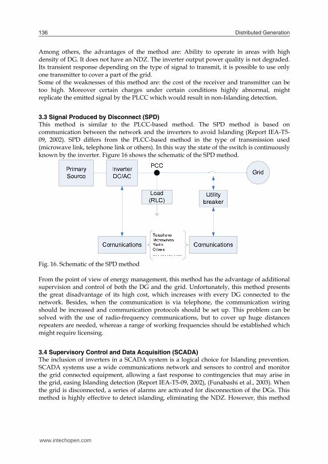
3.3 Signal Produced by Disconnect (SPD) This method is similar to the PLCC-based method. The SPD method is based on communication between the network and the inverters to avoid Islanding (Report IEA-T5-09, 2002). SPD differs from the PLCC-based method in the type of transmission used (microwave link, telephone link or others). In this way the state of the switch is continuously known by the inverter. Figure 16 shows the schematic of the SPD method.
Fig. 16. Schematic of the SPD method From the point of view of energy management, this method has the advantage of additional supervision and control of both the DG and the grid. Unfortunately, this method presents the great disadvantage of its high cost, which increases with every DG connected to the network. Besides, when the communication is via telephone, the communication wiring should be increased and communication protocols should be set up. This problem can be solved with the use of radio-frequency communications, but to cover up huge distances repeaters are needed, whereas a range of working frequencies should be established which might require licensing.
3.4 Supervisory Control and Data Acquisition (SCADA) The inclusion of inverters in a SCADA system is a logical choice for Islanding prevention. SCADA systems use a wide communications network and sensors to control and monitor the grid connected equipment, allowing a fast response to contingencies that may arise in the grid, easing Islanding detection (Report IEA-T5-09, 2002), (Funabashi et al., 2003). When the grid is disconnected, a series of alarms are activated for disconnection of the DGs. This method is highly effective to detect islanding, eliminating the NDZ. However, this method
presents the disadvantage of being too expensive and requiring a large number of sensors and additional features. Furthermore, it is not feasible in small installations.
4. Standards, codes and international recommendations about anti-islanding
Methods, circuits and procedures for anti-Islanding test have been documented in various international and national standards and recommendations. There are a great variety of approaches to verify anti-Islanding detection. Each country will choose its own methods to prevent islanding depending on its requirements. The test methods are generally defined for single and three phase inverters, as well as the requirements of the load to perform the tests. Following, a list of some standards, codes and recommendations concerning anti-Islanding is presented.
IEEE Std. 929-2000, IEEE Recommended Practice for Utility Interface of Photovoltaic (PV) Systems, Sponsored by IEEE Standards Coordinating Committee 21 on Photovoltaics, Published by the IEEE, New York, NY, Apr 2000.
UL1741, UL Standard for Safety for Static Converters and Charge Controllers for
Use in Photovoltaic Power Systems, Underwriters Laboratories, First Edition, May 7, 1999, Revised Jan 2001.
International Standard IEC 62116 DRAFT, Testing Procedure of Islanding
Prevention Measures for Grid Connected Photovoltaic Power Generation Systems, International Electrotechnical Commission.
Guidelines for the Electrical Installation of Grid-connected Photovoltaic (PV)
Systems, Dutch guidelines to comply with NEN1010 (Safety provisions for low voltage installations), EnergieNed and NOVEM, Dec 1998.
JIS C 8962:1997, Testing Procedure of Power Conditioners for Small Photovoltaic
Power Generating Systems, Japanese Industrial Standard, 1997.EN61277, Terrestrial Photovoltaic (PV) Power Generating Systems –General and Guide.
DIN VDE 0126:1999, Automatic Disconnection Facility for Photovoltaic
Installations With a Nominal Output < 4.6 kVA and a Single-phase Parallel Feed by Means of an Inverter Into the Public Grid, (German National Standard for Utility Interconnection of Photovoltaic Systems).
G77, UK Standard for Interconnection of PV and Other Distributed Energy,
Generation, Standard Under Development, Expected Completion, Jan 2002.
www.intechopen.com

Local and Remote Techniques for Islanding Detection in Distributed Generators 137
Among others, the advantages of the method are: Ability to operate in areas with high density of DG. It does not have an NDZ. The inverter output power quality is not degraded. Its transient response depending on the type of signal to transmit, it is possible to use only one transmitter to cover a part of the grid. Some of the weaknesses of this method are: the cost of the receiver and transmitter can be too high. Moreover certain charges under certain conditions highly abnormal, might replicate the emitted signal by the PLCC which would result in non-Islanding detection.
3.3 Signal Produced by Disconnect (SPD) This method is similar to the PLCC-based method. The SPD method is based on communication between the network and the inverters to avoid Islanding (Report IEA-T5-09, 2002). SPD differs from the PLCC-based method in the type of transmission used (microwave link, telephone link or others). In this way the state of the switch is continuously known by the inverter. Figure 16 shows the schematic of the SPD method.
Fig. 16. Schematic of the SPD method From the point of view of energy management, this method has the advantage of additional supervision and control of both the DG and the grid. Unfortunately, this method presents the great disadvantage of its high cost, which increases with every DG connected to the network. Besides, when the communication is via telephone, the communication wiring should be increased and communication protocols should be set up. This problem can be solved with the use of radio-frequency communications, but to cover up huge distances repeaters are needed, whereas a range of working frequencies should be established which might require licensing.
3.4 Supervisory Control and Data Acquisition (SCADA) The inclusion of inverters in a SCADA system is a logical choice for Islanding prevention. SCADA systems use a wide communications network and sensors to control and monitor the grid connected equipment, allowing a fast response to contingencies that may arise in the grid, easing Islanding detection (Report IEA-T5-09, 2002), (Funabashi et al., 2003). When the grid is disconnected, a series of alarms are activated for disconnection of the DGs. This method is highly effective to detect islanding, eliminating the NDZ. However, this method
presents the disadvantage of being too expensive and requiring a large number of sensors and additional features. Furthermore, it is not feasible in small installations.
4. Standards, codes and international recommendations about anti-islanding
Methods, circuits and procedures for anti-Islanding test have been documented in various international and national standards and recommendations. There are a great variety of approaches to verify anti-Islanding detection. Each country will choose its own methods to prevent islanding depending on its requirements. The test methods are generally defined for single and three phase inverters, as well as the requirements of the load to perform the tests. Following, a list of some standards, codes and recommendations concerning anti-Islanding is presented.
IEEE Std. 929-2000, IEEE Recommended Practice for Utility Interface of Photovoltaic (PV) Systems, Sponsored by IEEE Standards Coordinating Committee 21 on Photovoltaics, Published by the IEEE, New York, NY, Apr 2000.
UL1741, UL Standard for Safety for Static Converters and Charge Controllers for
Use in Photovoltaic Power Systems, Underwriters Laboratories, First Edition, May 7, 1999, Revised Jan 2001.
International Standard IEC 62116 DRAFT, Testing Procedure of Islanding
Prevention Measures for Grid Connected Photovoltaic Power Generation Systems, International Electrotechnical Commission.
Guidelines for the Electrical Installation of Grid-connected Photovoltaic (PV)
Systems, Dutch guidelines to comply with NEN1010 (Safety provisions for low voltage installations), EnergieNed and NOVEM, Dec 1998.
JIS C 8962:1997, Testing Procedure of Power Conditioners for Small Photovoltaic
Power Generating Systems, Japanese Industrial Standard, 1997.EN61277, Terrestrial Photovoltaic (PV) Power Generating Systems –General and Guide.
DIN VDE 0126:1999, Automatic Disconnection Facility for Photovoltaic
Installations With a Nominal Output < 4.6 kVA and a Single-phase Parallel Feed by Means of an Inverter Into the Public Grid, (German National Standard for Utility Interconnection of Photovoltaic Systems).
G77, UK Standard for Interconnection of PV and Other Distributed Energy,
Generation, Standard Under Development, Expected Completion, Jan 2002.
www.intechopen.com
Distributed Generation 138
5. Conclusion
In this chapter several techniques for Islanding detection have been presented. These techniques can be classified into two groups depending on their location in the DG system: remote techniques and local techniques. In the first group the detection algorithm is located at the grid side, whereas in the second group the detection method is located at the inverter side. Additionally, the local techniques can be divided into passive techniques, which are based on parameter measurement, and active techniques, which generate disturbances of the inverter output. Additionally, the passive methods do not affect the system THD, but present a NDZ which can be high enough to avoid islanding detection. On the contrary, active methods have the advantage that it is possible to detect Islanding in almost all situations, but they need to introduce a disturbance that could cause instability or distortion in the grid during normal operation, degrading power quality. Finally, the remote or ‘non-resident in the inverter’ methods, which do not affect power quality and have no NDZ, require extra hardware to be implemented, which means higher costs and may not be acceptable in many situations.
6. References
Ciobotaru, M., Agelidis, V. & Teodorescu, R. (2008). Accurate and less-disturbing active anti-islanding method based on PLL for grid-connected PV Inverters, Proc. of IEEE Power Electronics Specialists Conference PESC 2008, pp.4569-4576, Greece.
Ciobotaru, M., Teodorescu, R. & Blaabjerg, F. (2007). On-line grid impedance estimation based on harmonic injection for grid connected PV inverter, Proc. of IEEE International Symposium on Industrial Electronics, pp. 2437–2442, Spain.
Ciobotaru, M., Teodorescu, R., Rodríguez, P., Timbus, A. & Blaabjerg, F. (2007). "Online grid impedance estimation for single-phase grid-connected systems using PQ variations, Proc. of the 35th Annual IEEE Power Electronics Specialists Conference PESC 2007, pp. 2306-2312, U.S.A.
De Mango, F., Liserre, M., Aquila, A.D. & Pigazo, A. (2006). Overview of Anti-Islanding Algorithms for PV Systems. Part I: Passive Methods, Proc. of the 12th International Conference on Power Electronics and Motion Control EPE-PEMC 2006., pp.1878-1883, Slovenia.
De Mango, F., Liserre, M. & Aquila, A.D. (2006). Overview of Anti-Islanding Algorithms for PV Systems. Part II: ActiveMethods, Proc. of 12th International Conference on Power Electronics and Motion Control EPE-PEMC 2006, pp.1884-1889, Slovenia.
Funabashi, T.; Koyanagi, K. & Yokoyama, R. (2003). A review of islanding detection methods for distributed resources, Proc. of IEEE Power Tech 2003, Vol.2, pp. 6, Italy.
Hotta, K., Kitamura, A., Okamoto, M., Takigawa, K., Kobayashi, H. & Ariga, Y. (1993) Islanding prevention measures: demonstration testing at Rokko test center for advanced energy systems, Proc. of the 23rd Annual IEEE Power Electronics Specialists Conference PESC 1993, pp. 1063-1067, Spain.
IEEE 929. (2000). IEEE recommended practice for grid interface of photovoltaic (PV) systems, Institute of Electrical and Electronics Engineers, U.S.A.
Jang, S. & Kim, K. (2004). An islanding detection method for distributed generations using voltage unbalance and total harmonic distortion of current, IEEE Trans. on Power Delivery, Vol. 19, No. 2, pp. 745-752.
Jeong, J.B., Kim, H.J., Back, S.H. & Ahn, K.S. (2005). An improved method for anti-islanding by reactive power control, Proceedings of the 8th International Conference on Electrical Machines and Systems ICEMS 2005, Vol.2, pp. 965-970, China.
Jeraputra, C. & Enjeti, P.N. (2004). Development of a robust anti-islanding algorithm for grid interconnection of distributed fuel cell powered generation, IEEE Trans. on Power Electronics, Vol.19, No.5, pp. 1163 -1170.
John, V., Ye, Z. & Kolwalkar, A. (2004). Investigation of anti-islanding protection of power converter based distributed generators using frequency domain analysis, IEEE Trans. on Power Electronics, Vol. 19, No. 5, pp. 1177 – 1183.
Jung, Y., Choi, J., Yu, B., So, J. & Yu, G. (2005). A Novel Active Frequency Drift Method of Islanding Prevention for the grid-connected Photovoltaic Inverter, Proc. of IEEE Power Electronics Specialists Conference PESC 2005, pp. 1915 – 1921, Germany.
Kitamura, A., Okamoto, M., Yamamoto, F., Nakaji, K., Matsuda, H. & Hotta, K. (1994) Islanding phenomenon elimination study at Rokko test center, Proc. of the 1st IEEE World Conference on Photovoltaic Energy conversion, pp. 759-762, U.S.A.
Kobayashi, H., Takigawa, K. & Hashimoto, E. (1991). Method for Preventing Islanding Phenomenon on Utility Grid with a Number of Small Scale PV Systems, Proc. of the 21st IEEE Photovoltaic Specialists Conference, pp. 695-700, U.S.A.
Liserre, M., Pigazo, A., Dell'Aquila, A. & Moreno, V.M. (2006). An Anti-Islanding Method for Single-Phase Inverters Based on a Grid Voltage Sensorless Control, IEEE Trans. on Industrial Electronics, Vol. 53, No. 5, pp. 1418-1426.
Liu, F., Kang, Y. & Duan, S. (2007). Analysis and optimization of active frequency drift islanding detection method, Proc. of the 22nd Annual IEEE Applied Power Electronics Conference APEC 2007, pp. 1379–1384, U.S.A.
Lopes, L.A.C. & Sun, H. (2006). Performance assessment of active frequency drifting islanding detection methods, IEEE Trans. on Energy Conversion, Vol. 21, No. 1, pp. 171 – 180.
Mahat, P., Zhe, C. & Bak-Jensen, B. (2008). Review of islanding detection methods for distributed generation. Proc of the 3rd International Conference on Electric Utility Deregulation and Restructuring and Power Technologies, pp. 2743-2748, China.
Menon, V. & Nehrir, M. H. (2007). A Hybrid Islanding Detection Technique Using Voltage Unbalance and Frequency Set Point, IEEE Trans. on Power Systems, Vol. 22, No. 1, pp. 442 – 448.
Pietzsch, M. (2004). Convertidores CC/CA para la conexión directa a red de sistemas fotovoltaicos: comparación entre topologías de 2 y 3 niveles, Bachelor thesis, U.P.C, Spain.
Report IEAPVPS T5-09. (2002). Evaluation of islanding detection methods for photovoltaic utility interactive power systems, International Energy Agency Implementing agreement on Photovoltaic Power Systems, U.S.A.
Ropp, M., Aaker, K., Haigh, J. & Sabhah N. (2000). Using Power Line Carrier Communications to Prevent Islanding, Proc. of the 28th IEEE Photovoltaic Specialist Conference, pp. 1675-1678, U.S.A.
Ropp, M., Ginn, J., Stevens, J., Bower, W. & Gonzalez, S. (2006). Simulation and Experimental Study of the Impedance Detection Anti-Islanding Method in the Single-Inverter Case, Proc. of the 4th World Conference of the IEEE on Photovoltaic Energy Conversion, Vol.2, pp.2379-2382, .
www.intechopen.com

Local and Remote Techniques for Islanding Detection in Distributed Generators 139
5. Conclusion
In this chapter several techniques for Islanding detection have been presented. These techniques can be classified into two groups depending on their location in the DG system: remote techniques and local techniques. In the first group the detection algorithm is located at the grid side, whereas in the second group the detection method is located at the inverter side. Additionally, the local techniques can be divided into passive techniques, which are based on parameter measurement, and active techniques, which generate disturbances of the inverter output. Additionally, the passive methods do not affect the system THD, but present a NDZ which can be high enough to avoid islanding detection. On the contrary, active methods have the advantage that it is possible to detect Islanding in almost all situations, but they need to introduce a disturbance that could cause instability or distortion in the grid during normal operation, degrading power quality. Finally, the remote or ‘non-resident in the inverter’ methods, which do not affect power quality and have no NDZ, require extra hardware to be implemented, which means higher costs and may not be acceptable in many situations.
6. References
Ciobotaru, M., Agelidis, V. & Teodorescu, R. (2008). Accurate and less-disturbing active anti-islanding method based on PLL for grid-connected PV Inverters, Proc. of IEEE Power Electronics Specialists Conference PESC 2008, pp.4569-4576, Greece.
Ciobotaru, M., Teodorescu, R. & Blaabjerg, F. (2007). On-line grid impedance estimation based on harmonic injection for grid connected PV inverter, Proc. of IEEE International Symposium on Industrial Electronics, pp. 2437–2442, Spain.
Ciobotaru, M., Teodorescu, R., Rodríguez, P., Timbus, A. & Blaabjerg, F. (2007). "Online grid impedance estimation for single-phase grid-connected systems using PQ variations, Proc. of the 35th Annual IEEE Power Electronics Specialists Conference PESC 2007, pp. 2306-2312, U.S.A.
De Mango, F., Liserre, M., Aquila, A.D. & Pigazo, A. (2006). Overview of Anti-Islanding Algorithms for PV Systems. Part I: Passive Methods, Proc. of the 12th International Conference on Power Electronics and Motion Control EPE-PEMC 2006., pp.1878-1883, Slovenia.
De Mango, F., Liserre, M. & Aquila, A.D. (2006). Overview of Anti-Islanding Algorithms for PV Systems. Part II: ActiveMethods, Proc. of 12th International Conference on Power Electronics and Motion Control EPE-PEMC 2006, pp.1884-1889, Slovenia.
Funabashi, T.; Koyanagi, K. & Yokoyama, R. (2003). A review of islanding detection methods for distributed resources, Proc. of IEEE Power Tech 2003, Vol.2, pp. 6, Italy.
Hotta, K., Kitamura, A., Okamoto, M., Takigawa, K., Kobayashi, H. & Ariga, Y. (1993) Islanding prevention measures: demonstration testing at Rokko test center for advanced energy systems, Proc. of the 23rd Annual IEEE Power Electronics Specialists Conference PESC 1993, pp. 1063-1067, Spain.
IEEE 929. (2000). IEEE recommended practice for grid interface of photovoltaic (PV) systems, Institute of Electrical and Electronics Engineers, U.S.A.
Jang, S. & Kim, K. (2004). An islanding detection method for distributed generations using voltage unbalance and total harmonic distortion of current, IEEE Trans. on Power Delivery, Vol. 19, No. 2, pp. 745-752.
Jeong, J.B., Kim, H.J., Back, S.H. & Ahn, K.S. (2005). An improved method for anti-islanding by reactive power control, Proceedings of the 8th International Conference on Electrical Machines and Systems ICEMS 2005, Vol.2, pp. 965-970, China.
Jeraputra, C. & Enjeti, P.N. (2004). Development of a robust anti-islanding algorithm for grid interconnection of distributed fuel cell powered generation, IEEE Trans. on Power Electronics, Vol.19, No.5, pp. 1163 -1170.
John, V., Ye, Z. & Kolwalkar, A. (2004). Investigation of anti-islanding protection of power converter based distributed generators using frequency domain analysis, IEEE Trans. on Power Electronics, Vol. 19, No. 5, pp. 1177 – 1183.
Jung, Y., Choi, J., Yu, B., So, J. & Yu, G. (2005). A Novel Active Frequency Drift Method of Islanding Prevention for the grid-connected Photovoltaic Inverter, Proc. of IEEE Power Electronics Specialists Conference PESC 2005, pp. 1915 – 1921, Germany.
Kitamura, A., Okamoto, M., Yamamoto, F., Nakaji, K., Matsuda, H. & Hotta, K. (1994) Islanding phenomenon elimination study at Rokko test center, Proc. of the 1st IEEE World Conference on Photovoltaic Energy conversion, pp. 759-762, U.S.A.
Kobayashi, H., Takigawa, K. & Hashimoto, E. (1991). Method for Preventing Islanding Phenomenon on Utility Grid with a Number of Small Scale PV Systems, Proc. of the 21st IEEE Photovoltaic Specialists Conference, pp. 695-700, U.S.A.
Liserre, M., Pigazo, A., Dell'Aquila, A. & Moreno, V.M. (2006). An Anti-Islanding Method for Single-Phase Inverters Based on a Grid Voltage Sensorless Control, IEEE Trans. on Industrial Electronics, Vol. 53, No. 5, pp. 1418-1426.
Liu, F., Kang, Y. & Duan, S. (2007). Analysis and optimization of active frequency drift islanding detection method, Proc. of the 22nd Annual IEEE Applied Power Electronics Conference APEC 2007, pp. 1379–1384, U.S.A.
Lopes, L.A.C. & Sun, H. (2006). Performance assessment of active frequency drifting islanding detection methods, IEEE Trans. on Energy Conversion, Vol. 21, No. 1, pp. 171 – 180.
Mahat, P., Zhe, C. & Bak-Jensen, B. (2008). Review of islanding detection methods for distributed generation. Proc of the 3rd International Conference on Electric Utility Deregulation and Restructuring and Power Technologies, pp. 2743-2748, China.
Menon, V. & Nehrir, M. H. (2007). A Hybrid Islanding Detection Technique Using Voltage Unbalance and Frequency Set Point, IEEE Trans. on Power Systems, Vol. 22, No. 1, pp. 442 – 448.
Pietzsch, M. (2004). Convertidores CC/CA para la conexión directa a red de sistemas fotovoltaicos: comparación entre topologías de 2 y 3 niveles, Bachelor thesis, U.P.C, Spain.
Report IEAPVPS T5-09. (2002). Evaluation of islanding detection methods for photovoltaic utility interactive power systems, International Energy Agency Implementing agreement on Photovoltaic Power Systems, U.S.A.
Ropp, M., Aaker, K., Haigh, J. & Sabhah N. (2000). Using Power Line Carrier Communications to Prevent Islanding, Proc. of the 28th IEEE Photovoltaic Specialist Conference, pp. 1675-1678, U.S.A.
Ropp, M., Ginn, J., Stevens, J., Bower, W. & Gonzalez, S. (2006). Simulation and Experimental Study of the Impedance Detection Anti-Islanding Method in the Single-Inverter Case, Proc. of the 4th World Conference of the IEEE on Photovoltaic Energy Conversion, Vol.2, pp.2379-2382, .
www.intechopen.com

Distributed Generation 140
Sanchis, P., Marroyo, L. & Coloma, J. (2005). Design methodology for the frequency shift method of islanding prevention and analysis of its detection capability, Progress in Photovoltaics: Research and Applications, Vol. 13, No. 5, pp. 409-428, 2005.
Sun, H., Lopes, L.A.C. & Zhixiang, L. (2004). Analysis and comparison of islanding detection methods using a new load parameter space, Proc. of the 30th Annual Conference of the IEEE Industrial Electronics Society IECON 2004, Vol. 2, pp. 1172 – 1177, Korea.
Wang, X., Freitas, W., Xu, W. & Dinavahi, V. (2007). Impact of DG Interface Controls on the Sandia Frequency Shift Antiislanding Method, IEEE Trans. on Energy Conversion, Vol. 22, No. 3, pp. 792 – 794.
Xu, W., Zhang, G., Li, C.,Wang, W., Wang, G. & Kliber, J. (2007). A power line signaling based technique for anti-islanding protection of distributed generators—part I: scheme and analysis, IEEE Trans. on Power Delivery, Vol. 22, No. 3, pp. 1758-1766.
Ye, Z., Kolwalkar, A., Zhang, Y.,Du, P. & Walling, R. (2004). Evaluation of anti-islanding schemes based on non detection zone concept, IEEE Trans. on Power Electronics, Vol. 19, No. 5, pp. 1171 – 1176.
Ye, Z., Li, L., Garces, L., Wang, C., Zhang, R., Dame, M., Walling, R. & Miller, N. (2004). A new family of active antiislanding schemes based on DQ implementation for grid-connected inverters, Proc. of the 35th Annual IEEE Power Electronics Specialists Conference PESC 2004, pp. 235-241, Germany.
Zhang, C., Liu, W., San, G. & Wu, W. (2006). A Novel Active Islanding Detection Method of Grid-connected Photovoltaic Inverters Based on Current-Disturbing, Proc. of the 5th International Power Electronics and Motion Control Conference IPEMC'06, Vol. 3, pp. 1-4, China.
www.intechopen.com

Distributed GenerationEdited by D N Gaonkar
ISBN 978-953-307-046-9Hard cover, 406 pagesPublisher InTechPublished online 01, February, 2010Published in print edition February, 2010
In the recent years the electrical power utilities have undergone rapid restructuring process worldwide. Indeed,with deregulation, advancement in technologies and concern about the environmental impacts, competition isparticularly fostered in the generation side, thus allowing increased interconnection of generating units to theutility networks. These generating sources are called distributed generators (DG) and defined as the plantwhich is directly connected to distribution network and is not centrally planned and dispatched. These are alsocalled embedded or dispersed generation units. The rating of the DG systems can vary between few kW to ashigh as 100 MW. Various new types of distributed generator systems, such as microturbines and fuel cells inaddition to the more traditional solar and wind power are creating significant new opportunities for theintegration of diverse DG systems to the utility. Interconnection of these generators will offer a number ofbenefits such as improved reliability, power quality, efficiency, alleviation of system constraints along with theenvironmental benefits. Unlike centralized power plants, the DG units are directly connected to the distributionsystem; most often at the customer end. The existing distribution networks are designed and operated in radialconfiguration with unidirectional power flow from centralized generating station to customers. The increase ininterconnection of DG to utility networks can lead to reverse power flow violating fundamental assumption intheir design. This creates complexity in operation and control of existing distribution networks and offers manytechnical challenges for successful introduction of DG systems. Some of the technical issues are islanding ofDG, voltage regulation, protection and stability of the network. Some of the solutions to these problems includedesigning standard interface control for individual DG systems by taking care of their diverse characteristics,finding new ways to/or install and control these DG systems and finding new design for distribution system. DGhas much potential to improve distribution system performance. The use of DG strongly contributes to a clean,reliable and cost effective energy for future. This book deals with several aspects of the DG systems such asbenefits, issues, technology interconnected operation, performance studies, planning and design. Severalauthors have contributed to this book aiming to benefit students, researchers, academics, policy makers andprofessionals. We are indebted to all the people who either directly or indirectly contributed towards thepublication of this book.
How to referenceIn order to correctly reference this scholarly work, feel free to copy and paste the following:
Cesar Trujillo, David Velasco, Emilio Figueres and Gabriel Garcera (2010). Local and Remote Techniques forIslanding Detection in Distributed Generators, Distributed Generation, D N Gaonkar (Ed.), ISBN: 978-953-307-046-9, InTech, Available from: http://www.intechopen.com/books/distributed-generation/local-and-remote-techniques-for-islanding-detection-in-distributed-generators
www.intechopen.com

InTech EuropeUniversity Campus STeP Ri Slavka Krautzeka 83/A 51000 Rijeka, Croatia Phone: +385 (51) 770 447 Fax: +385 (51) 686 166www.intechopen.com
InTech ChinaUnit 405, Office Block, Hotel Equatorial Shanghai No.65, Yan An Road (West), Shanghai, 200040, China
Phone: +86-21-62489820 Fax: +86-21-62489821

© 2010 The Author(s). Licensee IntechOpen. This chapter is distributedunder the terms of the Creative Commons Attribution-NonCommercial-ShareAlike-3.0 License, which permits use, distribution and reproduction fornon-commercial purposes, provided the original is properly cited andderivative works building on this content are distributed under the samelicense.