Embed Size (px)
Citation preview
Motoman® NX100 Controller
LoadWorld® IIISystem Manualfor IA20 robots
Part Number: 153770-1CDRevision: 0
Motoman, Incorporated 805 Liberty LaneWest Carrollton, Ohio 45449 USA937.847.6200 (Voice)937.847.6277 (Fax)937.847.3200 (24-Hour Support)[email protected]

COMPLETE OUR ONLINE SURVEYMotoman is committed to total customer satisfaction! Please give us your feedback on the technical manuals you
received with your Motoman robotic solution.
To participate, go to the following website:
http://www.motoman.com/forms/techpubs.asp
The information contained within this document is the proprietary property ofMotoman, Inc., and may not be copied, reproduced or transmitted to otherparties without the expressed written authorization of Motoman, Inc.
©2007 by MOTOMAN®
All Rights Reserved
Because we are constantly improving our products, we reserve the right to changespecifications without notice.
MOTOMAN® is a registered trademark of YASKAWA Electric Manufacturing.
LoadWorld® III153770-1
Chapter 1 Introduction . . . . . . . . . . . . . . . . . . . . . . . . . . . . . . . . . . . . . . . . . . . . . . . . . . . . . . . . . . . . . . . . . . . . . . 1
1.1 About This Document . . . . . . . . . . . . . . . . . . . . . . . . . . . . . . . . . . . . . . . . . . . . . . . . . . . . 11.2 System Overview . . . . . . . . . . . . . . . . . . . . . . . . . . . . . . . . . . . . . . . . . . . . . . . . . . . . . . . . 2
1.2.1 System Layout . . . . . . . . . . . . . . . . . . . . . . . . . . . . . . . . . . . . . . . . . . . . . . . . . . . . . 31.2.2 Major Components . . . . . . . . . . . . . . . . . . . . . . . . . . . . . . . . . . . . . . . . . . . . . . . . . 31.2.3 Optional Equipment . . . . . . . . . . . . . . . . . . . . . . . . . . . . . . . . . . . . . . . . . . . . . . . . 3
1.3 Reference Documentation . . . . . . . . . . . . . . . . . . . . . . . . . . . . . . . . . . . . . . . . . . . . . . . . . 41.4 Customer Support Information . . . . . . . . . . . . . . . . . . . . . . . . . . . . . . . . . . . . . . . . . . . . . 4
Chapter 2 Safety . . . . . . . . . . . . . . . . . . . . . . . . . . . . . . . . . . . . . . . . . . . . . . . . . . . . . . . . . . . . . . . . . . . . . . . . . . . 5
2.1 Introduction . . . . . . . . . . . . . . . . . . . . . . . . . . . . . . . . . . . . . . . . . . . . . . . . . . . . . . . . . . . . 52.2 Standard Conventions . . . . . . . . . . . . . . . . . . . . . . . . . . . . . . . . . . . . . . . . . . . . . . . . . . . . 62.3 General Safeguarding Tips . . . . . . . . . . . . . . . . . . . . . . . . . . . . . . . . . . . . . . . . . . . . . . . . . 62.4 Mechanical Safety Devices . . . . . . . . . . . . . . . . . . . . . . . . . . . . . . . . . . . . . . . . . . . . . . . . . 72.5 Installation Safety . . . . . . . . . . . . . . . . . . . . . . . . . . . . . . . . . . . . . . . . . . . . . . . . . . . . . . . . 72.6 Programming, Operation, and Maintenance Safety . . . . . . . . . . . . . . . . . . . . . . . . . . . . . . 8
Chapter 3 Equipment Description . . . . . . . . . . . . . . . . . . . . . . . . . . . . . . . . . . . . . . . . . . . . . . . . . . . . . . . . . . . . . 9
3.1 Robot Description . . . . . . . . . . . . . . . . . . . . . . . . . . . . . . . . . . . . . . . . . . . . . . . . . . . . . . . 93.2 NX100 Controller . . . . . . . . . . . . . . . . . . . . . . . . . . . . . . . . . . . . . . . . . . . . . . . . . . . . . . . 93.3 Programming Pendant . . . . . . . . . . . . . . . . . . . . . . . . . . . . . . . . . . . . . . . . . . . . . . . . . . . 103.4 Safety Features . . . . . . . . . . . . . . . . . . . . . . . . . . . . . . . . . . . . . . . . . . . . . . . . . . . . . . . . . 12
3.4.1 Safety Fencing . . . . . . . . . . . . . . . . . . . . . . . . . . . . . . . . . . . . . . . . . . . . . . . . . . . . 123.4.2 Emergency Stop (E-Stop) . . . . . . . . . . . . . . . . . . . . . . . . . . . . . . . . . . . . . . . . . . . . 123.4.3 Programming Pendant ENABLE Switch . . . . . . . . . . . . . . . . . . . . . . . . . . . . . . . . 133.4.4 Emergency Braking System . . . . . . . . . . . . . . . . . . . . . . . . . . . . . . . . . . . . . . . . . . 133.4.5 Interlocked Work Cell Door . . . . . . . . . . . . . . . . . . . . . . . . . . . . . . . . . . . . . . . . . 13
Chapter 4 Installation . . . . . . . . . . . . . . . . . . . . . . . . . . . . . . . . . . . . . . . . . . . . . . . . . . . . . . . . . . . . . . . . . . . . . . 15
4.1 Required Materials . . . . . . . . . . . . . . . . . . . . . . . . . . . . . . . . . . . . . . . . . . . . . . . . . . . . . . 154.1.1 Customer-Supplied Items . . . . . . . . . . . . . . . . . . . . . . . . . . . . . . . . . . . . . . . . . . . 164.1.2 Recommended List of Hand Tools and Equipment . . . . . . . . . . . . . . . . . . . . . . . . 16
4.2 Site Preparation . . . . . . . . . . . . . . . . . . . . . . . . . . . . . . . . . . . . . . . . . . . . . . . . . . . . . . . . 164.3 Removal of System Components from Shipping Skids . . . . . . . . . . . . . . . . . . . . . . . . . . . 194.4 Component Installation . . . . . . . . . . . . . . . . . . . . . . . . . . . . . . . . . . . . . . . . . . . . . . . . . . 19
4.4.1 Place System Components . . . . . . . . . . . . . . . . . . . . . . . . . . . . . . . . . . . . . . . . . . . 194.4.2 Level and Anchor System Components . . . . . . . . . . . . . . . . . . . . . . . . . . . . . . . . . 20
4.5 Cable Connections . . . . . . . . . . . . . . . . . . . . . . . . . . . . . . . . . . . . . . . . . . . . . . . . . . . . . . 214.5.1 Connection to Earth Ground . . . . . . . . . . . . . . . . . . . . . . . . . . . . . . . . . . . . . . . . . 21
Final

System Manual
4.5.2 Connection to Local Electrical Service . . . . . . . . . . . . . . . . . . . . . . . . . . . . . . . . . . 224.5.2.1 NX100 Controller . . . . . . . . . . . . . . . . . . . . . . . . . . . . . . . . . . . . . . . . . . . . 22
4.6 Safety / Operation Check . . . . . . . . . . . . . . . . . . . . . . . . . . . . . . . . . . . . . . . . . . . . . . . . . 22
Chapter 5 Operation . . . . . . . . . . . . . . . . . . . . . . . . . . . . . . . . . . . . . . . . . . . . . . . . . . . . . . . . . . . . . . . . . . . . . . . 25
5.1 Programming . . . . . . . . . . . . . . . . . . . . . . . . . . . . . . . . . . . . . . . . . . . . . . . . . . . . . . . . . . 255.2 Daily Operation . . . . . . . . . . . . . . . . . . . . . . . . . . . . . . . . . . . . . . . . . . . . . . . . . . . . . . . . 26
5.2.1 Start-Up . . . . . . . . . . . . . . . . . . . . . . . . . . . . . . . . . . . . . . . . . . . . . . . . . . . . . . . . . 265.2.2 Robot Home Position . . . . . . . . . . . . . . . . . . . . . . . . . . . . . . . . . . . . . . . . . . . . . . 265.2.3 Master Job . . . . . . . . . . . . . . . . . . . . . . . . . . . . . . . . . . . . . . . . . . . . . . . . . . . . . . . 275.2.4 Operation Cycle . . . . . . . . . . . . . . . . . . . . . . . . . . . . . . . . . . . . . . . . . . . . . . . . . . . 275.2.5 Shutdown . . . . . . . . . . . . . . . . . . . . . . . . . . . . . . . . . . . . . . . . . . . . . . . . . . . . . . . 27
5.3 System Recovery . . . . . . . . . . . . . . . . . . . . . . . . . . . . . . . . . . . . . . . . . . . . . . . . . . . . . . . . 285.3.1 Alarms and Errors . . . . . . . . . . . . . . . . . . . . . . . . . . . . . . . . . . . . . . . . . . . . . . . . . 28
5.3.1.1 Error Messages . . . . . . . . . . . . . . . . . . . . . . . . . . . . . . . . . . . . . . . . . . . . . . . 285.3.1.2 Minor Alarms . . . . . . . . . . . . . . . . . . . . . . . . . . . . . . . . . . . . . . . . . . . . . . . 285.3.1.3 Major Alarms . . . . . . . . . . . . . . . . . . . . . . . . . . . . . . . . . . . . . . . . . . . . . . . . 28
5.3.2 E-Stop Recovery . . . . . . . . . . . . . . . . . . . . . . . . . . . . . . . . . . . . . . . . . . . . . . . . . . . 295.3.3 Brake Release . . . . . . . . . . . . . . . . . . . . . . . . . . . . . . . . . . . . . . . . . . . . . . . . . . . . . 29
Chapter 6 Maintenance . . . . . . . . . . . . . . . . . . . . . . . . . . . . . . . . . . . . . . . . . . . . . . . . . . . . . . . . . . . . . . . . . . . . . 31
Appendix A Anchoring . . . . . . . . . . . . . . . . . . . . . . . . . . . . . . . . . . . . . . . . . . . . . . . . . . . . . . . . . . . . . . . . . . . . . . . 33
Appendix B Gripper Assemblies . . . . . . . . . . . . . . . . . . . . . . . . . . . . . . . . . . . . . . . . . . . . . . . . . . . . . . . . . . . . . . . 35
B.1 Illustrated Parts List . . . . . . . . . . . . . . . . . . . . . . 35B.1.1 Explanation of Parts List . . . . . . . . . . . . . . . . . . 35
B.2 Parts List . . . . . . . . . . . . . . . . . . . . . . . . . 36B.2.2 Explanation of Parts List Arrangement . . . . . . . . . . . . . . 36B.2.3 Symbols and Abbreviations . . . . . . . . . . . . . . . . . . 36
B.3 153627-1 90D (90-Degree) . . . . . . . . . . . . . . . . . . . . 37B.4 153627-2 BTB (Back-to-Back) . . . . . . . . . . . . . . . . . . . 39B.5 153627-3 2I (Inline) . . . . . . . . . . . . . . . . . . . . . . 41
Final
LoadWorld® III153770-1
Chapter 1
Introduction
1.1 About This Document
This System Manual provides an overview of Motoman’s LoadWorld® III system. For detailed information on any specific system component listed in this document, please refer to the documentation package that is included with your LoadWorld® III system (refer to Section 1.3).
✍ Note: This manual documents a standard Motoman system. If your system is custom or modified, please use this manual in conjunction with the drawings, schematics, and parts listing (Bill of Material) for your specific system. The drawings, schematics, and parts listing are included in the documentation package supplied with your Motoman system.
This System Manual contains the following chapters –
CHAPTER 1 – INTRODUCTION
This chapter introduces the LoadWorld® III System Manual, provides an overview of the LoadWorld® III system, lists reference documents that are included with the documentation package, and provides Motoman Customer Support contact information.CHAPTER 2 – SAFETYThis chapter provides general information regarding the safe installation, maintenance, and operation of the LoadWorld® III system.CHAPTER 3 – DESCRIPTION OF EQUIPMENT
This chapter describes the major components of the LoadWorld® III system. CHAPTER 4 – INSTALLATION
This chapter provides installation instructions for the LoadWorld® III system components.CHAPTER 5 – OPERATION
This chapter provides an overview of the LoadWorld® III system operation — start-up, loading, normal operations, fault recovery, and system shutdown.CHAPTER 6 – MAINTENANCEThis chapter provides a listing of preventive maintenance suggestions for certain components of the LoadWorld® III system.APPENDIX A – ANCHORING
Appendix A gives foundation and anchoring suggestions for the LoadWorld® III system components that require anchoring.
Final page 1
System Manual Chapter 1 Introduction
1.2 System Overview
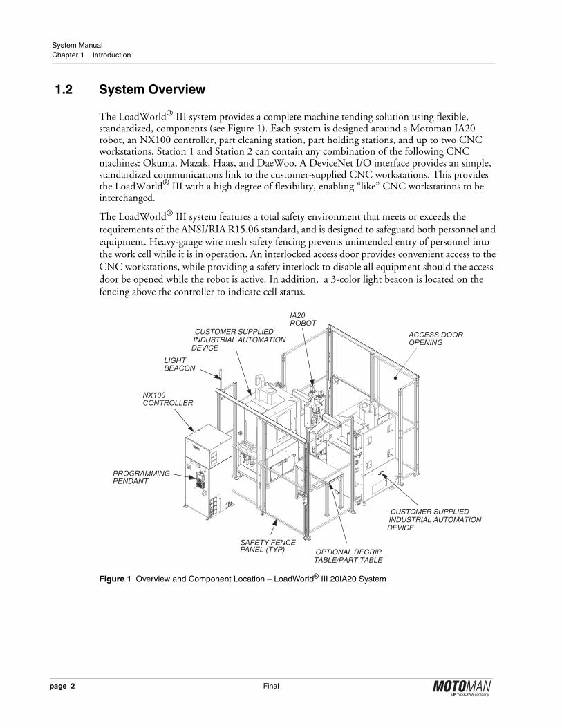
The LoadWorld® III system provides a complete machine tending solution using flexible, standardized, components (see Figure 1). Each system is designed around a Motoman IA20 robot, an NX100 controller, part cleaning station, part holding stations, and up to two CNC workstations. Station 1 and Station 2 can contain any combination of the following CNC machines: Okuma, Mazak, Haas, and DaeWoo. A DeviceNet I/O interface provides an simple, standardized communications link to the customer-supplied CNC workstations. This provides the LoadWorld® III with a high degree of flexibility, enabling “like” CNC workstations to be interchanged.
The LoadWorld® III system features a total safety environment that meets or exceeds the requirements of the ANSI/RIA R15.06 standard, and is designed to safeguard both personnel and equipment. Heavy-gauge wire mesh safety fencing prevents unintended entry of personnel into the work cell while it is in operation. An interlocked access door provides convenient access to the CNC workstations, while providing a safety interlock to disable all equipment should the access door be opened while the robot is active. In addition, a 3-color light beacon is located on the fencing above the controller to indicate cell status.
Figure 1 Overview and Component Location – LoadWorld® III 20IA20 System
NX100CONTROLLER
PROGRAMMINGPENDANT
SAFETY FENCEPANEL (TYP)
ACCESS DOOROPENING
IA20ROBOT
CUSTOMER SUPPLIEDINDUSTRIAL AUTOMATIONDEVICE
CUSTOMER SUPPLIEDINDUSTRIAL AUTOMATIONDEVICE
LIGHTBEACON
OPTIONAL REGRIPTABLE/PART TABLE
page 2 Final
LoadWorld® III153770-1
1.2.1 System Layout
Major components of the LoadWorld® III system are anchored individually to the floor, as this system does not use common equipment bases. Heavy-gauge, wire mesh safety fencing is provided for installation at the customer’s location. When installed, this safety fencing completely encloses the work cell. The NX100 controller is located outside of the work cell. All system controls, including those on the programming pendant and NX100 controller, are safely accessible from outside the LoadWorld® III work cell (see Figure 1 for location of these components).
1.2.2 Major Components
The LoadWorld® III system includes the following major components –
• Motoman IA20 manipulator
• NX100 controller
• Programming Pendant
• Safety equipment –
• Heavy gauge, wire-mesh safety fencing
• Interlocked safety light curtain system
• Interlocked work cell entry door
• BTB Gripper and Valve Module
• Standard Machine Interface
1.2.3 Optional Equipment
The LoadWorld® III series is configured to enable the user to pick optional periphery equipment as required for their specific requirements. The following optional equipment and pre-engineered modules are available for use with the LoadWorld® III system –
All modules are equipped with plug-and-play electrical connections for easy integration.
• Protective Robot Jacket• Infeed Roller Conveyor(s)• Loop Pallet Conveyor(s)• Pallet Outfeed Conveyor(s)• Upper Arm Valve Modules for Two and
Three Jaw Grippers• MSR-200 Positioner Kit
• Dual Gripper End-Of-Arm Tools (three configurations and three sizes)
• Part Holding Stand• Part Regrip Stand• Part Marker Stand• Pallet Floor Locator
Final page 3
System Manual Chapter 1 Introduction
1.3 Reference Documentation
For additional information on individual LoadWorld® III components, refer to the following documentation that is included with your LoadWorld® III system –
• Motoman IA20 Manipulator Manual (P/N 151529-1)
• Motoman NX100 Controller Manual (P/N 149201-1)
• Motoman NX100 Maintenance Manual (P/N 150133-1)
• Motoman NX100 Operator's Manual for Handling (P/N 149231-1)
• Motoman NX100 Concurrent I/O Parameter Manual (P/N 149230-1)
• Motoman INFORM User’s Manual (P/N 150078-1)
• Vendor manuals for system components not manufactured by Motoman
1.4 Customer Support Information
If you need technical assistance with your LoadWorld® III system, please contact Motoman Customer Support at the following 24-hour telephone number –
Please have the following information ready before you call –• SYSTEM — LoadWorld® III 10IA20 or 20IA20
• ROBOTS — IA20
• CONTROLLER — NX100
• PRIMARY APPLICATION — Handling
• SOFTWARE VERSION — Access this information on the Programming Pendant display screen by selecting MAIN MENU SYSTEM INFO VERSION
• ROBOT SERIAL No — Located on data plate of robot
• ROBOT SALES ORDER No — Located on data plate of NX100 controller
• WARRANTY ID CODE — Located on back of the Programming Pendant
937. 847. 3200
page 4 Final

LoadWorld® III153770-1
Chapter 2
Safety
2.1 Introduction
It is the purchaser’s responsibility to ensure that all local, county, state, andnational codes, regulations, rules, or laws relating to safety and safe operatingconditions for each installation are met and followed.
We suggest that you obtain and review a copy of the ANSI/RIA National Safety Standard for Industrial Robots and Robot Systems. This information can be obtained from the Robotic Industries Association by requesting ANSI/RIA R15.06-1999.
Here is RIA contact information –
Robotic Industries Association900 Victors WayP.O. Box 3724
Ann Arbor, Michigan 48106TEL: (734) 994-6088FAX: (734) 994-3338
www.roboticsonline.com
Ultimately, the best safeguard is trained personnel. The user is responsible for providing personnel who are adequately trained to operate, program, and maintain the robot cell. THE ROBOT MUST NOT BE OPERATED BY PERSONNEL WHO HAVE NOT BEEN TRAINED!
We recommend that all personnel who intend to operate, program, repair, or use the robot system be trained in an approved Motoman training course and become familiar with the proper operation of the system.
Final page 5
System Manual Chapter 2 Safety
This safety chapter addresses the following –
• Standard Conventions (Section 2.2)
• General Safeguarding Tips (Section 2.3)
• Mechanical Safety Devices (Section 2.4)
• Installation Safety (Section 2.5)
• Programming, Operation, and Maintenance Safety (Section 2.6)
2.2 Standard Conventions
This manual includes the following alerts – in descending order of severity – that are essential to the safety of personnel and equipment. As you read this manual, pay close attention to these alerts to insure safety when installing, operating, programming, and maintaining this equipment.
!DANGER!Information appearing in a DANGER concerns the protection of personnel from the immediate and imminent hazards that, if not avoided, will result in immediate, serious personal injury or loss of life in addition to equipment damage.
!WARNING!Information appearing in a WARNING concerns the protection of personnel and equipment from potential hazards that can result in personal injury or loss of life in addition to equipment damage.
!CAUTION!Information appearing in a CAUTION concerns the protection of personnel and equipment, software, and data from hazards that can result in minor personal injury or equipment damage.
✍ Note: Information appearing in a Note provides additional information which is helpful in understanding the item being explained.
2.3 General Safeguarding Tips
All operators, programmers, plant and tooling engineers, maintenance personnel, supervisors, and anyone working near the robot must become familiar with the operation of this equipment. All personnel involved with the operation of the equipment must understand potential dangers of operation. General safeguarding tips are as follows –
• Improper operation can result in personal injury and/or damage to the equipment. Only trained personnel familiar with the operation of this robot, the operator's manuals, the system equipment, and options and accessories should be permitted to operate this robot system.
• Do not enter the robot cell while it is in automatic operation. Programmers must have the teach pendant when they enter the robot cell.
page 6 Final

LoadWorld® III153770-1
• Improper connections can damage the robot. All connections must be made within the standard voltage and current ratings of the robot I/O (Inputs and Outputs).
• The robot must be placed in Emergency Stop (E-Stop) mode whenever it is not in use.
• In accordance with ANSI/RIA R15.06-1999, section 4.2.5, Sources of Energy, use lockout/tagout procedures during equipment maintenance. Refer also to Section 1910.147 (29CFR, Part 1910), Occupational Safety and Health Standards for General Industry (OSHA).
2.4 Mechanical Safety Devices
The safe operation of the robot, positioner, auxiliary equipment, and system is ultimately the user's responsibility. The conditions under which the equipment will be operated safely should be reviewed by the user. The user must be aware of the various national codes, ANSI/RIA R15.06-1999 safety standards, and other local codes that may pertain to the installation and use of industrial equipment. Additional safety measures for personnel and equipment may be required depending on system installation, operation, and/or location.
The following safety equipment is provided as standard –
• Safety fences and barriers
• Light curtains and/or safety mats
• Door interlocks
• Emergency stop palm buttons located on operator station, robot controller, and programming pendant
Check all safety equipment frequently for proper operation. Repair or replace any non-functioning safety equipment immediately.
2.5 Installation Safety
Safe installation is essential for protection of people and equipment. The following suggestions are intended to supplement, but not replace, existing federal, local, and state laws and regulations. Additional safety measures for personnel and equipment may be required depending on system installation, operation, and/or location. Installation tips are as follows –
• Be sure that only qualified personnel familiar with national codes, local codes, and ANSI/RIA R15.06-1999 safety standards are permitted to install the equipment.
• Identify the work envelope of each robot with floor markings, signs, and barriers.
• Position all controllers outside the robot work envelope.
• Whenever possible, install safety fences to protect against unauthorized entry into the work envelope.
• Eliminate areas where personnel might get trapped between a moving robot and other equipment (pinch points).
• Provide sufficient room inside the workcell to permit safe teaching and maintenance procedures.
Final page 7

System Manual Chapter 2 Safety
2.6 Programming, Operation, and Maintenance Safety
All operators, programmers, plant and tooling engineers, maintenance personnel, supervisors, and anyone working near the robot must become familiar with the operation of this equipment. Improper operation can result in personal injury and/or damage to the equipment. Only trained personnel familiar with the operation, manuals, electrical design, and equipment interconnections of this robot should be permitted to program, operate, and maintain the system. All personnel involved with the operation of the equipment must understand potential dangers of operation.
• Inspect the robot and work envelope to be sure no potentially hazardous conditions exist. Be sure the area is clean and free of water, oil, debris, etc.
• Be sure that all safeguards are in place. Check all safety equipment for proper operation. Repair or replace any non-functioning safety equipment immediately.
• Do not enter the robot cell while it is in automatic operation. Be sure that only the person holding the programming pendant enters the workcell.
• Check the E-Stop button on the programming pendant for proper operation before programming. The robot must be placed in Emergency Stop (E-Stop) mode whenever it is not in use.
• Back up all programs and jobs onto suitable media before program changes are made. To avoid loss of information, programs, or jobs, a backup must always be made before any service procedures are done and before any changes are made to options, accessories, or equipment.
• Any modifications to PART 1, System Section, of the robot controller concurrent I/O program can cause severe personal injury or death, as well as damage to the robot! Do not make any modifications to PART 1, System Section. Making any changes without the written permission of Motoman will VOID YOUR WARRANTY!
• Some operations require standard passwords and some require special passwords. Special passwords are for Motoman use only. YOUR WARRANTY WILL BE VOID if you use these special passwords.
• The robot controller allows modifications of PART 2, User Section, of the concurrent I/O program and modifications to controller parameters for maximum robot performance. Great care must be taken when making these modifications. All modifications made to the controller will change the way the robot operates and can cause severe personal injury or death, as well as damage the robot and other parts of the system. Double-check all modifications under every mode of robot operation to ensure that you have not created hazards or dangerous situations.
• Check and test any new or modified program at low speed for at least one full cycle.
• This equipment has multiple sources of electrical supply. Electrical interconnections are made between the controller and other equipment. Disconnect and lockout/tagout all electrical circuits before making any modifications or connections.
• Do not perform any maintenance procedures before reading and understanding the proper procedures in the appropriate manual.
• Use proper replacement parts.
• Improper connections can damage the robot. All connections must be made within the standard voltage and current ratings of the robot I/O (Inputs and Outputs).
page 8 Final

LoadWorld® III153770-1
Chapter 3
Equipment Description
3.1 Robot Description
The LoadWorld® III system uses the Motoman IA20 seven-axis robot specifically designed for loading applications. The IA20 robot has a payload capability of 20 kg (44.1 lbs.), and features a horizontal reach of 910 mm (35.8 inches) and features a relative positioning accuracy of ±0.1 mm (±0.004 inch). An internal cabling design provides high flexibility and streamlines the robot profile, allowing access into confined spaces. The robot’s revolutionary 7-axis actuator-driven design enables amazing freedom of movement, coupled with the ability to maneuver in very tight areas. Wrist performance characteristics are best-in-class.
For additional information on the Motoman IA20 robot, please refer to the IA20 Manipulator Manual included with your LoadWorld® III system documentation package (refer to Section 1.3).
3.2 NX100 Controller
The NX100 robotic controller, shown in Figure 2, features a Windows® CE programming pendant with color touch screen, high-speed processing, built-in Ethernet, and a robust PC architecture. The NX100 easily handles multiple tasks and can control up to four robots (up to 36 axes, including robots and external axes), and I/O devices. Advanced Robot Motion (ARM) control provides high-performance path accuracy and vibration control.
The NX100 coordinates the operation of the LoadWorld® III system. It controls manipulator movement, processes input and output signals, and provides the signals to operate the CNC workstations. It maintains variable data and performs numeric processing to convert to and from different coordinate systems. In addition, the controller provides main logic functions, servo control, program and constant data memory, and power distribution. For more information, refer to the controller manual that came with your system.The NX100 controller features an embedded real-time operating system (RTOS) and is programmed with the Motoman INFORM programming language.
Final page 9

System Manual Chapter 3 Equipment Description
Figure 2 NX100 Controller
3.3 Programming Pendant
The Programming Pendant (see Figure 3) provides the primary means of programmer / operator interaction with the LoadWorld® III system. The pendant features the Windows® CE operating system and displays information on a 6½ -inch, color LCD, touch-screen display. The pendant also incorporates a CompactFlash® card slot for program backups. The Programming Pendant provides icon-driven system programming. It also features a menu-driven interface to simplify operator interaction with the robots. Most operator controls are located on the Programming Pendant. By using the Programming Pendant, the operator can teach robot motion; perform programming, editing, maintenance, and diagnostic functions. For detailed information on the pendant programming keys, programming functions, and display functions, refer to the NX100 Operator’s Manual for Handling included with your LoadWorld® III system documentation package (refer to Section 1.3).
NX100-DRC
EYE BOLT (M16),4-PLACES
E-STOP PUSHBUTTON
PROGRAMMINGPENDANT
DOOR LOCK,2-PLACES
NX100CONTROLLER(see Note)
PLAY MODEENABLE
MOTOMAN
POWER,ON-OFF
PLAY MODEENABLE
POWERINPUT
page 10 Final

LoadWorld® III153770-1
Figure 3 NX100 Programming Pendant
✍ Note: The Programming Pendant LCD touch screen display features a “screen saver” that causes the screen to go dark after a few minutes of inactivity. Press any key to restore screen.
✍ Note: Operator Station “enable” or “disable” is accomplished with the Programming Pendant MODE SELECT SWITCH. To transfer control of the LoadWorld® III system to the Operator Station, set the Programming Pendant MODE SELECT SWITCH to REMOTE.
HOLDSTARTPLAY
TEACHREMOTEMENU AREA
NUMERIC KEYPAD
SELECTSERVO
ON
READY
HIGH
SPEED
FAST
SLOW
ENTER
INSERTDELETE
MODIFY
SHIFT
INTER
LOCK
ROBOT
EX AXIS
BACK
SPACE
MOTION
TYPE
WELD
ON/OFF
INFORM
LIST
TEST
STARTSHIFT
BWD FWD
ASSIST
CANCEL
DIRECT
OPEN
PAGE AREACOORD
SHORT
CUT
MAIN
MENU
MULTI
SHORT CUT
DATA EDIT DISPLAY UTILITY
CURSOR
KEY
ENABLE
SWITCH(LOCATED ONBACK OF THEPENDANT)
AXIS KEYS
STATUS DISPLAY
AREA
AXIS KEYS
MODE SELECT SWITCH E-STOP
CompactFlash®
CARD SLOT
MOTOMAN
TOUCH-SCREENDISPLAY (LCD)
MAIN MENU
X–s –
X+s +
Y–L –
Y+L +
Z–U –
Z+U +
SERVO ON
Final page 11

System Manual Chapter 3 Equipment Description
3.4 Safety Features
The LoadWorld® III system features Motoman’s Total Safety Environment. The system incorporates a practical level of safeguarding to satisfy most plant conditions. If the customer complies with all standard safety precautions, the safety equipment helps to ensure safe operation of the robot work cell.
✍ Note: LoadWorld® III safety features are independent of program logic. All safeguards are “hard wired” and provide protection that is independent of any software program. System safeguards do not depend upon a programmer correctly inputting an instruction in the operating program.
✍ Note: LoadWorld® III system safeguards are interfaced with normally closed (NC) “fail-to-safe” switch contacts. These components will stop work cell operation if they are disconnected or damaged.
✍ Note: Users are responsible for determining that the safeguards provided with the LoadWorld® III system are adequate for their plant conditions. Users must also ensure that all safeguards are maintained in working order.
3.4.1 Safety Fencing
The heavy-gauge steel mesh safety fencing provided with the LoadWorld® III system is designed to enclose the entire robotic work cell. After installation, it forms a physical barrier that prevents the movement of personnel or objects into the work cell during automatic operation. An interlocked sliding door is part of the safety fencing, and provides an entrance for personnel at the rear of the work cell (refer to Section 3.4.5).
3.4.2 Emergency Stop (E-Stop)
E-Stop is a primary safety feature of the LoadWorld® III system. A work cell access door interlock, a safety light curtain system, robot impact (collision) detection circuitry, and E-Stop push buttons can all trigger an E-Stop condition. An E-Stop condition immediately de-energizes the control system and activates the robot braking system (refer to Section 3.4.4). The E-Stop push buttons are used for an intentional shutdown of the LoadWorld® III system, and are installed at the following locations –
• Programming Pendant
• NX100 controller
To resume operation after an E-Stop system shutdown, the operator must clear and reset the action that caused the E-Stop condition (refer to Section 5.3.2).
page 12 Final

LoadWorld® III153770-1
3.4.3 Programming Pendant ENABLE Switch
The ENABLE switch is part of the Programming Pendant, and provides a safety feature that controls servo power while the system is in TEACH mode (see Figure 3 and Figure 4). When pressed in, this switch allows the operator to enable servo power. However, should the operator release the switch or grasp it too tightly, servo power is immediately disabled, thus preventing further robot movement. For detailed information about the operation of the ENABLE switch, refer to the NX100 Operator's Manual for Arc Welding that is included with your LoadWorld® III system documentation package (refer to Section 1.3).
Figure 4 Programming Pendant ENABLE Switch – Location and Operation
3.4.4 Emergency Braking System
The robot incorporates a braking system that protects personnel from injury and prevents equipment damage if servo power is disabled. Upon loss of servo power, the brake system activates to hold all robot axes in place. The brake system incorporates a feature that allows the operator to release the brake of a specific robot axis upon loss of servo power. Brake release is accomplished with the Programming Pendant (refer to Section 5.3.3).
3.4.5 Interlocked Work Cell Door
A redundant circuit safety interlock is installed on the sliding work cell access door (see Figure 1). Opening the work cell access door while the robots are in PLAY mode triggers an E-Stop condition (refer to Section 3.4.2).
SQUEEZE –
SERVO POWER ENABLED
SQUEEZE TIGHTLY –
SERVO POWER DISABLED
NO TOUCH –
SERVO POWER DISABLED
FIRST CLICK SECOND CLICK
Final page 13

System Manual Chapter 3 Equipment Description
Notes
page 14 Final
LoadWorld® III153770-1
Chapter 4
Installation
!CAUTION!The LOADWORLD® III system should be installed by qualified personnel who are familiar with the installation and set-up of a robotic system.
!CAUTION!Handle all system components with care. The LOADWORLD® III system is not extremely fragile, but it is a sophisticated robotic system that can be damaged by rough handling.
✍ Note: The customer shall supply all anchoring hardware for the LoadWorld® III system. Please refer to Appendix A of this document for suggested anchoring hardware and foundation specifications.
Two to three qualified technicians can install the LoadWorld® III system in a reasonable amount of time. Always comply with established safety procedures throughout the installation process (refer to Chapter 2).
Because this system features various combinations of robots, optional equipment, and pre-engineered modules, specific installation details are beyond the scope of this manual.
During installation of your LoadWorld® III system, use this chapter of the manual in combination with the LoadWorld® III system schematics, drawings, and wiring diagrams that are included in the documentation package for your system (refer to Section 1.3).
4.1 Required Materials
All system components and most of the materials and fasteners needed for installation of the LoadWorld® III system are included with shipment from the factory. However, the customer must supply some required items and installation tools (refer to Section 4.1.1 and Section 4.1.2).
Final page 15
System Manual Chapter 4 Installation
4.1.1 Customer-Supplied Items
• CNC Workstations
• Local electrical service
• Earth ground wires for the robot and the NX100 controller
• Earth ground rods and/or buried copper sheeting (quantity and placement depth as required to achieve specified resistance-to-ground reading of 100 ohms or less)
• Chemical (optional) to increase conductivity of soil in the vicinity of the earth ground system
• Clean, dry air supply (for blow-off station) –
• Flow Rate 0.425 m3/min (15 cfm)
• Pressure 620 kPa (gage) [90 psi (gage)]
• Forklift(s) and/or overhead crane
• Special anchor bolts and drill bits (refer to Appendix A for suggested anchoring hardware)
4.1.2 Recommended List of Hand Tools and Equipment
4.2 Site Preparation
!WARNING!During installation planning, allow sufficient room for access to the work cell door, Operator Station, and system components that are exterior to the work cell. Failure to observe this warning could result in injury to personnel during system operation and maintenance.
To prepare your site, proceed as follows –
1. Clear floor space and overhead area needed for the LoadWorld® III system (refer to the drawings, schematics, and parts listing provided with your system). Allow an additional 1.2 - 1.5 m (4 to 5 ft) on all sides of the work cell to provide the clearance needed for installation.
2. Gather all customer-supplied items and required tools (refer to Section 4.1).
• Safety glasses• Face shield• Gloves (heavy-duty leather recommended)• Level (short and long)• Ratchet Handle (with 3/4-inch hex socket)• Adjustable wrench (large and small)• Hammer drill with appropriate concrete
bits
• Phillips and flat-blade screwdrivers• Hammer (dead-blow and steel)• Hammer (non-marring)• Socket set (SAE and Metric)• Air-impact gun (with 3/4-inch hex socket)• Open-end wrench set (SAE and Metric)• "Allen" wrench set (SAE and metric)
page 16 Final

LoadWorld® III153770-1
Figure 5 LoadWorld® III 10IA20 – Installation Dimensions and Component Locations (Plan View)
✍ Note: Your cell layout will vary from that shown based on purchased options and other process requirements. Refer to you system prints for your specific cell configuration.
Figure 6 LoadWorld® III 10IA20 – Installation Dimensions and Component Locations (Elevation View)
OPTIONALREGRIP/PART TABLE
(1254 )
R910
OM-2A HAASOFFICE MILLSHOWN
0
650
1980
2530
3417
0 1018 1443 2348
782
2395
Final page 17
System Manual Chapter 4 Installation
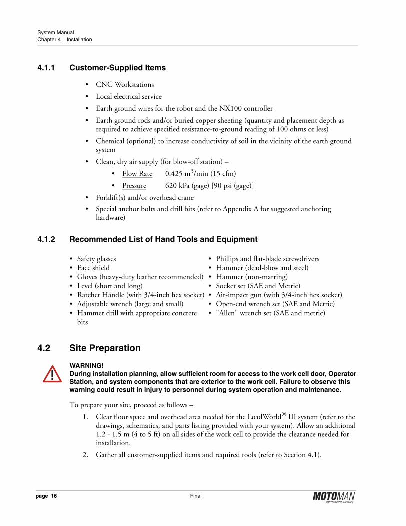
Figure 7 LoadWorld® III 20IA20 – Installation Dimensions and Component Locations (Plan View)
✍ Note: Your cell layout will vary from that shown based on purchased options and other process requirements. Refer to you system prints for your specific cell configuration.
Figure 8 LoadWorld® III 20IA20 – Installation Dimensions and Component Locations (Elevation View)
OPTIONALGRIP
TABLE
OPTIONALGRIP
TABLE
2588
3190
4077
2395
page 18 Final
LoadWorld® III153770-1
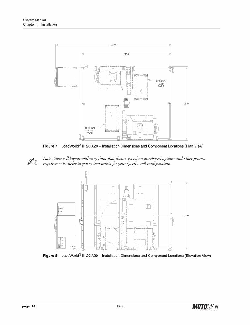
4.3 Removal of System Components from Shipping Skids
System components are attached to wooden shipping skids and/or wooden blocks at the factory, prior to shipment to the customer. The customer is responsible for removing the shipping skids and/or blocks and inspecting the components for shipping damage.
✍ Note: If you notice any equipment damage, notify your shipping contractor as soon as possible.
1. Unbolt each component from its shipping skid or block using a ¾-inch socket (see Figure 9).
2. Use forklift(s) or overhead crane to lift each component away from its shipping skid.
3. Discard or recycle the shipping skids and other shipping materials.
Figure 9 Removal of Typical Shipping Bolt
4.4 Component Installation
To make sure the LoadWorld® III work cell is complete and to verify the correct amount of floor space for the installation, Motoman recommends that all system components be set in place prior to anchoring the components to the foundation. Refer to the system drawings supplied with your LoadWorld® III system, to correctly place system components.
4.4.1 Place System Components
Before permanently anchoring the cell components to the floor, set all pieces in place in the following order:
1. Place CNC workstations into position according to your system prints.
2. Place the robot in the specified location relative to the CNC workstations.
3. Interconnect the safety fence panels and place them in position so that they enclose the work cell (see Figure 7 and refer to fence installation documentation that is supplied with the LoadWorld® III system).
4. Ensure that the final placement of the assembled safety fence conforms to the placement dimensions shown in Figure 7.
TYPICAL SYSTEMCOMPONENT
LEVELING BOLT
SHIPPING BOLT
NOTE: Wooden shipping skid not shown
Final page 19

System Manual Chapter 4 Installation
5. Install the work cell sliding door to the safety fencing (refer to Figure 7 and the safety fencing documentation that is supplied with the LoadWorld® III system).
6. Place the NX100 controller (see Figure 7 and your system drawings for the correct location for these components).
✍ Note: Do not place the NX100 controller any closer than 152.4 mm (6 in) to the work cell safety fencing.
4.4.2 Level and Anchor System Components
When all LoadWorld® III system components are in correct position, proceed with the following steps in this section to level system components (if required) and anchor them to the foundation (refer to Appendix A for foundation and anchoring suggestions).
!CAUTION!Be absolutely certain of the correct location for each LOADWORLD® III system component before anchoring it to the foundation.
!WARNING!Wear protective eye wear during the anchoring process. Failure to observe this warning could result in eye injury for the installation technician.
1. If required, level a system component by adjusting levelling bolts (see Figure 10).
2. After positioning and levelling (if required) a system component, insert a drill bit through the center of each levelling bolt and drill a hole into the foundation to accept an anchor bolt (refer to Appendix A for foundation and anchoring suggestions)
3. Use compressed air to remove all concrete dust from each drilled hole.
4. Anchor the system component to the foundation with suitable anchor bolts (refer to Appendix A for foundation and anchoring suggestions).
5. Repeat all steps in this section for each system component that requires anchoring.
Figure 10 Typical Levelling Bolt
LEVELINGBOLT
TYPICAL SYSTEMCOMPONENT
page 20 Final

LoadWorld® III153770-1
4.5 Cable Connections
After the LoadWorld® III system components and peripherals are anchored in their correct locations, locate the interconnect cables for the system components and route them according to the system drawings and schematics included in the LoadWorld® III system documentation package. All cables and connectors are labelled to ensure correct connection to the mating connectors on the applicable system component.
✍ Note: A small gap of approximately 100 mm (4 in) exists between the bottom of the work cell safety fence and the floor. This gap provides a passage for cables that link components outside the work cell with those that are inside the work cell.
4.5.1 Connection to Earth Ground
!WARNING!Do not use the LoadWorld® III system unless specified components are connected to a low-resistance earth ground. Do not connect the earth ground wire with the wires for the other high voltage equipment. The low-resistance earth ground must be a “dedicated” ground that is a direct connection between a component and the earth ground point. Operator injury or death, as well as equipment damage, can result from an inadequate or defective earth ground system.
The IA-Series robot and NX100 controller must be connected to a low-resistance earth ground. If a ground stake is used, it should be driven at least 2.43 m (8 ft) into the soil. The soil surrounding the driven ground stake should be treated with a chemical that increases the soil conductivity in the vicinity of the driven ground stake. The earth ground may require more than a single driven ground rod, depending on soil conditions. Often, multiple ground rods (bonded together) or even a bonded network of buried copper sheeting (plus conduction-enhancing chemicals) may be required, depending on local soil condition. In any event, the “low-resistance earth ground” must indicate a resistance of 100 ohms or less (when measured directly between grounded equipment and the earth ground system). Specialized electronic measuring equipment is usually required to get an accurate “resistance-to-ground” reading. Consult a specialist in this field, if required.
✍ Note: The customer shall supply all wires associated with the earth ground. The customer is responsible for establishing the correct gauge of all wires associated with the earth ground and maintaining an adequate earth ground (measured resistance of 100 ohms or less).
Connect the robot and NX100 controller to the earth ground as follows –
1. Connect one end of an earth ground wire to the lug marked EARTH GROUND on the connector panel of robot. Connect the other end of the earth ground wire to the low-resistance earth ground. See Figure 1 for location of robot.
2. Connect one end of an earth ground wire to the COMMON GROUND BUS BAR located inside NX100 controller (see Figure 2). Connect the other end of the earth ground wire to the low-resistance earth ground.
Final page 21

System Manual Chapter 4 Installation
4.5.2 Connection to Local Electrical Service
!WARNING!Local electrical service connection to the LoadWorld® III system must be performed by a qualified, licensed electrician. Electrical and grounding connections must comply with the National Electrical Code (NEC), as well as all local electrical codes.
✍ Note: The LoadWorld® III system is configured for 3-phase 460/480V AC primary power. For additional information, refer to the electrical drawings and schematics that are included with your system documentation package (refer to Section 1.3).
After all of the system components have been properly installed and interconnected, connect local electrical service to the NX100 controller (refer to Section 4.5.2.1).
4.5.2.1 NX100 Controller
For detailed electrical service interconnect procedures for the NX100 controller assembly, refer to the NX100 Controller Manual and LoadWorld® III system drawings / schematics that are included with your system documentation package (refer to Section 1.3).
4.6 Safety / Operation Check
Before installing the tooling and fixtures for your application, take a few minutes to perform the following safety/operation check –
1. Ensure that the shipping bracket is removed from the robot (refer to Section 4.5).
2. Ensure correct alignment and operation of the safety light curtain system (refer to safety light curtain documentation that is included with the LoadWorld® III system).
3. Check the security and integrity of all cable connections.4. Ensure that the work cell sliding access door is closed and that the door interlock is
engaged.5. Verify that local electrical service complies with the power requirements for your
LoadWorld® III system.6. Verify that local electrical service is correctly wired into the NX100 controller.
!CAUTION!The LOADWORLD® III system is now ready for power-up. Qualified, trained personnel, who are familiar with this system, should perform the power-up sequence.
7. Rotate the POWER ON-OFF Switch on NX100 controller to ON (see Figure 2).
✍ Note: An electrical service disconnect box for the NX100 controller assembly shall be supplied (if desired) by the customer. It is not part of the LoadWorld® III system shipment.
!WARNING!Before operating the robots, verify that each E-Stop push button disables servo power when activated (pushed in). Each E-Stop push button must immediately stop robot and positioner movement when activated (pushed in).
page 22 Final

LoadWorld® III153770-1
8. Check for correct operation of all E-Stop push buttons (refer to Section 3.4.2).9. Check for correct operation of the system HOLD button on the Programming Pendant.
10. Check for correct action of the work cell access door safety interlock.11. Remove power from the LoadWorld® III system after completion of the
safety / operation check.
Final page 23

System Manual Chapter 4 Installation
Notes
page 24 Final
LoadWorld® III153770-1
Chapter 5
Operation
!CAUTION!The customer is responsible for providing trained operators to run the equipment. The customer is also responsible for making sure that the equipment is operated in accordance with the ANSI/RIA R15.06-1999 Robot Safety standard, as well as any other local or state standards.
This chapter provides a brief overview of the operating procedures and precautions for your LoadWorld® III system. For more detailed operating information, refer to specific component manuals that are part of the LoadWorld® III system documentation package (refer to Section 1.3).
The operator loads the part holding stations with parts to be machined. The IA20 robot then processes the parts at the CNC workstations. When the machining process is complete, the robot returns the finished parts to the part holding stations and returns to a Home (Safe) position allowing the operator to remove finished parts and load new parts to be processed.
5.1 Programming
The operation of the LoadWorld® III system is programming dependent. The following operating instructions are based on one possible configuration for this system. Your system configuration and job structure may differ slightly from that presented here; however, basic operation will be the same. For additional programming procedures and information, refer to the NX100 controller documentation that is included with your LoadWorld® III system documentation package (refer to Section 1.3).
Any changes made to your system configuration or job structure will alter the operation of the system. Motoman recommends that you DO NOT modify the original jobs and system configuration of your LoadWorld® III system. If you determine a need to modify the original jobs and system configuration, make any modifications to a copy of the original. Keep the original as a backup. Do not modify the original. Modifications must be performed by trained and experienced personnel who are familiar with the operation of the LoadWorld® III system. If you have questions concerning the configuration of your system, please contact Motoman 24 hour Customer Support (refer to Section 1.4).
Final page 25

System Manual Chapter 5 Operation
5.2 Daily Operation
The procedures below represent the typical operating sequence from power up to shutdown. Your basic operating procedures may vary depending on your situation.
• Perform start-up procedures (refer to Section 5.2.1).
• Move robot to Home position (refer to Section 5.2.2).
• Select Master Job (refer to Section 5.2.3).
• Perform operation cycle (refer to Section 5.2.4)
• Perform shutdown procedures (refer to Section 5.2.5)
5.2.1 Start-Up
To start up the LoadWorld® III work cell from a power-off condition, proceed as follows –
✍ Note: Electrical service disconnect boxes shall be supplied (if desired) by the customer. They are not part of the LoadWorld® III system shipment.
1. Rotate the NX100 controller POWER ON-OFF switch to ON (see Figure 2).
2. Set POWER ON for each CNC workstation to ON.
3. Make sure each work cell access door is closed and the door safety interlock engaged.
4. Make sure all E-Stop push buttons are released. E-Stop push buttons are installed at the following locations –
• Programming Pendant
• NX100
5. Select TEACH mode on the Programming Pendant.
6. Place robot in Home position (refer to Section 5.2.2).
5.2.2 Robot Home Position
To move the robots to the Home position –
1. Select TEACH mode on the Programming Pendant.
2. Select MAIN MENU on Programming Pendant touch screen.
3. Select JOB on Programming Pendant touch screen.
4. Select SELECT JOB on Programming Pendant touch screen (a job list appears).
5. Use the navigation cursor key to move the cursor to R1 SAFE job and press SELECT (the job appears on the display screen).
6. Turn servo power ON by pressing SERVO ON and holding in the ENABLE switch.
7. Use the FWD button on Programming Pendant to jog robot (R1) to Home position.
page 26 Final

LoadWorld® III153770-1
5.2.3 Master Job
With the system powered up and in TEACH mode, call up the Master Job –
1. Select JOB on Programming Pendant touch screen.
2. Select CTRL MASTER on Programming Pendant touch screen. Press SELECT twice to activate the Master Job.
3. Select PLAY mode on Programming Pendant and press the PLAY ENABLE button on the NX100 controller door (job playback operation is enabled). See Figure 2 for location of the PLAY ENABLE button on the controller.
4. Press SERVO ON button on the Programming Pendant.
5. Press START button on Programming Pendant (the Master Job cycles).
The LoadWorld® III work cell is now ready for operation.
5.2.4 Operation Cycle
The following is the typical sequence of operation for the LoadWorld® III work cell after start-up:
1. Operator loads the fixture (on part holding stantion) with parts to be machined.
2. Operator steps out of the cell, and moves to the NX100 controller.
3. Operator presses the START button on Programming Pendant. The robot then begin to process the parts at a CNC workstation.
4. While the robot is processing a part, the operator prepares the next group of parts to be machined.
5. When the robot finishes processing a part, it loads the finished part(s) onto the part holding stantion and returns to Home position.
6. Operator unloads completed parts and loads new parts to be machined.
5.2.5 Shutdown
Use the following procedure to perform a normal shut down of the LoadWorld® III system:
1. Make sure the robot is in Home position.
2. Turn off system servo power by pressing the E-Stop button on operator station or programming pendant.
3. Select TEACH mode on the programming pendant.
4. Rotate NX100 controller POWER ON-OFF switch to OFF (see Figure 2).
5. Remove power from the CNC workstations.
The LoadWorld® III system is now shut down.
Final page 27

System Manual Chapter 5 Operation
5.3 System Recovery
When a system error or alarm occurs, you must clear the error or alarm to return the system to normal operation. The paragraphs below describe the different types of alarms and errors you may encounter, and how to clear them.
5.3.1 Alarms and Errors
Alarms and errors will stop the program. There are three levels –
• Error Messages
• Minor Alarms
• Major Alarms
For more detailed information on alarm and error recovery, refer to the NX100 controller and IA-Series robot documentation that is included with your LoadWorld® III documentation package (refer to Section 1.3).
5.3.1.1 Error Messages
Error messages are usually the result of simple, easily-cleared operation errors. The following is one example –
• Pressing the START button when the robot is not in PLAY mode
Clear errors of this type by pressing the CANCEL button on the programming pendant.
5.3.1.2 Minor Alarms
Minor alarms usually involve programming errors. Clear alarms of this type by pressing the CANCEL button on the programming pendant.
5.3.1.3 Major Alarms
Clear alarms of this type by cycling the NX100 controller in accordance with the following steps:
1. Rotate the NX100 POWER ON-OFF switch to OFF (see Figure 2).
2. Allow the NX100 POWER ON-OFF switch to remain in the OFF position for approximately 10 seconds.
3. Rotate the NX100 POWER ON-OFF switch back to ON.
page 28 Final
LoadWorld® III153770-1
5.3.2 E-Stop Recovery
An E-Stop (emergency stop) condition is triggered by any of the following conditions –
• An E-Stop push button switch is activated
• The work cell access door is opened while the robot is not in TEACH mode
• A collision triggers a shock sensor output
If an E-Stop condition is triggered, restart the LoadWorld® III system as follows:
!CAUTION!If an E-Stop condition occurs while the positioner is sweeping, the positioner will complete the sweep when the LoadWorld® III system is restarted.
1. Press the SERVO ON button on the Programming Pendant.
2. Select REMOTE mode on the Programming Pendant MODE SELECT SWITCH to transfer control of the system to the Operator Station.
3. Press the green START button on the Operator Station.
The LoadWorld® III system is now ready to continue operation.
5.3.3 Brake Release
The robot braking system is designed to protect the robots and other system components from damage in the event of a system / robot failure or loss of drive power. If a system / robot failure or loss of drive power occurs, you must release the brakes on the affected robot in order to move it.
To release the brakes, proceed as follows:
!WARNING!Always support the robot axis to be released BEFORE you release it. Without adequate robot axis support, brake release could cause personal injury or machine damage.
1. On the Programming Pendant, select TEACH mode and turn servo power OFF.
2. Select ROBOT on the pendant display (touch) screen.
3. Select the BRAKE RELEASE option.
4. Use the CURSOR key to select desired robot axis for release.
5. Press and hold the pendant ENABLE switch in its middle position (see Figure 3 and Figure 4), while pressing the INTERLOCK key and the SELECT key.
6. The brake for the selected axis releases.
Final page 29

System Manual Chapter 5 Operation
NOTES
page 30 Final
LoadWorld® III153770-1
Chapter 6
Maintenance
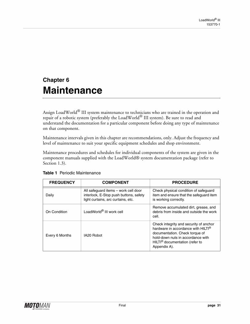
Assign LoadWorld® III system maintenance to technicians who are trained in the operation and repair of a robotic system (preferably the LoadWorld® III system). Be sure to read and understand the documentation for a particular component before doing any type of maintenance on that component.
Maintenance intervals given in this chapter are recommendations, only. Adjust the frequency and level of maintenance to suit your specific equipment schedules and shop environment.
Maintenance procedures and schedules for individual components of the system are given in the component manuals supplied with the LoadWorld® system documentation package (refer to Section 1.3).
Table 1 Periodic Maintenance
FREQUENCY COMPONENT PROCEDURE
DailyAll safeguard items – work cell door interlock, E-Stop push buttons, safety light curtains, arc curtains, etc.
Check physical condition of safeguard item and ensure that the safeguard item is working correctly.
On Condition LoadWorld® III work cellRemove accumulated dirt, grease, and debris from inside and outside the work cell.
Every 6 Months IA20 Robot
Check integrity and security of anchor hardware in accordance with HILTI® documentation. Check torque of hold-down nuts in accordance with HILTI® documentation (refer to Appendix A).
Final page 31

System Manual Chapter 6 Maintenance
NOTES
page 32 Final

LoadWorld® III153770-1
Appendix A
Anchoring
The customer shall determine all anchoring and foundation requirements, and supply the appropriate anchoring hardware and foundation for a particular system installation. Table A.1 gives anchoring and foundation suggestions.
Table A.1 Suggested Anchor, Floor Plate, and Foundation Specifications
SYSTEM EQUIPMENTMINIMUM HILTI®
ANCHOR ROD DIA / TYPEMINIMUM FLOOR PLATE MINIMUM FOUNDATION
ROBOTSHP3JC, HP3, HP3C, HP3CL, HP3XF, HP5, HP5C
1/2" HVA Chemical Anchor(Note 3) (Note 5) (Note 6)
380 mm (15 in) Length380 mm (15 in) Width19 mm (0.7 in) Thick
381 mm (15.0 in) Length381 mm (15.0 in) Width76 mm (3.0 in) Thick4000 psi Reinforced Concrete
ROBOTSUP6, UP20 UP20-6, EA1400, EA1900
5/8" HVA Chemical Anchor(Note 3) (Note 5) (Note 6)
600 mm (24 in) Length600 mm (24 in) Width38.1 mm (1.5 in) Thick
762 mm (30.0 in) Length762 mm (30.0 in) Width178 mm (7.0 in) Thick4000 psi Reinforced Concrete
ROBOTSHP6, HP6S, HP6R, HP20, HP20-6, EA1400N, EA1900N, DX1350N
5/8" HVA Chemical Anchor(Note 3) (Note 5) (Note 6)
600 mm (24 in) Length600 mm (24 in) Width38.1 mm (1.5 in) Thick
762 mm (30.0 in) Length762 mm (30.0 in) Width178 mm (7.0 in) Thick4000 psi Reinforced Concrete
ROBOTSUP20M, UP50SP80(Note 2)
7/8" HVA Chemical Anchor(Note 3) (Note 5)(Note 6)
900 mm (35.4 in) Length900 mm (35.4 in) Width50.8 mm (2.0 in) Thick
1524 mm(60.0 in) Length1524 mm(60.0 in) Width229 mm (9.0 in) Thick4000 psi Reinforced Concrete
ROBOTSHP50, HP50-20, HP50-35, EPL80(Note 2)
7/8" HVA Chemical Anchor(Note 3) (Note 5)(Note 6)
900 mm (35.4 in) Length900 mm (35.4 in) Width50.8 mm (2.0 in) Thick
1524 mm(60.0 in) Length1524 mm(60.0 in) Width229 mm (9.0 in) Thick4000 psi Reinforced Concrete
ROBOTSUP120,UP130 UP165,SP100 SP160,SP250 SP400(Note 2)
7/8" HVA Chemical Anchor(Note 3) (Note 5) (Note 6)
1200 mm(47.2 in) Length1200 mm(47.2 in) Width50.8 mm (2.0 in) Thick
1828 mm(72.0 in) Length1828 mm(72.0 in) Width229 mm (9.0 in) Thick4000 psi Reinforced Concrete
ROBOTSHP165, HP165N-100, HP165R, ES165RN, ES165N, ES165N-100, EPL100, EPL160(Note 2)
7/8" HVA Chemical Anchor(Note 3) (Note 5) (Note 6)
1200 mm(47.2 in) Length1200 mm(47.2 in) Width50.8 mm (2.0 in) Thick
1828 mm(72.0 in) Length1828 mm(72.0 in) Width229 mm (9.0 in) Thick4000 psi Reinforced Concrete
Final page 33

System Manual Appendix A Anchoring
ROBOTSUP200
7/8" HVA Chemical Anchor (Note 3) (Note 5) (Note 6)
1200 mm(47.2 in) Length1200 mm(47.2 in) Width50.8 mm (2.0 in) Thick
1828 mm(72.0 in) Length1828 mm(72.0 in) Width229 mm (9.0 in) Thick4000 psi Reinforced Concrete
ROBOTSHP200, ES200N, HP200T, HP200RN, ES200RN, EPL300(Note 2)
7/8" HVA Chemical Anchor (Note 3) (Note 5) (Note 6)
1200 mm(47.2 in) Length1200 mm(47.2 in) Width50.8 mm (2.0 in) Thick
1828 mm(72.0 in) Length1828 mm(72.0 in) Width229 mm (9.0 in) Thick4000 psi Reinforced Concrete
ROBOTSUP350, UP500, SK300X
7/8" HVA Chemical Anchor (Note 3) (Note 5) (Note 6)
1500 mm(59.1 in) Length1500 mm(59.1 in) Width50.8 mm (2.0 in) Thick
1828 mm(72.0 in) Length1828 mm(72.0 in) Width229 mm (9.0 in) Thick4000 psi Reinforced Concrete
ROBOTSHP350, HP350-200, HP500, HP600, EPL450, EPL500(Note 2)
7/8" HVA Chemical Anchor (Note 3) (Note 5) (Note 6)
1500 mm(59.1 in) Length1500 mm(59.1 in) Width50.8 mm (2.0 in) Thick
1828 mm(72.0 in) Length1828 mm(72.0 in) Width229 mm (9.0 in) Thick4000 psi Reinforced Concrete
POSITIONERRotary Turntable Type
5/8" HVA Chemical Anchor (Note 3)(Note 6)
Not Applicable Refer to Applicable Positioner Manual
POSITIONER“Ferris wheel” type with headstock and tailstock (HS/TS)
7/8" HVA Chemical Anchor (Note 3)(Note 6)
Not Applicable Refer to Applicable Positioner Manual
PERIPHERAL EQUIPMENT
1/2" Kwik Bolt II Expansion Anchor (Note 4) (Note 6)
Not Applicable
3" min thickness or 1.3 Embedment Depth (whichever is larger), 4000 psi Reinforced Concrete
WORK CELL FENCE POSTS
3/8" Kwik Bolt II Expansion Anchor(Note 4) (Note 6)
Not Applicable
3" min thickness or 1.3 Embedment Depth (whichever is larger), 4000 psi Reinforced Concrete
Notes –
(1) Minimum robot lagging requirements are based on Maximum Repulsion Forces and Hilti® Anchor Design Program (v3.3b).
(2) SP and EPL series robots require base plates and/or risers to be level to ± 2°. Grout if necessary.
(3) Reference source: Hilti® Product Technical Guide (section 4.2.1) for hardware specifications or equivalent.
(4) Reference source: Hilti® Product Technical Guide (section 4.3.3) for hardware specifications or equivalent.
(5) Cast-in anchors are specified in some robot manuals. The Hilti® HVA Chemical Anchors listed in this table can be substituted for the cast-in anchors.
(6) Refer to Hilti® Product Technical Guide for suggestions on the correct size and type of drill bit to use with each anchor type.
Contact Information –
1-800-879-8000 (USA) http://us.hilti.com1-800-363-4458 (CAN) http://ca.hilti.com
Table A.1 Suggested Anchor, Floor Plate, and Foundation Specifications
SYSTEM EQUIPMENTMINIMUM HILTI®
ANCHOR ROD DIA / TYPEMINIMUM FLOOR PLATE MINIMUM FOUNDATION
page 34 Final

LoadWorld® III153770-1
Appendix B
Gripper Assemblies
The LoadWorld® III gripper assemblies provide a complete end-of-arm tooling solution. Each gripper assembly includes upper arm I/O cables, Parker Moduflex, valve modules, airlines and fittings. Three different designs are available to accomodate your application requirements.
153627-1 90D (90-Degree)The 90D provides two PZN three jaw grippers mounted on a Schunk compact swivel head unit.
153627-2 BTB (Back-to-Back)The BTB provides two PZN three jaw grippers mounted back-to-back on the centerline of the robot T-Axis.
153627-3 2I (Inline)The 2I provides two PZN three jaw grippers mounted inline on a plate that is in turn mounted to the robot T-Axis.
B.1 Illustrated Parts List
The Illustrated Parts List identifies, describes, an illustrates detail parts of the main assemblies for the LoadWorld® III gripper assemblies manufactured by Motoman.
This list provides parts identification and descriptive information for use in provisioning, requesting, purchasing, storing, and issuing spare parts.
B.1.1 Explanation of Parts List
Contents
The parts list contains a breakdown of the equipment into detail parts. All parts of the equipment are listed except the following:
1. Standard hardware items (attaching parts) such as nuts, screws, washers, etc., which are available commercially.
2. Bulk items such as wire, cable, sleeving, tubing, etc., which are also commerically available.
3. Permanently attached parts which lose their identity by being welded, soldered, riveted, etc., to other parts, or assemblies.
Final page 35

System Manual Appendix B Gripper Assemblies
Parts List Form
This form is divided into four columns as follows:1. “Figure - Item Number” Column
Lists the figure number of the illustration applicable to a particular parts list and also identifies each part in the list by an item number. These item numbers also appear on the illustration. Each time number on the illustration is connected to the part to which it pertains by a leader line and arrow. Thus, the figure and item numbering system ties the parts list to the illustration and vice versa.
2. “Motoman Part Number Column”All part numbers appearing in this column are Motoman part numbers.
3. “Description” ColumnThe item nomenclature appears in this column.
4. “QTY” ColumnIndicates the quantity of parts required for an assembly or sub-assembly in which the part appears. This column does not necessarily reflect the total used in the complete end item.
B.2 Parts List
B.2.2 Explanation of Parts List Arrangement
The parts list is arranged so that the illustration will appear on left-hand page and the applicable parts list will appear on the opposite right-hang page. Unless the list is unusually long, the user will be able to look at the illustration and read the parts list without turning a page.
B.2.3 Symbols and Abbreviations
The following is a list of symbols and abbreviations used in the parts list.amp – ampere
AC – alternating current
cyl – cylinder
DC – direct current
fig – figure
ID – Inside diameter
in. – inch
m – meter
mm – millimeter
No. – number
psi – pounds per square inch
page 36 Final
LoadWorld® III153770-1
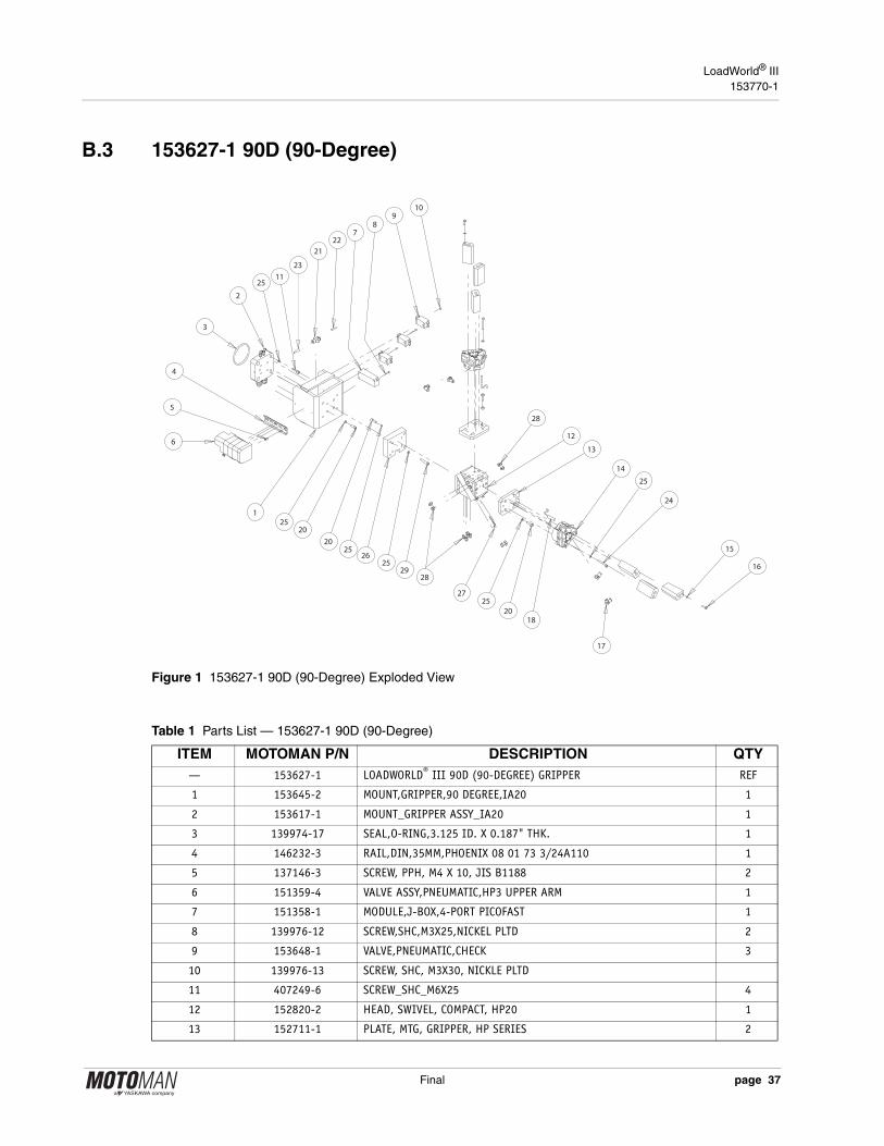
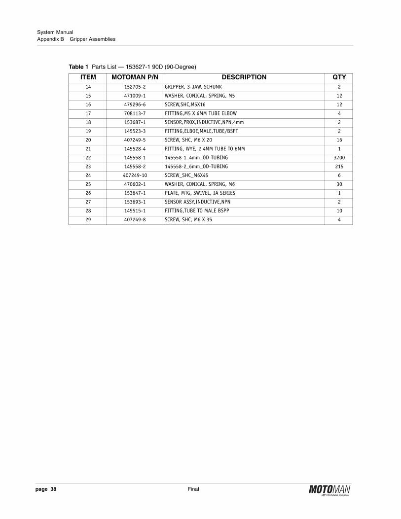
B.3 153627-1 90D (90-Degree)
Figure 1 153627-1 90D (90-Degree) Exploded View
Table 1 Parts List — 153627-1 90D (90-Degree)
ITEM MOTOMAN P/N DESCRIPTION QTY— 153627-1 LOADWORLD® III 90D (90-DEGREE) GRIPPER REF
1 153645-2 MOUNT,GRIPPER,90 DEGREE,IA20 1
2 153617-1 MOUNT_GRIPPER ASSY_IA20 1
3 139974-17 SEAL,O-RING,3.125 ID. X 0.187" THK. 1
4 146232-3 RAIL,DIN,35MM,PHOENIX 08 01 73 3/24A110 1
5 137146-3 SCREW, PPH, M4 X 10, JIS B1188 2
6 151359-4 VALVE ASSY,PNEUMATIC,HP3 UPPER ARM 1
7 151358-1 MODULE,J-BOX,4-PORT PICOFAST 1
8 139976-12 SCREW,SHC,M3X25,NICKEL PLTD 2
9 153648-1 VALVE,PNEUMATIC,CHECK 3
10 139976-13 SCREW, SHC, M3X30, NICKLE PLTD
11 407249-6 SCREW_SHC_M6X25 4
12 152820-2 HEAD, SWIVEL, COMPACT, HP20 1
13 152711-1 PLATE, MTG, GRIPPER, HP SERIES 2
5
8
10
24
20
11
29
25
16
17
9
3
4
6
2
1
26
27
12
18
7
14
13
15
25
25
2520
2025
25
2221
23
28
28
Final page 37
System Manual Appendix B Gripper Assemblies
14 152705-2 GRIPPER, 3-JAW, SCHUNK 2
15 471009-1 WASHER, CONICAL, SPRING, M5 12
16 479296-6 SCREW,SHC,M5X16 12
17 708113-7 FITTING,M5 X 6MM TUBE ELBOW 4
18 153687-1 SENSOR,PROX,INDUCTIVE,NPN,4mm 2
19 145523-3 FITTING,ELBOE,MALE,TUBE/BSPT 2
20 407249-5 SCREW, SHC, M6 X 20 16
21 145528-4 FITTING, WYE, 2 4MM TUBE TO 6MM 1
22 145558-1 145558-1_4mm_OD-TUBING 3700
23 145558-2 145558-2_6mm_OD-TUBING 215
24 407249-10 SCREW_SHC_M6X45 6
25 470602-1 WASHER, CONICAL, SPRING, M6 30
26 153647-1 PLATE, MTG, SWIVEL, IA SERIES 1
27 153693-1 SENSOR ASSY,INDUCTIVE,NPN 2
28 145515-1 FITTING,TUBE TO MALE BSPP 10
29 407249-8 SCREW, SHC, M6 X 35 4
Table 1 Parts List — 153627-1 90D (90-Degree)
ITEM MOTOMAN P/N DESCRIPTION QTY
page 38 Final
LoadWorld® III153770-1
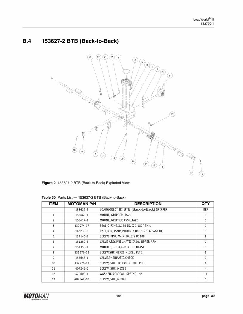
B.4 153627-2 BTB (Back-to-Back)
Figure 2 153627-2 BTB (Back-to-Back) Exploded View
Table 30 Parts List — 153627-2 BTB (Back-to-Back)
ITEM MOTOMAN P/N DESCRIPTION QTY— 153627-2 LOADWORLD® III BTB (Back-to-Back) GRIPPER REF
1 153645-1 MOUNT, GRIPPER, IA20 1
2 153617-1 MOUNT_GRIPPER ASSY_IA20 1
3 139974-17 SEAL,O-RING,3.125 ID. X 0.187" THK. 1
4 146232-3 RAIL,DIN,35MM,PHOENIX 08 01 73 3/24A110 1
5 137146-3 SCREW, PPH, M4 X 10, JIS B1188 2
6 151359-3 VALVE ASSY,PNEUMATIC,IA20, UPPER ARM 1
7 151358-1 MODULE,J-BOX,4-PORT PICOFAST 1
8 139976-12 SCREW,SHC,M3X25,NICKEL PLTD 2
9 153648-1 VALVE,PNEUMATIC,CHECK 2
10 139976-13 SCREW, SHC, M3X30, NICKLE PLTD 4
11 407249-6 SCREW_SHC_M6X25 4
12 470602-1 WASHER, CONICAL, SPRING, M6 14
13 407249-10 SCREW_SHC_M6X45 6
5
8
10
1312
1516
17
9
3
4
6
2
1
18
7
14
17
2012
1211
232122
Final page 39

System Manual Appendix B Gripper Assemblies
14 152705-2 GRIPPER, 3-JAW, SCHUNK 2
15 471009-1 WASHER, CONICAL, SPRING, M5 12
16 479296-6 SCREW,SHC,M5X16 12
17 708113-7 FITTING,M5 X 6MM TUBE ELBOW 4
18 153687-1 SENSOR,PROX,INDUCTIVE,NPN,4mm 2
19 145523-3 FITTING,ELBOE,MALE,TUBE/BSPT 2
20 407249-5 SCREW, SHC, M6 X 20 4
21 145528-4 FITTING, WYE, 2 4MM TUBE TO 6MM 1
22 145558-1 145558-1_4mm_OD-TUBING 3200
23 145558-2 145558-2_6mm_OD-TUBING 215
Table 30 Parts List — 153627-2 BTB (Back-to-Back)
ITEM MOTOMAN P/N DESCRIPTION QTY
page 40 Final
LoadWorld® III153770-1
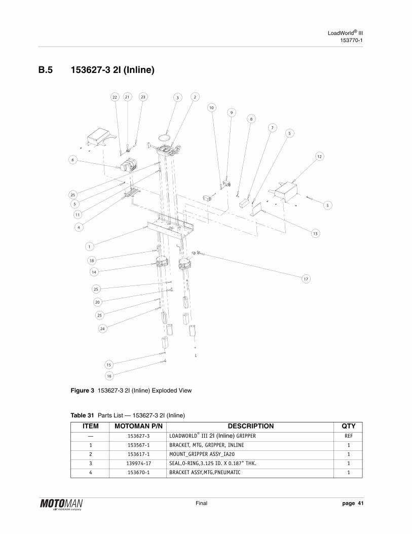
B.5 153627-3 2I (Inline)
Figure 3 153627-3 2I (Inline) Exploded View
5
10
8
24
20
11
25
15
9
321
6
2
13
4
18
7
14
1
25
16
5
25
17
2322
5
12
Table 31 Parts List — 153627-3 2I (Inline)
ITEM MOTOMAN P/N DESCRIPTION QTY— 153627-3 LOADWORLD® III 2I (Inline) GRIPPER REF
1 153567-1 BRACKET, MTG, GRIPPER, INLINE 1
2 153617-1 MOUNT_GRIPPER ASSY_IA20 1
3 139974-17 SEAL,O-RING,3.125 ID. X 0.187" THK. 1
4 153670-1 BRACKET ASSY,MTG,PNEUMATIC 1
Final page 41

System Manual Appendix B Gripper Assemblies
5 137146-3 SCREW, PPH, M4 X 10, JIS B1188 18
6 151359-3 VALVE ASSY,PNEUMATIC,IA20, UPPER ARM 1
7 151358-1 MODULE,J-BOX,4-PORT PICOFAST 1
8 140349-7 SCREW,BHSC,M3x0.6 X 20, SST 2
9 153648-1 VALVE,PNEUMATIC,CHECK 2
10 139976-13 SCREW, SHC, M3X30, NICKLE PLTD 4
11 407249-6 SCREW_SHC_M6X25 4
12 153566-1 COVER,VALVE,GRIPPER,IA20 2
13 153639-1 BRACKET,TURCK BLOCK MOUNTING 1
14 152705-2 GRIPPER, 3-JAW, SCHUNK 2
15 471009-1 WASHER, CONICAL, SPRING, M5 12
16 479296-6 SCREW,SHC,M5X16 12
17 708113-7 FITTING,M5 X 6MM TUBE ELBOW 4
18 153687-1 SENSOR,PROX,INDUCTIVE,NPN,4mm 2
19 145523-3 FITTING,ELBOE,MALE,TUBE/BSPT 2
20 407249-5 SCREW, SHC, M6 X 20 4
21 145528-4 FITTING, WYE, 2 4MM TUBE TO 6MM 1
22 145558-1 145558-1_4mm_OD-TUBING 3000
23 145558-2 145558-2_6mm_OD-TUBING 215
24 407249-10 SCREW_SHC_M6X45 6
25 470602-1 WASHER, CONICAL, SPRING, M6 14
Table 31 Parts List — 153627-3 2I (Inline)
ITEM MOTOMAN P/N DESCRIPTION QTY
page 42 Final
LoadWorld® III153770-1
Final
Index
AAlarms 28BBacking-up original jobs and sys config 25Brake Release 29CCable Interconnects 21Components 3Customer Service 4Customer-Supplied Items 16DDaily Operation 26Documentation 4EEarth Ground, Importanct 21Emergency Stops (E-STOPS) 12ENABLE Switch, Programming Pendant 13Equipment Description 9GGeneral Safeguarding Tips 6IInstallation 15Installation and qualified personnel 15Installation Safety 7Interlocked Workcell Doors 13Introduction 1LLayout 3Low-Resistance Earth Ground 21MMaster Job 27Mechanical Safety Devices 7
Motoman Advanced Robot Motion® (ARM) con-trol algorithms. 9NNX100 Controller, description 9OOperation 25Optional Equipment 3Overview 2PPreventive Maintenance 31Programming Pendant, NX100 10, 11Programming the LoadWorld®III 25Programming, Operation, and Maintenance Safe-ty 8RRecommended Hand Tools and Equip. 16Required Installation Materials 15Robot Description 9Robot Home Position 26SSafety 5Safety / Operation Check 22Safety Equipment 3Safety Features 12Safety Fencing 12Site Preparation 16Standard Conventions 6System Layout 3System Overview 2System Recovery 28System Shutdown 27System Start-Up 26


![[Review of NX100 + 20-50mm lens] Performance of the NX100](https://img.dokumen.tips/doc/110x75/568bef531a28ab89338bc1ae/review-of-nx100-20-50mm-lens-performance-of-the-nx100-56e22b1aa4607.jpg)