Embed Size (px)
Citation preview

NEW INTEGRATED KNOWLEDGE BASED APPROACHES TO THE PROTECTION OF CULTURAL HERITAGE FROM EARTHQUAKE-INDUCED RISK
NIKER Grant Agreement n°
244123
Deliverable 10.2
Guidelines for assessment and improvement
of connections in buildings for end-users
Due date: December 2012
Submission date: December 2012
Issued by: ITAM
WORKPACKAGE 10: Guidelines for end-users
Leader: ITAM
PROJECT N°: 244123
ACRONYM: NIKER
TITLE: New integrated knowledge based approaches to the protection
of cultural heritage from earthquake-induced risk
COORDINATOR: Università di Padova (Italy)
START DATE: 01 January 2010 DURATION: 36 months
INSTRUMENT: Collaborative Project
Small or medium scale focused research project
THEME: Environment (including Climate Change)
Threaded bars and steel plates for vertical load (0.05/0.1 MPa)
Push & pull jacks fixed to strong wall for horizontal cyclic loading
Dissemination level: PU Rev: FIN

NEW INTEGRATED KNOWLEDGE BASED APPROACHES TO THE PROTECTION OF CULTURAL HERITAGE FROM EARTHQUAKE-INDUCED RISK
NIKER Grant Agreement n°
244123
Guidelines for end-users D10.2 i
INDEX
1 INTRODUCTION ..................................................................................................................... 2
1.1 DESCRIPTION AND OBJECTIVES OF THE WORK PACKAGE ...................................... 2
1.2 SUMMARY AND OBJECTIVES OF THE DELIVERABLE ................................................. 2
2 GENERAL REMARKS ............................................................................................................ 3
3 ASSESSMENT METHODS ..................................................................................................... 4
3.1 TEST OF SINGLE STRUCTURAL ELEMENT AND STRENGTHENING .......................... 5
3.1.1 Pull-Out Tests of Metallic Grouted Anchors from Brickwork Masonry ............................ 5
3.1.2 Pull-Out Tests of Anchor Pins from Earthen Materials ................................................... 8
3.1.3 Monotonic Pull-Out Test of Wall to Timber Frame Connections................................... 10
3.2 TEST OF WHOLE CONNECTION .................................................................................. 13
3.2.1 Cyclic Tests of T-Shape Walls ..................................................................................... 13
3.2.2 Cyclic Tests of Dovetail Halved Joints of Timber Roofs ............................................... 16
3.2.3 Monotonic Pull-Out Test of Timber Floor-Wall Connections ........................................ 19
3.3 TEST OF WHOLE STRUCTURE .................................................................................... 22
3.3.1 Shaking Table Tests of Timber-Laced Structure .......................................................... 22
4 IMPROVEMENT OF CONNECTIONS ................................................................................... 25
4.1 GROUTED METALLIC ANCHORS ENCASED IN FABRIC SOCK ................................. 29
4.2 ANCHOR PINS IN EARTHEN MATERIALS ................................................................... 33
4.3 METALLIC ANCHORS FOR WALL-TO-TIMBER FRAME CONNECTIONS ................... 37
4.4 METALLIC TIES AND STEEL ANGLES FOR WALL-TO-TIMBER FLOOR CONNECTIONS ........................................................................................................................ 42
4.5 STRENGTHENING OF CARPENTRY JOINTS ............................................................... 46
4.6 TIMBER LACING ............................................................................................................ 49
5 CONCLUSIONS .................................................................................................................... 51
6 REFERENCES ...................................................................................................................... 53

NEW INTEGRATED KNOWLEDGE BASED APPROACHES TO THE PROTECTION OF CULTURAL HERITAGE FROM EARTHQUAKE-INDUCED RISK
NIKER Grant Agreement n°
244123
Guidelines for end-users D10.2 2
1 INTRODUCTION
1.1 DESCRIPTION AND OBJECTIVES OF THE WORK PACKAGE
The exploitation of NIKER results covers both the use of exploitable knowledge and exploitable measures and products. Exploitable knowledge brings mainly non-commercial benefits for project participants and beyond the partnership (e.g. cultural heritage institutions, owners, RTD performers). By means of guidelines prepared in WP10, disseminated as described previously in other deliverables, the internal processes are improved for authorities in charge of CH maintenance. In such a way, cultural institutions and owners of cultural heritage can integrate the technologies and methodologies developed into their project and will be able to carry them out more effectively and more efficiently. The WP10 is subdivided into:
WP10.1: Guidelines for specific problems. These guidelines outline the main results obtained in WP3; WP4; WP5; WP6, WP7 and WP8 and are intended for designers and users of the technologies. Therefore, the entire work carried out into the project will be substantially simplified for the needs of the end-users and designers, by providing simple design rules, design formulations and design charts.
WP10.2: Guidelines for integrated methodologies. These guidelines summarize the main results obtained in WP7; WP8 and WP9 and are mainly oriented to designers or bodies responsible of the management and maintenance of the structures. They will contain the description of the new integrated knowledge based approaches for the protection the CH from earthquake-induced risks emerging from the project.
The main objectives of WP10 can be summarised as follow:
produce guidelines for the direct end-users of the developed technologies and tools (designers, architects, engineers, construction companies, bodies responsible of building maintenance, etc.), with practical information on design of interventions, execution of techniques, assessment tools, monitoring procedures;
produce guidelines for production and installation of advanced instrumented dissipative devices;
produce guidelines for owners and end-users of the developed technologies and tools (public entities, bodies responsible of building maintenance, authorities, etc.), with description of step-by-step integrated methodology for effective protection of cultural heritage;
spread awareness and establish reliable, effective, compatible, integrated approaches for the protection of cultural heritage from earthquake-induced risks.
The outcome of Workpackage 10 is presented in 5 deliverables, covering the aspects listed above.
1.2 SUMMARY AND OBJECTIVES OF THE DELIVERABLE
These guidelines (D10.2) provide information regarding the assessment procedures and the execution of optimum strengthening interventions of structural connections on the basis of experimental and numerical results achieved in WP6.
The deliverable deals with all those procedures necessary for a throughout assessment and improvement of performance of connections including: the experimental characterisation of the dynamic behaviour, the choice of materials and techniques for the intervention, the design and implementation of strengthening.

NEW INTEGRATED KNOWLEDGE BASED APPROACHES TO THE PROTECTION OF CULTURAL HERITAGE FROM EARTHQUAKE-INDUCED RISK
NIKER Grant Agreement n°
244123
Guidelines for end-users D10.2 3
2 GENERAL REMARKS
Connections are crucial in the seismic upgrade of historic buildings and a wide range of techniques and product are described in the scientific literature and used in current practice to ensure the enhancement of existing connections. Indeed, the global response of historic buildings is determined by the behaviour of single structural elements as well as by their mutual connections. However, in current practice, the assessment of the latter mainly relies on experience and qualitative parameters notwithstanding the fact that, in respect to engineered structures, heritage buildings require even more attention, especially when dealing with issues such as the compatibility between the chemical and mechanical properties of the strengthening system and the parent material. Indeed, many strengthening techniques, after an initial success and a strong commercial promotion, have proved to not perform at the required level and showed unexpected drawbacks, principally due to the excessive stiffness and scarce compatibility of the additional elements in respect to the original structure. Still, when correctly designed and implemented, strengthening systems can provide highly flexible applications and meet the expected requirements in terms of performance. More and more of these systems draw on traditional reinforcement techniques, and fully exploit the potential of innovative materials and of a deeper insight in the laws governing the dynamics of structures.
In order to achieve a correct design and implementation of these strengthening techniques, appropriate insight into the response of both the unreinforced and the strengthened connection is required. The pursuit of in-depth technical knowledge through experimental assessment is a well-established practice both in the scientific community and among the commercial producers. It is therefore surprising how testing of connections as such is rarely performed and very few codes of practice deal with this topic. In fact, strengthening products are generally tested at a local scale for repair and upgrade of single structural elements or at a global scale; in this latter case, complex systems of strengthening involving different techniques positioned at various locations are used. In the light of these considerations and of the need for homogeneous guidelines for the testing of strengthening for structural connections, Chapter 3 of this deliverable presents a set of procedures whereby the response of connections can be isolated from the global behaviour of the structure. This allows gaining a better insight into the performance of strengthening technologies and achieving a set of standards for the experimental assessment of new products in the controlled environment of laboratories.
Chapter 4 deals instead with that phase of a repair/upgrade intervention when the assessment of the connection has been completed and a strategy for the improvement has to be devised: guidance is given in regards to the implementation of a number of strengthening systems, their advantages and shortcomings and the factors that should be taken into account so as to perform an intervention that is both structurally effective and sympathetic to the original materials. Moreover, a list of design parameters is provided to the purpose of supporting the reader in the process of design of the strengthening elements.

NEW INTEGRATED KNOWLEDGE BASED APPROACHES TO THE PROTECTION OF CULTURAL HERITAGE FROM EARTHQUAKE-INDUCED RISK
NIKER Grant Agreement n°
244123
Guidelines for end-users D10.2 4
3 ASSESSMENT METHODS
The information reported in this chapter aims at tackling the lack of a systematic approach to the experimental assessment of unreinforced, reinforced or strengthened structural connections.
Indeed only a small number of experimental campaigns reported in the technical literature deal specifically with the strengthening of connections rather than with the upgrade of the whole structure at the global level. Additionally, the few publications focusing on the response of connections lack the necessary homogeneity and standardisation to allow for a direct comparison between different retrofit techniques. Moreover, quantitative data is extremely scarce in respect to the great variety of commercially available strengthening systems.
Drawing on these observations, a set of experimental procedures was developed within the framework of the NIKER projects. Testing procedures aim both to characterise connections in their unreinforced and strengthened set-up and to identify and quantify a set of meaningful performance parameters that can be used for the design and implementation of standard and innovative techniques. Accordingly, Chapter 3 describes the test procedures and set-ups, and lists measurements to be taken during tests so as to record values of the performance parameters. Chapter 4 summarises the advantages and disadvantages of each technique, the criteria for correct on-site installation and collates the formulae and references for the implementation of performance parameter in the design and calculation of the strengthening systems.
Although the array of techniques tested in the project are not exhaustive of the large variety of commercial products available on the market, procedures are generally applicable and are meant as guidelines for end-users approaching the problem of how to characterise a strengthening system.
Tests are subdivided depending on the set-up in which connections are tested, namely:
single structural element + strengthening. Only the connecting element and its interaction with one structural element is considered; for instance one wall of a corner connection and the metallic anchor that has the function of restoring the connection between the two;
two structural elements, with or without strengthening. In this case, the whole connection is simulated, this including the connecting element, e.g. an anchorage, and the two connected structural elements, e.g. two orthogonal walls. This creates a subassembly representative of a portion of the building, like a corner or T joint between two walls;
whole structures. The response of connections is studied in the context of the whole structural system. In this case tests are carried out on shaking table on full-scale or scaled models.

NEW INTEGRATED KNOWLEDGE BASED APPROACHES TO THE PROTECTION OF CULTURAL HERITAGE FROM EARTHQUAKE-INDUCED RISK
NIKER Grant Agreement n°
244123
Guidelines for end-users D10.2 5
3.1 TEST OF SINGLE STRUCTURAL ELEMENT AND STRENGTHENING
3.1.1 Pull-Out Tests of Metallic Grouted Anchors from Brickwork Masonry
3.1.1.1 Objective
The purpose of the pull-out test is to analyse the behaviour of a connection between two vertical elements, i.e. walls, strengthened by steel anchors. The focus is on the performance of the strengthening element and on the damage that it might induce in one of the two walls, when this undergoes a monotonic load, simulating the out-of-plane seismic action.
In particular, modes of failure that might occur for the test set-up described in the following are (Figure 3.1):
1. At the bond: a. Between the anchor rod and the binder; b. Between the binder and the parent material; c. Between adjoining bricks;
2. For tensile failure: a. Of masonry units; b. Of anchor rod;
3. By a mixed mode, including any of the others.
Tests aim to determine which failure mode occurs for a specific set-up and allow verifying that experimental results can be correlated to analytical models that can be used for the design of the strengthening system for on-site applications.
The following paragraphs specifically refer to grouted metallic anchors, but the set-up is generally suitable to test strengthening systems for the connection of both vertical to vertical elements (e.g. corner connections) and vertical to horizontal elements (e.g. wall plates), focusing on the performance of the connection in respect to the vertical element only.
Figure 3.1 - Possible modes of failure of bonded anchor in masonry substratum undergoing tensile axial force.

NEW INTEGRATED KNOWLEDGE BASED APPROACHES TO THE PROTECTION OF CULTURAL HERITAGE FROM EARTHQUAKE-INDUCED RISK
NIKER Grant Agreement n°
244123
Guidelines for end-users D10.2 6
3.1.1.2 Tests Set-Up
The test set-up consists of a stainless steel anchor installed in a wall subject to seismic out-of-plane acceleration. The pulling action of the testing apparatus simulates the reaction of the anchor laying within the wall parallel to the main shock direction to the thrust of the overturning wall (Figure 3.2).
Figure 3.2 - Lay-out of on-site application and lay-out of experimental simulation of cross tie.
3.1.1.3 Materials and Samples
Following the prescriptions of EN 846-2 for testing of ancillary components for masonry, at least five anchors are positioned in free-standing panels. The relative distance between anchors must be sufficient to avoid interaction effects between adjacent anchors or between anchor and wall edges.
The positioning of the anchors in respect to bed joints, head joints and masonry units is intentionally left random, so that results can be representative of the average behaviour of anchors in an irregular substratum, although care is taken that at least one joint is included in the area of drilling (so as to avoid performing a pull-out from a single brick). Anchors are also positioned at different levels, so as to be able to observe the variation of behaviour depending on the different levels of vertical stress.
A vertical load is applied throughout tests; the code (EN 846-2) prescribes the use of a load apt to create a stress between 0.05 and 0.1 MPa, which simulates the typical compression stress field perpendicular to bed joints.
Masonry panels, base of 1.4 x 0.35 m and 1.5 m high, are built using recycled bricks and natural hydraulic lime mortar, so as to achieve mechanical properties similar to those of a historic structure.
Characterisation of materials is carried out according to relevant Eurocodes (EN 772 - masonry units, EN 1015 –mortar, EN 1052– masonry), repeating the tests at 28 days and at the age when pull-outs are performed.
Anchors are the same length as the wall thickness and are installed according to the producer’s indications; a free portion of the anchor should be left protruding from the wall so as to allow for the connection to the pulling apparatus.

NEW INTEGRATED KNOWLEDGE BASED APPROACHES TO THE PROTECTION OF CULTURAL HERITAGE FROM EARTHQUAKE-INDUCED RISK
NIKER Grant Agreement n°
244123
Guidelines for end-users D10.2 7
3.1.1.4 Test Procedure
During tests the pull-out load is applied to the anchor by a cylindrical hydraulic ram in steps of 2 kN. Load is increased, left constant for 1 minute and then increased again. Vertical load bearing on the top of the wall to simulate dead load is instead maintained constant throughout the test. Both the pull-out and the vertical load are recorded throughout the testing session.
Total displacements are measured by a dial gauge located in series with the pulling apparatus, while relative displacements of the grouted sleeve and the parent material around the grouted hole are measured by transducers.
At the end of the test the load is released down to 2 kN to read the residual deformation. The test is considered complete when either the parent material presents damage, this being clearly detectable by visual inspection or by recorded measurements, or when the target displacement of 10 mm is reached. These criteria are set considering that a 10 mm displacement is comparable with the allowable drift for masonry walls by OPCM 3274 (2006) and a main requirement of strengthening systems for heritage structures is the limitation of damage to finishes, and hence to the substratum in general. By verifying these two conditions, one can establish whether the system is suitable for applications to historic buildings.
The output of this type of test is:
graphs plotting the pull-out load against the relative displacements read at the various positions within the anchor assembly. Variations of stiffness in the graphs and the difference between displacements recorded in different positions allow identifying the failure mode;
once the mode of failure has been identified, one can calculate the value of performance parameters according to the methodology and formulae provided in 4.1, paragraph ´Design parameters and reference formulae´.
NEW INTEGRATED KNOWLEDGE BASED APPROACHES TO THE PROTECTION OF CULTURAL HERITAGE FROM EARTHQUAKE-INDUCED RISK
NIKER Grant Agreement n°
244123
Guidelines for end-users D10.2 8
3.1.2 Pull-Out Tests of Anchor Pins from Earthen Materials
3.1.2.1 Objective
Pull-out tests are carried out to investigate the bond strength of tie rods in earthen materials. Bond strength depends on the design and embedment length of the anchor pins and it influences the design of the strengthening system for the improvement of a connection.
The purpose of tests performed during the NIKER project is to assess bond strength and failure modes of stainless steel as well as glass fibre reinforced polymer (GFRP) rods grouted in hydraulic lime and the compatibility with earthen materials. GFRP rods can be investigated as an alternative bonded-in rod material to the commonly used steel. In comparison with steel, GFRP materials have a higher mechanical strength, better performance against corrosion, a reduced weight and a reduced coefficient of thermal expansion. Their lower modulus of elasticity seems to be more compatible with the modulus of elasticity of earthen materials, although they exhibit a brittle fracture with lack of plastic phase and reduced bond with the grouted socket.
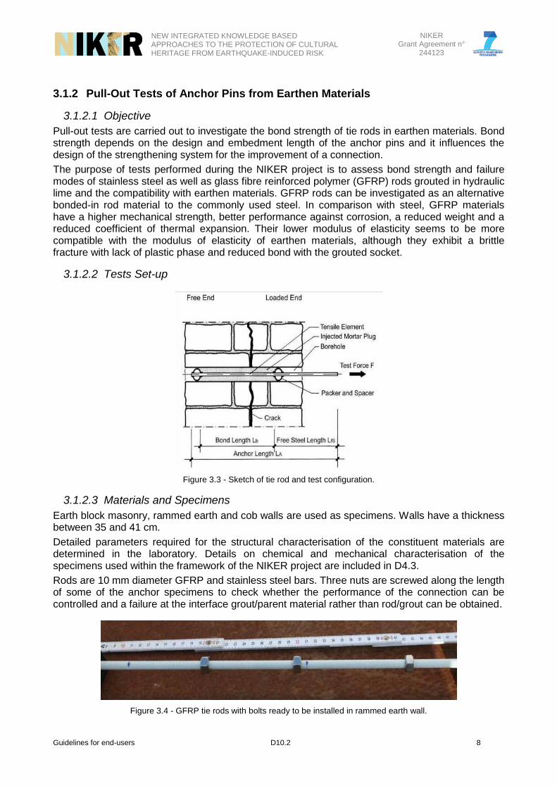
3.1.2.2 Tests Set-up
Figure 3.3 - Sketch of tie rod and test configuration.
3.1.2.3 Materials and Specimens
Earth block masonry, rammed earth and cob walls are used as specimens. Walls have a thickness between 35 and 41 cm.
Detailed parameters required for the structural characterisation of the constituent materials are determined in the laboratory. Details on chemical and mechanical characterisation of the specimens used within the framework of the NIKER project are included in D4.3.
Rods are 10 mm diameter GFRP and stainless steel bars. Three nuts are screwed along the length of some of the anchor specimens to check whether the performance of the connection can be controlled and a failure at the interface grout/parent material rather than rod/grout can be obtained.
Figure 3.4 - GFRP tie rods with bolts ready to be installed in rammed earth wall.

NEW INTEGRATED KNOWLEDGE BASED APPROACHES TO THE PROTECTION OF CULTURAL HERITAGE FROM EARTHQUAKE-INDUCED RISK
NIKER Grant Agreement n°
244123
Guidelines for end-users D10.2 9
A lime based grout is adopted. For the grout development, it is important to use materials that are readily available, cheap and industrially standardised in terms of quality. Details on grout mix design are included in D10.1 (grouting for earthen materials).
3.1.2.4 Test Procedure
Holes in the wall are drilled at a distance of no less than three diameters to avoid that pull-out results are influenced by local effects caused by reduced distance between holes. The value of the diameter of tie rods as well as the embedment length, which is equal to the thickness of the wall, are kept constant throughout the tests. Holes drilled in the earth block masonry and cob samples are sprayed with a primer before proceeding to grouting. Grouting is carried out with a specially fabricated packer-system with an inlet for the grout and an outlet for the air. A grouting pressure of 4 bars is applied and held for 2 minutes. The use of higher injection pressure is advised against as it might cause the parent material to crack and grout loss to take place. The pull-out load is applied at a rate of 100 N/s. The test consists in monotonic loading up to failure. Anchor displacements at both the loaded and the free end are recorded from an independent datum point, while anchors are loaded to failure in monotonic regime. The load is applied with a tension jack and measured with a ring dynamometer. LVDTs are used to measure the displacements of tie rods and injected mortar plug at the free end and for the tie rod displacements at the loaded end. The loaded end displacements are obtained as the average between two parallel displacement transducers so as to control rotation of the loaded end. All measurements were taken at 5 Hz frequency via a data logger and a PC.
Figure 3.5 - Test procedure (left hand side) and example of analysis of structural failure based on free-end displacements of rod and injected grout plug: combined failure of injected grout plug and of the intersection between
injected grout plug and borehole surface (Gigla 2010).
Output of tests: Graphs plotting the pull-out load against the relative displacements read at the various positions within the anchor assembly. The difference between displacements recorded in different positions allows identifying the failure mode. Once the mode of failure has been identified, one can calculate the value of performance parameters according to the methodology and formulae provided in 4.1, paragraph ´Design parameters and reference formulae´.

NEW INTEGRATED KNOWLEDGE BASED APPROACHES TO THE PROTECTION OF CULTURAL HERITAGE FROM EARTHQUAKE-INDUCED RISK
NIKER Grant Agreement n°
244123
Guidelines for end-users D10.2 10
3.1.3 Monotonic Pull-Out Test of Wall to Timber Frame Connections
3.1.3.1 Objective
In order to assess and compare the seismic performance of timber-masonry connections in Portuguese heritage structures, such as ‘Pombalino’ and ‘Gaioleiro’ buildings, a full characterization of the overall behaviour of connections as well as of original and additional materials needs to be performed. Grouted anchors are a standard option for the strengthening of connections between the outer masonry walls and the inner timber frame in these typologies of buildings and, as such, they are taken as the object of experimental investigation through pull-out tests. However, this testing procedure is also suitable for wall-to-floor connections and other types of strengthening like anchor ties with end plates.
Monotonic pull-out tests are carried out on wall-to-timber framed wall connections (unstrengthened and strengthened) in order to determine: failure modes, stress-strain behaviour and maximum pull-out force. In particular, expected failure modes for the test set-up described below are:
punching of masonry, forming a shear cone;
yielding of the steel anchor;
failure of the interface between the borehole surface and the sleeve with injected grout;
failure of the interface between the steel anchor and the injected grout.
3.1.3.2 Test Set-Up
To perform the pull-out tests without a reaction wall, a self-balanced set-up was developed, which is capable of redirecting the pull-out force back to the specimen, as shown in Figure 3.6. The pull-out load, which intends to recreate the main seismic action, was applied perpendicular to the wall in order to activate the tensile capacity of the injected anchors.
Figure 3.6 - Side elevation of the test set-up for monotonic and cyclic pull-out test of wall-to-timber frame connections.
3.1.3.3 Materials and Specimens
The specimens intend to recreate as much as possible the aspects of building construction from post earthquake Lisbon, specifically from ‘Pombalino’ and ‘Gaioleiro’ buildings. Therefore, rubble masonry panels were built using limestone from the surroundings of Lisbon and a poor lime-cement mortar to reach the mechanical properties described in literature for the masonry. The historic masonry has a compressive strength ranging from 0.8 MPa to 1 MPa and the specimens’
HEB200
Hinge
Hydraulic cylinder
Actuator

NEW INTEGRATED KNOWLEDGE BASED APPROACHES TO THE PROTECTION OF CULTURAL HERITAGE FROM EARTHQUAKE-INDUCED RISK
NIKER Grant Agreement n°
244123
Guidelines for end-users D10.2 11
masonry is designed to achieve a value slightly higher of 1.5 MPa, so that other failure modes can be observed. Samples of mortar from the walls and masonry prisms were tested to confirm the expected value of compressive stress.
Characterisation of materials is carried out according to the prescriptions of EN 1015-11 for the mortar samples and of EN 1052-1 for masonry specimens.
Sample walls are built with a thickness of 0.40m. The first value is typical of walls of the last floors of ‘Gaioleiro’ buildings.
Wall-to-timber framed wall connections only consist of strengthened specimens, without the timber frame, since the worst case scenario corresponds to inexistent connection between the timber and the masonry elements. The strengthening solution consists of two grouted anchors placed parallel to each other in the masonry wall and connected to the timber frame with steel angles. Four pairs of injected anchors are placed in each specimen, allowing 4 tests per specimen, as shown in Figure 3.7. The injected anchors were placed, on boreholes of 50 mm, spaced of 280 mm, considering that a 120 mm thick timber framed wall could fit between them. The steel bars were stainless steel AISI 304 class 70 and had a diameter of ϕ20 (wall 1) and ϕ16 (wall 2).
2000
420
760
420
380 280 680 280 380
350
400
Pair of injected
anchors
350
Figure 3.7 - Sketch and picture of strengthened wall-to-timber framed wall connection.
3.1.3.4 Test Procedure
A self-balanced system is developed to test the specimens. The pull-out load, which recreates the main seismic action, is applied perpendicularly to the wall, activating the applied strengthening solutions. A hinge is used between the actuator and the specimen, to accommodate small deformations, as shown in Figure 3.7.
In order to simulate the real behaviour of the connection, a distributed vertical load is applied on the top of the wall, simulating the contribution given by the dead load of the structure. This is achieved by HEB steel profiles placed on top of the wall, which distribute the load obtained by compressing hydraulic cylinders against a reaction slab, as seen in Figure 3.7.
To monitor the formation, behaviour and influence of the different failure modes on the final result, a set of 19 LVDTs and 8 strain gauges are used (see Figure 3.8). Injected anchors are monitored by means of strain gauges to record the variation of the stress field, as shown in Figure 3.9.

NEW INTEGRATED KNOWLEDGE BASED APPROACHES TO THE PROTECTION OF CULTURAL HERITAGE FROM EARTHQUAKE-INDUCED RISK
NIKER Grant Agreement n°
244123
Guidelines for end-users D10.2 12
15
14
5 7 86 9
2 3 4
1
10 11 12
13
16 1817
FRONT LATERALBACK
Figure 3.8 - Position of the LVDTs for strengthened wall-to-timber frame connections.
B1.1
B1.2
B1.3 B1.5
B1.4
Anchor 1 Anchor 2
B2.1 B2.3
B2.2
35
115
195
275
363
Figure 3.9 - Position of the strain gauges.
The main output of the tests are force-displacement curves, which give information on failure modes, maximum horizontal pull-out forces, bond strength between binder and parent material, bond strength between anchor and binder and shear strength of the pull-out cone. These performance parameters can be calculated according to section 4.3.

NEW INTEGRATED KNOWLEDGE BASED APPROACHES TO THE PROTECTION OF CULTURAL HERITAGE FROM EARTHQUAKE-INDUCED RISK
NIKER Grant Agreement n°
244123
Guidelines for end-users D10.2 13
3.2 TEST OF WHOLE CONNECTION
3.2.1 Cyclic Tests of T-Shape Walls
3.2.1.1 Objective
The purpose of these cyclic tests is to analyse the behaviour of a connection between two vertical elements, i.e. walls, strengthened by post-installed steel anchors, focusing on the performance of the connection and the damage deriving from cyclic loading on both the wall perpendicular and parallel to the expected main seismic action.
For the test set-up described in the following, failure is expected to occur initially by diagonal in-plane cracking of the restrained wall and eventually by failure of the head of the anchorage accordingly to one of the failure modes described in section 3.1.1.
(a)
(b)
Figure 3.10 - Expected mode of failure of T-shaped walls: a) initial formation of diagonal crack in the leg of the T due to the out-of-plane motion of the front element, eventually follower by failure of the anchorage in the front element according
to one of the modes of failure shown in (b).
The test set-up is suitable to test a range of different post-installed anchors including anchors embedded in grout or resin, or coiled metallic profiles.
3.2.1.2 Test Set-Up
Tests simulate the joint between two perpendicular walls connected by means of an anchor: samples are T shape walls where the ‘leg’ of the T reproduces the wall parallel to the main seismic action, whereas the ‘head’ of the T represents a section of a panel undergoing out-of-plane damage. The T leg is connected to a strong wall that simulates the rest of the building, whilst the T head undergoes cyclic loading that creates an overturning mechanism and the formation of a crack at the joints between the two walls (Figure 3.11). Such type of damage is recurring in historic buildings due to the lack of good quality connections, this being recreated in the sample by ensuring a scarce overlapping of bricks at the joint.

NEW INTEGRATED KNOWLEDGE BASED APPROACHES TO THE PROTECTION OF CULTURAL HERITAGE FROM EARTHQUAKE-INDUCED RISK
NIKER Grant Agreement n°
244123
Guidelines for end-users D10.2 14
Figure 3.11 - Layout of on-site application and layout of experimental simulation of cross tie at the joint between two perpendicular walls.
The connection between the walls and the strong wall is ensured by anchors, one at the bottom, running along the T leg only, the other at the top of the wall, running throughout the head and the leg of the T. While the bottom anchor works purely as restraint, the top anchor is the object of testing and its lay-out is representative of standard applications. Indeed ties are generally installed at the top of buildings and the connection to the strong wall simulates the reaction force to pull-out load due to the bond between the parent material and the anchor, which runs along a whole wall (Figure 3.12).
Figure 3.12 - Test set-up.
3.2.1.3 Materials and Samples
A total of 4 walls are built; 3 are strengthened at the connections between the two panels by standard anchors, whilst one is left unreinforced as means of comparison.
The walls are built using materials and techniques that can be representative of typical historic substrata. Characterisation of materials is carried out according to relevant Eurocodes (EN 772 - masonry units, EN 1015 –mortar, EN 1052– masonry), repeating the tests at 28 days and at the age when pull-outs are performed.
Anchors are installed according to the producer’s recommendations.
A vertical load representing the dead load of the upper structure is applied throughout the tests by steel plates compressed by tensioned threaded bars.

NEW INTEGRATED KNOWLEDGE BASED APPROACHES TO THE PROTECTION OF CULTURAL HERITAGE FROM EARTHQUAKE-INDUCED RISK
NIKER Grant Agreement n°
244123
Guidelines for end-users D10.2 15
3.2.1.4 Test Procedure
Cyclic load is applied by two hydraulic push jacks and one hydraulic pull jack restrained against the strong wall. Steel plates are used to spread the vertical load to the parent material (Figure 3.13); this load is controlled by strain gauges placed on the vertical bars that measure deformation resulting from tensioning the rods by locking the hexagonal nuts at their top end.
Tests are carried out in displacement control; the control point is at the level of the top anchor, at the midpoint of the front wall. Three cycles of loading and unloading are performed for increasing amplitude of displacement up to 10 mm of displacement or damage.
Threaded bars and steel plates for vertical load (0.05/0.1 MPa)
Push & pull jacks fixed to strong wall for horizontal cyclic loading
Figure 3.13 - Set-up of T wall.
Displacements are recorded at various level of the wall, according to the layout shown in Figure 3.12, so as to observe the displacement profile along the height of the front of each sample and the evolution of damage in the parent material and at the interface between anchor and masonry. Additionally relative displacements occurring on the side walls are manually recorded every three cycles of load by relying on a reference grid, so as to detect the formation of diagonal cracks in the load parallel to the direction of application of the cyclic load.
The test output consists of:
- graphs plotting the pull-out load against the relative displacements read at the various positions within the anchor assembly. Variations of stiffness in the graphs and the difference between displacements recorded in different positions allow identifying the failure mode;
- once the mode of failure has been identified, one can calculate the value of performance parameters according to guidelines provided in 4.2, paragraph ´Design parameters and reference formulae´.

NEW INTEGRATED KNOWLEDGE BASED APPROACHES TO THE PROTECTION OF CULTURAL HERITAGE FROM EARTHQUAKE-INDUCED RISK
NIKER Grant Agreement n°
244123
Guidelines for end-users D10.2 16
3.2.2 Cyclic Tests of Dovetail Halved Joints of Timber Roofs
3.2.2.1 Objective
The purpose of cyclic tests is to analyse the effectiveness of strengthening interventions on dovetail halved joints from the point of view of dissipative properties and change in stiffness. Different typologies of strengthening, like the addition of combined damping/reinforcing elements, e.g. steel nails, or damping elements only, e.g. brake plates, are investigated in order to describe the influence of various parameters on the improvement of the seismic capacity of the joint
3.2.2.2 Test set up
Drawing from the positive experience attained from previous tests performed at ITAM, a similar special test set-up is proposed (Figure 3.14). The arrangement allows for simulating cyclic loading and pseudo-dynamic behaviour of the dovetail halved joint separately from the roof frame. The test specimens of the joint are placed into a special testing rig. The rig enables a pseudo-dynamic cyclic loading. It also ensures the static stability of the samples and their response only in the direction of the loading.
Figure 3.14 - Test set up.
3.2.2.3 Materials and Specimens
Experiments are carried out on replicas of traditional carpentry halved dovetail joints made from original historic timber (about three hundred years old) which was taken from a demolished ancient building. The wooden elements should be free from wood-destroying fungi or wood-boring insect. Used specimens present only drying fissures and cracks.

NEW INTEGRATED KNOWLEDGE BASED APPROACHES TO THE PROTECTION OF CULTURAL HERITAGE FROM EARTHQUAKE-INDUCED RISK
NIKER Grant Agreement n°
244123
Guidelines for end-users D10.2 17
Geometry of joint assemblies as well as the extent of wood deterioration may vary. The adopted angle between the joined members is 45° which is near to the most common angles for Central European roofing frames. The geometry of specimens, locations of the acting force and the potentiometer are depicted in Figure 3.15. Furthermore, in order to assume a certain degree of joint degradation specimens present intentional assembly imperfections.
Figure 3.15 - Geometrical scheme of the joint, location of the potentiometer and of the acting force, sense of the rotation of the joint and of corresponding moment.
Material characteristics are determined by tests on samples taken from the joint assemblies. The evaluated material properties include wood density and strength. The mechanical properties of materials are summarized in Table 3.1. The values of mechanical quantities for brake plates are taken from the data guaranteed by a manufacturer.
Table 3.1 - Mechanical properties of materials.
Material Mechanical properties
Spruce
Density - ρ = 340-450 kg/m3
Compression parallel to grain R=15,63 MPa
Compression perpendicular to grain R=2,09 MPa
3.2.2.4 Test Procedure
The cyclic load was applied using a servo hydraulic MTS actuator (cylinder) with a capacity of 25 kN that is attached to a steel frame. The rotational response of the joints is measured indirectly by means of the potentiometer Megatron SPR 18-S-100 (5kΩ).

NEW INTEGRATED KNOWLEDGE BASED APPROACHES TO THE PROTECTION OF CULTURAL HERITAGE FROM EARTHQUAKE-INDUCED RISK
NIKER Grant Agreement n°
244123
Guidelines for end-users D10.2 18
Figure 3.16 - Time-histories of the measured quantities during the cyclic tests.
The specimens were cyclically loaded and the load deformation curves were registered. The load was applied on the joint using the actuator attached to the oblique beam. The intensity of the force of the actuator was controlled by its prescribed displacement. The amplitude of the controlled displacement increased for every cycle with constant step equal to 4 mm. The frequency of each cycle was chosen equal to the value 0.1 Hz. During the tests the force needed to achieve the desired displacement of the cylinder and the change of the length of the potentiometer were recorded see Figure 3.16.

NEW INTEGRATED KNOWLEDGE BASED APPROACHES TO THE PROTECTION OF CULTURAL HERITAGE FROM EARTHQUAKE-INDUCED RISK
NIKER Grant Agreement n°
244123
Guidelines for end-users D10.2 19
3.2.3 Monotonic Pull-Out Test of Timber Floor-Wall Connections
3.2.3.1 Objective
In order to assess and compare the seismic performance of timber-masonry connections in Portuguese heritage structures, such as ‘Pombalino’ and ‘Gaioleiro’ buildings, a full characterization of the overall behaviour of connections as well as of original and additional materials needs to be performed. Metallic anchors in combination with steel angle profiles are a standard option for the strengthening of connections between the masonry walls and the timber floor structure in these typologies of buildings and, as such, they are taken as the object of experimental investigation through pull-out tests. However, this testing procedure is also suitable for wall-to-timber framed wall and wall-to-wall connections, as well as other types of strengthening like injected anchors.
Monotonic pull-out tests on wall-to-floor connections (unstrengthened and strengthened) are carried out in order to determine failure modes, stress-strain behaviour and maximum pull-out force. Modes of failures that could possibly occur during tests are:
Punching of masonry, forming a shear cone;
Crushing of masonry under the anchor plate;
Yielding of the steel anchor;
Failure of the connection between the steel angle and the timber joist.
3.2.3.2 Test Set-Up
To perform the pull-out tests without a reaction wall, a self-balanced set-up was developed, which is capable of redirecting the pull-out force back to the specimen, as shown inFigure 3.17. The pull-out load, which intends to recreate the main seismic action, was applied perpendicular to the wall in order to activate the tensile capacity of the strengthening system.
Figure 3.17 - Side elevation of the test set-up for monotonic and cyclic pull-out test of wall-to-floor connections.
3.2.3.3 Materials and Specimens
The specimens intend to recreate as much as possible the aspects of building construction from post earthquake Lisbon, specifically from ‘Pombalino’ and ‘Gaioleiro’ buildings. Therefore, rubble masonry panels were built using limestone from the surroundings of Lisbon and a poor lime-cement mortar to reach the mechanical properties described in literature for the masonry. The historic masonry has a compressive strength ranging from 0.8 MPa to 1 MPa and the specimens’
Hinge
Hydraulic cylinder
HEB200
Actuator

NEW INTEGRATED KNOWLEDGE BASED APPROACHES TO THE PROTECTION OF CULTURAL HERITAGE FROM EARTHQUAKE-INDUCED RISK
NIKER Grant Agreement n°
244123
Guidelines for end-users D10.2 20
masonry is designed to achieve a slightly higher value of 1.5 MPa, so that other failure modes can be observed. Samples of mortar from the walls and masonry prisms were tested to confirm the expected value of compressive stress.
Characterisation of materials is carried out according to the prescriptions of EN 1015-11 for the mortar samples and of EN 1052-1 for masonry specimens.
Test walls are built with a thickness of either 0.40 m or 0.60 m. The first value is typical of walls of the last floors of ‘Gaioleiro’ buildings, while the second one was used in all the walls of ‘Pombalino’ buildings, with the exception of the 1st floor. Different thicknesses are associated with distinct vertical stress values, since the amount of stress is related to the location of the wall in the building and decreases from lower to upper floors.
Wall-to-floor connections are analysed through unstrengthened and strengthened specimens. The specimens feature a timber beam of 0.095x0.095 m2 laid along the wall and connected to perpendicular timber beams of 0.13x0.18 m2 spaced at 0.38 m. Only two of the perpendicular timber beams are extended beyond the walls, since only these two are tested, as shown in Figure 3.18. Used timber is of the species Pinus Silvestris, which was commonly applied in timber elements of Portuguese historical buildings.
The specimens are strengthened with a system involving steel ties, at an angle of 15º, anchoring the timber beams to the masonry wall, with anchor plates placed on the external surface of the wall (Figure 3.18).
60
0
15°
30
380 380 380 380
50
0
500 1000 500 400
1600
40
0
(a) (b)
Figure 3.18 - Sketch of the constructed specimens (a) strengthened wall-to-floor connection and (b) strengthened wall-to-timber frame connection.
3.2.3.4 Test Procedure
A self-balanced system is developed to test the specimens. The pull-out load, which intends to recreate the main seismic action, is applied perpendicularly to the wall, activating the applied strengthening solutions. A hinge is used between the actuator and the specimen, to accommodate small deformations, as shown in Figure 3.17.
In order to simulate the real behaviour of the connection, a distributed vertical load is applied on the top of the wall, simulating the contribution given by the dead load of the structure. This is achieved by HEB steel profiles placed on top of the wall, which distribute the load applied by compressing hydraulic cylinders against a reaction slab, as seen in Figure 3.17.

NEW INTEGRATED KNOWLEDGE BASED APPROACHES TO THE PROTECTION OF CULTURAL HERITAGE FROM EARTHQUAKE-INDUCED RISK
NIKER Grant Agreement n°
244123
Guidelines for end-users D10.2 21
To monitor the formation, behaviour and influence of the different failure modes on the final result, a set of 19 LVDTs and two strain gauges are used (Figure 3.18). The two strain gauges are applied parallel to each other in the middle of the steel tie to control stress distribution.
14
1
2
63 4 87
11
12
10
9
13
15
16
17
18
5
FRONT LATERALBACK
Figure 3.19 - Position of the LVDTs for strengthened wall-to-floor connections.
The main output of the tests are force-displacement curves, which give information on failure modes, maximum horizontal pull-out forces, deformation of the system, shear strength of the pull-out cone. These performance parameters can be calculated according to the guidelines provided in 4.4.

NEW INTEGRATED KNOWLEDGE BASED APPROACHES TO THE PROTECTION OF CULTURAL HERITAGE FROM EARTHQUAKE-INDUCED RISK
NIKER Grant Agreement n°
244123
Guidelines for end-users D10.2 22
3.3 TEST OF WHOLE STRUCTURE
3.3.1 Shaking Table Tests of Timber-Laced Structure
3.3.1.1 Objective
Shaking table tests are suitable to test any type of strengthening system for connections as long as this is used without the addition of any other strengthening intervention that may create difficulties in assessing the effect of each technique on the overall dynamic behaviour of the structure.
For instance, within the NIKER project, shaking table bi-axial tests were performed on two building models in the unreinforced and reinforced set-ups to the aim to assess the effect of horizontal timber ties on the connection between walls, as well as on the connection of the leaves of the three-leaf stone masonry (Mouzakis et al., 2012; Adami et al., 2012; Vintzileou et al., 2012).
In fact, timber-lacing cannot be considered as a strengthening technique for connections; yet, it is a traditional structural system (already in place within the structure) in earthquake prone areas all over the world. The system has not yet been investigated so far in a systematic way; however, it became evident from the tests that timber-lacing has a significant positive effect on the overall response of the structure by delaying the opening of the cracks (which are formed for higher seismic input), as well as by reducing their width and length. Therefore when timber lacing is embedded in a structure as part of the original building should be repaired or/and maintained.
In general, expected modes of failure during bi-axial shaking tables on three-leaf masonry building models (with or without timber lacing) are:
a) formation of vertical cracks at the corners of the buildings and detachment of the leaves of masonry due to out-of plane bending of the walls (and due to flexible diaphragms);
b) formation of shear cracks in the corners of openings and in the walls with small aspect ratio.
It should be mentioned that the governing effect, flexural or shear respectively, depends on the geometry of piers.
In the following sections of Chapter 3.3, general information/guidelines for the execution of shaking table tests on building models are provided.
3.3.1.2 Test Procedure
In general, shaking table tests are performed according to a standard procedure (reference can be for instance found in: Tomaževic et al., 1992; Jurukovsky et al., 1992; Benedetti et al., 1998; Chung et al., 1999; Zonta et al., 2001; Zarni ., 2001; Li et al. 2006; Mazzon et al., 2009; Mouzakis et al., 2012; Adami et al., 2012). Specimens can be tested at full scale, if the capacity of the shaking table allows for that, or at reduced scale; within the framework of the NIKER project a geometrical reduction of 2 times was considered and the same materials of the prototype building were employed:
a) specimens are built to be representative of realistic prototypes, both in terms of geometry and construction materials; appropriate scaling laws are applied to achieve similitude in dynamic behaviour between model and prototype. The same similitude law used for the geometry and the loads is also applied to the seismic input;
b) a preliminary motion (of low acceleration) that allows for both the dynamic identification of model and the detection of damage effects on the dynamic characteristics is applied to the model. This step is repeated before the input of each subsequent increasing seismic motion;
c) a seismic motion is selected as input and is scaled to become adequate for application to the model. Input signals are chosen so as to activate the natural vibration frequency of the specimen and be representative of the seismic events that typically occur in the geographical area where the prototype buildings are a recurring structural typology;
d) a series of subsequent scaled motions with increasing intensity is applied to the model. Tests are repeated until the model is damaged to a level that allows for its safe removal

NEW INTEGRATED KNOWLEDGE BASED APPROACHES TO THE PROTECTION OF CULTURAL HERITAGE FROM EARTHQUAKE-INDUCED RISK
NIKER Grant Agreement n°
244123
Guidelines for end-users D10.2 23
from the table. The steps of intensity increase of the input signal ranges between 5% and 20% of the peak acceleration of the original seismic motion;
e) after damaging the model to the predefined level, the model is removed from the table;
f) if the tested specimen is used to study the effect of different intervention techniques on the dynamic behaviour of structures, after point (d), strengthening is applied to the model. The model, after the time period required for curing and of the full development of mechanical strength of the added materials, is placed again on the shaking table and retested to extensive damages, repeating the testing procedure described in points d and e.
The design of a test model for earthquake simulator, as well as the planning of the sequence of tests, should be supported by computational analysis. This is a multi-purpose analytical work that should be carried out before and during testing.
3.3.1.3 Materials and Specimens
For any facility that may be available for model testing, there are limitations for the models that result from the specific characteristics of the simulator, namely:
a) geometrical limitations: The dimensions of the platform limit the plan dimensions of the model. The maximum allowable height of the centre of gravity of the model is also dictated by the characteristics of the simulator;
b) mass limitations: The performance of the simulator is affected by the model placed on it. There is a maximum weight the model should not exceed, so that the performance of the simulator is not significantly affected.
Therefore, the design of any model should take into account the aforementioned limitations, in order to produce a model that the facility is able to damage or even to bring to collapse (depending on the experimental program provisions) and to, simultaneously, protect the earthquake simulator from misuse.
In order to comply with these limitations, models are built in a reduced scale according to appropriate scaling laws to achieve similitude between model and prototype. Materials typical of the prototype structure should be used for the construction of the model; if this is not possible, materials should be chosen so as to reproduce as closely as possible the mechanical properties of original materials. The geometry and layout of horizontal elements is again decided on the basis of the analysed prototype structure.
The same concept also applies to the timber lacing. In a typical layout, timber ties are for instance positioned:
a) at floor levels (0,1m lower than the upper level of bearing timber beams of the floor, as timber ties serve as collector beams);
b) at the top of all openings; c) at the bottom of openings.
Timber ties usually are connected with timber frames around openings. Dimensions, distribution, arrangement and connection of timber lacing elements should be decided on the basis of accurate literature reviews and on-site surveys, so as to representative of realistic case studies.
3.3.1.4 Test Set-up
The specimen must be securely fastened on the shaking table through a rigid steel base. The model should be accurately instrumented before testing to monitor its overall behaviour. Accelerations should be measured at various places, according to the expected behaviour of the model. Furthermore, shear deformations and both in- and out-of-plane displacements should be measured by means of extensometers positioned in adequate locations (according to the results of the analytical work). Besides, the use of optical systems (based on the triangulation of directions) allows the displacement of a larger number of points to be monitored. Where needed, an independent frame may be located out of the table to allow for absolute displacements to be recorded. It should be noted that, some critical displacements/deformations should be assessed

NEW INTEGRATED KNOWLEDGE BASED APPROACHES TO THE PROTECTION OF CULTURAL HERITAGE FROM EARTHQUAKE-INDUCED RISK
NIKER Grant Agreement n°
244123
Guidelines for end-users D10.2 24
after each loading step. If needed, instruments may be added or moved to other locations that may prove to be more critical.
Before testing, instrumentation (reported on adequate drawings and sketches) including the type of instrument, the measurements to be recorded and the accuracy of measurements has to be provided.
An example of instrumentation set-up is shown Figure 3.20.
a) b)
Figure 3.20 - Measurement points of a) acceleration and b) displacement.
Main output to be pursued by shaking table tests is:
- crack pattern and crack width, which allow for the identification of the failure mechanism;
- dynamic properties, maximum seismic input, maximum top accelerations, lateral inter-storey drift values;
- capacity curves of the tested model (the envelope curves of the hysteretic loops obtained during the experimental procedure in which the structure is subjected to increased step-wise base motion). The capacity curve is given in terms of base shear and top relative displacement. These curves give information about the bearing capacity, the deformability and the stiffness of the structure.
For timber laced-masonry structure, further tests should be performed in order to be able to express a judgement regarding the performance of the system depending on boundary conditions, materials and so forth. A draft procedure for the identification and use of performance parameters for the assessment of this type of buildings is given in 4.4, paragraph ´Design parameters and reference formulae´.
LW1
SW1
LW2 SW2

NEW INTEGRATED KNOWLEDGE BASED APPROACHES TO THE PROTECTION OF CULTURAL HERITAGE FROM EARTHQUAKE-INDUCED RISK
NIKER Grant Agreement n°
244123
Guidelines for end-users D10.2 25
4 IMPROVEMENT OF CONNECTIONS
In Chapter 3, a set of experimental procedures for the assessment of connections of historic structures both in the unreinforced and strengthened set-up has been described. By following the provided guidance, end-users can carry out laboratory experiments that aid the understanding of how a specific connection behaves and whether a certain type of strengthening can or not improve its dynamic response.
Once the need for repair and upgrade of a structural connection has been identified, a suitable strengthening system needs choosing and designing. In this chapter, advantages and drawbacks of the various techniques considered within the project framework (for a summary see table below), as well as the criteria for correct on-site implementation are listed. As such, Chapter 4 exemplifies how to achieve a comprehensive approach to the problem of interventions on historic buildings: a strengthening intervention should indeed not only consider structural-related issues, but also on-site constraints, compatibility with original materials and other strengthening systems, architectonic impact and so on. Such information is both summarised in a set of tables and detailed in writing in the following paragraphs.
Furthermore, as very few prescriptions are given by current design codes in terms of procedures to follow when dimensioning the strengthening for the repair and upgrade of connections, Chapter 4 shows how results of experimental campaigns described in Chapter 3 can be used in the design process.
Each strengthening system is divided into sub-components to which one type of failure controlled by a single parameter can be associated. The whole set of these parameters determines the global response of the system, as each identifies a capacity and can be correlated to an analytical model, thus allowing the dimensioning of the strengthening system according to a hierarchical process of components’ failure. Individual components and system capacities can be calculated through the formulae prescribed by design codes, whereas input values are derived from tests or, alternatively, from producers’ specifications and code requirements, if any.
Accordingly, each section of this chapter include a table: the column “Achievable range” collects the values obtained during tests performed within the NIKER project and that could be integrated by performing tests on difference specimens, following indications provided in Chapter 3. The column “Expected range” refers instead to code prescriptions; when these are not available, the authors suggest an analytical model on the basis of their experience and of the output of the research project. The information provided in this chapter is not exhaustive of the whole range of products available in the market and is therefore meant to be used as guidance and example when considering further scenarios.
In particular, it is recommended that designers:
1. analytically assess the capacity of the existing connection, this being either unreinforced or reinforced by traditional systems embedded in the masonry fabric (e.g. timber lacing). The analytical output can be compared against experimental results by performing tests on unreinforced specimens by means of the testing procedures suggested in Chapter 3;
2. once it has been verified that the unreinforced/reinforced set-up is not able to withstand the required level of seismic excitation, a strengthening system is chosen taking into account the various factors listed in Chapter 4; it is suggested that a similar template is used when comparing further strengthening techniques that might not be included in the following.
3. the strengthening system is designed considering the capacity of its components according to the performance parameter tables. Breakdown of the assembly should be carried out drawing on this document should the considered strengthening system be not treated in the following;
4. tests are performed following the guidelines of Chapter 3, so as to obtain the performance parameters needed in the design process.

NEW INTEGRATED KNOWLEDGE BASED APPROACHES TO THE PROTECTION OF CULTURAL HERITAGE FROM EARTHQUAKE-INDUCED RISK
NIKER Grant Agreement n°
244123
Guidelines for end-users D10.2 26
For instance, considering two orthogonal walls connected by means of quoins or key stones subjected to seismic excitation: in the unstrengthened set-up, the portions of key stones in contact with each other will tend to slide in the direction of motion, while the portion of the key-stone inserted in the ordinary masonry will serve as anchorage.
For the connection to be effective, it must be:
2
2
111 )(2 FnbHaMF (1)
where the left hand side of the equation is the action of the mass of the wall M times the lateral acceleration a and the right hand side is the restraining action by friction as developed at the interface of the two sets of quoins, where φ1 is the friction coefficient, n is the number of contact surfaces and b the size of the surfaces in contact (if key stones have the same dimensions).
The normal stress σ1 can be assumed for simplicity constant over each contact surface, but variable with the wall’s height H, from 0 at the top to a maximum at the base dependent on the loading condition. Moreover for the restraining action F2 to be effective the stones in the direction parallel to the action need to be well set in the in-plane wall and the bond between keystones and ordinary masonry needs to be effective.
This relies on the interlocking of the keystone with smaller stones and the bond with the mortar.
For each keystone:
32222
2
112 ))](([2)(2/ FhbcbblHcbHnF (2)
where c2 is the mortar bond strength, φ2 the coefficient of friction between keystone and rest of the masonry, l is the total length of the keystone and h its height.
Of course in this first very simple example only the sliding effect of one wall past the other is considered, but in reality due to the interlocking of the stones and the position of the resultant of forces, also rotational effects will come into play.
These however will only develop if the sliding is prevented, i.e. if the bonding is efficient. And hence this is the minimum lateral force that the connection is able to withstand.
The whole system relies on the assumption that the tensile strength of the stone is higher than the bond and friction resistance of the bonding mortar. For each keystone:
422223 ))](([2 FhbfhbcbblHcF st (3)
where fst is the tensile strength of the stone.
By equations (1) to (3) it is possible to determine whether the size of the quoin stones is sufficient to ensure that the corner connections will be able to withstand a certain seismic action without any slippage and failure. Geometry data can be measured on site, whilst the tensile strength of the stone and the friction coefficients should be either derived by tests or obtained from the technical literature.
Now, assuming that the size of the stones is not sufficient to prevent the detachment of the two walls and that cross-ties have been selected to strengthen the connection, the capacity of the system can be quantified as follows:
2
2
14
Fnfd
aMF y (4)

NEW INTEGRATED KNOWLEDGE BASED APPROACHES TO THE PROTECTION OF CULTURAL HERITAGE FROM EARTHQUAKE-INDUCED RISK
NIKER Grant Agreement n°
244123
Guidelines for end-users D10.2 27
where d is the bar diameter, fy is the yield strength of the iron or steel and n the number of anchors that is supposed to restrain the volume of the mass M of the wall.
The force F2 can be transferred to the wall in various ways depending on whether the anchor is in direct contact and bonded to the masonry or it is anchored by means of a plate. In the first case:
322 FlfdF b (5)
where d2 is the diameter of either the anchor itself or of a grouted cylinder around the anchor, depending on whether this exists or not, l is the length of anchor grouted or directly bonded to the masonry and fb the bond strength.
In the second case:
322 )(2 FdllF k (6)
where l is the depth of the wall that can be punched through, d2 is the diameter of either the anchor itself or of a grouted cylinder around the anchor and τk is the characteristic shear strength of the masonry. Equation (6) can be used to size the anchoring plate as a square of side equal to 2(l+d2) or of equivalent diameter.
It should be noted that the satisfaction of condition in equation (5) does not necessarily exclude the possibility of non compliance with equation (6) as although the resisting surface in (6) can be wider, the shear characteristic strength can be lower than the bond strength, especially if mechanical locking is occurring.
Again, some parameters in equations (5) and (6), like bond and shear strength, will either be derived by data from technical literature or quantified by performing appropriate experiments.
Similarly to what just shown, design of strengthening systems for connections can be performed by looking at the performance parameters, formulae and literature references provided in this chapter.

NEW INTEGRATED KNOWLEDGE BASED APPROACHES TO THE PROTECTION OF CULTURAL HERITAGE FROM EARTHQUAKE-INDUCED RISK
NIKER Grant Agreement n°
244123
Guidelines for end-users D10.2 28
The table below outlines the strengthening techniques for connections developed in the context of NIKER:
CONNECTIONS
INTERVENTION APPLICATION
Ref. Section
Type Type of connection
Material Prevented failure mechanism
Repaired damage / Improved performance
4.1 Grouted metallic anchor
Wall to wall Brickwork masonry
Cracking at the joint of the two walls, overturning/out-of-plane failure of walls
Restored connection between vertical elements so as to ensure redistribution of loads depending on the stiffness of bearing elements and achieve better global performance
4.2 Anchor pins Wall to wall Earthen materials
Cracking at the joint of the two walls, overturning/out-of-plane failure of walls
Restored connection between vertical elements so as to ensure redistribution of loads depending on the stiffness of bearing elements and achieve better global performance
4.3 Grouted metallic anchors
Wall to timber frame
Rubble stone wall and timber frame
Overturning/out-of-plane failure of walls
Restored connection between vertical elements so as to ensure redistribution of loads depending on the stiffness of bearing elements and achieve better global performance
4.4 Metallic tie + steel angle
Wall to timber floor
Rubble stone wall and timber floor
Overturning/out-of-plane failure of walls
Restored connection between vertical and horizontal elements so as to ensure redistribution of loads depending on the stiffness of bearing elements and achieve better global performance
4.5 Strengthening by various techniques
Carpentry halved joints
Timber decrease the overall roof frame deformation during horizontal wind or earthquake loads
increase in dissipation energy during cycling
4.6 Timber lacing Wall to wall connection and connection between masonry leaves
Stone masonry with rubble infill and timber lacing
N/A Delay and limitation of:
-cracks at the wall-to-wall connection
-detachment of leaves

NEW INTEGRATED KNOWLEDGE BASED APPROACHES TO THE PROTECTION OF CULTURAL HERITAGE FROM EARTHQUAKE-INDUCED RISK
NIKER Grant Agreement n°
244123
Guidelines for end-users D10.2 29
4.1 GROUTED METALLIC ANCHORS ENCASED IN FABRIC SOCK
Grouted metallic anchors encase in fabric sock
Design parameters Applicability Advantages and limits
- Tensile strength of metallic anchor rod;
- Bond strength between anchor rod and binder;
- Bond strength between binder and parent material;
- Tensile strength of parent material;
- Bond strength at mortar joints
Generally applicable. In case of particularly weak or loose substrata, the performance of the strengthening system is improved by grouting of parent material.
Advantages
- Negligible increase in mass;
- No aesthetic impact;
- Reversibility.
Limits
- Presence of precious finishes and geometry of the building might restrict prevent the possibility of drilling anchors in the required position.
Definition and Purpose
Grouted metallic anchors comprise a stainless steel profile encased in a fabric sleeve that is installed in holes drilled in the structure and then injected by grout. The flexible sleeve of woven polyester restrains the grout flow and expands to about twice its normal diameter, moulding itself into the shape and spaces within the walls, providing mechanical as well as chemical bond. Therefore, the anchoring system relies on shear and mechanical locking for the transmission of load to the substratum, and no end plate is needed.
The system is used to restore the connection between vertical elements or vertical to horizontal elements thus ensuring the redistribution of loads depending on the stiffness of the bearing elements, the prevention of out-of-plane mechanisms and a better dynamic response of the structure.
Applicability Conditions
The system is generally applicable. In case of particularly weak or loose substrata, anchors will benefit from application of grouting; grouting will indeed ensure that the parent material is able to transmit the tensile load applied to the anchor by a perpendicular wall undergoing seismic out-of-plane excitation.

NEW INTEGRATED KNOWLEDGE BASED APPROACHES TO THE PROTECTION OF CULTURAL HERITAGE FROM EARTHQUAKE-INDUCED RISK
NIKER Grant Agreement n°
244123
Guidelines for end-users D10.2 30
Design Parameters and Reference Formulae
Performance parameters Achievable range Expected range
1) Fsteel: tensile capacity of metallic bar at yielding [kN]
Fsteel=71 kN (for M16 threaded bar - values stated by producer)
Fsteel=71 kN; calculated as: Fsteel=fyA
with fy yielding strength of steel and A net cross sectional area of metallic profile (EN 1993-1-1:2005)
2) fb a/b: bond strength anchor/binder [MPa] calculated on cylindrical surface of embedded bar
Calculated as: fb a/b=Fs/b bond/Asteel with Fs/b bond recorded load at failure and Asteel cylindrical lateral surface calculated as: Asteel=πldpitch with l embedment length and dpitch pitch diameter of steel bar. For pull-out tests of M16 threaded bars from 550 mm long grouted socks:
fb a/b=2.07 MPa (CoV 4%)
fb a/b= 3.4 MPa – design value suggested in BS 5268-2 for tested binder, bar diameter and type of bar 2 MPa – design value suggested in EN 1996-1-1:2005 for tested binder and type of application
3) fb b/p: bond strength binder/parent material [MPa] calculated on cylindrical surface of grouted socket
Calculated as: fb b/p=Fb/p bond/Ahole with Fb/p bond recorded load at failure and Ahole inner cylindrical surface of drilled hole of length l. For pull-out tests with vertical load on masonry specimens σd:
Calculated as: fb b/p=fvk=fvk,0+0.4σd with fvk,0 initial shear strength (calculated through experimental results) and σd vertical load (EN 1996-1-1:2005).
l [mm] σd
[MPa] fb b/p [MPa] σd [MPa] fb b/p [MPa]
Brick masonry, fc=6.7 MPa, fw=0.7 MPa
350 0.70 0.67 (CoV 8%) 0.7 0.52
0.07 0.57 (CoV 18%) 0.07 0.27
Brick masonry fc=3.1 MPa, fw=0.33 MPa
220 0.10 0.26 (CoV 34%) 0.10 0.08
0.05 0.4 0.05 0.06
4) fmasonry: Shear strength of parent material [N/mm
2]
This type failure, although expected, did not occur during experimental campaigns
Calculated as: fmasonry=fvk=fvk,0+0.4σd
(EN 1996-1-1:2005). In the tested case it would be expected:
0.52 MPa 0.27 MPa
The failure surface, Af, is a truncated cone with smallest base corresponding to the drilled hole, apothem inclined at 45° and height equal to the wall thickness
5) fmasonry: Tensile strength of parent material [N/mm
2]
A “wrench” failure occurs instead of the expected “cone pull-out” failure. Failure surface, Af, develops along vertical joints.
fmasonry=fw=0.67 MPa (from wrench test)
No mention about this type of failure has been found in the technical literature or design codes.
Execution
The execution of an intervention by grouted anchors should be carried out according to the producer’s instructions. Below some general recommendation regarding the execution are given as guidelines.
Drilling
Carefully set out the anchor position using a wax crayon or chalk, as per specifications, or as directed by the structural engineer or supervisor.

NEW INTEGRATED KNOWLEDGE BASED APPROACHES TO THE PROTECTION OF CULTURAL HERITAGE FROM EARTHQUAKE-INDUCED RISK
NIKER Grant Agreement n°
244123
Guidelines for end-users D10.2 31
Select the drilling method specified; for heritage buildings, due to the weakness and preciousness of the parent material, dry/ wet diamond rotary drilling rather than percussive drilling is recommended.
Drill the hole to the required embedment depth. Remove all cores from the bore hole and check the depth. Remove dust and debris from the wall and clean all stains immediately.
Anchor Insertion and grouting
Carefully unpack the anchor and check there has been no damage to the fabric sock during transit. Small tears or rips in the sock can be repaired using a needle and strong cotton or a hot melt glue stick. Do not shorten the length of the sock on the anchor.
Immediately prior to insertion wet the anchor completely with clean water, and position the sock evenly along the length of the anchor.
N.B. Do not allow the sock to remain completely saturated with water for a long period as this may cause the fabric sock to shrink.
Place the anchor in the bore hole and carefully push the anchor in lifting it over any fissures or voids, do not force or twist the anchor into the hole.
Install the anchor to within 50mm of the face of the brickwork (do not push completely in.)
When inserting the anchor ensure that the injection tube is towards the top of the borehole - never force or twist the anchor into the hole.
When mixing the grout, the water content can be increased by up to 10% e.g., 25 kg (56 lbs) of grout to 5.5 litres of water+ 10% = 6.05 litres. Cut mastic nozzle to fit over the injection tube.
When inflating anchor slowly rotate the anchor in the borehole to facilitate the grout flow and to ensure the anchor is centralised on completion. Maintain the pressure until all the grout milk has been expelled.
Cold Weather Grouting
The installer shall ensure that the minimum temperature of the grout at the time of injection is 7°C and the temperature of the injected grout does not fall below 5°C for a period of 24 hours from the beginning of inflation.
Where these conditions are not applicable, then:
- the pressure pot and delivery hose should be lagged with a suitable insulating material;
- the grout, anchors and pressure pot must be stored in a container or room with a temperature of no less than 10°C;
- the clean water used for mixing must be within the temperature range of 15°C-20°C (59°F-68°F);
- the borehole temperature must not be below 0°C and no ice crystals must be present on the surface of the bore hole;
- a suitable shelter needs to be used for the mixing process;
- a screen needs to be erected around the installation area to avoid any wind chill;
- after drilling the bore hole install a suitable plug to maintain a constant core temperature;
- allow the outside temperature to rise before injecting the grout, i.e. do not inflate first thing in the morning or last thing in the afternoon;
- immediately after inflation install insulation in the front of the bore hole.
Hot Weather Grouting
In very hot climates the maximum temperature of the grout at time of injection must not exceed 20°C. If this is not the case, then clean water used for mixing must be cooled to 15°C (59°F). The pressure pot and the bore hole must be shielded from direct sunlight; in extreme conditions the pressure pot must be placed in a vat of cooled water or ice.

NEW INTEGRATED KNOWLEDGE BASED APPROACHES TO THE PROTECTION OF CULTURAL HERITAGE FROM EARTHQUAKE-INDUCED RISK
NIKER Grant Agreement n°
244123
Guidelines for end-users D10.2 32
In-Situ Testing
Pull-out tests can be performed on-site to check the capacity of anchors.
Advantages and Limits
Advantages:
- restoration of box-like behaviour with negligible increase in mass. This is a main advantage of systems involving metallic anchors, which are able to restore connections and hence a unitary response of the building. Horizontal loads are distributed among bearing walls according to their stiffness. Increase of mass, which is associated to the use of systems such as concrete ring beam, is avoided, thus preventing damage and collapse associated to a concentration of mass at the level of horizontal structures;
- no aesthetic impact. Anchors are embedded within the masonry and, as such they can be conceived;
- reversibility. Anchors can be over drilled; however, this process might results intrusive and disruptive, therefore it should be avoided as much as possible.
Limits:
- presence of precious finishes and geometry of the building might restrict or prevent the possibility of drilling anchors in the required position.
Recommendations and References EN 846-2:2000 - Methods of test for ancillary components of masonry - Determination of bond
strength of prefabricated bed joint reinforcement in mortar joints.
EN 1881:2006 - Products and systems for the protection and repair of concrete structures — Test methods — Testing of anchoring products by the pull-out method.
EN 1996-1-1: 2005. Eurocode 6 – Design of Masonry Structures.

NEW INTEGRATED KNOWLEDGE BASED APPROACHES TO THE PROTECTION OF CULTURAL HERITAGE FROM EARTHQUAKE-INDUCED RISK
NIKER Grant Agreement n°
244123
Guidelines for end-users D10.2 33
4.2 ANCHOR PINS IN EARTHEN MATERIALS
Anchor pins in earthen materials
Design parameters Applicability Advantages and limits
- Tensile strength of metallic anchor rod;
- Bond strength between anchor rod and binder;
- Bond strength between binder and parent material;
- Tensile strength of parent material;
- Bond strength at mortar joints
Generally applicable. In case of particularly weak or loose substrata, the performance of the strengthening system is improved by grouting of parent material.
Advantages
- Negligible increase in mass;
- No aesthetic impact;
- Reversibility.
Limits
- Presence of precious finishes and geometry of the building might restrict prevent the possibility of drilling anchors in the required position.
Definition and Purpose
Grouted anchors are made of a stainless steel or GFRP rod (with or without nuts) that is installed in holes drilled in the structure and then injected by grout. The grout flow moulds itself into the shape and spaces within the walls, providing mechanical bond. Therefore, the anchoring system relies on shear and mechanical locking for the transmission of load to the substrate, and no end plate is needed.
The system is used to restore the connection between vertical elements or vertical to horizontal elements thus ensuring the redistribution of loads depending on the stiffness of the bearing elements, the prevention of out-of-plane mechanisms and a better dynamic response of the structure.
Applicability Conditions
The system is generally applicable. In case of particularly weak or loose substrates, anchors will benefit from application of grouting; grouting will indeed ensure that the parent material is able to transmit the tensile load applied to the anchor by a perpendicular wall undergoing seismic out-of-plane excitation.

NEW INTEGRATED KNOWLEDGE BASED APPROACHES TO THE PROTECTION OF CULTURAL HERITAGE FROM EARTHQUAKE-INDUCED RISK
NIKER Grant Agreement n°
244123
Guidelines for end-users D10.2 34
Design Parameters and Reference Formulae
Typology of strengthening
Performance parameters Achievable range Expected range
Con
ne
ction
vert
ica
l/ v
ert
ica
l o
r ve
rtic
al/h
orizon
tal e
lem
en
ts
Anchoring systems without end plates
Tensile capacity (N) as minimum depending on:
1) Fanchor: tensile capacity
of anchor rod (N) 1)
a. Stainless steel profile: 26 kN (M10, class 5.8) – Data by supplier
b. GFRP profile: 14.5 kN (Φ 10 mm)
1)
a. 25 kN, calculated with fy yielding strength of steel and A net cross
sectional area of metallic profile (EN 1993-1-1:2005)
b. Data provided by producer
2) fb a/b: bond strength
anchor/binder (N/mm2)
calculated on the cylindrical surface of the embedded bar
2) Derived from tests as:
fb a/b=fb=Fa/b bond/Aanchor
with Fa/b bond recorded maximum load and Aanchor cylindrical lateral
surface calculated as:
Aanchor=πldpitch
with l embedment length and dpitch
pitch diameter of bar:
No reference value or parameter to be found in technical literature or design codes
Earth block masonry:
0.53 MPa (GFRP)
Cob:
0.46 MPa(Steel)
0.45 MPa (GFRP)
3) fb b/p: Bond strength
binder/parent material (N/mm
2) calculated on the
cylindrical surface of the grouted socket
3) Calculated from tests as:
fb b/p=fb=Fb/p bond/Ahole
with Fb/p bond recorded maximum load and Ahole inner cylindrical
surface of drilled hole:
No reference value or parameter to be found in technical literature or design codes
Earth block masonry:
0.42 MPa (Steel + nuts)
0.32 MPa(GFRP + nuts)
Cob:
0.24 MPa (GFRP + nuts)
Execution
The execution of an intervention by grouted anchors should be carried out according to the producer’s instructions. Below some general recommendation regarding the execution are given as guidelines.
Drilling
Carefully set out the anchor position using a wax crayon or chalk, as per specifications, or as directed by the structural engineer or supervisor.
Select the drilling method specified; for heritage buildings, due to the weakness and preciousness of the parent material, dry diamond rotary drilling rather than percussive drilling is recommended.
Drill the hole to the required embedment depth. Remove all cores from the bore hole and check the depth. Remove dust and debris from the wall and clean all stains immediately.

NEW INTEGRATED KNOWLEDGE BASED APPROACHES TO THE PROTECTION OF CULTURAL HERITAGE FROM EARTHQUAKE-INDUCED RISK
NIKER Grant Agreement n°
244123
Guidelines for end-users D10.2 35
Anchor Insertion and grouting
Place the anchor in the bore hole and carefully push the anchor in lifting it over any fissures or voids, do not force or twist the anchor into the hole.
Install the anchor to within 50mm of the face of the wall (do not push completely in.)
When inserting the anchor ensure that the injection tube is towards the top of the borehole - never force or twist the anchor into the hole.
Details on grouting procedure are included in D10.1 (grouting for earthen walls)
When mixing the grout, the water content can be increased by up to 10% e.g., 25 kg of grout to 5.5 litres of water+ 10% = 6.05 litres. Cut mastic nozzle to fit over the injection tube.
Cold Weather Grouting
The installer shall ensure that the minimum temperature of the grout at the time of injection is 7°C and the temperature of the injected grout does not fall below 5°C for a period of 24 hours from the beginning of inflation.
Where these conditions are not applicable, then:
- the pressure pot and delivery hose should be lagged with a suitable insulating material;
- the grout, anchors and pressure pot must be stored in a container or room with a temperature of no less than 10°C;
- the clean water used for mixing must be within the temperature range of 15°C-20°C.
- the borehole temperature must not be below 0°C and no ice crystals must be present on the surface of the bore hole;
- a suitable shelter needs to be used for the mixing process;
- a screen needs to be erected around the installation area to avoid any wind chill;
- after drilling the bore hole install a suitable plug to maintain a constant core temperature;
- allow the outside temperature to rise before injecting the grout, i.e. do not inflate first thing in the morning or last thing in the afternoon;
- immediately after inflation install insulation in the front of the bore hole.
Hot Weather Grouting
In very hot climates the maximum temperature of the grout at time of injection must not exceed 20°C. If this is not the case, then clean water used for mixing must be cooled to 15°C.The pressure pot and the bore hole must be shielded from direct sunlight; in extreme conditions the pressure pot must be placed in a vat of cooled water or ice.
In-Situ Testing
Pull-out tests can be performed on-site to check the capacity of anchors.
Advantages and Limits
Advantages:
- restoration of box-like behaviour with negligible increase in mass. This is a main advantage of systems involving metallic anchors, which are able to restore connections and hence a unitary response of the building. Horizontal loads are distributed among bearing walls according to their stiffness. Increase of mass, which is associated to the use of systems such as concrete ring beam, is avoided, thus preventing damage and collapse associated to a concentration of mass at the level of horizontal structures;
- nuts can be used as a simple system for the improvement of the bond strength between bar and grout;
- no aesthetic impact. Anchors are embedded within the masonry and, as such they can be conceived;

NEW INTEGRATED KNOWLEDGE BASED APPROACHES TO THE PROTECTION OF CULTURAL HERITAGE FROM EARTHQUAKE-INDUCED RISK
NIKER Grant Agreement n°
244123
Guidelines for end-users D10.2 36
- reversibility. Anchors can be over drilled; however, this process might results intrusive and disruptive, therefore it should be avoided as much as possible.
Limits:
- presence of precious finishes and geometry of the building might restrict or prevent the possibility of drilling anchors in the required position.
Recommendations and References EN 846-2:2000 - Methods of test for ancillary components of masonry - Determination of bond
strength of prefabricated bed joint reinforcement in mortar joints.
EN 1881:2006 - Products and systems for the protection and repair of concrete structures — Test methods — Testing of anchoring products by the pull-out method.
EN 1996-1-1: 2005. Eurocode 6 – Design of Masonry Structures.
Gigla B., Wenzel F. (2000). Design Recommendations for Injection Anchors as Supplementary Reinforcement of Historic Masonry. XII International Brick and Block Masonry Conference, Madrid, Spain, pp. 691-706.
Gigla B. (2004). Bond Strength of Injection Anchors as Supplementary Reinforcement Inside Historic Masonry. XIII International Brick and Block Masonry Conference, Amsterdam, Holland, 4-7 July, pp. 119-128.
Gigla B. (2008). Instandsetzung und Ertüchtigung von Mauerwerk, Teil 5: Vernadeln – Verankern (Berechnung), Mauerwerk Kalender 2008, Verlag Ernst & Sohn, Berlin, pp. 283-317.

NEW INTEGRATED KNOWLEDGE BASED APPROACHES TO THE PROTECTION OF CULTURAL HERITAGE FROM EARTHQUAKE-INDUCED RISK
NIKER Grant Agreement n°
244123
Guidelines for end-users D10.2 37
4.3 METALLIC ANCHORS FOR WALL-TO-TIMBER FRAME CONNECTIONS
Metallic anchors for wall-to-timber frame connections
Design parameters Applicability Advantages and limits
- Tensile strength of metallic anchor rod;
- Bond strength between anchor rod and binder;
- Bond strength between binder and parent material;
- Shear strength of parent material for cone pull-out;
Generally applicable. In case of particularly weak or loose substrata, the performance of the strengthening system is improved by grouting of parent material.
Advantages
- Negligible increase in mass;
- No aesthetic impact;
- Reversibility.
Limits
- Architectural restrictions might narrow the application of the grouted metallic anchors;
Definition and Purpose
The system is used to restore the connection between masonry walls and timber framed walls thus ensuring the redistribution of loads depending on the stiffness of the bearing elements, the prevention of out-of-plane mechanisms and a better dynamic response of the structure. The connection is assured by a steel angle bolted to the timber framed wall and anchored to the wall by means of grouted metallic anchors.
The grouted metallic anchors comprise a stainless steel bar encased in a fabric sleeve that is installed in holes pre-drilled in the structure and then injected by grout. The flexible sleeve of woven polyester restrains the grout flow and expands to about twice its normal diameter, moulding itself into the shape and spaces within the walls, providing mechanical as well as chemical bond. Therefore, the anchoring system relies on shear and mechanical locking for the transmission of load to the substratum, and no end plate is needed.
Applicability Conditions
The system is generally applicable. In case of particularly weak or loose substrata, anchors will benefit from application of grouting; grouting will indeed ensure that the parent material is able to transmit the tensile load applied to the anchor by a perpendicular wall undergoing seismic out-of-plane excitation.

NEW INTEGRATED KNOWLEDGE BASED APPROACHES TO THE PROTECTION OF CULTURAL HERITAGE FROM EARTHQUAKE-INDUCED RISK
NIKER Grant Agreement n°
244123
Guidelines for end-users D10.2 38
Design Parameters and Reference Formulae
Typology of strengthening
Performance parameters
Achievable range Expected range
Con
ne
ction
vert
ica
l/ve
rtic
al e
lem
en
ts
Anchoring systems without end plates
Tensile capacity (kN) as minimum depending on:
1) Fsteel: yielding capacity
of the anchor (kN) 1) This type of failure didn’t occur during pull-outs. Verified by tensile tests:
125kN, for an average of 3 ϕ16 AISI 304 class 80 bars (EN 10002-1:1990)
Calculated by:
Fsteel=fyA
with fy yielding strength and A cross-section area (EN 1993-1:2005)
Fsteel=121kN (ϕ16 AISI 304
class 80)
2) fb a/b: Bond strength
anchor/binder (N/mm2)
2) This type of failure didn’t occur.
2) fb a/b=0.50 to 3.40MPa,
depending on the type of binder and substrate (EN 1996-1-1:2005)
3) fb b/p: Bond strength
binder/parent material (N/mm
2)
3) This wasn’t the prevalent failure mode, but it contributed to the observed damage.
3) Calculated as:
fb b/p=fvk=fvko+0.4σd
with fvko=0.10MPa initial shear
strength and σd=0.20MPa
compressive stress (EN 1996-1-1:2005)
fb b/p =0.18MPa
4) fcp: Shear strength of
parent material for cone pull-out (N/mm2)
4) Calculated as:
fcp =Fcp/Al
with Fcp pull-out force at failure and Al failure surface resulting
from the intersection of two cones; each cone has the smallest base corresponding to the borehole, apothem inclined at 45°, and height equal to the anchorage length
fcp=0.10MPa
4) Calculated as:
fcp =fvk=fvko+0.4σd
with fvko=0.10MPa initial shear
strength and σd=0.20MPa
compressive stress (EN 1996-1-1:2005)
fcp=0.18MPa
Execution
This strengthening system consists of a set of two “L” shaped metal plates which are connected to the timber framed wall with metallic bolts, and to the masonry wall using hinged through ties or grouted injected anchors with fabric socks.
The execution of an intervention by grouted anchors should be carried out according to the producer’s instructions. Below some general recommendation regarding the execution are given as guidelines.
Positioning
the system will be applied in existing members of the timber framed wall, according to the execution drawings and specifications;
using wax crayon or chalk, draw the boundaries of the surface where the metal plates will be placed.
Preparation of the substrates – masonry wall and timber framed wall
remove the strictly required sections of the existing interior wall renderings, at the “L” metal plates designated locations;

NEW INTEGRATED KNOWLEDGE BASED APPROACHES TO THE PROTECTION OF CULTURAL HERITAGE FROM EARTHQUAKE-INDUCED RISK
NIKER Grant Agreement n°
244123
Guidelines for end-users D10.2 39
repair any damaged sections of the existing members of the timber framed wall, if necessary;
remove wall internal renderings of the masonry wall at the designated plate locations;
prepare the mortar, according to specifications, and apply it on the masonry substrate, in order to locally even the wall surfaces;
following the execution drawings and specifications, lay up the glass fiber mesh reinforced epoxy resin around the existing members of the timber framed wall, for local strengthening;
Positioning and Drilling
set out the bolts and the “Confinors” or grout injected anchor with fabric sock positions using a wax crayon or chalk, as per specifications, after placing the “L” shaped metal plate in its final position;
mark the selected bolts and anchors positions using one of the “L” plates as a template. The metal plate should allow several bolt positions, so that they can be centred with existing members of the timber framed wall;
in case of feable masonry, local improvement by grout injection may have to be provided prior to drilling;
drill the holes throughout the masonry wall, in number, direction and diameter according to design specifications. Remove all cores from the bore hole. Remove dust and debris from the hole and the wall and remove any stains immediately;
according to the execution drawings and specifications, drill the holes throughout existing members of the timber framed wall. Remove sawdust and debris.
Bolts insertion
place the bolts in the wood holes and tighten the nuts;
“Confinor” insertion
place the rod in the bore hole, leaving at least 100 mm projecting out of both the internal and external wall faces. “Confinor” rod should be centred in the hole using spacers;
according to the execution drawings and specifications, the hole may then be sealed and grouted, as an extra contribution to the corrosion protection of the rod, inside the masonry hole.
Or: Grout injected anchor with fabric sock insertion and grouting
Carefully unpack the anchor and check there has been no damage to the fabric sock during transit. Small tears or rips in the sock can be repaired using a needle and strong cotton or a hot melt glue stick. Do not shorten the length of the sock on the anchor.
Immediately prior to insertion wet the anchor completely with clean water, and position the sock evenly along the length of the anchor. Do not allow the sock to remain completely saturated with water for a long period as this may cause the fabric sock to shrink.
Place the anchor in the bore hole and carefully push the anchor in lifting it over any fissures or voids, do not force or twist the anchor into the hole.
Install the anchor to within 50mm of the face of the stonework (do not push completely in).
When inserting the anchor ensure that the injection tube is towards the top of the borehole - never force or twist the anchor into the hole.
When mixing the grout, the water content can be increased by up to 10% e.g., 25 kg (56 lbs) of grout to 5.5 litres of water+ 10% = 6.05 litres. Cut mastic nozzle to fit over the injection tube.
When inflating anchor slowly rotate the anchor in the borehole to facilitate the grout flow and to ensure the anchor is centralised on completion. Maintain the pressure until all the grout milk has been expelled.

NEW INTEGRATED KNOWLEDGE BASED APPROACHES TO THE PROTECTION OF CULTURAL HERITAGE FROM EARTHQUAKE-INDUCED RISK
NIKER Grant Agreement n°
244123
Guidelines for end-users D10.2 40
Cold Weather Grouting
The installer shall ensure that the minimum temperature of the grout at the time of injection is 7°C and the temperature of the injected grout does not fall below 5°C for a period of 24 hours from the beginning of inflation.
Where these conditions are not applicable, then:
- the pressure pot and delivery hose should be lagged with a suitable insulating material;
- the grout, anchors and pressure pot must be stored in a container or room with a temperature of no less than 10°C;
- the clean water used for mixing must be within the temperature range of 15°C-20°C (59°F-68°F);
- the borehole temperature must not be below 0°C and no ice crystals must be present on the surface of the bore hole;
- a suitable shelter needs to be used for the mixing process;
- a screen needs to be erected around the installation area to avoid any wind chill;
- after drilling the bore hole install a suitable plug to maintain a constant core temperature;
- allow the outside temperature to rise before injecting the grout, i.e. do not inflate first thing in the morning or last thing in the afternoon;
- immediately after inflation install insulation in the front of the bore hole.
Hot Weather Grouting
In very hot climates the maximum temperature of the grout at time of injection must not exceed 20°C. If this is not the case, then clean water used for mixing must be cooled to 15°C (59°F). The pressure pot and the bore hole must be shielded from direct sunlight; in extreme conditions the pressure pot must be placed in a vat of cooled water or ice.
Metal plate mounting
Install the “L” shaped metal plates, and tighten the nuts.
In-Situ Testing
Pull-out tests can be performed on-site to check the capacity of anchors.
Advantages and Limits
Advantages:
- prevention of out-of-plane collapses of walls;
- no aesthetic impact. Anchors are embedded within the masonry and the steel angle can be concealed.
- reversibility. Anchors can be over drilled; however, this process might results intrusive and disruptive, therefore it should be avoided as much as possible.
- quick application on site, with local access structures.
Limits:
- architectural restrictions, especially on heritage buildings, can limit its application. The preservation of architectural finishes can restrict the application of the strengthening in the required position.

NEW INTEGRATED KNOWLEDGE BASED APPROACHES TO THE PROTECTION OF CULTURAL HERITAGE FROM EARTHQUAKE-INDUCED RISK
NIKER Grant Agreement n°
244123
Guidelines for end-users D10.2 41
Recommendations and References Cóias, V. S. (2007). Reabilitação estrutural de edifícios antigos. Lisboa: ARGUMENTUM
GECoRPA.
EN 846-2:2000 - Methods of test for ancillary components of masonry - Determination of bond strength of prefabricated bed joint reinforcement in mortar joints.
EN 1881:2006 - Products and systems for the protection and repair of concrete structures — Test methods — Testing of anchoring products by the pull-out method.
EN 1996-1-1: 2005. Eurocode 6 – Design of Masonry Structures.

NEW INTEGRATED KNOWLEDGE BASED APPROACHES TO THE PROTECTION OF CULTURAL HERITAGE FROM EARTHQUAKE-INDUCED RISK
NIKER Grant Agreement n°
244123
Guidelines for end-users D10.2 42
4.4 METALLIC TIES AND STEEL ANGLES FOR WALL-TO-TIMBER FLOOR CONNECTIONS
Metallic ties and steel angles for wall-to-timber floor connections
Design parameters Applicability Advantages and limits
- Tensile strength of metallic anchor rod;
- Shear strength of parent material for punching failure;
- Compressive strength of parent material under end plate
Generally applicable. In case of heritage buildings, the anchor plates can be concealed.
Advantages
- Minor aesthetic impact;
- Reversibility;
- Quick application on site;
- Local access structures.
Limits
- Architectural restrictions might narrow the application of the strengthening solution.
Definition and Purpose
The system aims at preventing out-of plane mechanisms of masonry walls, by improving the connection between masonry walls and timber pavement beams. If correctly designed, it will reduce the risk of damage to the wall during seismic action, meaning that failure modes like formation of the shear pull-out cone (punching) and crushing of the masonry under the anchor plate will be prevented. Consequently, costs of repair will be reduced. The connection is assured by a steel angle bolted to the timber pavement beam and anchored to the wall by means of an anchor tie with an end plate.
Applicability Conditions
The strengthening solution has general application on masonry buildings. In heritage buildings, concerns with architectural detailing can compromise its application on the required position. This can be overcome, by studying solutions to conceal the system.
In general application and especially in case of poor parent material, it is recommended improvement of the substrata under the anchor plate. This can be achieved by a reinforced mortar cushion between the substrata and the end plate.

NEW INTEGRATED KNOWLEDGE BASED APPROACHES TO THE PROTECTION OF CULTURAL HERITAGE FROM EARTHQUAKE-INDUCED RISK
NIKER Grant Agreement n°
244123
Guidelines for end-users D10.2 43
Design Parameters and Reference Formulae
Typology of strengthening
Performance parameters
Achievable range Expected range
Con
ne
ction
vert
ica
l/ve
rtic
al e
lem
en
ts
Metallic ties with end plates
Tensile capacity (kN) as minimum depending on:
1) Fsteel: yielding capacity
of the anchor (kN) 1) This type of failure didn’t occur during tests. To be verified by tensile tests.
1) Calculated by:
Fsteel=fyA
with fy steel yielding strength and A cross-section area (EN 1993-1:2005)
Fsteel = 129kN (ϕ16 class 8.8)
2) fc/p: shear strength of
parent material for punching failure (N/mm
2)
2) Calculated as:
fc/p=Fc/p/Al
with Fc/p pull-out force and Al
conical failure surface, with the smallest base corresponding to the anchor plate, apothem inclined at 45° and height equal to the width of the wall
fc/p=0.13MPa
2) Calculated as:
fc/p=fvk=fvko+0.4σd
with fvko=0.10MPa initial shear
strength and σd=0.20MPa
compressive stress (EN 1996-1-1:2005)
fc/p=0.18MPa
3) fm: compressive
strength of parent material under end plate (N/mm
2)
3) This wasn’t the prevalent failure mode, but it contributed to the observed damage.
3) <1.70MPa (compressive strength of masonry under uniaxial compression)
4) Flexural capacity of end plate (kN)
4) Bending tests to be performed.
4)-
Execution
This strengthening system consists of a “L” shaped metal plate which is connected to the wood beam with metal bolts, and to the masonry wall using hinged through ties (“Confinors”) or grout injected anchors with fabric sock.
Positioning
the system will be applied in existing wooden beams, according to the structural execution drawings and specifications;
using wax crayon or chalk, draw the boundaries of the surface where the metal plate will be placed, as specified;
Preparation of the substrates – masonry wall and wood beam
remove the strictly required sections of the existing floor and ceiling revetments, above and underneath the wood beam;
repair any damaged sections of the wood beam, if necessary;
remove all internal renderings of the masonry wall at the designated plate location;
prepare the mortar, according to specifications, and apply it on the masonry substrate, in order to locally even the wall surface;
following the execution drawings and specifications, lay up the glass fiber mesh reinforced epoxy resin around the wood beam, for local strengthening.
Positioning and Drilling
set out the bolts and the “Confinors” or grout injected anchor with fabric sock position using a wax crayon or chalk, as per specifications, after placing the “L” shaped metal plate in its final position;

NEW INTEGRATED KNOWLEDGE BASED APPROACHES TO THE PROTECTION OF CULTURAL HERITAGE FROM EARTHQUAKE-INDUCED RISK
NIKER Grant Agreement n°
244123
Guidelines for end-users D10.2 44
in case of feable masonry, local improvement by grout injection may have to be provided prior to drilling;
drill the holes throughout the masonry wall in number, direction and diameter according to design specifications Remove all cores from the bore hole. Remove dust and debris from the hole and the wall and remove any stains immediately;
according to the execution drawings and specifications, drill the holes throughout the wood beam, with the designated positioning and diameter. Remove dust and debris.
Bolts insertion
place the bolts through the holes in the wooden beams and tighten the nuts.
“Confinor” insertion
place the rods in the bore holes, leaving at least 100 mm projecting out of both the internal and external wall faces. “Confinor” rod should be centred in the hole using spacers;
According to the execution drawings and specifications, the holes may then be sealed and grouted, as an extra contribution to the corrosion protection of the rod.
Or: Grout injected anchor with fabric sock insertion and grouting
Carefully unpack the anchor and check there has been no damage to the fabric sock during transit. Small tears or rips in the sock can be repaired using a needle and strong cotton or a hot melt glue stick. Do not shorten the length of the sock on the anchor.
Immediately prior to insertion wet the anchor completely with clean water, and position the sock evenly along the length of the anchor. Do not allow the sock to remain completely saturated with water for a long period as this may cause the fabric sock to shrink.
Place the anchor in the bore hole and carefully push the anchor in lifting it over any fissures or voids, do not force or twist the anchor into the hole.
Install the anchor to within 50mm of the face of the stonework (do not push completely in.)
When inserting the anchor ensure that the injection tube is towards the top of the borehole - never force or twist the anchor into the hole.
When mixing the grout, the water content can be increased by up to 10% e.g., 25 kg (56 lbs) of grout to 5.5 litres of water+ 10% = 6.05 litres. Cut mastic nozzle to fit over the injection tube.
When inflating anchor slowly rotate the anchor in the borehole to facilitate the grout flow and to ensure the anchor is centralised on completion. Maintain the pressure until all the grout milk has been expelled.
Cold Weather Grouting
The installer shall ensure that the minimum temperature of the grout at the time of injection is 7°C and the temperature of the injected grout does not fall below 5°C for a period of 24 hours from the beginning of inflation.
Where these conditions are not applicable, then:
the pressure pot and delivery hose should be lagged with a suitable insulating material;
the grout, anchors and pressure pot must be stored in a container or room with a temperature of no less than 10°C;
the clean water used for mixing must be within the temperature range of 15°C-20°C (59°F-68°F);
the borehole temperature must not be below 0°C and no ice crystals must be present on the surface of the bore hole;
a suitable shelter needs to be used for the mixing process;
a screen needs to be erected around the installation area to avoid any wind chill;

NEW INTEGRATED KNOWLEDGE BASED APPROACHES TO THE PROTECTION OF CULTURAL HERITAGE FROM EARTHQUAKE-INDUCED RISK
NIKER Grant Agreement n°
244123
Guidelines for end-users D10.2 45
after drilling the bore hole install a suitable plug to maintain a constant core temperature.
allow the outside temperature to rise before injecting the grout, i.e. do not inflate first thing in the morning or last thing in the afternoon;
immediately after inflation install insulation in the front of the bore hole.
Hot Weather Grouting
In very hot climates the maximum temperature of the grout at time of injection must not exceed 20°C. If this is not the case, then clean water used for mixing must be cooled to 15°C (59°F). The pressure pot and the bore hole must be shielded from direct sunlight; in extreme conditions the pressure pot must be placed in a vat of cooled water or ice.
Metal plate mounting
install the “L” shaped metal plate, and tighten the nuts.
Advantages and Limits
Advantages:
- prevention of out-of-plane collapses of walls; - minor aesthetic impact. End plates are visible on the external face of the wall but are
relatively small when compared to the scale of the building; - reversibility. Anchor rods and anchor plates can be removed, with minimum damage to
the wall, before and after seismic action; - quick application on site, with local access structures when using masonry wall confinors
(external access to higher floor levels).
Limits
- architectural restrictions, especially on heritage buildings, can limit its application. The preservation of architectural finishes can restrict the application of the strengthening in the required position.
Recommendations and References Cóias V. S. (2007). Reabilitação estrutural de edifícios antigos. Lisboa: ARGUMENTUM
GECoRPA.
EN 1996:2005: Eurocode 6 – Design of masonry structures.
EN 1998:2004: Eurocode 8 – Design of Structure for Earthquake Resistance.

NEW INTEGRATED KNOWLEDGE BASED APPROACHES TO THE PROTECTION OF CULTURAL HERITAGE FROM EARTHQUAKE-INDUCED RISK
NIKER Grant Agreement n°
244123
Guidelines for end-users D10.2 46
4.5 STRENGTHENING OF CARPENTRY JOINTS
Strengthening by the steel rods (nails) around to the oak pin
Design parameters Applicability Advantages and limts
- Ductility of rods (nails)
- Count of rods (nails)
- condition and quality of joints
- Real joints of historic structures with high deformation during horizontal wind or earthquake actions
Advantages: - minimum interventions;
- simple design.
- solutions do not require total disassembly of the structure.
- The nails additionally strengthen and integrate the joint and may substitute degraded wooden pin.
Limits:
- The adding mild steel rods (nails) inserted around the wooden pin is a modification of a modern design.
Strengthening by additional oak pin
Design parameters Applicability Advantages and limts
- Dimension of oak pin - Real joints of historic structures with high deformation during horizontal wind or earthquake actions
Advantages: - minimum interventions;
- simple design.
- solutions do not require total disassembly of the structure.
Limits:
- The adding oak pin inserted orthogonal to the longitudinal axis of the oblique wooden beam could change the bearing area
Definition and purpose
The structural response of roof frameworks and wooden frames of historic timber buildings is strongly dependent on the behaviour of the joints, namely on their rotational and energy dissipation capacity.
The development of specific techniques for timber roofs are essential to ensure:
- safety of historic structures;
- durability and lifetime of a structure under short-term and long-term static and dynamic loads;
- energy dissipation in case of seismic loading;
- retrofitting of historic structures and its conservation by the minimum interventions.
Applicability conditions The method is applicable in cases of roof frameworks and wooden frames of historic timber buildings.

NEW INTEGRATED KNOWLEDGE BASED APPROACHES TO THE PROTECTION OF CULTURAL HERITAGE FROM EARTHQUAKE-INDUCED RISK
NIKER Grant Agreement n°
244123
Guidelines for end-users D10.2 47
Design Parameters and Reference Formulae
Typology of strengthening
Performance parameters Achievable range Expected range
Con
ne
ction
of
roo
f syste
ms
Steel nails
Woodscrews
Bolts
Energy dissipation calculated from area of the hysteresis loop of the joint (Nm∙rad) and depending on the strengthening technique and on the following variables:
- Rotation capacity (Nm∙rad)
- Expressed as percentage of improvement in respect to unreinforced joint
o Steel nails 100 Nm∙rad (rotation: 3°) – 30%
o Woodscrews 25Nm∙rad (rotation: 2°) – 10%
o Bolts 50Nm∙rad (1,5°) – 200%
- Expressed as percentage of improvement in respect to unreinforced joint:
o Steel nails: 50%
o Woodscrews:30%
o Bolts:80%
- Deformability of wood (MPa)
- For tested type of wood, class C16 [3]
o Minimum: 0.4 MPa
o Maximum: 1.5 MPa
- Depending on type of timber (Max. value for C16 is equal ~ 15.0 MPa)
- Shear strength of the strengthening element (MPa)
- Maximum capacity of metallic elements is uncertain. No failure of elements has been reached.
- Depending on material. For tested specimens:
o Yield strength (steel nails and bolts) 235 – 275 MPa
o Yield strength (wood parallel to grain) 40 – 60 MPa (EN 1995-1-1:2004).
- Prestress applied perpendicularly to the plane of the truss (Nm)
- Prestress can be controlled and varied by bolts. During tests values of 90 and 115 Nm were used.
- Maximum prestress that can be applied depends on compressive strength of wood (2.0 -2.5N/mm
2)
(Leonardo da Vinci P.P, 2008))
Pickets
- Deformation of wood (mm)
- For the tested wood class C16 [3]: maximum 24mm
- For the tested wood class C16 (EN 1995-1-1:2004): 28mm
- Flexural stiffness (EI) of the pin (Nm
-2)
- During tests: EI=3,181.10
-4 Nmm
2
A minimum recommended value depended on (Leonardo da Vinci P.P, 2008):
- diameter of the pin
- wood
- Expected range of the energy dissipation:
Pickets: 70%
Strengthening by the steel rods (nails) around to the oak pin
The main design parameters considered for strengthening intervention are:
- determination the number of used nails

NEW INTEGRATED KNOWLEDGE BASED APPROACHES TO THE PROTECTION OF CULTURAL HERITAGE FROM EARTHQUAKE-INDUCED RISK
NIKER Grant Agreement n°
244123
Guidelines for end-users D10.2 48
- proper placement of nails depending on the joint condition.
Good results were reached also for the reinforcement with steel nails or their combination with the inserted plates.
Strengthening by additional oak pin
The main design parameters considered for strengthening intervention are:
Determination the dimension of oak pin
Execution
Strengthening by the steel rods (nails) around to the oak pin
The holes for rods (nails) are drilled without disassembly the construction. The rods (nails) will be forced pushing or hammering into holes.
Strengthening by additional oak pin
The holes for oak pin are drilled without disassembly the construction. The oak pin will be hammered into place in a tight-fit hole drilled orthogonally to the longitudinal axis of the oblique beam.
Advantages and limits
Strengthening by the steel rods (nails) around to the oak pin
Advantages: - minimum interventions;
- simple design;
- solutions do not require total disassembly of the structure.
The nails additionally strengthen and integrate the joint and may substitute degraded wooden pin.
Strengthening by additional oak pin Advantages:
- minimum interventions;
- simple design;
- solutions do not require total disassembly of the structure.
The oak pin approximately doubles the dissipative capacity of the joint.

NEW INTEGRATED KNOWLEDGE BASED APPROACHES TO THE PROTECTION OF CULTURAL HERITAGE FROM EARTHQUAKE-INDUCED RISK
NIKER Grant Agreement n°
244123
Guidelines for end-users D10.2 49
4.6 TIMBER LACING
Timber lacing
Design parameters Applicability Advantages and limits
- Position and arrangements
- Connection between longitudinal and transverse elements (nails etc.)
- Timber quality
- Bond (mechanical interlocking, roughness) between timber elements and mortar of masonry
N/A Advantages
- Already in place
Limits
- Decay of timber
- Damages of connections
Definition and Purpose
Timber-lacing is not considered as a strengthening technique for connections. It is a traditional structural system that already exists within the structure. It consists of horizontal timber elements positioned at several levels of the structure. These longitudinal elements (arranged along the exterior and interior faces of masonry) are connected by means of transverse timber elements. The arrangement, the connection between the elements and their splicing may vary.
It should be mentioned that the longitudinal timber ties act like longitudinal/shear reinforcement, whereas the transverse elements as confining reinforcement (Vintzileou, 2008). The system improves the connection between vertical elements or/and vertical to horizontal elements and limits the effect of out-of-plane and in-plane mechanisms, thus ensuring a better dynamic response (more box-type behaviour) of the structure. Therefore, whether there is evidence for its existence, the system should be repaired and maintained.
Applicability Conditions
The system cannot be implemented in an existing structure. If the system is already in place, it can be repaired and maintained.
Design Parameters and Reference Formulae
Typology of strengthening
Performance parameters Achievable range Expected range (*)
Horizonta
l/vert
ical
ele
ments
Timber lacing - Maximum base acceleration
- Increased by 33% - Increase
- Crack opening at wall to wall connection
- Reduction of the order of 50%
- Reduction
- Crack opening between exterior leaves of masonry
- Reduction varying between 50 to 67%
- Reduction
Advantages and Limits
Advantages:
- the system is already in place.
Limits:
- decay of wood. The degradation of timber elements is a source of weakness, as their structural (positive) effect is diminished of even cancelled, whereas the cross sectional dimensions of masonry are significantly reduced. Replacement or substitution of degraded

NEW INTEGRATED KNOWLEDGE BASED APPROACHES TO THE PROTECTION OF CULTURAL HERITAGE FROM EARTHQUAKE-INDUCED RISK
NIKER Grant Agreement n°
244123
Guidelines for end-users D10.2 50
or completely destroyed timber ties is a difficult intervention that needs to be based on a good knowledge of both the geometry and the condition of original timber elements;
- damages of connections. Failed connections should be repaired.
Recommendations and References Adami Ch.-E., Vintzileou E., Mouzakis Ch., Karapitta L., (2012). Dynamic tests on timber-laced
three-leaf masonry model. VIII International Conference on Structural Analysis of Historical Constructions, Wroclaw, Poland.
Benedetti D., Carydis P., and Pezzoli P. (1998). Shaking table tests on 24 simple masonry buildings. Journal of Earthquake Engineering & Structural Dynamics, Vol. 27, No. 1, pp 67-90.
Chung W. J., Yun C.B., Kim N.S., Seo J. W. (1999). Shaking table and pseudodynamic tests for the evaluation of the seismic performance of base-isolated structures. Engineering Structures, Vol. 21. No. 4, pp. 365–379.
Jurukovsky D., Krstevska L., Alessi R., Diotallevi P. P., Merli M., Zarri F. (1992). Shaking table tests of three four-storey brick masonry models: Original and strengthened by RC core and by RC jackets. X World Conference on Earthquake Engineering, Balkema, Rotterdam, Vol. 5, pp. 2795–2800.
Li C. S., Lam S. S. E., Zhang M. Z., Wong Y. L. (2006). Shaking table test of a 1:20 scale high-rise building with a transfer plate system. Journal of Structural Engineering, Vol. 132, No. 11, pp. 1732–1744.
Mazzon N., Valluzzi M.R., Aoki T., Garbin E., De Canio G., Ranieri N., Modena C. (2009). Shaking table tests on two multi-leaf stone masonry buildings. XI Canadian Masonry Symposium, Toronto, Ontario.
Mouzakis Ch., Vintzileou E., Adami Ch. E., Karapitta L. (2012). Dynamic tests on three-leaf stone masonry building model before and after interventions. VIII International Conference on Structural Analysis of Historical Constructions, Wroclaw, Poland.
Tomaževic M., Velechovsky T. (1992). Some aspects of testing small-scale masonry building models on simple earthquake simulators. Earthquake Engineering & Structural Dynamics, Vol. 21, No. 11, pp. 945–963.
Vintzileou E. (2008). Effect of timber ties on the behaviour of historic masonry. Journal of Structural Engineering, Vol. 134, No. 6, pp. 961–972.
., Gostic S., Crewe A., Taylor C. A. (2001). Shaking table tests of 1:4 reduced-scale models of masonry infilled reinforced concrete frame buildings. Earthquake Engineering & Structural Dynamics, Vol. 30, No. 6, pp. 819–834.
Zonta D., Zanardo G., Modena C. (2001). Experimental evaluation of the ductility of a reduced-scale reinforced masonry building. Materials and Structures, Vol. 34, No. 10, pp. 636–644.

NEW INTEGRATED KNOWLEDGE BASED APPROACHES TO THE PROTECTION OF CULTURAL HERITAGE FROM EARTHQUAKE-INDUCED RISK
NIKER Grant Agreement n°
244123
Guidelines for end-users D10.2 51
5 CONCLUSIONS
This document provides information regarding the assessment procedures and the execution of optimum strengthening interventions of structural connections. Connections are crucial in the seismic upgrade of historic buildings and a wide range of techniques and product are described in the scientific literature and used in current practice to ensure the enhancement of existing connections. Indeed, the global response of historic buildings is determined by the behaviour of single structural elements as well as by their mutual connections.
A set of experimental procedures was developed within the framework of the NIKER project. Testing procedures aim both to characterise connections in their unreinforced and strengthened set-up and to identify and quantify a set of meaningful performance parameters.
Tests suggested can be grouped as follows:
Test of single structural element and strengthening. The connecting element and its interaction with one structural element are considered. Tests include pull-out tests of metallic grouted anchors (brickwork masonry) and anchor pins (earthen materials) and monotonic pull-out test of wall to timber frame connections.
Test of two structural elements, with or without strengthening. The whole connection is simulated. This creates a subassembly representative of a portion of the building comprising the connecting element, e the two connected structural elements. NIKER guidelines involve cyclic tests of t-shape walls and dovetail halved joints of timber roofs and monotonic pull-out test of timber floor-wall connections.
Test of whole structures. The response of connections is studied in the context of the whole structural system. In this case tests are carried out on shaking table on full-scale or scaled models. Proposed test concerns shaking table of timber-laced structures.
In-depth technical knowledge through experimental assessment allows achieving appropriate insight into the response of both the unreinforced and the strengthened connections and therefore it helps obtaining suitable design and implementation of strengthening systems.
Techniques suggested in this document comprise:
Grouted metallic anchors, which might involve either a stainless steel profile encased in a fabric sleeve (section 4.1) or stainless steel or GFRP rod (with or without nuts) installed in holes drilled in the structure and then injected by grout (section 4.2). The system is used to restore the connection between vertical elements or vertical to horizontal elements thus ensuring the redistribution of loads depending on the stiffness of the bearing elements, the prevention of out-of-plane mechanisms and a better dynamic response of the structure.
Metallic anchors for wall-to-timber frame connections are used to restore the connection between masonry walls and timber framed walls thus ensuring the redistribution of loads depending on the stiffness of the bearing elements, the prevention of out-of-plane mechanisms and a better dynamic response of the structure. The connection is assured by a steel angle bolted to the timber framed wall and anchored to the wall by means of grouted metallic anchors.
Metallic ties and steel angles for wall-to-timber floor connections aims at preventing out-of plane mechanisms of masonry walls, by improving the connection between masonry walls and timber pavement beams. If correctly designed, it will reduce the risk of damage to the wall during seismic action, meaning that failure modes like formation of the shear pull-out cone (punching) and crushing of the masonry under the anchor plate will be prevented.
Strengthening of carpentry joints is essential to ensure the safety structural response of roof frameworks, the durability and lifetime of a structure under short-term and long-term static and dynamic loads and its energy dissipation in case of seismic load.

NEW INTEGRATED KNOWLEDGE BASED APPROACHES TO THE PROTECTION OF CULTURAL HERITAGE FROM EARTHQUAKE-INDUCED RISK
NIKER Grant Agreement n°
244123
Guidelines for end-users D10.2 52
Timber-lacing is not considered as a strengthening technique for connections. It is a traditional structural system that already exists within the structure. It consists of horizontal timber elements positioned at several levels of the structure. The system improves the connection between vertical elements or/and vertical to horizontal elements and limits the effect of out-of-plane and in-plane mechanisms, thus ensuring a better dynamic response (more box-type behaviour) of the structure. Therefore, whether there is evidence for its existence, the system should be repaired and maintained.

NEW INTEGRATED KNOWLEDGE BASED APPROACHES TO THE PROTECTION OF CULTURAL HERITAGE FROM EARTHQUAKE-INDUCED RISK
NIKER Grant Agreement n°
244123
Guidelines for end-users D10.2 53
6 REFERENCES
Adami C. E., Vintzileou E., Mouzakis C., Karapitta L. (2012). Dynamic tests on timber-laced three-leaf masonry model. VIII International Conference on Structural Analysis of Historical Constructions, Wroclaw, Poland.
Benedetti D., Carydis P., Pezzoli P. (1998). Shaking table tests on 24 simple masonry buildings. Journal of Earthquake Engineering & Structural Dynamics, Vol. 27, No. 1, pp. 67-90.
Cóias V. S. (2007). Reabilitação estrutural de edifícios antigos. Lisboa: ARGUMENTUM - GECoRPA.
Chung W. J., Yun C.B., Kim N.S., Seo J. W. (1999). Shaking table and pseudodynamic tests for the evaluation of the seismic performance of base-isolated structures. Engineering Structures, Vol. 21. No. 4, pp. 365–379.
Drdácký M., Wald F., Mareš J., Sokol Z. (2000). Component Method for Historical Timber Joints. The Paramount Role of Joints into the Reliable Response of Structures, ed. C. C. Baniotopoulos and F. Wald, NATO Science Series, pp. 417-424.
Drdácký M., Mlázovský V., Růžička P. (2004). Historic Carpentry in Europe: Discoveries and Potential. APT Bulletin: The Journal of Preservation Technology, Vol. 35, No. 2-3, pp. 33-41, ISSN 00449466.
EN 772 (2000). Methods of Test for Masonry Units, 2000.
EN 846-2 (2000). Methods of Test for Ancillary Components for Masonry, Part 2: Determination of Bond Strength of Prefabricated Bed Joint Reinforcement in Mortar Joints.
EN 1015 (19999. Methods of Test for Mortar for Masonry, 1999.
EN 1052 (1999). Methods of Test for Masonry, 1999.
EN 1881 (2006). Products and systems for the protection and repair of concrete structures -Test methods- Testing of anchoring products by the pull-out method.
EN 1993-1-1 (2005). Eurocode 3 - Design of Steel Structures.
EN 1995-1-1 (2004). Eurocode 5 - Design of Timber Structures.
EN 1996-1-1 (2005). Eurocode 6 – Design of Masonry Structures.
EN 1998 (2004). Eurocode 8 – Design of Structure for Earthquake Resistance.
Gigla B., Wenzel F. (2000). Design Recommendations for Injection Anchors as Supplementary Reinforcement of Historic Masonry. XII International Brick and Block Masonry Conference, Madrid, Spain. pp. 691-706.
Gigla B. (2004). Bond Strength of Injection Anchors as Supplementary Reinforcement Inside Historic Masonry. XIII International Brick and Block Masonry Conference, Amsterdam, Holland. 4-7 July, pp. 119-128.
Gigla B. (2008). Instandsetzung und Ertüchtigung von Mauerwerk, Teil 5: Vernadeln – Verankern (Berechnung), Mauerwerk Kalender 2008, Verlag Ernst & Sohn, Berlin, pp. 283-317.
Gigla B. (2010). Comparison of Failure of Injection Anchors as Supplementary Reinforcement inside Masonry and Concrete. VIII International Masonry Conference, Dresden, Germany.
http://www.sittech.cz/brzdove/6800.htm
Leonardo da Vinci Pilot Project (CZ/06/B/F/PP/168007) (2008). Handbook 1, 2: Design of Timber Structures according to EC5. Educational Materials for Designing and Testing of Timber Structures. TEMTIS.

NEW INTEGRATED KNOWLEDGE BASED APPROACHES TO THE PROTECTION OF CULTURAL HERITAGE FROM EARTHQUAKE-INDUCED RISK
NIKER Grant Agreement n°
244123
Guidelines for end-users D10.2 54
Jurukovsky D., Krstevska L., Alessi R., Diotallevi P. P., Merli M., Zarri F. (1992). Shaking table tests of three four-storey brick masonry models: Original and strengthened by RC core and by RC jackets. X World Conference on Earthquake Engineering, Balkema, Rotterdam, Vol. 5, pp. 2795–2800.
Li C. S., Lam S. S. E., Zhang M. Z., Wong Y. L. (2006). Shaking table test of a 1:20 scale high-rise building with a transfer plate system. Journal of Structural Engineering, Vol. 132, No. 11, pp. 1732–1744.
Mazzon N., Valluzzi M.R., Aoki T., Garbin E., De Canio G., Ranieri N., Modena C. (2009). Shaking table tests on two multi-leaf stone masonry buildings. XI Canadian Masonry Symposium, Toronto, Ontario.
Mouzakis C., Vintzileou E., Adami C. E., Karapitta L. (2012). Dynamic tests on three-leaf stone masonry building model before and after interventions. VIII International Conference on Structural Analysis of Historical Constructions, Wroclaw, Poland,
OPCM, no. 3431, May 3, 2005. Official Bulletin no. 107, May 10, 2005 (in Italian). Gazzetta Ufficiale - Serie Generale n. 105 (Suppl. Ordinario n. 72).
Tomaževic M., Velechovsky T. (1992). Some aspects of testing small-scale masonry building models on simple earthquake simulators. Earthquake Engineering & Structural Dynamics, Vol. 21, No. 11, pp. 945–963.
Vintzileou E. (2008). Effect of timber ties on the behaviour of historic masonry. Journal of Structural Engineering, Vol. 134. No. 6, pp. 961–972.
., Gostic S., Crewe A., Taylor C. A. (2001). Shaking table tests of 1:4 reduced-scale models of masonry infilled reinforced concrete frame buildings. Earthquake Engineering & Structural Dynamics, Vol. 30, No. 6, pp. 819–834.
Zonta D., Zanardo G., Modena C. (2001). Experimental evaluation of the ductility of a reduced-scale reinforced masonry building. Materials and Structures, Vol. 34, No. 10, pp. 636–644.


![SSPNet Social Signal Processing Networkvincia/papers/D10.2.pdf · 2011-03-31 · SSPNet [231287] D10.2: WP10 Progress for testing generalizability but keeps the community from falling](https://img.dokumen.tips/doc/110x75/5f0db9277e708231d43bc40a/sspnet-social-signal-processing-vinciapapersd102pdf-2011-03-31-sspnet-231287.jpg)


![Brickwork 2009 [Compatibility Mode]](https://img.dokumen.tips/doc/110x75/577cde0a1a28ab9e78ae45ec/brickwork-2009-compatibility-mode.jpg)