Embed Size (px)
Citation preview

LOAD STATUS EVALUATION FOR LOAD BALANCING IN DISTRIBUTED DATABASE SERVERS
Dildar HusainSchool of Computer Science and Information Technology, Maulana Azad National
Urdu University, Hyderabad. Telangana (India)E–mail: [email protected]
Mohammad OmarSchool of Computer Science and Information Technology, Maulana Azad National
Urdu University, Hyderabad. Telangana (India)E–mail: [email protected]
Khaleel AhmadSchool of Computer Science and Information Technology, Maulana Azad National
Urdu University, Hyderabad. Telangana (India)E–mail: [email protected]
Vishal JainBharati Vidyapeeth’s Institute of Computer Applications and Management
(BVICAM). New Delhi (India)E–mail: [email protected]
Ritika Wason Bharati Vidyapeeth’s Institute of Computer Applications and Management
(BVICAM). New Delhi (India)E–mail: [email protected]
Recepción: 05/03/2019 Aceptación: 01/04/2019 Publicación: 17/05/2019
Citación sugerida:Husain, D., Omar, M., Ahmad, K., Jain, V. y Wason, R. (2019). Load status evaluation for Load Balancing in Distributed Database Servers. 3C Tecnología. Glosas de innovación aplicadas a la pyme. Edición Especial, Mayo 2019, pp. 422–447. doi: http://dx.doi.org/10.17993/3ctecno.2019.specialissue2.422–447
Suggested citation:Husain, D., Omar, M., Ahmad, K., Jain, V. & Wason, R. (2019). Load status evaluation for Load Balancing in Distributed Database Servers. 3C Tecnología. Glosas de innovación aplicadas a la pyme. Special Issue, May 2019, pp. 422–447. doi: http://dx.doi.org/10.17993/3ctecno.2019.specialissue2.422–447

3C Tecnología. Glosas de innovación aplicadas a la pyme. ISSN: 2254–4143
424
ABSTRACTDistributed database servers are very popular as they provide data availability, reliability, replication, and partition for both homogeneous as well as heterogeneous software and hardware. In this paper, we analyze the previous works on load balancing of database servers. Further we also propose an algorithm for controlling job distribution at the database servers in different node partitions. We also formulate a methodology for load status evaluation of database servers to balance their loads for effective load status management. The load status of the database servers depends on three important parameters namely processor, RAM, and bandwidth. On the basis of load status, the clients’/users’ requests can then be directed to another database in a distributed environment in order to balance the load effectively to meet user demands in an unobtrusive manner.
KEYWORDSLoad balancer, DBalancer, Balance controller, M/M/c: ∞/ ∞ model, M/M/c: N/ ∞ model, Bully algorithm, Dlb.

Edición Especial Special Issue Mayo 2019DOI: http://dx.doi.org/10.17993/3ctecno.2019.specialissue2.422-447
425
1. INTRODUCTIONCurrent web network traffic must simultaneously handle a million or billion clients’ requests. It is naturally expected that the servers uninterruptedly handle all such requests and provides the required data that may be audio, video, image or text form, etc. To serve this large number of user requests for an unimaginably large amount of data, multiple servers are expected to work together. Any single point of failure in this situation can result in loss of important data due to hardware, software, network or configuration failures. A load balancer (Xu, Pang, & Fu, 2013) can help save important client data in case of failure because if one server is not able to reply to the request, another backend server will be available to service the user requests (Wu, 2011). It may also be noted that such distributed databases may be situated in different geographical locations. These different partitions can be categorized into 3 different states namely (1) idle (2) normal and (3) overloaded (Xu, et al., 2013). For balancing the load, two different load balancing strategies are generally applied, namely static load balancing and dynamic load balancing (Xu, et al., 2013). In static load balancing (Chen, Chen, & Kuo, 2017), once the jobs are assigned there is no change at runtime. While in dynamic load balancing the job is reassigned as per the situation. Hence, if the status of the server is overloaded then the job is sent to the idle server or normal server. The rest of this manuscript is arranged as follows. Section II discusses the significant works that have been taken as the basis for this work. Section III outlines the basic model of the proposed system. Section IV elaborates the balance controller component of the proposed system. Section V explains how jobs are assigned to the distributed partitions. Section VI details how the incoming jobs are assigned to the varied nodes in a Distributed Database System. Section VII lays down the strategy for load status evaluation. Section VIII concludes the work.
2. RELATED WORKXu, et al., (2013) introduced a load balancing model. They used each node from the lowest to highest load degree. Whenever the load is assigned the complete

3C Tecnología. Glosas de innovación aplicadas a la pyme. ISSN: 2254–4143
426
table is simultaneously refreshed. They also defined the architecture of one controller with multiple servers. This controller worked as a load balancer and round–robin algorithm was applied for load balancing (Xu, et al., 2013).
Chen, Li, Ma and Shang (2014) discussed a dynamic load balancing method for cluster–based server on Open Flow technology in a virtual environment. They solved the load balancing problem through network virtualization in the data center. Their experiments showed that it is plausible to construct a powerful, flexible load balancer in a cost–effective manner. OpenFlow technology is suitable for load balancing in varied environments as it provides the flexibility for varied load balancing strategies in a convenient form (Chen, et al., 2014).
Chen, et al., (2017) presents a novel load balancing architecture named “CLB”. This architecture can be applied to both physical as well as virtual web servers with ease (Chen, et al., 2017).
3. BASIC MODEL OF PROPOSED SYSTEMDistributed databases may consist of homogeneous as well as heterogeneous Breitbart, Olson, and Thompson (1986); Sadowsky and Szpankowski’s (2009) databases. Communication between each of such databases is realized with the help of the network. In distributed databases, there is centralized software to control or manage incoming data operations, such as update, delete, retrieve, and create (Silberschatz, Korth & Sudarshan, 2013). Our proposed system is based on the distributed ideology where the database servers are distributed at different geographical locations. The partitioning schema of the proposed model is depicted in Figure 1 below.

Edición Especial Special Issue Mayo 2019DOI: http://dx.doi.org/10.17993/3ctecno.2019.specialissue2.422-447
427
Figure 1. Partition of Distributed Database.
The proposed load balancing strategy is based on the distributed concept defined in Tanenbaum and Steen (2007). When the request arrives at the server the load balancing system activates. The load balancer, which is in server compares this job value (how much bandwidth, processor and RAM are required) (Chen, et al., 2017) to the server status. If server load status is normal, then the job will be assigned, otherwise, the request will be redirected to another server.
4. BALANCE CONTROLLER OF THE PROPOSED SYSTEMThe solution to the load balancing problem is done by the balance controller component of the server. When the request arrives at any database server of any geographical location, the job request is assigned and new status to the database server is generated. This information is forwarded to the balance controller of the server. After receiving this information, the balance controller updates its table of database status.

3C Tecnología. Glosas de innovación aplicadas a la pyme. ISSN: 2254–4143
428
5. ASSIGNING JOBS TO THE DISTRIBUTED PARTITIONSWhen the job arrives at the server, it chooses the optimal part of the database distribution. The status of distributed databases can be classified into three main states, namely (1) idle (2) normal and (3) overloaded. These states can be explained as below:
Figure 2. Choosing Partition for Job Assignment.
• Idle: – There is no work going on the database partition.
• Normal: – The database is accepting and responding to the user request.
• Overloaded: – The database does not have enough capacity to accept and respond to the user request.

Edición Especial Special Issue Mayo 2019DOI: http://dx.doi.org/10.17993/3ctecno.2019.specialissue2.422-447
429
Figure 3. Distributed Partitions.
6. ASSIGNING JOBS TO THE NODE IN DISTRIBUTED DATABASE SYSTEM (XU, PANG & FU, 2013)We now list how jobs should be assigned to varied nodes in a distributed database system. Algorithm 1 below step–by–step lays down the complete process of job assignment to a specific node in a distributed system.

3C Tecnología. Glosas de innovación aplicadas a la pyme. ISSN: 2254–4143
430
Step–1:– Load Value (Lv)=∑_(i=1)^n(αiRi)Step–2:– I: – Load_value(Lv)=LvminII: –Load value(Lv)min<Load value(Lv)<=Load_value(Lv)highIII: – Load value(Lv)high<=Load value(Lv) Algorithm: Choosing a partition for job assignment BeginWhile (job) doSearch Node (job)If Node Status==idle||normal thenAssign jobElseSearch Node+1Update table of node status in the main controllerEndifEnd whileEnd
Algorithm 1: Job Assignment to Node in a Distributed Database System
From algorithm 1, it is clear that a job will not be assigned to any node until the node will come under idle or normal status. To balance nodes on the basis of their status, how do we calculate the status of any node attached with many devices? The solution to this problem is that three parameters play the deciding parameters in this decision namely: processor, RAM and bandwidth. If we are able to calculate the threshold value of these parameters, then we can easily generate the status of any node.
7. STRATEGY FOR LOAD STATUS EVALUATIONIn this section we now consider load balancing between nodes as per their status. However, the node status calculation is a challenging task as each node is attached to many devices. Here we again suggest that three main parameters, namely

Edición Especial Special Issue Mayo 2019DOI: http://dx.doi.org/10.17993/3ctecno.2019.specialissue2.422-447
431
processor, RAM and bandwidth can serve as the deciding factors. If we are able to calculate the threshold value of these things, then we can easily generate the status of any node.
7.1. STRATEGY FOR MAIN MEMORY STATUS EVALUATION
Each and every node in the distributed database have their own memory for accepting the request and retrieving the requested data, but the memory has limited capacity to store data. Based on memory capacity we can calculate the high threshold (Özsu & Valduriez, 2011) value for evaluation of the node status. When a client sends any request to the database to retrieve the data, the memory will be consumed based on the size of the requested data. Here, we have two different parameters, namely memory size and the size of the requested data. From the size of the memory and size of requested data, we can calculate the memory state whether it is in overloaded or in the idle or normal state. For this calculation, we assume the parameters described below:
Cs=Max(R) (1)
Cs=Cs–Ps (2)
M=Cs–Min(s)/Max(s)–Min(s) (3)
N=Ps–Min (Ps)/Max(s)–Min(s) (4)
If N<=M then the request will be accepted otherwise overloaded message will be generated.
Here Cs denotes current status; Max(R) is the maximum capacity of the main memory; Ps is processed request size; In equation (3) Min(s) is the minimum capacity of current size and Max(s) is the maximum capacity of the current size of the main memory; In equation (4) Min (Ps) is the minimum capacity of process size and Max (Ps) is the maximum capacity of process size of process request.

3C Tecnología. Glosas de innovación aplicadas a la pyme. ISSN: 2254–4143
432
7.2. STRATEGY FOR PROCESSOR STATUS EVALUATION
We first explain how the processor works. The processor, first of all fetches the instruction from memory with the help of control unit and executes it. These instructions may arrive at the processor in many states such ready, waiting, and execution state (Silberschatz, Korth, & Sudarshan, 2013). Departure from one state to another state is called process scheduling (Tanenbaum & Bos, 2015). There are mainly two types of scheduling algorithms, namely pre–emptive and non–preemptive scheduling (Tanenbaum & Bos, 2015). When a program enters into the system the processor executes it in the form of instructions. But if a large size program is sent to the processor to execute, this type of program generates a job queue because at a time only one instruction will be executed (multiple core processor can execute multiple instructions at a time) (Hennessy, 2019). These instructions or processes wait in the ready state before the execution.When a processor finishes its job, the processor scheduler schedules the next instruction from the ready state to an execution state. If the processor is busy in execution due to some processes in memory, then the process of ready state goes to the waiting state and waits for processor until it is free. These waiting queues serve as a buffer (a type of memory) having some capacity to store the instructions. But the question arises about how much instructions can be stored in a waiting queue or what is the size of the waiting queue. Here our main aim is to generate the high threshold value of a processor. To know this, we apply the queuing model mechanism in which there may be (1) single server model or (2) Multiple server models. Both single and multiple server models are based on two queuing models, namely (1) Finite Queue Length and (2) Infinite Queue Length (Shortle, Thompson, Gross & Harris, 2018; Bhat, 2008). Here, we are considering only a single server model in which we can calculate how the server accepts the requests from the queue.

Edición Especial Special Issue Mayo 2019DOI: http://dx.doi.org/10.17993/3ctecno.2019.specialissue2.422-447
433
7.2.1. M/M/C : ∞/∞ MODEL
ρ=λ/cμ<1 or ρ/c= λ/cμ<1 (5)
Here λ= request arrival time per unit of time, μ= service rate per unit of time and c= number of servers. Assume that μn =nμ where n<c and μn =cμ
So, pn = ρn p0 = λn/μn p0pn = λn /μ, 2μ, 3μ, 4μ, …….nμpn = (λ /μ)n (1/n! * p0) where n<cpn = (λn /μ 2μ 3μ 4μ 4μ 4μ) (1/n! * p0) If we consider that there are 4 servers are available.
So pn = (λn /c! μncn–c)* (p0) where n ≥ c
p0+p1+p3+ …………pn= 1
n=1
C−1
∑ ρ n
n! p0( )+ρ n
c!cn−1 p0( )⎛
⎝⎜⎞
⎠⎟= 1 (6)
The above equation is both for n <c or n ≥ c and
Lq = n=c
∞
∑ n − c( )pn (7)
Here n=c (server) that is one. If more than one server then n=c+1, n=c+2, n=c+3 and more.
So exact server number è
n–c = c+1–c= 1,n–c = c+2–c= 2,n–c = c+3–c= 3 etc
Lq =ρ c+1( ) p0( )( )
c −1( )! c − p( )2( ) (8)
where j=1, 2, 3, 4, …, ∞ request
Example: – Find the values of Ls, Lq, Ws&Wq if the c=2, λ=10/hour, μ=6/hour. We know that ρ=λ/cμ<1

3C Tecnología. Glosas de innovación aplicadas a la pyme. ISSN: 2254–4143
434
p0 =0
c−1
∑ ρnn!
⎛⎝⎜
⎞⎠⎟
⎡
⎣⎢⎢
+ ρ cc!
⎛⎝⎜
⎞⎠⎟
1
1− ρc
⎛⎝⎜
⎞⎠⎟
⎤
⎦
⎥⎥⎥⎥
−1
(9)= 1 +106
+ 106
⎛⎝⎜
⎞⎠⎟
2
* 12
⎛⎝⎜
⎞⎠⎟
* 1
1− 56
⎛⎝⎜
⎞⎠⎟
⎛
⎝
⎜⎜⎜⎜
⎞
⎠
⎟⎟⎟⎟
⎡
⎣
⎢⎢⎢⎢
⎤
⎦
⎥⎥⎥⎥
−1
= 1 + 106
+ 100* 636* 2
⎛⎝⎜
⎞⎠⎟
⎡
⎣⎢
⎤
⎦⎥
−1
= 0.0909
Lq =ρ c+1( ) p0( )( )
c −1( )! c − ρ( )2( ) = 3.7878Ls= Lq+ρ = 3.7878+1.666 = 5.4544
Wq = Lq/λ =3.7878/10 = 0.378 hour\Table 1. Server Status by giving Arrival Rate and Service Rate in M/M/c: ∞/∞ Model.
Parameter Type Parameter Value
Arrival Rate/ SecondService Rate/ SecondAverage Number of Customer in System (L)Average Number of Customer Waiting in the Queue (Lq)Average Time spent in SystemAverage Waiting Time in Queue (Wq)Processor Utilization (%)Number of Servers
106
5.4545
3.78790.54550.37880.83
2

Edición Especial Special Issue Mayo 2019DOI: http://dx.doi.org/10.17993/3ctecno.2019.specialissue2.422-447
435
Figure 4. Queuing Theory Models Calculator.
Figure 5. Queuing theory models calculator.

3C Tecnología. Glosas de innovación aplicadas a la pyme. ISSN: 2254–4143
436
7.2.2. M/M/C: N/∞ MODEL
A system will not accept any other request if it will contain an N number of requests in the system.
Here p0, p1, p2, p3, …,pn& p0+ p1+ p2+ p3 +…+ pn = 1
(10)
pn =ρnp0
c!( )* cn−c( ) (11)
This is the probability that N person in the system. So:
Lq = n=c
N
∑ n− c( )pnforn≥c after expanding it.
Lq =ρ c+1
c −1( )!1− ρ
c⎛⎝⎜
⎞⎠⎟n−c+1( )
− n− c +1( ) 1− ρc
⎛⎝⎜
⎞⎠⎟
ρc
⎛⎝⎜
⎞⎠⎟N−c
c − ρ( )2⎡
⎣
⎢⎢⎢⎢
⎤
⎦
⎥⎥⎥⎥
(12)
Example: – Find the values of Ls, Lq, Ws and Wq where N=7, λ=10, μ=6 and c=2?

Edición Especial Special Issue Mayo 2019DOI: http://dx.doi.org/10.17993/3ctecno.2019.specialissue2.422-447
437
We know that:
Lq = 1+ ρ =ρ( )2 1− ρ
c⎛⎝⎜
⎞⎠⎟
6
2! 1− ρc
⎛⎝⎜
⎞⎠⎟
⎡
⎣
⎢⎢⎢⎢⎢
⎤
⎦
⎥⎥⎥⎥⎥
−1
(13)
= (1+5/3+5.5425)= 0.1218
When 2 servers are available then:p0 +p1 = p0 + ρ p0 =0.3248p0 +p1 + p2 =0.3248 + ρ2 /2 (p0) = 0.4939
So, Lq = 125/27 (0.1218) {1–(5/6) – 6*1/6 (5/6)5} = 1.335pn = p7 = 0.68 = (λ/6*(12)6)p0λeff = λ(1–pn) = 9.32
So, Ls = 2.89 (expected number of the people in the system)Ws = Ls/ λeff = 0.31 hoursTable 2. Server Status by giving Arrival Rate and Service Rate in M/M/c: N/∞ Model.
Parameter Type Parameter ValueQueue CapacityArrival Rate/ HourService Rate/ HourAverage Number of Customer in the System (Ls)Average Number of Customer waiting in the Queue (Lq)Average Time Spent in the SystemAverage Waiting Time in QueueProcessor Utilization (%)Number of Servers
7106
3.1331.336
0.33620.16950.83
2

3C Tecnología. Glosas de innovación aplicadas a la pyme. ISSN: 2254–4143
438
Figure 6. Queuing Theory Models Calculator.
NOTE: – from these, we can understand that if λ/µ<=1 then the processor performance will decrease and at least it will generate a high threshold value.
7.3. STRATEGY FOR LOAD BALANCING BY SELECTING NEXT CONTROLLER IF THE MAIN CONTROLLER FAILS
Suppose there is only one main controller for a group of servers and it fails due to hardware, software or network failure then the whole system will fall down. To avoid these problems if we attach one controller with every server then if any server falls down the next controller, which attached with another server will wake up and work as the main controller.
The coordinator selection problem is to opt a controller from among a group of the controller in a distributed system and it acts as the central coordinator. A Bully algorithm is used to solve the coordinator selection problem (Dhamdhere, 2012).
• P2P communication: All controllers can send messages to all other controllers.
• Assume that all controllers have unique IDs, i.e. one is highest.
• Assume that the priority of the controller’s Ci is i.

Edición Especial Special Issue Mayo 2019DOI: http://dx.doi.org/10.17993/3ctecno.2019.specialissue2.422-447
439
7.3.1. BULLY ALGORITHM
Any controller Ci sends a message to the present coordinator; if no response in T time units, then Ci tries to select itself as a coordinator. Details are as follows (Silberschatz, et al., 2013):
An algorithm for controller Ci which detects the drawbacks of coordinator• Controller Ci sends a “Selection” message to every controller with higher
priority.
• If no other controller responds, controller Ci starts the coordinator code execution and sends a message to all controllers with lower priorities saying “Selected Ci”
• Else, Ci waits for T’ time units to hear from the new coordinator, and if there is no response then start from step (1) again.
Algorithm for other controllers (also called Ci).• If Ci is not the coordinator, then Ci may receive either of these messages
from Cj
• If Pi sends “Selected Cj”; (message received, if i< j)
• Ci updates its records to state that Cj is the coordinator.
• Else if Cj sends “Selection” message (i> j)
• Ci sends a response to Cj state that it is alive
• Ci starts a selection.
Suppose, there are a total of seven servers and each server contains one controller and these servers are connected to each other. Due to some kind of failures such as hardware or software then another controller who is idle then it will be active. In the below figure, the 7th number is a coordinator because it has the highest priority.

3C Tecnología. Glosas de innovación aplicadas a la pyme. ISSN: 2254–4143
440
Figure 7. Total Number of Nodes.
Figure 8. Connection of Server Nodes.
In the Figure 8, it shows that each and every server with a controller connected with each other.
Figure 9. Response of Coordinator.

Edición Especial Special Issue Mayo 2019DOI: http://dx.doi.org/10.17993/3ctecno.2019.specialissue2.422-447
441
Figure 10. Message Broadcast by a Node.
Then it sends the message to another controller and starts the election to choose the next coordinator. Including itself, it started an election that who has greater priority.
Figure 11. Reply by higher priority node.
Then controller 6 replies the response that it has greater priority, including a controller (5).

3C Tecnología. Glosas de innovación aplicadas a la pyme. ISSN: 2254–4143
442
Figure 12. Message broadcast for new Coordinator.
At the last controller (6) will become the next coordinator.
Figure 13. Output–1.
Edición Especial Special Issue Mayo 2019DOI: http://dx.doi.org/10.17993/3ctecno.2019.specialissue2.422-447
443
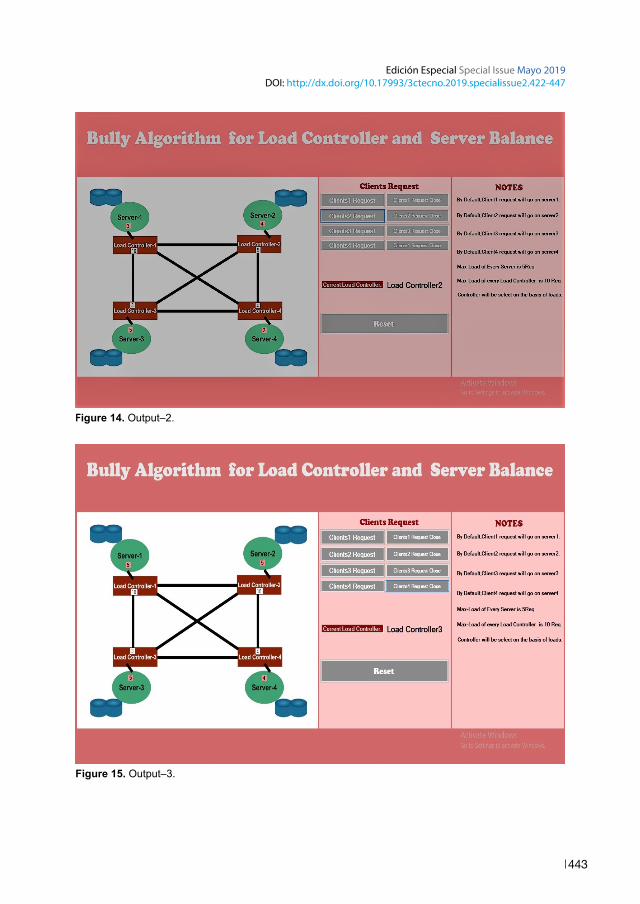
Figure 14. Output–2.
Figure 15. Output–3.

3C Tecnología. Glosas de innovación aplicadas a la pyme. ISSN: 2254–4143
444
Pseudo Code of Load Controller:
int LoadController1=0;int LoadController1=1;int LoadController1=2;int LoadController1=3;void Controller Selection() { If (LoadController1 < LoadController2 && LoadController1 < LoadController3 && LoadController1 < LoadController4 || LoadController1 < 10) { LoadController1++;LCSelect.Text = “Load Controller1”; }else {if ( LoadController2 < LoadController3 && LoadController2 <LoadController3 && LoadController2 < LoadController4 || LoadController2 <10) {LoadController2++;LCSelect.Text = “Load Controller2”; }else {if ( LoadController3 < LoadController4 || LoadController3 < 10) {LoadController3++;LCSelect.Text = “Load Controller3 }else {

Edición Especial Special Issue Mayo 2019DOI: http://dx.doi.org/10.17993/3ctecno.2019.specialissue2.422-447
445
if ( Lo4dController2 < LoadController3 || LoadController4 < 10) {LoadController4++;LCSelect.Text = “Load Controller4”; }else {Message(“Sorry..All Load Controllers are failed..”) } } } } }
8. CONCLUSION AND FUTURE WORKIn this research paper, we discussed how the databases are distributed in different places. The existing research papers show that only one load balancer is available to balance the load. If it fails, the entire system may shut down. To remove this problem every database server has its own balance controller. If one of them fails the others will be activated and it will work as it was working previously. Load balancing technology is necessary today in environments where big data are working. To handle the big data, it is necessary that database servers should be balanced to work properly. To balance the load, the best algorithm is required which takes minimum time complexity.

3C Tecnología. Glosas de innovación aplicadas a la pyme. ISSN: 2254–4143
446
REFERENCESBhat, U. N. (2008). An Introduction to Queueing Theory, Modeling and Analysis in
Applications. Boston, U.S.A.: Birkhauser.
Breitbart, Y., Olson, P. L. & Thompson, G. R. (1986). Database integration in a distributed heterogeneous database system. In IEEE Second International Conference on Data Engineering, pp. 301–310. doi: http://dx.doi.org/10.1109/icde. 1986.7266234
Chen, S., Chen, Y. & Kuo, S. (2017). CLB: A novel load balancing architecture and algorithm for cloud services. Computers & Electrical Engineering, pp. 154–160. doi: http://dx.doi.org/10.1016/j.compeleceng.2016.01.029
Chen, W., Li, H., Ma, Q. & Shang, Z. (2014). Design and implementation of server cluster dynamic load balancing in a virtualization environment based on OpenFlow. Proceedings of The Ninth International Conference on Future Internet Technologies – CFI 14. doi: http://dx.doi.org/10.1145/2619287.2619288
Dhamdhere, D. M. (2012). Operating Systems A Concept–BasedApproach. (3rd ed.). New York, U.S.A.: Mc Graw Hill.
Feng, Y., Li, D., Wu, H. & Zhang, Y. (2000). A dynamic load balancing algorithm based on the distributed database system. Proceedings Fourth International Conference/Exhibition on High–Performance Computing in the Asia–Pacific Region, pp. 949–952. doi: http://dx.doi.org/10.1109/hpc.2000.843577
Hennessy, J. L. (2019). Computer architecture: A quantitative approach. U.S.A.: Morgan Kaufmann.
Kumar, K., Gupta, S. K. & Singh, G. (2014). A Novel Survey on an Intelligent and Efficient Load Balancing Techniques for Cloud Computing. International Journal of Computer Science and Technology, 5(4), pp. 76–80.
Özsu, M. T. & Valduriez, P. (2011). Principles of Distributed Database Systems (3rd ed.). Springer.

Edición Especial Special Issue Mayo 2019DOI: http://dx.doi.org/10.17993/3ctecno.2019.specialissue2.422-447
447
Sadowsky, J. S. & Szpankowski, W. (2009). Maximum Queue Length and Waiting Time Revisited: Multiserver G/G/ c Queue. Probability in the Engineering and Informational Sciences, 6(02), 157. doi: http://dx.doi.org/10.1017/s0269964800002424
Shortle, J. F., Thompson, J. M., Gross, D. & Harris, C. M. (2018). Fundamentals of queueing theory. Hoboken, NJ: Wiley.
Silberschatz, A., Korth, H. F. & Sudarshan, S. (2013). Database System Concepts. Mc Graw Hill.
Tanenbaum, A. S. (2013). Distributed operating systems. Pearson Education.
Tanenbaum, A. S. & Bos, H. (2015). Modern Operating Systems. (4th ed.). Pearson Education.
Tanenbaum, A. S. & Steen, M. V. (2007). Distributed Systems Principle and Paradigm (II ed.). Pearson Education.
Wu, Y. (2011). Computing and Intelligent Systems. In Communications in Computer and Information Science, 1–548. doi: http://dx.doi.org/10.1007/978–3–642–24010–2
Xu, G., Pang, J. & Fu, X. (2013). A load balancing model based on cloud partitioning for the public cloud. Tsinghua Science and Technology, 18(1), pp. 34–39. doi: http://dx.doi.org/10.1109/tst.2013.6449405
Zuikevičiūtė, V. & Pedone, F. (2008). Conflict–aware load–balancing techniques for database replication. Proceedings of the 2008 ACM Symposium on Applied Computing – SAC 08. doi: http://dx.doi.org/10.1145/1363686.1364205


![Memory & Processor Buskoopman/lectures/ece348/08_bus_memo… · DRAM Read Cycle [18-240] ... register, load latches, write memory)! Row Address valid. Load row-address register, read](https://img.dokumen.tips/doc/110x75/5e8e5e1d8678b076c97fc775/memory-processor-bus-koopmanlecturesece34808busmemo-dram-read-cycle.jpg)