Embed Size (px)
Citation preview

Installation and Operation Manual
Load Sharing Module
Analog Output 9907-173
Manual 26011 (Revision C)

WARNING—DANGER OF DEATH OR PERSONAL INJURY
WARNING—FOLLOW INSTRUCTIONS Read this entire manual and all other publications pertaining to the work to be performed before installing, operating, or servicing this equipment. Practice all plant and safety instructions and precautions. Failure to follow instructions can cause personal injury and/or property damage.
WARNING—OUT-OF-DATE PUBLICATION This publication may have been revised or updated since this copy was produced. To verify that you have the latest revision, be sure to check the Woodward website:
www.woodward.com/pubs/current.pdf The revision level is shown at the bottom of the front cover after the publication number. The latest version of most publications is available at:
www.woodward.com/publications If your publication is not there, please contact your customer service representative to get the latest copy.
WARNING—OVERSPEED PROTECTION The engine, turbine, or other type of prime mover should be equipped with an overspeed shutdown device to protect against runaway or damage to the prime mover with possible personal injury, loss of life, or property damage. The overspeed shutdown device must be totally independent of the prime mover control system. An overtemperature or overpressure shutdown device may also be needed for safety, as appropriate.
WARNING—PROPER USE Any unauthorized modifications to or use of this equipment outside its specified mechanical, electrical, or other operating limits may cause personal injury and/or property damage, including damage to the equipment. Any such unauthorized modifications: (i) constitute "misuse" and/or "negligence" within the meaning of the product warranty thereby excluding warranty coverage for any resulting damage, and (ii) invalidate product certifications or listings.
CAUTION—POSSIBLE DAMAGE TO EQUIPMENT OR PROPERTY
CAUTION—BATTERY CHARGING To prevent damage to a control system that uses an alternator or battery-charging device, make sure the charging device is turned off before disconnecting the battery from the system.
CAUTION—ELECTROSTATIC DISCHARGE Electronic controls contain static-sensitive parts. Observe the following precautions to prevent damage to these parts. • Discharge body static before handling the control (with power to the control turned off,
contact a grounded surface and maintain contact while handling the control). • Avoid all plastic, vinyl, and Styrofoam (except antistatic versions) around printed circuit
boards. • Do not touch the components or conductors on a printed circuit board with your hands
or with conductive devices.
IMPORTANT DEFINITIONS • A WARNING indicates a potentially hazardous situation which, if not avoided, could result in
death or serious injury. • A CAUTION indicates a potentially hazardous situation which, if not avoided, could result in
damage to equipment or property. • A NOTE provides other helpful information that does not fall under the warning or caution
categories. Revisions—Text changes are indicated by a black line alongside the text. Woodward Governor Company reserves the right to update any portion of this publication at any time. Information provided by Woodward Governor Company is believed to be correct and reliable. However, no responsibility is assumed by Woodward Governor Company unless otherwise expressly undertaken.
© Woodward 1999 All Rights Reserved
Manual 26011 Load Sharing Module
Woodward i
Contents
CHAPTER 1. GENERAL INFORMATION........................................................... 1 Introduction.............................................................................................................1 Description..............................................................................................................1 CHAPTER 2. ELECTROSTATIC DISCHARGE AWARENESS............................... 5 CHAPTER 3. INSTALLATION.......................................................................... 6 Introduction.............................................................................................................6 Unpacking...............................................................................................................6 Location Considerations.........................................................................................6 General Wiring Requirements ................................................................................7 Power Requirements..............................................................................................7 Shielded Wiring ......................................................................................................8 Generator Connections ..........................................................................................9 Current Transformers .............................................................................................9 Load Sharing Lines, Droop, and Auxiliary Contacts ..............................................9 Output to the Engine Speed Control ....................................................................10 Synchronization Connections...............................................................................10 CHAPTER 4. SETUP AND CALIBRATION ...................................................... 11 Introduction...........................................................................................................11 Phasing Check .....................................................................................................12 Phase Correction Procedure ................................................................................13 Load Gain Adjustment ..........................................................................................17 Droop Adjustment.................................................................................................17 Setting Droop for an Isolated Load.......................................................................17 Setting Droop for an Infinite Bus ..........................................................................18 CHAPTER 5. THEORY OF OPERATION......................................................... 19 Introduction...........................................................................................................19 Power Supply .......................................................................................................19 Power Sensor .......................................................................................................19 Load Comparator Circuit ......................................................................................19 Isochronous Load Sharing ...................................................................................20 Droop Operation ...................................................................................................20 Auxiliary Equipment..............................................................................................20 CHAPTER 6. TROUBLESHOOTING............................................................... 21 CHAPTER 7. SERVICE OPTIONS ................................................................. 23 Product Service Options.......................................................................................23 Returning Equipment for Repair...........................................................................24 Replacement Parts ...............................................................................................25 How to Contact Woodward...................................................................................25 Engineering Services ...........................................................................................26 Technical Assistance............................................................................................27 APPENDIX. LSM CONTROL SPECIFICATIONS.............................................. 28 DECLARATIONS......................................................................................... 31

Load Sharing Module Manual 26011
ii Woodward
Illustrations and Tables Figure 1-1. Typical System Using a Load Sharing Module....................................1 Figure 1-2. Outline Drawing of Load Sharing Module ............................................2 Figure 1-3. Plant Wiring Diagram of Load Sharing Module ...................................3 Figure 1-4. Block Diagram of Load Sharing Module ..............................................4 Figure 3-1. Preparation of Shielded Cables ...........................................................8 Figure 4-1. Temporary CT Connections...............................................................14 Figure 4-2. Droop Adjustment ..............................................................................18

Manual 26011 Load Sharing Module
Woodward 1
Chapter 1. General Information
Introduction The Woodward Load Sharing Module is made for use with engines equipped with speed controls that accept a ±3 Vdc speed setting. The Load Sharing Module allows use of Woodward power generation accessories and allows load sharing between engines equipped with speed controls that are not manufactured by Woodward and engines controlled with Woodward electronic controls, or controls using other Woodward load sharing modules.
Description The Load Sharing Module provides isochronous and droop load-sharing capability for engines in generator set applications. Additional equipment in the control system can include the Woodward SPM-A Synchronizer, Paralleling Phase Switch, Import/Export Control, Precision Frequency Control, Automatic Generator Loading Control, and Automatic Power Transfer and Loading Control. Figure 1-1 shows a typical system using a Load Sharing Module.
Figure 1-1. Typical System Using a Load Sharing Module

Load Sharing Module Manual 26011
2 Woodward
Figure 1-2. Outline Drawing of Load Sharing Module

Manual 26011 Load Sharing Module
Woodward 3
Figure 1-3. Plant Wiring Diagram of Load Sharing Module

Load Sharing Module Manual 26011
4 Woodward
Figure 1-4. Block Diagram of Load Sharing Module

Manual 26011 Load Sharing Module
Woodward 5
Chapter 2. Electrostatic Discharge Awareness
All electronic equipment is static-sensitive, some components more than others. To protect these components from static damage, you must take special precautions to minimize or eliminate electrostatic discharges.
CAUTION—DO NOT SERVICE To prevent possible serious damage to the Load Sharing Module, do not attempt to service the unit beyond that described in the operating instructions. All other servicing should be referred to qualified service personnel. Follow these precautions when working with or near the control. 1. Before doing maintenance on the electronic control, discharge the static
electricity on your body to ground by touching and holding a grounded metal object (pipes, cabinets, equipment, etc.).
2. Avoid the build-up of static electricity on your body by not wearing clothing
made of synthetic materials. Wear cotton or cotton-blend materials as much as possible because these do not store static electric charges as much as synthetics.
3. Keep plastic, vinyl, and Styrofoam materials (such as plastic or Styrofoam
cups, cup holders, cigarette packages, cellophane wrappers, vinyl books or folders, plastic bottles, and plastic ash trays) away from the control, the modules, and the work area as much as possible.
4. Do not remove the printed circuit board (PCB) from the control cabinet
unless absolutely necessary. If you must remove the PCB from the control cabinet, follow these precautions:
• Do not touch any part of the PCB except the edges. • Do not touch the electrical conductors, the connectors, or the
components with conductive devices or with your hands. • When replacing a PCB, keep the new PCB in the plastic antistatic
protective bag it comes in until you are ready to install it. Immediately after removing the old PCB from the control cabinet, place it in the antistatic protective bag.
CAUTION—ELECTROSTATIC DISCHARGE To prevent damage to electronic components caused by improper handling, read and observe the precautions in Woodward manual 82715, Guide for Handling and Protection of Electronic Controls, Printed Circuit Boards, and Modules.

Load Sharing Module Manual 26011
6 Woodward
Chapter 3. Installation
Introduction This section contains general installation instructions for the Load Sharing Module. Environmental precautions and location considerations are included to determine the best location for the Load Sharing Module. Additional information includes unpacking instructions, electrical connections, and an installation check-out procedure.
Unpacking Before handling the Load Sharing Module, read Chapter 2, Electrostatic Discharge Awareness. Be careful when unpacking the Load Sharing Module. Check the unit for signs of damage such as bent or dented panels, scratches, and loose or broken parts. Notify the shipper of any damage.
Location Considerations Consider these requirements when selecting the mounting location: • Adequate ventilation for cooling • Space for servicing and repair • Protection from direct exposure to water or to a condensation-prone
environment • Protection from high-voltage or high-current devices, or devices which
produce electromagnetic interference • Protection from excessive vibration • An ambient operating temperature range of –40 to +70 °C (–40 to +158 °F) Do not mount the Load Sharing Module on the engine. Figure 1-2 is an outline drawing of the Load Sharing Module. Install the unit as close as practical to the electronic engine control, but not on the engine itself. It may be installed in any position. To maintain compliance with CE marking requirements, the European Union Low Voltage Directive requires that the Load Sharing Module (LSM) be mounted in an IP43 enclosure as defined in EN60529. Access to the Load Sharing Module must be restricted to qualified personnel.

Manual 26011 Load Sharing Module
Woodward 7
General Wiring Requirements
The circled ground symbol identifies the Protective Earth Terminal. This terminal must be connected directly to protective earth using a grounding conductor at least as large as those used on terminals 1 through 9. The insulation of the grounding conductor must be of green and yellow color.
This symbol identifies functional or EMC earth. This terminal is to be used for cable shield connections only. It is not to be used as a protective earth terminal.
External wiring connections and shielding requirements for a typical installation are shown in the plant wiring diagram, Figure 1-3. These wiring connections and shielding requirements are explained in more detail in this chapter. To maintain compliance with CE marking requirements, the Low Voltage Directive requires that the Load Sharing Module must only be connected to Class III equipment. Wiring for the Load Sharing Module must be suitable for at least 90 °C (194 °F) and also be suitable for the maximum installed operating temperature. The Load Sharing Module must be permanently connected and employ fuses or circuit breakers in each of the PT lines to limit current to the LSM PT inputs to no more than 5 A. All terminal block screws must be tightened to 0.56 to 0.79 N·m (5.0 to 7.0 lb-in). To maintain compliance with CE marking requirements, the EMC Directive requires that all shields be connected to the terminals provided per the plant wiring diagram, Figure 1-3.
Power Requirements The Load Sharing Module is powered from the potential transformer connections. Jumpers are used to set the module for the voltage being produced by the generator. Jumper terminals 15 to 16 and 17 to 18 when the generator is producing 95 to 130 Vac. Jumper terminal 16 to 17 when the generator is producing 190 to 260 Vac. Potential transformer burden is 1.6 W per phase with 230 Vac input and 0.4 W per phase with 115 Vac input.
CAUTION—JUMPERS ONLY Make only jumper connections to terminals 15 through 18. DO NOT MAKE ANY ELECTRICAL CONNECTIONS to these terminals. The unit is shipped with terminals 15–16 and 17–18 jumpered for 95 to 130 volt generation. To change to 190–260 volt generation, remove both jumpers and install one of the jumpers across terminals 16–17. The other jumper is then not used.

Load Sharing Module Manual 26011
8 Woodward
Shielded Wiring All shielded cable must be twisted conductors with either a foil or braided shield. Do not attempt to tin (put solder on) the braided shield. All signal lines should be shielded to prevent picking up stray signals from adjacent equipment. Connect the shields to the terminals indicated in the plant wiring diagram. Wire exposed beyond the shield must be as short as possible. The other end of the shields must be left open and insulated from any other conductor. Do not run shielded signal wires with other wires carrying large currents. See Application Note 50532, EMI Control for Electronic Governing Systems, for more information. Where shielded cable is required, cut the cable to the desired length and prepare the cable as instructed below and shown in Figure 3-1.
Figure 3-1. Preparation of Shielded Cables 1. Strip outer insulation from both ends, exposing the braided or spiral wrapped
shield. Do not cut the shield on the end nearest to the Load Sharing Module. Cut off the shield on the end away from the unit.
2. Use a sharp, pointed tool to carefully spread the strands of the shield. 3. Pull the inner conductors out of the shield. Twist braided shields to prevent
fraying. 4. Connect lugs to the shield and to the control wires. Number 6 slotted or
round crimp-on terminals are used for most installations. Connect the wires to the appropriate terminals on the module.
Installations with severe electromagnetic interference (EMI) may require shielded wire run in conduit, double shielded wire, or other precautions.
Manual 26011 Load Sharing Module
Woodward 9
Generator Connections
NOTE Use 1 mm² (18 AWG) or larger wire for all PT and CT connections. The spacing between the lugs on terminals 3 and 4 must be 6.5 mm (0.256 inch) or greater to comply with the European Union Low Voltage Directive (see Figure 1-3). The lugs must have insulated sleeves.
IMPORTANT Connections from the potential transformers and current transformers must be made correctly in regard to the three phases for the Load Sharing Module to operate correctly. Sorting out the three phases at the module is tedious and requires numerous generator starts and stops. If at all possible, make sure that the wiring is correctly done at the time of installation and the phases correctly and permanently identified at the generator and at the module. Connect the PT output from the A leg to terminal 1. Connect the PT output from the B leg to terminal 2. Connect the PT output from the C leg to terminal 3. Size the potential transformers to produce 100–240 Vac.
Current Transformers Power source current transformers should be sized to produce 5 A secondary current with maximum generator current (3–7 A secondary current at full load is acceptable). CT burden is 0.1 VA. To prevent lethal high voltage from developing on leads to the terminals, the Load Sharing Module contains internal burden which must be connected across the power source current transformers whenever the unit is running. Ammeters may be installed on the leads from the current transformers. Connect phase “A” CT to terminals 4 and 5. Connect phase “B” CT to terminals 6 and 7. Connect Phase “C” CT to terminals 8 and 9. Observe correct phasing as shown in the plant wiring diagram, Figure 1-3.
Load Sharing Lines, Droop, and Auxiliary Contacts The droop contact for selecting droop or isochronous operation is wired in series with the circuit breaker auxiliary contact between terminals 13 and 14. When both the droop contact and circuit breaker auxiliary contact are closed, the Load Sharing Module is in the isochronous load sharing mode. In this mode the internal load-sharing-line relay is energized, the droop signal is disabled, and the load matching circuit is connected to the load-sharing lines, permitting isochronous load sharing. The Load Sharing Module is in the droop mode when EITHER the droop contact or the circuit breaker auxiliary contact is open. If the droop contact is open, the Load Sharing Module remains in the droop mode even when the circuit breaker auxiliary contact is closed. If droop is not desired when the auxiliary contact is open, turn the droop potentiometer fully counterclockwise. Use a single pole, single-throw switch with a 0.1 A minimum rating for the “open for droop” switch.

Load Sharing Module Manual 26011
10 Woodward
Output to the Engine Speed Control Use twisted 0.5 mm² (20 AWG) or larger shielded wire to connect the output signal from terminals 19, 20, and 21 to the engine speed control. Connect the shield to the closest chassis screw only. Do not connect the shield at the speed control end of the wiring.
Synchronization Connections If an SPM-A synchronizer is used, connect twisted-pair 0.5 mm² (20 AWG) or larger shielded wire from the synchronizer to terminals 24(+) and 25(–). Tie the shield to the closest chassis screw. Do not connect the shield at the synchronizer end of the wiring.

Manual 26011 Load Sharing Module
Woodward 11
Chapter 4. Setup and Calibration
Introduction Use this calibration procedure after a Load Sharing Module is installed on a generator set, to obtain the needed operating characteristics during load sharing. 1. Check that the correct jumpers are installed on terminals 15, 16, 17, and 18
to match your potential transformer secondary voltage. See the plant wiring diagram (Figure 1-3).
2. Remove wires from load sharing line terminals 10 and 11, and from the
SPM-A Synchronizer (if used) at terminals 24 and 25. 3. Select isochronous operation by shorting terminals 13 and 14.
WARNING—START-UP Be prepared to make an emergency shutdown when starting the engine, turbine, or other type of prime mover, to protect against runaway or overspeed with possible personal injury, loss of life, or property damage. 4. Start the engine according to the engine manufacturer’s instructions. Adjust
the engine for rated speed. Apply full load to the generator set.
NOTE The most accurate calibration is made at full load. However, if it is not possible to run the generator set at full load, run it at less than full load, and reduce the voltage readings given in this calibration procedure proportionally. For example: run a 200 kW generator set at 100 kW and divide all voltages given in this calibration procedure by 2. If you reduce the load in this manner, be sure to reduce it by the same amount throughout the calibration procedure. 5. Set the LOAD GAIN potentiometer fully clockwise. 6. Check the load signal voltage between terminals 22 and 23. Adjust the
LOAD GAIN potentiometer for 6.0 Vdc signal. If this voltage is not obtainable, set the load signal as close as possible to 6 Vdc.
7. Remove the load from the generator set. 8. Check the voltage between terminals 22 and 23. This voltage should be 0.0
± 0.25 Vdc. If this voltage is not correct, the Load Sharing Module is faulty or there may still be load on the generator.

Load Sharing Module Manual 26011
12 Woodward
Phasing Check
WARNING—HIGH VOLTAGE A high voltage across open CTs (current transformers) can cause death or serious injury. Do not disconnect a CT from the Load Sharing Module while the engine is running. The CTs can develop dangerously high voltages and may explode if open circuited while the engine is running. For this check, the generator set must be running isochronously, not paralleled, and with a power factor greater than 0.8. 9. Check that the potential connections are made as follows and correct them
if they are not. • Phase A to terminal 1 • Phase B to Terminal 2 • Phase C to Terminal 3
NOTE The most accurate calibration is made at full load. However, if it is not possible to run the generator set at full load, run it at less than full load, and reduce the voltage readings given in this calibration procedure proportionally. For example: run a 200 kW generator set at 100 kW and divide all voltages given in this calibration procedure by 2. If you reduce the load in this manner, be sure to reduce it the same amount throughout this calibration procedure. 10. Start the engine and apply full load to the generator set. 11. Using a dc voltmeter, measure the load signal at terminals 22 and 23.
Adjust the load gain potentiometer to give a 6 Vdc load signal. If 6 Vdc is not obtainable, set the load signal as close as possible to 6 Vdc. Record this voltage.
12. Shut down the generator set.
WARNING—HIGH VOLTAGE A high voltage across open CTs (current transformers) can cause death or serious injury. Do not disconnect a CT from the Load Sharing Module while the engine is running. The CTs can develop dangerously high voltages and may explode if open circuited while the engine is running. 13. Disconnect the wire from terminal 5 that comes from the phase “A” CT and
connect both wires from this CT to terminal 4. 14. Start the generator set and apply full load. 15. Measure the load signal at terminals 22 and 23. If the phase “B” and “C”
current transformers are connected correctly, this voltage will be 1/3 lower than the voltage recorded in step 13. For example: if the reading was 6 volts in step 13, the reading in this step should be approximately 4 volts.
16. Shut down the generator set. 17. Reconnect the phase “A” CT wire to terminal 5. 18. If the reading in step 15 was correct, proceed to Load Gain Adjustment later
in this chapter. Otherwise, perform the following Phase Correction Procedure.

Manual 26011 Load Sharing Module
Woodward 13
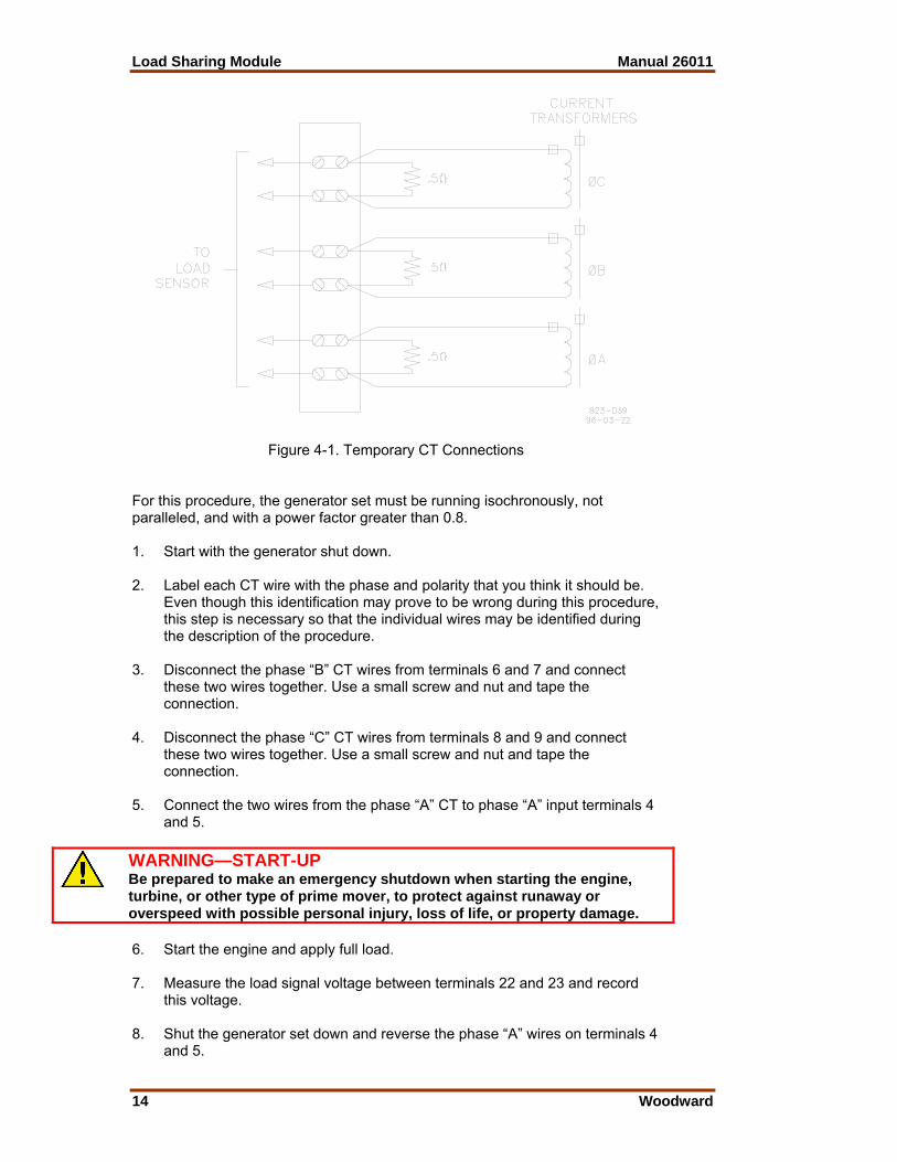
Phase Correction Procedure If this procedure is followed, the correct connection of the current transformers is assured; the correct CT will be connected to the correct input on the Load Sharing Module with the correct polarity. Use this procedure only if the Phasing Check indicates that the phasing is incorrect. A CT for any phase (A, B, or C), will produce the most positive load signal voltage when it is connected, in the proper polarity, to the terminals on the Load Sharing Module which correspond to the same phase. Any other connections of this CT will produce a less positive load signal voltage. This procedure makes trial connections of the first CT to all three CT inputs on the Load Sharing Module, polarized both ways on each CT input. The load signal voltage is recorded for each connection, and the CT is then connected to the CT input terminals that produced the most positive load signal voltage and with the polarity that produced the most positive load signal voltage. In a like manner, the second CT is tried on each of the two remaining CT input terminals in each polarity, then connected, in the correct polarity, to the terminals which produced the most positive load signal voltage. The remaining CT is then connected to the remaining CT input and the load signal checked for each polarity. This CT is then connected to the CT input, polarized so that it produces the most positive load signal voltage. When the procedure is completed, all three CTs are connected to the proper CT inputs on the Load Sharing Module, with the correct polarity, and are now labeled with their correct designations. The procedure for correcting phase wiring requires that the generator set be shut down and the current transformers disconnected many times. For convenience during the phasing check, the temporary method of connecting the current transformers shown in Figure 4-1 is recommended. By connecting a burden resistor (a 0.5 Ω, 20 W resistor), across each current transformer, that current transformer can be disconnected from the Load Sharing Module after removing all load. The connections between the terminal strip and the Load Sharing Module can be changed with the generator set running; however, remove all load before any changes in connections are made. Do not disconnect a wire from a current transformer with load on the system. After completion of the procedure remove the terminal strip and the resistors.
WARNING—HIGH VOLTAGE A high voltage across open CTs (current transformers) can cause death or serious injury. Do not disconnect a CT from the Load Sharing Module while the engine is running. The CTs can develop dangerously high voltages and may explode if open circuited while the engine is running.
Load Sharing Module Manual 26011
14 Woodward
Figure 4-1. Temporary CT Connections For this procedure, the generator set must be running isochronously, not paralleled, and with a power factor greater than 0.8. 1. Start with the generator shut down. 2. Label each CT wire with the phase and polarity that you think it should be.
Even though this identification may prove to be wrong during this procedure, this step is necessary so that the individual wires may be identified during the description of the procedure.
3. Disconnect the phase “B” CT wires from terminals 6 and 7 and connect
these two wires together. Use a small screw and nut and tape the connection.
4. Disconnect the phase “C” CT wires from terminals 8 and 9 and connect
these two wires together. Use a small screw and nut and tape the connection.
5. Connect the two wires from the phase “A” CT to phase “A” input terminals 4
and 5.
WARNING—START-UP Be prepared to make an emergency shutdown when starting the engine, turbine, or other type of prime mover, to protect against runaway or overspeed with possible personal injury, loss of life, or property damage. 6. Start the engine and apply full load. 7. Measure the load signal voltage between terminals 22 and 23 and record
this voltage. 8. Shut the generator set down and reverse the phase “A” wires on terminals 4
and 5.

Manual 26011 Load Sharing Module
Woodward 15
9. Start the engine and apply full load. 10. Measure the load signal voltage between terminals 22 and 23 and record
this voltage. 11. Shut the generator set down. 12. Remove the phase “A” CT wires from terminal 4 and 5 and connect the
phase “A” CT wires to the phase “B” input terminals 6 and 7. 13. Start the engine and apply full load. 14. Measure the load signal voltage between terminals 22 and 23 and record
this voltage. 15. Shut the generator set down and reverse the phase “A” CT wires on
terminals 6 and 7. 16. Start the engine and apply full load. 17. Measure the load signal voltage between terminals 22 and 23 and record
this voltage. 18. Shut down the generator set. 19. Remove the phase “A” CT wires from terminal 6 and 7 and connect the
phase “A” CT wires to the phase “C” input terminals 8 and 9. 20. Start the engine and apply full load. 21. Measure the load signal voltage between terminals 22 and 23 and record
this voltage. 22. Shut the generator set down and reverse the phase “A” wires on terminals 8
and 9. 23. Start the engine and apply full load. 24. Measure the load signal voltage between terminals 22 and 23 and record
this voltage. 25. Shut down the generator set. 26. Remove the phase “A” CT wires from terminal 8 and 9 and connect the
wires to the pair of terminals, in the same polarity, that produced the most positive load signal voltage.
27. Untape and disconnect the Phase “B” CT wires. Connect the phase “B” CT
wires to one pair of the two remaining CT input terminals on the Load Sharing Module.
28. Start the generator set and apply full load. 29. Measure the load signal voltage at terminals 22 and 23 and record this
voltage. 30. Shut the generator set down and reverse the phase “B” wires on the CT
input terminals.

Load Sharing Module Manual 26011
16 Woodward
31. Start the engine and apply full load. 32. Measure the load signal voltage between terminals 22 and 23 and record
this voltage. 33. Shut down the generator set. 34. Remove the phase “B” CT wires from the terminals they are connected to
and connect them to the remaining pair of CT input terminals on the Load Sharing Module.
35. Start the generator set and apply full load. 36. Measure the load signal at terminals 22 and 23 and record this voltage. 37. Shut the generator set down and reverse the phase “B” wires on the CT
input terminals. 38. Start the engine and apply full load. 39. Measure the load signal voltage between terminals 22 and 23 and record
this voltage. 40. Shut down the generator set. 41. Remove the phase “B” CT wires from the CT input terminals and connect
the wires to the pair of terminals, in the same polarity, that produced the most positive load signal voltage.
42. Untape and disconnect the Phase “C” CT wires. Connect the phase “C” CT
wires to remaining pair of CT input terminals on the Load Sharing Module. 43. Start the generator set and apply full load. 44. Measure the load signal voltage at terminals 22 and 23 and record this
voltage. 45. Shut the generator set down and reverse the phase “C” wires on the CT
input terminals. 46. Start the engine and apply full load. 47. Measure the load signal voltage between terminals 22 and 23 and record
this voltage. 48. Shut down the generator set. 49. Remove the phase “C” CT wires from the CT input terminals and connect
the wires to the pair of terminals, in the same polarity that produced the most positive load signal voltage.
50. Label each wire with the designation of the terminal to which it is now
connected. Be sure and remove the original designations to avoid future confusion.

Manual 26011 Load Sharing Module
Woodward 17
Load Gain Adjustment For this procedure, the generator set must be running isochronously, not paralleled, and with a power factor greater than 0.8. 1. Start the generator set and run at full load. 2. Measure the load signal voltage and adjust the LOAD GAIN potentiometer
for 6 ± 0.1 Vdc. If the load signal voltage cannot be raised to 6 volts, and the phasing has been checked and is correct, it will be necessary to use a lower load signal voltage. Set the full load signal voltages of all generator sets in the system to the same voltage. When paralleled, adjustment of a generator set's LOAD GAIN potentiometer clockwise will cause that generator set to carry less load. If stability problems occur when paralleled at a particular load signal voltage, reduce the load signal voltage by adjusting the LOAD GAIN potentiometer counterclockwise and set the load signal voltage of all other generator sets in the system to the same voltage (NOTE—Adjust the LOAD GAIN with the generator running isochronously and not paralleled). When the load signal voltages of all generator sets in a system are reduced, the load sharing gain will be reduced. This may result in some loss of load-sharing sensitivity but will increase load sharing stability. It may be necessary to reduce the load signal voltage of each unit in the system to as low as three volts in cases of extremely poor system dynamics.
Droop Adjustment Droop is usually expressed as a percentage. Droop percentage is calculated by dividing the difference between the no load speed and the full load speed by the rated speed. The DROOP potentiometer only needs to be adjusted when the generator set is to be operated in droop mode. The method of setting droop depends on whether the load on the generator set is an isolated load or an infinite bus. Once adjusted, the droop potentiometer will not have to be readjusted unless a different droop percentage is desired.
Setting Droop for an Isolated Load 1. Open the OPEN FOR DROOP switch (or disconnect the wires from
terminals 13 and 14). 2. Start the engine and adjust the speed for rated with no load. 3. Apply full load. 4. Adjust the DROOP potentiometer to give the desired speed. Example: Operating at 60 Hz, 57 Hz at full load indicates 5 percent droop. If only 50 percent loading is possible, 58.5 Hz would indicate 5 percent
droop (see Figure 4-2).

Load Sharing Module Manual 26011
18 Woodward
Figure 4-2. Droop Adjustment
Setting Droop for an Infinite Bus 1. With the generator not paralleled, adjust the speed above rated frequency
by the percent droop required (set engine at 63 Hz for 5 percent droop on a 60 Hz system).
2. Mark the speed setting potentiometer position or measure dc voltage on
TB27(+) and TB26(–), and re-adjust the engine speed for rated frequency. 3. Turn the DROOP potentiometer fully clockwise for maximum droop. 4. Synchronize the generator with the bus and parallel it with the bus. 5. Increase the speed setting potentiometer to the position marked in step 2,
increasing load. 6. Slowly adjust the DROOP potentiometer counterclockwise, decreasing
droop, until 100 percent load is obtained. If it is necessary to set the droop without pulling 100 percent load, set the engine speed accordingly for the desired percent of droop at the load to be pulled. For example: Five percent droop at 50 percent load will require a no load rated speed of 61.5 Hz, not 63 Hz, on a 60 Hz system.

Manual 26011 Load Sharing Module
Woodward 19
Chapter 5. Theory of Operation
Introduction This chapter describes the operation of the Load Sharing Module and its internal circuits. Figure 1-4 is a block diagram of the circuits in the module. The Load Sharing Module senses the power output of a generator and provides a ±3 Vdc signal to the speed control to adjust the power output of the engine-generator set to match the reference power level. The Load Sharing Module can also produce a droop condition (instead of isochronous load-sharing), making it possible to connect the generator set in parallel with either a generator set which is running isochronously, or with an infinite bus.
Power Supply The power supply generates a regulated dc voltage for the operation of the circuits in the Load Sharing Module. The power supply gets its power from two of the three phase-potential connections which are made to the output of the generator set being controlled. Jumper wires on terminals 15 through 18 provide for selection of input voltages of either 95 to 130 Vac or 190 to 260 Vac. The plant wiring diagram (Figure 1-3) shows these connections and jumpers. Do not connect inputs to terminals 15 through 18.
Power Sensor Generator load is measured by the power-sensor circuit of the Load Sharing Module. The power-sensor circuit senses current amplitude, and produces a load signal proportional to the current amplitude times the power factor. The potential input comes from potential transformers (PTs) and the current input comes from the current transformers (CTs). The circuit uses these two inputs to generate a load signal which is then filtered and sent to the controller circuit. The load signal voltage of each generator set will be proportional to the percentage of rated load on the generator set. Ammeters and voltmeters may be driven with the same PT and CT wires.
Load Comparator Circuit In the load comparator circuit, the load signal voltage is balanced with the other generator sets in the system via the load sharing lines. The comparator circuit of each Load Sharing Module includes a load gain potentiometer to adjust each generator set's load signal so that the load signal voltage of each is the same at full load. This compensates for varying CT ratios or different generator set sizes. The load sharing voltage will be one-half the measured voltage of the load signal test point.

Load Sharing Module Manual 26011
20 Woodward
Isochronous Load Sharing Each comparator circuit compares the load signal voltage for its generator set to two times the voltage on the load sharing lines and produces an error voltage proportional to the difference. This error voltage is used to generate a pulse width modulated signal which is output to the speed control. This output biases the speed loop of the speed control until the load signal voltage is equal to that of other generators on the load sharing lines.
Droop Operation In droop operation, a portion of the load signal voltage is fed to the controller circuit. This voltage is used by the comparator circuit to reduce the control output by a percentage determined by the DROOP potentiometer. The output is reduced, and the speed control reduces engine power output according to the desired droop percentage. When a generator set using the Load Sharing Module is paralleled in droop with other generator sets, the common load signal on the paralleling lines is not used. The frequency of the generator set will therefore vary with load, so it must be determined by a different means. In an isolated system with two or more generator sets paralleled, if isochronous speed control is required, one of the generator sets must be running in the isochronous (constant speed) mode. This generator set maintains the frequency of the system. If a generator set is in droop and is paralleled with an infinite bus, the bus determines and maintains the frequency. The DROOP percentage and the speed setting on the engine speed control determine the amount of the load that is carried by the generator, when running in droop.
Auxiliary Equipment The Woodward SPM-A synchronizer functions by biasing the output of the Load Sharing Module. All other Woodward auxiliary generating control equipment functions by biasing the voltage on the load-sharing lines.

Manual 26011 Load Sharing Module
Woodward 21
Chapter 6. Troubleshooting
The following trouble-shooting guide is an aid in isolating trouble to the Load Sharing Module, engine control, plant wiring, or elsewhere. The guide assumes that the system wiring, soldered connections, switch and relay contacts, and input and output connections are correct and in good working order. Make the checks in the order indicated.
CAUTION—DO NOT SERVICE To prevent possible serious damage to the Load Sharing Module, do not attempt to service the unit beyond that described in the operating instructions. All other servicing should be referred to qualified service personnel.
SYMPTOMS CAUSE TEST/REMEDY Undesirable speed decrease with load increase.
Droop mode switch is open or auxiliary contact is open. Load Sharing Module is in droop mode.
Jumper Load Sharing Module terminals 13 and 14. If this corrects the problem, replace wiring or switch as required. The module will not go into droop with the terminals connected.
Improper engine operation. Operate the engine and observe speed while applying load.
If droop occurs near the full load point only, it is possible the engine is not producing the horsepower called for or is being overloaded.
Faulty engine control. Disconnect the Load Sharing Module and load the engine as a single, isolated unit.
If speed continues to decrease with load, engine operation may be faulty.
Erratic Load Sharing Module operation.
Open or intermittent wire.
Check all wiring for continuity and tight connections. Repair if necessary.
EMI (Electromagnetic Interference).
Remove ground loops. Shield all wiring (load sharing lines, output to the speed control, speed trim pot, and SPM-A synchronizer input. Route wiring away from noise sources.
Unstable system. Check system for proper operation.
Unstable voltage regulator.
Consult voltage regulator manufacturer’s manual for proper adjustment.
Poor system stability. Reduce the load signal voltage of each unit in the system to three volts.
Load Signal voltage is low. Adjusting LOAD Gain won't raise it.
Incorrect phasing of CT and PT wiring.
Perform phasing check. If phasing check indicates need, perform procedure for correct phase wiring.
Insufficient CT output. Check for 5 amp CT output at full load. Change to a lower primary current CT if necessary.

Load Sharing Module Manual 26011
22 Woodward
SYMPTOMS CAUSE TEST/REMEDY Load Signal voltage is too high. Adjusting LOAD GAIN will not lower it.
CT output too high. Check for 5 amp CT output at full load. (CT output must be between 3 and 7 amps at full load.) Change to a higher primary current CT if necessary.
Engine does not properly share load with other units.
Engine not responding to signal from Load Sharing Module.
Check for maximum voltage from terminals 22 to 23. If possible check the voltage from terminal 20 to 19. If the Load Sharing Module is putting out a maximum signal, the problem is either in the wiring to the engine control, the engine control, or the engine.
Unequal speed settings.
Be sure the speed settings of all off-line units at no load are identical. Adjust as necessary. Resynchronize.
Unequal load gain voltages.
Check that load gain settings of all load sharing units are correct. See load gain adjustment in Chapter 4. Adjust as necessary.
Improper load sensing phasing.
Perform the transformer phasing check in Chapter 4. Correct as necessary.
Engine does not properly share load with other units.
Circulating currents between generators. (Noted by unequal power factors between generators.)
Properly adjust the generator voltage regulators.
Engine does not properly share load with other units.
Terminals 13 and 14 not shorted. Load sharing module is in droop.
Jumper Load Sharing Module terminals 13 and 14. Observe engine operation. Replace wiring or switch as required.

Manual 26011 Load Sharing Module
Woodward 23
Chapter 7. Service Options
Product Service Options The following factory options are available for servicing Woodward equipment, based on the standard Woodward Product and Service Warranty (5-01-1205) that is in effect at the time the product is purchased from Woodward or the service is performed: • Replacement/Exchange (24-hour service) • Flat Rate Repair • Flat Rate Remanufacture If you are experiencing problems with installation or unsatisfactory performance of an installed system, the following options are available: • Consult the troubleshooting guide in the manual. • Contact Woodward technical assistance (see “How to Contact Woodward”
later in this chapter) and discuss your problem. In most cases, your problem can be resolved over the phone. If not, you can select which course of action you wish to pursue based on the available services listed in this section.
Replacement/Exchange Replacement/Exchange is a premium program designed for the user who is in need of immediate service. It allows you to request and receive a like-new replacement unit in minimum time (usually within 24 hours of the request), providing a suitable unit is available at the time of the request, thereby minimizing costly downtime. This is also a flat rate structured program and includes the full standard Woodward product warranty (Woodward Product and Service Warranty 5-01-1205). This option allows you to call in the event of an unexpected outage, or in advance of a scheduled outage, to request a replacement control unit. If the unit is available at the time of the call, it can usually be shipped out within 24 hours. You replace your field control unit with the like-new replacement and return the field unit to the Woodward facility as explained below (see “Returning Equipment for Repair” later in this chapter). Charges for the Replacement/Exchange service are based on a flat rate plus shipping expenses. You are invoiced the flat rate replacement/exchange charge plus a core charge at the time the replacement unit is shipped. If the core (field unit) is returned to Woodward within 60 days, Woodward will issue a credit for the core charge. [The core charge is the average difference between the flat rate replacement/exchange charge and the current list price of a new unit.] Return Shipment Authorization Label. To ensure prompt receipt of the core, and avoid additional charges, the package must be properly marked. A return authorization label is included with every Replacement/Exchange unit that leaves Woodward. The core should be repackaged and the return authorization label affixed to the outside of the package. Without the authorization label, receipt of the returned core could be delayed and cause additional charges to be applied.

Load Sharing Module Manual 26011
24 Woodward
Flat Rate Repair Flat Rate Repair is available for the majority of standard products in the field. This program offers you repair service for your products with the advantage of knowing in advance what the cost will be. All repair work carries the standard Woodward service warranty (Woodward Product and Service Warranty 5-01-1205) on replaced parts and labor. Flat Rate Remanufacture Flat Rate Remanufacture is very similar to the Flat Rate Repair option with the exception that the unit will be returned to you in “like-new” condition and carry with it the full standard Woodward product warranty (Woodward Product and Service Warranty 5-01-1205). This option is applicable to mechanical products only.
Returning Equipment for Repair If a control (or any part of an electronic control) is to be returned to Woodward for repair, please contact Woodward in advance to obtain a Return Authorization Number. When shipping the item(s), attach a tag with the following information: • name and location where the control is installed; • name and phone number of contact person; • complete Woodward part number(s) and serial number(s); • description of the problem; • instructions describing the desired type of repair.
CAUTION—ELECTROSTATIC DISCHARGE To prevent damage to electronic components caused by improper handling, read and observe the precautions in Woodward manual 82715, Guide for Handling and Protection of Electronic Controls, Printed Circuit Boards, and Modules. Packing a Control Use the following materials when returning a complete control: • protective caps on any connectors; • antistatic protective bags on all electronic modules; • packing materials that will not damage the surface of the unit; • at least 100 mm (4 inches) of tightly packed, industry-approved packing
material; • a packing carton with double walls; • a strong tape around the outside of the carton for increased strength.

Manual 26011 Load Sharing Module
Woodward 25
Return Authorization Number When returning equipment to Woodward, please telephone and ask for the Customer Service Department [1 (800) 523-2831 in North America or +1 (970) 482-5811]. They will help expedite the processing of your order through our distributors or local service facility. To expedite the repair process, contact Woodward in advance to obtain a Return Authorization Number, and arrange for issue of a purchase order for the item(s) to be repaired. No work can be started until a purchase order is received.
NOTE We highly recommend that you make arrangement in advance for return shipments. Contact a Woodward customer service representative at 1 (800) 523-2831 in North America or +1 (970) 482-5811 for instructions and for a Return Authorization Number.
Replacement Parts When ordering replacement parts for controls, include the following information: • the part number(s) (XXXX-XXXX) that is on the enclosure nameplate; • the unit serial number, which is also on the nameplate.
How to Contact Woodward In North America use the following address when shipping or corresponding: Woodward Governor Company PO Box 1519 1000 East Drake Rd Fort Collins CO 80522-1519, USA Telephone—+1 (970) 482-5811 (24 hours a day) Toll-free Phone (in North America)—1 (800) 523-2831 Fax—+1 (970) 498-3058 For assistance outside North America, call one of the following international Woodward facilities to obtain the address and phone number of the facility nearest your location where you will be able to get information and service. Facility Phone Number Brazil +55 (19) 3708 4800 India +91 (129) 230 7111 Japan +81 (476) 93-4661 The Netherlands +31 (23) 5661111 You can also contact the Woodward Customer Service Department or consult our worldwide directory on Woodward’s website (www.woodward.com) for the name of your nearest Woodward distributor or service facility.

Load Sharing Module Manual 26011
26 Woodward
Engineering Services Woodward Industrial Controls Engineering Services offers the following after-sales support for Woodward products. For these services, you can contact us by telephone, by email, or through the Woodward website. • Technical Support • Product Training • Field Service Contact information: Telephone—+1 (970) 482-5811 Toll-free Phone (in North America)—1 (800) 523-2831 Email—[email protected] Website—www.woodward.com Technical Support is available through our many worldwide locations or our authorized distributors, depending upon the product. This service can assist you with technical questions or problem solving during normal business hours. Emergency assistance is also available during non-business hours by phoning our toll-free number and stating the urgency of your problem. For technical support, please contact us via telephone, email us, or use our website and reference Customer Services and then Technical Support. Product Training is available at many of our worldwide locations (standard classes). We also offer customized classes, which can be tailored to your needs and can be held at one of our locations or at your site. This training, conducted by experienced personnel, will assure that you will be able to maintain system reliability and availability. For information concerning training, please contact us via telephone, email us, or use our website and reference Customer Services and then Product Training. Field Service engineering on-site support is available, depending on the product and location, from one of our many worldwide locations or from one of our authorized distributors. The field engineers are experienced both on Woodward products as well as on much of the non-Woodward equipment with which our products interface. For field service engineering assistance, please contact us via telephone, email us, or use our website and reference Customer Services and then Technical Support.

Manual 26011 Load Sharing Module
Woodward 27
Technical Assistance If you need to telephone for technical assistance, you will need to provide the following information. Please write it down here before phoning: General Your Name Site Location Phone Number Fax Number Prime Mover Information Engine/Turbine Model Number Manufacturer Number of Cylinders (if applicable) Type of Fuel (gas, gaseous, steam, etc) Rating Application Control/Governor Information Please list all Woodward governors, actuators, and electronic controls in your system: Woodward Part Number and Revision Letter Control Description or Governor Type Serial Number Woodward Part Number and Revision Letter Control Description or Governor Type Serial Number Woodward Part Number and Revision Letter Control Description or Governor Type Serial Number If you have an electronic or programmable control, please have the adjustment setting positions or the menu settings written down and with you at the time of the call.

Load Sharing Module Manual 26011
28 Woodward
Appendix. LSM Control Specifications
POWER SUPPLY Power to operate Load Sharing Module circuitry
is obtained from the PT connections. Selectable by jumper for 95 to 130 Vac or 190 to 260 Vac operation. Approximately 10 W.
INPUTS 3-phase PT Inputs 100–120 or 200–240 Vac line-to-line, 50–400
Hz. PT input burden is 1.6 W per phase at 240 Vac, 0.4 W per phase at 120 Vac.
3-phase CT Inputs 3–7 Arms at full load, CT input burden at full
load is 0.1 VA per phase. Load Sharing Input 0–3 Vdc into 25 kΩ impedance in isochronous
mode, open circuit in droop mode. Sync Input Compatible with optional Woodward SPM-A
Synchronizer, 0.5% speed change* per volt input.
Droop SwitchThe external droop switch is to be wired in series with the auxiliary
circuit breaker contact between terminals 13 and 14. Droop mode is selected when either the droop switch or the auxiliary circuit breaker is open.
OUTPUTS Load Signal DC signal proportional to total real current
measured by the Load Sharing Module. Load Gain adjustable over minimum range of 0.86 to 2.0 Vdc/Arms.
Analog Output Minimum dc output range: ±3 Vdc Zero error output = +0.0±0.05 Vdc ADJUSTMENTS Droop Provides 0 to 10% speed reduction* between no
load and full load conditions. Load GainProvides adjustment of the load on an individual generator when two
or more generators are paralleled. Adjusts specified full load condition from 3 to 7 Arms.

Manual 26011 Load Sharing Module
Woodward 29
ENVIRONMENTAL Operating Temperature –40 to +70 °C (–40 to +158 °F). Salt Fog Tested at 5% NaCl, 35 °C, 48 hrs wet, 48 hrs
dry. Humidity Tested at 95% RH, 65 °C, non-condensing, 5
cycles at 24 hr/cycle. Vibration Swept sine: 4 G, 5 mm, 5–2000 Hz, 3 hr
min/axis, including four 30-minute dwells at resonant frequencies.
Shock 40 G, 11 ms sawtooth pulse. Installation Overvoltage Category Category III. Air Quality Pollution Degree 2. DIMENSIONS Linear (maximum) Length: 273.6 mm (10.77 in) Width: 214.1 mm (8.43 in) Height: 59.2 mm (2.33 in) Weight 1488 g (52.5 oz) approximate. SAFETY AND EMC STANDARDS COMPLIANCE Conforms to EMC Directive 89/336/EEC. Conformity established by testing. Conforms to Low Voltage Directive 73/23/EEC when used in accordance with instructions. Conformity established by testing. Listed to UL and cUL Industrial Control Equipment (UL508). *—When used with a speed control having a gain of 3.3% speed change/volt.

Load Sharing Module Manual 26011
30 Woodward

Declarations

We appreciate your comments about the content of our publications.
Send comments to: [email protected]
Please include the manual number from the front cover of this publication.
PO Box 1519, Fort Collins CO 80522-1519, USA 1000 East Drake Road, Fort Collins CO 80525, USA Phone +1 (970) 482-5811 • Fax +1 (970) 498-3058
Email and Website—www.woodward.com
Woodward has company-owned plants, subsidiaries, and branches, as well as authorized distributors and other authorized service and sales facilities throughout the world.
Complete address / phone / fax / email information for all locations is available on our website.
06/5/F