Embed Size (px)
Citation preview
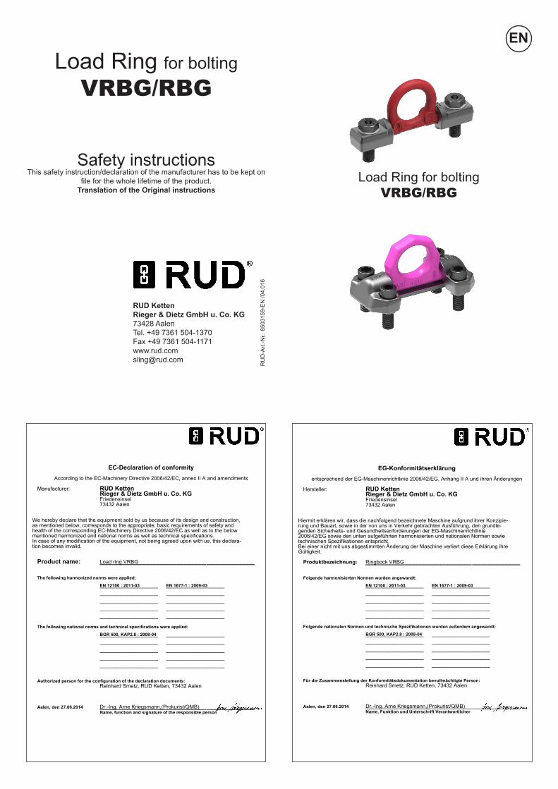
Load Ring for boltingVRBG/RBG
RUD Ketten Rieger & Dietz GmbH u. Co. KG73428 AalenTel. +49 7361 504-1370Fax +49 7361 [email protected]
Load Ring for boltingVRBG/RBG
Safety instructions This safety instruction/declaration of the manufacturer has to be kept on
file for the whole lifetime of the product. Translation of the Original instructions
RU
D-A
rt.-N
r.: 8
5031
59-E
N /0
4.01
6
EN
EC-Declaration of conformityAccording to the EC-Machinery Directive 2006/42/EC, annex II A and amendments
Manufacturer: RUD KettenRieger & Dietz GmbH u. Co. KGFriedensinsel73432 Aalen
We hereby declare that the equipment sold by us because of its design and construction,as mentioned below, corresponds to the appropriate, basic requirements of safety andhealth of the corresponding EC-Machinery Directive 2006/42/EC as well as to the belowmentioned harmonized and national norms as well as technical specifications.In case of any modification of the equipment, not being agreed upon with us, this declara-tion becomes invalid.
Product name: Load ring VRBG__________________________________________________________________________________________
The following harmonized norms were applied:
EN 12100 : 2011-03 EN 1677-1 : 2009-03_________________ __________________________________ __________________________________ __________________________________ __________________________________ _________________
The following national norms and technical specifications were applied:
BGR 500, KAP2.8 : 2008-04_________________ __________________________________ __________________________________ __________________________________ __________________________________ _________________
Authorized person for the configuration of the declaration documents:Reinhard Smetz, RUD Ketten, 73432 Aalen
Aalen, den 27.06.2014 Dr.-Ing. Arne Kriegsmann,(Prokurist/QMB)_____________________________________________Name, function and signature of the responsible person
EG-Konformitätserklärungentsprechend der EG-Maschinenrichtlinie 2006/42/EG, Anhang II A und ihren Änderungen
Hersteller: RUD KettenRieger & Dietz GmbH u. Co. KGFriedensinsel73432 Aalen
Hiermit erklären wir, dass die nachfolgend bezeichnete Maschine aufgrund ihrer Konzipie-rung und Bauart, sowie in der von uns in Verkehr gebrachten Ausführung, den grundle-genden Sicherheits- und Gesundheitsanforderungen der EG-Maschinenrichtlinie2006/42/EG sowie den unten aufgeführten harmonisierten und nationalen Normen sowietechnischen Spezifikationen entspricht.Bei einer nicht mit uns abgestimmten Änderung der Maschine verliert diese Erklärung ihreGültigkeit.
Produktbezeichnung: Ringbock VRBG__________________________________________________________________________________________
Folgende harmonisierten Normen wurden angewandt:
EN 12100 : 2011-03 EN 1677-1 : 2009-03_________________ __________________________________ __________________________________ __________________________________ __________________________________ _________________
Folgende nationalen Normen und technische Spezifikationen wurden außerdem angewandt:
BGR 500, KAP2.8 : 2008-04_________________ __________________________________ __________________________________ __________________________________ __________________________________ _________________
Für die Zusammenstellung der Konformitätsdokumentation bevollmächtigte Person:Reinhard Smetz, RUD Ketten, 73432 Aalen
Aalen, den 27.06.2014 Dr.-Ing. Arne Kriegsmann,(Prokurist/QMB)_____________________________________________Name, Funktion und Unterschrift Verantwortlicher

User Instructions1. Reference should be made to German Standards accord. BGR/DGUV 100-500 or other country specific statutory regulations and inspections are to be carried out by competent persons only.
2. Before installation and every use, visually inspect RUD lifting points, paying particular attention to any evidence of corrosion, wear, weld cracks and deformations. Please ensure compatibility of bolt thread and tapped hole.
3. The material construction to which the lifting point will be attached should be of adequate strength to withstand forces during lifting without deformation. The German testing authoritiy BG, recommends the following minimum for the bolt lengths:
1 x M in steel (min. quality S235JR [1.0037]) 1.25 x M in cast iron (e.g. GG25) 2 x M in aluminium 2,5 x M in aluminium-magnesium alloys (M = thread Ø, e.g. M20)
When lifting light metals, nonferrous metals and cast iron the thread has to be chosen in such a way that the WLL of the th-read corresponds to the requirements of the corresponding base material.
RUD-VRBG/RBG are delivered with 100 % crack tested bolts. Variable bolt length available when using DIN EN ISO 4014 (DIN 931) e.g DIN EN ISO 4762 (DIN 912) bolts. When using your own bolts they have to be 100 % crack tested. You have to use at least a hexagon bolt according to ISO 4014 (DIN 931) with quality 10.9 (for RBG 3) or a hex head bolt accord. ISO 4762 (DIN 912) with quality 12.9 (for VRBG 10 and VRBG 16) with the correct nom. diameter.
4. The lifting points must be positioned to the load in such a way that movements are avoided during lifting. a) For single leg lifts, the lifting point should be vertically above the centre of gravity of the load. b) For two leg lifts, the lifting points must be equidistant to/or above the centre of gravity of the load. c) For three and four leg lifts, the lifting points should be arranged symmetrical around the centre of gravity in the same plane if possible.
5. Load symmetry:The required WLL of the individual RUD lifting point are calculated using the following formula and are based on symmetrical loading:
The calculation of the load bearing legs is a s follows: symmetrical unsymmetrical Two leg 2 1 Three/four leg 3 1 (also refer to table 2 and 3)
6. A plane bolting surface must be guaranteed. The holes must be drilled in the recommended tolerance field and with a suffici-ent depth in order to guarantee compatibility with the supporting surface.
Drilling sequence for the RBG 3: a) Mark the blind hole (Dim F) then drill and countersink the dimen-sions H, G, K. b) After stick in and adjustment the welding blocks the hole for the tapped hole can be drilled.c) The core hole and thread can be machined. For through holes dill only the dimension ”H“.
7. The VRBG/RBG-Ring must be able to pivot 180° after as-sembly. For single use just tighten with spanner. For long term application the VRBG/RBG should be tightened with torque accord. chart 1 (+/- 10 %) inclusive using the locking washer.
8. To prevent unintended dismounting through shock loading, rotation or vibrations thread locking devices are recommended. Therefore different locking systems are possible. Liquid locking fluid such as Loctite (respect manufacturer specifications) or form closed versions such as hex castel nut, counter nut, etc.
9. All fittings connected to the VRBG/RBG should be free moving. When connecting and disconnecting the lifting means (sling chain) pinches and impacts should be avoided. Damage of the lifting means caused by sharp edges should be avoided as well.
10. Effects of temperature: Due to the DIN/EN bolts that are used with the VRBG/RBG the working load limit should be reduced accordingly:
-20° to 100°C no reduction (-4°F to 212°F) 100° to 200°C minus 15 % (212°F to 392°F) 200° to 250°C minus 20 % (392°F to 482°F) 250° to 350°C minus 25 % (482°F to 662°F) Temperatures above 350°C (662°F) are not permitted.
11. RUD lifting points must not be used under chemical influences such as acids, alkaline solutions and vapours e.g. in pickling baths or hot dip galvanising plants. If this cannot avoided, please contact the manufacturer indicating the concentration, period of penetration and temperature of use.
12. The position where the lifting points should be attached should be clearly marked with colour.
13. If the lifting points are used exclusively for lashing, the value of the working load limit can be doubled. LC = 2 x WLL
14. After fitting, an annual inspection or sooner if conditions dic-tate should be undertaken by a competent person examining the continued suitability. Also after damage and special occurrences.
Inspection criteria concerning paragraphs 2 and 14:• Ensure correct bolt size, quality and length• Ensure compatibility of bolt thread and tapped hole• The Lifting point should be complete• Deformations of the components parts such as body fittings and thread• Mechanical damages such as notches, especially in high stress areas.• Wear should be not more than 10 % of cross sectional diameter.• Evidence of corrosion.• Evidence of cracks.• Damage to the bolt and/or thread.
WLL = working load limitG = load weight (kg)n = number of load bearing legsß = angle of inclination of the chain to the vertical
WLL=G
n x cos ß
A non-adherence to this advice may result damages of persons and materials!

Type WLL weight A B C D E F G H I K L M N T screw Torque reference t kg
RBG 3 3 1.07 34 16 5 48 22 92 6 18 30 1 178 16 71 67 ISO 4014 (DIN 931) M16x50-10.9 120 Nm 0051817
VRBG 10 10 6.7 125 22 6 65 143 78 8 30 50 43 213 20 100 102 ISO 4762 (DIN 912) M20x70-12.9 300 Nm 7994537
VRBG 16 16 11.3 170 30 8 90 198 104 10 46 70 63 270 30 134 131 ISO 4762 (DIN 912) M30x90-12.9 600 Nm 7993255
Method of lift
Number of legs 1 1 2 2 2 2 2 3 and 4 3 and 4 3 and 4 Angle of inclination <ß 0° 90° 0° 90° 0-45° 45-60° unsymm. 0-45° 45-60° unsymm. Factor 1 1 2 2 1.4 1 1 2.1 1.5 1
type WLL in metric tonnes
RBG 3 t 3 t 3 t 6 t 6 t 4.2 t 3 t 3 t 6.3 t 4.5 t 3 t
VRBG 10 t 10 t 10 t 20 t 20 t 14.0 t 10 t 10 t 21.0 t 15 t 10 t
VRBG 16 t 16 t 16 t 32 t 32 t 22.4 t 16 t 16 t 33.6 t 24 t 16 tTable 2
RBG 3 VRBG 10VRBG 16
Table 1 Subject to technical alterations
Method of lift
Number of legs 1 1 2 2 2 2 2 3 and 4 3 and 4 3 and 4 Angle of inclination <ß 0° 90° 0° 90° 0-45° 45-60° unsymm. 0-45° 45-60° unsymm. Factor 1 1 2 2 1.4 1 1 2.1 1.5 1
type WLL in lbs
RBG 3 t 6600 lbs 6600 lbs 13200 lbs 13200 lbs 9240 lbs 6600 lbs 6600 lbs 13860 lbs 9900 lbs 6600 lbs
VRBG 10 t 22000 lbs 22000 lbs 44000 lbs 44000 lbs 30800 lbs 22000 lbs 22000 lbs 46200 lbs 33000 lbs 22000 lbs
VRBG 16 t 35200 lbs 35200 lbs 70400 lbs 70400 lbs 49300 lbs 35200 lbs 35200 lbs 74000 lbs 52800 lbs 35200 lbs
Table 3
L
BT
C
D
A
F±0.5
H12H min
.I
Kx4
5°m
in.G
M
E±0.4 N
180° schwenkbar
H12Hmin
.Gm
in.I
+0,5F -0,5
A
N
K
L
CT
B
+0,5E -0,5
M
D
180° schwenkbar180 ° swivelling 180 ° swivelling
GG G G GG GG
GG G G GG GG