Embed Size (px)
Citation preview
1VLBG
RUD Ketten Rieger & Dietz GmbH u. Co. KG73428 AalenTel. +49 7361 504-1370Fax +49 7361 [email protected]
RU
D-A
rt.-N
r.: 8
5009
72-E
N /
02.0
16
Load Ring for bolting >VLBG<
Safety instructionsThis safety instruction/declaration of the manufacturer has to be
kept on file for the whole lifetime of the product.Translation of the original instructions
EN
EC-Declaration of conformityAccording to the EC-Machinery Directive 2006/42/EC, annex II A and amendments
Manufacturer: RUD KettenRieger & Dietz GmbH u. Co. KGFriedensinsel73432 Aalen
We hereby declare that the equipment sold by us because of its design and construction,as mentioned below, corresponds to the appropriate, basic requirements of safety andhealth of the corresponding EC-Machinery Directive 2006/42/EC as well as to the belowmentioned harmonized and national norms as well as technical specifications.In case of any modification of the equipment, not being agreed upon with us, this declara-tion becomes invalid.
Product name: Load ring VLBG__________________________________________________________________________________________
The following harmonized norms were applied:
EN 12100 : 2011-03 EN 1677-1 : 2009-03_________________ __________________________________ __________________________________ __________________________________ __________________________________ _________________
The following national norms and technical specifications were applied:
BGR 500, KAP2.8 : 2008-04_________________ __________________________________ __________________________________ __________________________________ __________________________________ _________________
Authorized person for the configuration of the declaration documents:Reinhard Smetz, RUD Ketten, 73432 Aalen
Aalen, den 27.06.2014 Dr.-Ing. Arne Kriegsmann,(Prokurist/QMB)_____________________________________________Name, function and signature of the responsible person
EG-Konformitätserklärungentsprechend der EG-Maschinenrichtlinie 2006/42/EG, Anhang II A und ihren Änderungen
Hersteller: RUD KettenRieger & Dietz GmbH u. Co. KGFriedensinsel73432 Aalen
Hiermit erklären wir, dass die nachfolgend bezeichnete Maschine aufgrund ihrer Konzipie-rung und Bauart, sowie in der von uns in Verkehr gebrachten Ausführung, den grundle-genden Sicherheits- und Gesundheitsanforderungen der EG-Maschinenrichtlinie2006/42/EG sowie den unten aufgeführten harmonisierten und nationalen Normen sowietechnischen Spezifikationen entspricht.Bei einer nicht mit uns abgestimmten Änderung der Maschine verliert diese Erklärung ihreGültigkeit.
Produktbezeichnung: Lastbock VLBG__________________________________________________________________________________________
Folgende harmonisierten Normen wurden angewandt:
EN 12100 : 2011-03 EN 1677-1 : 2009-03_________________ __________________________________ __________________________________ __________________________________ __________________________________ _________________
Folgende nationalen Normen und technische Spezifikationen wurden außerdem angewandt:
BGR 500, KAP2.8 : 2008-04_________________ __________________________________ __________________________________ __________________________________ __________________________________ _________________
Für die Zusammenstellung der Konformitätsdokumentation bevollmächtigte Person:Reinhard Smetz, RUD Ketten, 73432 Aalen
Aalen, den 27.06.2014 Dr.-Ing. Arne Kriegsmann,(Prokurist/QMB)_____________________________________________Name, Funktion und Unterschrift Verantwortlicher
Load Ring in pink - for boltingVLBG
2 VLBG
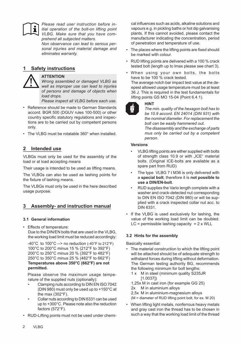
Please read user instruction before in-itial operation of the bolt-on lifting point VLBG. Make sure that you have com-prehend all subjected matters. Non observance can lead to serious per-sonal injuries and material damage and eliminates warranty.
1 Safety instructionsATTENTION Wrong assembled or damaged VLBG as well as improper use can lead to injuries of persons and damage of objects when load drops.Please inspect all VLBG before each use.
• Reference should be made to German Standards accord. BGR 500 (DGUV rules 100-500) or other country specific statutory regulations and inspec-tions are to be carried out by competent persons only.
• The VLBG must be rotatable 360° when installed.
2 Intended use VLBGs must only be used for the assembly of the load or at load accepting meansTheir usage is intended to be used as lifting means.The VLBGs can also be used as lashing points for the fixture of lashing means.The VLBGs must only be used in the here described usage purpose.
3 Assembly- and instruction manual
3.1 General information
• Effects of temperature: Due to the DIN/EN bolts that are used in the VLBG, the working load limit must be reduced accordingly:
-40°C to 100°C --> no reduction (-40°F to 212°F) 100°C to 200°C minus 15 % (212°F to 392°F) 200°C to 250°C minus 20 % (392°F to 482°F) 250°C to 350°C minus 25 % (482°F to 662°F) Temperatures above 350°C (662°F) are not permitted.
Please observe the maximum usage tempe-rature of the supplied nuts (optionally): • Clamping nuts according to DIN EN ISO 7042 (DIN 980) must only be used up to +150°C at the max (302°F). • Collar nuts according to DIN 6331 can be used up to +300°C. Please note also the reduction factors (572°F).
• RUD-Lifting points must not be used under chemi-
cal influences such as acids, alkaline solutions and vapours e.g. in pickling baths or hot dip galvanising plants. If this cannot avoided, please contact the manufacturer indicating the concentration, period of penetration and temperature of use.
• The places where the lifting points are fixed should be marked with colour.
• RUD lifting points are delivered with a 100 % crack tested bolt (length up to lmax please see chart 3).
• When us ing your own bo l ts , the bo l ts have to be 100 % crack tested. The average notch bar impact test value at the de-epest allowed usage temperature must be at least 36 J. This is required in the test fundamentals for lifting points GS MO 15-04 (Point 6.4.1).
HINTThe min. quality of the hexagon bolt has to be 10.9 accord. EN 24014 (DIN 931) with the nominal diameter. For replacement the bolt can be easily hammered out. The disassembly and the exchange of parts mus only be carried out by a competent person.
Versions • VLBG lifting points are either supplied with bolts
of strength class 10.9 or with „ICE“ material bolts. (Original ICE-bolts are available as a spare part from RUD)
• The type VLBG 7 t M36 is only delivered with a special bolt, therefore it is not possible to use a DIN/EN-bolt.
• RUD supplies the Vario length complete with a washer and crack-detected nut corresponding to DIN EN ISO 7042 (DIN 980) or will be sup-plied with a crack inspected collar nut acc. to DIN 6331.
• If the VLBG is used exclusively for lashing, the value of the working load limit can be doubled. LC = permissible lashing capacity = 2 x WLL
3.2 Hints for the assembly
Basically essential:• The material construction to which the lifting point
will be attached should be of adequate strength to withstand forces during lifting without deformation. The German testing authority BG, recommends the following minimum for bolt lengths: 1 x M in steel (minimum quality S235JR [1.0037]) 1,25x M in cast iron (for example GG 25) 2x M in aluminium alloys 2,5x M in aluminium-magnesium alloys (M = diameter of RUD lifting point bolt, for ex. M 20)
• When lifting light metals, nonferrous heavy metals and gray cast iron the thread has to be chosen in such a way that the working load limit of the thread
3VLBG
corresponds to the requirements of the respective base material.
• The lifting points must be positioned on the load in such a way that movement is avoided during lifting:
• For single leg lifts, the load ring should be positioned vertically above the centre of gravity of the load. • For two leg lifts, the lifting points must be equidistant to/or above the centre of gravity of the load. • For three and four leg lifts, the lifting points should be arranged symmetrically around the centre of gravity in the same plane, if possible.
• Load symmetry: The working load limit of individual RUD lifting points are calculated using the following formula and are based on symmetrical loading:
The calculation of load bearing legs is as follows:
table 1: Load bearing strands (see table 2) HINTWith unsymmetrical loads, the WLL of each Lifting Point must be at least as high as the weight of the load.
• A plane bolt-on surface (ØD, table 3) with a per-pendicular thread hole must be guaranteed. The thread must be carried out acc. to DIN 76 (coun-tersink max. 1.05xd)
• The holes must be drilled with a sufficient depth in order to guarantee compatibility with the supporting surface.
• The VLBG must be rotatable 360° when installed. Please observe the following:
• For a single use hand tightening with a span-ner is sufficiant. Bolt supporting area must sit proper on bolt-on surface.
• For long term application the VLBG must be tightened with torque according to table 3 (+/- 10 %).
WLL = working load limitG = load weight (kg)n = number of load bearing legsß = angle of inclination of the chain to the vertical
WLL=G
n x cos ß
• When turning loads using the VLBG (see chapter 3.3.2 permissible lifting- and turning process) it is necessary to tighten the bolt with a torque (+/- 10 %) acc. to chart 3.
• With shock loading or vibrations, especially at through hole fixtures with a nut at the end of the bolt, accidential release can occure. Securing possibilities: Observe torque moment, use liquid securing glue f.e. Loctite (can be adap-ted to the usage, observe manufacturer hints) or assemble a form closure bolt locking device f.e. a castle nut with cotter pin, locknut etc.
• Finally check the proper assembly (see chapter 4 Inspection criteria).
3.3 User instructions
3.3.1 General information for the usage
• Before every usage, control in regularly periods the whole lifting point in regard of the continuous aptitude as a lifting mean, whether it is tightened (torqued), or has strong corrosion, wear, deforma-tions etc. (see chapter 4 Inspection criteria).
ATTENTION Wrong assembled or damaged VLBG as well as improper use can lead to injuries of persons and damage of objects when load drops.Please inspect all VLBG before each use.
• Adjust to the direction of pull, before attaching to the lifting means. The load ring should be free movable and must not touch edges.
• All fittings connected to the VLBG should be free moving. When connecting and disconnecting the lifting means (sling chain) pinches and impacts should be avoided.
• Damage of the lifting means caused by sharp edges should be avoided as well.
symmetrical asymmetricaltwo leg 2 1three / four leg 3 1

4 VLBG
F
3.3.2 Allowed lifting and turning operations
Pic. 1: Possible turning operation with the VLBG
The following turning operations are allowed• Turning operations where the load ring will be
turned into the load directionWARNING The load ring must not support itself at edges or other attachments.Also the attached lifting mean must not touch the head oft he bolt.
Pic. 2: Pivoting in load direction
• Turning operations where the VLBG will be turned around the bolt axle (exception: see chapter 3.3.3 Forbidden lifting and turning operations). After a full turn by 180° the torque of the bolt must be checked.
WARNING Observe the requested torque value before each lifting or turning operation.
3.3.3 Forbidden lifting and turning operations
The following operations are forbidden:WARNINGThe turning of the VLBG under load in the direction of the bolt axle (+15°) is forbidden.
Pic. 3: Forbidden turning direction at loading in the direction of the axle.
F 15°
5VLBG
3.4 Hints for periodical inspections
Have VLBG checked by a competent person in peri-ods which are determined by the usage, but at least 1x per year, in regard of the ongoing appropriateness of the lifting point (see chapter 4 Inspection criteria).Depending on the usage conditions, f.e. frequent usage, increased wear or corrosion, it might be ne-cessary to check in shorter periods than one year. The inspection has also to be carried out after accidents and special incidents.
RUD components are designed for a dynamical loading of 20 000 load cycles at nominal working load. The BG/DGUV recommends: At a high dynamic loading with high numbers of load cycles (continious work) the bearing stress acc. to FEM group 1Bm (M3 acc. to DIN 818-7) must be reduced.
4 Inspection criteriaObserve and control the following points before each operation, in regularly periods, after the assembly and special incidents.• Ensure correct bolt and nut size, quality and length.• Ensure compatibility of bolt thread and tapped hole
--> control of the torque• The lifting point should be complete. • The working load limit and manufacturers stamp
should be clearly visible.• Deformation of the component parts such as body,
load ring and bolt.• Mechanical damage, such as notches, particularly
in high stress areas. • Wear should be not more than 10 % of cross sec-
tional diameter. • Evidence of corrosion. • Evidence of cracks.• Damage at the bolt, nut and/or thread. • The body of the VLBG must be free to rotate.
6 VLBG
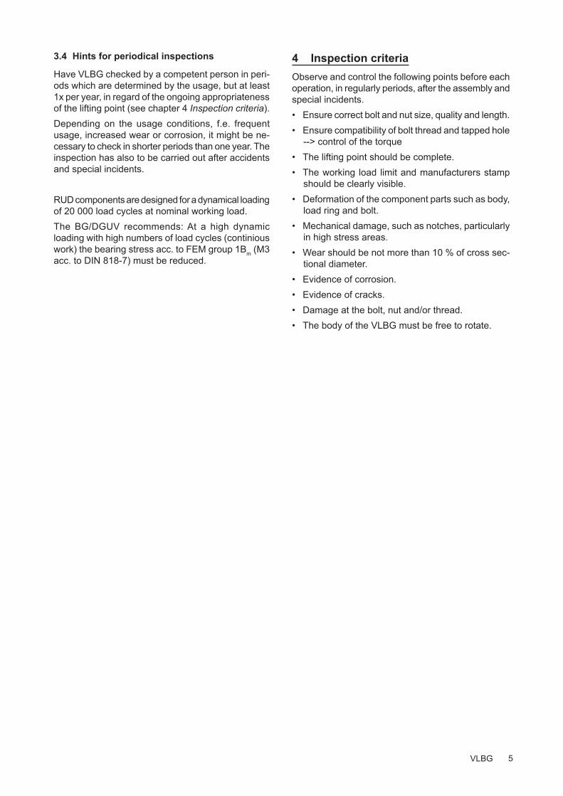
table 2: WLL in tons (above / top) and in lbs (below / bottom)
Method of lift
Number of legs 1 1 2 2 2 2 2 3 & 4 3 & 4 3 & 4 Angle of inclination <ß 0° 90° 0° 90° 0-45° 45-60° unsymm. 0-45° 45-60° unsymm. Factor 1 1 2 2 1.4 1 1 2.1 1.5 1
Type Thread WLL in metric tons, bolted and adjusted in the direction of pull
VLBG 0.3 t M 8 0.3 0.3 0.6 0.6 0.42 0.3 0.3 0.63 0.45 0.3 VLBG 0.63 t M 10 / 3/8“ 0.63 0.63 1.26 1.26 0.88 0.63 0.63 1.32 0.95 0.63VLBG 1 t M 12 / 1/2“ 1 1 2 2 1.4 1 1 2.1 1.5 1VLBG 1.2 t M 14 1.2 1.2 2.4 2.4 1.68 1.2 1.2 2.52 1.8 1.2VLBG 1.5 t M 16 / 5/8“ 1.5 1.5 3 3 2.1 1.5 1.5 3.15 2.25 1.5VLBG 2 t M 18 2 2 4 4 2.8 2 2 4.2 3 2VLBG 2.5 t M 20 / 3/4“ / 7/8“ 2.5 2.5 5 5 3.5 2.5 2.5 5.25 3.75 2.5 VLBG 2.5 t M22 2.5 2.5 5 5 3.5 2.5 2.5 5.25 3.75 2.5 VLBG 4 t M 24 / M27 / 1“ 4 4 8 8 5.6 4 4 8.4 6 4VLBG 5 t M 30 / 1 1/4“ 5 5 10 10 7 5 5 10.5 7.5 5VLBG 7 t M 36 7 7 14 14 9.8 7 7 14.7 10.5 7VLBG 8 t M 36 / 1 1/2“ 8 8 16 16 11.2 8 8 16.8 12 8VLBG 10 t M 42 10 10 20 20 14 10 10 21 15 10VLBG 15 t M 42 15 15 30 30 21 15 15 31.5 22.5 15VLBG 20 t M 48 / 2“ 20 20 40 40 28 20 20 42 30 20
Type Thread WLL in lbs, bolted and adjusted in the direction of pull
VLBG 0.3 t M 8 660 660 1320 1320 925 660 660 1400 990 660
VLBG 0.63 t M 10 / 3/8“ 1400 1400 2800 2800 1940 1400 1400 2910 2080 1400
VLBG 1 t M 12 / 1/2“ 2200 2200 4400 4400 3080 2200 2200 4620 3300 2200
VLBG 1.2 t M 14 2640 2640 5280 5280 3700 2640 2640 5545 3960 2640
VLBG 1.5 t M 16 / 5/8“ 3300 3300 6600 6600 4620 3300 3300 6930 4950 3300
VLBG 2 t M 18 4400 4400 8800 8800 6160 4400 4400 9250 6600 4400
VLBG 2.5 t M 20 / 3/4“ / 7/8“ 5500 5500 11000 11000 7700 5500 5500 11550 8250 5500
VLBG 2.5 t M22 5500 5500 11000 11000 7700 5500 5500 11550 8250 5500
VLBG 4 t M 24 / M 27 / 1“ 8800 8800 17600 17600 12320 8800 8800 18480 13200 8800
VLBG 5 t M 30 / 1 1/4“ 11000 11000 22000 22000 15400 11000 11000 23100 16500 11000
VLBG 7 t M 36 15400 15400 30800 30800 21500 15400 15400 32350 23100 15400
VLBG 8 t M 36 / 1 1/2“ 17600 17600 35200 35200 24640 17600 17600 36960 26400 17600
VLBG 10 t M 42 22000 22000 44000 44000 30800 22000 22000 46200 33000 22000
VLBG 15 t M 42 33000 33000 66000 66000 46200 33000 33000 69300 49500 33000
VLBG 20 t M 48 / 2“ 44000 44000 88000 88000 61600 44000 44000 92400 66000 44000
Forbidden! (Overhead loading)
F
Pic. 4: Overhead loading
7VLBG
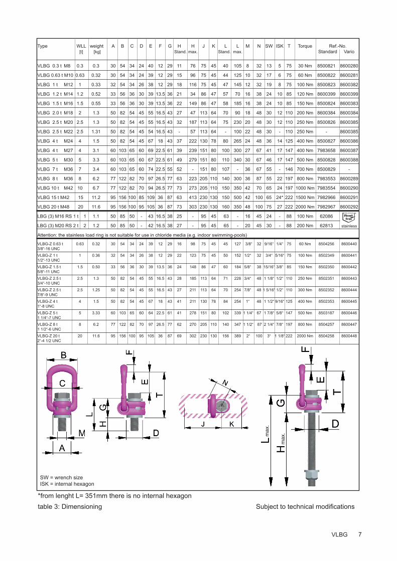
*from lenght L= 351mm there is no internal hexagon table 3: Dimensioning Subject to technical modifi cations
Type WLL weight A B C D E F G H H J K L L M N SW ISK T Torque Ref.-No. [t] [kg] Stand. max. S tand. max. Standard Vario
VLBG 0.3 t M8 0.3 0.3 30 54 34 24 40 12 29 11 76 75 45 40 105 8 32 13 5 75 30 Nm 8500821 8600280
VLBG 0.63 t M10 0.63 0.32 30 54 34 24 39 12 29 15 96 75 45 44 125 10 32 17 6 75 60 Nm 8500822 8600281
VLBG 1 t M12 1 0.33 32 54 34 26 38 12 29 18 116 75 45 47 145 12 32 19 8 75 100 Nm 8500823 8600382
VLBG 1.2 t M14 1.2 0.52 33 56 36 30 39 13.5 36 21 34 86 47 57 70 16 38 24 10 85 120 Nm 8600399 8600399
VLBG 1.5 t M16 1.5 0.55 33 56 36 30 39 13.5 36 22 149 86 47 58 185 16 38 24 10 85 150 Nm 8500824 8600383
VLBG 2.0 t M18 2 1.3 50 82 54 45 55 16.5 43 27 47 113 64 70 90 18 48 30 12 110 200 Nm 8600384 8600384
VLBG 2.5 t M20 2.5 1.3 50 82 54 45 55 16.5 43 32 187 113 64 75 230 20 48 30 12 110 250 Nm 8500826 8600385
VLBG 2.5 t M22 2.5 1.31 50 82 54 45 54 16.5 43 - 57 113 64 - 100 22 48 30 - 110 250 Nm - 8600385
VLBG 4 t M24 4 1.5 50 82 54 45 67 18 43 37 222 130 78 80 265 24 48 36 14 125 400 Nm 8500827 8600386
VLBG 4 t M27 4 3.1 60 103 65 60 69 22.5 61 39 239 151 80 100 300 27 67 41 17 147 400 Nm 7983658 8600387
VLBG 5 t M30 5 3.3 60 103 65 60 67 22.5 61 49 279 151 80 110 340 30 67 46 17 147 500 Nm 8500828 8600388
VLBG 7 t M36 7 3.4 60 103 65 60 74 22.5 55 52 - 151 80 107 - 36 67 55 - 146 700 Nm 8500829 -
VLBG 8 t M36 8 6.2 77 122 82 70 97 26.5 77 63 223 205 110 140 300 36 87 55 22 197 800 Nm 7983553 8600289
VLBG 10 t M42 10 6.7 77 122 82 70 94 26.5 77 73 273 205 110 150 350 42 70 65 24 197 1000 Nm 7983554 8600290
VLBG 15 t M42 15 11.2 95 156 100 85 109 36 87 63 413 230 130 150 500 42 100 65 24* 222 1500 Nm 7982966 8600291
VLBG 20 t M48 20 11.6 95 156 100 95 105 36 87 73 303 230 130 160 350 48 100 75 27 222 2000 Nm 7982967 8600292
LBG (3) M16 RS 1 t 1 1.1 50 85 50 - 43 16.5 38 25 - 95 45 63 - 16 45 24 - 88 100 Nm 62086
LBG (3) M20 RS 2 t 2 1.2 50 85 50 - 42 16.5 38 27 - 95 45 65 - 20 45 30 - 88 200 Nm 62813
Attention: the stainless load ring is not suitable for use in chloride media (e.g. indoor swimming-pools)
VLBG-Z 0.63 t 0.63 0.32 30 54 34 24 39 12 29 16 98 75 45 45 127 3/8“ 32 9/16“ 1/4“ 75 60 Nm 8504256 86004403/8“-16 UNC
VLBG-Z 1 t 1 0.36 32 54 34 26 38 12 29 22 123 75 45 50 152 1/2“ 32 3/4“ 5/16“ 75 100 Nm 8502349 86004411/2“-13 UNC
VLBG-Z 1.5 t 1.5 0.50 33 56 36 30 39 13.5 36 24 148 86 47 60 184 5/8“ 38 15/16“ 3/8“ 85 150 Nm 8502350 86004425/8“-11 UNC
VLBG-Z 2.5 t 2.5 1.3 50 82 54 45 55 16.5 43 28 185 113 64 71 228 3/4“ 48 1 1/8“ 1/2“ 110 250 Nm 8502351 86004433/4“-10 UNC
VLBG-Z 2.5 t 2.5 1.25 50 82 54 45 55 16.5 43 27 211 113 64 70 254 7/8“ 48 1 5/16“ 1/2“ 110 300 Nm 8502352 86004447/8“-9 UNC
VLBG-Z 4 t 4 1.5 50 82 54 45 67 18 43 41 211 130 78 84 254 1“ 48 1 1/2“ 9/16“ 125 400 Nm 8502353 86004451“-8 UNC
VLBG-Z 5 t 5 3.33 60 103 65 60 64 22.5 61 41 278 151 80 102 339 1 1/4“ 67 1 7/8“ 5/8“ 147 500 Nm 8503187 86004461 1/4“-7 UNC
VLBG-Z 8 t 8 6.2 77 122 82 70 97 26.5 77 62 270 205 110 140 347 1 1/2“ 87 2 1/4“ 7/8“ 197 800 Nm 8504257 86004471 1/2“-6 UNC
VLBG-Z 20 t 20 11.6 95 156 100 95 105 36 87 69 302 230 130 156 389 2“ 100 3“ 1 1/8“ 222 2000 Nm 8504258 86004482“-4 1/2 UNC
SW = wrench sizeISK = internal hexagon
max
.
max
.
stainless


![Load Ring for bolting >VLBG< - RUD Ketten...1 x M in steel (minimum quality S235JR [1.0037]) 1,25 x M in cast iron (for example GG 25) 2 x M in aluminium alloys 2,5 x M in aluminium-magnesium](https://img.dokumen.tips/doc/110x75/5ed2274062fb5e456c076016/load-ring-for-bolting-vlbg-rud-ketten-1-x-m-in-steel-minimum-quality.jpg)