Embed Size (px)
Citation preview
Load Balancing Microsoft Remote Desktop Services
Deployment Guidev1.2.4
Copyright © Loadbalancer.org

Table of Contents
1. About this Guide.........................................................................................................................................4
2. Loadbalancer.org Appliances Supported..........................................................................................4
3. Loadbalancer.org Software Versions Supported............................................................................4
4. Microsoft Windows Versions Supported...........................................................................................4
5. Remote Desktop Services........................................................................................................................5Introduction............................................................................................................................................................................. 5
Role Services............................................................................................................................................................................ 5
Windows 2008 R2 RDS Deployment Overview...........................................................................................................6
Windows 2012 RDS Deployment Overview.................................................................................................................. 6
6. Load Balancing Remote Desktop Services.......................................................................................9Basic Concepts........................................................................................................................................................................ 9
Load Balanced Ports & Services......................................................................................................................................... 9
Persistence (Server Affinity) Requirements & Options...............................................................................................9
Connection Broker Persistence................................................................................................................................... 10
Client Source IP Address Persistence........................................................................................................................ 10
RDP Cookie Persistence................................................................................................................................................. 10
Load Balancer Deployment Mode.................................................................................................................................. 11
7. Remote Desktop Services – Load Balancing Scenarios.............................................................12Scenario 1 - Load Balancing Stand alone Session Hosts.........................................................................................12
Scenario 2 - Load Balancing Connection Brokers with Session Hosts...............................................................13
Scenario 3 - Load Balancing Connection Brokers with Virtualization Hosts....................................................14
Scenario 4 - Load Balancing Session Hosts when Deployed with Connection Broker................................15
Scenario 5 - Load Balancing Gateways......................................................................................................................... 16
Scenario 6 - Load Balancing Web Access Servers..................................................................................................... 17
8. Loadbalancer.org Appliance – the Basics.......................................................................................18Virtual Appliance Download & Deployment............................................................................................................... 18
Initial Network Configuration.......................................................................................................................................... 18
Accessing the Web User Interface (WebUI)................................................................................................................. 19
HA Clustered Pair Configuration.................................................................................................................................... 20
9. Load Balancing Session Hosts Deployed without Connection Broker (Scenario 1)........21RDS Installation & Configuration..................................................................................................................................... 21
Appliance Configuration.................................................................................................................................................... 21
Setting up the Virtual Service (VIP).............................................................................................................................. 21
Setting up the Real Servers (RIPs)................................................................................................................................ 22
Applying the new Layer 7 Settings.............................................................................................................................. 22
Testing & Verification.......................................................................................................................................................... 22
10. Load Balancing Connection Brokers (Scenario's 2 & 3)...........................................................23RDS Installation & Configuration.................................................................................................................................... 23
Appliance Configuration.................................................................................................................................................... 23
Setting up the Virtual Service (VIP)............................................................................................................................. 23
Setting up the Real Servers (RIPs)............................................................................................................................... 24
Applying the new Layer 7 Settings.............................................................................................................................. 24
Testing & Verification.......................................................................................................................................................... 25
Microsoft RDS Deployment Guide v1.2.4
11. Load Balancing Session Hosts when Deployed with Connection Broker (Scenario 4) 25RDS Installation & Configuration.................................................................................................................................... 25
Appliance Configuration................................................................................................................................................... 26
Setting up the Virtual Service (VIP)............................................................................................................................. 26
Setting up the Real Servers (RIPs)............................................................................................................................... 26
Applying the new Layer 7 Settings.............................................................................................................................. 27
Testing & Verification.......................................................................................................................................................... 27
12. Load Balancing Gateways (Scenario 5)..........................................................................................27RDS Installation & Configuration.................................................................................................................................... 27
Appliance Configuration................................................................................................................................................... 29
Setting up the HTTPS Virtual Service (VIP)............................................................................................................... 29
Setting up the Real Servers (RIPs)............................................................................................................................... 30
Applying the new Layer 7 Settings.............................................................................................................................. 31
Setting up the UDP Virtual Service (VIP).................................................................................................................... 31
Setting up the UDP Real Servers (RIPs)...................................................................................................................... 31
Setting up the Connection Broker Virtual Service (VIP).......................................................................................32
Testing & Verification.......................................................................................................................................................... 32
13. Load Balancing Web Access Servers (Scenario 6)......................................................................32RDS Installation & Configuration.................................................................................................................................... 32
Appliance Configuration.................................................................................................................................................... 32
Setting up the Virtual Service (VIP)............................................................................................................................. 32
Setting up the Real Servers (RIPs)................................................................................................................................ 33
Applying the new Layer 7 Settings.............................................................................................................................. 34
Testing & Verification......................................................................................................................................................... 34
14. Technical Support.................................................................................................................................34
15. Further Documentation.......................................................................................................................34
16. Conclusion...............................................................................................................................................34
17. Appendix....................................................................................................................................................351 - Load Balancer Deployment Methods...................................................................................................................... 35
Layer 4 DR Mode.............................................................................................................................................................. 35
Layer 4 NAT Mode........................................................................................................................................................... 36
Layer 4 SNAT Mode......................................................................................................................................................... 37
Layer 7 SNAT Mode......................................................................................................................................................... 38
2 - Solving the ARP Problem............................................................................................................................................ 39
3 - Server Feedback Agent................................................................................................................................................ 43
4 - Configuring Windows 2008 R2 for Routing Token Redirection Mode.......................................................45
5 - Clustered Pair Configuration – Adding a Slave Unit..........................................................................................46
6 - Company Contact Information................................................................................................................................ 49
Microsoft RDS Deployment Guide v1.2.4

About this Guide
1. About this GuideThis guide details the steps required to configure a load balanced Microsoft Remote Desktop Services (RDS) environment utilizing Loadbalancer.org appliances. It covers the configuration of the load balancers and also any Microsoft Remote Desktop Services configuration changes that are required to enable load balancing. The guide focuses on Windows 2012 and later, although reference is made to 2008 R2 where appropriate.
For more information about initial appliance deployment, network configuration and using the Web User Interface (WebUI), please also refer to the relevant Administration Manual:
• v7 Administration Manual
• v8 Administration Manual
2. Loadbalancer.org Appliances SupportedAll our products can be used with Remote Desktop Services. The complete list of models is shown below:
Discontinued Models Current Models *
Enterprise R16 Enterprise R20
Enterprise VA R16 Enterprise MAX
Enterprise VA Enterprise 10G
Enterprise R320 Enterprise Ultra
Enterprise VA R20
Enterprise VA MAX
Enterprise AWS **
Enterprise AZURE **
* For full specifications of these models please refer to: http://www.loadbalancer.org/products/hardware
** Some features may not be supported, please check with Loadbalancer.org support
3. Loadbalancer.org Software Versions Supported
• V7.6.4 and later
4. Microsoft Windows Versions Supported
• Windows 2008 R2 and later
Microsoft RDS Deployment Guide v1.2.4
Page 4
Remote Desktop Services
5. Remote Desktop Services
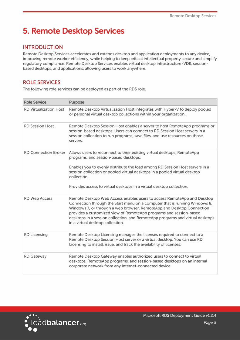
INTRODUCTIONRemote Desktop Services accelerates and extends desktop and application deployments to any device, improving remote worker efficiency, while helping to keep critical intellectual property secure and simplifyregulatory compliance. Remote Desktop Services enables virtual desktop infrastructure (VDI), session-based desktops, and applications, allowing users to work anywhere.
ROLE SERVICESThe following role services can be deployed as part of the RDS role.
Role Service Purpose
RD Virtualization Host Remote Desktop Virtualization Host integrates with Hyper-V to deploy pooled or personal virtual desktop collections within your organization.
RD Session Host Remote Desktop Session Host enables a server to host RemoteApp programs or session-based desktops. Users can connect to RD Session Host servers in a session collection to run programs, save files, and use resources on those servers.
RD Connection Broker Allows users to reconnect to their existing virtual desktops, RemoteApp programs, and session-based desktops.
Enables you to evenly distribute the load among RD Session Host servers in a session collection or pooled virtual desktops in a pooled virtual desktop collection.
Provides access to virtual desktops in a virtual desktop collection.
RD Web Access Remote Desktop Web Access enables users to access RemoteApp and Desktop Connection through the Start menu on a computer that is running Windows 8, Windows 7, or through a web browser. RemoteApp and Desktop Connection provides a customized view of RemoteApp programs and session-based desktops in a session collection, and RemoteApp programs and virtual desktops in a virtual desktop collection.
RD Licensing Remote Desktop Licensing manages the licenses required to connect to a Remote Desktop Session Host server or a virtual desktop. You can use RD Licensing to install, issue, and track the availability of licenses.
RD Gateway Remote Desktop Gateway enables authorized users to connect to virtual desktops, RemoteApp programs, and session-based desktops on an internal corporate network from any Internet-connected device.
Microsoft RDS Deployment Guide v1.2.4
Page 5

Remote Desktop Services
WINDOWS 2008 R2 RDS DEPLOYMENT OVERVIEWInstallation of RDS under Windows 2008 R2 uses the traditional role/service concept. The RDS infrastructure must be built by manually installing the required services on the various servers to build the desired infrastructure.
The screenshot below shows the initial service selection screen for installing RDS under Windows 2008 R2.
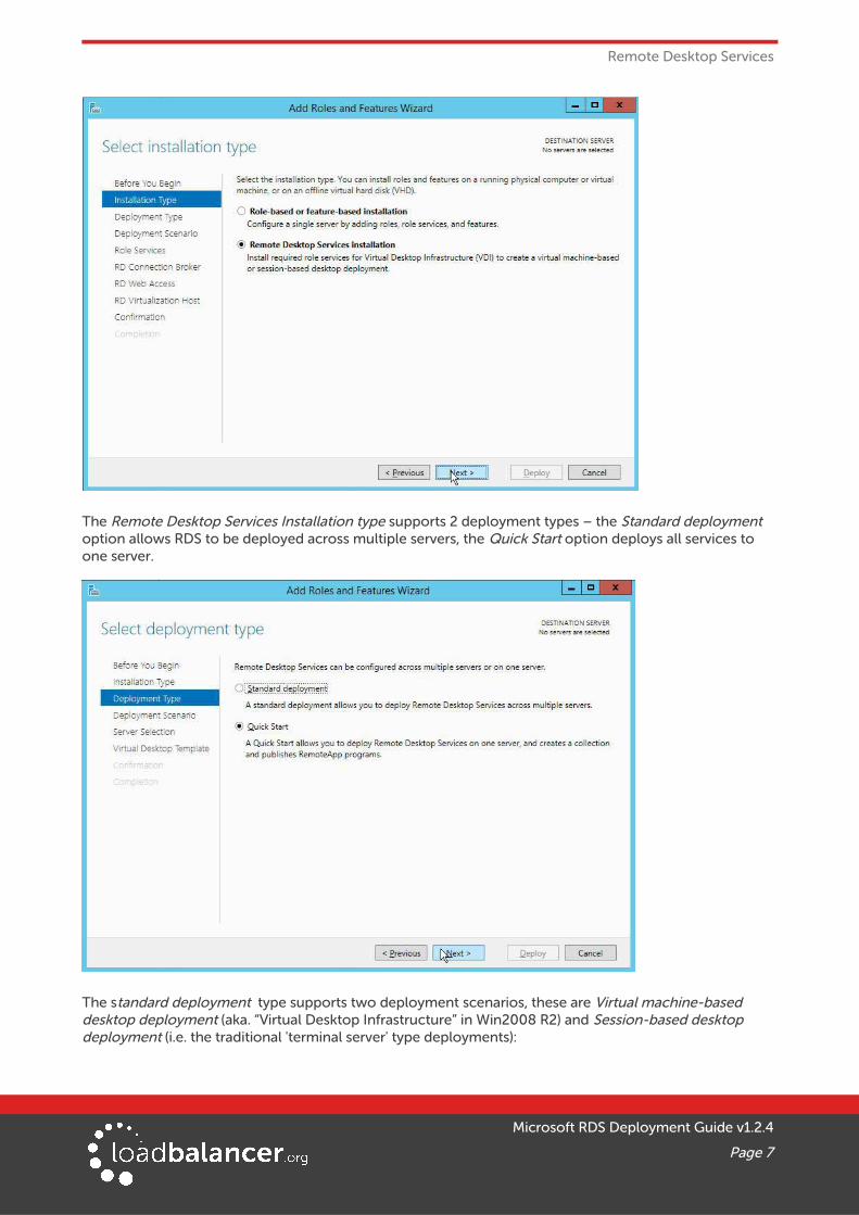
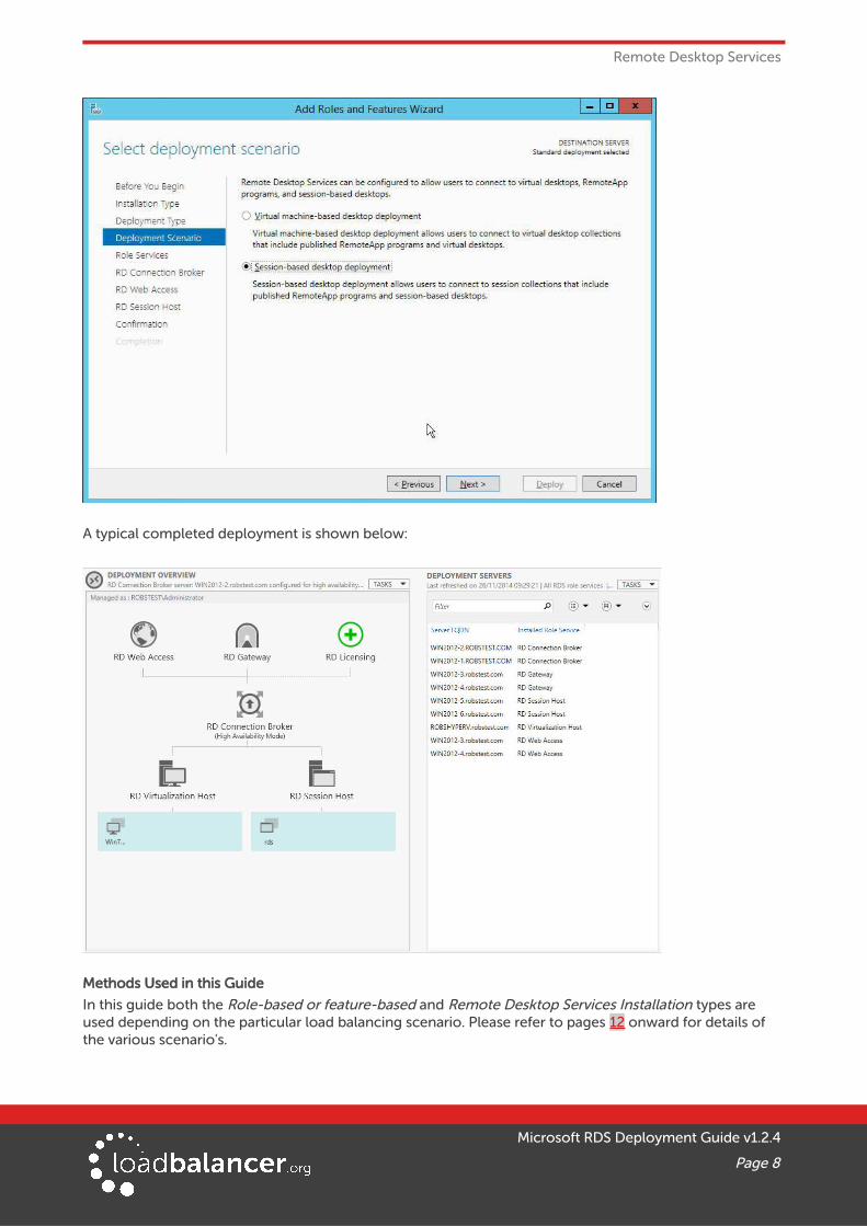
WINDOWS 2012 RDS DEPLOYMENT OVERVIEWWindows 2012 provides two installation types, the first is the Role-based or feature-based installation where roles and services are installed on individual servers as per Windows 2008 R2 and secondly RemoteDesktop Services Installation which is a centrally based installation which enables all role services to be installed on multiple servers from one place which is a substantial improvement on 2008 R2.
Microsoft RDS Deployment Guide v1.2.4
Page 6
Remote Desktop Services
The Remote Desktop Services Installation type supports 2 deployment types – the Standard deployment option allows RDS to be deployed across multiple servers, the Quick Start option deploys all services to one server.
The standard deployment type supports two deployment scenarios, these are Virtual machine-based desktop deployment (aka. “Virtual Desktop Infrastructure” in Win2008 R2) and Session-based desktop deployment (i.e. the traditional 'terminal server' type deployments):
Microsoft RDS Deployment Guide v1.2.4
Page 7
Remote Desktop Services
A typical completed deployment is shown below:
Methods Used in this Guide
In this guide both the Role-based or feature-based and Remote Desktop Services Installation types are used depending on the particular load balancing scenario. Please refer to pages 12 onward for details of the various scenario's.
Microsoft RDS Deployment Guide v1.2.4
Page 8

Load Balancing Remote Desktop Services
6. Load Balancing Remote Desktop Services
Note:
It's highly recommended that you have a working RDS environment first before implementing the load balancer.
BASIC CONCEPTSThe load balancer is deployed in front of the various RDS servers to provide load balancing and failover functionality. Clients then connect to a Virtual Service (VIP) on the load balancer rather than connecting directly to a one of the RDS servers. These connections are then load balanced between the associated RDS servers to distribute the load according to the load balancing algorithm selected.
Using a Loadbalancer.org clustered pair with multiple Microsoft RDS servers enables the following key benefits:
• High-Availability – Servers are continually health checked by the load balancer and are automatically removed from the load balanced pool if the health check fails
• Performance – Adding additional servers distributes the load and improves performance
• Maintainability – Servers can easily be removed from the pool in a controlled manner to allow maintenance tasks such as applying software updates to be carried out
LOAD BALANCED PORTS & SERVICESThe following table shows the RDS ports and service that are load balanced:
Protocol Port Purpose/Service
TCP/HTTPS 443 HTTPS (RD Gateway, RD Web Access)
TCP/UDP/RDP 3389 RDP (UDP support was added in RDP v8.0)
UDP 3391 RDP (RD Gateway)
PERSISTENCE (SERVER AFFINITY) REQUIREMENTS & OPTIONSPersistence means consistently sending a particular client to the same back-end server during a particular session. This is critical for some role services and not relevant to others. The following table summarizes the requirements:
Service Persistence Required?
Comments Load Balancer Persistence Methods
Virtualization Hosts Yes Required to enable users to reconnect to their desktops
Connection Broker
Session Hosts Yes Required to enable users to reconnect to their session
Connection Broker, client source IPaddress or RDP cookie (the specificmethod supported depends on deployment architecture)
Connection Brokers No Data is stored in an SQL DB, brokers only relay the request
Persistence is not required since the load balancer only handles the
Microsoft RDS Deployment Guide v1.2.4
Page 9

Load Balancing Remote Desktop Services
initial connection and not the active RDP session
Gateways Yes Both SSL connections must goto the same Gateway server
Client source IP address
Web Access Servers Yes Uses IIS with authentication which is to a specific server
Client source IP address
CONNECTION BROKER PERSISTENCERemote Desktop Connection Broker provides the following functionality:
• Allows users to reconnect to their existing virtual desktops, RemoteApp programs, and session-based desktops
• Enables you to evenly distribute the load among RD Session Host servers in a session collection or pooled virtual desktops in a pooled virtual desktop collection
• Provides access to virtual desktops in a virtual desktop collection
All user sessions are stored as records in a central SQL database. The database is updated and queried by the RDS servers whenever users log on, log off, or disconnect their sessions.
The load balancer is able to interact with Connection Broker by enabling Routing Token Redirection Modeon the RDS servers. This mode allows the reconnection of disconnected sessions by utilizing a routing token to enable the load balancer to re–connect the client to the correct Session Host.
Note:
For more information on how this works please refer to the following Microsoft URLs:
a) Redirection Modes
b) Session Directory and Load Balancing Using Terminal Server
Note that b) was written for Win2003, but the redirection concepts on p25 to p27 also apply to later versions of Windows.
CLIENT SOURCE IP ADDRESS PERSISTENCEThis method is appropriate when each clients actual source IP addresses can be seen by the load balancer.This will typically be the case within a LAN but in some situations – e.g. a remote office connecting via some kind of NAT device, all clients would appear to come from the same address and therefore load may not be evenly distributed between the RDS servers.
RDP COOKIE PERSISTENCEThis method utilizes the cookie sent from the client in the Connection Request PDU. This cookie is createdwhen the username is entered at the first client login prompt (mstsc.exe). If the username is not entered here, the cookie is not created.
The cookie only supports up to 9 characters, so this method may have limited use, especially in cases where users login using the domain\username format. In this case, if the domain name was 9 characters inlength, the RDP cookie would be the same for all users, resulting in all sessions being sent to the same session host. If users login using the UPN format (User Principle Name), i.e. username@domain, it's more likely to be unique.
Microsoft RDS Deployment Guide v1.2.4
Page 10

Load Balancing Remote Desktop Services
Note:
When RDP cookie persistence is selected, the load balancer will attempt to use RDP cookie persistence, but if a cookie is not found, source IP persistence will be used instead as a fallback.
Note:
In certain scenarios depending on client version as well as the specific client & server settings, the RDP cookie (mstshash) is not consistently sent. Please also refer to our blog post on this topic: http://www.loadbalancer.org/blog/microsoft-drops-support-for-mstshash-cookies
Update (October 2015) – with the latest versions of Windows Servers & RDP Client, this problemappears to have been resolved.
LOAD BALANCER DEPLOYMENT MODEThe load balancer can be deployed in 4 fundamental ways: Layer 4 DR mode, Layer 4 NAT mode, Layer 4 SNAT mode and Layer 7 SNAT mode. These modes are explained in detail in the appendix starting on page35.
For simplicity, Layer 7 SNAT mode is recommended for most RDS load balancing scenarios (see the section starting on page 12 for more details) and is used for most of the configurations presented in this guide. Note that In all cases except scenario 4 where the load balancer must interact with the routing token, the other modes can also be used.
When load balancing the UDP part of RD Gateway, layer 7 SNAT mode cannot be used as it only supports TCP. Instead, a layer 4 DR mode VIP is used in this guide (see page 31) although layer 4 NAT & SNAT modes can also be used.
Microsoft RDS Deployment Guide v1.2.4
Page 11
Remote Desktop Services – Load Balancing Scenarios
7. Remote Desktop Services – Load Balancing Scenarios
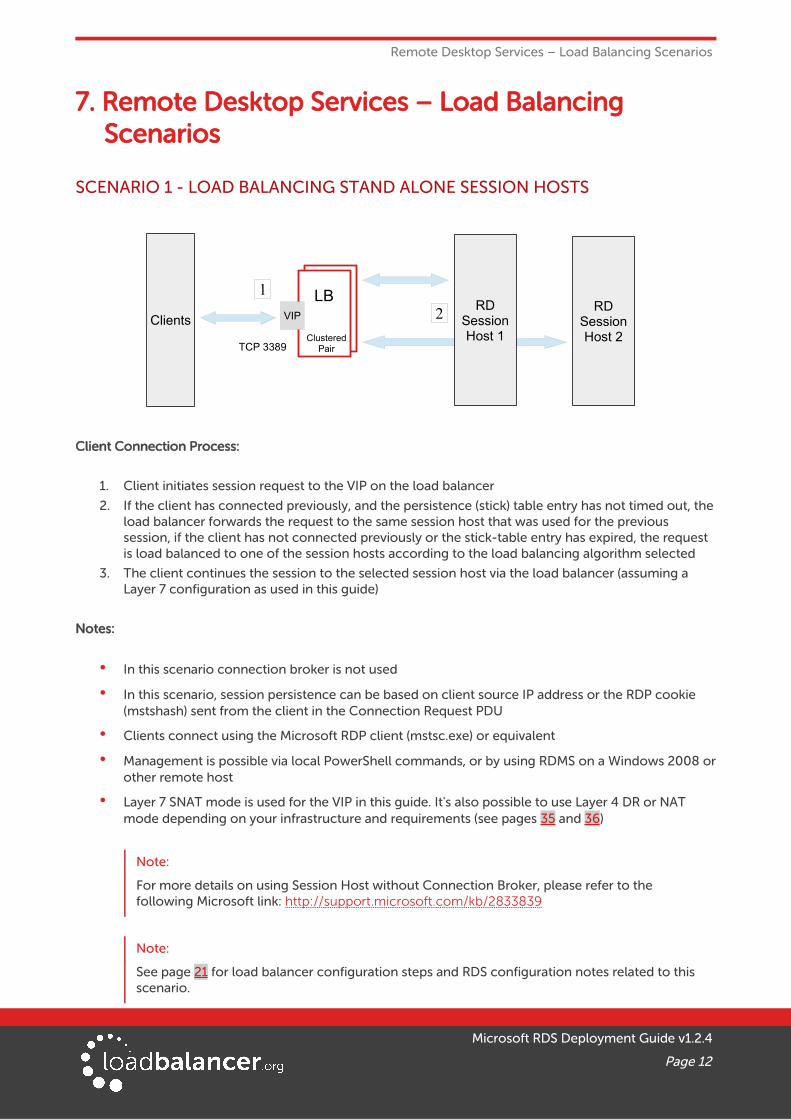
SCENARIO 1 - LOAD BALANCING STAND ALONE SESSION HOSTS
Client Connection Process:
1. Client initiates session request to the VIP on the load balancer
2. If the client has connected previously, and the persistence (stick) table entry has not timed out, theload balancer forwards the request to the same session host that was used for the previous session, if the client has not connected previously or the stick-table entry has expired, the request is load balanced to one of the session hosts according to the load balancing algorithm selected
3. The client continues the session to the selected session host via the load balancer (assuming a Layer 7 configuration as used in this guide)
Notes:
• In this scenario connection broker is not used
• In this scenario, session persistence can be based on client source IP address or the RDP cookie (mstshash) sent from the client in the Connection Request PDU
• Clients connect using the Microsoft RDP client (mstsc.exe) or equivalent
• Management is possible via local PowerShell commands, or by using RDMS on a Windows 2008 orother remote host
• Layer 7 SNAT mode is used for the VIP in this guide. It's also possible to use Layer 4 DR or NAT mode depending on your infrastructure and requirements (see pages 35 and 36)
Note:
For more details on using Session Host without Connection Broker, please refer to the following Microsoft link: http://support.microsoft.com/kb/2833839
Note:
See page 21 for load balancer configuration steps and RDS configuration notes related to this scenario.
Microsoft RDS Deployment Guide v1.2.4
Page 12
LBLB
ClusteredPair
RDSessionHost 2
Clients VIPRD
SessionHost 1
TCP 3389
1
2
Remote Desktop Services – Load Balancing Scenarios
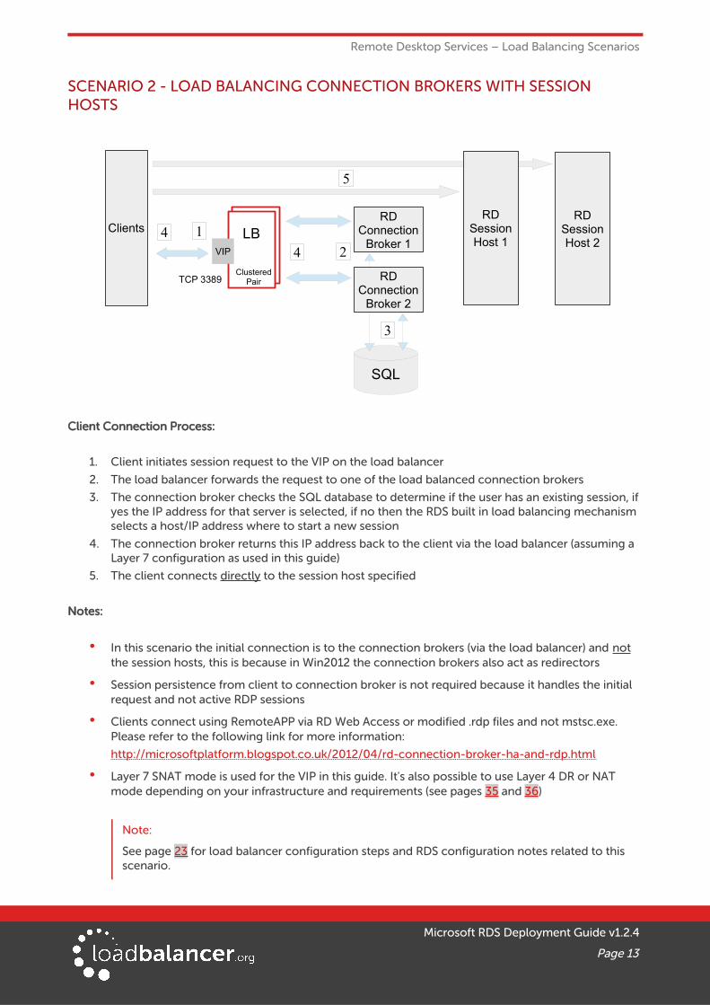
SCENARIO 2 - LOAD BALANCING CONNECTION BROKERS WITH SESSION HOSTS
Client Connection Process:
1. Client initiates session request to the VIP on the load balancer
2. The load balancer forwards the request to one of the load balanced connection brokers
3. The connection broker checks the SQL database to determine if the user has an existing session, if yes the IP address for that server is selected, if no then the RDS built in load balancing mechanism selects a host/IP address where to start a new session
4. The connection broker returns this IP address back to the client via the load balancer (assuming a Layer 7 configuration as used in this guide)
5. The client connects directly to the session host specified
Notes:
• In this scenario the initial connection is to the connection brokers (via the load balancer) and not the session hosts, this is because in Win2012 the connection brokers also act as redirectors
• Session persistence from client to connection broker is not required because it handles the initial request and not active RDP sessions
• Clients connect using RemoteAPP via RD Web Access or modified .rdp files and not mstsc.exe. Please refer to the following link for more information:
http://microsoftplatform.blogspot.co.uk/2012/04/rd-connection-broker-ha-and-rdp.html
• Layer 7 SNAT mode is used for the VIP in this guide. It's also possible to use Layer 4 DR or NAT mode depending on your infrastructure and requirements (see pages 35 and 36)
Note:
See page 23 for load balancer configuration steps and RDS configuration notes related to this scenario.
Microsoft RDS Deployment Guide v1.2.4
Page 13
LBLB
ClusteredPair
SQL
RDSessionHost 2
RDSessionHost 1
RDConnection
Broker 1Clients
24
14
5
RDConnection
Broker 2
VIP
3
TCP 3389

Remote Desktop Services – Load Balancing Scenarios
SCENARIO 3 - LOAD BALANCING CONNECTION BROKERS WITH VIRTUALIZATION HOSTS
Client Connection Process:
1. Client initiates session request to the VIP on the load balancer
2. The load balancer forwards the request to one of the load balanced connection brokers
3. The connection broker checks the SQL database to determine if the user has an existing session, if yes the IP address for that server is selected, if no then the RDS built in load balancing mechanism selects a host/IP address where to start a new session
4. The connection broker returns this IP address back to the client via the load balancer (assuming a Layer 7 configuration as used in this guide)
5. The client connects directly to the virtualization host specified
Notes:
• In this scenario the initial connection is to the connection brokers (via the load balancer) and not the virtualization hosts, this is because in Win2012 the connection brokers also act as redirectors
• Session persistence from client to connection broker is not required
• Clients connect using RemoteAPP via RD Web Access or modified .rdp files and not mstsc.exe. Please refer to the following link for more information:
http://microsoftplatform.blogspot.co.uk/2012/04/rd-connection-broker-ha-and-rdp.html
• Layer 7 SNAT mode is used for the VIP in this guide. It's also possible to use Layer 4 DR or NAT mode depending on your infrastructure and requirements (see pages 35 and 36)
Note:
See page 23 for load balancer configuration steps and RDS configuration notes related to this scenario.
Microsoft RDS Deployment Guide v1.2.4
Page 14
SQL
LBLB
ClusteredPair
RDVirtualization
Host 2
RDVirtualization
Host 1
RDConnection
Broker 1Clients
24
14
5
RDConnection
Broker 2
VIP
3
TCP 3389

Remote Desktop Services – Load Balancing Scenarios
SCENARIO 4 - LOAD BALANCING SESSION HOSTS WHEN DEPLOYED WITH CONNECTION BROKER
Client Connection Process:
1. Client initiates session request to the VIP on the load balancer
2. The load balancer forwards the request to one of the load balanced session hosts
3. The session host checks with the active connection broker if the user has an existing session, if yesthe IP address for that server is encoded in a routing token
4. The routing token is returned via the load balancer to the client, the client then reconnects via the load balancer to the session host specified in the routing token
Note:
For detailed information on routing tokens and their format please refer to this document.
Notes:
• In this scenario the initial connection is to the session hosts which perform the client redirection
• One of the connection brokers must be configured as active (see page 25), active/active mode is only supported when used as part of a RD Gateway deployment (see pages 16)
• The session hosts must be configured in Routing Token Redirection Mode (see page 25)
• Session persistence from client to session host is based on routing token
• Layer 7 SNAT mode must be used for this configuration to enable the routing tokens to be read
• Clients connect using the Microsoft RDP client (mstsc.exe) or equivalent
Note:
See page 25 for load balancer configuration steps and RDS configuration notes.
Microsoft RDS Deployment Guide v1.2.4
Page 15
LB
SQL
RDSessionHost 2
RDSessionHost 1
RDConnection
Broker 1
Clients
2
3
14
4
RDConnection
Broker 2
VIP
3
TCP 3389 ClusteredPair
Remote Desktop Services – Load Balancing Scenarios
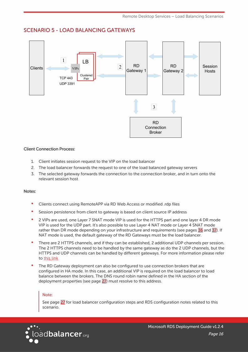
SCENARIO 5 - LOAD BALANCING GATEWAYS
Client Connection Process:
1. Client initiates session request to the VIP on the load balancer
2. The load balancer forwards the request to one of the load balanced gateway servers
3. The selected gateway forwards the connection to the connection broker, and in turn onto the relevant session host
Notes:
• Clients connect using RemoteAPP via RD Web Access or modified .rdp files
• Session persistence from client to gateway is based on client source IP address
• 2 VIPs are used, one Layer 7 SNAT mode VIP is used for the HTTPS part and one layer 4 DR mode VIP is used for the UDP part. It's also possible to use Layer 4 NAT mode or Layer 4 SNAT mode rather than DR mode depending on your infrastructure and requirements (see pages 36 and 37). If NAT mode is used, the default gateway of the RD Gateways must be the load balancer.
• There are 2 HTTPS channels, and if they can be established, 2 additional UDP channels per session.The 2 HTTPS channels need to be handled by the same gateway as do the 2 UDP channels, but theHTTPS and UDP channels can be handled by different gateways. For more information please referto this link
• The RD Gateway deployment can also be configured to use connection brokers that are configured in HA mode. In this case, an additional VIP is required on the load balancer to load balance between the brokers. The DNS round robin name defined in the HA section of the deployment properties (see page 27) must resolve to this address.
Note:
See page 27 for load balancer configuration steps and RDS configuration notes related to this scenario.
Microsoft RDS Deployment Guide v1.2.4
Page 16
RDGateway 2
Clients RDGateway 1
TCP 443
UDP 3391
12
3
RDConnection
Broker
SessionHosts
LB
ClusteredPair
VIPs
Remote Desktop Services – Load Balancing Scenarios
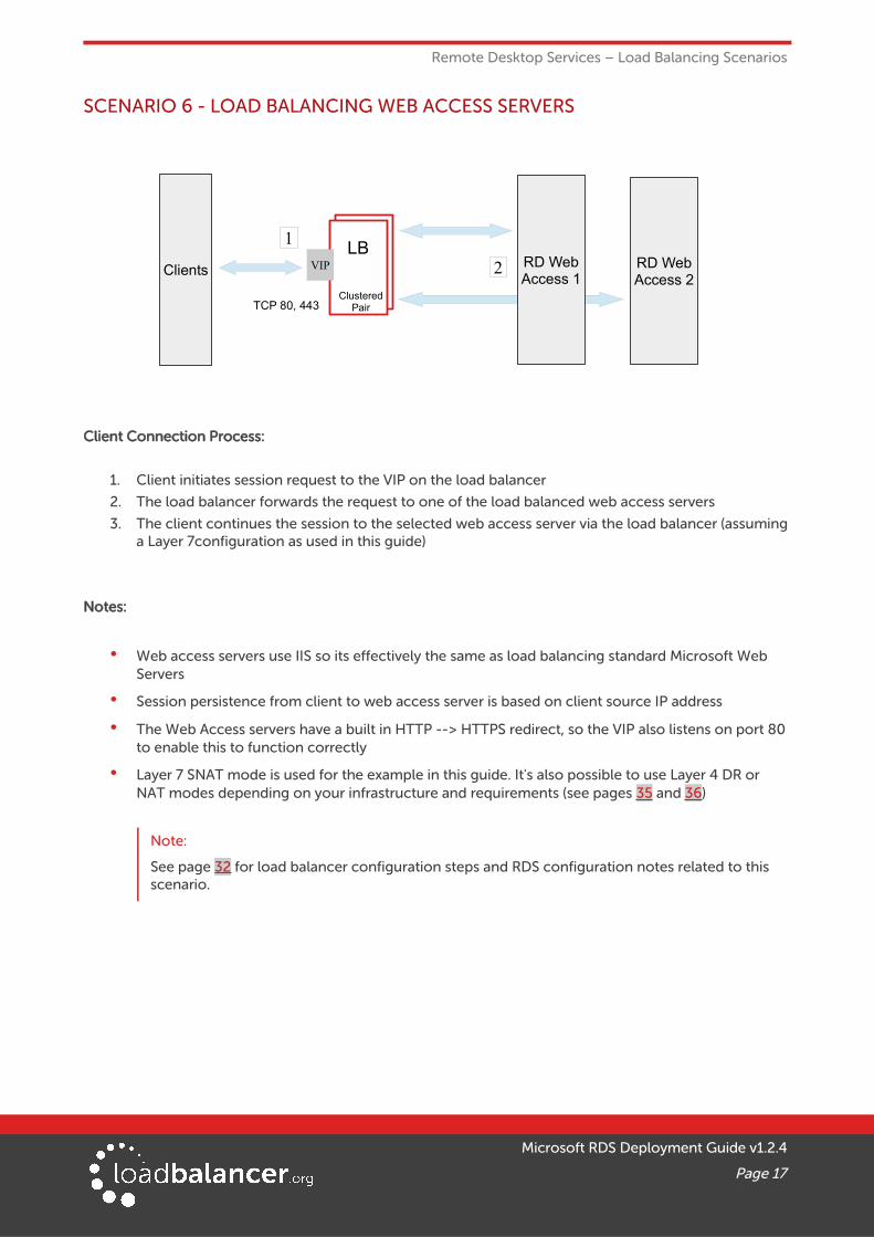
SCENARIO 6 - LOAD BALANCING WEB ACCESS SERVERS
Client Connection Process:
1. Client initiates session request to the VIP on the load balancer
2. The load balancer forwards the request to one of the load balanced web access servers
3. The client continues the session to the selected web access server via the load balancer (assuminga Layer 7configuration as used in this guide)
Notes:
• Web access servers use IIS so its effectively the same as load balancing standard Microsoft Web Servers
• Session persistence from client to web access server is based on client source IP address
• The Web Access servers have a built in HTTP --> HTTPS redirect, so the VIP also listens on port 80 to enable this to function correctly
• Layer 7 SNAT mode is used for the example in this guide. It's also possible to use Layer 4 DR or NAT modes depending on your infrastructure and requirements (see pages 35 and 36)
Note:
See page 32 for load balancer configuration steps and RDS configuration notes related to this scenario.
Microsoft RDS Deployment Guide v1.2.4
Page 17
RD WebAccess 2
Clients RD WebAccess 1
TCP 80, 443
1
2LB
ClusteredPair
VIP

Loadbalancer.org Appliance – the Basics
8. Loadbalancer.org Appliance – the Basics
VIRTUAL APPLIANCE DOWNLOAD & DEPLOYMENTA fully featured, fully supported 30 day trial is available if you are conducting a PoC (Proof of Concept) deployment. The VA is currently available for VMware, Virtual Box, Hyper-V, KVM and XEN and has been optimized for each Hypervisor. By default, the VA is allocated 1 CPU, 2GB of RAM and has an 8GB virtual disk. The Virtual Appliance can be downloaded here.
Note:
The same download is used for the licensed product, the only difference is that a license key file(supplied by our sales team when the product is purchased) must be applied using the appliance's WebUI.
Note:
Please refer to the Administration Manual and the ReadMe.txt text file included in the VA download for more detailed information on deploying the VA using various Hypervisors.
INITIAL NETWORK CONFIGURATIONThe IP address, subnet mask, default gateway and DNS settings can be configured in several ways as detailed below:
Method 1 - Using the Network Setup Wizard at the console
After boot up, follow the instructions on the console to configure the IP address, subnet mask, default gateway and DNS settings.
Method 2 - Using the WebUI
Using a browser, connect to the WebUI on the default IP address/port: http://192.168.2.21:9080
To set the IP address & subnet mask, use: Local Configuration > Network Interface Configuration
To set the default gateway, use: Local Configuration > Routing
To configure DNS settings, use: Local Configuration > Hostname & DNS
Method 3 - Using Linux commands
At the console, set the initial IP address using the following command:
ip addr add <IP address>/<mask> dev eth0
At the console, set the initial default gateway using the following command:
route add default gw <IP address> <interface>
At the console, set the DNS server using the following command:
echo nameserver <IP address> >> /etc/resolv.conf
Note:
If method 3 is used, you must also configure these settings using the WebUI, otherwise the settings will be lost after a reboot
Microsoft RDS Deployment Guide v1.2.4
Page 18
Loadbalancer.org Appliance – the Basics
ACCESSING THE WEB USER INTERFACE (WEBUI)The WebUI can be accessed via HTTP at the following URL: http://192.168.2.21:9080/lbadmin
* Note the port number → 9080
The WebUI can be accessed via HTTPS at the following URL: https://192.168.2.21:9443/lbadmin
* Note the port number → 9443
(replace 192.168.2.21 with the IP address of your load balancer if it's been changed from the default)
Login using the following credentials:
Username: loadbalancer
Password: loadbalancer
Note:
To change the password , use the WebUI menu option: Maintenance > Passwords.
Once logged in, the WebUI will be displayed as shown on the following page:
Microsoft RDS Deployment Guide v1.2.4
Page 19
Loadbalancer.org Appliance – the Basics
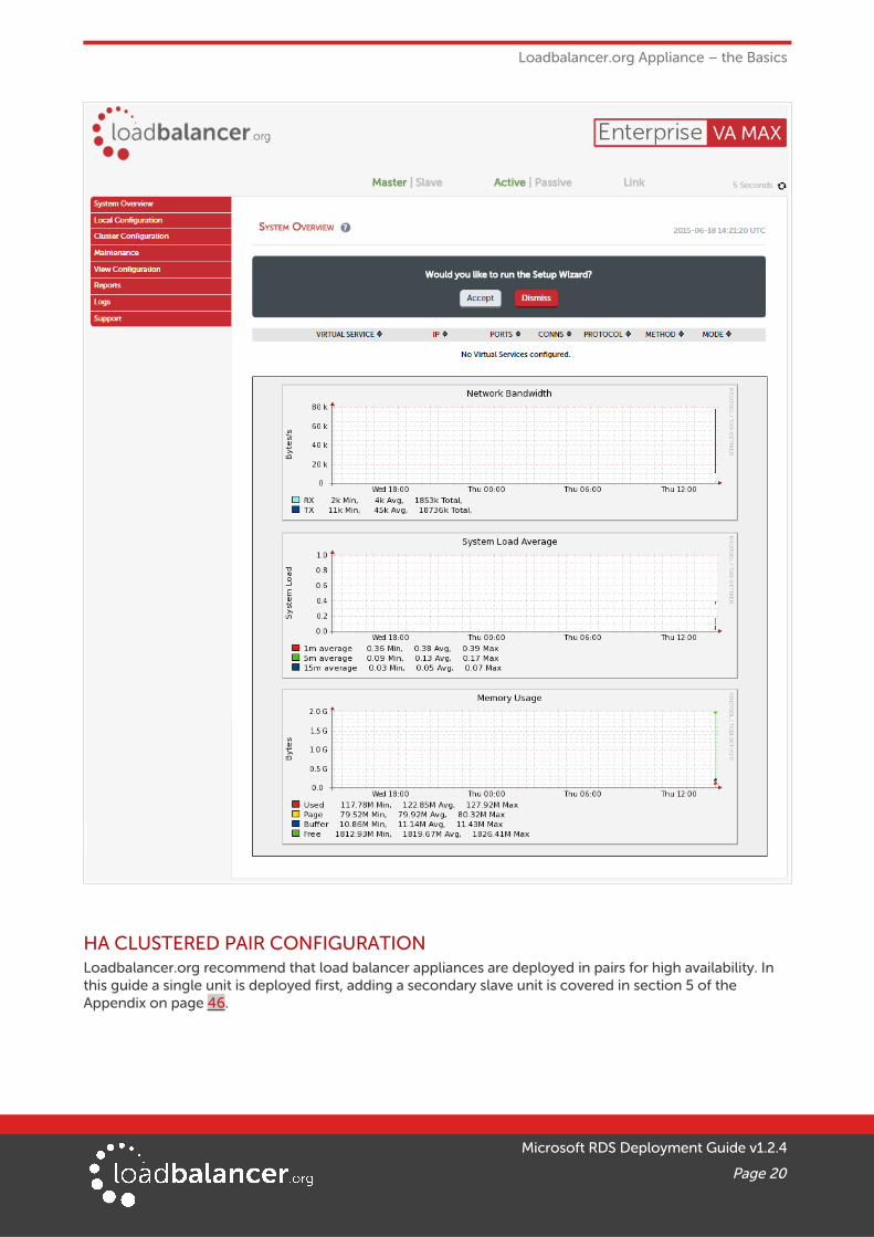
HA CLUSTERED PAIR CONFIGURATIONLoadbalancer.org recommend that load balancer appliances are deployed in pairs for high availability. In this guide a single unit is deployed first, adding a secondary slave unit is covered in section 5 of the Appendix on page 46.
Microsoft RDS Deployment Guide v1.2.4
Page 20

Load Balancing Session Hosts Deployed without Connection Broker (Scenario 1)
9. Load Balancing Session Hosts Deployed without Connection Broker (Scenario 1)
Please refer to page 12 for a deployment diagram and notes on how the load balancer interacts with RDS.
RDS INSTALLATION & CONFIGURATION
• Use the Role-based or feature-based installation type to install the Session Host service on multiple servers
• Session management on Windows 2008 hosts is via Remote Desktop Services Manager
• In this scenario, session management on Windows 2012 hosts is not possible using graphical tools,only Powershell. However, Remote Desktop Services Manager on Windows 2008/Windows 7 (Remote Server Administration Tools for Windows 7) can also be used to manage Window 2012 hosts
APPLIANCE CONFIGURATION
SETTING UP THE VIRTUAL SERVICE (VIP)
1. Using the WebUI, navigate to: Cluster Configuration > Layer 7 – Virtual Services and click Add a New Virtual Service
2. Enter the following details:
3. Enter an appropriate name (Label) for the Virtual Service, e.g. SH-Cluster
4. Set the Virtual Service IP address field to the required IP address, e.g. 192.168.2.100
5. Set the Virtual Service Ports field to 3389
6. Set the Layer 7 Protocol to TCP Mode
7. Click Update
8. Now click Modify next to the newly created Virtual Service
9. Configure the required Persistence Mode:
• If you want to use the client source IP address to maintain client to server persistence, ensure Persistence Mode is set to Source IP
• If you want to use RDP cookies to maintain client to server persistence, ensure Persistence Mode is set to RDP Client Cookie
10. Set Persistence Timeout to an appropriate value, e.g. 120 (i.e. 2 hours)
Microsoft RDS Deployment Guide v1.2.4
Page 21
Load Balancing Session Hosts Deployed without Connection Broker (Scenario 1)
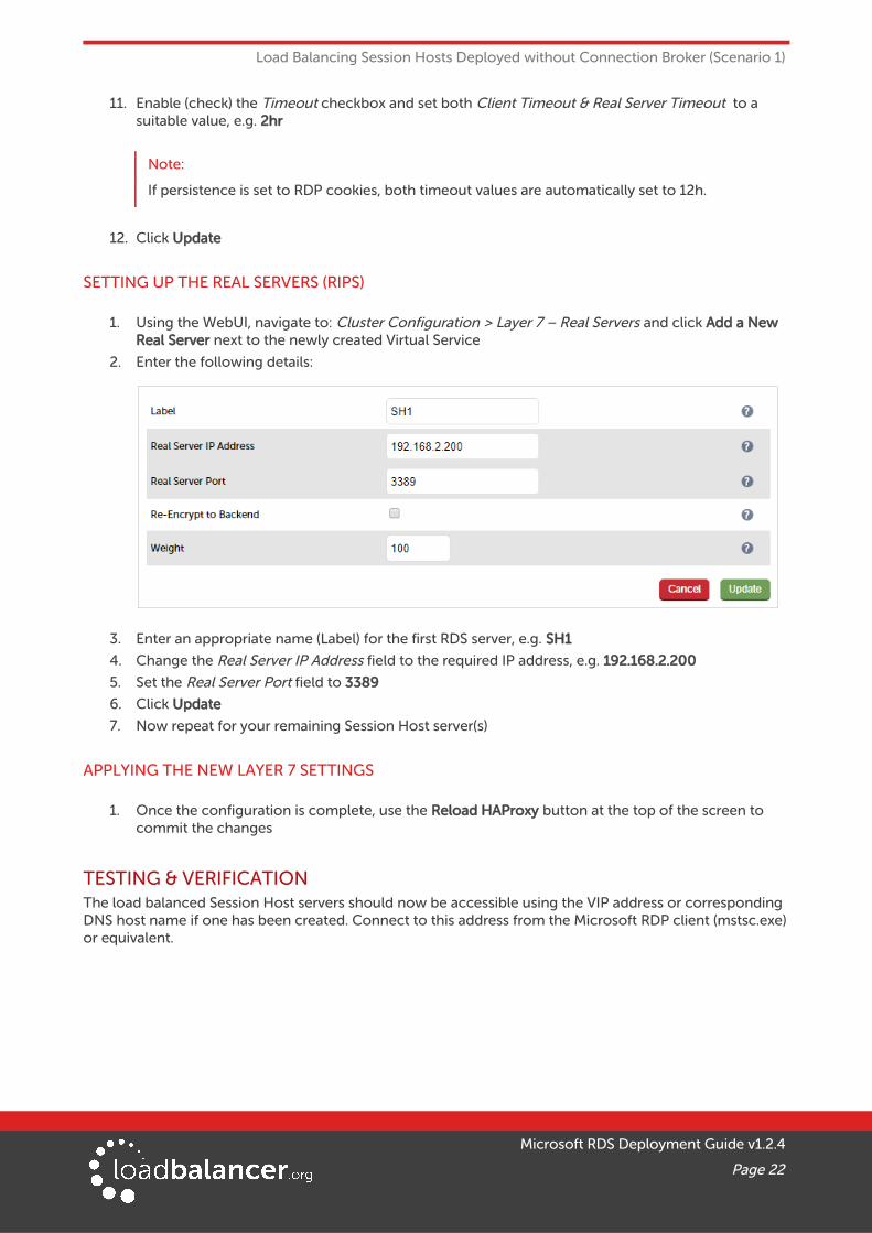
11. Enable (check) the Timeout checkbox and set both Client Timeout & Real Server Timeout to a suitable value, e.g. 2hr
Note:
If persistence is set to RDP cookies, both timeout values are automatically set to 12h.
12. Click Update
SETTING UP THE REAL SERVERS (RIPS)
1. Using the WebUI, navigate to: Cluster Configuration > Layer 7 – Real Servers and click Add a New Real Server next to the newly created Virtual Service
2. Enter the following details:
3. Enter an appropriate name (Label) for the first RDS server, e.g. SH1
4. Change the Real Server IP Address field to the required IP address, e.g. 192.168.2.200
5. Set the Real Server Port field to 3389
6. Click Update
7. Now repeat for your remaining Session Host server(s)
APPLYING THE NEW LAYER 7 SETTINGS
1. Once the configuration is complete, use the Reload HAProxy button at the top of the screen to commit the changes
TESTING & VERIFICATIONThe load balanced Session Host servers should now be accessible using the VIP address or corresponding DNS host name if one has been created. Connect to this address from the Microsoft RDP client (mstsc.exe)or equivalent.
Microsoft RDS Deployment Guide v1.2.4
Page 22
Load Balancing Connection Brokers (Scenario's 2 & 3)
10. Load Balancing Connection Brokers (Scenario's 2 & 3)
Please refer to pages 13 & 14 for a deployment diagram and notes on how the load balancer interacts with RDS.
RDS INSTALLATION & CONFIGURATION
• Use the Remote Desktop Services installation type to install Connection Broker, Web Access and Session Host/Virtualization Host role services to the relevant RDS servers
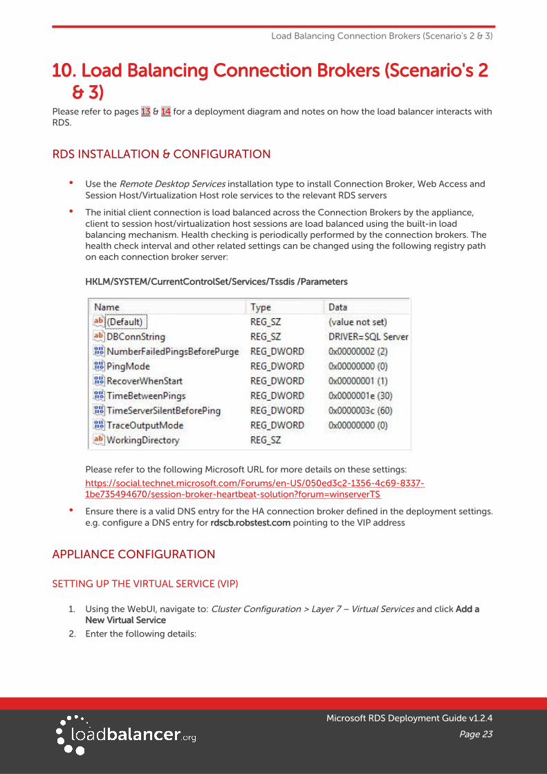
• The initial client connection is load balanced across the Connection Brokers by the appliance, client to session host/virtualization host sessions are load balanced using the built-in load balancing mechanism. Health checking is periodically performed by the connection brokers. The health check interval and other related settings can be changed using the following registry path on each connection broker server:
HKLM/SYSTEM/CurrentControlSet/Services/Tssdis /Parameters
Please refer to the following Microsoft URL for more details on these settings:
https://social.technet.microsoft.com/Forums/en-US/050ed3c2-1356-4c69-8337-1be735494670/session-broker-heartbeat-solution?forum=winserverTS
• Ensure there is a valid DNS entry for the HA connection broker defined in the deployment settings.e.g. configure a DNS entry for rdscb.robstest.com pointing to the VIP address
APPLIANCE CONFIGURATION
SETTING UP THE VIRTUAL SERVICE (VIP)
1. Using the WebUI, navigate to: Cluster Configuration > Layer 7 – Virtual Services and click Add a New Virtual Service
2. Enter the following details:
Microsoft RDS Deployment Guide v1.2.4
Page 23
Load Balancing Connection Brokers (Scenario's 2 & 3)
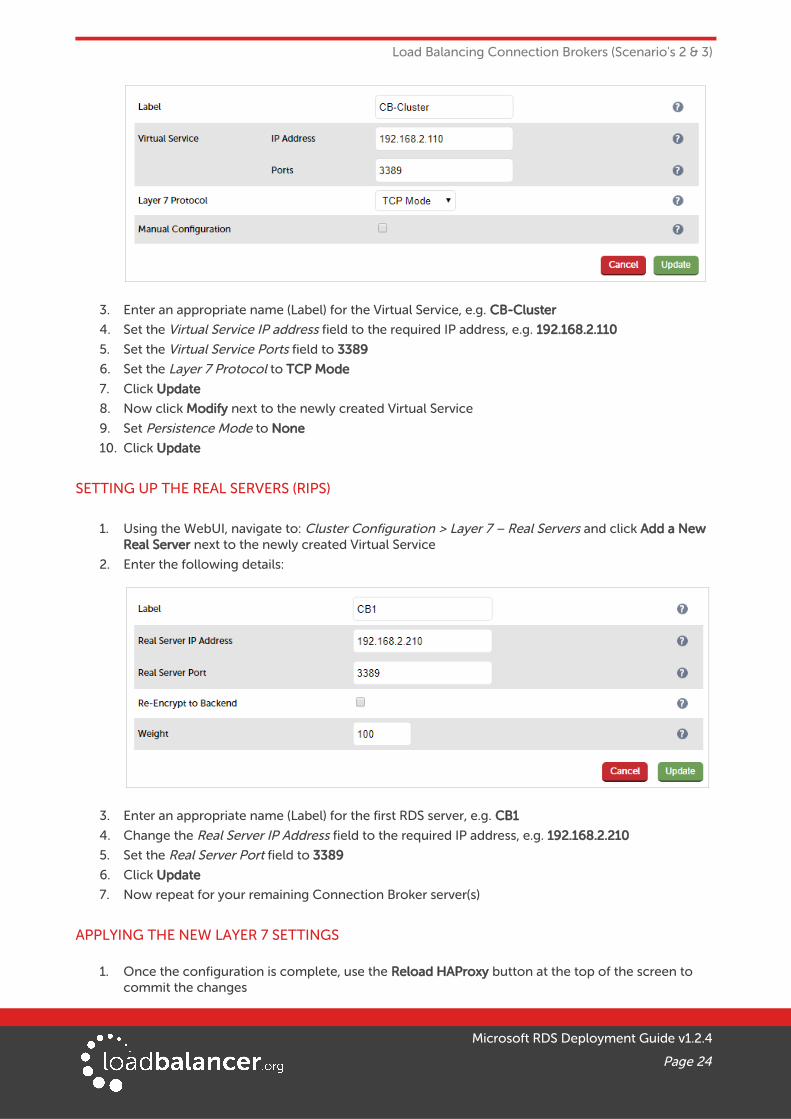
3. Enter an appropriate name (Label) for the Virtual Service, e.g. CB-Cluster
4. Set the Virtual Service IP address field to the required IP address, e.g. 192.168.2.110
5. Set the Virtual Service Ports field to 3389
6. Set the Layer 7 Protocol to TCP Mode
7. Click Update
8. Now click Modify next to the newly created Virtual Service
9. Set Persistence Mode to None
10. Click Update
SETTING UP THE REAL SERVERS (RIPS)
1. Using the WebUI, navigate to: Cluster Configuration > Layer 7 – Real Servers and click Add a New Real Server next to the newly created Virtual Service
2. Enter the following details:
3. Enter an appropriate name (Label) for the first RDS server, e.g. CB1
4. Change the Real Server IP Address field to the required IP address, e.g. 192.168.2.210
5. Set the Real Server Port field to 3389
6. Click Update
7. Now repeat for your remaining Connection Broker server(s)
APPLYING THE NEW LAYER 7 SETTINGS
1. Once the configuration is complete, use the Reload HAProxy button at the top of the screen to commit the changes
Microsoft RDS Deployment Guide v1.2.4
Page 24
Load Balancing Connection Brokers (Scenario's 2 & 3)
TESTING & VERIFICATIONThe load balanced Connection Broker servers should now be accessible via the DNS address. Use Web Access/RemoteAPP or a manually modified .rdp file to verify that published applications are available.
As mentioned, ensure there is a valid DNS entry for the HA connection broker defined in the deployment settings. In this example it should be rdscb.robstest.com pointing to 192.168.2.110.
11. Load Balancing Session Hosts when Deployed with Connection Broker (Scenario 4)
Please refer to page 15 for a deployment diagram and notes on how the load balancer interacts with RDS.
RDS INSTALLATION & CONFIGURATION
• Use the Remote Desktop Services installation type to install Connection Broker, Web Access and Session Host Host role services to the relevant RDS servers
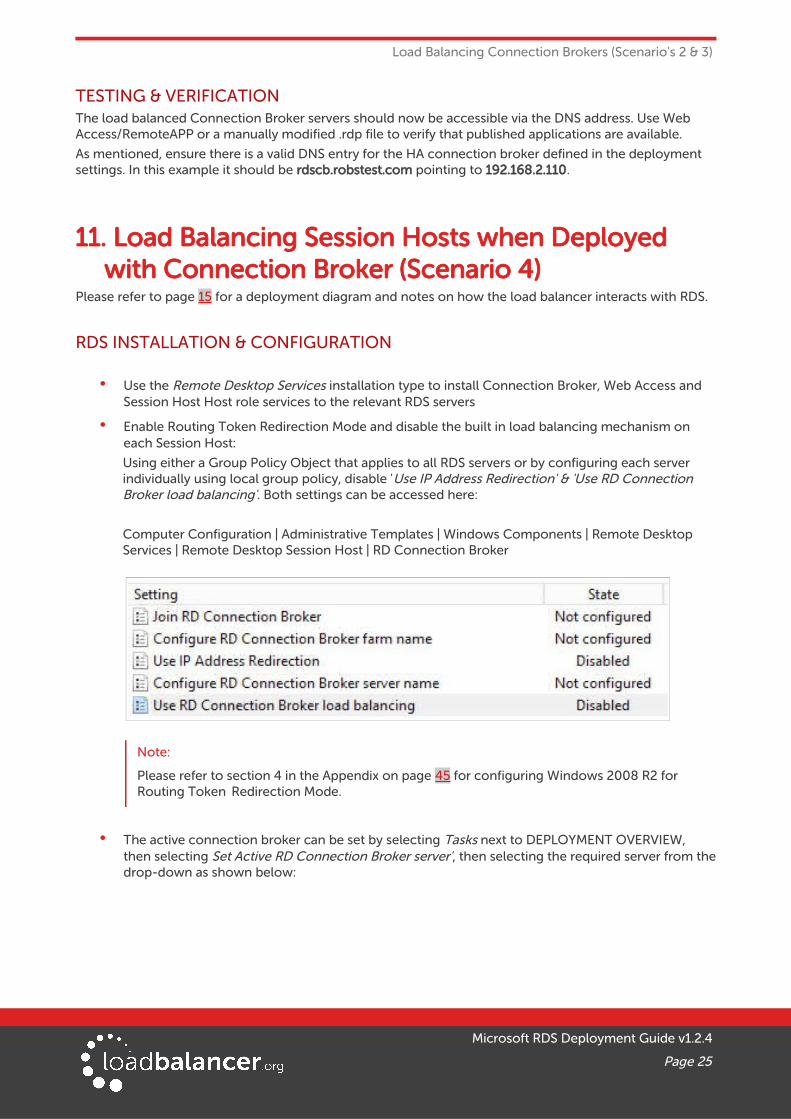
• Enable Routing Token Redirection Mode and disable the built in load balancing mechanism on each Session Host:
Using either a Group Policy Object that applies to all RDS servers or by configuring each server individually using local group policy, disable 'Use IP Address Redirection' & 'Use RD Connection Broker load balancing'. Both settings can be accessed here:
Computer Configuration | Administrative Templates | Windows Components | Remote Desktop Services | Remote Desktop Session Host | RD Connection Broker
Note:
Please refer to section 4 in the Appendix on page 45 for configuring Windows 2008 R2 for Routing Token Redirection Mode.
• The active connection broker can be set by selecting Tasks next to DEPLOYMENT OVERVIEW, then selecting Set Active RD Connection Broker server', then selecting the required server from thedrop-down as shown below:
Microsoft RDS Deployment Guide v1.2.4
Page 25

Load Balancing Session Hosts when Deployed with Connection Broker (Scenario 4)
APPLIANCE CONFIGURATION
SETTING UP THE VIRTUAL SERVICE (VIP)
1. Using the WebUI, navigate to: Cluster Configuration > Layer 7 – Virtual Services and click Add a New Virtual Service
2. Enter the following details:
3. Enter an appropriate name (Label) for the Virtual Service, e.g. SH-Cluster
4. Set the Virtual Service IP address field to the required IP address, e.g. 192.168.2.100
5. Set the Virtual Service Ports field to 3389
6. Set the Layer 7 Protocol to TCP Mode
7. Click Update
8. Now click Modify next to the newly created Virtual Service
9. Ensure Persistence Mode is set to MS Session Broker
10. Enable (check) the Timeout checkbox and set both Client & Real Server Timeout to 2h (i.e. 2 hours)
11. Click Update
SETTING UP THE REAL SERVERS (RIPS)
1. Using the WebUI, navigate to: Cluster Configuration > Layer 7 – Real Servers and click Add a New Real Server next to the newly created Virtual Service
2. Enter the following details:
Microsoft RDS Deployment Guide v1.2.4
Page 26
Load Balancing Session Hosts when Deployed with Connection Broker (Scenario 4)
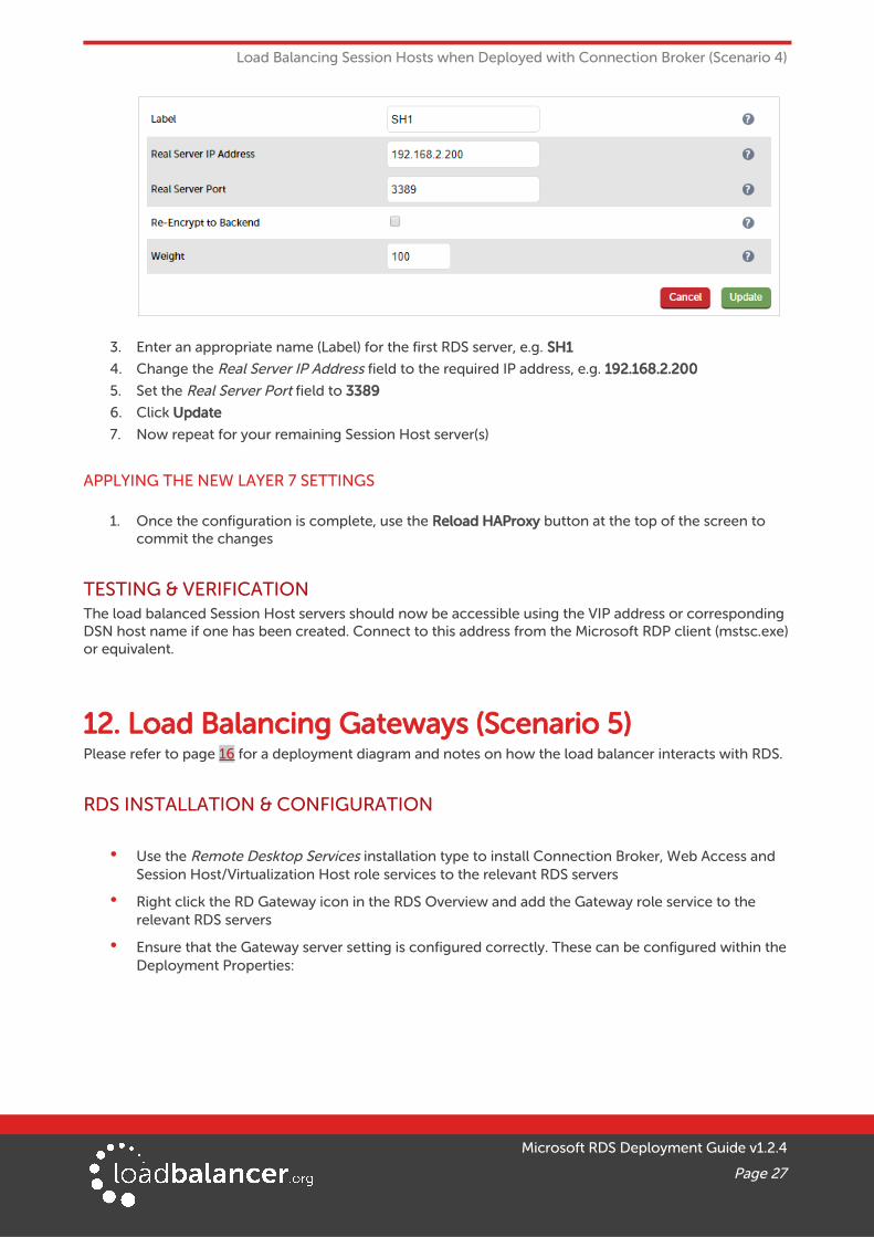
3. Enter an appropriate name (Label) for the first RDS server, e.g. SH1
4. Change the Real Server IP Address field to the required IP address, e.g. 192.168.2.200
5. Set the Real Server Port field to 3389
6. Click Update
7. Now repeat for your remaining Session Host server(s)
APPLYING THE NEW LAYER 7 SETTINGS
1. Once the configuration is complete, use the Reload HAProxy button at the top of the screen to commit the changes
TESTING & VERIFICATIONThe load balanced Session Host servers should now be accessible using the VIP address or corresponding DSN host name if one has been created. Connect to this address from the Microsoft RDP client (mstsc.exe)or equivalent.
12. Load Balancing Gateways (Scenario 5)Please refer to page 16 for a deployment diagram and notes on how the load balancer interacts with RDS.
RDS INSTALLATION & CONFIGURATION
• Use the Remote Desktop Services installation type to install Connection Broker, Web Access and Session Host/Virtualization Host role services to the relevant RDS servers
• Right click the RD Gateway icon in the RDS Overview and add the Gateway role service to the relevant RDS servers
• Ensure that the Gateway server setting is configured correctly. These can be configured within the Deployment Properties:
Microsoft RDS Deployment Guide v1.2.4
Page 27

Load Balancing Gateways (Scenario 5)
• Create a DNS record with the same name (rd-gateway.robstest.com in the above example) that points to the load balanced Gateway VIP (see page 29 for details on configuring this VIP)
• If using multiple connection brokers, ensure that the HA settings are configured correctly within the Deployment Properties:
The DNS round robin name (rdscb.robstest.com in the above example) is used by the Gateway servers to connect to the load balanced connection brokers. Create a DNS record with the same name that points to the load balanced Connection Broker VIP (see page 32 for details on configuring this VIP)
• Ensure that the Remote Authorization Policy policies permits connections to the session host servers and the DNS round robin HA name (if HA mode is used) as shown below:
Microsoft RDS Deployment Guide v1.2.4
Page 28

Load Balancing Gateways (Scenario 5)
• Ensure that all load balanced gateway servers are members of the same RD Gateway server farm as shown in the example below:
• Now refer to section 2 in the Appendix on page 39 to ensure that each gateway server is able to receive packets destined for the VIP address and that the servers do not respond to ARP requests for this IP address - this is known as Solving the ARP problem and must be done when using layer 4 DR mode. This step is only required if you'll be configuring UDP for your Gateway Servers
Note:
If Layer 4 NAT mode or layer 4 SNAT mode is used for load balancing the UDP for the Gateways rather than DR mode, there is no need to solve the ARP problem. If layer 4 NAT modeis used, the default gateway of the RD Gateways must be the load balancer.
APPLIANCE CONFIGURATIONTwo VIPs are required – one for the TCP/HTTPS component on port 443, the second is the for the UDP component on port 3391. Both VIPs are configured on the same IP address.
SETTING UP THE HTTPS VIRTUAL SERVICE (VIP)
Microsoft RDS Deployment Guide v1.2.4
Page 29
Load Balancing Gateways (Scenario 5)
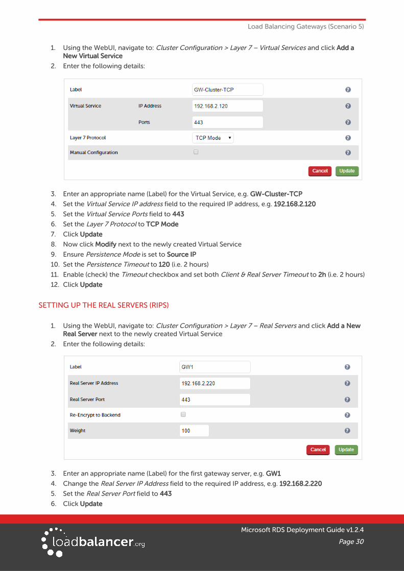
1. Using the WebUI, navigate to: Cluster Configuration > Layer 7 – Virtual Services and click Add a New Virtual Service
2. Enter the following details:
3. Enter an appropriate name (Label) for the Virtual Service, e.g. GW-Cluster-TCP
4. Set the Virtual Service IP address field to the required IP address, e.g. 192.168.2.120
5. Set the Virtual Service Ports field to 443
6. Set the Layer 7 Protocol to TCP Mode
7. Click Update
8. Now click Modify next to the newly created Virtual Service
9. Ensure Persistence Mode is set to Source IP
10. Set the Persistence Timeout to 120 (i.e. 2 hours)
11. Enable (check) the Timeout checkbox and set both Client & Real Server Timeout to 2h (i.e. 2 hours)
12. Click Update
SETTING UP THE REAL SERVERS (RIPS)
1. Using the WebUI, navigate to: Cluster Configuration > Layer 7 – Real Servers and click Add a New Real Server next to the newly created Virtual Service
2. Enter the following details:
3. Enter an appropriate name (Label) for the first gateway server, e.g. GW1
4. Change the Real Server IP Address field to the required IP address, e.g. 192.168.2.220
5. Set the Real Server Port field to 443
6. Click Update
Microsoft RDS Deployment Guide v1.2.4
Page 30
Load Balancing Gateways (Scenario 5)
7. Now repeat for your remaining Gateway server(s)
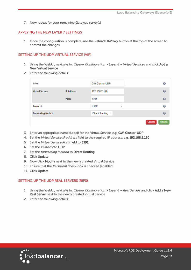
APPLYING THE NEW LAYER 7 SETTINGS
1. Once the configuration is complete, use the Reload HAProxy button at the top of the screen to commit the changes
SETTING UP THE UDP VIRTUAL SERVICE (VIP)
1. Using the WebUI, navigate to: Cluster Configuration > Layer 4 – Virtual Services and click Add a New Virtual Service
2. Enter the following details:
3. Enter an appropriate name (Label) for the Virtual Service, e.g. GW-Cluster-UDP
4. Set the Virtual Service IP address field to the required IP address, e.g. 192.168.2.120
5. Set the Virtual Service Ports field to 3391
6. Set the Protocol to UDP
7. Set the forwarding Method to Direct Routing
8. Click Update
9. Now click Modify next to the newly created Virtual Service
10. Ensure that the Persistent check-box is checked (enabled)
11. Click Update
SETTING UP THE UDP REAL SERVERS (RIPS)
1. Using the WebUI, navigate to: Cluster Configuration > Layer 4 – Real Servers and click Add a New Real Server next to the newly created Virtual Service
2. Enter the following details:
Microsoft RDS Deployment Guide v1.2.4
Page 31

Load Balancing Gateways (Scenario 5)
3. Enter an appropriate name (Label) for the first gateway server, e.g. GW1
4. Change the Real Server IP Address field to the required IP address, e.g. 192.168.2.220
5. Leave other values at the default values
6. Click Update
7. Now repeat for your remaining Gateway server(s)
SETTING UP THE CONNECTION BROKER VIRTUAL SERVICE (VIP)If more than one connection broker is used in HA mode, an additional VIP is required. Follow the steps in the section titled Load Balancer Configuration on page 23 , changing the IP address as needed.
TESTING & VERIFICATIONThe load balanced gateway servers should now be accessible via the DNS address. Use Web Access/RemoteAPP or a manually modified .rdp file to verify that published applications are available via the gateway
As mentioned, ensure there is a valid DNS entry for the HA connection broker defined in the deployment settings. In this example is should be the load balanced broker address: rdscb.robstest.com pointing to 192.168.2.110
As mentioned, ensure there is a valid DNS entry for the RD gateway server defined in the deployment settings. In this example is should be the load balanced gateway address: rd-gateway.robstest.com pointing to 192.168.2.120
13. Load Balancing Web Access Servers (Scenario 6)Please refer to page 17 for a deployment diagram and notes on how the load balancer interacts with RDS.
RDS INSTALLATION & CONFIGURATION
• Use the Remote Desktop Services installation type to install Connection Broker, Web Access and Session Host/Virtualization Host role services to the relevant RDS servers
APPLIANCE CONFIGURATION
SETTING UP THE VIRTUAL SERVICE (VIP)
1. Using the WebUI, navigate to: Cluster Configuration > Layer 7 – Virtual Services and click Add a
Microsoft RDS Deployment Guide v1.2.4
Page 32
Load Balancing Web Access Servers (Scenario 6)
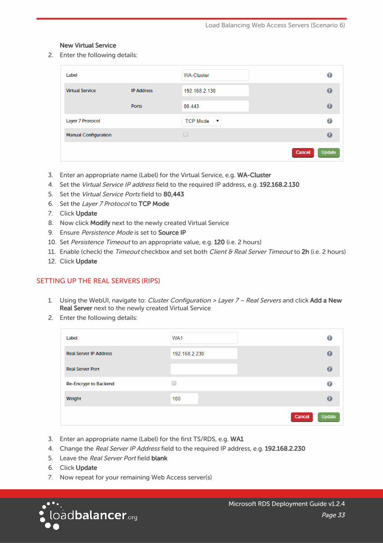
New Virtual Service
2. Enter the following details:
3. Enter an appropriate name (Label) for the Virtual Service, e.g. WA-Cluster
4. Set the Virtual Service IP address field to the required IP address, e.g. 192.168.2.130
5. Set the Virtual Service Ports field to 80,443
6. Set the Layer 7 Protocol to TCP Mode
7. Click Update
8. Now click Modify next to the newly created Virtual Service
9. Ensure Persistence Mode is set to Source IP
10. Set Persistence Timeout to an appropriate value, e.g. 120 (i.e. 2 hours)
11. Enable (check) the Timeout checkbox and set both Client & Real Server Timeout to 2h (i.e. 2 hours)
12. Click Update
SETTING UP THE REAL SERVERS (RIPS)
1. Using the WebUI, navigate to: Cluster Configuration > Layer 7 – Real Servers and click Add a New Real Server next to the newly created Virtual Service
2. Enter the following details:
3. Enter an appropriate name (Label) for the first TS/RDS, e.g. WA1
4. Change the Real Server IP Address field to the required IP address, e.g. 192.168.2.230
5. Leave the Real Server Port field blank
6. Click Update
7. Now repeat for your remaining Web Access server(s)
Microsoft RDS Deployment Guide v1.2.4
Page 33

Load Balancing Web Access Servers (Scenario 6)
APPLYING THE NEW LAYER 7 SETTINGS
1. Once the configuration is complete, use the Reload HAProxy button at the top of the screen to commit the changes
TESTING & VERIFICATIONThe load balanced Web Access servers should now be accessible using the VIP address or corresponding DNS entry if one has been created. Connect to this address from your browser.
In the case of the settings used here, the following URL would be used for RD Web Access:
https://192.168.2.130/RDweb
14. Technical SupportIf you have any questions regarding the appliance or would like assistance designing your deployment, please don't hesitate to contact our support team: [email protected].
15. Further DocumentationThe Administration Manual contains much more information about configuring and deploying the appliance. It's available here: http://pdfs.loadbalancer.org/loadbalanceradministrationv8.pdf
16. ConclusionLoadbalancer.org appliances provide a very cost effective and flexible solution for highly available load balanced Remote Desktop Services environments.
Microsoft RDS Deployment Guide v1.2.4
Page 34

Appendix
17. Appendix
1 - LOAD BALANCER DEPLOYMENT METHODSThe load balancer can be deployed in one of 4 fundamental ways; Layer 4 DR mode, Layer 4 NAT mode, Layer 4 SNAT mode or Layer 7 SNAT mode. These are described below.
LAYER 4 DR MODEOne-arm Direct Routing (DR) mode is a very high performance solution that requires little change to your existing infrastructure.
• DR mode works by changing the destination MAC address of the incoming packet to match the selected Real Server on the fly which is very fast
• When the packet reaches the Real Server it expects the Real Server to own the Virtual Services IP address (VIP). This means that you need to ensure that the Real Server (and the load balanced application) respond to both the Real Servers own IP address and the VIP
• The Real Server should not respond to ARP requests for the VIP. Only the load balancer should dothis. Configuring the Real Servers in this way is referred to as Solving the ARP Problem. Please referto page 39 for more details.
• On average, DR mode is 8 times quicker than NAT for HTTP, 50 times quicker for Terminal Services and much, much faster for streaming media or FTP
• The load balancer must have an Interface in the same subnet as the Real Servers to ensure layer 2 connectivity required for DR mode to work
• The VIP can be brought up on the same subnet as the Real Servers, or on a different subnet provided that the load balancer has an interface in that subnet
• Port translation is not possible in DR mode i.e. having a different RIP port than the VIP port
• DR mode is transparent, i.e. the Real Server will see the source IP address of the client
Note:
Layer 4 DR mode is used for the Gateway UDP requirement in this guide.
Microsoft RDS Deployment Guide v1.2.4
Page 35
Appendix
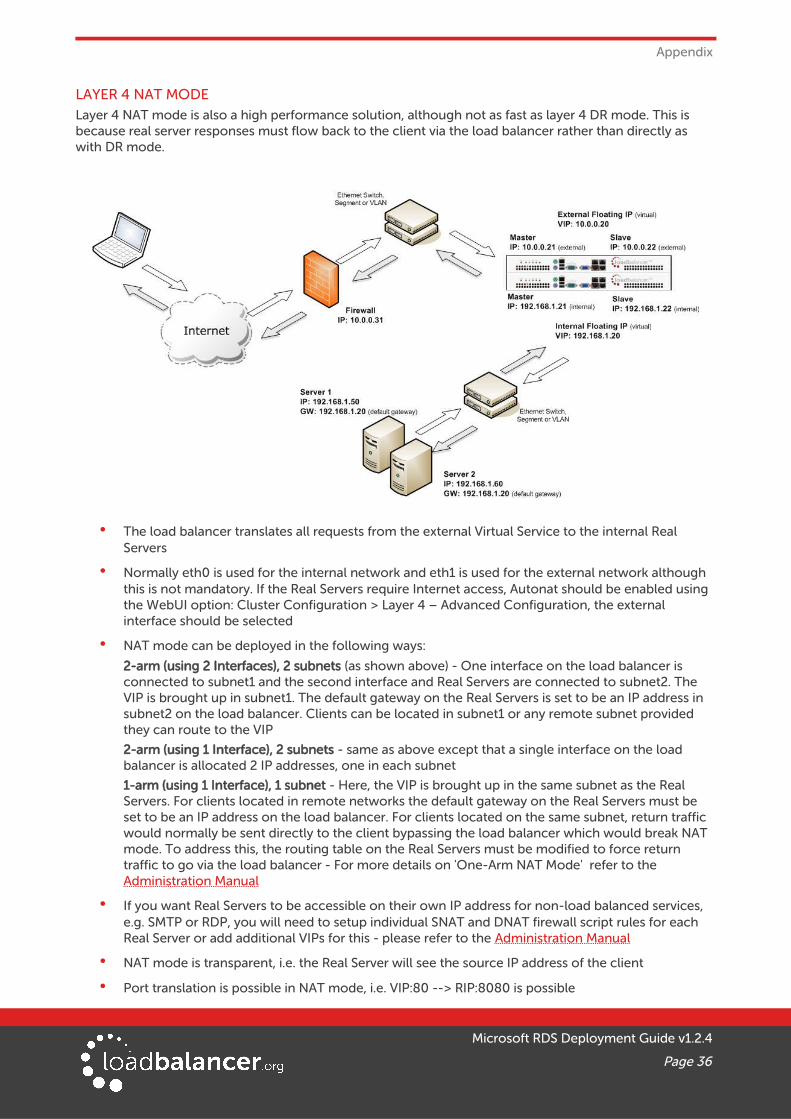
LAYER 4 NAT MODELayer 4 NAT mode is also a high performance solution, although not as fast as layer 4 DR mode. This is because real server responses must flow back to the client via the load balancer rather than directly as with DR mode.
• The load balancer translates all requests from the external Virtual Service to the internal Real Servers
• Normally eth0 is used for the internal network and eth1 is used for the external network although this is not mandatory. If the Real Servers require Internet access, Autonat should be enabled using the WebUI option: Cluster Configuration > Layer 4 – Advanced Configuration, the external interface should be selected
• NAT mode can be deployed in the following ways:
2-arm (using 2 Interfaces), 2 subnets (as shown above) - One interface on the load balancer is connected to subnet1 and the second interface and Real Servers are connected to subnet2. The VIP is brought up in subnet1. The default gateway on the Real Servers is set to be an IP address in subnet2 on the load balancer. Clients can be located in subnet1 or any remote subnet provided they can route to the VIP
2-arm (using 1 Interface), 2 subnets - same as above except that a single interface on the load balancer is allocated 2 IP addresses, one in each subnet
1-arm (using 1 Interface), 1 subnet - Here, the VIP is brought up in the same subnet as the Real Servers. For clients located in remote networks the default gateway on the Real Servers must be set to be an IP address on the load balancer. For clients located on the same subnet, return traffic would normally be sent directly to the client bypassing the load balancer which would break NAT mode. To address this, the routing table on the Real Servers must be modified to force return traffic to go via the load balancer - For more details on 'One-Arm NAT Mode' refer to the Administration Manual
• If you want Real Servers to be accessible on their own IP address for non-load balanced services, e.g. SMTP or RDP, you will need to setup individual SNAT and DNAT firewall script rules for each Real Server or add additional VIPs for this - please refer to the Administration Manual
• NAT mode is transparent, i.e. the Real Server will see the source IP address of the client
• Port translation is possible in NAT mode, i.e. VIP:80 --> RIP:8080 is possible
Microsoft RDS Deployment Guide v1.2.4
Page 36
Appendix
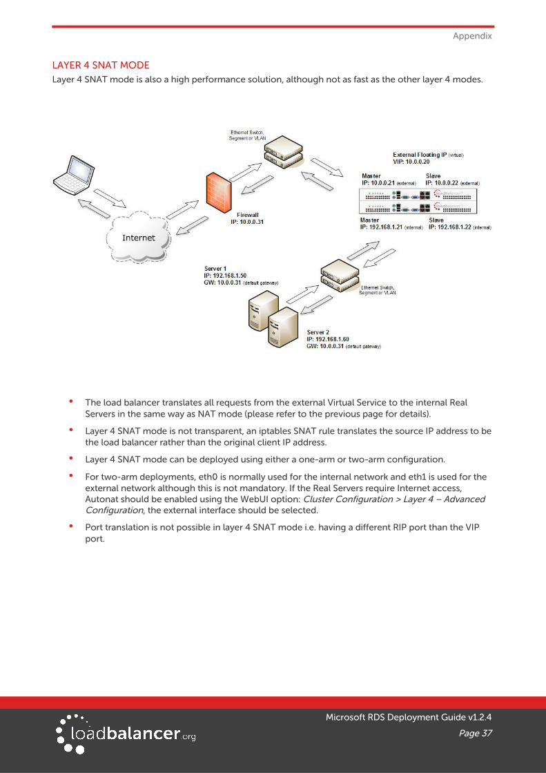
LAYER 4 SNAT MODELayer 4 SNAT mode is also a high performance solution, although not as fast as the other layer 4 modes.
• The load balancer translates all requests from the external Virtual Service to the internal Real Servers in the same way as NAT mode (please refer to the previous page for details).
• Layer 4 SNAT mode is not transparent, an iptables SNAT rule translates the source IP address to be the load balancer rather than the original client IP address.
• Layer 4 SNAT mode can be deployed using either a one-arm or two-arm configuration.
• For two-arm deployments, eth0 is normally used for the internal network and eth1 is used for the external network although this is not mandatory. If the Real Servers require Internet access, Autonat should be enabled using the WebUI option: Cluster Configuration > Layer 4 – Advanced Configuration, the external interface should be selected.
• Port translation is not possible in layer 4 SNAT mode i.e. having a different RIP port than the VIP port.
Microsoft RDS Deployment Guide v1.2.4
Page 37
Appendix
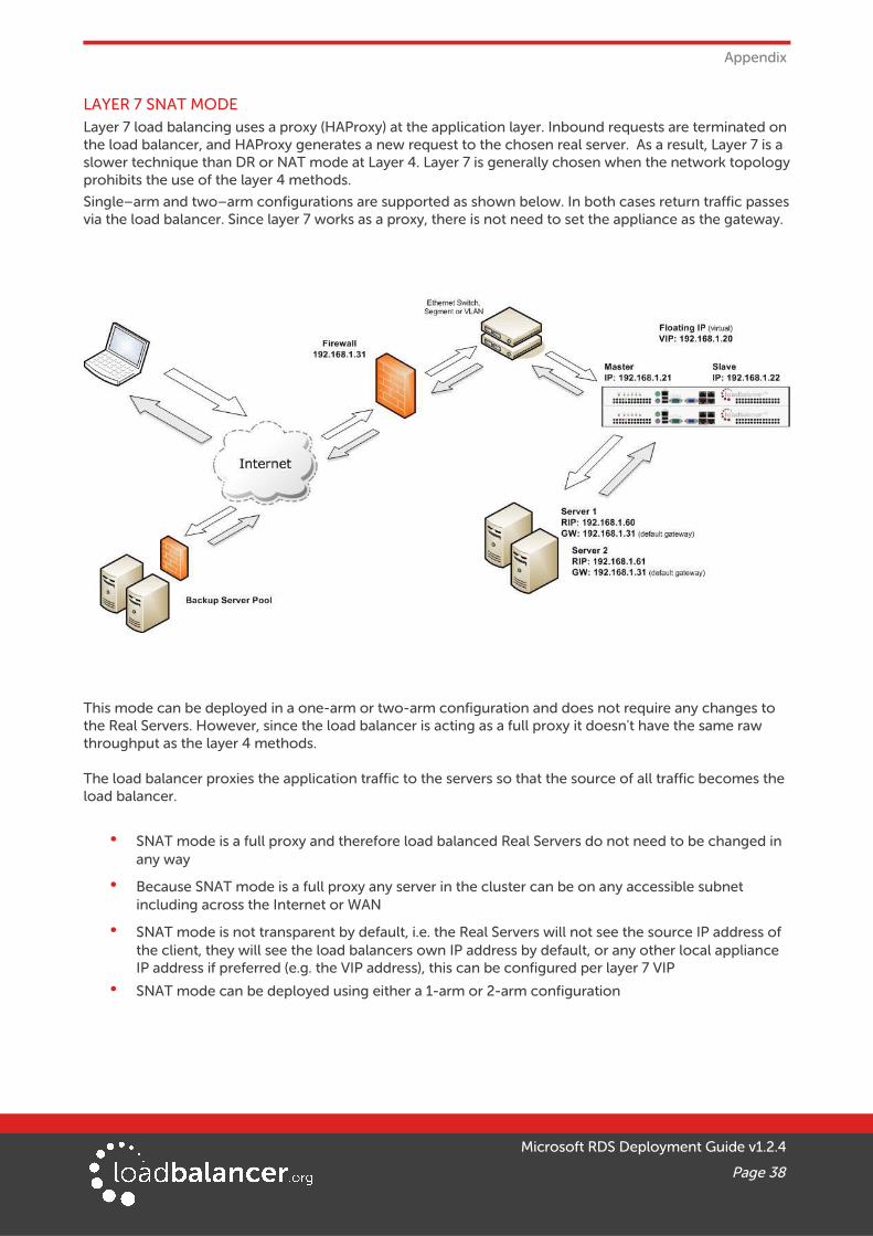
LAYER 7 SNAT MODELayer 7 load balancing uses a proxy (HAProxy) at the application layer. Inbound requests are terminated onthe load balancer, and HAProxy generates a new request to the chosen real server. As a result, Layer 7 is a slower technique than DR or NAT mode at Layer 4. Layer 7 is generally chosen when the network topologyprohibits the use of the layer 4 methods.
Single–arm and two–arm configurations are supported as shown below. In both cases return traffic passesvia the load balancer. Since layer 7 works as a proxy, there is not need to set the appliance as the gateway.
This mode can be deployed in a one-arm or two-arm configuration and does not require any changes to the Real Servers. However, since the load balancer is acting as a full proxy it doesn't have the same raw throughput as the layer 4 methods.
The load balancer proxies the application traffic to the servers so that the source of all traffic becomes the load balancer.
• SNAT mode is a full proxy and therefore load balanced Real Servers do not need to be changed in any way
• Because SNAT mode is a full proxy any server in the cluster can be on any accessible subnet including across the Internet or WAN
• SNAT mode is not transparent by default, i.e. the Real Servers will not see the source IP address of the client, they will see the load balancers own IP address by default, or any other local appliance IP address if preferred (e.g. the VIP address), this can be configured per layer 7 VIP
• SNAT mode can be deployed using either a 1-arm or 2-arm configuration
Microsoft RDS Deployment Guide v1.2.4
Page 38

Appendix
2 - SOLVING THE ARP PROBLEMWhen using Layer 4 DR mode, the ARP problem must be solved. This involves configuring each Real Serverto be able to receive traffic destined for the VIP, and ensuring that each Real Server does not respond to ARP requests for the VIP address – only the load balancer should do this.
The steps below are for Windows 2012 / 2016, for other versions of Windows please refer to chapter 6 in the Administration Manual.
Step 1: Install the Microsoft Loopback Adapter
1. Click Start, then run hdwwiz to start the Hardware Installation Wizard
2. When the Wizard has started, click Next
3. Select Install the hardware that I manually select from a list (Advanced), click Next
4. Select Network adapters, click Next
5. Select Microsoft & Microsoft KM-Test Loopback Adapter, click Next
6. Click Next to start the installation, when complete click Finish
Step 2: Configure the Loopback Adapter
1. Open Control Panel and click Network and Sharing Center
2. Click Change adapter settings
3. Right-click the new Loopback Adapter and select Properties
4. Un-check all items except Internet Protocol Version 4 (TCP/IPv4) and Internet Protocol Version 6 (TCP/IPv6) as shown below:
Microsoft RDS Deployment Guide v1.2.4
Page 39

Appendix
Note:
Leaving both checked ensures that both IPv4 and IPv6 are supported. Select one If preferred.
5. If configuring IPv4 addresses select Internet Protocol Version (TCP/IPv4), click Properties and configure the IP address to be the same as the Virtual Service (VIP) with a subnet mask of 255.255.255.255 , e.g. 192.168.2.20/255.255.255.255 as shown below:
Microsoft RDS Deployment Guide v1.2.4
Page 40

Appendix
6. If configuring IPv6 addresses select Internet Protocol Version (TCP/IPv6), click Properties and configure the IP address to be the same as the Virtual Service (VIP) and set the Subnet Prefix Length to be the same as your network setting , e.g. 2001:470:1f09:e72::15/64 as shown below:
7. Click OK on TCP/IP Properties, then click Close on Ethernet Properties to save and apply the new settings
8. Now repeat the above process on the other Windows 2012/2016 Real Servers
Step 3: Configure the strong/weak host behavior
Windows Server 2000 and Windows Server 2003 use the weak host model for sending and receiving for all IPv4 interfaces and the strong host model for sending and receiving for all IPv6 interfaces. You cannot configure this behavior. The Next Generation TCP/IP stack in Windows 2008 and later supports strong host sends and receives for both IPv4 and IPv6 by default. To ensure that Windows 2012/2016 is running in the correct mode to be able to respond to the VIP, the following commands must be run on each Real Server:
For IPv4 addresses:
netsh interface ipv4 set interface "net" weakhostreceive=enabled
netsh interface ipv4 set interface "loopback" weakhostreceive=enabled
netsh interface ipv4 set interface "loopback" weakhostsend=enabled
For these commands to work, the LAN connection NIC must be named “net” and the loopback NIC must be named “loopback” as shown below. If you prefer to leave your current NIC names, then the commands above must be modified accordingly. For example, if your network adapters are named “LAN” and “LOOPBACK”, the commands required would be:
netsh interface ipv4 set interface "LAN" weakhostreceive=enabled
netsh interface ipv4 set interface "LOOPBACK" weakhostreceive=enabled
netsh interface ipv4 set interface "LOOPBACK" weakhostsend=enabled
Microsoft RDS Deployment Guide v1.2.4
Page 41

Appendix
For IPv6 addresses:
netsh interface ipv6 set interface "net" weakhostreceive=enabled
netsh interface ipv6 set interface "loopback" weakhostreceive=enabled
netsh interface ipv6 set interface "loopback" weakhostsend=enabled
netsh interface ipv6 set interface "loopback" dadtransmits=0
For these commands to work, the LAN connection NIC must be named “net” and the loopback NIC must be named “loopback” as shown below. If you prefer to leave your current NIC names, then the commands above must be modified accordingly. For example, if your network adapters are named “LAN” and “LOOPBACK”, the commands required would be:
netsh interface ipv6 set interface "LAN" weakhostreceive=enabled
netsh interface ipv6 set interface "LOOPBACK" weakhostreceive=enabled
netsh interface ipv6 set interface "LOOPBACK" weakhostsend=enabled
netsh interface ipv6 set interface "LOOPBACK" dadtransmits=0
Note:
The names for the NICs are case sensitive, so make sure that the name used for the interface and the name used in the commands match exactly.
1. Start Powershell or use a command window to run the appropriate netsh commands as shown in the example below:
Note:
This shows an IPv6 example, use the IPv4 commands if you're using IPv4 addresses.
2. Now repeat these 4 commands on the other Windows 2012 Real Servers
Microsoft RDS Deployment Guide v1.2.4
Page 42

Appendix
Note:
Solving the ARP problem for other version of Windows is similar. For full details, please refer to the Administration Manual.
3 - SERVER FEEDBACK AGENTThe load balancer can modify the weight (amount of traffic) of each server by gathering data from either a custom agent or an HTTP server. For layer 4 VIPs the feedback method can be set to either agent or HTTP,for Layer 7 VIPs, only the agent method is supported.
A telnet to port 3333 on a Real Server with the agent installed will return the current idle stats as an integervalue in the range 0 – 100. The figure returned can be related to CPU utilization, RAM usage or a combination of both. This can be configured using the XML configuration file located in the agents installation folder (by default C:\ProgramData\LoadBalancer.org\LoadBalancer).
The load balancer typically expects a 0-99 integer response from the agent which by default relates to the current CPU idle state, e.g. a response of 92 would imply that the Real Servers CPU is 92% idle. The load balancer will then use the formula (92/100*requested_weight) to find the new optimized weight. Using this method an idle Real Server will get 10 times as many new connections as an overloaded server.
Note:
The 'Requested Weight' is the weight set in the WebUI for each Real Server added, the default is 100. For more information please also refer to the following blog article:
http://blog.loadbalancer.org/open-source-windows-service-for-reporting-server-load-back-to-haproxy-load-balancer-feedback-agent/
Windows Agent Download
The latest Windows feedback agent can be downloaded from:
http://downloads.loadbalancer.org/agent/loadbalanceragent.msi
To install the agent, run loadbalanceragent.msi on each RDS server.
Microsoft RDS Deployment Guide v1.2.4
Page 43
Appendix
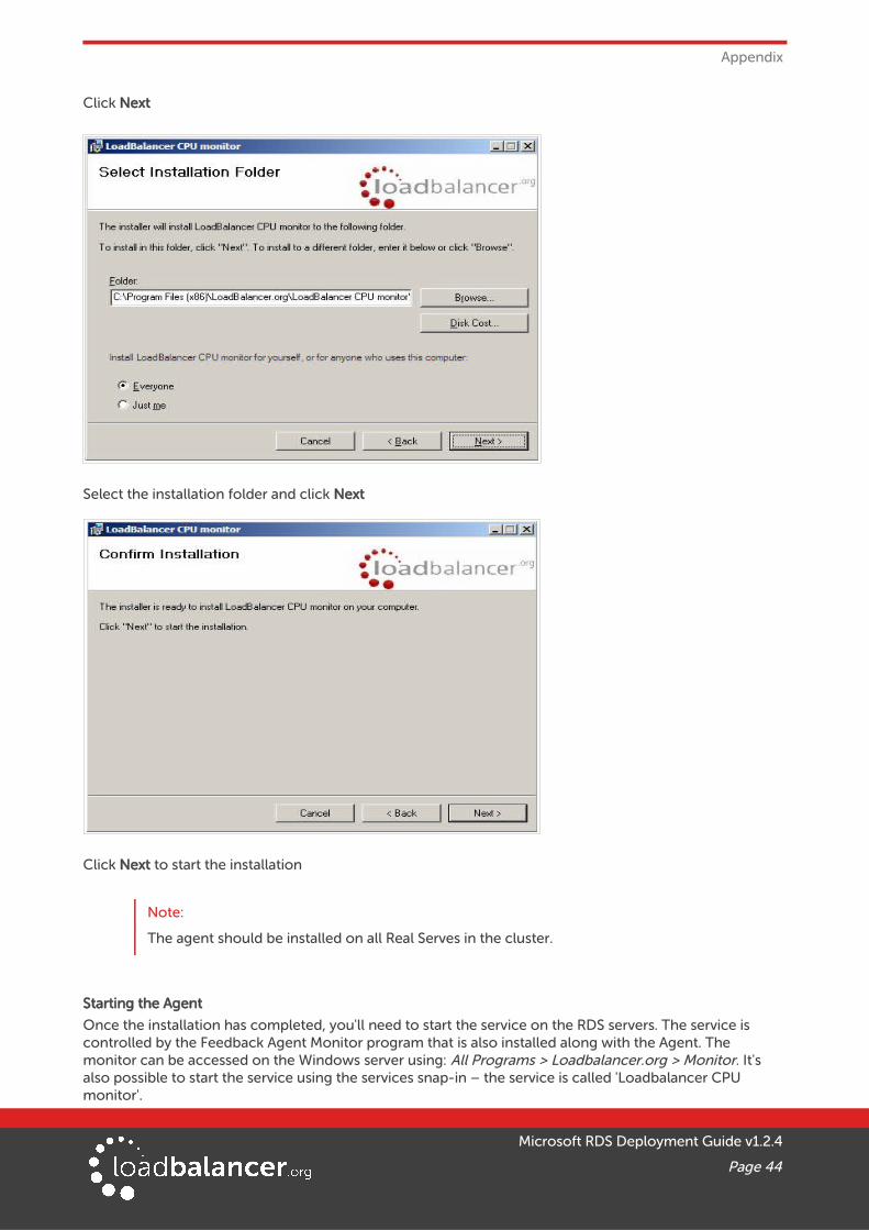
Click Next
Select the installation folder and click Next
Click Next to start the installation
Note:
The agent should be installed on all Real Serves in the cluster.
Starting the Agent
Once the installation has completed, you'll need to start the service on the RDS servers. The service is controlled by the Feedback Agent Monitor program that is also installed along with the Agent. The monitor can be accessed on the Windows server using: All Programs > Loadbalancer.org > Monitor. It's also possible to start the service using the services snap-in – the service is called 'Loadbalancer CPU monitor'.
Microsoft RDS Deployment Guide v1.2.4
Page 44

Appendix
• To start the service, click Start
• To stop the service, click Stop
Configuration
To Configure Virtual Services to use the feedback agent, follow the steps below:
1. Using the WebUI, navigate to: Cluster Configuration > Layer 4 - Virtual Services or Layer 7 - Virtual Services
2. Click Modify next to the Virtual Service
3. Change the Feedback Method to Agent
4. Click Update
5. For layer 7 VIPs, restart HAProxy using the WebUI option: Maintenance > Restart Services
4 - CONFIGURING WINDOWS 2008 R2 FOR ROUTING TOKEN REDIRECTION MODEInstall Connection Broker on the server designated to hold the Connection Broker role. Then on each RDSto be included in the cluster/Farm:
1. Open Remote Desktop Host Session Configuration
2. Right–click 'Member of farm in RD Connection Broker' and select Properties
3. Click Change Settings
4. Select Farm Member, enter the DNS name of the server running the Connection Broker role service and the name of the farm (all servers within the same farm require the same name to be specified) and click OK
5. Leave Participate in Connection Broker Load-Balancing un-checked and select Use token redirection from the drop down as shown below:
Microsoft RDS Deployment Guide v1.2.4
Page 45

Appendix
5 - CLUSTERED PAIR CONFIGURATION – ADDING A SLAVE UNITIf you initially configured just the master unit and now need to add a slave - our recommended procedure,please refer to the relevant section below for more details:
Note:
A number of settings are not replicated as part of the master/slave pairing process and thereforemust be manually configured on the slave appliance. These are listed below:
• Hostname & DNS settings
• Network settings including IP addresses, bonding configuration and VLANs
• Routing configuration including default gateways and static routes
• Date & time settings
• Physical – Advanced Configuration settings including Internet Proxy IP address & port, Firewall table size, SMTP relay and Syslog server
• SNMP settings
• Graphing settings
• Firewall Script & Firewall Lockdown Script settings
• Software updates
Version 7:
Please refer to Chapter 8 – Appliance Clustering for HA in the v7 Administration Manual.
Version 8:
To add a slave node – i.e. create a highly available clustered pair:
• Deploy a second appliance that will be the slave and configure initial network settings
• Using the WebUI, navigate to: Cluster Configuration > High-Availability Configuration
Microsoft RDS Deployment Guide v1.2.4
Page 46
Appendix
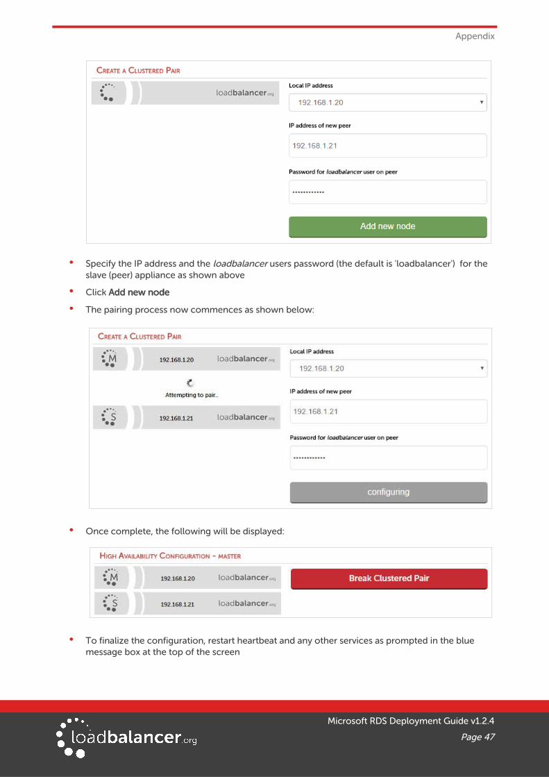
• Specify the IP address and the loadbalancer users password (the default is 'loadbalancer') for the slave (peer) appliance as shown above
• Click Add new node
• The pairing process now commences as shown below:
• Once complete, the following will be displayed:
• To finalize the configuration, restart heartbeat and any other services as prompted in the blue message box at the top of the screen
Microsoft RDS Deployment Guide v1.2.4
Page 47

Appendix
Note:
Clicking the Restart Heartbeat button on the master appliance will also automatically restart heartbeat on the slave appliance
Note:
Please refer to chapter 9 – Appliance Clustering for HA in the Administration Manual for more detailed information on configuring HA with 2 appliances.
Microsoft RDS Deployment Guide v1.2.4
Page 48

Appendix
6 - COMPANY CONTACT INFORMATION
Website URL: w w w.loadbalancer.org
North America (US) Loadbalancer.org, Inc.
4250 Lancaster Pike, Suite 120WilmingtonDE 19805USA
Tel:Fax:
Email (sales):Email (support):
+1 888.867.9504+1 [email protected]@loadbalancer.org
North America (Canada) Loadbalancer.org Ltd300-422 Richards StreetVancouver, BCV6B 2Z4Canada
Tel:Fax:
Email (sales):Email (support):
+1 866.998.0508+1 [email protected]@loadbalancer.org
Europe (UK) Loadbalancer.org Ltd.Compass HouseNorth Harbour Business ParkPortsmouth, PO6 4PSUK
Tel:Fax:
Email (sales):Email (support):
+44 (0)330 3801064+44 (0)870 [email protected]@loadbalancer.org
Europe (Germany) Loadbalancer.org GmbHTengstraße 27D-80798MünchenGermany
Tel:Fax:
Email (sales):Email (support):
+49 (0)89 2000 2179+49 (0)30 920 383 [email protected]@loadbalancer.org
Microsoft RDS Deployment Guide v1.2.4
Page 49