Embed Size (px)
Citation preview

1 of 13
PIPENET® Leading the Way in Fluid Flow Analysis
Application Bulletin PIPENET® LNG Applications
LNG Applications of PIPENET
PIPENET Software has 3 modules:
Transient Module
Spray/Sprinkler Module
Standard module
They all have applications in the design of LNG production, both in offshore platforms and in
LNG production/loading/regasification. Applications include the design of loading systems,
firewater systems and cooling water systems.
AAA. PIPENET Transient module:
1. LNG Loading System, Australia:
This is a system with 4 LNG pumps and 4 loading lines. This study considered the closure
of the ship (LNG tanker) valves and the simultaneous shutdown of all LNG pumps. Two of
the valves remained closed throughout. The other two valves closed simultaneously in 25
seconds (from 5 to 30). All 4 LNG pumps stopped in 10 seconds (from 5 to 15).
2 of 13
PIPENET® Leading the Way in Fluid Flow Analysis

3 of 13
PIPENET® Leading the Way in Fluid Flow Analysis
2. LNG Pump Startup:
This is an interesting scenario which considers pump start up with the piping system fully
primed. The pump starts and runs up during the time 5 – 15 seconds. The main valve
downstream of the pump starts during the time 5 – 65 seconds. Some of the valves in the
loading arms open during the time 5 – 15 seconds, while others remain closed.

4 of 13
PIPENET® Leading the Way in Fluid Flow Analysis
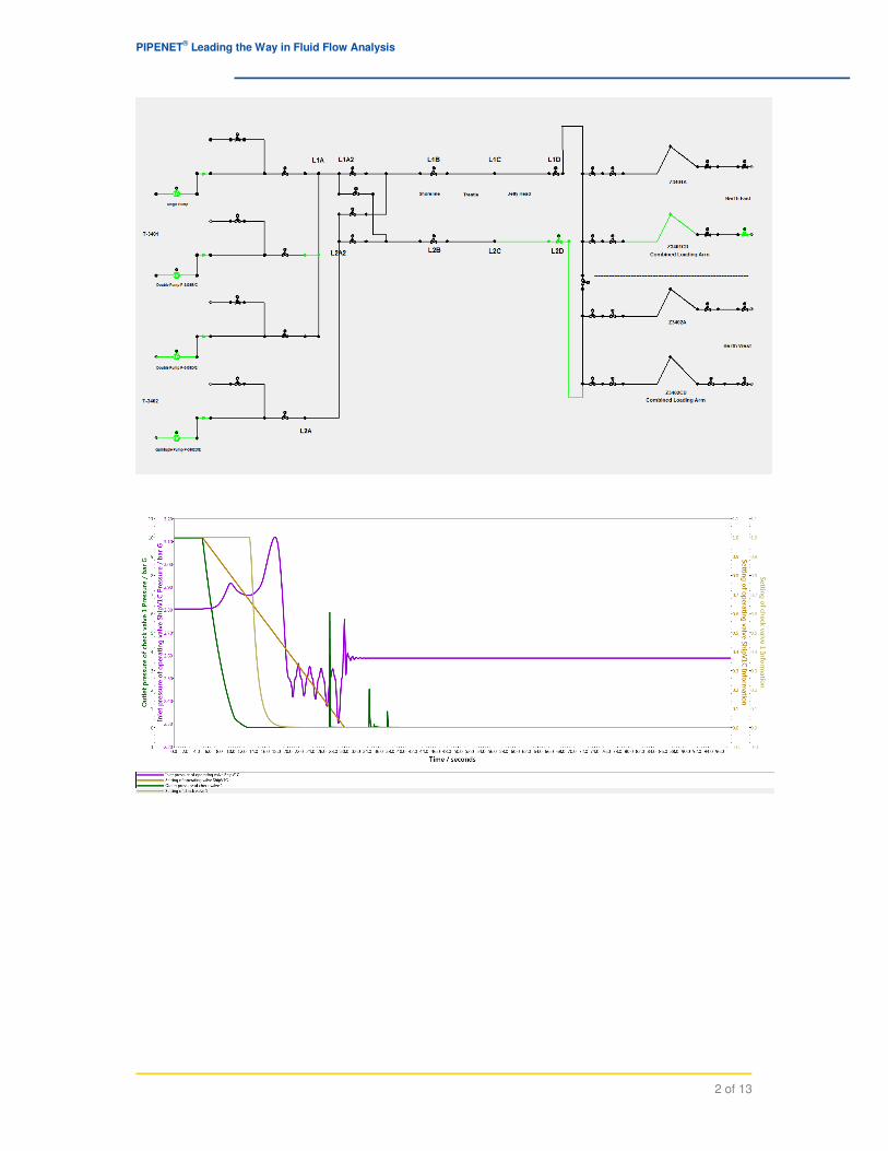
3. Yemen LNG Loading System:
The facility has two tanks with a total capacity of 280,000 m3. The jetty can handle 70,000
to 205,000 m3 of LNG capacity ships. The facility has 8 LNG pumps with a capacity of 1650
m3/hr each. The valves on the loading lines close in 5 seconds (from 5 to 10). The pumps
stop in 1 seconds (from 5 to 6). The bypass valves around the pump open in 10 seconds
(from 5 to 15)
5 of 13
PIPENET® Leading the Way in Fluid Flow Analysis
Typical graph:
6 of 13
PIPENET® Leading the Way in Fluid Flow Analysis
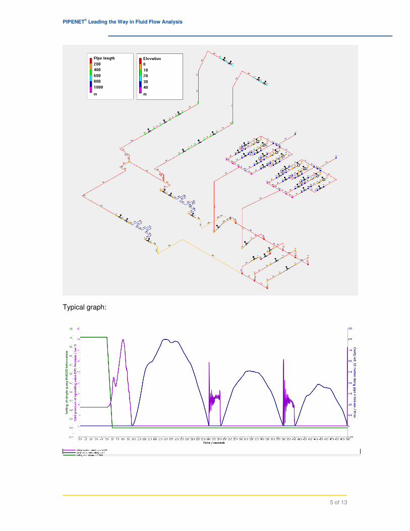
4. LNG Unloading System for Regasification:
The system had 7 lead pumps and 1 standby pump on the ship for unloading purposes. The
system has two surge relief valves. One unloading line is shut down. The valves in the
other line close in 5 seconds.

7 of 13
PIPENET® Leading the Way in Fluid Flow Analysis
5. LNG Loading System PERC Valve Closure:
In this LNG loading system the effect of the PERC (Powered Emergency Release Coupling)
valve closure is considered. The system has 12 LNG pumps and 6 PERC valves. Three of
the PERC valves close in 5 seconds and the other three remain open.

8 of 13
PIPENET® Leading the Way in Fluid Flow Analysis
6. LNG Plant Cooling Water System:
This shows the cooling water system on one of the largest facilities in the world. The system
has 7 variable speed lead pumps and 2 standby variable speed pumps. The design flowrate
of each pump is 42,840 m3/hr. The main manifold is 3.5 m diameter and is made of GRP
pipes. The minimum design pressure is -0.3 barg and the maximum is 6 barg. The system
had a number of PID controllers in order to regulate the speed of the pumps and position
flow control valves.
In this scenario the complete simultaneous shutdown of all the pumps due to power failure
was considered. In order to protect the pipes from collapsing 190 vacuum breakers were
installed.

9 of 13
PIPENET® Leading the Way in Fluid Flow Analysis
10 of 13
PIPENET® Leading the Way in Fluid Flow Analysis
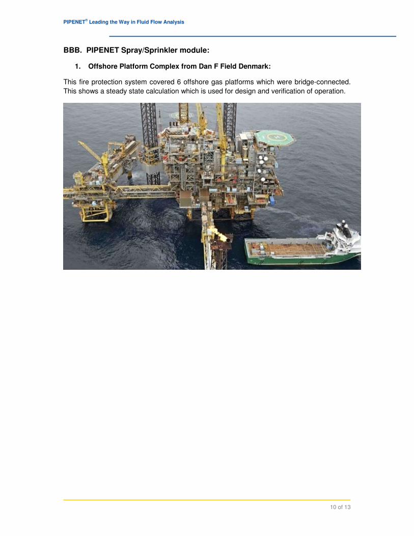
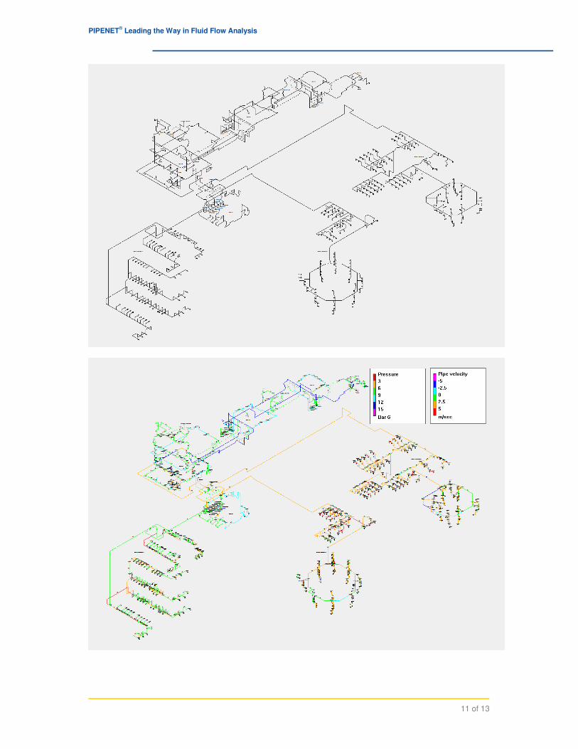
BBB. PIPENET Spray/Sprinkler module:
1. Offshore Platform Complex from Dan F Field Denmark:
This fire protection system covered 6 offshore gas platforms which were bridge-connected.
This shows a steady state calculation which is used for design and verification of operation.
11 of 13
PIPENET® Leading the Way in Fluid Flow Analysis

12 of 13
PIPENET® Leading the Way in Fluid Flow Analysis
2. Onshore Gas Processing Plant for Receiving Gas from Offshore Platform:
This shows the fire protection system on onshore gas reception facilities. The system had
two diesel pumps and 2 electric pumps.

Sunrise Systems Limited • Sunrise Business Park Ely Road • Waterbeach • Cambridge CB25 9QZ • United Kingdom Email: [email protected] • Web Site: www.sunrise-sys.com
13 of 13
PIPENET® Leading the Way in Fluid Flow Analysis
CCC. Standard Module :
LNG Plant Cooling Water System.
This is the steady state version of example 6 which was shown under PIPENET Transient
module applications. The purpose of this calculation was to select the pumps and size the
pipes.
If you have any questions about this case study, or any other of PIPENET’s capabilities,
please email us at [email protected].