Embed Size (px)
Citation preview

M. Ferre (Ed.): EuroHaptics 2008, LNCS 5024, pp. 151–156, 2008. © Springer-Verlag Berlin Heidelberg 2008
An Approach to Contact Force Vector Determination and Its Implementation to Provide Intelligent
Tactile Interaction with Environment
Dzmitry Tsetserukou, Naoki Kawakami, and Susumu Tachi
Department of Information Physics and Computing, University of Tokyo, 7-3-1 Hongo, Bunkyo-ku, Tokyo, 113-8656 Japan [email protected],
{kawakami, tachi}@star.t.u-tokyo.ac.jp
Abstract. The force vector information is essential while collision avoidance planning through tactile feedback in autonomous or teleoperation mode. In this paper, we concentrate on the approach to calculation of the applied force vector at any point of the robot arm and its technical realization. Based on the pre-sented force vector calculation flow, we obtained the experimental results vali-dating the ability of the proposed method to trace the contact point position and to estimate force vector robustly and accurately.
Keywords: Human-Robot interaction, sensitive robot arm.
1 Introduction
Recently, the new generation of robots called “service robots” has been advancing rapidly and it is considered that in near future they will be introduced in human daily life environment to assist with hospital care, surgery operations, high-risk mainte-nance tasks, construction works, and office affairs. Along with voice and image recognition, the robot tactile ability becomes salient link in the chain of multimodal interaction with humans. Moreover, the robot sensor system enabling detection of the mechanical contact with object in unstructured dynamic environment is needed, be-cause the occlusion in video and proximity sensor system can happen.
Conventional approaches to controlling the physical interaction between a manipu-lator and environment are based on impedance control of a robot arm according to applied force vector measured at the manipulator wrist [1]. However, the rest parts of the robot body (forearm, elbow, upper arm, shoulder, and torso) are presenting the significant danger not only for human being, but also for the robot structure itself. The ability to sense the physical contact can be attained by covering the robot surface with tactile skin [2].
With tactile sensing technology continuously evolving, different types of tactile sensors such as piezoelectric-polymer-film-based [2], flexible-polyester-sheet-based, optical [3], etc. have been designed. Such sensors can only detect the contact area and coarsely measure the spatial distribution of pressures perpendicular to a sensory area. Therefore, they are unable to supply contact force orientation information. The most
152 D. Tsetserukou, N. Kawakami, and S. Tachi
appropriate application of such tactile sensors is recognition of contact area gravity center and contact image pattern.
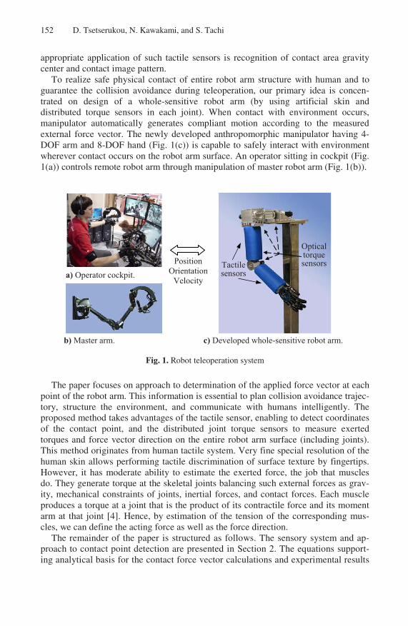
To realize safe physical contact of entire robot arm structure with human and to guarantee the collision avoidance during teleoperation, our primary idea is concen-trated on design of a whole-sensitive robot arm (by using artificial skin and distributed torque sensors in each joint). When contact with environment occurs, manipulator automatically generates compliant motion according to the measured external force vector. The newly developed anthropomorphic manipulator having 4-DOF arm and 8-DOF hand (Fig. 1(c)) is capable to safely interact with environment wherever contact occurs on the robot arm surface. An operator sitting in cockpit (Fig. 1(a)) controls remote robot arm through manipulation of master robot arm (Fig. 1(b)).
a) Operator cockpit.
b) Master arm.
PositionOrientation
Velocity
Tactile sensors
Optical torquesensors
c) Developed whole-sensitive robot arm.
Fig. 1. Robot teleoperation system
The paper focuses on approach to determination of the applied force vector at each point of the robot arm. This information is essential to plan collision avoidance trajec-tory, structure the environment, and communicate with humans intelligently. The proposed method takes advantages of the tactile sensor, enabling to detect coordinates of the contact point, and the distributed joint torque sensors to measure exerted torques and force vector direction on the entire robot arm surface (including joints). This method originates from human tactile system. Very fine special resolution of the human skin allows performing tactile discrimination of surface texture by fingertips. However, it has moderate ability to estimate the exerted force, the job that muscles do. They generate torque at the skeletal joints balancing such external forces as grav-ity, mechanical constraints of joints, inertial forces, and contact forces. Each muscle produces a torque at a joint that is the product of its contractile force and its moment arm at that joint [4]. Hence, by estimation of the tension of the corresponding mus-cles, we can define the acting force as well as the force direction.
The remainder of the paper is structured as follows. The sensory system and ap-proach to contact point detection are presented in Section 2. The equations support-ing analytical basis for the contact force vector calculations and experimental results

An Approach to Contact Force Vector Determination 153
are given in Section 3. In Section 4, we briefly conclude the paper and discuss the future work.
2 Sensory System of the Developed Robot Arm
The robot arm is covered with Kinotex tactile sensor measuring the pressure intensity through amount of backscattered light by photodetector [5]. The sensitivity, resolu-tion, and dynamic range of this artificial skin are comparable to those of a human. The taxels displaced with 21.5 mm in X and 22 mm in Y direction make up 6x10 array.
In order to recognize the contact region, we employed the watershed algorithm, an image processing segmentation technique that splits an image into areas based on the topology of the image [6]. The adopted algorithm is processed as follows: departing from the local maximum, the new taxel is included into the contact area only if within the 3x3 array surrounding it there is an other taxel of greater or equal pressure inten-sity already included into the water stream.
The accurate estimation of the contact point can be obtained by computing the cen-ter of gravity of the contact pattern c(xc,yc) of the neighborhood Ω by:
( )( )
( )
( )
( ), ,
, ,
, ,
, ,, ,
i i i i i i i ix y x y
c ci i i i i i
x y x y
x f x y y f x y
c x yf x y f x y
∈Ω ∈Ω
∈Ω ∈Ω
⎛ ⎞⎜ ⎟= ⎜ ⎟⎜ ⎟⎝ ⎠
∑ ∑∑ ∑
, (1)
where fi(xi,yi) is the pressure intensity level of the taxel i with coordinates (xi,yi) [7]. Calculation findings of image gravity center are listed in Table 1.
Table 1. Calculation results of image gravity center
Y,mm
Pressure intensity fi,j
xi,jfi,j yi,jfi,j xc yc
157 0 114 190
482985 607541 94.4 118.8 135 26 1303 755
113 56 859 463
91 553 796 0
X,mm 43 75 106 Digital image Visual image
yc
xc
In order to facilitate the realization of torque measurement in each arm joint, we developed new optical torque sensors having high reliability, high accuracy (even in electrically noisy environment), easy mounting procedure, low price and compact sizes [8]. The novelty of our method is application of the ultra-small size photointer-rupter (PI) RPI-121 as sensitive element to measure relative motion of sensor compo-nents. The spring components were manufactured from one piece of AISI 4135 steel using wire electrical discharge machining. The optical torque sensor is set between
154 D. Tsetserukou, N. Kawakami, and S. Tachi
X
4
Z5
Z
X34
Y5
Z3F4L
4YY3
J4
J3
Z
Z
J2
2Y
2
2
X
LF2
J1
+
Pitch
YX
Roll
+0
Yaw+
0
0
1Z
Y1 X1
2x
z 22y
F2
y
x4
F44
z 4
X5
L2
4L
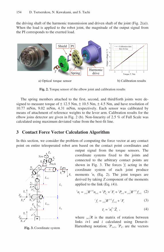
the driving shaft of the harmonic transmission and driven shaft of the joint (Fig. 2(a)). When the load is applied to the robot joint, the magnitude of the output signal from the PI corresponds to the exerted load.
SpringHarmonic
drive1
PI
2
T
Shield
-4 -2 0 2 42
3
4
5
6
7
8
Calibration data Best fit line
Out
put v
olta
ge U
, V
Torque T, Nm
a) Optical torque sensor b) Calibration results
Fig. 2. Torque sensor of the elbow joint and calibration results
The spring members attached to the first, second, and third/forth joints were de-signed to measure torque of ± 12.5 Nm, ± 10.5 Nm, ± 4.5 Nm, and have resolution of 10.77 mNm, 9.02 mNm, 4.31 mNm, respectively. Each sensor was calibrated by means of attachment of reference weights to the lever arm. Calibration results for the elbow joins detector are given in Fig. 2 (b). Non-linearity of 2.5 % of Full Scale was calculated using maximum deviated value from the best-fit line.
3 Contact Force Vector Calculation Algorithm
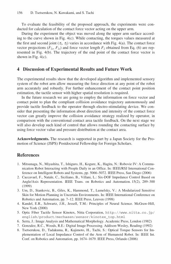
In this section, we consider the problem of computing the force vector at any contact point on entire teleoperated robot arm based on the contact point coordinates and
output signal from the torque sensors. The coordinate systems fixed to the joints and connected to the arbitrary contact points are shown in Fig. 3. The forces ifi acting in the coordinate system of each joint produce moments ini (Eq. 2). The joint torques are derived by taking Z component of the moments applied to the link (Eq. (4)).
1 11 1 1 1 1i
i i i i i i i ii i i C i i i in R n P F P R f+ +
+ + + + += + × + × (2)
11 1
i i i ii i i if R f F+
+ += + (3)
ˆi T ii i in Zτ = , (4)
where i+1iR is the matrix of rotation between
links i+1 and i calculated using Denavit-Hartenberg notation; iPi+1,
iPCi are the vectors Fig. 3. Coordinate system

An Approach to Contact Force Vector Determination 155
locating the origin of the coordinate system i+1 in the system i, and contact point, respectively; iFi is the contact force.
Let us consider the case when external force is applied to the upper arm of the ro-bot. Using the Eq. (2), (3) we have:
2 2 2 2 2 2 2 2 2 22 1
2 2 2 1 2 2
2 2 2 2 2 2 2 2 2 2
0 0
0 ; 0 0 1 0
0 0
x F z F z F z
F y F x
z F x F x F z
F L F s c L F L F s
n L F n L F
F L F c s L F L F c
⎡ ⎤ ⎡ ⎤ ⎡ ⎤ ⎡ ⎤ ⎡ ⎤ ⎡ ⎤⎢ ⎥ ⎢ ⎥ ⎢ ⎥ ⎢ ⎥ ⎢ ⎥ ⎢ ⎥= × = = = −⎢ ⎥ ⎢ ⎥ ⎢ ⎥ ⎢ ⎥ ⎢ ⎥ ⎢ ⎥⎢ ⎥ ⎢ ⎥ ⎢ ⎥ ⎢ ⎥ ⎢ ⎥ ⎢ ⎥− − −⎣ ⎦ ⎣ ⎦ ⎣ ⎦ ⎣ ⎦ ⎣ ⎦ ⎣ ⎦
. (5)
The components of the applied force vector and force magnitude are derived from:
( ) ( ) ( ) ( )2 2
2 2 2 2 1 2 2 2 2 2 ; ; x F z F x zF L F L c F F Fτ τ= − = = + . (6)
The value of the applied force projection on the axis Y is not required because the upper arm cannot move in this direction. For the case when the force acts on the fore-arm we have the following algorithm to obtain the contact force vector:
( )4 4 4 4 3 4 4 ; x F z FF L F L sτ τ= = ;
( ) ( )4 2 4 4 3 4 2 3 4 4 3 2 3 4 2 3 4( ) ( )y z F x FF F L c c L c F L s L s c L s sτ= + + + + , (7)
where c2, c3, c4, s3, and s4 are abbreviations for cos(θ2), cos(θ3), cos(θ4), sin(θ3), and sin(θ4), respectively; L2, LF2, and LF4 are the lengths of the moment arms.
0 4 8 12 16-12
-8
-4
0
4
8
12
Time t, sec
Con
tact
for
ce c
ompo
nent
s F
2, N
F2
F2z
F2x
120 140 160 180 200 22080
100
120
140
160
180
200
Con
tact
poi
nt lo
catio
n y,
mm
Contact point location x, mm
-12 -10 -8 -6 -4 -2 0-8
-6
-4
-2
0
2
4
6
8
Con
tact
for
ce c
ompo
nent
s F
z2 ,
N
Contact force components Fx2
, N
0 4 8 12 16
-1.5
-1.0
-0.5
0.0
0.5
1.0
1.5
2.0
Applied torque Applied torque A
pplie
d to
rque
E
XT, N
m
Time t, seca) c)
b) d)
Fig. 4. Torque sensor of the elbow joint and elbow joint assembly
156 D. Tsetserukou, N. Kawakami, and S. Tachi
To evaluate the feasibility of the proposed approach, the experiments were con-ducted for calculation of the contact force vector acting on the upper arm.
During the experiment the object was moved along the upper arm surface accord-ing to the curve shown in Fig. 4(c). While contacting, the torques values measured at the first and second joint (τ1, τ2) varies in accordance with Fig. 4(a). The contact force vector projections (F2x, F2z) and force vector length F2 obtained from Eq. (6) are rep-resented in Fig. 4(b). The trajectory of the end point of the contact force vector is shown in Fig. 4(c).
4 Discussion of Experimental Results and Future Work
The experimental results show that the developed algorithm and implemented sensory system of the robot arm allow measuring the force direction at any point of the robot arm accurately and robustly. For further enhancement of the contact point position estimation, the tactile sensor with higher spatial resolution is required.
In the future research we are going to employ the information on force vector and contact point to plan the compliant collision avoidance trajectory autonomously and provide tactile feedback to the operator through electro-stimulating device. We con-sider that presenting the information about direction and intensity of the contact force vector can greatly improve the collision avoidance strategy realized by operator, in comparison with the conventional contact area tactile feedback. On the next stage we will also develop such kind of control that allows rounding the contacting surface by using force vector value and pressure distribution at the contact area.
Acknowledgments. The research is supported in part by a Japan Society for the Pro-motion of Science (JSPS) Postdoctoral Fellowship for Foreign Scholars.
References
1. Mitsunaga, N., Miyashita, T., Ishiguro, H., Kogure, K., Hagita, N.: Robovie IV: A Commu-nication Robot Interacting with People Daily in an Office. In: IEEE/RSJ International Con-ference on Intelligent Robots and Systems, pp. 5066–5072. IEEE Press, San Diego (2006)
2. Caccavael, F., Natale, C., Siciliano, B., Villani, L.: Six-DOF Impedance Control Based on Angle/Axis Representation. IEEE Trans. on Robotics and Automation. 15(2), 289–300 (1999)
3. Um, D., Stankovic, B., Giles, K., Hammond, T., Lumelsky, V.: A Modularized Sensitive Skin for Motion Planning in Uncertain Environments. In: IEEE International Conference on Robotics and Automation, pp. 7–12. IEEE Press, Leuven (1998)
4. Kandel, E.R., Schwartz, J.H., Jessell, T.M.: Principles of Neural Science. McGraw-Hill, New York (2000)
5. Optic Fiber Tactile Sensor Kinotex, Nitta Corporation, http://www.nitta.co.jp/ english/product/mechasen/sensor/kinotex_top.html
6. Serra, J.: Image Analysis and Mathematical Morphology. Academic Press, London (1982) 7. Gonzalez, R.C., Woods, R.E.: Digital Image Processing. Addison-Wesley, Reading (1992) 8. Tsetserukou, D., Tadakuma, R., Kajimoto, H., Tachi, S.: Optical Torque Sensors for Im-
plementation of Local Impedance Control of the Arm of Humanoid Robot. In: IEEE Int. Conf. on Robotics and Automation, pp. 1674–1679. IEEE Press, Orlando (2006)