Embed Size (px)
Citation preview

User's GuideSNVA426B–January 2010–Revised April 2013
AN-2030 LMZ10503 / LMZ10504 Demo Board SIMPLESWITCHER® Power Module Quick Start Guide
1 Introduction
The LMZ10503/4 SIMPLE SWITCHER power module is a complete, easy-to-use DC-DC solution capableof driving up to a 4A load with exceptional power conversion efficiency, output voltage accuracy, line andload regulation. The LMZ10503/4 is available in an innovative package that enhances thermalperformance and allows for hand or machine soldering.
The LMZ10503/4 can accept an input voltage rail between 2.95V and 5.5V and deliver an adjustable andhighly accurate output voltage as low as 0.8V. One megahertz fixed frequency PWM switching provides apredictable EMI characteristic. Two external compensation components can be adjusted to set the fastestresponse time, while allowing the option to use ceramic and/or electrolytic output capacitors. Externallyprogrammable soft-start capacitor facilitates controlled startup. The LMZ10503/4 is a reliable and robustsolution with the following features: lossless cycle-by-cycle peak current limit to protect for over current orshort-circuit fault, thermal shutdown, input under-voltage lock-out, and pre-biased startup.
2 Packaging Highlights• Single exposed pad and standard pin out for easy mounting and manufacturing
• 10.2 x 13.8 x 4.6 mm (0.4 x 0.39 x 0.18 in) package
• 20W maximum total output power
• 1.7” x 2.3” (4.3 cm x 5.8 cm) reduced size demo board form factor
3 Demo Board Features• Power input voltage range 2.95V-5.5V
• Input UVLO at 2.7V
• Adjustable output voltage range 0.8V to 5V
• Up to 4A output current (LMZ10504)
• Up to 3A output current (LMZ10503)
• Integrated shielded inductor in module
• Efficiency up to 96% at 1A load
• All ceramic capacitor design
• Partial compensation allows adjustment of the control loop
• Starts into pre-biased loads
• ±1.63% maximum feedback voltage accuracy over temperature
• ±2.5% maximum feedback voltage accuracy over full line, load, and temperature conditions
• Thermal Shutdown
• Only 9 external passives plus module
• Two layer low cost assembly
SIMPLE SWITCHER is a registered trademark of Texas Instruments.All other trademarks are the property of their respective owners.
1SNVA426B–January 2010–Revised April 2013 AN-2030 LMZ10503 / LMZ10504 Demo Board SIMPLE SWITCHER® PowerModule Quick Start GuideSubmit Documentation Feedback
Copyright © 2010–2013, Texas Instruments Incorporated

Typical Applications www.ti.com
4 Typical Applications• Point-of-load conversions from 3.3V and 5V rails
• Space constrained applications
• Extreme temperatures/no air flow environments
• Noise sensitive applications (i.e. transceiver, medical)
• Industrial controls
• Networking equipment
Figure 1. Top Layer
Figure 2. Bottom Layer
Table 1. Absolute Maximum Module Ratings
VIN to GND -0.3V to 6V
EN, FB, SS to GND -0.3V to 6V
2 AN-2030 LMZ10503 / LMZ10504 Demo Board SIMPLE SWITCHER® Power SNVA426B–January 2010–Revised April 2013Module Quick Start Guide Submit Documentation Feedback
Copyright © 2010–2013, Texas Instruments Incorporated

www.ti.com Demo Board Schematic
Table 2. Module Operating Ratings
VIN 2.95V to 5.5V
Junction Temperature Range (TJ) -40°C to +125°C
Table 3. Demo Board Operating Ratings
VIN 2.95V to 5.5V
VOUT 2.5V
IOUT 0A to 4A or 0A to 3A
Softstart time 4 ms
Operating Ambient Temperature Range (TA) - 40°C to +94°C (at full 4A load)
θJA 30°C/W
θJC 1.9°C/W
Board Dimensions 1.7 x 2.3 (4.3 cm x 5.8 cm)
Number of Layers 2
5 Demo Board Schematic
Table 4. Demo Board Bill of Materials
Ref Des Description Case Size Manufacturer Manufacturer P/N Quantity
U1 SIMPLE SWITCHER TO-PMOD Texas Instruments LMZ10503/4 1
Cin1, Co1, Co2 47 µF, X5R, 16V 1206 TDK C3216X5R1C476M 3
Cin2 220 µF, 10V, AL-Elec E Panasonic EEE-FPA221XAP 0 (1)
120 pF, 5%, C0G,Ccomp 50V 0603 TDK C1608C0G1H121J 1
Css 10 nF, 5%, C0G, 25V 0603 TDK C1608C0G1E103J 1
Rfbt 75 kΩ 0603 Vishay Dale CRCW060375K0FKEA 1
Rfbb 34.8 kΩ 0603 Vishay Dale CRCW060334K8FKEA 1
Rcomp 1.1 kΩ 0603 Vishay Dale CRCW06031K10FKEA 1
Ren 100 kΩ 0603 Vishay Dale CRCW0603100KFKEA 1
VIN, GND, VOUT Turret Terminal 1502-2 Keystone 1502-2K-ND 4
EN, SS Turret Terminal 1593-2 Keystone 1593-2K-ND 2(1) Not installed
3SNVA426B–January 2010–Revised April 2013 AN-2030 LMZ10503 / LMZ10504 Demo Board SIMPLE SWITCHER® PowerModule Quick Start GuideSubmit Documentation Feedback
Copyright © 2010–2013, Texas Instruments Incorporated

Demo Board Hookup www.ti.com
Table 5. Output Voltage Setting (Rfbt = 75 kΩ)
VOUT Rfbb
3.3 V 23.7 kΩ2.5 V 34.8 kΩ1.8 V 59 kΩ1.5 V 84.5 kΩ1.2 V 150 kΩ0.9 V 590 kΩ
6 Demo Board Hookup
VOUT Connect the load to VOUT and one of the GND posts. The module can source up to a 3A or 4Aload current, depending on the module installed.
VIN Connect VIN to a positive voltage in the 2.95 to 5.5V range. Connect the negative terminal of thesource supply to one of the posts labeled GND.
EN The enable is configured with a 100 kΩ pull up resistor, which enables the LMZ10503/4, but alsoallows the user to disable the LMZ10503/4, by pulling low on the EN post.
Quiescent current If the enable post is pulled low, the module will be disabled and about 260 µA ofsupply current will flow into VIN (pin 1). To enable the device, leave the enable post open, there will beapproximately 12 mA of no-load quiescent current into the VIN post. (VIN to ground voltage at the post setto 3.3V).
7 Demo Board Passive Components
Soft-start capacitor The soft-start capacitor controls the rise time of the output voltage when power isfirst applied and following the clearing of a fault mode.
Feedback divider Regulator output voltage is programmed though the selection of the two resistors, Rfbb
and Rfbt. Ccomp Rcomp is located in parallel with the upper feedback divider resistor, Rfbt. These componentsadjust the control loop and will improve the step response to abrupt changes in load current and inputvoltage.
Output Capacitor Parallel connections of two 47 µF 6.3V multilayer ceramic are used for the outputcapacitor.
Input Capacitor A 47 µF 16V multilayer ceramic (Cin1) supplies the fast switching current generated fromthe quick rise time of the internal MOSFET. Cin1 is also the energy reservoir for the input line. Additionally,Cin2 is not installed, but is a placeholder for an aluminum capacitor to reduce the resonance of the inputline produced by the inductance and resistance in the cables connecting the bench power supply to theevaluation board and the input capacitors.
8 Performance Characteristics
The following curves apply to the LMZ10504 demo board.
4 AN-2030 LMZ10503 / LMZ10504 Demo Board SIMPLE SWITCHER® Power SNVA426B–January 2010–Revised April 2013Module Quick Start Guide Submit Documentation Feedback
Copyright © 2010–2013, Texas Instruments Incorporated
www.ti.com Performance Characteristics
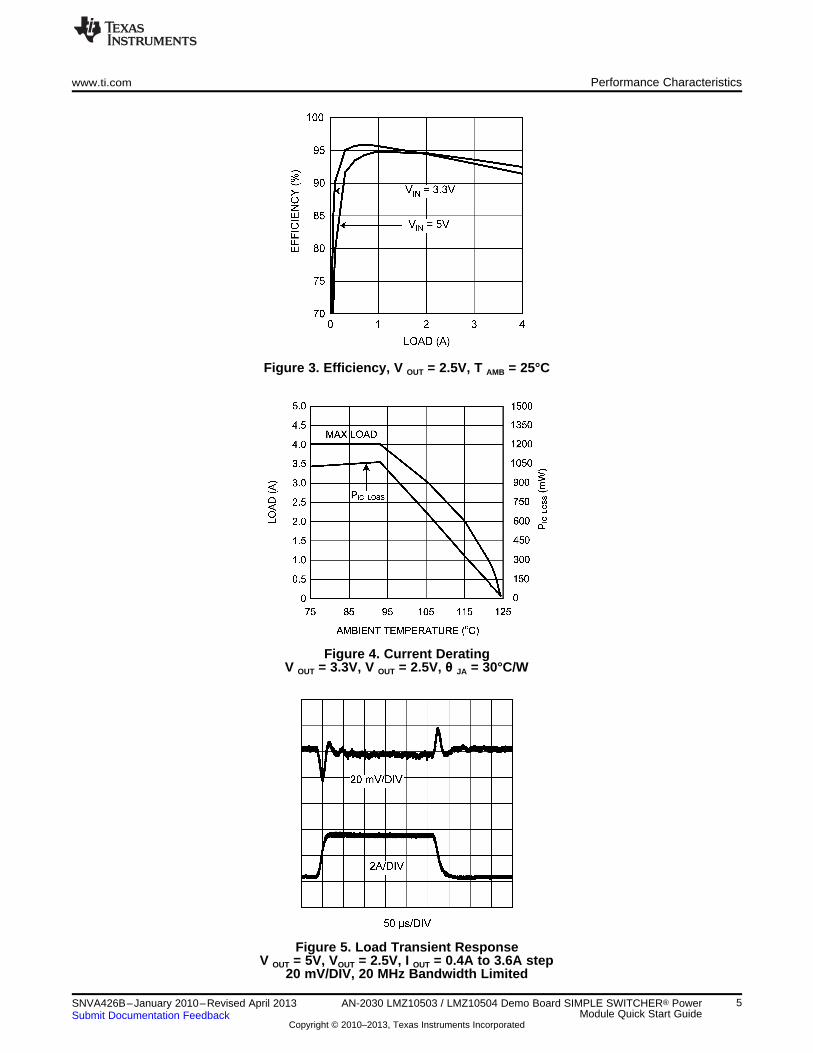
Figure 3. Efficiency, V OUT = 2.5V, T AMB = 25°C
Figure 4. Current DeratingV OUT = 3.3V, V OUT = 2.5V, θ JA = 30°C/W
Figure 5. Load Transient ResponseV OUT = 5V, VOUT = 2.5V, I OUT = 0.4A to 3.6A step
20 mV/DIV, 20 MHz Bandwidth Limited
5SNVA426B–January 2010–Revised April 2013 AN-2030 LMZ10503 / LMZ10504 Demo Board SIMPLE SWITCHER® PowerModule Quick Start GuideSubmit Documentation Feedback
Copyright © 2010–2013, Texas Instruments Incorporated
Performance Characteristics www.ti.com
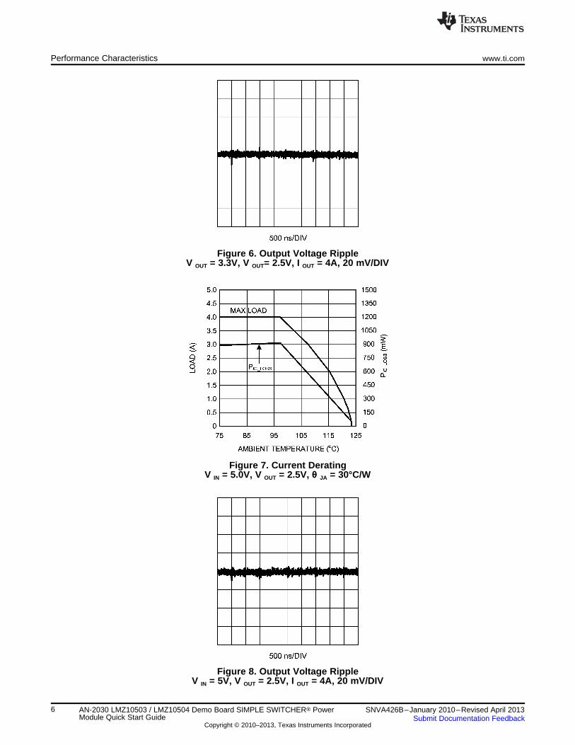
Figure 6. Output Voltage RippleV OUT = 3.3V, V OUT= 2.5V, I OUT = 4A, 20 mV/DIV
Figure 7. Current DeratingV IN = 5.0V, V OUT = 2.5V, θ JA = 30°C/W
Figure 8. Output Voltage RippleV IN = 5V, V OUT = 2.5V, I OUT = 4A, 20 mV/DIV
6 AN-2030 LMZ10503 / LMZ10504 Demo Board SIMPLE SWITCHER® Power SNVA426B–January 2010–Revised April 2013Module Quick Start Guide Submit Documentation Feedback
Copyright © 2010–2013, Texas Instruments Incorporated

www.ti.com Performance Characteristics
Figure 9. Load Transient ResponseV IN = 3.3V, V OUT= 2.5V , I OUT = 0.4A to 3.6A step
20 mV/DIV, 20 MHz Bandwidth Limited
7SNVA426B–January 2010–Revised April 2013 AN-2030 LMZ10503 / LMZ10504 Demo Board SIMPLE SWITCHER® PowerModule Quick Start GuideSubmit Documentation Feedback
Copyright © 2010–2013, Texas Instruments Incorporated

IMPORTANT NOTICE
Texas Instruments Incorporated and its subsidiaries (TI) reserve the right to make corrections, enhancements, improvements and otherchanges to its semiconductor products and services per JESD46, latest issue, and to discontinue any product or service per JESD48, latestissue. Buyers should obtain the latest relevant information before placing orders and should verify that such information is current andcomplete. All semiconductor products (also referred to herein as “components”) are sold subject to TI’s terms and conditions of salesupplied at the time of order acknowledgment.
TI warrants performance of its components to the specifications applicable at the time of sale, in accordance with the warranty in TI’s termsand conditions of sale of semiconductor products. Testing and other quality control techniques are used to the extent TI deems necessaryto support this warranty. Except where mandated by applicable law, testing of all parameters of each component is not necessarilyperformed.
TI assumes no liability for applications assistance or the design of Buyers’ products. Buyers are responsible for their products andapplications using TI components. To minimize the risks associated with Buyers’ products and applications, Buyers should provideadequate design and operating safeguards.
TI does not warrant or represent that any license, either express or implied, is granted under any patent right, copyright, mask work right, orother intellectual property right relating to any combination, machine, or process in which TI components or services are used. Informationpublished by TI regarding third-party products or services does not constitute a license to use such products or services or a warranty orendorsement thereof. Use of such information may require a license from a third party under the patents or other intellectual property of thethird party, or a license from TI under the patents or other intellectual property of TI.
Reproduction of significant portions of TI information in TI data books or data sheets is permissible only if reproduction is without alterationand is accompanied by all associated warranties, conditions, limitations, and notices. TI is not responsible or liable for such altereddocumentation. Information of third parties may be subject to additional restrictions.
Resale of TI components or services with statements different from or beyond the parameters stated by TI for that component or servicevoids all express and any implied warranties for the associated TI component or service and is an unfair and deceptive business practice.TI is not responsible or liable for any such statements.
Buyer acknowledges and agrees that it is solely responsible for compliance with all legal, regulatory and safety-related requirementsconcerning its products, and any use of TI components in its applications, notwithstanding any applications-related information or supportthat may be provided by TI. Buyer represents and agrees that it has all the necessary expertise to create and implement safeguards whichanticipate dangerous consequences of failures, monitor failures and their consequences, lessen the likelihood of failures that might causeharm and take appropriate remedial actions. Buyer will fully indemnify TI and its representatives against any damages arising out of the useof any TI components in safety-critical applications.
In some cases, TI components may be promoted specifically to facilitate safety-related applications. With such components, TI’s goal is tohelp enable customers to design and create their own end-product solutions that meet applicable functional safety standards andrequirements. Nonetheless, such components are subject to these terms.
No TI components are authorized for use in FDA Class III (or similar life-critical medical equipment) unless authorized officers of the partieshave executed a special agreement specifically governing such use.
Only those TI components which TI has specifically designated as military grade or “enhanced plastic” are designed and intended for use inmilitary/aerospace applications or environments. Buyer acknowledges and agrees that any military or aerospace use of TI componentswhich have not been so designated is solely at the Buyer's risk, and that Buyer is solely responsible for compliance with all legal andregulatory requirements in connection with such use.
TI has specifically designated certain components as meeting ISO/TS16949 requirements, mainly for automotive use. In any case of use ofnon-designated products, TI will not be responsible for any failure to meet ISO/TS16949.
Products Applications
Audio www.ti.com/audio Automotive and Transportation www.ti.com/automotive
Amplifiers amplifier.ti.com Communications and Telecom www.ti.com/communications
Data Converters dataconverter.ti.com Computers and Peripherals www.ti.com/computers
DLP® Products www.dlp.com Consumer Electronics www.ti.com/consumer-apps
DSP dsp.ti.com Energy and Lighting www.ti.com/energy
Clocks and Timers www.ti.com/clocks Industrial www.ti.com/industrial
Interface interface.ti.com Medical www.ti.com/medical
Logic logic.ti.com Security www.ti.com/security
Power Mgmt power.ti.com Space, Avionics and Defense www.ti.com/space-avionics-defense
Microcontrollers microcontroller.ti.com Video and Imaging www.ti.com/video
RFID www.ti-rfid.com
OMAP Applications Processors www.ti.com/omap TI E2E Community e2e.ti.com
Wireless Connectivity www.ti.com/wirelessconnectivity
Mailing Address: Texas Instruments, Post Office Box 655303, Dallas, Texas 75265Copyright © 2013, Texas Instruments Incorporated