Embed Size (px)
Citation preview

Little DevilLittle DevilLittle DevilLittle Devil

© 2011 by Shattered Glass Audio. 2
© 2011 by Shattered Glass Audio.
All rights reserved. No part of this document may be reproduced or transmitted in any
form or by any means, electronic, mechanical, photocopying, recording, or otherwise,
without prior written permission of Shattered Glass Audio.
© 2011 by Shattered Glass Audio. 3
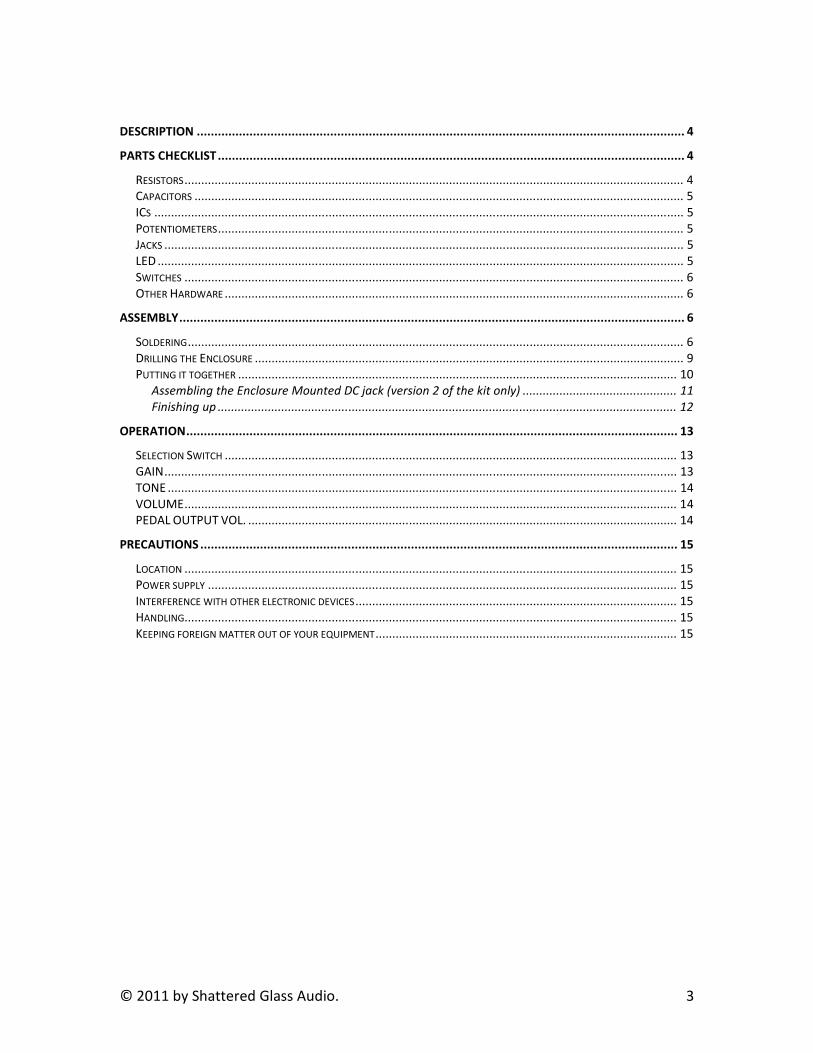
DESCRIPTION ........................................................................................................................................... 4
PARTS CHECKLIST..................................................................................................................................... 4
RESISTORS..................................................................................................................................................... 4
CAPACITORS .................................................................................................................................................. 5
ICS .............................................................................................................................................................. 5
POTENTIOMETERS........................................................................................................................................... 5
JACKS ........................................................................................................................................................... 5
LED ............................................................................................................................................................. 5
SWITCHES ..................................................................................................................................................... 6
OTHER HARDWARE ......................................................................................................................................... 6
ASSEMBLY................................................................................................................................................ 6
SOLDERING.................................................................................................................................................... 6
DRILLING THE ENCLOSURE ................................................................................................................................ 9
PUTTING IT TOGETHER ................................................................................................................................... 10
Assembling the Enclosure Mounted DC jack (version 2 of the kit only) .............................................. 11
Finishing up ......................................................................................................................................... 12
OPERATION............................................................................................................................................ 13
SELECTION SWITCH ....................................................................................................................................... 13
GAIN......................................................................................................................................................... 13
TONE ........................................................................................................................................................ 14
VOLUME................................................................................................................................................... 14
PEDAL OUTPUT VOL. ................................................................................................................................ 14
PRECAUTIONS ........................................................................................................................................ 15
LOCATION ................................................................................................................................................... 15
POWER SUPPLY ............................................................................................................................................ 15
INTERFERENCE WITH OTHER ELECTRONIC DEVICES................................................................................................ 15
HANDLING................................................................................................................................................... 15
KEEPING FOREIGN MATTER OUT OF YOUR EQUIPMENT.......................................................................................... 15
© 2011 by Shattered Glass Audio. 4
Description The Little Devil has no equal among portable, DC powered, small amps. It features full
pre and power amp sections. A wide range tone control lets you dial in the tone you
want. With its chimey cleans, two distinct flavors (smooth and gritty) of fat, growly,
overdrive, and a raunchy distortion when cranked up, the Little Devil is suitable for a
wide range of genres. By simply turning the switch, the Little Devil becomes an effects
pedal letting you take the sound you love to higher power levels. Connect the Little
Devil to your favorite speakers or amp and experience the sonic richness that Little Devil
has to offer.
Connectors:
INPUT Jack, OUTPUT Jack, AC Adaptor Jack (DC 9V)
Power Supply:
DC 9V: Dry Battery 9V type or a 9V, regulated, AC Adaptor
Controls:
GAIN, TONE, VOLUME, PEDAL OUTPUT VOL., OFF-AMP-PEDAL switch
Amp output:
~0.75W into 8Ω load. Amp can drive speakers from 4Ω -16Ω.
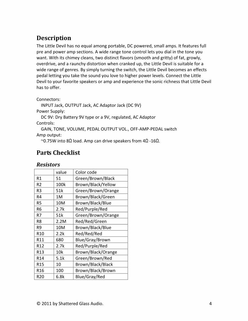
Parts Checklist
Resistors
value Color code
R1 51 Green/Brown/Black
R2 100k Brown/Black/Yellow
R3 51k Green/Brown/Orange
R4 1M Brown/Black/Green
R5 10M Brown/Black/Blue
R6 2.7k Red/Purple/Red
R7 51k Green/Brown/Orange
R8 2.2M Red/Red/Green
R9 10M Brown/Black/Blue
R10 2.2k Red/Red/Red
R11 680 Blue/Gray/Brown
R12 2.7k Red/Purple/Red
R13 10k Brown/Black/Orange
R14 5.1k Green/Brown/Red
R15 10 Brown/Black/Black
R16 100 Brown/Black/Brown
R20 6.8k Blue/Gray/Red
© 2011 by Shattered Glass Audio. 5
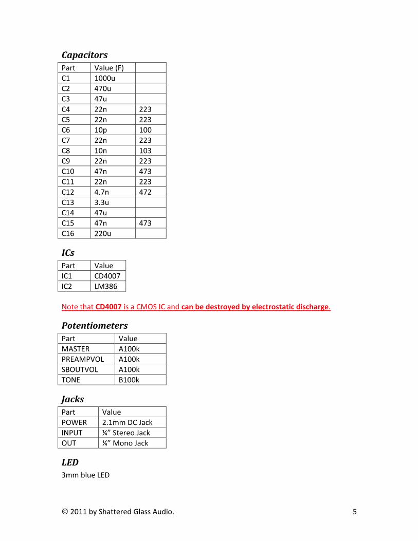
Capacitors
Part Value (F)
C1 1000u
C2 470u
C3 47u
C4 22n 223
C5 22n 223
C6 10p 100
C7 22n 223
C8 10n 103
C9 22n 223
C10 47n 473
C11 22n 223
C12 4.7n 472
C13 3.3u
C14 47u
C15 47n 473
C16 220u
ICs
Part Value
IC1 CD4007
IC2 LM386
Note that CD4007 is a CMOS IC and can be destroyed by electrostatic discharge.
Potentiometers
Part Value
MASTER A100k
PREAMPVOL A100k
SBOUTVOL A100k
TONE B100k
Jacks
Part Value
POWER 2.1mm DC Jack
INPUT ¼” Stereo Jack
OUT ¼” Mono Jack
LED
3mm blue LED

© 2011 by Shattered Glass Audio. 6
Switches
Part Value
S1 Rotary Switch
SW1 3PDT Foot Switch
Other Hardware
4 knobs with a red cap
1 knob with a silver top
Leaf Spring
9V Battery Snap
PCB
Assembly
Soldering
Little Devil is designed such that all components are soldered to the PCB.
The Following are general soldering recommendations:
- Use a soldering iron with temperature control.
- Do not spend more than 3 seconds while soldering each leg of a transistor, a
resistor, a capacitor, an IC, or a diode.
- Use an ESD safe soldering iron with temperature control when soldering CMOS
ICs and MOSFETs.
- Use a heat sink when soldering active components.
- Inspect all solder joints for completeness and cold solder.
- Ensure that components under potentiometers are fully inserted into the PCB.
- Ensure that 3PDT switch, rotary switch, DC jack, input jack, and output jack are
fully inserted into the PCB and that they vertical (i.e. at the right angle with the
PCB).
The following are general instructions on the order of soldering components to the PCB.
NB your kit may not contain all components listed below. This does not mean that your
kit is incomplete.
Solder components in the following order:
1. Sockets (if you are using them) for ICs. Sockets are not supplied with the kit. You
can purchase sockets from many online stores and they are also available at
Radio Shack.
2. Diodes – Make sure you orientate diodes such that the diode orientation
matches orientation on the PCB.
3. Resistors
4. ICs – If you are not using IC sockets, solder ICs to the PCB. Make sure that the IC
is orientated such that notch on the IC matches the notch on the PCB layout.

© 2011 by Shattered Glass Audio. 7
CMOS ICs, such as CD4007, can easily be damaged with electrostatic discharge.
To solder CMOS ICs use only an ESD safe soldering iron. The regular soldering
iron is not ESD safe and can easily destroy a CMOS IC.
5. Transistors – Make sure to orientate transistors such that the flat part of the
transistor body lines up with the flat side on the PCB. Transistors can be
damaged by prolonged exposure to heat. In addition to keeping your soldering
iron not overly hot and not spending more than 3 seconds on soldering each leg
of a transistor, we recommend that you use a heat sink clipped to a leg of the
transistor you are soldering. MOSFETs can easily be damaged with electrostatic
discharge. To solder MOSFETs use only an ESD safe soldering iron. The regular
soldering iron is not ESD safe and can easily destroy a MOSFET.
6. Ceramic Capacitors
7. Film Capacitors
8. Leaf Spring
9. PCB mounted DC jack
10. Input and Output Jacks
11. Electrolytic Capacitors – Electrolytic capacitors are polarized and need to be
properly orientated on the PCB. Make sure that the positive lead of the capacitor
is inserted into the whole with a small plus sign next to it.
12. Battery Snap – The red lead of the battery snap goes into the hole marked “+”,
whereas the black lead of the battery snap goes into the hole marked “-“ on the
PCB
13. Potentiometers – Before mounting potentiometers make sure you snap off the
tab on the side of each potentiometer. To be able to mount potentiometers onto
the PCB you may need to straighten and adjust legs of a potentiometer. Mount
each potentiometer such that it matches the outline on the PCB.
14. Rotary Switch – To be able to insert the rotary switch into the PCB you might
need to straighten and adjust the pins on the bottom of the rotary switch.
15. 3PDT Foot Switch – The 3PDT Foot Switch should be inserted into the PCB such
that the longer side of solder lugs is parallel to the longer side of the board (i.e.
length of the board)
16. LED – When inserting the LED into the PCB make sure that the flat side of the
LED matches the flat side on the figure below. Lift the LED up from the PCB until
the top of the collar on the LED lines up or is slightly below the top of the body of
the potentiometers. Top of the collar of the LED should be at most ¾”-13/16”
above the PCB.
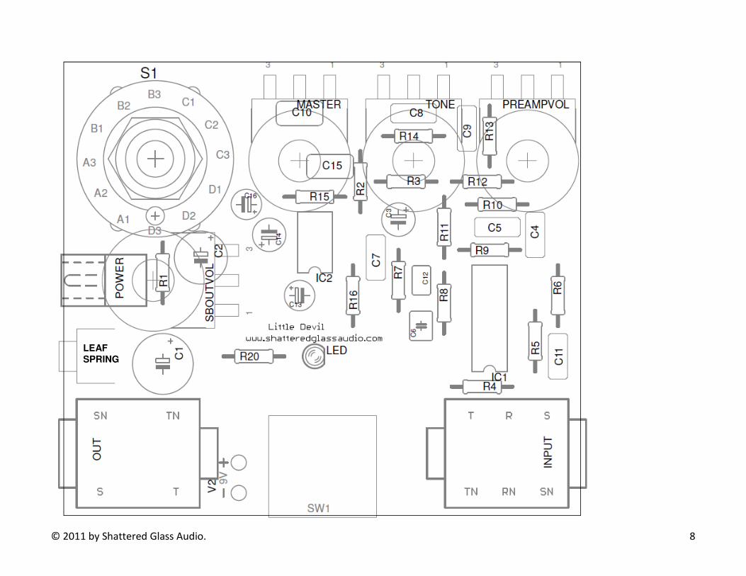
© 2011 by Shattered Glass Audio. 8
LEAF
SPRING
© 2011 by Shattered Glass Audio. 9
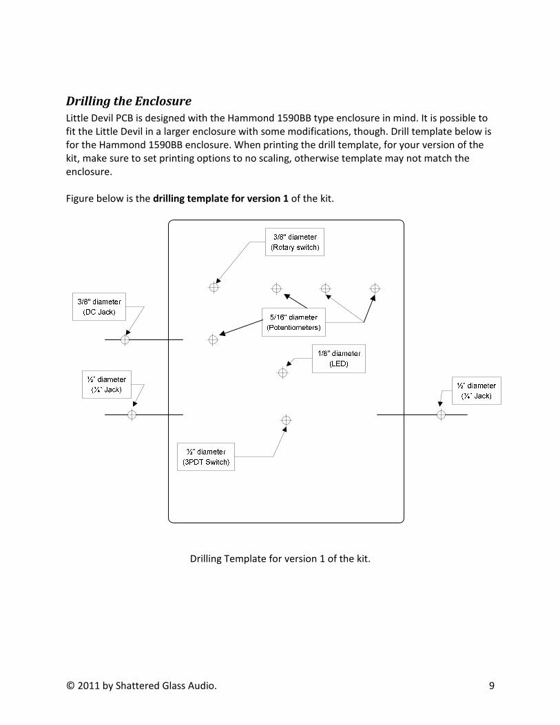
Drilling the Enclosure
Little Devil PCB is designed with the Hammond 1590BB type enclosure in mind. It is possible to
fit the Little Devil in a larger enclosure with some modifications, though. Drill template below is
for the Hammond 1590BB enclosure. When printing the drill template, for your version of the
kit, make sure to set printing options to no scaling, otherwise template may not match the
enclosure.
Figure below is the drilling template for version 1 of the kit.
Drilling Template for version 1 of the kit.

© 2011 by Shattered Glass Audio. 10
Figure below is the drilling template for version 2 of the kit.
½” diameter
(DC Jack)
½” diameter
(¼” Jack)
½” diameter
(3PDT Switch)
1/8" diameter
(LED)
5/16" diameter
(Potentiometers)
½” diameter
(¼” Jack)
3/8" diameter
(Rotary switch)
Drilling Template for version 2 of the kit.
After you have printed the template attach it to the enclosure. When attaching the template to
the enclosure make sure that the top edge of the template is aligned with the top edge of the
enclosure. Mark the holes with a center punch. Remove the template. Drill the holes.
Putting it together
After all components are soldered, the enclosure is drilled, and the faceplate/artwork is
attached you are ready to assemble the Little Devil.
Before inserting the PCB with components soldered to it, unscrew all nuts and remove all
washers from potentiometers, ¼” jacks, and the rotary switch. Unscrew the top nut and remove
the locking washer and the white washer from the 3PDT switch. Unscrew the bottom nut on

© 2011 by Shattered Glass Audio. 11
the 3PDT switch until it is about ½”- ¾” above the PCB. Insert the PCB into enclosure making
sure that potentiometers shafts, LED, and 3PDT switch shaft go into appropriate holes. First,
screw in nuts and washers of the ¼” jacks starting with the jack on the side of the spring leaf.
Tighten the nuts of the ¼” jacks with your fingers until you cannot turn the nuts any more. Do
not use tools to tighten the nuts on ¼” jacks. Over tightening the nuts on the ¼” jacks will cause
the PCB to bend. Next, screw on washers and nuts for the potentiometers, making sure that
nuts are screwed on tightly. With your finger unscrew the nut that is on the shaft of the 3PDT
switch, inside the enclosure, until it touches the roof of the enclosure. Now, screw on nut and
washers for the 3PDT switch.
Assembling the Enclosure Mounted DC jack (version 2 of the kit only)
The following section applies only to version 2 of the kit, only. Strip and tin both ends of each
wire. Solder one end of each wire to the DC jack according to the figure below.
Center Pin
(Black wire)
Sleeve
(Red wire)
Sleeve (switched)
(Red wire)
© 2011 by Shattered Glass Audio. 12
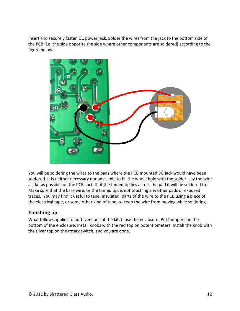
Insert and securely fasten DC power jack. Solder the wires from the jack to the bottom side of
the PCB (i.e. the side opposite the side where other components are soldered) according to the
figure below.
You will be soldering the wires to the pads where the PCB mounted DC jack would have been
soldered. It is neither necessary nor advisable to fill the whole hole with the solder. Lay the wire
as flat as possible on the PCB such that the tinned tip lies across the pad it will be soldered to.
Make sure that the bare wire, or the tinned tip, is not touching any other pads or exposed
traces. You may find it useful to tape, insulated, parts of the wire to the PCB using a piece of
the electrical tape, or some other kind of tape, to keep the wire from moving while soldering.
Finishing up
What follows applies to both versions of the kit. Close the enclosure. Put bumpers on the
bottom of the enclosure. Install knobs with the red top on potentiometers. Install the knob with
the silver top on the rotary switch, and you are done.

© 2011 by Shattered Glass Audio. 13
Operation Little Devil is designed to operate on 9V by using either a 9V battery or a regulated, center-
negative, 9V power supply, such as BOSS PSA-120.
Little Devil can be operated either as an amplifier or as an effects pedal. The knob with the
silver top in the picture below is used to select the mode of operation and to turn the Little
Devil off. In addition to the mode selection switch there are four other controls GAIN, TONE,
VOLUME, and PEDAL OUTPUT VOL.
Selection Switch
To operate the Little Devil as an amp set the selection switch to point to “AMP” and connect
your speakers to the “OUT” jack.
To operate the Little Devil as an effects pedal set the selection switch to point to “PEDAL” and
connect your amp to the “OUT” jack.
To turn the Little Devil off set the selection switch to point to “OFF”. When running on battery,
the Little Devil can also be turned off by unplugging the guitar cord.
GAIN
GAIN acts as a preamp volume. It controls the gain of the preamp section of the Little Devil.
© 2011 by Shattered Glass Audio. 14
TONE
TONE controls frequency shaping.
VOLUME
VOLUME acts as a master volume. It controls the overall volume of Little Devil’s power section.
PEDAL OUTPUT VOL.
PEDAL OUTPUT VOL. is active only in the PEDAL mode. It controls the output level of the Little
Devil.

© 2011 by Shattered Glass Audio. 15
Precautions
Location
Using the unit in the following locations can result in a malfunction:
- In direct sunlight
- In rain
- Location of extreme temperature or humidity
- Excessively dusty or dirty locations
- Locations of excessive vibrations
- Close to magnetic fields
Power supply
Be sure to unplug the power supply when the unit is not in use. Remove battery in order to
prevent it from leaking when the unit is not in use for extended periods.
Interference with other electronic devices
Radios and television sets placed nearby this unit may experience reception interference.
Handling
To avoid breakage, do not apply excessive force to the switches, potentiometers, or controls.
Keeping foreign matter out of your equipment
Never set any container with liquid in it near this equipment. If liquid gets into the equipment,
it could cause a breakdown, fire, or electric shock. Be careful not to let metal objects into the
equipment.