Embed Size (px)
Citation preview

1
LitLion Chemical - Team 15 The Chemical Engineering Department, The Pennsylvania State University,
University Park, PA, 16802
Presented by: Sarah Ramzy, Daniel Cordova, Brian Klapat, Alexander Hatza
Date: April 21st, 2017

2
Executive Summary
A pipeline quality natural gas feed is provided to the Philadelphia, Pennsylvania plant at a
temperature of 80 oF and a pressure of 400 psia. The feed comes in at 49269 pounds per hour, and
is converted to 79106 pounds per hour of 99.89% pure methanol. The team investigated many
design options to produce the highest purity methanol product while accounting for financial
constraints. The final process consists of many subunits which play a crucial role in every step.
The Mercury Removal Unit (MRU) is used to adsorb mercury, a corrosive component, from the
feed. Next, the Amine Treatment Tower enables the removal of hydrogen sulfide, a chemical that
is corrosive and can potentially poison catalysts downstream, via the use of MDEA. The pre-
reformer breaks down larger hydrocarbon chains and forms methane which works to maximize the
conversion of hydrocarbons to synthesis gas in the steam reformer. There are two separator units,
a recycle stream, and a few purging points that work together to remove any unnecessary
byproducts and reuse any valuable assets. A fired heater heats the process stream before entry into
the primary Steam Reformer where the hydrocarbons are broken down to synthesis gas. Following
the steam reformer, the process stream enters the Packed Bed Reactor (PBR) where it undergoes
catalyst-facilitated Fischer-Tropsch synthesis to create the methanol product. Finally, the methanol
product is purified by two identical distillation towers in parallel and pumped to product storage.
The kinetic data used for the reactions was found in provided literature materials.
According to the capital estimate for the project, the plan would require an initial capital
investment of $149 million dollars. This figure includes the equipment cost, site development,
contractor costs, catalyst costs, raw material costs and contingency costs for unforeseen
circumstances. The largest equipment cost is the compressors and expanders ($19.2 million) while
the largest OBL cost is raw material purchasing and product storage ($22.7 million). Operating
costs are also very high with significant utility costs coming from a refrigeration unit and large
amounts of costly waste water disposal.
The economic evaluation of the plant does not currently reflect an economically successful
process. The final After Tax Rate of Return is 7.26%, falling short of our target ATROR of 12%.
The net present value of the plant is, accordingly, -$13.4 million. The analysis used a product price
of 12.5 c/lb product and raw material costs of 2.73 c/lb product. These figures were calculated
based on provided values from NitLion Chemicals. In order for the plant to reach the target
ATROR and a positive net present value, the product price would need to increase to 13.92 c/lb
product (an 11.26% increase).
Following a series of sensitivity analyses and an alternative process study, the team would not
recommend that the plant be built as currently designed. Neither the alternative process study nor
the sensitivity analyses revealed any attainable avenue toward economic success. The team would
recommend that Research and Development at NitLion Chemicals work to find a way to increase
reaction conversion for methanol synthesis, avoid the use of costly refrigeration units, and work
to decrease the amount of water required to achieve high conversion rates in the process before
moving forward with the Philadelphia methanol plant.

3
Table of Contents
Background Information ................................................................................................................. 5
Project Background ..................................................................................................................... 5
Technical Information ................................................................................................................. 5
Reactions ..................................................................................................................................... 5
Technological Process Challenges .............................................................................................. 6
Economic Process Challenges ..................................................................................................... 7
Base Case Block Flow Diagram ..................................................................................................... 8
Process Overview and Key Design Variables ................................................................................ 9
Reactors ..................................................................................................................................... 10
Separation Units ........................................................................................................................ 12
Process Variable Controls ......................................................................................................... 15
Safety and Environmental ............................................................................................................. 17
Process Flow Diagram (PFD) ....................................................................................................... 21
Part 1 – MRU, ATU, and Pre-reformer ..................................................................................... 21
Part 2 – Steam Reformer and Separator 1 ................................................................................. 22
Part 3 - Methanol Synthesis Reactor and Separator .................................................................. 23
Part 4 – Distillation Columns .................................................................................................... 24
Process Controls............................................................................................................................ 25
Mass Balance ................................................................................................................................ 26
Energy Balance ............................................................................................................................. 30
Equipment Sizing .......................................................................................................................... 33
Reactors ..................................................................................................................................... 33
Separators .................................................................................................................................. 35
Heat Exchangers ........................................................................................................................ 38
Compressors, Expanders, and Pumps ....................................................................................... 42
Distillation Towers .................................................................................................................... 45
Utility Balance .............................................................................................................................. 49
Outside Battery Limits .................................................................................................................. 51
Economic Analysis ....................................................................................................................... 52
Alternate Process Studies .............................................................................................................. 65

4
HYSYS Model Verification .......................................................................................................... 69
Project Definition Rating Index (PDRI) ....................................................................................... 70
PDRI 1 ....................................................................................................................................... 70
PDRI 2 ....................................................................................................................................... 71
PDRI 2i ...................................................................................................................................... 72
Assumptions .................................................................................................................................. 73
Outstanding Issues ........................................................................................................................ 74
Conclusions and Recommendations ............................................................................................. 75
Acknowledgements ....................................................................................................................... 76
Research/References ..................................................................................................................... 77
References: ................................................................................................................................ 78
Appendix A ................................................................................................................................... 80
Equilibrium Data ....................................................................................................................... 80
HYSYS Model .......................................................................................................................... 81
HYSYS Model Continued ..................................................................................................... 82
HYSYS Model Verification ...................................................................................................... 83
Chemical Properties Table ........................................................................................................ 85
Component Data ........................................................................................................................ 87
Initial BFD Created – Gate 1..................................................................................................... 92
Code of Ethics ........................................................................................................................... 94
Appendix B ................................................................................................................................... 97
PDRI – Score Chart Summary .................................................................................................. 97
Appendix C- Supporting Files .................................................................................................... 101
Cash Flow Models ................................................................................................................... 101
Capital Equipment List and Sizes ........................................................................................... 107
Detailed Energy Balance ......................................................................................................... 109
Sizing and Specification Sheets .............................................................................................. 121
HYSYS Model Printout .......................................................................................................... 239
5
Background Information
Project Background
To design a chemical plant that achieves a 99.85% Methanol product purity from a feed stream of
natural gas that has already been processed to pipeline quality given a feed at 80 oF and
400 psia. Our team was assigned a raw natural gas feed of 25 MMSCFD. This equals about
approximately 40000 lbm/hr of methane. The plant must achieve 90 mol% conversion of this feed.
This is approximately 71500 lbm/hr of methanol product. The methanol product must be delivered
in a liquid phase to be shipped. Natural gas undergoes a process that involves mercury and sulfur
removal, steam reforming, and methanol synthesis.
Technical Information
Due to the feed containing mercury and hydrogen sulfide inherently, pretreatment must be
performed. The mercury removal unit is modeled as an adsorber, while the hydrogen sulfide
removal unit uses the amine MDEA (Methyldiethanolamine). Steam reforming is the process of
converting methane to CO and H2, or syngas, through a catalytic driven reaction. This is known as
steam reforming because steam must be fed with the natural gas. This process is very well known
and is practiced regularly in refineries. This process will be utilizing the Katalco 57-4Q catalyst.
The methanol is synthesized in this process by use of the Fischer-Tropsch process. Here, methanol
is formed from syngas. This is also a very well-known process that is practiced every day. This
process will be utilizing the Katalco 51-7 catalyst. To achieve the purity of the product, distillation
columns will be used. The following reactions were considered in this process.
Reactions
Steam Reforming:
CH4 + H2O ↔ CO + 3H2, ΔHrxn = 206 kJ/mol
C2H6 + 2 H2O ↔ 2CO + 5H2, ΔHrxn = 347 kJ/mol
C3H8 + 3H2O ↔ 3CO + 7H2, ΔHrxn = 497 kJ/mol
CnHm + nH2O ↔ nCO + (m-1) H2
Secondary Steam Reforming:
2H2 + O2 → 2H2O, ΔHrxn = -482 kJ/mol
CH4 + H2O ↔ CO + 3H2, ΔHrxn = 206 kJ/mol
Water Gas Shift (WGS):
CO + H2O ↔ CO2 + H2, ΔHrxn = -41 kJ/mol
Methanol Reaction:
CO + 2 H2 ↔ CH3OH, ΔHrxn = -91 kJ/mol
CO2 + 3 H2 ↔ CH3OH + H2O

6
Methyl Formate Formation
2CO + 2H2 ↔ CH3COOH
Ethanol Formation
2CO + 4H2 ↔ CH5OH + H2O
Other information
Sulfur
Sulfur specification is < 1ppm to avoid poisoning of catalyst. If used assume H2S absorption is
irreversible. Beds are not regenerated.
Mercury
Mercury is a catalyst poison. If used, assume Mercury absorption is irreversible. Beds are not
regenerated.
Methanol Synthesis Reaction
The following table shows the selectivity for the MeOH reaction.
Table 1: Selectivity for Methanol Synthesis Reaction
Chemical Name Formula Wt. %
Methanol CH3OH 99.60
Ethanol C2H5OH 0.25
Methyl formate HCOOCH3 0.15
Technological Process Challenges
A majority of the technological process challenges project lie within the reactors. The steam
reforming reactor requires a very high temperature and large amount of steam to get the necessary
conversion in this reactor. Steam reforming is an endothermic reaction. Therefore, not only does
the feed need to be heated to a high temperature, this temperature needs to be maintained
throughout the reactor. Also, due to this high temperature, fired heaters must be used to reach the
process conditions. Fired heaters are both expensive to purchase and to operate. The methanol
synthesis reactor also has its drawbacks. This reactor requires a very high pressure to achieve a
better conversion. To achieve this pressure, the use of compressors is needed. Compressors are
very expensive and add a large cost to the over IBL capital costs. A higher pressure also affects
the downstream equipment, due to needing to purchase equipment that is rated for these operating
conditions. The catalyst used for this system also does not yield a very strong conversion of syngas.
Therefore, other measures must be taken to reach the hard specifications. These operating
conditions are defined, and we cannot deviate from them.

7
Economic Process Challenges
The main challenge in this project is the lower product sales price of methanol. There is a large
amount of equipment needed for this process. This leads to a large capital costs. A large upfront
cost is hard to come back from when considering the annual operating costs and the depreciation
of the dollar. If the company cannot make a large enough profit each year, they will end up not
having a positive net present worth at the end of the project. The use of refrigeration adds a huge
annual utility cost, which will be a hard cost to overcome with the current product price.

8
Base Case Block Flow Diagram

9
Process Overview and Key Design Variables
Hard Specifications
The hard specifications are that the product must be 99.85 wt% pure Methanol at a production rate
of at least 71500 lbm/hour.
The methanol production process has been modeled in ASPEN HYSYS. Images of this simulation
are shown in the Appendix. HYSYS does not show how the actual plant would be modeled, it
shows a simplification of the processes. This allows for the mathematical calculations to be
determined by the software.
Mercury Removal Unit (MRU)
This unit has been implemented because Mercury, even at low levels, has been known to damage
aluminum heat exchangers to the point of catastrophic failure. Not only can it damage some heat
exchangers, but mercury can hinder other separations down the line. Therefore, the MRU was
placed first to try to limit corrosion and damage throughout the process. Mercury is adsorbed to a
substrate which will be replaced over time as the substrate saturates. In HYSYS, the MRU is
modeled as a component splitter. This allows for the components to be separated to a set value.
This value has been determined through literature. The key design variables of this unit include
the run time, number of units, length and diameter. All of this are important to ensure that the
mercury is properly removed from the natural gas feed.
• Based on 7-day operation
• Number of units: 3
• Length (L): 10.42 ft
• Diameter (D): 3.47 ft
• L/D = 3.00
• Volume: 90.65 ft3
Amine Treatment Unit (ATU)
This unit has been implemented to remove the Sulfur from the system. This utilizes amines to
“sweeten” sour gas, creating sweet gas. Sweet gas is necessary to have, because sour gas is
corrosive and sulfur in the stream would poison the reforming catalysts later in the process. This
unit is a single pass process. In HYSYS, the ATU is modeled as a component splitter. This allows
for the components to be separated to a set value. This value has been determined through
literature.
A key design variable is the MDEA solution flow into the ATU.
• Residence time: 15 min
• MDEA flow rate: 93.5 gpm
• Pressure: 385 psig
• MDEA/Water solution Flow Rate: 240.8 gpm
• MDEA Inlet Temperature: 40 °F
• MDEA Outlet Temperature: 52.43 °F

10
Reactors
Pre-Reformer
This is used to convert the heavy hydrocarbons contained within the sweet gas into syngas and
methane to increase the overall conversion in the steam reformation reactor. The conversion for
these heavy hydrocarbons is 100%. In HYSYS, this is modeled as a conversion reactor. This allows
for the conversion of the reactions to be set manually. This is actually a packed bed reactor utilizing
a Nickel-based catalyst.
These temperatures have been chosen because this reflects where the data for the pre-reformer is
accurate. Also, this utilizes the pressure of the feed, thus, we do not need to install expensive
equipment to change this condition this unit is cooled by cooling water, and to ensure it remains
isothermal.
• Operating Temperature: 500 °F
• Operating pressure: 385 psig
Steam Reformer
This unit utilizes the sweet gas and a steam feed to create Synthesis gas (Syngas), CO and H2. In
HYSYS, this is modeled as packed bed reactor. This unit is operated at 1100 oF and 15.3 psig. The
temperature was determined through simulation data from HYSYS, finding this temperature to
yield high conversion. The pressure was determined from a literature review performed on the
process. These process conditions were chosen because they are within the range for the kinetic
data, which has been obtained from literature. The steam reforming reaction is endothermic;
therefore, this unit must be heated to maintain the operating temperature. The catalyst used is
Nickel-based. The overall conversion of the methane in this reactor is approximately 89%.
The steam reformer in HYSYS is modeled as a packed bed reactor. These temperatures have been
chosen because this reflects where the data for the reformer is accurate. Increasing the temperature
at the outlet would increase the overall conversion, but the kinetic data is not supported at a
temperature higher than 1139 F. This operating temperature was chosen based on figure 3, showing
the conversion of methane as function of temperature. If the operating temperature could be
increased further, the conversion would increase as well. The pressure chosen reflects the most
applicable value in reference to the literature. This unit requires a very large amount of water to
obtain the necessary conversion of methane. The H2O/CH4 ratio chosen is out of the normal range,
but it is necessary to convert enough methane with the temperature restrictions.
One drawback of operating at these high temperatures is the need for such a large amount of heat
to be added to maintain the isothermal conditions. The fuel for this system is expensive, and adds
a large expense to yearly utility costs. A second drawback is the need to add a refractory inner
coating to the reactor. This is done to withstand the high temperatures within the reactor. This adds
an additional amount to the overall capital cost for this piece of equipment. The final drawback is
the large amount of water required to operate this unit. At these conditions, 150,000 lb/hr of water
needs to be pumped into the system, and the overall recycle within the system is approximately
400,000 lb/hr. This enables for the conversion to be relatively high. However, due to this enormous
amount of water, the size of the reactor must increase. This not only affects the size of the reactor,
but it affects the amount of catalyst needed and other equipment downstream.

11
• Inlet Temperature: 1100 °F
• Outlet Temperature: 1100 °F
• Operating Pressure: 15 psig
• H2O/CH4 ratio: 12.35
• Heat Required: 280 MMBTU/hr
Figure 1: SMR Reactor data at varying temperatures.
Methanol Synthesis
This unit is a catalyst packed bed reactor to create Methanol from Syngas. This reactor has a
selectivity of 99.6%. The other 0.4% forms methyl formate and ethanol. This unit is operated at
500 F and 1000 psig. These process conditions were chosen because they reflect the greatest
conversion of CO to methanol, while being within the specifications of the catalyst’s activity. In
HYSYS, this is modeled as a conversion reactor. The conversion of the Methanol synthesis
reaction is currently set at 18%. The CO2 in the stream, which was formed from the Steam
Reformer, also creates methanol. The conversion of this is very high, because this is a very
favorable reaction. In conjunction, the two reactions create approximately 79100 lb/hr of methanol.
The temperatures are key design variable because they are applicable to the model given. This
reactor is modeled as packed bed reactor. This reactor requires a cooling jacket to maintain the
outlet temperature. The kinetic data for the catalyst does not support a value above 520 °F. The
inlet temperature was set to 500 °F to allow for the exothermic reaction to take place, and limit the
cooling needed for the process stream. This system is operated a very high pressure. This allows
for the greatest conversion of syngas to methanol.
The drawback of operating at this pressure is the need to compress the feed stream and expand the
product for further processing. Compressors have the largest capital cost in the design. However,
as pressure decreases, so does the conversion of CO. Thus, this is a necessary action.
20
30
40
50
60
70
80
90
100
800 850 900 950 1000 1050 1100 1150
Met
han
e C
onver
sio
n (
%)
Inlet/Outlet Temperature (F)
SMR Reactor Temperature vs Conversion %

12
• Inlet Temperature: 500 °F
• Outlet Temperature: 520 °F
• Operating Pressure: 1000 psig
Separation Units
Separator 1 (V-101)
This unit is a two-phase Vapor-Liquid separator drum located after the Steam Reformer. The feed
into this tower has been cooled down to separate out a large portion of the water at this stage, so it
can be recycled. The lighter gases and the remaining water is separated into the vapor phase, where
it is used further in the process. The following are the key design variables for the vapor-liquid
separator. In order to achieve the separation enough residence time should be allowed to have an
effective separation.
• Settling Velocity: 8.14 ft/s
• Residence time: 25 min
• Vessel diameter (d): 10.6 ft
• Length (L): 31.7 ft
• L/d: 3
• Demister height: 0.5 ft
Separator 2 (V-100)
This unit is a two-phase vapor-liquid separator tower located after the Methanol Synthesis Reactor.
This is used to separate the lighter gases from the heavier liquids. Almost all of the gases in the
system are removed with this separator. This allows for the equipment down the line to be smaller,
due to less mass flow going into it. Also, by removing a majority of the light gases from the system,
the distillation columns have an easier separation, yielding a purer product. The same key design
variables apply to this separator:
• Settling Velocity: 9.71 ft/s
• Residence time (liquid hold-up): 10 min
• Vessel diameter (d): 7.1 ft
• Length (L): 21.2 ft
• L/d: 3
• Demister height: 0.5 ft
Distillation Columns 1 and 2
These distillation towers are used to separate out the methanol product to a 99.85 wt% purity. Two
distillation towers are required to be operated in parallel for this separation to occur. The feed
stream is split into two identical streams, halving the flowrate. Each column requires 40 trays, and
have reflux ratios of 4.5. These feed stream is fed into the middle of the column at 206.7 F and 15

13
psig. This temperature is chosen because it best reflects the temperature of the feed tray. This
prevents excessive flooding in the column. This pressure is chosen to prevent backpressure in the
column during startup. The trays are chosen to be sieve trays, with a tray spacing of 15 inches.
These columns are able to achieve all hard specifications needed.
T-100:
• Theoretical Stages: 40
• Inlet Temperature: 207 °F
• Inlet Pressure: 30 psia
• Bottoms Temperature: 228°F
• Bottoms Pressure: 29 psia
• Distillate Temperature: 175 °F
• Distillate Pressure: 24.5 psia
• Reflux Ratio: 4.1
T-103:
• Theoretical Stages: 40
• Inlet Temperature: 207 °F
• Inlet Pressure: 30 psia
• Bottoms Temperature: 228 °F
• Bottoms Pressure: 29 psia
• Distillate Temperature: 175 °F
• Distillate Pressure: 24.5 psia
• Reflux Ratio: 4.1
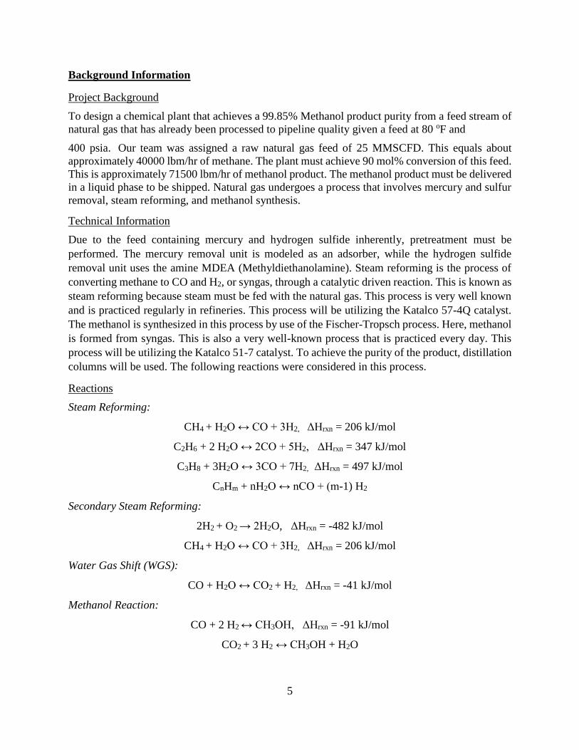
In order to obtain an initial guess for the theoretical number of stages we used the McCabe Thiele
diagram. Based on this diagram, the theoretical number of stages is 11. However, this module is
under the assumption of infinite reflux which is not the case. As a result of this assumption, the
model underestimates the number of theoretical stages. The theoretical number of trays was
determined to be 40 plates using HYSYS.
14
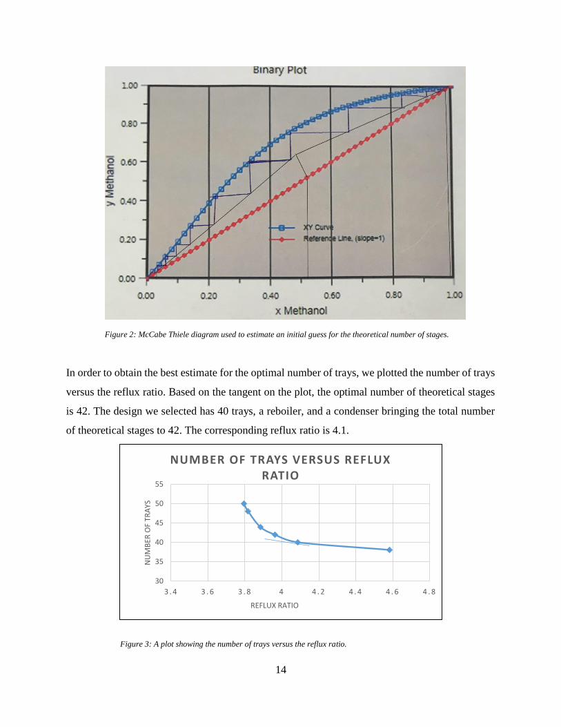
In order to obtain the best estimate for the optimal number of trays, we plotted the number of trays
versus the reflux ratio. Based on the tangent on the plot, the optimal number of theoretical stages
is 42. The design we selected has 40 trays, a reboiler, and a condenser bringing the total number
of theoretical stages to 42. The corresponding reflux ratio is 4.1.
30
35
40
45
50
55
3 . 4 3 . 6 3 . 8 4 4 . 2 4 . 4 4 . 6 4 . 8
NU
MB
ER O
F TR
AYS
REFLUX RATIO
NUMBER OF TRAYS VERSUS REFLUX RATIO
Figure 3: A plot showing the number of trays versus the reflux ratio.
Figure 2: McCabe Thiele diagram used to estimate an initial guess for the theoretical number of stages.
15
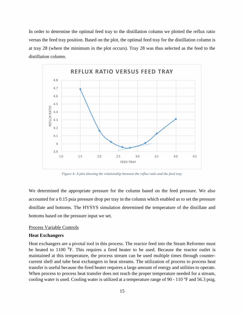
In order to determine the optimal feed tray to the distillation column we plotted the reflux ratio
versus the feed tray position. Based on the plot, the optimal feed tray for the distillation column is
at tray 28 (where the minimum in the plot occurs). Tray 28 was thus selected as the feed to the
distillation column.
Figure 4: A plot showing the relationship between the reflux ratio and the feed tray.
We determined the appropriate pressure for the column based on the feed pressure. We also
accounted for a 0.15 psia pressure drop per tray in the column which enabled us to set the pressure
distillate and bottoms. The HYSYS simulation determined the temperature of the distillate and
bottoms based on the pressure input we set.
Process Variable Controls
Heat Exchangers
Heat exchangers are a pivotal tool in this process. The reactor feed into the Steam Reformer must
be heated to 1100 ⁰F. This requires a fired heater to be used. Because the reactor outlet is
maintained at this temperature, the process stream can be used multiple times through counter-
current shell and tube heat exchangers to heat streams. The utilization of process to process heat
transfer is useful because the fired heater requires a large amount of energy and utilities to operate.
When process to process heat transfer does not reach the proper temperature needed for a stream,
cooling water is used. Cooling water is utilized at a temperature range of 90 - 110 oF and 56.3 psig.
3.9
4
4.1
4.2
4.3
4.4
4.5
4.6
4.7
4.8
1 0 1 5 2 0 2 5 3 0 3 5 4 0 4 5
REF
LUX
RA
TIO
FEED TRAY
REFLUX RATIO VERSUS FEED TRAY
16
These utility streams are used in multiple counter-current shell and tube heat exchangers to produce
the temperatures desired.
Compressors, Expanders, and Pumps
The pressure of the streams can be controlled through the use of compressors, expanders, and
valves. The natural gas feed comes into the system at 385.4 psig. This must be lowered to enter
the prereformer, due to where the kinetic values have been defined at. An expander is used to
release the pressure of the stream to 15.3 psig, capturing the energy. This energy can be reused
later to power a process. The stream needs to be repressurized, but this time to 1000 psig, to enter
the methanol synthesis reactor. This is done by a two stage compressing and cooling. A pressure
ratio of 6 is maintained through these compressors, to achieve the desired pressure. Another
expander is used to depressurize the stream to 15.6 psig, so it can be separated more efficiently.
Two pumps are required to pump the product and waste water to their respective storage/treatment
facilities. The first pump must pressurize the product streams to 85 psig so it can travel the 1-mile
distance to the storage tank farm, and the second pump must pressurize all waste water to 35 psig
so it can be taken to the bio-treatment area.

17
Safety and Environmental
General Safety
A safe working environment is one of the most important factors when designing a chemical plant.
Although the process will be mostly automated, any people on the site will wear proper personal
protective equipment (PPE). Due to the flammability of many chemicals that are present in the
plant, such as methane, all equipment must be properly grounded or bonded. To further reduce the
chance of fire or explosion, smoking will not be permitted on company grounds, and only
authorized personnel will be allowed. Regular preventive maintenance on the pipes and equipment
in the system is necessary to ensure there are no leaks. Personnel will receive the proper training
on how to respond to emergency situations in the plant. Standard operating procedures (SOP)
should be carefully followed whenever the plans needs to shut down or start up.
Major Chemicals
There are many chemicals used in this process, some of these chemicals could be harmful if not
handled properly. These chemicals are described below. All of the chemical data is tabulated in
Appendix A.
Methane:
Methane is a clear, flammable gas. Methane has an LFL of 5%, and an autoignition temperature
of 1076 °F. There is a large amount of methane in the system; thus, it is important to monitor this
chemical. The NIOSH REL-TWA is 800 ppm.
Carbon Monoxide:
Carbon monoxide is a clear, flammable gas. Carbon monoxide has an LFL of 12.5%, and an
autoignition temperature of 1128 °F. This chemical has a chance for asphyxiation. The NIOSH
REL-TWA is 35 ppm.
Ethane:
Ethane is a clear, flammable gas. Ethane has an LFL of 3%, and an autoignition temperature of
959 °F. Although this gas is a risk, there is a very small amount in the system.
Propane:
Propane is a clear, flammable gas. Propane has an LFL of 1.8%, and an autoignition temperature
of 859 °F. Although this gas is a risk, there is a very small amount in the system. . The OSHA PEL
is 1000 ppm.
N-Butane:
N-Butane is a clear, flammable gas. N-Butane has an LFL of 1.6%, and an autoignition temperature
of 761 °F. Although this gas is a risk, there is a very small amount in the system.

18
Iso-Butane:
Iso-butane is a clear, flammable gas. Iso-butane has an LFL of 1.6%, and an autoignition
temperature of 890 °F. Although this gas is a risk, there is a very small amount in the system.
N-Pentane:
N-Pentane is a clear, flammable liquid at room temperature. N-Pentane has an LFL of 1.5%, and
an autoignition temperature of 500 °F. Although this is a risk, there is a very small amount in the
system. The OSHA PEL is 1000 ppm.
Iso-Pentane:
Iso-Pentane is a clear, flammable liquid at room temperature. Iso-Pentane has an LFL of 1.4%,
and an autoignition temperature of 788 °F. Although this is a risk, there is a very small amount in
the system. The TLV-TWA is 1000 ppm.
Cyclohexane:
Cyclohexane is a clear, flammable liquid at room temperature. Cyclohexane has an LFL of 1.3%,
and an autoignition temperature of 473 °F. Although this is a risk, there is a very small amount in
the system. The OSHA PEL is 300 ppm.
Nitrogen:
Nitrogen is a clear gas. This chemical has a chance for asphyxiation; thus, it is important to ensure
there are no leaks in the system.
Hydrogen Sulfide:
Hydrogen sulfide is a clear, flammable gas. Hydrogen sulfide has an LFL of 4%, and an
autoignition temperature of 450 °F. The OSHA PEL is 20-50 ppm.
Mercury:
Mercury is a heavy, silver-white, odorless liquid. The boiling point of mercury is 674 °F. Elemental
mercury is toxic to the central and peripheral nervous systems. The inhalation of mercury vapor
can produce harmful effects on the nervous, digestive and immune systems, lungs and kidneys,
and may be fatal. The NIOSH REL TWA is 0.1 mg/m3 and 0.05 mg/m3 for liquid mercury and
mercury vapor, respectively.
Methanol:
Methanol is a clear, flammable liquid. Methanol has an LFL of 6%, and an autoignition
temperature of 878 °F. However, during our process, the methanol will not reach the autoignition

19
temperature. The methanol will his is our main product, and it is important to ensure this is safely
transported throughout the plant. The OSHA PEL is 200 ppm.
Methyl Formate:
Methyl formate is a clear, flammable liquid. Methyl formate has an LFL of 4.5%, and an
autoignition temperature of 869 °F. However, during our process, the methyl formate will not
reach the autoignition temperature. Although this is a risk, there is only a small amount of this in
our system. The NIOSH REL-TWA is 1000 ppm.
Ethanol:
Ethanol is a clear, flammable liquid. Ethanol has an LFL of 3.3%, and an autoignition temperature
of 685 °F. However, during our process, the ethanol will not reach the autoignition temperature.
Although this is a risk, there is only a small amount of this in our system. The NIOSH REL-TWA
is 1000 ppm.
Environmental Hazards
Mercury:
Mercury is a highly toxic compound which must be handled with care. The presence of mercury
in a process can lead to catalyst poisoning thus decreasing the efficiency of the plant. This deemed
the presence of a Mercury Removal Unit a necessity. Mercury can be leaked to the environment
through improper disposal techniques or faulty unit design. Such leaks can affect the quality of the
air or surrounding bodies of water. As a result, not only are the lives of humans (workers or
citizens) endangered, but also the aquatics. Solid mercurial waste emitted into the environment
commonly originates from process units dedicated to mercury removal. It is critical that mercury
waste be properly labeled and disposed of according to federal laws and regulations.
Hydrogen Sulfide:
Hydrogen Sulfide is a highly toxic and corrosive chemical. The Presence of hydrogen sulfide can
damage the piping and cause a decrease in plant efficiency as well as leaks to the environment.
Hydrogen sulfide can react with any present moisture to produce sulfuric acid which is highly
corrosive. The Sulfuric acid can lead to detrimental effects on the process and affect the health of
employees and well-being of the environment. As a result, proper precautions must be taken with
regards to designing the Amine Treatment Tower. Since sulfuric acid is highly corrosive to carbon
steel, the tower will be designed using a stainless steel lining instead. By using two materials of
construction, the risk of corrosion is reduced while minimizing the cost for this piece of equipment.
Additionally, temperature and pressure sensors will be installed prior to and immediately after the
ATU to regulate these variables. The addition of valves will ensure adjustment of pressure in case
of deviations.
Methane:
Methane is a highly flammable compound which must be monitored properly. Methane is also a
greenhouse gas with a global warming potential approximately 20 times that of carbon dioxide.
This makes methane leaks a severe threat to the environment. As result, the methane has to be

20
discarded properly. We have elected to flare the excess methane thus converting it to carbon
dioxide and hydrogen gas which has a much less damaging effect on the environment.
Methanol:
Methanol is a highly flammable. It is also considered to be a Volatile Organic Compound (VOC).
VOCs have been linked to many cases of irritations, cancer, increased emergency room visits, and
in some severe cases, premature death. Exposure can occur through inhalation or digestion.
Methanol released into the environment can also affect the wildlife including animals, fish, and
even plants. It can affect the growth of these living things and can even lead to their death.
Methanol can be transported through air or water. This makes it necessary to carry appropriate
measures to ensure proper transportation of methanol product from the plant to the storage
containers and safe delivery to the consumers’ destination. It is also crucial that the storage
containers be constructed from materials that can resist the flammability of methanol.

21
Process Flow Diagram (PFD)
Part 1 – MRU, ATU, and Pre-reformer

22
Part 2 – Steam Reformer and Separator 1

23
Part 3 - Methanol Synthesis Reactor and Separator

24
Part 4 – Distillation Columns

25
Process Controls
Process controls were added in order to control the process safely and profitably. The controllers
added to the process regulate key variables such as flow, temperature, levels, and pressure. The
Process Flow Diagram (PFD) shows key control requirements on major equipment such as heat
exchangers, separator vessels, distillation towers, and reactors.
In the process the MRU and AMU contain a pressure control system that is designed to regulate
vapor pressure. The vapor/liquid separators contain two control systems, level and pressure
control. The level control is essential in order to prevent liquid overflow in the vessel. A pressure
control system was used in order to control overpressure in the separator vessels. All of the heat
exchangers in the process are controlled by temperature controllers to ensure that the process
streams are not overheated to a point that is not safe for the equipment design specifications. Flow
controllers are used to regulate the recycle streams in the process. Distillations columns are
controlled by placing pressure controller on the condenser, temperature control on the reboiler,
and flow control on the reflux. The reactors can be regulated using temperature or pressure control
systems. Reactors also contain relief valves or rupture disks; however, these safety elements are
not shown in the PFD.

26
Mass Balance
The sheet shown in the images below is a full-process mass balance of each of the components
involved in the process. The numbers at the top of many of the columns correspond to stream
numbers from the BFD. All numbered columns are shown in lbm/hr units, but some of the
intermediary columns that involved reaction calculations are shown in lbmol/hr. All assumptions
regarding efficiency, selectivity, and conversion are shown below the rows of the mass balance in
demarcated boxes. The cells of the spreadsheet are defined using references to ensure for ease of
adjustment when changing parameters later on in the project. Each unit of the process is shown
spanning over the columns that are involved in that unit for ease of organization. The mass balance
values have been updated with the conversions, separation efficiencies, and other information from
the HYSYS simulation. The final product of this mass balance is currently a 99.89% pure stream
of MeOH flowing at 79100 lbm/hr. This final product meets both hard specifications.

27
1 2 3 4 5 6 7 8 9 10 11 12 13 14 16 17 18 19 20 21 22 23 24
NG Hg Amine MDEA Tower To aminePre
Steam into WORK CO created H2 created Remaining Water WGSWork Col CO
H2 Water CO2 createdReactor Output Water R-2 Work Col CO to MeOH WGS CO2 to MeOH NH3 R-2 Gas Purge Feed to
Feed Removed Tower feed treatment reformer Pre COL in reformer in reformer HC Used created created Consumed from Recycle Feed and side rxns Output Splitter
Component BP (F) # of C # of H MW Mol % Xi lbm/hr 1.00 Feed feed Reformer lbmol lbmol lbmol lbmol lbmol lbmol lbmol lbmol lbmol lbmol lbmol lbmol R-1 lbmol lbmol lbmol lbmol lbmol lb/hr
H2 -423 2.01588 0.00 0.00 8265.48 8.12 64.58 130.19 130.19 7657.15 15566.09 0.01 0.00 0.00 15566.08 7721.73 6857.35 8728.64 2577.87 2575.29 5191.48 5191.46 0.02 0.01 0.01 0.01 0.00 0.01 0.00 0.00
N2 -320 28.0134 1.51 0.0151 1160.72 1160.72 1160.72 1160.72 0.00 1160.72 1160.72 1160.72 0.00 0.00 0.00 1160.72 41.43 41.43 41.43 41.43 40.58 1136.65 1136.43 0.21 0.11 0.11 0.11 0.00 0.11 0.00 0.00
CO -313 28.0101 0.00 0.00 2823.03 70.58 14.12 395.37 395.40 2388.06 67285.25 0.07 0.04 0.04 67285.17 2402.18 1969.78 98.49 98.49 98.49 2758.69 2758.52 0.18 0.09 0.09 0.09 0.00 0.09 0.00 0.00
CH4 -258.7 1 4 16.0425 90.11 0.9011 39666.98 39666.98 39666.98 39666.98 0.00 2472.62 2472.62 7417.86 0.00 2472.62 2752.45 44156.20 44156.20 2752.45 2449.68 7657.15 2634.54 3868.64 0.00 0.00 0.00 3868.64 3868.64 3868.09 0.55 0.27 0.27 0.27 0.00 0.27 0.00 0.00
C2H6 -128.2 2 6 30.069 4 0.04 3300.37 3300.37 3300.37 3300.37 0.00 109.76 219.52 548.80 0.00 219.52 0.00 0.00 0.00 0.00 0.00 0.00 0.00 0.00 0.00 0.00 0.00 0.00 0.00 0.00 0.00 0.00 0.00 0.00 0.00 0.00 0.00
CO2 -110.3 44.0095 1.5 0.015 1811.43 1811.43 1811.43 1811.43 0.00 41.16 97.62 4296.23 4298.68 123.24 9722.44 4.89 2.44 2.44 9717.55 220.81 220.81 2092.10 41.84 41.84 1841.45 1807.42 34.03 17.01 17.01 17.01 0.00 17.01 0.00 0.00
H2S -77 34.0809 1.5 0.015 1402.77 1402.77 1402.77 1402.77 0.00 0.00 0.00 0.00 0.00 0.00 0.00 0.00 0.00 0.00 0.00 0.00 0.00 0.00 0.00 0.00 0.00 0.00 0.00
C3H8 -43.6 3 8 44.0956 0.9 0.009 1088.98 1088.98 1088.98 1088.98 0.00 24.70 74.09 172.87 0.00 74.09 0.00 0.00 0.00 0.00 0.00 0.00 0.00 0.00 0.00 0.00 0.00 0.00 0.00 0.00 0.00 0.00 0.00 0.00 0.00 0.00 0.00
NH3 -28 17.03052 0.00 0.00 0.00 0.00 0.00 0.00 1.72 29.27 13.80 15.47 7.74 7.74 7.74 0.00 7.74 0.00 0.00
iC4H10 11 4 10 58.124 0.2 0.002 318.98 318.98 318.98 318.98 0.00 5.49 21.95 49.39 0.00 21.95 0.00 0.00 0.00 0.00 0.00 0.00 0.00 0.00 0.00 0.00 0.00 0.00 0.00 0.00 0.00 0.00 0.00 0.00 0.00 0.00 0.00
nC4H10 31 4 10 58.124 0.1 0.001 159.49 159.49 159.49 159.49 0.00 2.74 10.98 24.70 0.00 10.98 0.00 0.00 0.00 0.00 0.00 0.00 0.00 0.00 0.00 0.00 0.00 0.00 0.00 0.00 0.00 0.00 0.00 0.00 0.00 0.00 0.00
iC5H12 82 5 12 72.1488 0.1 0.001 197.98 197.98 197.98 197.98 0.00 2.74 13.72 30.18 0.00 13.72 0.00 0.00 0.00 0.00 0.00 0.00 0.00 0.00 0.00 0.00 0.00 0.00 0.00 0.00 0.00 0.00 0.00 0.00 0.00 0.00 0.00
HCOOCH3 89 2 4 60.052 0.00 0.00 0.00 0.00 0.00 0.00 0.20 0.20 0.20 0.20 12.15 4.90 7.24 3.62 3.62 3.62 0.00 3.62 0.00 0.00
nC5H12 97 5 12 72.1488 0.05 0.0005 98.99 98.99 98.99 98.99 0.00 1.37 6.86 15.09 0.00 6.86 0.00 0.00 0.00 0.00 0.00 0.00 0.00 0.00 0.00 0.00 0.00 0.00 0.00 0.00 0.00 0.00 0.00 0.00 0.00 0.00 0.00
CH3OH 148.5 1 4 32.0419 0.00 0.00 0.00 0.00 0.00 0.00 430.84 2050.26 2481.10 79499.07 151.49 79347.58 39673.79 39673.79 39511.18 162.61 39511.18 162.61 0.00
C2H5OH 173 2 6 46.06844 0.00 0.00 0.00 0.00 0.00 0.00 0.57 0.57 0.57 0.57 26.45 0.26 26.19 13.09 13.09 13.09 0.00 13.09 0.00 0.00
C6H12 177 6 12 84.16595 0.02 0.0002 46.19 46.19 46.19 46.19 0.00 0.55 3.29 6.59 0.00 3.29 0.00 0.00 0.00 0.00 0.00 0.00 0.00 0.00 0.00 0.00 0.00 0.00 0.00 0.00 0.00 0.00 0.00 0.00 0.00 0.00 0.00
H2O 212 18.01528 0.01 0.0001 4.94 4.94 4.94 72062.10 72062.10 4.94 150000.00 8326.54 5503.51 8255.96 8199.50 147716.35 555054.14 30810.19 28175.64 507592.11 471299.06 63961.27 407337.79 36293.05 2014.57 2015.14 143.85 2194.11 2194.11 39527.48 73.82 39453.66 19726.83 19726.83 0.07 19726.76 0.07 19726.76 0.00
MDEA 476.6 119.163 52182.90 52182.90 0.00 0.00 0.00 0.00 0.00 0.00 0.00 0.00 0.00 0.00 0.00
Hg 674 200.592 0.002 0.00002 11.01 11.01 11.01 0.00 0.00 0.00 0.00 0.00 0.00 0.00 0.00 0.00 0.00 0.00 0.00 0.00 0.00 0.00 0.00 0.00 0.00
SUM Total 49269 11 49258 124245 125648 47855 150000 197855 605195 33563 4838 605195 471304 63964 407340 133891 133891 15006 118885 59443 59443 39553 19889 39553 19889 0.0
197855 0 MeOH purity: 0.9989 MeOH purity: 0.9989
New Data for MeOH Reactor mol%
Assume 96% conversion for CO2 to MeOH CO and CO2 to MeOH 0.99445 0.996409231 At 350 F Total Product: 79106 lb/h
89% 0.89 Conversion 93 (Combined weight conversion) 100% CO2
stream 1 NG feed 49269 stream 2 Hg removed 11.01 REFORM CnHm+nH20 --> nCO + (n+1/m)H2 0.2% 0.002 Ethanol 0.00381 0.002655183 Distillate:
4 MDEA/Water 124245 5 S removed 125647.77 CO to Me CO+3 H2 --> CH4 + H2O 0.4% 4.00E-03 Assume 95% conversion for Water Gas Shift Reaction M-Formate 0.00175 0.000935586 MeOH removal (95%) 0.9999 103742
7 Water 150000.000 12 Water Purge 63963.75 WGS CO+H2O --> CO2+H2 Conversion 0.95 Overall Conv Basis 100% of light impurities come out in Distillate 0.1
25 MMSCFD 80 F 17 Gas Purge 15006.18 WGS CO+H2O --> CO2+H2 95.00% CO Bottoms:
2744 lbmol/hr 400 psia 21 MeOH out 1 39553.19 mol% Conversion (%) Assume 90% conversion for N2 to ammonia reaction CO MeOH CO+2 H2 --> CH3OH 18.0% CO Assume 99.99% C6H12 removal 0.95
22 EtOH + water 1 19889.37 Methanol CH3OH 0.996 0.99745 0.9475775 Conversion 0.05 CO2 MeOH CO2+3 H2 --> CH3OH + H2O 98.00% H2 Assume 99.99% H2O removal 0.9999
23 MeOH out 2 39553.19 Ethanol C2H5OH 0.0025 0.00174 0.001653 EtOH 2CO+4 H2 --> C2H5OH + H2O 0.20% CO Assume 99.99% Hg removal 0.9999
24 EtOH + water 2 19889.37 Methyl Formate HCOOCH3 0.0015 0.000801 0.00076095 0.95 Recycle Ratio (from HYSYS) M Form 2 CO+ 2H2 --> HCOOCH3 0.09% CO Assume 99.99% C2H5OH 0.9
323514 323514 NH3 N2+3H2 --> 2 NH3 0.10% H2
H2O % 58%
MDEA % 42% 0.864287302
Fed 56.25 m^3/h
MDEA 52182.9 lbm/h CnHm to CO and H2 1
H2O 72062.1 lbm/h 97.9% methanation CO basis 0.975 Cmpd Separation Fraction Cmpd Sep Frac Cmpd Sep Frac
5% water/gas CO basis 0.02 Methane 3.15E-07 Methane 0.999858662 Methane 0.999990423
Reforming Rxns ΔH 5% unreacted CO, H2 CO basis H2O 9.28E-01 H2O 0.001867591 H2O 3.37504E-06
CH4 206 kJ/mol Ethane 1.46E-08 Ethane 0.999867412 Ethane 0.999996758
C2H6 347 kJ/mol CO2 5.03E-04 CO2 0.981522045 CO2 0.999997535
C3H8 497 kJ/mol Nitrogen 2.72E-06 Nitrogen 0.999812273 Nitrogen 0.999979051
WGS -41 kJ/mol 0.9 Propane 2.21E-10 Propane 0.999959365 Propane 0.999998188
methanating -206 kJ/mol at 206 i-Butane 1.87E-12 i-Butane 0.999994304 i-Butane 0.999998421
n-Butane 2.79E-12 n-Butane 0.999988783 n-Butane 0.99999895
i-Pentane 1.86E-14 i-Pentane 0.999998316 i-Pentane 0.999999266
Rate Conv n-Pentane 2.04E-14 n-Pentane 0.999997249 n-Pentane 0.999999451
CO + 2 H2 80% 0.8 0.95 Cyclohexane 2.50E-13 Cyclohexane 0.999836038 Cyclohexane 0.999999973
CO2 + 3H2 10% 0.1 0.95 CO 1.11E-06 CO 0.999936067 CO 0.999942284
WGS 10% 0.1 0.95 Hydrogen 4.79E-07 Hydrogen 0.999995524 Hydrogen 0.999803972
MDEAmine 0.00E+00 MDEAmine 0 MDEAmine 0
Methanol 0.00E+00 Methanol 0.001905574 Methanol 0.995901422
Ethanol 0.00E+00 Ethanol 0.009750125 Ethanol 0.99999352
M-Formate 0.00E+00 M-Formate 0.40363721 M-Formate 0.999999934
Ammonia 0.00E+00 Ammonia 0.471333638 Ammonia 0.999999601
Air 0.00E+00 Air 0 Air 0
Oxygen 0.00E+00 Oxygen 0 Oxygen 0
10% Efficiency on Recycle
Reactor 2 Reaction Rates
MDEA fed
Pre-reformer Conversion and Efficiency
Separator 1 Separator 2 Distillation Column
Recycle Efficiency for S-2
WGS
CO2 formation
NG FEED specs
Reactor 2 Conversion and Selectivity
Selectivity wt%
95%
Conversion
Overall
Balance (This
should be 0
for all)
NG Feed Composition
Assumptions on MeOH Synthesis Reactor
Overall Mass Balance Reactor 1 Conversion and Selectivity
Inlet streams (lb/hr) Outlet streams (lb/hr) Methane Conversion: Distillation Column 1+2 Efficiency
Feed to D-1 Feed to D-2Methanol
Product
EtOH and
Waste Water
Methanol
Product
EtOH and
Waste Water
Primary RXNs
methanati
ngLeaving Pre-
reformerFeed to Reactor
Waste Water
PurgeRecycle to Feed
Amine Treatment Tower (ATT) Steam Reformation Reactor (R-1) MeOH Synthesis Reactor (R-2) Distillation Column (D-1)
Mercury Removal Unit (MRU) Pre-Reformer Separator-1 (S-1) Separator-2 (S-2) Distillation Column (D-2)

28
1 2 3 4 5 6 7 8 9 10 11 12 13 14 16 17 18 19 20 21 22 23 24
NG Hg Amine MDEA Tower To aminePre
Steam into WORK CO created H2 created Remaining Water WGSWork Col CO
H2 Water CO2 createdReactor Output Water R-2 Work Col CO to MeOH WGS CO2 to MeOH NH3 R-2 Gas Purge Feed to
Feed Removed Tower feed treatment reformer Pre COL in reformer in reformer HC Used created created Consumed from Recycle Feed and side rxns Output Splitter
Component BP (F) # of C # of H MW Mol % Xi lbm/hr 1.00 Feed feed Reformer lbmol lbmol lbmol lbmol lbmol lbmol lbmol lbmol lbmol lbmol lbmol lbmol R-1 lbmol lbmol lbmol lbmol lbmol lb/hr
H2 -423 2.01588 0.00 0.00 8265.48 8.12 64.58 130.19 130.19 7657.15 15566.09 0.01 0.00 0.00 15566.08 7721.73 6857.35 8728.64 2577.87 2575.29 5191.48 5191.46 0.02 0.01 0.01 0.01 0.00 0.01 0.00 0.00
N2 -320 28.0134 1.51 0.0151 1160.72 1160.72 1160.72 1160.72 0.00 1160.72 1160.72 1160.72 0.00 0.00 0.00 1160.72 41.43 41.43 41.43 41.43 40.58 1136.65 1136.43 0.21 0.11 0.11 0.11 0.00 0.11 0.00 0.00
CO -313 28.0101 0.00 0.00 2823.03 70.58 14.12 395.37 395.40 2388.06 67285.25 0.07 0.04 0.04 67285.17 2402.18 1969.78 98.49 98.49 98.49 2758.69 2758.52 0.18 0.09 0.09 0.09 0.00 0.09 0.00 0.00
CH4 -258.7 1 4 16.0425 90.11 0.9011 39666.98 39666.98 39666.98 39666.98 0.00 2472.62 2472.62 7417.86 0.00 2472.62 2752.45 44156.20 44156.20 2752.45 2449.68 7657.15 2634.54 3868.64 0.00 0.00 0.00 3868.64 3868.64 3868.09 0.55 0.27 0.27 0.27 0.00 0.27 0.00 0.00
C2H6 -128.2 2 6 30.069 4 0.04 3300.37 3300.37 3300.37 3300.37 0.00 109.76 219.52 548.80 0.00 219.52 0.00 0.00 0.00 0.00 0.00 0.00 0.00 0.00 0.00 0.00 0.00 0.00 0.00 0.00 0.00 0.00 0.00 0.00 0.00 0.00 0.00
CO2 -110.3 44.0095 1.5 0.015 1811.43 1811.43 1811.43 1811.43 0.00 41.16 97.62 4296.23 4298.68 123.24 9722.44 4.89 2.44 2.44 9717.55 220.81 220.81 2092.10 41.84 41.84 1841.45 1807.42 34.03 17.01 17.01 17.01 0.00 17.01 0.00 0.00
H2S -77 34.0809 1.5 0.015 1402.77 1402.77 1402.77 1402.77 0.00 0.00 0.00 0.00 0.00 0.00 0.00 0.00 0.00 0.00 0.00 0.00 0.00 0.00 0.00 0.00 0.00 0.00 0.00
C3H8 -43.6 3 8 44.0956 0.9 0.009 1088.98 1088.98 1088.98 1088.98 0.00 24.70 74.09 172.87 0.00 74.09 0.00 0.00 0.00 0.00 0.00 0.00 0.00 0.00 0.00 0.00 0.00 0.00 0.00 0.00 0.00 0.00 0.00 0.00 0.00 0.00 0.00
NH3 -28 17.03052 0.00 0.00 0.00 0.00 0.00 0.00 1.72 29.27 13.80 15.47 7.74 7.74 7.74 0.00 7.74 0.00 0.00
iC4H10 11 4 10 58.124 0.2 0.002 318.98 318.98 318.98 318.98 0.00 5.49 21.95 49.39 0.00 21.95 0.00 0.00 0.00 0.00 0.00 0.00 0.00 0.00 0.00 0.00 0.00 0.00 0.00 0.00 0.00 0.00 0.00 0.00 0.00 0.00 0.00
nC4H10 31 4 10 58.124 0.1 0.001 159.49 159.49 159.49 159.49 0.00 2.74 10.98 24.70 0.00 10.98 0.00 0.00 0.00 0.00 0.00 0.00 0.00 0.00 0.00 0.00 0.00 0.00 0.00 0.00 0.00 0.00 0.00 0.00 0.00 0.00 0.00
iC5H12 82 5 12 72.1488 0.1 0.001 197.98 197.98 197.98 197.98 0.00 2.74 13.72 30.18 0.00 13.72 0.00 0.00 0.00 0.00 0.00 0.00 0.00 0.00 0.00 0.00 0.00 0.00 0.00 0.00 0.00 0.00 0.00 0.00 0.00 0.00 0.00
HCOOCH3 89 2 4 60.052 0.00 0.00 0.00 0.00 0.00 0.00 0.20 0.20 0.20 0.20 12.15 4.90 7.24 3.62 3.62 3.62 0.00 3.62 0.00 0.00
nC5H12 97 5 12 72.1488 0.05 0.0005 98.99 98.99 98.99 98.99 0.00 1.37 6.86 15.09 0.00 6.86 0.00 0.00 0.00 0.00 0.00 0.00 0.00 0.00 0.00 0.00 0.00 0.00 0.00 0.00 0.00 0.00 0.00 0.00 0.00 0.00 0.00
CH3OH 148.5 1 4 32.0419 0.00 0.00 0.00 0.00 0.00 0.00 430.84 2050.26 2481.10 79499.07 151.49 79347.58 39673.79 39673.79 39511.18 162.61 39511.18 162.61 0.00
C2H5OH 173 2 6 46.06844 0.00 0.00 0.00 0.00 0.00 0.00 0.57 0.57 0.57 0.57 26.45 0.26 26.19 13.09 13.09 13.09 0.00 13.09 0.00 0.00
C6H12 177 6 12 84.16595 0.02 0.0002 46.19 46.19 46.19 46.19 0.00 0.55 3.29 6.59 0.00 3.29 0.00 0.00 0.00 0.00 0.00 0.00 0.00 0.00 0.00 0.00 0.00 0.00 0.00 0.00 0.00 0.00 0.00 0.00 0.00 0.00 0.00
H2O 212 18.01528 0.01 0.0001 4.94 4.94 4.94 72062.10 72062.10 4.94 150000.00 8326.54 5503.51 8255.96 8199.50 147716.35 555054.14 30810.19 28175.64 507592.11 471299.06 63961.27 407337.79 36293.05 2014.57 2015.14 143.85 2194.11 2194.11 39527.48 73.82 39453.66 19726.83 19726.83 0.07 19726.76 0.07 19726.76 0.00
MDEA 476.6 119.163 52182.90 52182.90 0.00 0.00 0.00 0.00 0.00 0.00 0.00 0.00 0.00 0.00 0.00
Hg 674 200.592 0.002 0.00002 11.01 11.01 11.01 0.00 0.00 0.00 0.00 0.00 0.00 0.00 0.00 0.00 0.00 0.00 0.00 0.00 0.00 0.00 0.00 0.00 0.00
SUM Total 49269 11 49258 124245 125648 47855 150000 197855 605195 33563 4838 605195 471304 63964 407340 133891 133891 15006 118885 59443 59443 39553 19889 39553 19889 0.0
197855 0 MeOH purity: 0.9989 MeOH purity: 0.9989
New Data for MeOH Reactor mol%
Assume 96% conversion for CO2 to MeOH CO and CO2 to MeOH 0.99445 0.996409231 At 350 F Total Product: 79106 lb/h
89% 0.89 Conversion 93 (Combined weight conversion) 100% CO2
stream 1 NG feed 49269 stream 2 Hg removed 11.01 REFORM CnHm+nH20 --> nCO + (n+1/m)H2 0.2% 0.002 Ethanol 0.00381 0.002655183 Distillate:
4 MDEA/Water 124245 5 S removed 125647.77 CO to Me CO+3 H2 --> CH4 + H2O 0.4% 4.00E-03 Assume 95% conversion for Water Gas Shift Reaction M-Formate 0.00175 0.000935586 MeOH removal (95%) 0.9999 103742
7 Water 150000.000 12 Water Purge 63963.75 WGS CO+H2O --> CO2+H2 Conversion 0.95 Overall Conv Basis 100% of light impurities come out in Distillate 0.1
25 MMSCFD 80 F 17 Gas Purge 15006.18 WGS CO+H2O --> CO2+H2 95.00% CO Bottoms:
2744 lbmol/hr 400 psia 21 MeOH out 1 39553.19 mol% Conversion (%) Assume 90% conversion for N2 to ammonia reaction CO MeOH CO+2 H2 --> CH3OH 18.0% CO Assume 99.99% C6H12 removal 0.95
22 EtOH + water 1 19889.37 Methanol CH3OH 0.996 0.99745 0.9475775 Conversion 0.05 CO2 MeOH CO2+3 H2 --> CH3OH + H2O 98.00% H2 Assume 99.99% H2O removal 0.9999
23 MeOH out 2 39553.19 Ethanol C2H5OH 0.0025 0.00174 0.001653 EtOH 2CO+4 H2 --> C2H5OH + H2O 0.20% CO Assume 99.99% Hg removal 0.9999
24 EtOH + water 2 19889.37 Methyl Formate HCOOCH3 0.0015 0.000801 0.00076095 0.95 Recycle Ratio (from HYSYS) M Form 2 CO+ 2H2 --> HCOOCH3 0.09% CO Assume 99.99% C2H5OH 0.9
323514 323514 NH3 N2+3H2 --> 2 NH3 0.10% H2
H2O % 58%
MDEA % 42% 0.864287302
Fed 56.25 m^3/h
MDEA 52182.9 lbm/h CnHm to CO and H2 1
H2O 72062.1 lbm/h 97.9% methanation CO basis 0.975 Cmpd Separation Fraction Cmpd Sep Frac Cmpd Sep Frac
5% water/gas CO basis 0.02 Methane 3.15E-07 Methane 0.999858662 Methane 0.999990423
Reforming Rxns ΔH 5% unreacted CO, H2 CO basis H2O 9.28E-01 H2O 0.001867591 H2O 3.37504E-06
CH4 206 kJ/mol Ethane 1.46E-08 Ethane 0.999867412 Ethane 0.999996758
C2H6 347 kJ/mol CO2 5.03E-04 CO2 0.981522045 CO2 0.999997535
C3H8 497 kJ/mol Nitrogen 2.72E-06 Nitrogen 0.999812273 Nitrogen 0.999979051
WGS -41 kJ/mol 0.9 Propane 2.21E-10 Propane 0.999959365 Propane 0.999998188
methanating -206 kJ/mol at 206 i-Butane 1.87E-12 i-Butane 0.999994304 i-Butane 0.999998421
n-Butane 2.79E-12 n-Butane 0.999988783 n-Butane 0.99999895
i-Pentane 1.86E-14 i-Pentane 0.999998316 i-Pentane 0.999999266
Rate Conv n-Pentane 2.04E-14 n-Pentane 0.999997249 n-Pentane 0.999999451
CO + 2 H2 80% 0.8 0.95 Cyclohexane 2.50E-13 Cyclohexane 0.999836038 Cyclohexane 0.999999973
CO2 + 3H2 10% 0.1 0.95 CO 1.11E-06 CO 0.999936067 CO 0.999942284
WGS 10% 0.1 0.95 Hydrogen 4.79E-07 Hydrogen 0.999995524 Hydrogen 0.999803972
MDEAmine 0.00E+00 MDEAmine 0 MDEAmine 0
Methanol 0.00E+00 Methanol 0.001905574 Methanol 0.995901422
Ethanol 0.00E+00 Ethanol 0.009750125 Ethanol 0.99999352
M-Formate 0.00E+00 M-Formate 0.40363721 M-Formate 0.999999934
Ammonia 0.00E+00 Ammonia 0.471333638 Ammonia 0.999999601
Air 0.00E+00 Air 0 Air 0
Oxygen 0.00E+00 Oxygen 0 Oxygen 0
10% Efficiency on Recycle
Reactor 2 Reaction Rates
MDEA fed
Pre-reformer Conversion and Efficiency
Separator 1 Separator 2 Distillation Column
Recycle Efficiency for S-2
WGS
CO2 formation
NG FEED specs
Reactor 2 Conversion and Selectivity
Selectivity wt%
95%
Conversion
Overall
Balance (This
should be 0
for all)
NG Feed Composition
Assumptions on MeOH Synthesis Reactor
Overall Mass Balance Reactor 1 Conversion and Selectivity
Inlet streams (lb/hr) Outlet streams (lb/hr) Methane Conversion: Distillation Column 1+2 Efficiency
Feed to D-1 Feed to D-2Methanol
Product
EtOH and
Waste Water
Methanol
Product
EtOH and
Waste Water
Primary RXNs
methanati
ngLeaving Pre-
reformerFeed to Reactor
Waste Water
PurgeRecycle to Feed
Amine Treatment Tower (ATT) Steam Reformation Reactor (R-1) MeOH Synthesis Reactor (R-2) Distillation Column (D-1)
Mercury Removal Unit (MRU) Pre-Reformer Separator-1 (S-1) Separator-2 (S-2) Distillation Column (D-2)

29
1 2 3 4 5 6 7 8 9 10 11 12 13 14 16 17 18 19 20 21 22 23 24
NG Hg Amine MDEA Tower To aminePre
Steam into WORK CO created H2 created Remaining Water WGSWork Col CO
H2 Water CO2 createdReactor Output Water R-2 Work Col CO to MeOH WGS CO2 to MeOH NH3 R-2 Gas Purge Feed to
Feed Removed Tower feed treatment reformer Pre COL in reformer in reformer HC Used created created Consumed from Recycle Feed and side rxns Output Splitter
Component BP (F) # of C # of H MW Mol % Xi lbm/hr 1.00 Feed feed Reformer lbmol lbmol lbmol lbmol lbmol lbmol lbmol lbmol lbmol lbmol lbmol lbmol R-1 lbmol lbmol lbmol lbmol lbmol lb/hr
H2 -423 2.01588 0.00 0.00 8265.48 8.12 64.58 130.19 130.19 7657.15 15566.09 0.01 0.00 0.00 15566.08 7721.73 6857.35 8728.64 2577.87 2575.29 5191.48 5191.46 0.02 0.01 0.01 0.01 0.00 0.01 0.00 0.00
N2 -320 28.0134 1.51 0.0151 1160.72 1160.72 1160.72 1160.72 0.00 1160.72 1160.72 1160.72 0.00 0.00 0.00 1160.72 41.43 41.43 41.43 41.43 40.58 1136.65 1136.43 0.21 0.11 0.11 0.11 0.00 0.11 0.00 0.00
CO -313 28.0101 0.00 0.00 2823.03 70.58 14.12 395.37 395.40 2388.06 67285.25 0.07 0.04 0.04 67285.17 2402.18 1969.78 98.49 98.49 98.49 2758.69 2758.52 0.18 0.09 0.09 0.09 0.00 0.09 0.00 0.00
CH4 -258.7 1 4 16.0425 90.11 0.9011 39666.98 39666.98 39666.98 39666.98 0.00 2472.62 2472.62 7417.86 0.00 2472.62 2752.45 44156.20 44156.20 2752.45 2449.68 7657.15 2634.54 3868.64 0.00 0.00 0.00 3868.64 3868.64 3868.09 0.55 0.27 0.27 0.27 0.00 0.27 0.00 0.00
C2H6 -128.2 2 6 30.069 4 0.04 3300.37 3300.37 3300.37 3300.37 0.00 109.76 219.52 548.80 0.00 219.52 0.00 0.00 0.00 0.00 0.00 0.00 0.00 0.00 0.00 0.00 0.00 0.00 0.00 0.00 0.00 0.00 0.00 0.00 0.00 0.00 0.00
CO2 -110.3 44.0095 1.5 0.015 1811.43 1811.43 1811.43 1811.43 0.00 41.16 97.62 4296.23 4298.68 123.24 9722.44 4.89 2.44 2.44 9717.55 220.81 220.81 2092.10 41.84 41.84 1841.45 1807.42 34.03 17.01 17.01 17.01 0.00 17.01 0.00 0.00
H2S -77 34.0809 1.5 0.015 1402.77 1402.77 1402.77 1402.77 0.00 0.00 0.00 0.00 0.00 0.00 0.00 0.00 0.00 0.00 0.00 0.00 0.00 0.00 0.00 0.00 0.00 0.00 0.00
C3H8 -43.6 3 8 44.0956 0.9 0.009 1088.98 1088.98 1088.98 1088.98 0.00 24.70 74.09 172.87 0.00 74.09 0.00 0.00 0.00 0.00 0.00 0.00 0.00 0.00 0.00 0.00 0.00 0.00 0.00 0.00 0.00 0.00 0.00 0.00 0.00 0.00 0.00
NH3 -28 17.03052 0.00 0.00 0.00 0.00 0.00 0.00 1.72 29.27 13.80 15.47 7.74 7.74 7.74 0.00 7.74 0.00 0.00
iC4H10 11 4 10 58.124 0.2 0.002 318.98 318.98 318.98 318.98 0.00 5.49 21.95 49.39 0.00 21.95 0.00 0.00 0.00 0.00 0.00 0.00 0.00 0.00 0.00 0.00 0.00 0.00 0.00 0.00 0.00 0.00 0.00 0.00 0.00 0.00 0.00
nC4H10 31 4 10 58.124 0.1 0.001 159.49 159.49 159.49 159.49 0.00 2.74 10.98 24.70 0.00 10.98 0.00 0.00 0.00 0.00 0.00 0.00 0.00 0.00 0.00 0.00 0.00 0.00 0.00 0.00 0.00 0.00 0.00 0.00 0.00 0.00 0.00
iC5H12 82 5 12 72.1488 0.1 0.001 197.98 197.98 197.98 197.98 0.00 2.74 13.72 30.18 0.00 13.72 0.00 0.00 0.00 0.00 0.00 0.00 0.00 0.00 0.00 0.00 0.00 0.00 0.00 0.00 0.00 0.00 0.00 0.00 0.00 0.00 0.00
HCOOCH3 89 2 4 60.052 0.00 0.00 0.00 0.00 0.00 0.00 0.20 0.20 0.20 0.20 12.15 4.90 7.24 3.62 3.62 3.62 0.00 3.62 0.00 0.00
nC5H12 97 5 12 72.1488 0.05 0.0005 98.99 98.99 98.99 98.99 0.00 1.37 6.86 15.09 0.00 6.86 0.00 0.00 0.00 0.00 0.00 0.00 0.00 0.00 0.00 0.00 0.00 0.00 0.00 0.00 0.00 0.00 0.00 0.00 0.00 0.00 0.00
CH3OH 148.5 1 4 32.0419 0.00 0.00 0.00 0.00 0.00 0.00 430.84 2050.26 2481.10 79499.07 151.49 79347.58 39673.79 39673.79 39511.18 162.61 39511.18 162.61 0.00
C2H5OH 173 2 6 46.06844 0.00 0.00 0.00 0.00 0.00 0.00 0.57 0.57 0.57 0.57 26.45 0.26 26.19 13.09 13.09 13.09 0.00 13.09 0.00 0.00
C6H12 177 6 12 84.16595 0.02 0.0002 46.19 46.19 46.19 46.19 0.00 0.55 3.29 6.59 0.00 3.29 0.00 0.00 0.00 0.00 0.00 0.00 0.00 0.00 0.00 0.00 0.00 0.00 0.00 0.00 0.00 0.00 0.00 0.00 0.00 0.00 0.00
H2O 212 18.01528 0.01 0.0001 4.94 4.94 4.94 72062.10 72062.10 4.94 150000.00 8326.54 5503.51 8255.96 8199.50 147716.35 555054.14 30810.19 28175.64 507592.11 471299.06 63961.27 407337.79 36293.05 2014.57 2015.14 143.85 2194.11 2194.11 39527.48 73.82 39453.66 19726.83 19726.83 0.07 19726.76 0.07 19726.76 0.00
MDEA 476.6 119.163 52182.90 52182.90 0.00 0.00 0.00 0.00 0.00 0.00 0.00 0.00 0.00 0.00 0.00
Hg 674 200.592 0.002 0.00002 11.01 11.01 11.01 0.00 0.00 0.00 0.00 0.00 0.00 0.00 0.00 0.00 0.00 0.00 0.00 0.00 0.00 0.00 0.00 0.00 0.00
SUM Total 49269 11 49258 124245 125648 47855 150000 197855 605195 33563 4838 605195 471304 63964 407340 133891 133891 15006 118885 59443 59443 39553 19889 39553 19889 0.0
197855 0 MeOH purity: 0.9989 MeOH purity: 0.9989
New Data for MeOH Reactor mol%
Assume 96% conversion for CO2 to MeOH CO and CO2 to MeOH 0.99445 0.996409231 At 350 F Total Product: 79106 lb/h
89% 0.89 Conversion 93 (Combined weight conversion) 100% CO2
stream 1 NG feed 49269 stream 2 Hg removed 11.01 REFORM CnHm+nH20 --> nCO + (n+1/m)H2 0.2% 0.002 Ethanol 0.00381 0.002655183 Distillate:
4 MDEA/Water 124245 5 S removed 125647.77 CO to Me CO+3 H2 --> CH4 + H2O 0.4% 4.00E-03 Assume 95% conversion for Water Gas Shift Reaction M-Formate 0.00175 0.000935586 MeOH removal (95%) 0.9999 103742
7 Water 150000.000 12 Water Purge 63963.75 WGS CO+H2O --> CO2+H2 Conversion 0.95 Overall Conv Basis 100% of light impurities come out in Distillate 0.1
25 MMSCFD 80 F 17 Gas Purge 15006.18 WGS CO+H2O --> CO2+H2 95.00% CO Bottoms:
2744 lbmol/hr 400 psia 21 MeOH out 1 39553.19 mol% Conversion (%) Assume 90% conversion for N2 to ammonia reaction CO MeOH CO+2 H2 --> CH3OH 18.0% CO Assume 99.99% C6H12 removal 0.95
22 EtOH + water 1 19889.37 Methanol CH3OH 0.996 0.99745 0.9475775 Conversion 0.05 CO2 MeOH CO2+3 H2 --> CH3OH + H2O 98.00% H2 Assume 99.99% H2O removal 0.9999
23 MeOH out 2 39553.19 Ethanol C2H5OH 0.0025 0.00174 0.001653 EtOH 2CO+4 H2 --> C2H5OH + H2O 0.20% CO Assume 99.99% Hg removal 0.9999
24 EtOH + water 2 19889.37 Methyl Formate HCOOCH3 0.0015 0.000801 0.00076095 0.95 Recycle Ratio (from HYSYS) M Form 2 CO+ 2H2 --> HCOOCH3 0.09% CO Assume 99.99% C2H5OH 0.9
323514 323514 NH3 N2+3H2 --> 2 NH3 0.10% H2
H2O % 58%
MDEA % 42% 0.864287302
Fed 56.25 m^3/h
MDEA 52182.9 lbm/h CnHm to CO and H2 1
H2O 72062.1 lbm/h 97.9% methanation CO basis 0.975 Cmpd Separation Fraction Cmpd Sep Frac Cmpd Sep Frac
5% water/gas CO basis 0.02 Methane 3.15E-07 Methane 0.999858662 Methane 0.999990423
Reforming Rxns ΔH 5% unreacted CO, H2 CO basis H2O 9.28E-01 H2O 0.001867591 H2O 3.37504E-06
CH4 206 kJ/mol Ethane 1.46E-08 Ethane 0.999867412 Ethane 0.999996758
C2H6 347 kJ/mol CO2 5.03E-04 CO2 0.981522045 CO2 0.999997535
C3H8 497 kJ/mol Nitrogen 2.72E-06 Nitrogen 0.999812273 Nitrogen 0.999979051
WGS -41 kJ/mol 0.9 Propane 2.21E-10 Propane 0.999959365 Propane 0.999998188
methanating -206 kJ/mol at 206 i-Butane 1.87E-12 i-Butane 0.999994304 i-Butane 0.999998421
n-Butane 2.79E-12 n-Butane 0.999988783 n-Butane 0.99999895
i-Pentane 1.86E-14 i-Pentane 0.999998316 i-Pentane 0.999999266
Rate Conv n-Pentane 2.04E-14 n-Pentane 0.999997249 n-Pentane 0.999999451
CO + 2 H2 80% 0.8 0.95 Cyclohexane 2.50E-13 Cyclohexane 0.999836038 Cyclohexane 0.999999973
CO2 + 3H2 10% 0.1 0.95 CO 1.11E-06 CO 0.999936067 CO 0.999942284
WGS 10% 0.1 0.95 Hydrogen 4.79E-07 Hydrogen 0.999995524 Hydrogen 0.999803972
MDEAmine 0.00E+00 MDEAmine 0 MDEAmine 0
Methanol 0.00E+00 Methanol 0.001905574 Methanol 0.995901422
Ethanol 0.00E+00 Ethanol 0.009750125 Ethanol 0.99999352
M-Formate 0.00E+00 M-Formate 0.40363721 M-Formate 0.999999934
Ammonia 0.00E+00 Ammonia 0.471333638 Ammonia 0.999999601
Air 0.00E+00 Air 0 Air 0
Oxygen 0.00E+00 Oxygen 0 Oxygen 0
10% Efficiency on Recycle
Reactor 2 Reaction Rates
MDEA fed
Pre-reformer Conversion and Efficiency
Separator 1 Separator 2 Distillation Column
Recycle Efficiency for S-2
WGS
CO2 formation
NG FEED specs
Reactor 2 Conversion and Selectivity
Selectivity wt%
95%
Conversion
Overall
Balance (This
should be 0
for all)
NG Feed Composition
Assumptions on MeOH Synthesis Reactor
Overall Mass Balance Reactor 1 Conversion and Selectivity
Inlet streams (lb/hr) Outlet streams (lb/hr) Methane Conversion: Distillation Column 1+2 Efficiency
Feed to D-1 Feed to D-2Methanol
Product
EtOH and
Waste Water
Methanol
Product
EtOH and
Waste Water
Primary RXNs
methanati
ngLeaving Pre-
reformerFeed to Reactor
Waste Water
PurgeRecycle to Feed
Amine Treatment Tower (ATT) Steam Reformation Reactor (R-1) MeOH Synthesis Reactor (R-2) Distillation Column (D-1)
Mercury Removal Unit (MRU) Pre-Reformer Separator-1 (S-1) Separator-2 (S-2) Distillation Column (D-2)

30
Energy Balance
The sheets shown in the images below show an energy balance around each unit operations in the
plant. This shows the necessary heat flow needed, in BTU/hr, for each major and minor unit. The
values in the energy balance were calculated in most instances using the heat capacity, temperature,
and mass flowrate. The heat capacities and heat of vaporizations of the streams were found using
HYSYS. The mass flowrates for these streams are calculated from the mass balance. The duty of
each heat exchanger, the heats needed and generated by each reaction, and the duties of each
condenser and reboiler are shown in the sizing sheets. Where available, heat of reaction was taken
from given data, however for the reformation of longer chain hydrocarbons, the heat of reaction
was calculated manually using enthalpy of formation values from the NIST Chemistry WebBook.
The following equations were used to complete an energy balance on the process units.
Equation 1: 𝑄 (𝐵𝑇𝑈
ℎ𝑟) = 𝑚 ∗ 𝐶𝑝,𝑎𝑣𝑔 ∗ ∆𝑇
• 𝑚 𝑖𝑠 𝑚𝑎𝑠𝑠 𝑓𝑙𝑜𝑤 𝑟𝑎𝑡𝑒 (𝑙𝑏
ℎ𝑟)
• 𝐶𝑝 𝑖𝑠 𝑡ℎ𝑒 𝑎𝑣𝑒𝑟𝑎𝑔𝑒 𝑠𝑝𝑒𝑐𝑖𝑓𝑖𝑐 ℎ𝑒𝑎𝑡 𝑜𝑓 𝑡ℎ𝑒 𝑠𝑡𝑟𝑒𝑎𝑚 (𝐵𝑇𝑈
𝑙𝑏−℉)
• ∆𝑇 𝑖𝑠 𝑡ℎ𝑒 𝑡𝑒𝑚𝑝𝑒𝑟𝑎𝑡𝑢𝑟𝑒 𝑐ℎ𝑎𝑛𝑔𝑒
Equation 2: 𝑄 (𝐵𝑇𝑈
ℎ𝑟) = 𝑚 ∗ ∆𝐻𝑣𝑎𝑝
• 𝑚 𝑖𝑠 𝑚𝑎𝑠𝑠 𝑓𝑙𝑜𝑤 𝑟𝑎𝑡𝑒 (𝑙𝑏
ℎ𝑟)
• ∆𝐻𝑣𝑎𝑝 𝑖𝑠 𝑡ℎ𝑒 ℎ𝑒𝑎𝑡 𝑜𝑓 𝑣𝑎𝑝𝑜𝑟𝑖𝑧𝑎𝑡𝑖𝑜𝑛
Equation 3: 𝑄 (𝐵𝑇𝑈
ℎ𝑟) = 𝑚 ∗ ∆𝐻𝑟𝑥𝑛
• 𝑚 𝑖𝑠 𝑚𝑎𝑠𝑠 𝑓𝑙𝑜𝑤 𝑟𝑎𝑡𝑒 (𝑙𝑏
ℎ𝑟)
• ∆𝐻𝑟𝑥𝑛 𝑖𝑠 𝑡ℎ𝑒 ℎ𝑒𝑎𝑡 𝑜𝑓 𝑟𝑒𝑎𝑐𝑡𝑖𝑜𝑛
Below is a sample calculation for how the necessary heat flow was calculated for a stream that had
vaporized, utilizing equations 1 and 2.
Unit: E-102
𝑄 = 𝑚 ∗ 𝐶𝑝,𝑎𝑣𝑔 ∗ ∆𝑇 + 𝑚∆𝐻𝑣𝑎𝑝
Here, there are two components vaporizing, H2O and Methanol. These values are taken from the
energy balance. The mass fraction of vaporizing component was obtained from HYSYS.
𝑄 = 𝑚 ∗ 𝐶𝑝,𝑎𝑣𝑔 ∗ ∆𝑇 + 𝑚𝑣𝑎𝑝,𝐶𝐻3𝑂𝐻∆𝐻𝑣𝑎𝑝 + 𝑚𝑣𝑎𝑝,𝐻2𝑂∆𝐻𝑣𝑎𝑝
𝑄 = 1.19𝐸5 ∗1.053 + 0.9811
2∗ (206 − 30) + 3922 ∗ 40.66 + 11674 ∗ 504.5
𝑄 = 27.3 𝑀𝑀𝐵𝑇𝑈/ℎ𝑟

31
STREAM: 1 2 3 4 5 6 10 6_1 10_1 6_1 7 Reactor Feed 8 8_1 13_1 9 10_1 9_1 10_2 9_1 9_2 10 10_2 CW1 CW2 10_3 CW3 CW4 10_4 11 14 11 13 12 14 14_1 CW5 CW6 14_2 14_3 18 18_1 14_4 CW7 CW8 14_5 16 16_1 R1 R2 16_2 17 18 18_1 19 20 17 17_1 17_2 20 23 24 19 21 22 12 24 25 21 23 26 25 25_1 26 26_1 CW9 CW10 26_2
REPEAT REPEAT REPEAT REPEAT REPEAT REPEAT REPEAT REPEAT REPEAT REPEAT REPEAT REPEAT REPEAT
Flow 4.93E+04 1.10E+01 4.93E+04 1.24E+05 1.26E+05 4.79E+04 6.05E+05 4.79E+04 6.05E+05 4.79E+04 1.50E+05 1.98E+05 1.98E+05 1.98E+05 4.07E+05 6.05E+05 6.05E+05 6.05E+05 6.05E+05 6.05E+05 6.05E+05 6.05E+05 6.05E+05 5.93E+06 5.93E+06 6.05E+05 1.67E+06 1.67E+06 6.05E+05 4.71E+05 1.34E+05 4.71E+05 4.07E+05 6.40E+04 1.34E+05 1.34E+05 1.94E+06 1.94E+06 1.34E+05 1.34E+05 1.19E+05 1.19E+05 1.34E+05 5.19E+05 5.19E+05 1.34E+05 1.34E+05 1.34E+05 N/A N/A 1.34E+05 1.50E+04 1.19E+05 1.19E+05 5.94E+04 5.94E+04 1.50E+04 7.40E+03 7.60E+03 5.94E+04 3.96E+04 1.99E+04 5.94E+04 3.96E+04 1.99E+04 6.40E+04 1.99E+04 1.04E+05 3.96E+04 3.96E+04 7.91E+04 1.04E+05 1.04E+05 7.91E+04 7.91E+04 2.02E+05 2.02E+05 7.91E+04
T (F) 80.00 80.00 80.00 40.00 52.43 72.00 1100.00 500.00 1063.56 500.00 500.00 474.70 480.40 218.90 160.00 216.80 1063.00 520.00 637.19 520.00 1100.00 1100.00 637.19 90.00 110.00 280.00 90.00 110.00 160.00 160.00 160.00 160.00 160.00 160.00 160.00 695.41 90.00 110.00 280.00 891.86 30.00 206.00 609.27 90.00 110.00 500.00 520.00 185.00 -44.00 -44.00 30.00 30.00 30.00 206.00 206.30 206.30 30.00 30.00 30.00 206.30 174.60 238.50 206.30 174.60 238.50 160.00 238.50 192.80 174.60 174.60 174.60 192.80 195.80 174.60 175.00 90.00 110.00 120.00
P (psia) 400.00 400.00 400.00 400.00 400.00 400.00 30.00 400.00 30.00 400.00 400.00 400.00 400.00 30.00 30.00 30.00 30.00 30.00 30.00 30.00 30.00 30.00 30.00 70.00 70.00 30.00 70.00 70.00 30.00 30.00 30.00 30.00 30.00 30.00 30.00 180.00 70.00 70.00 180.00 1015.00 30.00 30.00 1015.00 70.00 70.00 1015.00 1015.00 30.00 63.00 63.00 30.00 30.00 30.00 30.00 30.00 30.00 30.00 30.00 30.00 30.00 24.50 29.00 30.00 24.50 29.00 30.00 29.00 29.00 24.50 24.50 24.50 29.00 50.00 24.50 100.00 70.00 70.00 100.00
Cp (BTU/lbm-F) 0.5409 0.3149 0.5410 0.8371 0.8380 0.5477 0.5762 0.6899 0.5731 0.6899 0.6805 0.5715 0.5793 0.5080 1.0010 0.7587 0.5731 0.4966 0.5835 0.4966 0.6116 0.6409 0.5835 0.9980 0.9982 0.5109 0.9980 0.9982 0.9287 1.0010 0.6724 1.0010 1.0010 1.0010 0.6724 0.7075 0.9980 0.9982 0.6829 0.7350 1.0530 0.9811 0.7096 0.9980 0.9982 0.7069 0.6401 1.0930 0.5590 0.5590 0.9733 1.3510 1.0530 0.9811 1.0580 1.0580 1.3510 1.3510 1.3510 1.0580 0.9565 1.0110 1.0580 0.9565 1.0110 1.0010 1.0110 1.0040 0.9565 0.9565 0.9565 1.0040 1.0040 0.9565 0.9558 0.9980 0.9982 0.9555
dh vap (BTU/lb) 446.0 162.8 226.5 587.0 596.3 207.6 1502.0 207.6 1502.0 207.6 780.6 1025.0 1455.0 1293.0 951.9 1455.0 1502.0 -786.0 1502.0 -786.0 1455.0 -1003.0 1502.0 908.1 908.1 -1014.0 908.1 908.1 1502.0 951.9 948.9 951.9 951.9 951.9 948.9 1850.0 908.1 908.1 977.0 1255.0 638.7 638.7 1425.0 908.1 908.1 1425.0 -800.9 -800.9 174.0 174.0 -543.9 1283.0 638.7 638.7 664.9 664.9 1283.0 1283.0 1283.0 664.9 482.1 954.5 664.9 482.1 954.5 951.9 954.5 954.1 482.1 482.1 482.0 954.1 928.8 482.0 423.6 908.1 908.1 423.6
Heat Flow (BTU/hr) 2.13E+06 2.77E+02 2.13E+06 4.16E+06 5.52E+06 1.89E+06 3.84E+08 1.65E+07 3.69E+08 1.65E+07 5.10E+07 5.37E+07 5.51E+07 2.20E+07 6.52E+07 9.95E+07 3.69E+08 1.56E+08 2.25E+08 1.56E+08 4.07E+08 4.27E+08 2.25E+08 5.32E+08 6.51E+08 8.66E+07 1.50E+08 1.83E+08 8.99E+07 7.55E+07 1.44E+07 7.55E+07 6.52E+07 1.02E+07 1.44E+07 6.59E+07 1.75E+08 2.14E+08 2.56E+07 8.78E+07 3.76E+06 2.40E+07 5.79E+07 4.66E+07 5.70E+07 4.73E+07 4.46E+07 2.71E+07 7.00E+07 7.00E+07 3.91E+06 6.08E+05 3.76E+06 2.40E+07 1.30E+07 1.30E+07 6.08E+05 3.00E+05 3.08E+05 1.30E+07 6.61E+06 4.80E+06 1.30E+07 6.61E+06 4.80E+06 1.02E+07 4.80E+06 2.01E+07 6.61E+06 6.61E+06 1.32E+07 2.01E+07 2.04E+07 1.32E+07 1.32E+07 1.81E+07 2.21E+07 9.07E+06
P-101
E-109TEE-101
TEE-102
T-100
T-103
MIX-103
MIX-104
P-100
K-104
E-103
K-105
E-102
E-105
MeOH Synthesis
K-102
E-104
V-100FH-100
Reformer
E-101
E-108
V-101
TEE-100
MRU
ATU
E-100
MIX-100
Prereformer
K-100
MIX-101
E-107

32
STREAM: 1 2 3 4 5 6 10 6_1 10_1 6_1 7 Reactor Feed 8 8_1 13_1 9 10_1 9_1 10_2 9_1 9_2 10 10_2 CW1 CW2 10_3 CW3 CW4 10_4 11 14 11 13 12 14 14_1 CW5 CW6 14_2 14_3 18 18_1 14_4 CW7 CW8 14_5 16 16_1 R1 R2 16_2 17 18 18_1 19 20 17 17_1 17_2 20 23 24 19 21 22 12 24 25 21 23 26 25 25_1 26 26_1 CW9 CW10 26_2
REPEAT REPEAT REPEAT REPEAT REPEAT REPEAT REPEAT REPEAT REPEAT REPEAT REPEAT REPEAT REPEAT
Flow 4.93E+04 1.10E+01 4.93E+04 1.24E+05 1.26E+05 4.79E+04 6.05E+05 4.79E+04 6.05E+05 4.79E+04 1.50E+05 1.98E+05 1.98E+05 1.98E+05 4.07E+05 6.05E+05 6.05E+05 6.05E+05 6.05E+05 6.05E+05 6.05E+05 6.05E+05 6.05E+05 5.93E+06 5.93E+06 6.05E+05 1.67E+06 1.67E+06 6.05E+05 4.71E+05 1.34E+05 4.71E+05 4.07E+05 6.40E+04 1.34E+05 1.34E+05 1.94E+06 1.94E+06 1.34E+05 1.34E+05 1.19E+05 1.19E+05 1.34E+05 5.19E+05 5.19E+05 1.34E+05 1.34E+05 1.34E+05 N/A N/A 1.34E+05 1.50E+04 1.19E+05 1.19E+05 5.94E+04 5.94E+04 1.50E+04 7.40E+03 7.60E+03 5.94E+04 3.96E+04 1.99E+04 5.94E+04 3.96E+04 1.99E+04 6.40E+04 1.99E+04 1.04E+05 3.96E+04 3.96E+04 7.91E+04 1.04E+05 1.04E+05 7.91E+04 7.91E+04 2.02E+05 2.02E+05 7.91E+04
T (F) 80.00 80.00 80.00 40.00 52.43 72.00 1100.00 500.00 1063.56 500.00 500.00 474.70 480.40 218.90 160.00 216.80 1063.00 520.00 637.19 520.00 1100.00 1100.00 637.19 90.00 110.00 280.00 90.00 110.00 160.00 160.00 160.00 160.00 160.00 160.00 160.00 695.41 90.00 110.00 280.00 891.86 30.00 206.00 609.27 90.00 110.00 500.00 520.00 185.00 -44.00 -44.00 30.00 30.00 30.00 206.00 206.30 206.30 30.00 30.00 30.00 206.30 174.60 238.50 206.30 174.60 238.50 160.00 238.50 192.80 174.60 174.60 174.60 192.80 195.80 174.60 175.00 90.00 110.00 120.00
P (psia) 400.00 400.00 400.00 400.00 400.00 400.00 30.00 400.00 30.00 400.00 400.00 400.00 400.00 30.00 30.00 30.00 30.00 30.00 30.00 30.00 30.00 30.00 30.00 70.00 70.00 30.00 70.00 70.00 30.00 30.00 30.00 30.00 30.00 30.00 30.00 180.00 70.00 70.00 180.00 1015.00 30.00 30.00 1015.00 70.00 70.00 1015.00 1015.00 30.00 63.00 63.00 30.00 30.00 30.00 30.00 30.00 30.00 30.00 30.00 30.00 30.00 24.50 29.00 30.00 24.50 29.00 30.00 29.00 29.00 24.50 24.50 24.50 29.00 50.00 24.50 100.00 70.00 70.00 100.00
Cp (BTU/lbm-F) 0.5409 0.3149 0.5410 0.8371 0.8380 0.5477 0.5762 0.6899 0.5731 0.6899 0.6805 0.5715 0.5793 0.5080 1.0010 0.7587 0.5731 0.4966 0.5835 0.4966 0.6116 0.6409 0.5835 0.9980 0.9982 0.5109 0.9980 0.9982 0.9287 1.0010 0.6724 1.0010 1.0010 1.0010 0.6724 0.7075 0.9980 0.9982 0.6829 0.7350 1.0530 0.9811 0.7096 0.9980 0.9982 0.7069 0.6401 1.0930 0.5590 0.5590 0.9733 1.3510 1.0530 0.9811 1.0580 1.0580 1.3510 1.3510 1.3510 1.0580 0.9565 1.0110 1.0580 0.9565 1.0110 1.0010 1.0110 1.0040 0.9565 0.9565 0.9565 1.0040 1.0040 0.9565 0.9558 0.9980 0.9982 0.9555
dh vap (BTU/lb) 446.0 162.8 226.5 587.0 596.3 207.6 1502.0 207.6 1502.0 207.6 780.6 1025.0 1455.0 1293.0 951.9 1455.0 1502.0 -786.0 1502.0 -786.0 1455.0 -1003.0 1502.0 908.1 908.1 -1014.0 908.1 908.1 1502.0 951.9 948.9 951.9 951.9 951.9 948.9 1850.0 908.1 908.1 977.0 1255.0 638.7 638.7 1425.0 908.1 908.1 1425.0 -800.9 -800.9 174.0 174.0 -543.9 1283.0 638.7 638.7 664.9 664.9 1283.0 1283.0 1283.0 664.9 482.1 954.5 664.9 482.1 954.5 951.9 954.5 954.1 482.1 482.1 482.0 954.1 928.8 482.0 423.6 908.1 908.1 423.6
Heat Flow (BTU/hr) 2.13E+06 2.77E+02 2.13E+06 4.16E+06 5.52E+06 1.89E+06 3.84E+08 1.65E+07 3.69E+08 1.65E+07 5.10E+07 5.37E+07 5.51E+07 2.20E+07 6.52E+07 9.95E+07 3.69E+08 1.56E+08 2.25E+08 1.56E+08 4.07E+08 4.27E+08 2.25E+08 5.32E+08 6.51E+08 8.66E+07 1.50E+08 1.83E+08 8.99E+07 7.55E+07 1.44E+07 7.55E+07 6.52E+07 1.02E+07 1.44E+07 6.59E+07 1.75E+08 2.14E+08 2.56E+07 8.78E+07 3.76E+06 2.40E+07 5.79E+07 4.66E+07 5.70E+07 4.73E+07 4.46E+07 2.71E+07 7.00E+07 7.00E+07 3.91E+06 6.08E+05 3.76E+06 2.40E+07 1.30E+07 1.30E+07 6.08E+05 3.00E+05 3.08E+05 1.30E+07 6.61E+06 4.80E+06 1.30E+07 6.61E+06 4.80E+06 1.02E+07 4.80E+06 2.01E+07 6.61E+06 6.61E+06 1.32E+07 2.01E+07 2.04E+07 1.32E+07 1.32E+07 1.81E+07 2.21E+07 9.07E+06
P-101
E-109TEE-101
TEE-102
T-100
T-103
MIX-103
MIX-104
P-100
K-104
E-103
K-105
E-102
E-105
MeOH Synthesis
K-102
E-104
V-100FH-100
Reformer
E-101
E-108
V-101
TEE-100
MRU
ATU
E-100
MIX-100
Prereformer
K-100
MIX-101
E-107

33
Equipment Sizing
An example specification sheet for each piece of equipment and excel worksheets used for sizing
are located within Appendix B.
Reactors
The reactors are modeled as packed bed reactors. The working specification sheets are found in
the appendix for this equipment. The following equations illustrate how the steam reformer reactor
was sized. All other reactors followed this model. Catalyst data was given in table 2.
Table 2: Catalyst Data
Reactor Cat Φ
(ft)
β
(ft)
Cost
$/lb
Cat
dens
(lb/ft3)
SV
(ft3/hr
fed)/
(ft3 cat)
SV
(lbmol/hr
fed)/
(ft3cat)
SV
(lbs/hr
fed)/
(lbcat)
Steam
Reformer
57-4
GQ
4.26
E-2
5.58E-2 $6.71 53 13097 14.29 4.58
MeOH 51-7 1.77
E-2
1.71E-2 $16.19 78 10000 717.15 257.4
With the given space velocities (SV), the volume of catalyst needed can be calculated. The space
velocity was chosen in terms of molar flow. This is shown in the Equation below.
𝑉𝑐𝑎𝑡 =𝑀𝑜𝑙𝑎𝑟 𝐹𝑙𝑜𝑤 (
𝑙𝑏𝑚𝑜𝑙ℎ
)
𝑆𝑉 (
𝑙𝑏𝑚𝑜𝑙ℎ − 𝑓𝑒𝑑𝑓𝑡3𝑐𝑎𝑡
)
= 𝑓𝑡3𝑐𝑎𝑡𝑎𝑦𝑙𝑠𝑡
𝑉𝑐𝑎𝑡 =3.33𝐸4
𝑙𝑏𝑚𝑜𝑙ℎ
14.29 (
𝑙𝑏𝑚𝑜𝑙ℎ − 𝑓𝑒𝑑𝑓𝑡3𝑐𝑎𝑡
)
= 2330 𝑓𝑡3𝑐𝑎𝑡𝑎𝑙𝑦𝑠𝑡
With the volume of catalyst, the length and diameter of the packed bed can be found, by
rearranging the volume of a cylinder equation. The L/D ratio is set to 3, to ensure a proper size
ratio for heating. This is shown in equations 2 and 3. Equation 4 represents how the diameter of
the reactor is found.
𝑉𝑐𝑎𝑡 = (𝜋
4) 𝐷2𝐿

34
𝐿
𝐷= 3 , 𝐿 = 3𝐷
𝐷 = √4𝑉
3𝜋
3
𝐷𝑟𝑒𝑎𝑐𝑡𝑜𝑟 = √4 ∗ 2330 𝑓𝑡3
3 ∗ 𝜋
3
= 9.96 ft
𝐿𝑏𝑒𝑑 = 3 ∗ D = 29.89 𝑓𝑡 With the size of the reactor bed determined, the pressure drop of the bed must be calculated to
ensure it is less than 25 psi. This is done by the Ergun Equation, shown in equation 5.
∆𝑃
𝐿𝑏𝑒𝑑=
4.66 𝜇 𝑉𝑚 (1 − 𝜀)2
𝑑𝑝2 𝜀3(144)
+0.0544 𝜌 𝑉𝑚
2 (1 − 𝜀)
𝑑𝑝 𝜀3(144)
Where,
ΔP = Pressure drop through the packed bed, psi.
ε = bed void fraction (30-40%)
ρ = average density, lb/ft3
μ = average viscosity, lb/ft-sec
Vm = superficial fluid velocity, ft/sec
L = Bed length, ft
dP = spherical equivalent particle diameter, ft.
𝑑𝑝 =3 𝜙 𝛽
2 𝛽+ 𝜙
Where,
φ = catalyst particle diameter, ft
β = catalyst particle length, ft
Δ𝑃 = 29.89 𝑓𝑡 ∗ (4.66 ∗ 1.77𝐸 − 5 ∗ 2.46 ∗ (1 − 0.35)2
(0.0462)2 0.353(144)+
0.0544(3.18𝐸 − 2)(2.46)2 (1 − 0.35)
0.0462 (0.35)3(144) )
Δ𝑃 = 2.43 𝑝𝑠𝑖
Because the pressure drop is less than 25 psi, this design is feasible and the full dimensions of the
reactor can be modeled. The full dimensions include spacing for an inlet distributor for the catalyst,
catalyst supports, and space for catalyst loading and removal. The space for catalyst loading is
defined as 50% of the diameter, this is required at both the top and bottom of the catalyst bed. The
following sizes are shown in table 3 below.

35
Table 3: SMR Full Dimensions
Full dimensions Size (ft)
Catalyst inlet distributor 0.5
Catalyst support 0.5
Catalyst loading space 4.98
Catalyst removal space 4.98
The results of the reactor sizing for all reactors is found in table 4. The overall heating or cooling
is needed to ensure the temperatures at the outlet are maintained. The volume of catalyst inherently
contains the void spacing for the reactor. The length of the reactor is the total size, where the length
of the bed is where the catalyst resides in the unit. The SMR needs to be heated to ensure it stays
isothermal, while the prereformer and the MeOH synthesis reactors need to be cooled to maintain
the temperature conditions chosen.
Table 4: Reactor Sizing Information
Reactor Volume
Cat (ft3)
Diameter
(ft)
Length
of Bed
(ft)
Pressure
drop (psi)
Length
of
Reactor
(ft)
Catalyst
Cost
Heating
Values
(MMBTU/hr)
Prereformer 772 7 21 0.02 29 $ 274,500 -0.303
SMR 2330 10 30 2.45 41 $ 829,000 215
MeOH
Synthesis 6.81 2 4 1.48 7 $ 8,599 -95.8
The price and size of catalyst needed for the Methanol synthesis reactor is far smaller than the
other two reactors in comparison. This is due to the reduced amount of molar flow going through
this reactor, type of catalyst, and space velocity for the catalyst. The separation unit V-101 recycles
a large amount of the water in the system back to the SMR. Thus, the overall flow downstream is
decreased. Also, this catalyst is in a pellet form, in comparison to the cylindrical shape of the
reforming catalyst. Finally, the GHSV of the 51-7 catalyst is 51 times greater than the 54-7 catalyst.
Separators
Vapor/Liquid Separators:
The separators used in the plant were designed as horizontal vessels using the droplet settling
theory. In gravity settling the dispersed drops/bubbles will settle at a velocity that is determined
by equating gravity force on the drop/bubble to the drag coefficient force. The separations in this
case consisted of a vapor/liquid mixture, thus equations for liquid drops in a gas phase were used
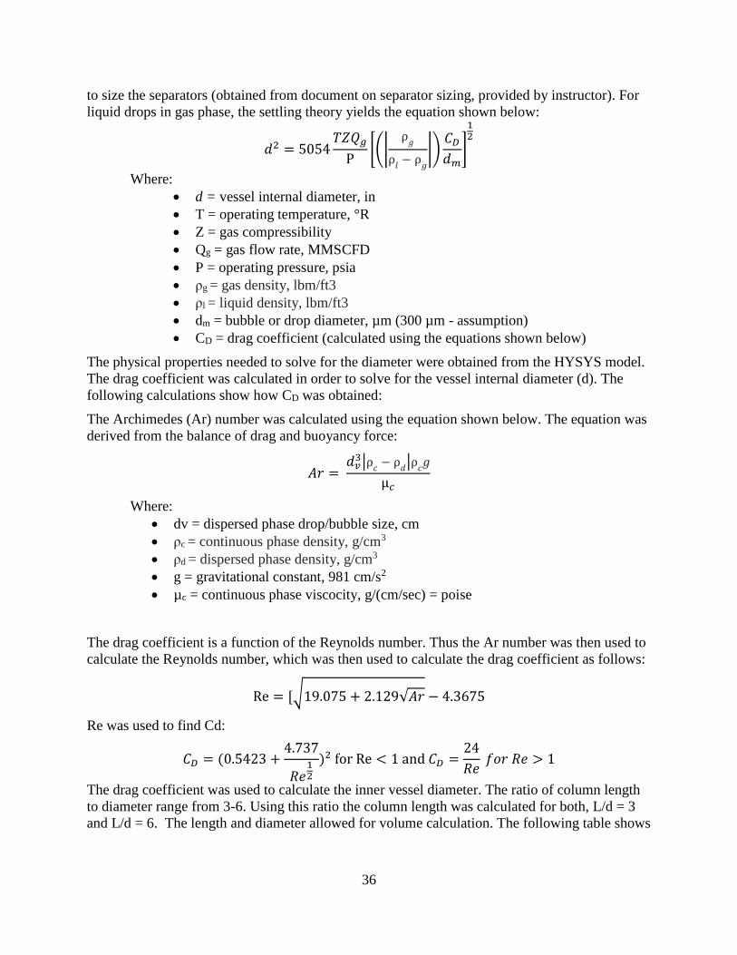
36
to size the separators (obtained from document on separator sizing, provided by instructor). For
liquid drops in gas phase, the settling theory yields the equation shown below:
𝑑2 = 5054𝑇𝑍𝑄𝑔
P[(|
ρ𝑔
ρ𝑙
− ρ𝑔
|)𝐶𝐷
𝑑𝑚]
12
Where:
• d = vessel internal diameter, in
• T = operating temperature, °R
• Z = gas compressibility
• Qg = gas flow rate, MMSCFD
• P = operating pressure, psia
• ρg = gas density, lbm/ft3
• ρl = liquid density, lbm/ft3
• dm = bubble or drop diameter, µm (300 µm - assumption)
• CD = drag coefficient (calculated using the equations shown below)
The physical properties needed to solve for the diameter were obtained from the HYSYS model.
The drag coefficient was calculated in order to solve for the vessel internal diameter (d). The
following calculations show how CD was obtained:
The Archimedes (Ar) number was calculated using the equation shown below. The equation was
derived from the balance of drag and buoyancy force:
𝐴𝑟 = 𝑑𝑣
3|ρ𝑐
− ρ𝑑|ρ
𝑐𝑔
µ𝑐
Where:
• dv = dispersed phase drop/bubble size, cm
• ρc = continuous phase density, g/cm3
• ρd = dispersed phase density, g/cm3
• g = gravitational constant, 981 cm/s2
• µc = continuous phase viscocity, g/(cm/sec) = poise
The drag coefficient is a function of the Reynolds number. Thus the Ar number was then used to
calculate the Reynolds number, which was then used to calculate the drag coefficient as follows:
Re = [√19.075 + 2.129√𝐴𝑟 − 4.3675
Re was used to find Cd:
𝐶𝐷 = (0.5423 +4.737
𝑅𝑒12
)2 for Re < 1 and 𝐶𝐷 =24
𝑅𝑒 𝑓𝑜𝑟 𝑅𝑒 > 1
The drag coefficient was used to calculate the inner vessel diameter. The ratio of column length
to diameter range from 3-6. Using this ratio the column length was calculated for both, L/d = 3
and L/d = 6. The length and diameter allowed for volume calculation. The following table shows
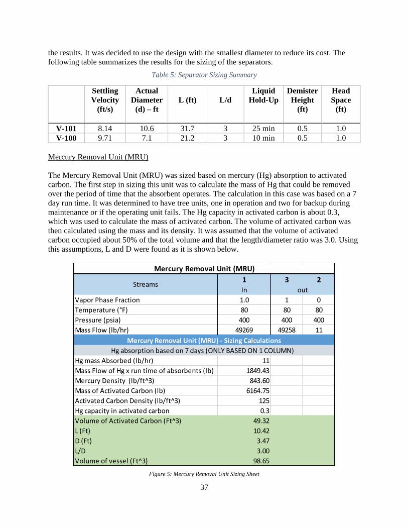
37
the results. It was decided to use the design with the smallest diameter to reduce its cost. The
following table summarizes the results for the sizing of the separators.
Table 5: Separator Sizing Summary
Settling
Velocity
(ft/s)
Actual
Diameter
(d) – ft
L (ft)
L/d
Liquid
Hold-Up
Demister
Height
(ft)
Head
Space
(ft)
V-101 8.14 10.6 31.7 3 25 min 0.5 1.0
V-100 9.71 7.1 21.2 3 10 min 0.5 1.0
Mercury Removal Unit (MRU)
The Mercury Removal Unit (MRU) was sized based on mercury (Hg) absorption to activated
carbon. The first step in sizing this unit was to calculate the mass of Hg that could be removed
over the period of time that the absorbent operates. The calculation in this case was based on a 7
day run time. It was determined to have tree units, one in operation and two for backup during
maintenance or if the operating unit fails. The Hg capacity in activated carbon is about 0.3,
which was used to calculate the mass of activated carbon. The volume of activated carbon was
then calculated using the mass and its density. It was assumed that the volume of activated
carbon occupied about 50% of the total volume and that the length/diameter ratio was 3.0. Using
this assumptions, L and D were found as it is shown below.
Figure 5: Mercury Removal Unit Sizing Sheet
1 3 2In
Vapor Phase Fraction 1.0 1 0
Temperature (°F) 80 80 80
Pressure (psia) 400 400 400
Mass Flow (lb/hr) 49269 49258 11
Hg mass Absorbed (lb/hr) 11
Mass Flow of Hg x run time of absorbents (lb) 1849.43
Mercury Density (lb/ft^3) 843.60
Mass of Activated Carbon (lb) 6164.75
Activated Carbon Density (lb/ft^3) 125
Hg capacity in activated carbon 0.3
Volume of Activated Carbon (Ft^3) 49.32
L (Ft) 10.42
D (Ft) 3.47
L/D 3.00
Volume of vessel (Ft^3) 98.65
Mercury Removal Unit (MRU)
outStreams
Mercury Removal Unit (MRU) - Sizing Calculations
Hg absorption based on 7 days (ONLY BASED ON 1 COLUMN)

38
Amine Treatment Unit (ATU)
The amine treatment unit was designed as a one-pass MDEA system where most of the H2S and
some CO2 is removed. In this unit, the MDEA can be regenerated but it was determined that this
could be considered outer battery limit (OBL). In the ATU, regeneration was not taken into
account. The sulfur content in the inlet stream (stream 3) was determined using the gas flow and
% of H2S. The gas velocity can be used to find the cross sectional area of the column and thus
the diameter. The equation used to calculate the gas velocity is shown below:
𝑉𝑔𝑎𝑠 = 0.25 ∗ [(𝜌𝑀𝐷𝐸𝐴 − 𝜌𝑔𝑎𝑠)/𝜌𝑔𝑎𝑠]12
An assumption of length to diameter of 6 was assumed in order to calculate the length and
volume of the column unit. The table below shows a summary of the results:
Figure 6: Amine Treatment Tower Sizing Sheet
Heat Exchangers
The sizing of these components was governed by the desired temperatures of the process stream,
and the utility chosen. The types of utilities chosen were cooling water, other process streams, fuel,
and refrigerant. The most cost efficient method is utilizing the process streams, because this is free
energy that is being used. All of the heat exchangers in the system are either countercurrent shell
and tube, a fired heater, or a refrigeration unit. The first step in sizing a shell and tube heat
exchanger is to determine the process stream temperature desired and the utility you are going to
use. The following equations are the governing equations for sizing the heat exchangers. The duty,
Q, is calculated from the change of temperatures of the process stream.
𝑄 = 𝑚 𝐶𝑝,𝑎𝑣𝑔 ∆𝑇
Streams
3 4 6
Vapor Phase Fraction 1.0 0.0 1.0
Temperature (F) 80 40 72
Pressure (psia) 400 400 400
Mass Flow (lb/hr) 49258 124245 47855
Gas Flow (MMSCFD) 24.95 Sulfur Content 31557.31 lb S/day
Actual Gas Flow 618.5 CFM Circulation rate, MDEA 93.56 gpm
10.31 ft^3/s Gas Velocity 11.50 ft/s
% H2S in feed stream 1.5 L/D = 6 6
% CO2 in feed stream 1.5 Inner Diameter (D) 1.19 ft
Temperature 80 F Length (L) 7.15 ft
Pressure 385.3 psig Volume 7.98 ft^3
K (MMSCFD) 1.25 Retention Time 10 minutes
Gas Density 1.328 lbm/ft3
MDEA Density 62.428 lbm/ft3
Amine Treatment Unit (ATU)
Properties Sizing and Calculations
In Out
5
0.0
52
400
125648

39
Where,
m = mass flow rate of utility, lb/hr
Cp, avg = average heat capacity of the inlet and outlet process streams, BTU/lb-F
∆T = change in process stream temperature, F
With the duty needed, the area of the heat exchanger can be determined by rearranging the
following equation.
𝑄 = 𝑈𝐴 ∆𝑇𝐿𝑀
Where,
U = heat transfer coefficient, BTU/F –ft2
∆TLM = the log mean temperature difference
∆𝑇𝐿𝑀 = ∆𝑇𝐴 − ∆𝑇𝐵
𝐿𝑛(∆𝑇𝐴
∆𝑇𝐵)
Where, ∆TA is the largest temperature difference between the two ends of the heat
exchanger.
𝐴 =𝑄
𝑈 ∆𝑇𝐿𝑀∗ 𝜎
where, σ is a multiplicative safety factor, σ = 1.15
The following equations illustrate the sizing for E -108, as an example calculation.
𝑇𝑖𝑛,𝑝𝑟𝑜𝑐𝑒𝑠𝑠 = 280 𝐹, 𝑇𝑜𝑢𝑡,𝑝𝑟𝑜𝑐𝑒𝑠𝑠 = 160 𝐹
𝑇𝑖𝑛,𝑢𝑡𝑖𝑙𝑖𝑡𝑦 = 90 𝐹, 𝑇𝑜𝑢𝑡,𝑢𝑡𝑖𝑙𝑖𝑡𝑦 = 110 𝐹
𝑈 = 50, 𝜎 = 1.15
𝑄 = 597840 (𝑙𝑏
ℎ𝑟) (
0.5109 + 0.92866
2
𝐵𝑇𝑈
𝑙𝑏 − 𝐹) ∗ (280 − 160)𝐹 = 32.684 𝑀𝑀𝐵𝑇𝑈
∆𝑇𝐿𝑀 = (280 − 110) − (160 − 90)
𝐿𝑛 ((280 − 110)
160 − 90 ) = 113 𝐹
𝐴 = (32.684 𝑀𝑀𝐵𝑇𝑈
50 (𝐵𝑇𝑈
𝐹 − 𝑓𝑡2 −) ∗ 113𝐹 ∗ 106) ∗ 1.15 = 6670 𝑓𝑡2

40
Table 5: Summary of Heat Exchanger Sizes
Equipment
name
Process in
(F)
Process out
(F)
Utility Type Utility in
(F)
Utility out
(F)
Area
(ft2)
E -100 72 500 Process 1100 1063 748
E -107 216 520 Process 1063 636 14077
E -101 636 280 CW 90 110 7757
E -108 280 160 CW 90 110 6670
E -103 695 280 CW 90 110 2564
E -102 30 206 Process 892 607 1003
E -105 607 500 CW 90 110 516
E-109 172 120 CW 90 110 1181
The fired heater is fueled by using a process waste stream. This contains methane, which can be
burned to produce enough heat to get the process stream of interest to the desired temperature. The
following equation was used to determine the area needed for the fired heater.
𝑄 = 𝐹𝜎𝛼𝐴𝑐(𝑇𝑡4 − 𝑇𝑔
4)
Where,
F = 0.702, is the exchange factor of the heater, (from Perry’s handbook.)
σ = 1.71 E-9 (BTU/(hr-ft2-R4), a given value.
α = 60%, efficiency of the combustion
Q = Duty, BTU/hr
TT = temperature of the wall of the fired heater, R
Tg = temperature of the gas exhaust, R.
The following calculation represents the sizing for the fired heater.
𝑇𝑡 = 2660 𝑅, 𝑇𝑔 = 1760 𝑅, 𝑄 = 183𝑀𝑀𝐵𝑇𝑈
𝐻𝑅
𝐴𝑐 =183
0.702(0.60) ∗ (1.71𝐸 − 9) ∗ 106 ∗ (26604 − 17604)= 6275 𝑓𝑡2
𝐴 = 1.1 ∗ 6275 𝑓𝑡2 = 6903 𝑓𝑡2

41
Table 6: Summary of Fired Heater Size
Equipment
name
Process in
(F)
Process out
(F)
Utility
Type
Utility in
(F)
Utility out
(F)
Area
(ft2)
FH -100 520 1100 Process 30 1300 6903
The final process temperature control system is the refrigeration unit. The overall refrigeration unit
is an OBL process, but the cost must be approximated and the heat exchange unit must be sized.
The following figure was used to determine the overall cost of the refrigeration. Propane was
chosen as the refrigerant due to the temperature desired. 70 MMBTU is required for this system,
according to the Bluebook. Here, the yellow dot signifies where our refrigeration unit will be
operating.
Table 7: Summary of Refrigeration Unit Cost
Equipment
name
Process
in (F)
Process
out (F)
Utility
Type
Utility
in
(F)
Utility
out (F)
Area
(ft2)
Duty
(MMBTU/
hr)
Cost
($/MMBTU)
E -104 197.2 30 Refrig. -44 -44 4557 70 35
0
10
20
30
40
50
60
70
80
90
100
-150 -100 -50 0 50 100
Cost of
Refr
ig,
$/M
MB
TU
Temperature, F
Refrigeration Cost
Total Cost
Figure 7: Refrigeration Cost

42
Compressors, Expanders, and Pumps
The sizing of the compressors and expanders was governed by the stream flow rates and
required changes in pressure. It is important to size compressors and expanders for the correct
anticipated load as they are an important part of the energy balance within the process.
Compressors are very energy intensive and should be sized properly to avoid wasted input.
Expanders have the potential to capture energy and should be sized properly to ensure capture of
energy for reuse and ability to handle the stream. Both compressors and expanders must be sized
large enough to handle the stream, yet as small as possible so as not to incur extra cost.
The governing equations for sizing these units are as follows:
𝑍𝑎𝑣𝑔 =𝑍1+𝑍2
2 (1)
𝑇2
𝑇1= (
𝑃2
𝑃1)
𝑛−1
𝑛 (2)
𝑛−1
𝑛=
(𝑘−1)
(𝑘∗𝜂𝑝) (3)
𝑘 =𝑐𝑝
𝑐𝑣 (4)
𝐻𝑃 =𝑛
(𝑛−1)∗
𝑍𝑎𝑣𝑔∗𝑅∗𝑇1
𝑀𝑊∗ ((
𝑃2
𝑃1)
(𝑛−1)
𝑛− 1) (5)
𝐵𝐻𝑃 = 𝑤∗𝐻𝑃
33,000∗ 𝜂𝑝 (6)
Values for the variables in these equations were drawn from the HYSYS model.
For compressor K-104, an example calculation can be found below:
𝑍𝑎𝑣𝑔 =1.000+1.002
2= 1.0001 (1)
𝑇2 = 619.67 ∗ (180
30)
.337472
= 1155.16 𝑅 (2)
𝑛−1
𝑛=
(1.368−1)
(1.368∗0.79712)= .3476 (3)
𝑘 =𝑐𝑝
𝑐𝑣 = 1.385 (4)
𝐻𝑃 =1
.3476∗
1.0001∗1545.4∗619.67
11.76∗ ((
180
30)
0.3476
− 1) = 222933.1 (5)
𝑃𝑜𝑤𝑒𝑟 = 2231.52∗222933.1
33,000∗ 0.79972= 18850.52 𝐵𝐻𝑃 (6)
Using these calculations for each compressor and expander followed by unit conversions, a final
power usage in units of kW was determined. The compressor names, pressures, and power usages
can be found in the table below. The expander names, pressures, and power outputs can also be
found in the table below.

43
Table 8: Expander and Compressor Summary:
Unit P1 (psia) P2 (psia) Power (kW)
K-100 (exp) 400 30 -13837.7
K-102 (exp) 1015 30 -13217.8
K-104 30 180 14056.84
K-105 180 1015 16111.87
The sizing of the pumps was governed mainly by the flowrate and density of the fluid traveling
through the pump. The NPSH and efficiency were determined by using the design flow in
combination with the two following charts from the Blue Book and several equations. Pumps are
relatively inexpensive, so backups were easily purchased for each of the pumps in the process. It
is crucial that pumps are sized largely enough to handle the large flowrate of the process.
Figure 8: NPSH determination chart for pump sizing (P-100 shown)

44
Figure 9: Efficiency determination chart for pump sizing (P-100 shown)
The equations for sizing the pumps include the following:
𝐷𝑒𝑠𝑖𝑔𝑛 𝐹𝑙𝑜𝑤 = 𝑃𝑟𝑜𝑐𝑒𝑠𝑠 𝐹𝑙𝑜𝑤 ∗ 1.25 (1)
𝑃𝑠𝑐𝑡𝑛 = 𝑃𝑠𝑜𝑢𝑟𝑐𝑒 +𝑁𝑃𝑆𝐻∗𝜌
144𝑖𝑛2
𝑓𝑡2
− ∆𝑃𝑠𝑐𝑡𝑛 𝑙𝑖𝑛𝑒 − ∆𝑃𝑒𝑛𝑡𝑟𝑎𝑛𝑐𝑒,𝑒𝑥𝑖𝑡 𝑙𝑜𝑠𝑠𝑒𝑠 (2)
𝑃𝑑𝑠𝑐ℎ = 𝑃𝑑𝑒𝑠𝑡𝑖𝑛𝑎𝑡𝑖𝑜𝑛 +𝐻𝑑𝑠𝑐ℎ∗𝜌
144𝑖𝑛2
𝑓𝑡2
+ ∆𝑃𝐻𝑋 + ∆𝑃𝐹𝐸 + ∆𝑃𝐶𝑉 + ∆𝑃𝐿𝑖𝑛𝑒 + ∆𝑃𝑒𝑛𝑡𝑟𝑎𝑛𝑐𝑒,𝑒𝑥𝑖𝑡 𝑙𝑜𝑠𝑠𝑒𝑠 (3)
𝐻𝑒𝑎𝑑 (𝑓𝑡) = (𝑃2 − 𝑃1)𝑝𝑠𝑖𝑎 ∗ 144𝑖𝑛2
𝑓𝑡2 ∗ 𝜌𝑓𝑡3
𝑙𝑏𝑚 (4)
𝐵𝐻𝑃 = 𝑤∗𝐻𝑃
33,000∗ 𝜂𝑝 (5)

45
𝑀𝐻𝑃 =𝐵𝐻𝑃
𝜂𝑝 (6)
An example calculation for pump P-100 can be found below.
272.63 𝐺𝑃𝑀 = 218.10 𝐺𝑃𝑀 ∗ 1.25 (1)
31.5 𝑝𝑠𝑖𝑎 = 29 𝑝𝑠𝑖𝑎 +8.5∗59.7
144𝑖𝑛2
𝑓𝑡2
− 1 𝑝𝑠𝑖𝑎 − 0 𝑝𝑠𝑖𝑎 (2)
79.14 𝑝𝑠𝑖𝑎 = 50 +10∗59.7
144𝑖𝑛2
𝑓𝑡2
+ 0 𝑝𝑠𝑖𝑎 + 3 𝑝𝑠𝑖𝑎 + 10 𝑝𝑠𝑖𝑎 + 12 𝑝𝑠𝑖𝑎 + 0 𝑝𝑠𝑖𝑎 (3)
114.87 𝑓𝑡 = (79.14 − 31.5)𝑝𝑠𝑖𝑎 ∗ 144𝑖𝑛2
𝑓𝑡2∗ 59.7
𝑓𝑡3
𝑙𝑏𝑚 (4)
11.47 = 2175.79∗114.87
33,000∗ 0.66 (5)
12.75 =11.47
0.9 (6)
Using these equations, taking care to balance the pressure on either side of the pump, these
pieces of equipment can be properly sized for the process. The pumps will maintain appropriate
pressure of streams as they exit the distillation towers and move on to product storage or waste
water treatment.
Distillation Towers
In order to carry out the separation required to obtain the maximum methanol product purity, the
design modeled by HYSYS consisted of two identical distillation columns. The feed entering
each distillation column is identical in composition and flow rate. As a result, the product leaving
each distillation column is also identical in composition and flow rate. The distillation columns
separate the methanol product from water. The purity attained is 99.89 % pure methanol with a
flow rate of approximately 37,000 lbm/hr per distillation column. The distillation columns have
40 trays each in addition to a condenser and a reboiler bringing the total number of stages to 42
theoretical stages per distillation column.
The temperature of the feed was chosen to be equal to the temperature of the feed tray in the
distillation column. This was done to limit the flooding of the distillation column. As for the
pressure selection, the pressure of the feed was selected to be 15 psig in order to reduce the
chance of a back pressurization occurring within the column during startup. Initially, the design
only consisted of one distillation column. However, this design failed for several reasons.
Economically, to achieve the necessary separation would require approximately 100 plates. As a
result, the distillation column would not follow the design specifications. Additionally, the vapor
flow rate was too great which did not permit us to use the Glitsch method to estimate the
required diameters for the single-pass, double-pass, and four-pass systems. Another issue that
was encountered with this design was the very high reflux ratio. A high reflux ratio requires
greater energy and size of the overall column; thus, increasing the cost of the column. We elected
to split the feed into two identical distillation columns in order to reduce the flow rate and the
reflux ratio. Based on the design parameters, we were able to achieve a reflux ratio of 4.1. As a
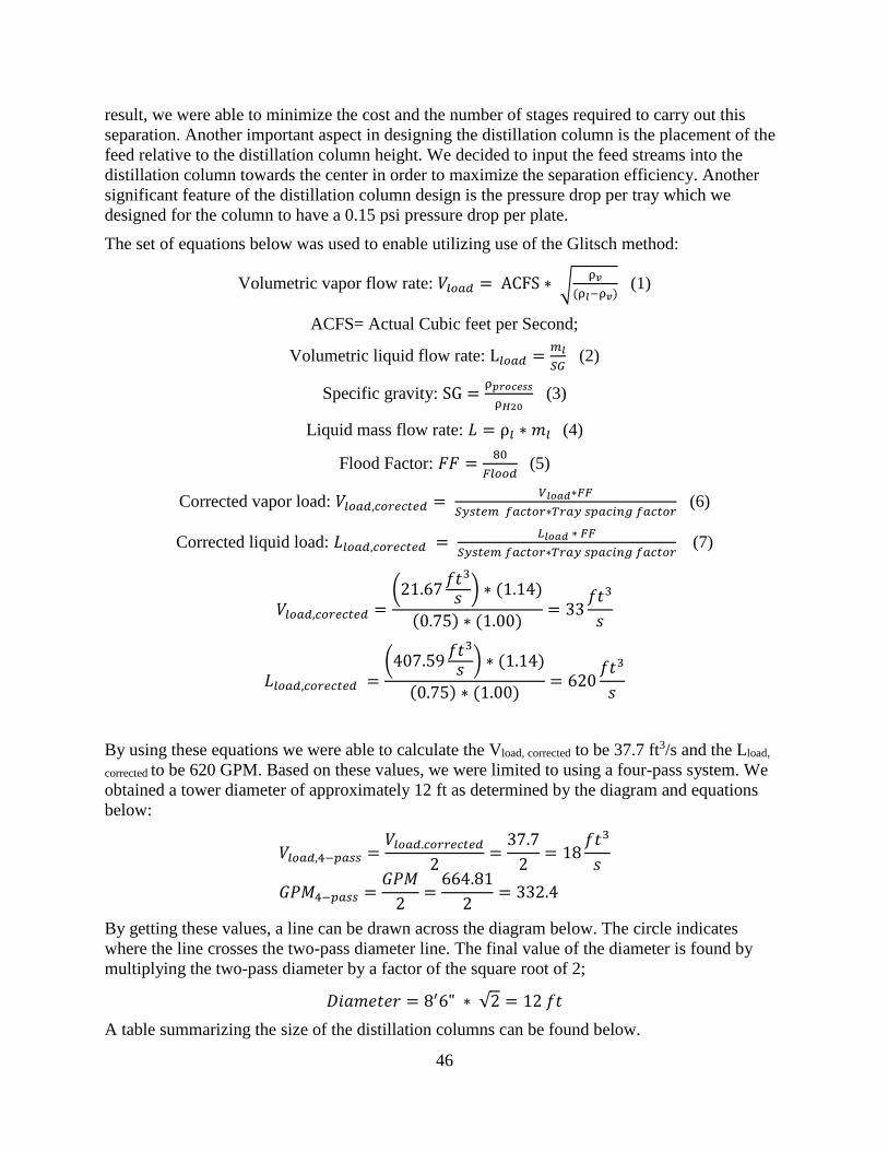
46
result, we were able to minimize the cost and the number of stages required to carry out this
separation. Another important aspect in designing the distillation column is the placement of the
feed relative to the distillation column height. We decided to input the feed streams into the
distillation column towards the center in order to maximize the separation efficiency. Another
significant feature of the distillation column design is the pressure drop per tray which we
designed for the column to have a 0.15 psi pressure drop per plate.
The set of equations below was used to enable utilizing use of the Glitsch method:
Volumetric vapor flow rate: 𝑉𝑙𝑜𝑎𝑑 = ACFS ∗ √ρ𝑣
(ρ𝑙−ρ𝑣) (1)
ACFS= Actual Cubic feet per Second;
Volumetric liquid flow rate: L𝑙𝑜𝑎𝑑 =𝑚𝑙
𝑆𝐺 (2)
Specific gravity: SG =ρ𝑝𝑟𝑜𝑐𝑒𝑠𝑠
ρ𝐻20 (3)
Liquid mass flow rate: 𝐿 = ρ𝑙 ∗ 𝑚𝑙 (4)
Flood Factor: 𝐹𝐹 =80
𝐹𝑙𝑜𝑜𝑑 (5)
Corrected vapor load: 𝑉𝑙𝑜𝑎𝑑,𝑐𝑜𝑟𝑒𝑐𝑡𝑒𝑑 = 𝑉𝑙𝑜𝑎𝑑∗𝐹𝐹
𝑆𝑦𝑠𝑡𝑒𝑚 𝑓𝑎𝑐𝑡𝑜𝑟∗𝑇𝑟𝑎𝑦 𝑠𝑝𝑎𝑐𝑖𝑛𝑔 𝑓𝑎𝑐𝑡𝑜𝑟 (6)
Corrected liquid load: 𝐿𝑙𝑜𝑎𝑑,𝑐𝑜𝑟𝑒𝑐𝑡𝑒𝑑 = 𝐿𝑙𝑜𝑎𝑑 ∗ 𝐹𝐹
𝑆𝑦𝑠𝑡𝑒𝑚 𝑓𝑎𝑐𝑡𝑜𝑟∗𝑇𝑟𝑎𝑦 𝑠𝑝𝑎𝑐𝑖𝑛𝑔 𝑓𝑎𝑐𝑡𝑜𝑟 (7)
𝑉𝑙𝑜𝑎𝑑,𝑐𝑜𝑟𝑒𝑐𝑡𝑒𝑑 =(21.67
𝑓𝑡3
𝑠 ) ∗ (1.14)
(0.75) ∗ (1.00)= 33
𝑓𝑡3
𝑠
𝐿𝑙𝑜𝑎𝑑,𝑐𝑜𝑟𝑒𝑐𝑡𝑒𝑑 =(407.59
𝑓𝑡3
𝑠 ) ∗ (1.14)
(0.75) ∗ (1.00)= 620
𝑓𝑡3
𝑠
By using these equations we were able to calculate the Vload, corrected to be 37.7 ft3/s and the Lload,
corrected to be 620 GPM. Based on these values, we were limited to using a four-pass system. We
obtained a tower diameter of approximately 12 ft as determined by the diagram and equations
below:
𝑉𝑙𝑜𝑎𝑑,4−𝑝𝑎𝑠𝑠 =𝑉𝑙𝑜𝑎𝑑.𝑐𝑜𝑟𝑟𝑒𝑐𝑡𝑒𝑑
2=
37.7
2= 18
𝑓𝑡3
𝑠
𝐺𝑃𝑀4−𝑝𝑎𝑠𝑠 =𝐺𝑃𝑀
2=
664.81
2= 332.4
By getting these values, a line can be drawn across the diagram below. The circle indicates
where the line crosses the two-pass diameter line. The final value of the diameter is found by
multiplying the two-pass diameter by a factor of the square root of 2;
𝐷𝑖𝑎𝑚𝑒𝑡𝑒𝑟 = 8′6" ∗ √2 = 12 𝑓𝑡
A table summarizing the size of the distillation columns can be found below.

47
Figure 10. Glitsch Method diagram

48
Table 9: Summarization of Distillation Tower Sizes
Specification Value
Column Diameter (ft) 12
Total Column Height (ft) 141
Reflux Drum Height (ft) 9
Pressure (Top/Btm), psia 24.5/29
Temperature (Top/Btm), ºF 175/228
Number of
Theoretical/Actual Stages
40/71
Reflux Drum Diameter (ft) 3
Reboiler Height (ft) 15
Reboiler Diameter (ft) 5.5
Theoretical Stages 42
Actual Trays 71
Condenser Duty
(MMBTU/hr) 16.6
Reboiler Duty
(MMBTU/hr) 46.2
Reflux Ratio 4.1
Feed Tray Location 28 (theoretical)

49
Utility Balance
The utility balance was constructed to display the yearly costs of each of the plants utility services.
This table shows the MMBtu/hr usage of utilities like steam and cooling water of various pressures
and sources respectively. For the fired heater, the needed energy is obtained from utilizing a waste
gas stream containing methane and hydrogen. This stream is split and also used to heat the
Reformer. However, more energy is required and the remaining energy needed is from purchased
fuel. The overall cost of the Refrigeration unit was estimated from Figure 1. The total cost to
operate the unit is approximately $32 per MMBTU/hr. The overall yearly cost sums to 28.99
MM$/yr. The main cost of this is from the fuel needed for the fired heater. Below is a summary of
the total costs, and the following page includes a summary of the utilities needed for each unit.
Table 9: Summary of Overall Costs for Utilities
Utility Total Cost (MM$/yr)
Fuel Gas 3.93
MPS 1.77
CW 0.69
Refrigeration 18.82
Power 3.78
Total 28.99

50
Figure 11: Microsoft Excel Spreadsheet for the Overall Utilities needed for the plant per unit.
kw
System Fuel Gas MPS CW Refrig Power3 Comments
Temperature, F 388 90--->110 -441
Pressure, psia 200 70 63
MRU
ATU
E-100 process
E-107 process
E-101 111.0
E-103 39.2
E-108 32.7
E-102 process
E-105 10.0
E-104 70.0 Refrigeration
E-109 4.3
Fire Heater (FH-100) Waste Stream as fuel
MIX-100
MIX-101
MIX-102
TEE-100 process (waste stream)
Expander: K-100 -9686.4 Power Generated
Compressor: K-104 14056.8
Compressor: K-105 16111.9
Expander: K-102 -9252.5 Power Generated
Pump: P-100 8.6
Pump: P-101 17.3
burn CH4
Prereformer 0.3 Exothermic
Steam Reformer 55 Endothermic
MeOH Synth 93.80 Exothermic
T-100 19 19.33
T-103 19 19.33
Total, MMBTU/hr 55 38 330 70 11256
Cost, $/MMBTU 2 8.50 5.50 0.25 32.00 0.04
Total Cost, MM$/yr 3.93 1.77 0.69 18.82 3.78
28.99
MMBTU/hr
Utility Balances
Total Utilities Cost, MM$/yr

51
Outside Battery Limits
Estimates were provided for the cost of site development, fuel utility storage, product storage, and
waste water treatment.
With a pilot plant on site, the site must be upgraded and developed to withhold all of the new
equipment and necessary utilities. Therefore, an OBL cost for site development must be
considered. Due to this pilot plant already being installed on the site, it was assumed that they were
using process water for their processes already. To obtain process water for things such as heat
exchangers, a DI water system would need to be on site to reduce the salt deposit formations when
creating the steam. However, due to the increasing the size of the operation, the size of the system
would need to be increased as well. This is a factor in site development.
An estimate was provided for the product storage. The Storage Tank Farm is located 1-mile away
from the plant. There is a 1.5 psi pressure drop across 100 ft of the line. Therefore, the product
must be pumped to approximately 85 psig to reach the tanks at atmospheric pressure. The product
streams must also be cooled to 120 °F, so the vapor pressure isn’t too high for the storage tank.
The estimation was given at capacity of 70000 lb/hr of methanol, where our capacity is
approximately 79100 lb/hr. Therefore, the estimate needed to be scaled both for our fiscal year and
for the capacity of our product. This value is shown in the following capital cost estimate. The
utilities followed this trend as well. Costs were provided for the OBL estimates, and these values
were sized for our necessary capacity and fiscal year. It is assumed that there is already a bio-
treatment area installed on the site for waste water. However, this value needs to be scaled as well,
to our capacity. The bio-treatment area for waste water requires at least a pressure of 50 psia.
Therefore, that is why a pump is installed after the distillation columns. The above mentioned
values are summarized in the capital cost estimation below.

52
Economic Analysis
Capital Estimate
Utilizing the Aspen Process Economic Analyzer (PEA), the cost of all the equipment were able to
be determined for our base case. The costs of the equipment were found using the sizes calculated
and the known variables for each unit. The cost for each unit was taken to be the “Total installed
and manpower cost” from the PEA software. Once all the estimates were determined, the
equipment capital cost for the plant was calculated to be approximately
34.026 MM$. The most expensive pieces of equipment were the compressors/expanders. These
are necessary in our process to meet the proper operating conditions of our process. An itemized
list of all the equipment is found in the appendix.
Table 10: Cost of Equipment
Unit Cost ($MM)
Reactors/Towers 4.218
Heat Exchangers 9.070
Compressors/Expanders/Pumps 19.200
Separators 1.539
Total 34.026
Additional capital costs would need to be factored into the calculation to determine the total capital
cost of the plant. The additional costs that need to be considered include outside battery limit items,
team costs, preoperational and start-up costs, and initial costs of catalysts. Because this is a new
plant, site development, product/raw material storage, and waste water treatment operations need
to be considered for OBL costs. An OBL bid summary for the necessary items was obtained. These
bids need to be scaled to the required capacity and escalated to 2017 dollar values. This was done
using an annual escalation rate of 3%, and a capital estimate exponent of 0.65. A sample
calculation of this is shown below. The total cost of these OBL estimates was approximately
63,620 M$.
𝑀𝑒𝑂𝐻 𝑃𝑟𝑜𝑑𝑢𝑐𝑡 𝑆𝑡𝑜𝑟𝑎𝑔𝑒 𝑆𝑐𝑎𝑙𝑖𝑛𝑔:
𝑂𝑟𝑖𝑔𝑖𝑛𝑎𝑙 𝑏𝑖𝑑: 𝐶𝑜𝑠𝑡1 = 16000 𝑀$, 𝑦𝑒𝑎𝑟 = 2011, 𝐶𝑎𝑝𝑎𝑐𝑖𝑡𝑦1 = 70,000𝑙𝑏
ℎ𝑟
𝑆𝑐𝑎𝑙𝑒𝑑 𝑏𝑖𝑑: 𝐶𝑜𝑠𝑡2 = 𝐶𝑜𝑠𝑡1 ∗ (𝐶𝑎𝑝𝑎𝑐𝑖𝑡𝑦2
𝐶𝑎𝑝𝑎𝑐𝑖𝑡𝑦1)
0.65
∗ 𝐹𝑡𝑖𝑚𝑒 ∗ 𝐹𝑙𝑜𝑐𝑎𝑡𝑖𝑜𝑛
Where,
𝐹𝑡𝑖𝑚𝑒 = (1 + 3%)∆𝑦𝑒𝑎𝑟𝑠
∆𝑦𝑒𝑎𝑟𝑠 = 2017 − 2011 = 6 𝑦𝑒𝑎𝑟𝑠
𝐹𝑡𝑖𝑚𝑒 = (1 + 3%)6 = 1.19
𝐹𝑙𝑜𝑐𝑎𝑡𝑖𝑜𝑛 = 1.10
𝐶𝑜𝑠𝑡2 = 16000 ∗ (79100
70000)
0.65
∗ 1.19 ∗ 1.10 = 22.753 𝑀$
The following table shows the scaled values for the OBL bid summary.

53
Table 11: Summarization Scaled OBL Costs
OBL Item Bid Year Initial Bid
M$
Initial
Capacity Ftime
Our
Capacity
Scaled
Cost (M$)
Site
Development 2015 12000 - 1.0609 - 14004
NG Fuel
Utilities 2013 19500
3000
lbmol/hr 1.1255
524
lbmol/hr 7766
Product Storage 2011 16000 70000 lb/hr 1.1941 79100 lb/hr 22753
Environmental 2010 8000 45000 lb/hr 1.2299 103500
lb/hr 18598
Due to all the reactors being packed with catalyst, initially charging the reactors contributes to
overall capital costs of the plant. The amount of catalyst needed for each reactor is calculated when
sizing the reactors. The mass of catalyst is found by utilizing the volume of catalyst needed and
the catalyst density. The price of the catalyst per pound was provided in the project. The following
table summarizes the catalyst capital costs.
Table 12: Summarization of the Catalyst Capital Costs.
Catalyst
Cost of
Catalyst
($/lb)
Volume of
catalyst
needed (ft3)
Catalyst
Density
(lb/ft3)
Mass of
Catalyst (lb)
Total Cost
(M$)
54-7 Q $6.71 3102 53 164,406 1,100
51-7 $16.19 78 6.81 509 8.2
The other costs related to the team, other miscellaneous costs, and pre-operation and start-up. Team
costs are approximated to be 8% of the total contractor costs (TCC), miscellaneous costs are
approximated to be 4% of the TCC, and the pre-op and S/U are approximated to be 7% of the
TCC. These values are equivalent to approximately 18060 M$.
The final costs that need to be considered escalation and project contingency. Because this startup
takes longer than 1 year, escalation needs to be taken into account. It will be assumed that there is
a 2% escalation annually for the 3 year startup period. The cost of escalation was found to be
approximately 7,150 M$. The project contingency is estimated to be 20% of the current total plant
cost. This value is equal to 24,800 M$.
The total plant capital cost was found to be 148,800 M$. This information is summarized in the
pie chart and the following Capital Estimation Summary below.

54
Figure 12: Itemized Capital Cost Breakdown for the Total Plant Cost
Table 13: Capital Estimation Summary
Total Plant Cost Breakdown
TCC IBL
TCC OBL
Misc
Escalation
Project
Contingency
Capital Estimate : MeOH Plant
Base Case : 49800 lb/hr NG FeedBasis Rev 0 4/21/17
2017
665 MMlb/yr MeOH Base CaseNortheastern US
TCC, M$
IBL Reactors/Towers 4,218
Heat Exchangers 9,070
Compressors/Pumps 19,200
Separators 1,539
TCC IBL 34,026
OBL Site Development 14,004
Utilities 8,263
Raw Matl/Prod Storage 22,753
Environmental 18,598
TCC OBL 63,617
Total Contractor Cost, M$ 97,644
Team Costs 8% of TCC 7,812
Other Costs 4% of TCC 3,906
PreOp & S/U (of TCC) 7% of TCC 6,347
Reforming Catalyst $6.71 164000 1,100
MeOH Synthesis Catalyst 16.19$ 540 9
Current Point Estimate, M$ 116,817Years Escalation
Escalation 6% 3 2% 7,150
Project Contingency 20% of CPE+Esc 24,793
Total Plant Cost, M$ 148,761
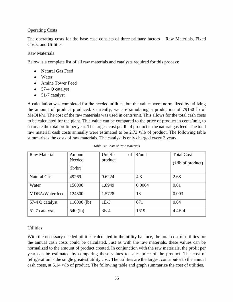
55
Operating Costs
The operating costs for the base case consists of three primary factors – Raw Materials, Fixed
Costs, and Utilities.
Raw Materials
Below is a complete list of all raw materials and catalysts required for this process:
• Natural Gas Feed
• Water
• Amine Tower Feed
• 57-4 Q catalyst
• 51-7 catalyst
A calculation was completed for the needed utilities, but the values were normalized by utilizing
the amount of product produced. Currently, we are simulating a production of 79160 lb of
MeOH/hr. The cost of the raw materials was used in cents/unit. This allows for the total cash costs
to be calculated for the plant. This value can be compared to the price of product in cents/unit, to
estimate the total profit per year. The largest cost per lb of product is the natural gas feed. The total
raw material cash costs annually were estimated to be 2.73 ¢/lb of product. The following table
summarizes the costs of raw materials. The catalyst is only charged every 3 years.
Table 14: Costs of Raw Materials
Raw Material Amount
Needed
(lb/hr)
Unit/lb of
product
¢/unit Total Cost
(¢/lb of product)
Natural Gas 49269 0.6224 4.3 2.68
Water 150000 1.8949 0.0064 0.01
MDEA/Water feed 124500 1.5728 18 0.003
57-4 Q catalyst 110000 (lb) 1E-3 671 0.04
51-7 catalyst 540 (lb) 3E-4 1619 4.4E-4
Utilities
With the necessary needed utilities calculated in the utility balance, the total cost of utilities for
the annual cash costs could be calculated. Just as with the raw materials, these values can be
normalized to the amount of product created. In conjunction with the raw materials, the profit per
year can be estimated by comparing these values to sales price of the product. The cost of
refrigeration is the single greatest utility cost. The utilities are the largest contributor to the annual
cash costs, at 5.14 ¢/lb of product. The following table and graph summarize the cost of utilities.

56
Table 15: Breakdown of Utility Cash Costs.
Utility Amount
Needed
(MMBTU)
Unit/lb of
product
¢/unit Total Cost
(¢/lb of product)
Fuel 55 0.0007 850 0.59
MPS 38 0.0005 550 0.26
Refrigeration 70 0.0009 3200 2.83
Power 11256 (kw) 0.1422 4 0.57
CW 330 0.0042 25 0.10
Waste Water 12446 (gal) 0.16 5 0.78
Figure 13: Annual Cash Costs of Utilities. Refrigeration has the largest impact.
Fixed Costs
The fixed costs included labor, plant overhead, maintenance, property taxes, and insurance. The
labor costs include a yearly salary of $80,000 for 20 plant operators working a total of 4 shifts.
The 20 workers are made up of 1 equipment operator, 1 control room operator, and 2 laborers to
assist with operations per shift. The other 4 workers are made up of maintenance workers and FTE
(full time equivalent) workers. The overhead costs, estimated as 1.5 times the labor cost, the repair
and maintenance was estimated as 1.5% of the TCC, the property tax was estimated as 2.5% of the
Annual Cash Cost of Utilities(¢/lb product)
Fuel
MPS
Refrigeration
Power
CW
Waste Water

57
TCC, and the insurance was estimated as 0.5% of the TCC. The property tax was the greatest
single fixed cost. The total of the fixed costs was estimated to be approximately 1.61 (¢/lb of
product). The following table summarizes these values.
Table 16: Summarization of the Fixed Cash Costs
Fixed Cost ¢/lb of
product
Labor 0.24
Overhead 0.36
Rep. and
Maintenance
0.34
Property Tax 0.56
Insurance 0.11
The following values were summed, to yield a total annual cash cost. This value was equal to 9.47
¢/lb of product, excluding SG&A fees. The greatest single cost in the annual costs were the
utilities. If these could be reduced, the overall wealth of the plant can be increased. The following
figure summarizes the ongoing costs. This value can be used in the economic analysis of the plant,
to determine the overall predict economics of the plant over time.

58
Figure 14: Annual Ongoing Capital Costs (¢/lb product)
Economic Analysis
Basis
The 665 MMlb per year natural gas to methanol plant, which was added to a pilot plant of Nitlion
chemical in Philadelphia, Pennsylvania, costs approximately 149 MM$ over a three-year
construction of the plant. The projected start up is slated for April 2020. The total project lifespan
is 15 years of operation. The annual ongoing cash costs for the plant, including SG&A, are
approximately 9.60 ¢/lb of product. These values were calculated using the costs of utilities and
raw materials at this current time. The price of methanol was defined at 12.5 ¢/lb. Some
assumptions and parameters used in this economic analysis were:
• Yearly Operating Hours = 8400 hours/year
• Project Life = 15 Operating years
• Capital Spending = 15%/35%/50% over the three year building phase.
• Market Build = 25%/70%/100% over the first three operation years.
• Escalation/Inflation = 2% per year.
• Discount Rate = 9%
• Income Tax Rate = 35%
• Working Capital = 10% of revenues.
• SG&A = 1% of sales
Base Case
2.73
4.36
0.78
1.61
Ongoing Costs (¢/lb product)
Raw Materials
Utilities
Waste Water
Fixed Costs

59
The base case economic evaluation for the process of converting a natural gas feed to methanol
was performed using current values of the raw materials and utilities. This was done to give an
accurate estimate based on the startup date of April 2020. The price of methanol was defined at
12.5 ¢/lb. After analysis, it was found that due to depreciation the plant would not get back the
initial capital costs of 149 MM$ over its lifetime.
For the base case, an ATROR, or after tax return on investment, was found to be 7.26 % at the
current product price. This value is approximately half of the target 15%. An analysis of the
cumulative cash flow was performed to see the economics of the plant over time. This is shown in
the figure below.
Figure 15: Cumulative Cash Flow Model for the Life of the Plant
This figure shows that on a yearly basis, the plant will make a profit. However, due to the
depreciation of a dollar over time, the plant does not ever make back the initial capital costs. The
net present worth (NPW) can be defined as how much money would be made for the lifetime of
the plant, scaled to the present value of a dollar. The NPW for the lifetime of the plant was found
to be -13.4 MM$.
Due to the large capital costs and annual operating costs, the plant will not be profitable over its
lifetime. The summary of this economic analysis can be found on the following page.
-200
-150
-100
-50
0
50
100
150
0 5 10 15 20
Cum
mula
tive
Cas
h F
low
(M
M$
)
Years
Cumulative Cash Flow Model
Startup Period
Operating Years

60
Figure 16: Summary of the Economic Analysis
Sensitivity Analyses
An economic evaluation was performed on the plant for operation in Philadelphia, PA from 2017
to 2035. This economic analysis has revealed that the plant will not break even by the end of the
15 operating years. The analysis was performed using cost and inflation data provided by
NitLion Chemicals. To examine the effect of these parameters, several sensitivity analyses were
performed.
MeOH Plant
Base Case Input & Summary Sheet
Capacity, MM lb/yr MeOH 79160 lb/hr 665 Economic Assumptions
Capital, MM$ 149 April 2020 Startup Discount Rate 9%
Income Tax Rate 35%
Working Capital, % of Revenues 10%
Units unit/lb ¢/unit ¢/lb Prod Inflation/Escalation 2%
Raw Materials SG&A, % of Sales 1%
Natural Gas lb 49269 0.6224 4.3 2.68 hours/year 8400
CO2 lb 0 0.0000 1.0 0.00
Water lb 150000 1.8949 0.0064 0.01
Reformer Catalyst lb 110000 0.0001 671.0 0.04
MeOH Catalyst lb 540 0.0000003 1619 0.00
MDEA/Water feed lb 14.8 0.0002 18 0.003
Total Raw Materials 2.73
Utilities
Fuel MMBTU 55 0.0007 850 0.59
Hot Oil MMBTU - 0.0000 - 0.00
HPS MMBTU - 0.0000 - 0.00
MPS MMBTU 38 0.0005 550 0.26
LPS MMBTU - 0.0000 - 0.00
Refrigeration MMBTU 70 0.0009 3200 2.83
Power kw 11256 0.1422 4.00 0.57
CW MMBTU 330 0.0042 25.00 0.10
Waste Water gal 12446 0.16 5 0.78
Total Utilities 5.14
Fixed Costs Workers Shifts
Labor, m/shift 5$80,000/yr/operator 4 80,000.00$ 0.24
Overhead (1.5 x labor) 0.36
Rep & maint. % Capital = 1.5% 0.34
Property tax % Capital = 2.5% 0.56
Insurance % Capital = 0.5% 0.11
Fixed Costs 1.61
TOTAL CASH COSTS 9.47
SG&A 0.13
Return on Capital CFPO, yrs = 7.70 2.90
Required Product Price for 7.3% ATROR 12.50
NPW ($MM) -13.4 ATROR, % 7.26

61
Five sensitivity analyses were performed to investigate the effects of the relevant economic
parameters. Each of the analyses measured the adjustments to the chosen parameter against the
overall ATROR percentage, or discount rate.
The first sensitivity analysis investigates the effects of an increase to initial raw material costs.
The maximum initial cost of raw materials that will yield a non-negative ATROR value is 4.23
c/lb product. The second analysis investigates the effects of changes to initial product price. The
minimum initial product sale price that will yield a non-negative ATROR is 10.99 c/lb product.
The third analysis investigates the effects of changes to the initial utility cost. The maximum
initial utility cost that yields a non-negative ATROR is 6.63 c/lb product. The fourth analysis
investigates the effects of adjustments to the length of the construction schedule of the plant. The
fifth analysis investigates the effect of changing plant capacity. As product capacity was
increased, values for relevant costs were increased with the amount of product. The cost values
were decreased linearly, but increased at a reduced rate. Aside from the parameter(s) adjusted for
each analysis, the other parameters were held constant at the base case values. Plots of these
adjusted parameters versus ATROR percentage can be found below in Figure 15.
Viewing these analyses, it is clear that the plant’s value is closely tied to each of the adjusted
parameters. The economics appear to be able to tolerate roughly the same amount of variation in
terms of increased utility cost, increased raw material cost, and decreased product price before
reaching a negative discount rate. All three of the values affect the economic success of the plant
significantly. The economics could be greatly improved by speeding up construction (without
added cost) or increasing the overall capacity of the plant which will be impossible given the
current natural gas feed. At this point, it would be prudent to research technological advances
that could improves reaction conversions and reduce capital costs in this plant.

62
Figure 17: Sensitivity analyses for varying economic conditions

63
Required Netback
To achieve a target economic performance of 12% After Tax Rate of Return (ATROR) and a
positive net present value (NPV). The price of the product would have to rise 11.26% to 13.92
c/lb product. If it were possible to sell methanol at this price, the plant would be performing very
well given the current specifications, as shown below.
Figure 18: Required Net Back for 12% ATROR
To achieve an economic performance of 0% ATROR or greater, the required netback for the
product is only 10.99 c/lb product. This price of the product would yield a 0% ATROR and a
negative NPV, leaving the process in an unfavorable position, as shown below.
MeOH Plant
Base Case Input & Summary Sheet
Capacity, MM lb/yr MeOH 79160 lb/hr 665 Economic Assumptions
Capital, MM$ 149 April 2020 Startup Discount Rate 9%
Income Tax Rate 35%
Working Capital, % of Revenues 10%
Units unit/lb ¢/unit ¢/lb Prod Inflation/Escalation 2%
Raw Materials SG&A, % of Sales 1%
Natural Gas lb 49269 0.6224 4.3 2.68 hours/year 8400
CO2 lb 0 0.0000 1.0 0.00
Water lb 150000 1.8949 0.0064 0.01
Reformer Catalyst lb 110000 0.0001 671.0 0.04
MeOH Catalyst lb 540 0.0000003 1619 0.00
MDEA/Water feed lb 14.8 0.0002 18 0.003
Total Raw Materials 2.73
Utilities
Fuel MMBTU 55 0.0007 850 0.59
Hot Oil MMBTU - 0.0000 - 0.00
HPS MMBTU - 0.0000 - 0.00
MPS MMBTU 38 0.0005 550 0.26
LPS MMBTU - 0.0000 - 0.00
Refrigeration MMBTU 70 0.0009 3200 2.83
Power kw 11256 0.1422 4.00 0.57
CW MMBTU 330 0.0042 25.00 0.10
Waste Water gal 12446 0.16 5 0.78
Total Utilities 5.14
Fixed Costs Workers Shifts
Labor, m/shift 5$80,000/yr/operator 4 80,000.00$ 0.24
Overhead (1.5 x labor) 0.36
Rep & maint. % Capital = 1.5% 0.34
Property tax % Capital = 2.5% 0.56
Insurance % Capital = 0.5% 0.11
Fixed Costs 1.61
TOTAL CASH COSTS 9.47
SG&A 0.14
Return on Capital CFPO, yrs = 5.19 4.31
Required Product Price for 12.0% ATROR 13.92
NPW ($MM) 26.3 ATROR, % 12.00

64
Figure 19: Required Net Back for 0% ATROR
With the current price of 12.5 c/lb product, the plant maintains a positive ATROR, but a negative
NPV12. The present economic situation would require an increase in product price to achieve
target economic performance and financial viability.
MeOH Plant
Base Case Input & Summary Sheet
Capacity, MM lb/yr MeOH 79160 lb/hr 665 Economic Assumptions
Capital, MM$ 149 April 2020 Startup Discount Rate 9%
Income Tax Rate 35%
Working Capital, % of Revenues 10%
Units unit/lb ¢/unit ¢/lb Prod Inflation/Escalation 2%
Raw Materials SG&A, % of Sales 1%
Natural Gas lb 49269 0.6224 4.3 2.68 hours/year 8400
CO2 lb 0 0.0000 1.0 0.00
Water lb 150000 1.8949 0.0064 0.01
Reformer Catalyst lb 110000 0.0001 671.0 0.04
MeOH Catalyst lb 540 0.0000003 1619 0.00
MDEA/Water feed lb 14.8 0.0002 18 0.003
Total Raw Materials 2.73
Utilities
Fuel MMBTU 55 0.0007 850 0.59
Hot Oil MMBTU - 0.0000 - 0.00
HPS MMBTU - 0.0000 - 0.00
MPS MMBTU 38 0.0005 550 0.26
LPS MMBTU - 0.0000 - 0.00
Refrigeration MMBTU 70 0.0009 3200 2.83
Power kw 11256 0.1422 4.00 0.57
CW MMBTU 330 0.0042 25.00 0.10
Waste Water gal 12446 0.16 5 0.78
Total Utilities 5.14
Fixed Costs Workers Shifts
Labor, m/shift 5$80,000/yr/operator 4 80,000.00$ 0.24
Overhead (1.5 x labor) 0.36
Rep & maint. % Capital = 1.5% 0.34
Property tax % Capital = 2.5% 0.56
Insurance % Capital = 0.5% 0.11
Fixed Costs 1.61
TOTAL CASH COSTS 9.47
SG&A 0.11
Return on Capital CFPO, yrs = 15.89 1.41
Required Product Price for 0.0% ATROR 10.99
NPW ($MM) -55.5 ATROR, % 0.03

65
Alternate Process Studies
Alternate Process Study 1- Changing the Pressure Ratio
This process study entailed changing the pressure ratio of the compressors between the SMR and
MeOH reactors to 2.45. This requires the use of 4 compressors, instead of the 2 previously
determined. One possible benefit of this is decreasing the size and cost of the compressors, due to
decreasing the duty they perform. Also, another possible benefit to this system could be decreasing
the size and amount of heat exchangers needed between compressors. The smaller pressure ratio
causes a smaller temperature increase in the outlet streams of the compressors. It is predicted this
would allow for only 1 heat exchanger to be used during this overall compression. The costs of
this alternate design can be found in needing to purchase and operate 2 additional compressors.
Also, the operating costs of these compressors need to be taken into account. The diagram on the
next page illustrates this process study.
A quantitative analysis was completed on this process study because the largest single unit capital
cost in the system is the compressors. To begin this study, the new capital costs of the compressors
were determined using ASPEN Process Economic Analyzer software. The following table shows
the proposed compressor specifications and their corresponding prices:
Compressor
Name
Inlet T
(°F)
Inlet P
(psia)
Outlet T
(°F)
Outlet P
(psia)
Price
MM$
K-1 160 30 385 73.5 2.39
K-2 385 73.5 693 180 2.33
K-3 280 180 549 441 2.37
K-4 549 441 886 1015 2.35
Total costs for equipment and installation = $ 9.44 MM.
The heat exchanger would be the same size and require the same amount of cooling duty than the
base case exchanger that is part of the compressor system. While the cooling duty is similar, the
capital cost of the equipment has increased significantly from $ 7.71 MM to $ 9.44 MM.
Additionally, the power required to operate the smaller compressors is negligibly less (13900 kW
as compared to 14100 kW) than the base case operating costs. At this rate, it would take 22 years
to recoup the capital cost disparity. However, as these numbers are estimates for power
consumption, capital cost, and power utility cost, a period of roughly 30 years will be assumed.
As the lifetime of our project simulation is fewer than 30 years, this will be an untenable decision.
In combination, these factors lead to an overall increase in cost for this alternative process study.
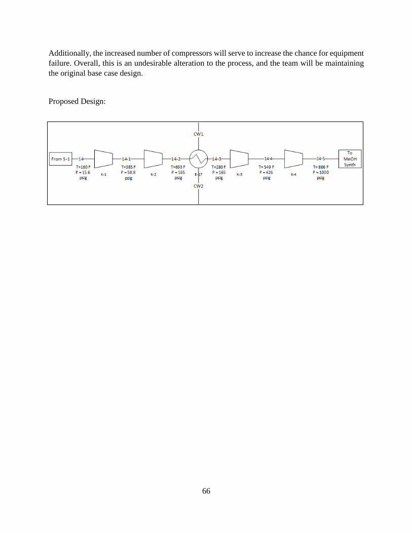
66
Additionally, the increased number of compressors will serve to increase the chance for equipment
failure. Overall, this is an undesirable alteration to the process, and the team will be maintaining
the original base case design.
Proposed Design:

67
Alternate Process Study 2 – Changing to a Three-Phase Separator
This case study entailed removing separator 1, and replacing separator 2 with a three phase
separator. This allows for a large amount of water to be recycled back to the Steam Reformer.
There are many potential benefits for this. One potential benefit is increasing the overall
conversion in the SMR. The more water fed, the more conversion of methane is obtained. This
leads to an increase of methanol product obtained. Another benefit is reducing the number of heat
exchangers and separators needed. By utilizing this design, 3 less heat exchangers and 1 less
separator is needed. This could increase the size of the equipment, increase the flowrate of utility
streams, and increase the duties needed. The attached BFD shows the overall process for this study.
Benefits
• More water can be recycled, increasing the overall efficiency of the SMR.
• Only one Separator needs to be purchased.
Costs
• With more water flowing through the process than the base case, the size of all units will
increase. This may offset the price of not purchasing a second separator.
• Compressor sizes will increase due to more flow going into them. This will increase the
price drastically. Compressors have the greatest effect on the capital cost.
This process was not chosen to be analyzed quantitatively because compressors had the greatest
effect on the IBL capital cost. Therefore, it was more desirable to research a cost saving measure
with these units.

68
Proposed Design:
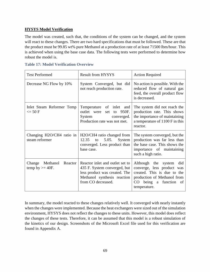
69
HYSYS Model Verification
The model was created, such that, the conditions of the system can be changed, and the system
will react to these changes. There are two hard specifications that must be followed. These are that
the product must be 99.85 wt% pure Methanol at a production rate of at least 71500 lbm/hour. This
is achieved when using the base case data. The following tests were performed to determine how
robust the model is.
Table 17: Model Verification Overview
Test Performed Result from HYSYS Action Required
Decrease NG Flow by 10% System Converged, but did
not reach production rate.
No action is possible. With the
reduced flow of natural gas
feed, the overall product flow
is decreased.
Inlet Steam Reformer Temp
<= 50 F
Temperature of inlet and
outlet were set to 950F.
System converged.
Production rate was not met.
The system did not reach the
production rate. This shows
the importance of maintaining
a temperature of 1100 F in this
reactor.
Changing H2O/CH4 ratio in
steam reformer
H2O/CH4 ratio changed from
12.35 to 5.05. System
converged. Less product than
base case.
The system converged, but the
production was far less than
the base case. This shows the
importance of maintaining
such a high ratio.
Change Methanol Reactor
temp by >= 40F.
Reactor inlet and outlet set to
435 F. System converged, but
less product was created. The
Methanol synthesis reaction
from CO decreased.
Although the system did
converge, less product was
created. This is due to the
production of Methanol from
CO being a function of
temperature.
In summary, the model reacted to these changes relatively well. It converged with nearly instantly
when the changes were implemented. Because the heat exchangers were sized out of the simulation
environment, HYSYS does not reflect the changes to these units. However, this model does reflect
the changes of these tests. Therefore, it can be assumed that this model is a robust simulation of
the kinetics of our design. Screenshots of the Microsoft Excel file used for this verification are
found in Appendix A.

70
Project Definition Rating Index (PDRI)
PDRI 1
The Project Definition Rating Index (PDRI) was used to measure the project’s scope definition for
completeness up to this point. The normalized PDRI score obtained was 653, which indicates that
the project still needs more development prior to detailed design and construction. A summary of
the results is presented in Appendix A. It is important to note that due to time constraints this
project will not be fully defined for detailed design. A PDRI consists of 3 sections and the
following paragraphs discuss more in detail the elements that need to be further defined.
Section I – Basis of Project Decision
The definition level for this section is about 49%. To improve this section we can look into items
that could improve the reliability and affordability of the project. The items could include
production cost, environmental considerations, and operating life cycle for the plant. In terms of
the project scope, the team is progressing to achieve the purpose of this plant. The process is
currently simplified to a point that allowed to create a working HYSYS model. Moving forward,
the team will be looking into ways to simplify the process to reduce cost and avoid using
unnecessary equipment. A more in depth cost analysis will be performed by looking at design and
appropriate materials for equipment.
Section II – Basis of Design
This section has a definition level of 27%, which indicates that, at this point, it is poorly defined.
The low definition level might be attributed to the fact that the team will not have time to work on
some of the elements in this section. For the process/mechanical category, for instance, the team
won’t get to work on Piping and Instrumentation Diagrams (P&IDs) nor instrument index list. To
further define this section, the team will do a further analysis on site information, such as site
location and environmental assessment. Additionally, process flow sheets, heat & material
balances will be improved. The instrument and electrical category will also be reviewed and further
defined for the next gate.
Section III – Execution Approach
This section needs a lot more work, since it only has a definition level of 16%. To improve this
section, the team will be working to further define our HYSYS model. We will also be looking
more into project control requirements and risk analysis. The project execution plan category can’t
really be further defined since elements, such as owner approval requirements, construction plan
& approach, and training requirements are out of the scope of this project due to time constraints.
Section DescriptionPDRI 1
Score
Min
Score
Max
ScoreDef
1
(%)
I BASIS OF PROJECT DECISION 269 29 499 49%
II BASIS OF DESIGN 318 36 423 27%
III EXECUTION APPROACH 66 5 78 16%
Total 653 70 1,000 37%
653 PDRI TOTAL MAXIMUM SCORE = 1000
Normalized Score:

71
PDRI 2
A second PDRI was conducted to determine the improvement of the project scope definition. The
following picture shows the results obtained. The PDRI score for this report is lower than the score
obtained in PDRI 1, which indicates that our project scope definition was improved.
For Section I, Basis of Project Decision, the team was able to increase the definition of this
category by about 20%. The team was able to size the major equipment used in the process and
thus simplify our design by looking at different alternatives. The team was also able to look more
into project scope, more characteristics and design criteria was obtained. Moving forward, we
would need to look more into the project and lead scope of work to further define this section.
Additionally, more materials of constructions and alternatives to the progress should be analyzed
to see of the process can be further simplified.
The Basis of Design section is now 37% defined, a 10% increase compared to the previous report.
The site information category was improved as the team looked into utilities, such as river water,
available at the site location. The process flow diagram was improved by incorporating important
process data and equipment numbers. The PFDs will be improved by adding important control
loops where necessary in the process. The major equipment was sized and the utilities needed and
costs were calculated. To improve this section, the team will be looking more into infrastructure,
such as water treatment requirements.
Section III, the execution approach, did not have a significant improvement. The main reason that
the definition of this section is relatively low is because the project execution approach is beyond
the scope of this class. However, one of the things that could be done to further define this section
is to develop a procurement strategy for the project.
Section DescriptionPDRI 2
Score
Min
Score
Max
ScoreDef
1
(%)
I BASIS OF PROJECT DECISION 172 29 499 70%
II BASIS OF DESIGN 280 36 423 37%
III EXECUTION APPROACH 64 5 78 19%
Total 516 70 1,000 52%
PDRI TOTAL MAXIMUM SCORE = 1000
Normalized Score: 516
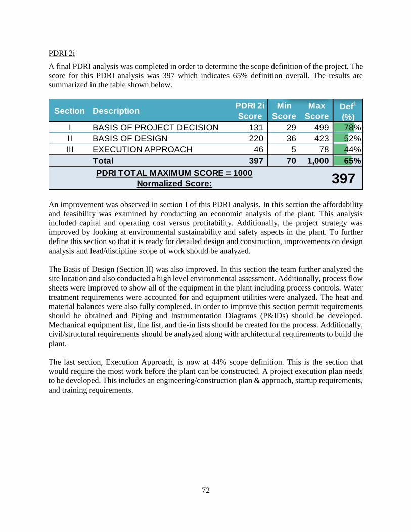
72
PDRI 2i
A final PDRI analysis was completed in order to determine the scope definition of the project. The
score for this PDRI analysis was 397 which indicates 65% definition overall. The results are
summarized in the table shown below.
An improvement was observed in section I of this PDRI analysis. In this section the affordability
and feasibility was examined by conducting an economic analysis of the plant. This analysis
included capital and operating cost versus profitability. Additionally, the project strategy was
improved by looking at environmental sustainability and safety aspects in the plant. To further
define this section so that it is ready for detailed design and construction, improvements on design
analysis and lead/discipline scope of work should be analyzed.
The Basis of Design (Section II) was also improved. In this section the team further analyzed the
site location and also conducted a high level environmental assessment. Additionally, process flow
sheets were improved to show all of the equipment in the plant including process controls. Water
treatment requirements were accounted for and equipment utilities were analyzed. The heat and
material balances were also fully completed. In order to improve this section permit requirements
should be obtained and Piping and Instrumentation Diagrams (P&IDs) should be developed.
Mechanical equipment list, line list, and tie-in lists should be created for the process. Additionally,
civil/structural requirements should be analyzed along with architectural requirements to build the
plant.
The last section, Execution Approach, is now at 44% scope definition. This is the section that
would require the most work before the plant can be constructed. A project execution plan needs
to be developed. This includes an engineering/construction plan & approach, startup requirements,
and training requirements.
Section DescriptionPDRI 2i
Score
Min
Score
Max
ScoreDef
1
(%)
I BASIS OF PROJECT DECISION 131 29 499 78%
II BASIS OF DESIGN 220 36 423 52%
III EXECUTION APPROACH 46 5 78 44%
Total 397 70 1,000 65%
PDRI TOTAL MAXIMUM SCORE = 1000
Normalized Score: 397

73
Assumptions
Methanol synthesis reaction
• Other side products such as propanol and butanol will be assumed to be negligible.
• Defined selectivity for methanol synthesis.
• High conversion of CO2 to methanol.
Catalysts used
• Catalyst life is 3 years.
Steam Reforming
• Full conversion of ethane and larger molecules.
• Same catalyst is used for water gas shift reaction.
Pre-Reformer
• Pre-reformer has 100% efficiency on decomposing heavy hydrocarbons.
• 95% conversion in the methanation reaction.
• The same catalyst is used in the Steam Reformer.
Mercury Removal Unit
• 99.9995% of Mercury removed.

74
Outstanding Issues
Utilities
• Too much water is being wasted, yields a large cost in our utilities.
• Requires a large amount of water to be used throughout the system, this yields larger
equipment than initially predicted.
• Price of methanol is low in comparison to our capital and annual cash costs. Therefore, the
plant is not profitable.
• Large reactor size also requires a large catalyst cost.
• Deionized water was included in the OBL costs, due to having an existing plant on site.
Reactor
• Maintaining heating and cooling for reactors
• Sizing of the jackets could not be completed. The necessary duties have been
factored into the project, but not the jacketing itself.
• Preforming and steam reforming reactions very endothermic. This would require
some type of outer heat source.
• Shell and tube design packed with catalyst may need to be researched.
• MeOH reactor is very exothermic. This will require a jacketing around the reactor.

75
Conclusions and Recommendations
Based on the results of the economic analysis, we decided that the plant should not be
constructed provided the given constraints. Over the operating years, the company does make a
net profit, but when scaling the value to present worth, the NPW (lifetime) is approximately
-$13 million. We have attributed the poor economic outlook of the plant to several crucial factors
pertaining to the high costs associated with: raw materials, refrigeration, waste water disposal,
and low efficiency of methanol synthesis reactor. The ATROR target is 12 percent; however, the
ATROR value for our design is significantly lower. As a result, the price of the product would
have to be elevated. Based on the economic analysis coupled with the sensitivity analyses and
the alterative processes studies, the team has decided to not build this plant.
Some recommendations for the process are:
1. Further optimize the refrigeration unit or explore replacement options as the refrigeration
unit is the main contributor to utility costs.
2. Minimize the system water flow rate while maintaining the necessary conversion. This
will reduce the waste water and thus reduce the costs associated with it.
3. Investigate different catalysts with a higher conversion and different operating conditions
for the methanol synthesis.
4. Finally, run a statistical analysis to supplement the sensitivity analyses, such as a Monte
Carlo Simulation, to determine if economic conditions will be favorable to our plant in
the future.

76
Acknowledgements
Team 15, Litlion Chemicals, would like to extend our deepest gratitude to our mentors, Mr.
Nicholas Baran and Mr. Ryan Vanston, who were always able to answer our questions and provide
technical information when needed. Their insights and experience were beyond helpful in this
project. We would also like to extend gratitude to Professor Dawn McFadden for all the technical
assistance, particularly with HYSYS. Without their hard work and dedication, this project would
not have been completed successfully.

77
Research/References
To “sweeten” sour gas (remove S impurities), it is possible to treat with amine solution in a tower.
The amine will bond with the Sulphur compounds, drawing the impurities out of the natural gas.
(Monoethanolamine (MEA), Diethanolamine (DEA), Methylenedioxyethylamphetamine
(MDEA) solutions are possible candidates) [1, 2]. Reference [11] contains HYSYS data for the
separation. Sweet gas is roughly 4 ppm H2S. Reference [12] is a report that recommends lower
amine temperatures for optimal H2S removal.
Potential rate of 42% MDEA solution for LitLion amine treatment. This number was scaled
linearly from the model given in reference [12] to achieve ~4 ppm H2S.
Research: Methods previously used
• Synthetic methanol production first began in 1923 at BASF’s
o Zinc-chromium oxide catalyst was utilized
o Operated at 25-35 MPa and 320-450°C
o Suffered from high capital and compression energy costs
• Imperial Chemical Industries (ICI) developed more active copper-zinc-alumina catalyst
o Operated at 5-10 MPa and 210-270°C
o Higher selectivity and stability
o More energy efficient and cost effective
Mercury Removal Units (MRU) [7, 8, 9]
• Can be regenerative or non-regenerative
• Non-regenerative: adsorb Hg to metal surface, frequently copper
• Good to remove Hg as quickly as possible in MRU, Hg is corrosive and will damage
process equipment
• Non-regenerative processes are simple, but have high installation costs
78
• Mercury has caused numerous aluminum exchanger failures. It amalgamates with
aluminum, resulting in a mechanical failure and gas leakage. Since the level of mercury
that can be tolerated is not established, most operators want to remove it “all.” That is,
remove it to a level where it cannot be detected with the available analytical capability.
Currently, this means reducing the mercury to less than 0.01 µg/Nm3, which
corresponds to about 1 ppt by volume.
Pre reforming [16]:
• Steam must also enter the pre-reformer to reform the hydrocarbons that are larger than
methane.
CnHm + nH2O ⟶ nCO + (n+½m) H2 (1)
CO + 3H2 ⇌ CH4 + H2O (2)
CO + H2O ⇌ CO2 + H2 (3)
References:
1. ChE 470 Course Material. Professor Dawn McFadden.
2. "Amine Treating." Newpoint Gas. n.d. Web. 14 Apr. 2017.
3. "Sour Gas Treating." Bechtel. n.d. Web. 14 Apr. 2017.
4. SYNGAS CONVERSION TO METHANOL." Liquid Fuels. National Energy Technology
Laboratory, n.d. Web. 14 Apr. 201
5. Zhang, Chundong, Ki-Won Jun, Geunjae Kwak, Yun-Jo Lee, and Hae-Gu Park. "Efficient
Utilization of Carbon Dioxide in a Gas-to-methanol Process Composed of CO2/steam-
mixed Reforming and Methanol Synthesis." Journal of CO2 Utilization16 (2016): 1-7.
Web.
6. English, A., Brown E&C, J., Rovner, J., Davies, S. and by Staff, U. 2015. Methanol. Kirk-
Othmer Encyclopedia of Chemical Technology. 1–19
7. "Hydrogen Separations in Syngas Processes." Membrane Technology and Research, Inc,
n.d. Web. 14 Apr. 2017
8. Eckersley, Neil, and Satyam Mishra. "Mercury Removal Options in Hydrocarbon
Processing Facilities." Honeywell UOP. N.p., 2012. Web. 14 Apr. 2017.
9. "UOP Mercury Removal for Natural Gas Production." Honeywell. UOP, n.d. Web. 14 Apr.
2017.
10. Markovs, John. "OPTIMIZED MERCURY REMOVAL IN GAS PLANTS." UOP
Honeywell. Honeywell, n.d. Web. 14 Apr. 2017.
11. Phillips, Steven D., and Joan K. Tarud. "Gasoline from Wood via Integrated Gasification,
Synthesis, and Methanol-to Gasoline Technologies." DEP. NREL, n.d. Web. 14 Apr. 2017.
12. Dyment, Jennifer. "Acid Gas Cleaning Using DEPG Physical Solvents: Validation with
Experimental and Plant Data." Aspentech. Aspen Technology, Inc, n.d. Web. 14 Apr. 2017
13. Satyadileep, D. "Improve Amine Unit Efficiency by Optimizing Operating
Conditions." Gas Processing. Gulf Publishing Company, n.d. Web. 14 Apr. 2017.

79
14. "PRE-REFORMING FOR HYDROGEN." Johnson Matthey Process Technologies. JM,
n.d. Web. 14 Apr. 2017
15. "Sour Gas Sweetening." PetroWiki. N.p., n.d. Web. 14 Apr. 2017
16. Cross, J. "An Introduction to Pre-reforming Catalysis." Pre-Reforming in Syngas Plants.
JM, n.d. Web. 14 Apr. 2017.

80
Appendix A
Equilibrium Data
Table 18: Equilibrium Constants for Gas Phase Reactions [1]
Equilibrium Constants (Keq) for Gas Phase Reactions
Temp.
( F ) 446 644 752 923 1139 1508 1652
CH4 Steam
Reform 1.5E-09 3.9E-06 0.0001 7.1E-03 5.5E-01 1.8E+02 1.1E+03
C2H6 Steam
Reform 2.4E-10 1E-4 2.2E-02 2.5E+01 3.3E+04 4.6E+08 1E+10
C3H8 Steam
Reform 4.7E-12 1E-4 1.1E-01 1.1E+03 1.3E+07 3.1E+12 1.7E+14
Water Shift 100 2.4E+01 1.4E+01 6.22 2.84 1 7.1E-01
NH3
Synthesis 2.5E-01 3.6E-02 1.6E-02 5.5E-03 1.8E-03 4.4E-04 2.7E-04
CH3OH
Synthesis CO 9.1E-3 1.8E-4 3.9E-05 5.2E-06 7.7E-07 7.8E-08 3.9E-08
CH3OH
Synthesis
CO2
1.4E+26 8.8E+19 2.6E+17 1.7E+14 1.5E+11 3.2E+7 2.6E+6
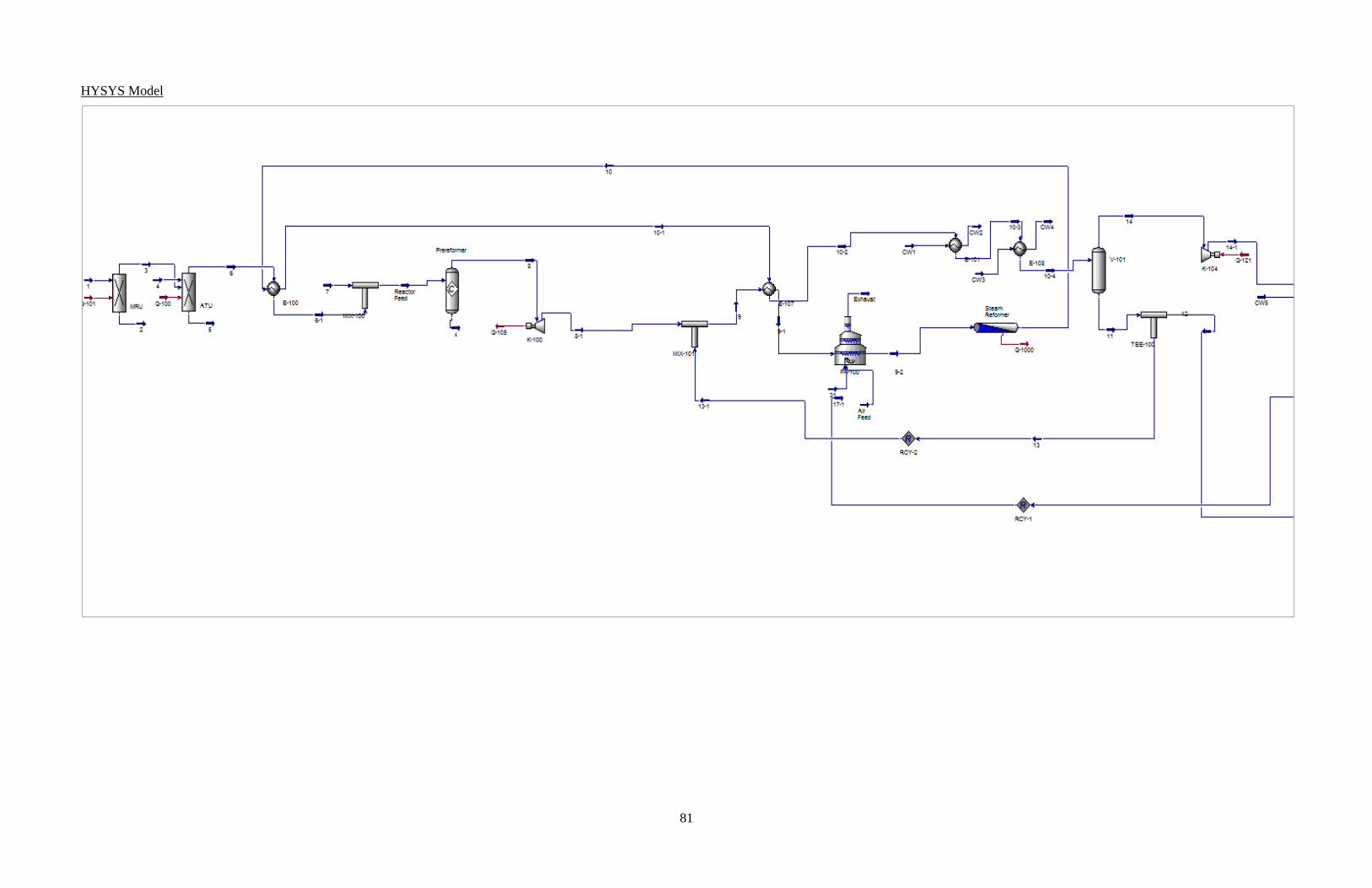
81
HYSYS Model

82
HYSYS Model Continued

83
HYSYS Model Verification
Fresh water purity 1.00 wt frac.
lbs/lbmol
Methane 16.043
Water 18.015
Methanol 32.042
Ammonia 17.031
Natural Gas Comments
Target flow 2744.00 mols/hr
NG Flow in 49289.11 lbs/hr
2744.00 mols/hr At Design Rate
Methane
Mole Fraction in NG 0.9011
Methane In 39668.22 lbs/hr
2472.62 mols/hr
Fresh Water
Fresh water purity 1.00 wt frac.
Fresh water in 150000.00 lbs/hr
Recycle to Reformer
Recycle flow 400000.00 lbs/hr
H2O in recycle 400000.00 lbs/hr
CH4 in recycle 0.00 lbs/hr
Water flow to reformer 550000.00 lbs/hr
30530.11 mols/hr
CH4 flow to reformer 39668.22 lbs/hr
2472.62 mols/hr
H2O/CH4 12.35 Outside Normal Range
Other Feeds
MDEA/H2O 124245.00 lbs/hr
lbs/hr
Steam Reformer Reactor
T at inlet (all feeds) 1100.00 F In Range of Data
T at product outlet 1100.00 F In Range of Data
Methanol Reactor
T at inlet (all feeds) 500.00 F In Range of DataT at product outlet 520.00 F In Range of Data
CH3OH feed to MeOH R 0.00 lbs/hr 99.6C2H5OH feed to MeOH R 0.00 lbs/hr 0.25HCOOCH3 feed to MeOH 0.00 lbs/hr 0.15CH3OH out of MEOH R 77237.98 lbs/hr
C2H5OH out of MEOH R 250.00 lbs/hr
HCOOCH3 out of MEOH R50.00 lbs/hr
CH3OH selectivity 0.9961 wt frac Acceptable Selectivity
C2H5OH selectivity 0.0032 wt frac Acceptable Selectivity
HCOOCH3 selectivity 0.0006 wt frac Acceptable Selectivity
Methanol
Target Product purity 0.9985 wt. frac.
Target CH4 Conversion 0.900 mol frac
Target CH3OH rate 71304.87 lbs/hr
CH3OH in product 76767.49 lbs/hr
Total product rate 76846.57 lbs/hr Meets Target
Product Purity 0.9990 Meets Spec
Waste/Other Streams
Mercury Separation 11.01 lbs/hr
H2S Separation 125653.50 lbs/hr
Recycle Purge 16122.07 lbs/hr
Waste Water 104899.20 lbs/hr
lbs/hr
lbs/hr
Overall Mass Balance 0.00% Mass Balanced
Team target
HYSYS Values - should = HYSYS
Stream Labels to change
Base Case
Natural Gas Comments Natural Gas Comments
Target flow 2469.60 mols/hr Target flow 2744.00 mols/hr
NG Flow in 44360.20 lbs/hr NG Flow in 49289.11 lbs/hr
2471.00 mols/hr At Target Rate 2744.00 mols/hr At Design Rate
Methane Methane
Mole Fraction in NG 0.9011 Mole Fraction in NG 0.9011
Methane In 35721.63 lbs/hr Methane In 39668.22 lbs/hr
2226.62 mols/hr 2472.62 mols/hr
Fresh Water Fresh Water
Fresh water purity 1.00 wt frac. Fresh water purity 1.00 wt frac.
Fresh water in 150000.00 lbs/hr Fresh water in 150000.00 lbs/hr
Recycle to Reformer Recycle to Reformer
Recycle flow 350000.00 lbs/hr Recycle flow 400000.00 lbs/hr
Fraction H2O 350000.00 lbs/hr Fraction H2O 400000.00 lbs/hr
Fraction CH4 lbs/hr Fraction CH4 lbs/hr
Water flow to reformer 500000.00 lbs/hr Water flow to reformer 550000.00 lbs/hr
27754.65 mols/hr 30530.11 mols/hr
CH4 flow to reformer 35721.63 lbs/hr CH4 flow to reformer 39668.22 lbs/hr
2226.62 mols/hr 2472.62 mols/hr
H2O/CH4 12.46 Matches Base Case H2O/CH4 12.35 Matches Base Case
Other Feeds Other Feeds
MDEA/H2O 124245.00 lbs/hr MDEA/H2O 124245.00 lbs/hr
lbs/hr lbs/hr
Steam Reformer Reactor Steam Reformer Reactor
T at inlet (all feeds) 1100.00 F Matches Base Case T at inlet (all feeds) 950.00 F In Range of Data
T at product outlet 1100.00 F T at product outlet 950.00 F In Range of Data
OK Change
Methanol Methanol
Target Product purity 0.9985 wt. frac. Target Product purity 0.9985 wt. frac.
Target CH4 Conversion 0.900 mol frac Target CH4 Conversion 0.900 mol frac
Target CH3OH rate 64210.77 lbs/hr Target CH3OH rate 71304.87 lbs/hr
CH3OH in product 69231.23 lbs/hr CH3OH in product 49387.59 lbs/hr
Total product rate 69302.32 lbs/hr Meets Target Total product rate 49433.60 lbs/hr Does not meet the production target
Product Purity 0.9990 Meets Spec Product Purity 0.9991 Meets Spec
Methanol Reactor Methanol Reactor
T at inlet (all feeds) 500.00 F Matches Base Case T at inlet (all feeds) 500.00 F Matches Base Case
T at product outlet 520.00 F T at product outlet 520.00 F
Waste/Other Streams Waste/Other Streams
Mercury Separation 11.01 lbs/hr Mercury Separation 11.01 lbs/hr
H2S Separation 125653.50 lbs/hr H2S Separation 125653.50 lbs/hr
Gas Fuel Recycle 14437.47 lbs/hr Recycle Purge 26950.25 lbs/hr
Waste Water 109341.42 lbs/hr Waste Water 121485.00 lbs/hr
lbs/hr lbs/hr
lbs/hr lbs/hr
Overall Mass Balance 0.04% Mass Balanced Overall Mass Balance 0.00% Mass Balanced
Model Verification
Change Inlet Steam Reformer Temperature >= 50FDecrease NG flow in by 10%
Model Verification

84
Natural Gas Comments Natural Gas Comments
Target flow 2744.00 mols/hr Target flow 2744.00 mols/hr
NG Flow in 49289.11 lbs/hr NG Flow in 49289.00 lbs/hr
2744.00 mols/hr At Design Rate 2744.00 mols/hr At Design Rate
Methane Methane
Mole Fraction in NG 0.9011 Mole Fraction in NG 0.9011
Methane In 39668.22 lbs/hr Methane In 39668.22 lbs/hr
2472.62 mols/hr 2472.62 mols/hr
Fresh Water Fresh Water
Fresh water purity 1.00 wt frac. Fresh water purity 1.00 wt frac.
Fresh water in 75000.00 lbs/hr Fresh water in 150000.00 lbs/hr
Recycle to Reformer Recycle to Reformer
Recycle flow 150000.00 lbs/hr Recycle flow 400000.00 lbs/hr
Fraction H2O 150000.00 lbs/hr Fraction H2O 400000.00 lbs/hr
Fraction CH4 lbs/hr Fraction CH4 lbs/hr
Water flow to reformer 225000.00 lbs/hr Water flow to reformer 550000.00 lbs/hr
12489.59 mols/hr 30530.11 mols/hr
CH4 flow to reformer 39668.22 lbs/hr CH4 flow to reformer 39668.22 lbs/hr
2472.62 mols/hr 2472.62 mols/hr
H2O/CH4 5.05 Normal Range H2O/CH4 12.35 Matches Base Case
OK Change
Other Feeds Other Feeds
MDEA/H2O 124245.00 lbs/hr MDEA/H2O 124245.00 lbs/hr
lbs/hr lbs/hr
Steam Reformer Reactor Steam Reformer Reactor
T at inlet (all feeds) 1100.00 F Matches Base Case T at inlet (all feeds) 1100.00 F Matches Base Case
T at product outlet 1100.00 F T at product outlet 1100.00 F
Methanol Methanol
Target Product purity 0.9985 wt. frac. Target Product purity 0.9985 wt. frac.
Target CH4 Conversion 0.900 mol frac Target CH4 Conversion 0.900 mol frac
Target CH3OH rate 71304.87 lbs/hr Target CH3OH rate 71304.87 lbs/hr
CH3OH in product 59695.83 lbs/hr CH3OH in product 74384.04 lbs/hr
Total product rate 59752.17 lbs/hr Does not meet the production targetTotal product rate 74471.68 lbs/hr Meets Target
Product Purity 0.9991 Meets Spec Product Purity 0.9988 Meets Spec
Methanol Reactor Methanol Reactor
T at inlet (all feeds) 500.00 F Matches Base Case T at inlet (all feeds) 435.00 F In Range of Data
T at product outlet 520.00 F T at product outlet 435.00 F In Range of Data
OK Change
Waste/Other Streams Waste/Other Streams
Mercury Separation 11.01 lbs/hr Mercury Separation 11.01 lbs/hr
H2S Separation 125653.50 lbs/hr H2S Separation 125653.50 lbs/hr
Recycle Purge 22818.73 lbs/hr Recycle Purge 19734.64 lbs/hr
Waste Water 40297.26 lbs/hr Waste Water 103664.06 lbs/hr
lbs/hr lbs/hr
lbs/hr lbs/hr
Overall Mass Balance 0.00% Mass Balanced Overall Mass Balance 0.00% Mass Balanced
Change Methanol Reactor Temperature >= 40FChange H2O/CH4 Ratio by atleast 1

85
Chemical Properties Table
Chemical Property Table Methanol Nitrogen Carbon Dioxide Methane Ethane Propane Hydrogen Iso-Butane n-Butane Iso-Pentane
Formula CH3OH N2 CO2 CH4 C2H6 C3H8 H2 iC4H10 nC4H10 iC5H12
MW 32.05 28 44.01 16.05 30.08 44.11 2.02 58.1 58.1 72.17
NBP, F 148.5 -320.4 -110.3 -258.7 -128.2 -43.6 -423.4 11 31 82
VP, mmHg 126.96 N/A 43683 N/A 28841 6397 N/A 2356 1558 N/A
Freeze, F -144 -345.8 -110.3 -305.7 -305.7 -305.7 -434.5 -255 -217 -255.6
H2O Solubility, % 1000 g/L N/A N/A N/A N/A N/A N/A Slight Slight N/A
Flammability Non-flammable Non-Flammable
UFL, % 44 N/A N/A 15 13 8.4 76 8.4 8.4 8.3
LFL, % 6 N/A N/A 5 3 1.8 4 1.6 1.6 1.4
Flash Point, F 49.5 N/A N/A -306.7 -155.2 -155.2 N/A N/A N/A -59.8
Class Flam Liquid N/A N/A Flam. Gas Flam. Gas Flam Gas Flam. Gas Flam Gas Flam Gas Flam Gas/Liq
Toxicity O2 Asphyxiation
Hazard
O2 Asphyxiation
Hazard
NIOSH REL-TWA
800 ppm
TLV-TWA, ppm 200 N/A 5000 N/A N/A N/A N/A N/A N/A 1000
TLV-C, ppm N/A N/A N/A N/A N/A N/A N/A N/A N/A N/A
OSHA PEL, ppm 200 N/A 5000 N/A N/A 1000 N/A 800 N/A N/A
IDLH, ppm N/A N/A 40000 N/A N/A 2100 N/A N/A N/A N/A
Incompatibles
Oxidizers X X X X X X X
Caustic/Acid X
Metal Chlorides X
Peroxides
Amines
Alcohols
NH3, HCN, H2S
Reactivity
Polymerization
Peroxide
Formation

86
Chemical Property Table (Continued) N-Pentane Cyclohexane Water Hydrogen Sulfide Mercury Methyl Formate Ethanol Carbon Monoxide Ammonia
Formula nC5H12 C6H12 H2O H2S Hg HCOOCH3 CH3CH2OH CO NH3
MW 72.17 84.2 18.02 34.1 200.6 60.1 46.1 28 17
NBP, F 97 177 212 -77 674 89 173 -313 -28
VP, mmHg 420 77 17.25 13376 0.0012 476 44 >26600 6460
Freeze, F -202 44 32 -122 -38 -148 -173 337 -108
H2O Solubility, % 0.04 Insoluble 100% 0.04 Insoluble 30 Miscible 2 34
Flammability
UFL, % 7.8 8 N/A 44 N/A 23 19 74 28
LFL, % 1.5 1.3 N/A 4 N/A 4.5 3.3 12.5 15
Flash Point, F -57 0 N/A N/A N/A -2 55 N/A N/A
Class Flam Gas/Liq Flam Liq N/A Flam Gas N/A Flam Liq Flam Liq Flam Gas Flam. Gas
Toxicity NIOSH REL-
TWA
100 ppm
NIOSH REL-TWA
1000 ppm
NIOSH REL-TWA
35 ppm
NIOSH REL-
TWA
25 ppm
TLV-TWA, ppm N/A N/A N/A N/A 0.00305 N/A N/A N/A N/A
TLV-C, ppm N/A N/A N/A N/A N/A N/A N/A N/A N/A
OSHA PEL, ppm 1000 300 N/A 20-50 (10 min) 0.01219 100 ppm 1000 ppm 50 ppm 50 ppm
IDLH, ppm 1500 1300 N/A 100 N/A 1200 ppm N/A
Incompatibles KOH,BrF4,Pt,Na,CH3COCl,CH3COBr BrF3,ClF3,Li Halogens
Oxidizers X X X X X X X X
Caustic/Acid X X X
Metal Chlorides X X
Peroxides
Amines X X
Alcohols
NH3, HCN, H2S X X
Reactivity
Polymerization
Peroxide Formation
Health Effects
Carcinogen

87
Component Data
TXY and XY diagrams are useful tools when separating components. The following figures are
implemented to determine how well a separation would occur. The Methanol needs to be purified
to reach the standards for sale. Also, the waste streams can be separated and possibly sold for
profit.
Figure 20:
Figure 22: XY Diagram for Methanol and Water. Figure 23: XY Diagram for Methanol and Water
Figure 21: TXY diagram for Methanol and Water. This is useful when determining the number of stages needed in a distillation
column to reach purity standards.

88
Figure 24: TXY plot for Methane and Carbon Dioxide.
Figure 25: XY Plot for Methane and Carbon Dioxide

89
Figure 5: TXY plot for Methane and Nitrogen. Figure 26:TXY plot for Methane and Nitrogen.
Figure 27: XY plot for Methane and Nitrogen.

90
Figure 28: TXY plot for Methanol and Methyl Formate.
Figure 29: XY plot for Methanol and Methyl Formate.

91
Figure 31: XY Diagram for Methanol and Ethanol
Figure 30: TXY diagram for Methanol and Ethanol. This will be useful in determining the number of stages necessary to reach
the methanol purity needed.

92
Initial BFD Created – Gate 1
1. Initial BFD design by Alexander Hatza
2. Initial BFD by Brian Klapat

93
3. Initial BFD design by Daniel Cordova
4. Initial BFD design by Sarah Ramzy

94
Code of Ethics
“LIT-Lion Chemical”
Preamble
On this, the 31st day of January, 2017, “LIT-Lion Chemical” has assembled to construct a code
ethics, detailing expectations and goals for the Ch E 470 project as well as procedures and
schedules for regular meetings. Failure to comply with these standards will result in the strict
proceedings detailed in Section III [Retribution].
Section I. Main Body
All members of “LIT-Lion Chemical” will hold paramount the integrity and dignity of both
the engineering profession and The Pennsylvania State University by:
● Providing honest and truthful work;
● Being attentive, respectful, and helpful to their mentor, Professor McFadden, and
teammates;
● Being willing to provide assistance to teammates to help further the overall progress of
the project;
● Providing the deliverables for projects within the allotted time frame;
● Completing an equal amount of work for the given assignment;
● Seeking help from other teammates when needed, but never asking for someone to
complete the work;
● Treating the project seriously and always working to their fullest potential to ensure the
completion of the project or assignment in a professional and timely manner;
Section II. Regulations
● All team members shall attend the team meetings. The team meetings are scheduled for
Tuesdays 3:00 pm to 6:00 pm. If need be, additional time blocks will be scheduled for
Wednesday evenings and/ or weekends. For these meetings, all team members must agree

95
on the time to be scheduled to ensure availability of all parties.
● If it is unavoidable for a team member to miss a meeting, that meeting will not count
towards absence. These reasons include: emergencies, religious ceremonies, exams,
injury, and illness.
● Missing a meetings for reasons such as: not setting an alarm, missing the bus, forgetting
the meeting time, etc. are not excusable and will have consequences.
● All team members must have their share of the assignment done at least one full day
before the assignment is due. This ensures assignment completion and revision by
groupmates.
● If for some reason a team member will not be able to achieve this, it is his/her
responsibility to update the team in a timely fashion.
● During meetings, all team members should be attentive. Avoid cell phone use, side
conversations, and other distractions such as social media. Team members must be
prepared for the meetings in order to avoid delays in team progress.
● Any questions, comments, or concerns should be brought up during the meeting or in
the GroupMe.
● Ideas and suggestions presented during meetings should be respected and analyzed by all
team members.
● Team members will not falsify any data or materials in pursuit of project excellence.
● All team members will strive to maintain human and environmental health in designing
the project plant.
Section III. Retribution
The following penalties shall apply to any member of “LIT-Lion Chemical” found to be in
violation of the code of ethics by his or her teammates. A two to one majority, among the peers
of the accused, must be found in group proceedings in order to determine culpability for any
individual infraction. Abstentions in voting leading to a tie vote shall acquit the defendant.
● First offense: Apologize (informal).
● Second offense: Apologize (formal, written; GroupMe is acceptable).

96
● Third and further offenses: Do the most annoying part of the next gate section.
● If the non-offending parties can unanimously agree that a particular infraction would not
be redeemed with any of the aforementioned punishments, a replacement course of action
can be chosen unanimously on a case by case basis.
Signature:
Daniel Cordova Bernal, Alexander Hatza, Brian Klapat, Sarah Ramzy

97
Appendix B
PDRI – Score Chart Summary
Note: *
Project: Senior Design Project
Type of Project: Methanol Synthesis Plant
Project Location: Enter on Cover Page
Owner/Client: Enter on Cover Page
Project No.: Gate 3
Other Control No.: Enter on Cover Page
Stage PDRI 1:
Feasibility
PDRI 2:
Concept
PDRI 2i:
Detailed
Scope
PDRI 3:
Detailed
Scope
Normalized
Score653 516 397 NA
Score 653 516 397 -
Max Score 1,000 1,000 1,000 -
Total Max Score 1,000 1,000 1,000 1,000
Typical Min * 550 450 300 150
Typical Max * 800 600 450 250
Typical range of scores are based on experience on PDRI tools since 1996.
-
100
200
300
400
500
600
700
800
900
1,000
No
rmal
ize
d S
core
Front End Planning Stage
PDRI Score Chart Summary
Normalized Score Typical Min * Typical Max *

98
PDRI 1 – Table Summary of Results
Section DescriptionPDRI 1
Score
Min
Score
Max
ScoreDef
1
(%)
I BASIS OF PROJECT DECISION 269 29 499 49%
II BASIS OF DESIGN 318 36 423 27%
III EXECUTION APPROACH 66 5 78 16%
Total 653 70 1,000 37%
Category DescriptionPDRI 1
Score
Min
Score
Max
ScoreDef
1
(%)A MANUFACTURING OBJECTIVES CRITERIA 28 3 45 40%
B BUSINESS OBJECTIVES 97 11 213 57%
C BASIC DATA RESEARCH & DEVELOPMENT 56 4 94 42%
D PROJECT SCOPE 75 11 120 41%
E VALUE ENGINEERING 13 - 27 52%
F SITE INFORMATION 78 8 104 27%
G PROCESS/MECHANICAL 135 15 196 34%
H EQUIPMENT SCOPE 18 3 33 50%
I CIVIL, STRUCTURAL, & ARCHITECTURAL 19 2 19 0%
J INFRASTRUCTURE 22 3 25 14%
K INSTRUMENT & ELECTRICAL 46 5 46 0%
L PROCUREMENT STRATEGY 15 1 16 7%
M DELIVERABLES 6 - 9 33%
N PROJECT CONTROL 10 1 17 44%
P PROJECT EXECUTION PLAN 35 3 36 3%
Total 653 70 1,000 37%
Top 10
ElementsDescription
PDRI 1
Score
Min
Score
Max
ScoreDef
1
(%)B.1 Products 22 1 56 62%
B.5 Capacities 21 2 55 64%
C.1 Technology 39 2 54 29%
C.2 Processes 17 2 40 61%
G.1 Process Flow Sheets 8 2 36 82%
F.1 Site Location 18 2 32 47%
G.3 Piping and Instrumentation Diagrams (P&IDs) 31 2 31 0%
D.3 Site Characteristics Available vs. Required 22 2 29 26%
B.2 Market Strategy 16 2 26 42%
D.1 Project Objectives Statement 14 2 25 48%
Total 208 19 384 48%
Notes:
1 - Definition percentage indicates the level of completeness of specific Section, Category and Element.
653 PDRI TOTAL MAXIMUM SCORE = 1000
Normalized Score:
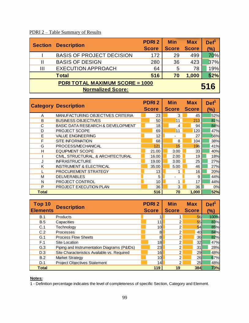
99
PDRI 2 – Table Summary of Results
Section DescriptionPDRI 2
Score
Min
Score
Max
ScoreDef
1
(%)
I BASIS OF PROJECT DECISION 172 29 499 70%
II BASIS OF DESIGN 280 36 423 37%
III EXECUTION APPROACH 64 5 78 19%
Total 516 70 1,000 52%
Category DescriptionPDRI 2
Score
Min
Score
Max
ScoreDef
1
(%)A MANUFACTURING OBJECTIVES CRITERIA 23 3 45 52%
B BUSINESS OBJECTIVES 50 11 213 81%
C BASIC DATA RESEARCH & DEVELOPMENT 18 4 94 84%
D PROJECT SCOPE 69 11 120 47%
E VALUE ENGINEERING 12 - 27 56%
F SITE INFORMATION 68 8 104 38%
G PROCESS/MECHANICAL 121 15 196 41%
H EQUIPMENT SCOPE 21.00 3.00 33 40%
I CIVIL, STRUCTURAL, & ARCHITECTURAL 16.00 2.00 19 18%
J INFRASTRUCTURE 19.00 3.00 25 27%
K INSTRUMENT & ELECTRICAL 35.00 5.00 46 27%
L PROCUREMENT STRATEGY 13 1 16 20%
M DELIVERABLES 5 - 9 44%
N PROJECT CONTROL 10 1 17 44%
P PROJECT EXECUTION PLAN 36 3 36 0%
Total 516 70 1,000 52%
Top 10
ElementsDescription
PDRI 2
Score
Min
Score
Max
ScoreDef
1
(%)B.1 Products 1 1 56 100%
B.5 Capacities 11 2 55 83%
C.1 Technology 10 2 54 85%
C.2 Processes 8 2 40 84%
G.1 Process Flow Sheets 8 2 36 82%
F.1 Site Location 18 2 32 47%
G.3 Piping and Instrumentation Diagrams (P&IDs) 23 2 31 28%
D.3 Site Characteristics Available vs. Required 16 2 29 48%
B.2 Market Strategy 10 2 26 67%
D.1 Project Objectives Statement 14 2 25 48%
Total 119 19 384 73%
Notes:
1 - Definition percentage indicates the level of completeness of specific Section, Category and Element.
PDRI TOTAL MAXIMUM SCORE = 1000
Normalized Score: 516

100
PDRI 2i – Table Summary of Results
Section DescriptionPDRI 2i
Score
Min
Score
Max
ScoreDef
1
(%)
I BASIS OF PROJECT DECISION 131 29 499 78%
II BASIS OF DESIGN 220 36 423 52%
III EXECUTION APPROACH 46 5 78 44%
Total 397 70 1,000 65%
Category DescriptionPDRI 2i
Score
Min
Score
Max
ScoreDef
1
(%)A MANUFACTURING OBJECTIVES CRITERIA 12 3 45 79%
B BUSINESS OBJECTIVES 36 11 213 88%
C BASIC DATA RESEARCH & DEVELOPMENT 18 4 94 84%
D PROJECT SCOPE 54 11 120 61%
E VALUE ENGINEERING 11 - 27 59%
F SITE INFORMATION 46 8 104 60%
G PROCESS/MECHANICAL 98 15 196 54%
H EQUIPMENT SCOPE 21 3 33 40%
I CIVIL, STRUCTURAL, & ARCHITECTURAL 13 2 19 35%
J INFRASTRUCTURE 14 3 25 50%
K INSTRUMENT & ELECTRICAL 28 5 46 44%
L PROCUREMENT STRATEGY 10 1 16 40%
M DELIVERABLES 2 - 9 78%
N PROJECT CONTROL 11 1 17 38%
P PROJECT EXECUTION PLAN 23 3 36 39%
Total 397 70 1,000 65%
Top 10
ElementsDescription
PDRI 2i
Score
Min
Score
Max
ScoreDef
1
(%)B.1 Products 1 1 56 100%
B.5 Capacities 11 2 55 83%
C.1 Technology 10 2 54 85%
C.2 Processes 8 2 40 84%
G.1 Process Flow Sheets 8 2 36 82%
F.1 Site Location 10 2 32 73%
G.3 Piping and Instrumentation Diagrams (P&IDs) 23 2 31 28%
D.3 Site Characteristics Available vs. Required 16 2 29 48%
B.2 Market Strategy 5 2 26 88%
D.1 Project Objectives Statement 8 2 25 74%
Total 100 19 384 78%
Notes:
1 - Definition percentage indicates the level of completeness of specific Section, Category and Element.
PDRI TOTAL MAXIMUM SCORE = 1000
Normalized Score: 397
2i Summary Definition
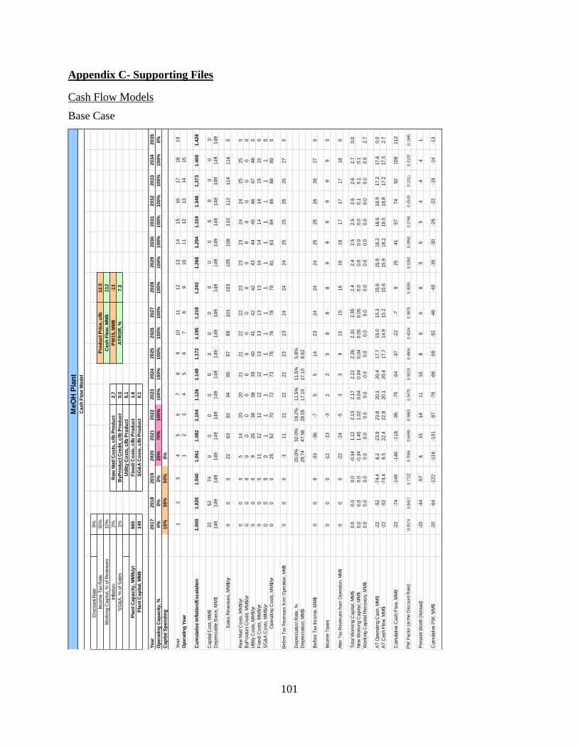
101
Appendix C- Supporting Files
Cash Flow Models
Base Case
MeO
H P
lan
tC
as
h F
low
Mo
de
l
Dis
co
unt R
ate
9%
Inco
me
Ta
x R
ate
35
%P
rod
uc
t P
ric
e, c
/lb
12
.5
Wo
rkin
g C
ap
ita
l, %
of R
eve
nue
s1
0%
Ca
sh
Flo
w, M
M$
11
2
Infla
tio
n2
%R
aw
Ma
tl C
os
ts, c
/lb
Pro
du
ct
2.7
PW
15
, M
M$
-13
SG
&A
, %
of S
ale
s1
%B
yP
rod
uc
t C
red
it, c
/lb
Pro
du
ct
0.0
AT
RO
R, %
7.3
Uti
lity
Co
sts
, c
/lb
Pro
du
ct
5.1
Pla
nt
Ca
pa
cit
y, M
Mlb
/yr
66
5F
ixe
d/ C
os
ts, c
/lb
Pro
du
ct
1.6
Pla
nt
Ca
pit
al, M
M$
14
9S
G&
A C
os
ts, c
/lb
Pro
du
ct
0.1
Ye
ar
20
17
20
18
20
19
20
20
20
21
20
22
20
23
20
24
20
25
20
26
20
27
20
28
20
29
20
30
20
31
20
32
20
33
20
34
20
35
Op
era
tin
g C
ap
ac
ity
, %
0%
0%
0%
25
%7
0%
10
0%
10
0%
10
0%
10
0%
10
0%
10
0%
10
0%
10
0%
10
0%
10
0%
10
0%
10
0%
10
0%
0%
Ca
pit
al S
pe
nd
ing
15
%3
5%
50
%0
%
Ye
ar
12
34
56
78
91
01
11
21
31
41
51
61
71
81
9
Op
era
tin
g Y
ea
r1
23
45
67
89
10
11
12
13
14
15
Cu
mu
lati
ve
In
fla
tio
n/E
sc
ala
tio
n1
.00
01
.02
01
.04
01
.06
11
.08
21
.10
41
.12
61
.14
91
.17
21
.19
51
.21
91
.24
31
.26
81
.29
41
.31
91
.34
61
.37
31
.40
01
.42
8
Ca
pita
l Co
st, M
M$
22
52
74
00
00
00
00
00
00
00
00
De
pre
cia
ble
Ba
sis
, M
M$
14
91
49
14
91
49
14
91
49
14
91
49
14
91
49
14
91
49
14
91
49
14
91
49
14
91
49
14
9
Sa
les R
eve
nue
s, M
M$
/yr
00
02
26
39
29
49
59
79
91
01
10
31
05
10
81
10
11
21
14
11
60
Ra
w M
atl
Co
sts
, M
M$
/yr
00
05
14
20
20
21
21
22
22
23
23
23
24
24
25
25
0
ByP
rod
uct C
red
it, M
M$
/yr
00
00
00
00
00
00
00
00
00
0
Utilit
y C
osts
, M
M$
/yr
00
09
26
38
38
39
40
41
42
42
43
44
45
46
47
48
0
Fix
ed
/ C
osts
, M
M$
/yr
00
01
11
21
21
21
21
31
31
31
31
41
41
41
41
51
50
SG
&A
Co
sts
, M
M$
/yr
00
00
11
11
11
11
11
11
11
0
Op
era
ting
Co
sts
, M
M$
/yr
00
02
55
27
07
27
37
57
67
87
98
18
38
48
68
88
90
Befo
re T
ax
Reve
nues fro
m O
pera
tion, M
M$
00
0-3
11
21
22
22
23
23
24
24
24
25
25
26
26
27
0
De
pre
cia
tio
n R
ate
, %
20
.0%
32
.0%
19
.2%
11
.5%
11
.5%
5.8
%
De
pre
cia
tio
n, M
M$
29
.74
47
.58
28
.55
17
.10
17
.10
8.6
2
Be
fore
Ta
x In
co
me
, M
M$
00
0-3
3-3
6-7
55
14
23
24
24
24
25
25
26
26
27
0
Inco
me
Ta
xes
00
0-1
2-1
3-3
22
58
88
99
99
99
0
After
Tax
Reve
nues fro
m O
pera
tion, M
M$
00
0-2
2-2
4-5
33
91
51
51
61
61
61
71
71
71
80
To
tal W
ork
ing
Ca
pita
l, M
M$
0.0
0.0
0.0
-0.3
41
.12
2.1
32
.17
2.2
22
.26
2.3
12
.35
2.4
2.4
2.5
2.5
2.6
2.6
2.7
0.0
Ne
w W
ork
ing
Ca
pita
l, M
M$
0.0
0.0
0.0
-0.3
41
.45
1.0
20
.04
0.0
40
.04
0.0
50
.05
0.0
0.0
0.0
0.0
0.1
0.1
0.1
Wo
rkin
g C
ap
ita
l Re
co
very
, M
M$
0.0
0.0
0.0
0.0
0.0
0.0
0.0
0.0
0.0
0.0
0.0
0.0
0.0
0.0
0.0
0.0
0.0
0.0
2.7
AT
Op
era
ting
Ca
sh, M
M$
-22
-52
-74
.48
.22
3.9
23
.82
0.1
20
.41
7.7
15
.01
5.3
15
.61
5.9
16
.21
6.6
16
.91
7.2
17
.60
.0
AT
Ca
sh F
low
, M
M$
-22
-52
-74
.48
.52
2.4
22
.82
0.1
20
.41
7.7
14
.91
5.2
15
.61
5.9
16
.21
6.5
16
.81
7.2
17
.52
.7
Cum
ula
tive
Ca
sh F
low
, M
M$
-22
-74
-14
9-1
40
-11
8-9
5-7
5-5
4-3
7-2
2-7
92
54
15
77
49
21
09
11
2
PW
Facto
r (a
t th
e D
iscount R
ate
)0.9
174
0.8
417
0.7
722
0.7
084
0.6
499
0.5
963
0.5
470
0.5
019
0.4
604
0.4
224
0.3
875
0.3
555
0.3
262
0.2
992
0.2
745
0.2
519
0.2
311
0.2
120
0.1
945
Pre
se
nt W
ort
h (
Annua
l)-2
0-4
4-5
76
15
14
11
10
86
66
55
54
44
1
Cum
ula
tive
PW
, M
M$
-20
-64
-12
2-1
16
-10
1-8
7-7
6-6
6-5
8-5
2-4
6-4
0-3
5-3
0-2
6-2
2-1
8-1
4-1
3

102
Sensitivity Analysis 1: Raw Material Cost = 3.5 c/lb product
MeO
H P
lan
tC
as
h F
low
Mo
de
l
Dis
co
unt R
ate
9%
Inco
me
Ta
x R
ate
35
%P
rod
uc
t P
ric
e, c
/lb
12
.5
Wo
rkin
g C
ap
ita
l, %
of R
eve
nue
s1
0%
Ca
sh
Flo
w, M
M$
54
Infla
tio
n2
%R
aw
Ma
tl C
os
ts, c
/lb
Pro
du
ct
3.5
PW
15
, M
M$
-35
SG
&A
, %
of S
ale
s1
%B
yP
rod
uc
t C
red
it, c
/lb
Pro
du
ct
0.0
AT
RO
R, %
4.0
Uti
lity
Co
sts
, c
/lb
Pro
du
ct
5.1
Pla
nt
Ca
pa
cit
y, M
Mlb
/yr
66
5F
ixe
d/ C
os
ts, c
/lb
Pro
du
ct
1.6
Pla
nt
Ca
pit
al, M
M$
14
9S
G&
A C
os
ts, c
/lb
Pro
du
ct
0.1
Ye
ar
20
17
20
18
20
19
20
20
20
21
20
22
20
23
20
24
20
25
20
26
20
27
20
28
20
29
20
30
20
31
20
32
20
33
20
34
20
35
Op
era
tin
g C
ap
ac
ity
, %
0%
0%
0%
25
%7
0%
10
0%
10
0%
10
0%
10
0%
10
0%
10
0%
10
0%
10
0%
10
0%
10
0%
10
0%
10
0%
10
0%
0%
Ca
pit
al S
pe
nd
ing
15
%3
5%
50
%0
%
Ye
ar
12
34
56
78
91
01
11
21
31
41
51
61
71
81
9
Op
era
tin
g Y
ea
r1
23
45
67
89
10
11
12
13
14
15
Cu
mu
lati
ve
In
fla
tio
n/E
sc
ala
tio
n1
.00
01
.02
01
.04
01
.06
11
.08
21
.10
41
.12
61
.14
91
.17
21
.19
51
.21
91
.24
31
.26
81
.29
41
.31
91
.34
61
.37
31
.40
01
.42
8
Ca
pita
l Co
st, M
M$
22
52
74
00
00
00
00
00
00
00
00
De
pre
cia
ble
Ba
sis
, M
M$
14
91
49
14
91
49
14
91
49
14
91
49
14
91
49
14
91
49
14
91
49
14
91
49
14
91
49
14
9
Sa
les R
eve
nue
s, M
M$
/yr
00
02
26
39
29
49
59
79
91
01
10
31
05
10
81
10
11
21
14
11
60
Ra
w M
atl
Co
sts
, M
M$
/yr
00
06
18
26
26
27
27
28
28
29
30
30
31
31
32
33
0
ByP
rod
uct C
red
it, M
M$
/yr
00
00
00
00
00
00
00
00
00
0
Utilit
y C
osts
, M
M$
/yr
00
09
26
38
38
39
40
41
42
42
43
44
45
46
47
48
0
Fix
ed
/ C
osts
, M
M$
/yr
00
01
11
21
21
21
21
31
31
31
31
41
41
41
41
51
50
SG
&A
Co
sts
, M
M$
/yr
00
00
11
11
11
11
11
11
11
0
Op
era
ting
Co
sts
, M
M$
/yr
00
02
75
67
67
87
98
18
28
48
68
78
99
19
39
59
70
Befo
re T
ax
Reve
nues fro
m O
pera
tion, M
M$
00
0-5
71
61
61
61
71
71
71
81
81
81
91
91
92
00
De
pre
cia
tio
n R
ate
, %
20
.0%
32
.0%
19
.2%
11
.5%
11
.5%
5.8
%
De
pre
cia
tio
n, M
M$
29
.74
47
.58
28
.55
17
.10
17
.10
8.6
2
Be
fore
Ta
x In
co
me
, M
M$
00
0-3
4-4
0-1
3-1
-18
17
17
18
18
18
19
19
19
20
0
Inco
me
Ta
xes
00
0-1
2-1
4-5
00
36
66
66
77
77
0
After
Tax
Reve
nues fro
m O
pera
tion, M
M$
00
0-2
2-2
6-8
-1-1
51
11
11
11
21
21
21
21
31
30
To
tal W
ork
ing
Ca
pita
l, M
M$
0.0
0.0
0.0
-0.4
70
.73
1.5
61
.60
1.6
31
.66
1.6
91
.73
1.8
1.8
1.8
1.9
1.9
1.9
2.0
0.0
Ne
w W
ork
ing
Ca
pita
l, M
M$
0.0
0.0
0.0
-0.4
71
.20
0.8
40
.03
0.0
30
.03
0.0
30
.03
0.0
0.0
0.0
0.0
0.0
0.0
0.0
Wo
rkin
g C
ap
ita
l Re
co
very
, M
M$
0.0
0.0
0.0
0.0
0.0
0.0
0.0
0.0
0.0
0.0
0.0
0.0
0.0
0.0
0.0
0.0
0.0
0.0
2.0
AT
Op
era
ting
Ca
sh, M
M$
-22
-52
-74
.47
.32
1.4
20
.21
6.4
16
.61
3.8
11
.01
1.2
11
.51
1.7
11
.91
2.2
12
.41
2.6
12
.90
.0
AT
Ca
sh F
low
, M
M$
-22
-52
-74
.47
.82
0.2
19
.31
6.3
16
.51
3.8
11
.01
1.2
11
.41
1.6
11
.91
2.1
12
.41
2.6
12
.92
.0
Cum
ula
tive
Ca
sh F
low
, M
M$
-22
-74
-14
9-1
41
-12
1-1
01
-85
-69
-55
-44
-33
-21
-10
21
42
73
95
25
4
PW
Facto
r (a
t th
e D
iscount R
ate
)0.9
174
0.8
417
0.7
722
0.7
084
0.6
499
0.5
963
0.5
470
0.5
019
0.4
604
0.4
224
0.3
875
0.3
555
0.3
262
0.2
992
0.2
745
0.2
519
0.2
311
0.2
120
0.1
945
Pre
se
nt W
ort
h (
Annua
l)-2
0-4
4-5
76
13
12
98
65
44
44
33
33
0
Cum
ula
tive
PW
, M
M$
-20
-64
-12
2-1
16
-10
3-9
2-8
3-7
4-6
8-6
3-5
9-5
5-5
1-4
8-4
4-4
1-3
8-3
5-3
5

103
Sensitivity Analysis 2: Product Price = 11.5 c/lb product
MeO
H P
lan
tC
as
h F
low
Mo
de
l
Dis
co
unt R
ate
9%
Inco
me
Ta
x R
ate
35
%P
rod
uc
t P
ric
e, c
/lb
11
.5
Wo
rkin
g C
ap
ita
l, %
of R
eve
nue
s1
0%
Ca
sh
Flo
w, M
M$
38
Infla
tio
n2
%R
aw
Ma
tl C
os
ts, c
/lb
Pro
du
ct
2.7
PW
15
, M
M$
-41
SG
&A
, %
of S
ale
s1
%B
yP
rod
uc
t C
red
it, c
/lb
Pro
du
ct
0.0
AT
RO
R, %
2.9
Uti
lity
Co
sts
, c
/lb
Pro
du
ct
5.1
Pla
nt
Ca
pa
cit
y, M
Mlb
/yr
66
5F
ixe
d/ C
os
ts, c
/lb
Pro
du
ct
1.6
Pla
nt
Ca
pit
al, M
M$
14
9S
G&
A C
os
ts, c
/lb
Pro
du
ct
0.1
Ye
ar
20
17
20
18
20
19
20
20
20
21
20
22
20
23
20
24
20
25
20
26
20
27
20
28
20
29
20
30
20
31
20
32
20
33
20
34
20
35
Op
era
tin
g C
ap
ac
ity
, %
0%
0%
0%
25
%7
0%
10
0%
10
0%
10
0%
10
0%
10
0%
10
0%
10
0%
10
0%
10
0%
10
0%
10
0%
10
0%
10
0%
0%
Ca
pit
al S
pe
nd
ing
15
%3
5%
50
%0
%
Ye
ar
12
34
56
78
91
01
11
21
31
41
51
61
71
81
9
Op
era
tin
g Y
ea
r1
23
45
67
89
10
11
12
13
14
15
Cu
mu
lati
ve
In
fla
tio
n/E
sc
ala
tio
n1
.00
01
.02
01
.04
01
.06
11
.08
21
.10
41
.12
61
.14
91
.17
21
.19
51
.21
91
.24
31
.26
81
.29
41
.31
91
.34
61
.37
31
.40
01
.42
8
Ca
pita
l Co
st, M
M$
22
52
74
00
00
00
00
00
00
00
00
De
pre
cia
ble
Ba
sis
, M
M$
14
91
49
14
91
49
14
91
49
14
91
49
14
91
49
14
91
49
14
91
49
14
91
49
14
91
49
14
9
Sa
les R
eve
nue
s, M
M$
/yr
00
02
05
88
48
68
89
09
19
39
59
79
91
01
10
31
05
10
70
Ra
w M
atl
Co
sts
, M
M$
/yr
00
05
14
20
20
21
21
22
22
23
23
23
24
24
25
25
0
ByP
rod
uct C
red
it, M
M$
/yr
00
00
00
00
00
00
00
00
00
0
Utilit
y C
osts
, M
M$
/yr
00
09
26
38
38
39
40
41
42
42
43
44
45
46
47
48
0
Fix
ed
/ C
osts
, M
M$
/yr
00
01
11
21
21
21
21
31
31
31
31
41
41
41
41
51
50
SG
&A
Co
sts
, M
M$
/yr
00
00
11
11
11
11
11
11
11
0
Op
era
ting
Co
sts
, M
M$
/yr
00
02
55
27
07
27
37
57
67
87
98
18
28
48
68
88
90
Befo
re T
ax
Reve
nues fro
m O
pera
tion, M
M$
00
0-5
61
41
41
51
51
51
61
61
61
61
71
71
71
80
De
pre
cia
tio
n R
ate
, %
20
.0%
32
.0%
19
.2%
11
.5%
11
.5%
5.8
%
De
pre
cia
tio
n, M
M$
29
.74
47
.58
28
.55
17
.10
17
.10
8.6
2
Be
fore
Ta
x In
co
me
, M
M$
00
0-3
5-4
1-1
5-3
-26
15
16
16
16
16
17
17
17
18
0
Inco
me
Ta
xes
00
0-1
2-1
4-5
-1-1
25
56
66
66
66
0
After
Tax
Reve
nues fro
m O
pera
tion, M
M$
00
0-2
3-2
7-9
-2-2
41
01
01
01
01
11
11
11
11
20
To
tal W
ork
ing
Ca
pita
l, M
M$
0.0
0.0
0.0
-0.5
10
.62
1.4
01
.43
1.4
61
.49
1.5
21
.55
1.6
1.6
1.6
1.7
1.7
1.7
1.8
0.0
Ne
w W
ork
ing
Ca
pita
l, M
M$
0.0
0.0
0.0
-0.5
11
.13
0.7
90
.03
0.0
30
.03
0.0
30
.03
0.0
0.0
0.0
0.0
0.0
0.0
0.0
Wo
rkin
g C
ap
ita
l Re
co
very
, M
M$
0.0
0.0
0.0
0.0
0.0
0.0
0.0
0.0
0.0
0.0
0.0
0.0
0.0
0.0
0.0
0.0
0.0
0.0
1.8
AT
Op
era
ting
Ca
sh, M
M$
-22
-52
-74
.47
.12
0.7
19
.11
5.3
15
.51
2.7
9.9
10
.11
0.3
10
.51
0.7
10
.91
1.1
11
.31
1.6
0.0
AT
Ca
sh F
low
, M
M$
-22
-52
-74
.47
.61
9.5
18
.31
5.3
15
.51
2.7
9.8
10
.01
0.2
10
.51
0.7
10
.91
1.1
11
.31
1.5
1.8
Cum
ula
tive
Ca
sh F
low
, M
M$
-22
-74
-14
9-1
41
-12
2-1
03
-88
-73
-60
-50
-40
-30
-19
-92
13
25
36
38
PW
Facto
r (a
t th
e D
iscount R
ate
)0.9
174
0.8
417
0.7
722
0.7
084
0.6
499
0.5
963
0.5
470
0.5
019
0.4
604
0.4
224
0.3
875
0.3
555
0.3
262
0.2
992
0.2
745
0.2
519
0.2
311
0.2
120
0.1
945
Pre
se
nt W
ort
h (
Annua
l)-2
0-4
4-5
75
13
11
88
64
44
33
33
32
0
Cum
ula
tive
PW
, M
M$
-20
-64
-12
2-1
16
-10
4-9
3-8
4-7
7-7
1-6
7-6
3-5
9-5
6-5
2-4
9-4
7-4
4-4
2-4
1

104
Sensitivity Analysis 3: Utility Cost = 6 c/lb product
MeO
H P
lan
tC
as
h F
low
Mo
de
l
Dis
co
unt R
ate
9%
Inco
me
Ta
x R
ate
35
%P
rod
uc
t P
ric
e, c
/lb
12
.5
Wo
rkin
g C
ap
ita
l, %
of R
eve
nue
s1
0%
Ca
sh
Flo
w, M
M$
47
Infla
tio
n2
%R
aw
Ma
tl C
os
ts, c
/lb
Pro
du
ct
2.7
PW
15
, M
M$
-38
SG
&A
, %
of S
ale
s1
%B
yP
rod
uc
t C
red
it, c
/lb
Pro
du
ct
0.0
AT
RO
R, %
3.5
Uti
lity
Co
sts
, c
/lb
Pro
du
ct
6.0
Pla
nt
Ca
pa
cit
y, M
Mlb
/yr
66
5F
ixe
d/ C
os
ts, c
/lb
Pro
du
ct
1.6
Pla
nt
Ca
pit
al, M
M$
14
9S
G&
A C
os
ts, c
/lb
Pro
du
ct
0.1
Ye
ar
20
17
20
18
20
19
20
20
20
21
20
22
20
23
20
24
20
25
20
26
20
27
20
28
20
29
20
30
20
31
20
32
20
33
20
34
20
35
Op
era
tin
g C
ap
ac
ity
, %
0%
0%
0%
25
%7
0%
10
0%
10
0%
10
0%
10
0%
10
0%
10
0%
10
0%
10
0%
10
0%
10
0%
10
0%
10
0%
10
0%
0%
Ca
pit
al S
pe
nd
ing
15
%3
5%
50
%0
%
Ye
ar
12
34
56
78
91
01
11
21
31
41
51
61
71
81
9
Op
era
tin
g Y
ea
r1
23
45
67
89
10
11
12
13
14
15
Cu
mu
lati
ve
In
fla
tio
n/E
sc
ala
tio
n1
.00
01
.02
01
.04
01
.06
11
.08
21
.10
41
.12
61
.14
91
.17
21
.19
51
.21
91
.24
31
.26
81
.29
41
.31
91
.34
61
.37
31
.40
01
.42
8
Ca
pita
l Co
st, M
M$
22
52
74
00
00
00
00
00
00
00
00
De
pre
cia
ble
Ba
sis
, M
M$
14
91
49
14
91
49
14
91
49
14
91
49
14
91
49
14
91
49
14
91
49
14
91
49
14
91
49
14
9
Sa
les R
eve
nue
s, M
M$
/yr
00
02
26
39
29
49
59
79
91
01
10
31
05
10
81
10
11
21
14
11
60
Ra
w M
atl
Co
sts
, M
M$
/yr
00
05
14
20
20
21
21
22
22
23
23
23
24
24
25
25
0
ByP
rod
uct C
red
it, M
M$
/yr
00
00
00
00
00
00
00
00
00
0
Utilit
y C
osts
, M
M$
/yr
00
01
13
04
44
54
64
74
84
95
05
15
25
35
45
55
60
Fix
ed
/ C
osts
, M
M$
/yr
00
01
11
21
21
21
21
31
31
31
31
41
41
41
41
51
50
SG
&A
Co
sts
, M
M$
/yr
00
00
11
11
11
11
11
11
11
0
Op
era
ting
Co
sts
, M
M$
/yr
00
02
75
67
77
88
08
28
38
58
68
89
09
29
49
69
70
Befo
re T
ax
Reve
nues fro
m O
pera
tion, M
M$
00
0-5
71
51
51
61
61
61
71
71
71
81
81
81
91
90
De
pre
cia
tio
n R
ate
, %
20
.0%
32
.0%
19
.2%
11
.5%
11
.5%
5.8
%
De
pre
cia
tio
n, M
M$
29
.74
47
.58
28
.55
17
.10
17
.10
8.6
2
Be
fore
Ta
x In
co
me
, M
M$
00
0-3
5-4
1-1
4-2
-27
16
17
17
17
18
18
18
19
19
0
Inco
me
Ta
xes
00
0-1
2-1
4-5
-1-1
36
66
66
66
77
0
After
Tax
Reve
nues fro
m O
pera
tion, M
M$
00
0-2
3-2
7-9
-1-1
51
11
11
11
11
11
21
21
21
20
To
tal W
ork
ing
Ca
pita
l, M
M$
0.0
0.0
0.0
-0.4
90
.68
1.5
01
.53
1.5
61
.59
1.6
21
.65
1.7
1.7
1.8
1.8
1.8
1.9
1.9
0.0
Ne
w W
ork
ing
Ca
pita
l, M
M$
0.0
0.0
0.0
-0.4
91
.17
0.8
20
.03
0.0
30
.03
0.0
30
.03
0.0
0.0
0.0
0.0
0.0
0.0
0.0
Wo
rkin
g C
ap
ita
l Re
co
very
, M
M$
0.0
0.0
0.0
0.0
0.0
0.0
0.0
0.0
0.0
0.0
0.0
0.0
0.0
0.0
0.0
0.0
0.0
0.0
1.9
AT
Op
era
ting
Ca
sh, M
M$
-22
-52
-74
.47
.22
1.1
19
.71
5.9
16
.11
3.3
10
.51
0.7
11
.01
1.2
11
.41
1.6
11
.91
2.1
12
.30
.0
AT
Ca
sh F
low
, M
M$
-22
-52
-74
.47
.71
9.9
18
.91
5.9
16
.11
3.3
10
.51
0.7
10
.91
1.1
11
.41
1.6
11
.81
2.1
12
.31
.9
Cum
ula
tive
Ca
sh F
low
, M
M$
-22
-74
-14
9-1
41
-12
1-1
02
-86
-70
-57
-46
-36
-25
-14
-29
21
33
45
47
PW
Facto
r (a
t th
e D
iscount R
ate
)0.9
174
0.8
417
0.7
722
0.7
084
0.6
499
0.5
963
0.5
470
0.5
019
0.4
604
0.4
224
0.3
875
0.3
555
0.3
262
0.2
992
0.2
745
0.2
519
0.2
311
0.2
120
0.1
945
Pre
se
nt W
ort
h (
Annua
l)-2
0-4
4-5
75
13
11
98
64
44
43
33
33
0
Cum
ula
tive
PW
, M
M$
-20
-64
-12
2-1
16
-10
3-9
2-8
3-7
5-6
9-6
5-6
1-5
7-5
3-5
0-4
6-4
3-4
1-3
8-3
8

105
Sensitivity Analysis 4: Construction delayed to 4 years
MeO
H P
lan
tC
as
h F
low
Mo
de
l
Dis
co
unt R
ate
9%
Inco
me
Ta
x R
ate
35
%P
rod
uc
t P
ric
e, c
/lb
12
.5
Wo
rkin
g C
ap
ita
l, %
of R
eve
nue
s1
0%
Ca
sh
Flo
w, M
M$
91
Infla
tio
n2
%R
aw
Ma
tl C
os
ts, c
/lb
Pro
du
ct
2.7
PW
15
, M
M$
-21
SG
&A
, %
of S
ale
s1
%B
yP
rod
uc
t C
red
it, c
/lb
Pro
du
ct
0.0
AT
RO
R, %
6.1
Uti
lity
Co
sts
, c
/lb
Pro
du
ct
5.1
Pla
nt
Ca
pa
cit
y, M
Mlb
/yr
66
5F
ixe
d/ C
os
ts, c
/lb
Pro
du
ct
1.6
Pla
nt
Ca
pit
al, M
M$
14
9S
G&
A C
os
ts, c
/lb
Pro
du
ct
0.1
Ye
ar
20
17
20
18
20
19
20
20
20
21
20
22
20
23
20
24
20
25
20
26
20
27
20
28
20
29
20
30
20
31
20
32
20
33
20
34
20
35
Op
era
tin
g C
ap
ac
ity
, %
0%
0%
0%
0%
25
%7
0%
10
0%
10
0%
10
0%
10
0%
10
0%
10
0%
10
0%
10
0%
10
0%
10
0%
10
0%
10
0%
0%
Ca
pit
al S
pe
nd
ing
15
%1
5%
25
%4
5%
Ye
ar
12
34
56
78
91
01
11
21
31
41
51
61
71
81
9
Op
era
tin
g Y
ea
r1
23
45
67
89
10
11
12
13
14
15
Cu
mu
lati
ve
In
fla
tio
n/E
sc
ala
tio
n1
.00
01
.02
01
.04
01
.06
11
.08
21
.10
41
.12
61
.14
91
.17
21
.19
51
.21
91
.24
31
.26
81
.29
41
.31
91
.34
61
.37
31
.40
01
.42
8
Ca
pita
l Co
st, M
M$
22
22
37
67
00
00
00
00
00
00
00
0
De
pre
cia
ble
Ba
sis
, M
M$
14
91
49
14
91
49
14
91
49
14
91
49
14
91
49
14
91
49
14
91
49
14
91
49
14
91
49
14
9
Sa
les R
eve
nue
s, M
M$
/yr
00
00
22
64
94
95
97
99
10
11
03
10
51
08
11
01
12
11
41
16
0
Ra
w M
atl
Co
sts
, M
M$
/yr
00
00
51
42
02
12
12
22
22
32
32
32
42
42
52
50
ByP
rod
uct C
red
it, M
M$
/yr
00
00
00
00
00
00
00
00
00
0
Utilit
y C
osts
, M
M$
/yr
00
00
92
63
83
94
04
14
24
24
34
44
54
64
74
80
Fix
ed
/ C
osts
, M
M$
/yr
00
01
11
21
21
21
21
31
31
31
31
41
41
41
41
51
50
SG
&A
Co
sts
, M
M$
/yr
00
00
01
11
11
11
11
11
11
0
Op
era
ting
Co
sts
, M
M$
/yr
00
01
12
65
37
27
37
57
67
87
98
18
38
48
68
88
90
Befo
re T
ax
Reve
nues fro
m O
pera
tion, M
M$
00
0-1
1-3
11
22
22
23
23
24
24
24
25
25
26
26
27
0
De
pre
cia
tio
n R
ate
, %
20
.0%
32
.0%
19
.2%
11
.5%
11
.5%
5.8
%
De
pre
cia
tio
n, M
M$
29
.74
47
.58
28
.55
17
.10
17
.10
8.6
2
Be
fore
Ta
x In
co
me
, M
M$
00
0-4
1-5
1-1
75
51
42
32
42
42
42
52
52
62
62
70
Inco
me
Ta
xes
00
0-1
4-1
8-6
22
58
88
99
99
99
0
After
Tax
Reve
nues fro
m O
pera
tion, M
M$
00
0-2
7-3
3-1
13
39
15
15
16
16
16
17
17
17
18
0
To
tal W
ork
ing
Ca
pita
l, M
M$
0.0
0.0
0.0
-1.1
3-0
.35
1.1
42
.17
2.2
22
.26
2.3
12
.35
2.4
2.4
2.5
2.5
2.6
2.6
2.7
0.0
Ne
w W
ork
ing
Ca
pita
l, M
M$
0.0
0.0
0.0
-1.1
30
.79
1.4
81
.04
0.0
40
.04
0.0
50
.05
0.0
0.0
0.0
0.0
0.1
0.1
0.1
Wo
rkin
g C
ap
ita
l Re
co
very
, M
M$
0.0
0.0
0.0
0.0
0.0
0.0
0.0
0.0
0.0
0.0
0.0
0.0
0.0
0.0
0.0
0.0
0.0
0.0
2.7
AT
Op
era
ting
Ca
sh, M
M$
-22
-22
-37
.2-6
3.9
14
.41
7.4
20
.12
0.4
17
.71
5.0
15
.31
5.6
15
.91
6.2
16
.61
6.9
17
.21
7.6
0.0
AT
Ca
sh F
low
, M
M$
-22
-22
-37
.2-6
2.7
13
.61
5.9
19
.12
0.4
17
.71
4.9
15
.21
5.6
15
.91
6.2
16
.51
6.8
17
.21
7.5
2.7
Cum
ula
tive
Ca
sh F
low
, M
M$
-22
-45
-82
-14
5-1
31
-11
5-9
6-7
6-5
8-4
3-2
8-1
24
20
36
53
70
88
91
PW
Facto
r (a
t th
e D
iscount R
ate
)0.9
174
0.8
417
0.7
722
0.7
084
0.6
499
0.5
963
0.5
470
0.5
019
0.4
604
0.4
224
0.3
875
0.3
555
0.3
262
0.2
992
0.2
745
0.2
519
0.2
311
0.2
120
0.1
945
Pre
se
nt W
ort
h (
Annua
l)-2
0-1
9-2
9-4
49
91
01
08
66
65
55
44
41
Cum
ula
tive
PW
, M
M$
-20
-39
-68
-11
2-1
04
-94
-84
-73
-65
-59
-53
-48
-42
-38
-33
-29
-25
-21
-21

106
Sensitivity Analysis 5: Plant capacity at 50,000 lb product/hr (reduced utility, raw material costs)
MeO
H P
lan
tC
as
h F
low
Mo
de
l
Dis
co
unt R
ate
9%
Inco
me
Ta
x R
ate
35
%P
rod
uc
t P
ric
e, c
/lb
12
.5
Wo
rkin
g C
ap
ita
l, %
of R
eve
nue
s1
0%
Ca
sh
Flo
w, M
M$
10
6
Infla
tio
n2
%R
aw
Ma
tl C
os
ts, c
/lb
Pro
du
ct
1.9
PW
15
, M
M$
-16
SG
&A
, %
of S
ale
s1
%B
yP
rod
uc
t C
red
it, c
/lb
Pro
du
ct
0.0
AT
RO
R, %
6.9
Uti
lity
Co
sts
, c
/lb
Pro
du
ct
3.5
Pla
nt
Ca
pa
cit
y, M
Mlb
/yr
42
0F
ixe
d/ C
os
ts, c
/lb
Pro
du
ct
2.5
Pla
nt
Ca
pit
al, M
M$
14
9S
G&
A C
os
ts, c
/lb
Pro
du
ct
0.1
Ye
ar
20
17
20
18
20
19
20
20
20
21
20
22
20
23
20
24
20
25
20
26
20
27
20
28
20
29
20
30
20
31
20
32
20
33
20
34
20
35
Op
era
tin
g C
ap
ac
ity
, %
0%
0%
0%
25
%7
0%
10
0%
10
0%
10
0%
10
0%
10
0%
10
0%
10
0%
10
0%
10
0%
10
0%
10
0%
10
0%
10
0%
0%
Ca
pit
al S
pe
nd
ing
15
%3
5%
50
%0
%
Ye
ar
12
34
56
78
91
01
11
21
31
41
51
61
71
81
9
Op
era
tin
g Y
ea
r1
23
45
67
89
10
11
12
13
14
15
Cu
mu
lati
ve
In
fla
tio
n/E
sc
ala
tio
n1
.00
01
.02
01
.04
01
.06
11
.08
21
.10
41
.12
61
.14
91
.17
21
.19
51
.21
91
.24
31
.26
81
.29
41
.31
91
.34
61
.37
31
.40
01
.42
8
Ca
pita
l Co
st, M
M$
22
52
74
00
00
00
00
00
00
00
00
De
pre
cia
ble
Ba
sis
, M
M$
14
91
49
14
91
49
14
91
49
14
91
49
14
91
49
14
91
49
14
91
49
14
91
49
14
91
49
14
9
Sa
les R
eve
nue
s, M
M$
/yr
00
01
44
05
85
96
06
26
36
46
56
76
86
97
17
27
40
Ra
w M
atl
Co
sts
, M
M$
/yr
00
02
69
99
99
10
10
10
10
10
11
11
11
0
ByP
rod
uct C
red
it, M
M$
/yr
00
00
00
00
00
00
00
00
00
0
Utilit
y C
osts
, M
M$
/yr
00
04
11
16
17
17
17
18
18
18
19
19
19
20
20
21
0
Fix
ed
/ C
osts
, M
M$
/yr
00
01
11
21
21
21
21
31
31
31
31
41
41
41
41
51
50
SG
&A
Co
sts
, M
M$
/yr
00
00
01
11
11
11
11
11
11
0
Op
era
ting
Co
sts
, M
M$
/yr
00
01
72
93
73
83
94
04
04
14
24
34
44
54
54
64
70
Befo
re T
ax
Reve
nues fro
m O
pera
tion, M
M$
00
0-4
11
21
21
22
22
22
23
23
24
24
25
25
26
26
0
De
pre
cia
tio
n R
ate
, %
20
.0%
32
.0%
19
.2%
11
.5%
11
.5%
5.8
%
De
pre
cia
tio
n, M
M$
29
.74
47
.58
28
.55
17
.10
17
.10
8.6
2
Be
fore
Ta
x In
co
me
, M
M$
00
0-3
3-3
7-8
44
13
22
23
23
24
24
25
25
26
26
0
Inco
me
Ta
xes
00
0-1
2-1
3-3
12
58
88
88
99
99
0
After
Tax
Reve
nues fro
m O
pera
tion, M
M$
00
0-2
2-2
4-5
33
91
51
51
51
51
61
61
61
71
70
To
tal W
ork
ing
Ca
pita
l, M
M$
0.0
0.0
0.0
-0.3
51
.07
2.0
72
.11
2.1
52
.20
2.2
42
.29
2.3
2.4
2.4
2.5
2.5
2.6
2.6
0.0
Ne
w W
ork
ing
Ca
pita
l, M
M$
0.0
0.0
0.0
-0.3
51
.43
1.0
00
.04
0.0
40
.04
0.0
40
.04
0.0
0.0
0.0
0.0
0.0
0.1
0.1
Wo
rkin
g C
ap
ita
l Re
co
very
, M
M$
0.0
0.0
0.0
0.0
0.0
0.0
0.0
0.0
0.0
0.0
0.0
0.0
0.0
0.0
0.0
0.0
0.0
0.0
2.6
AT
Op
era
ting
Ca
sh, M
M$
-22
-52
-74
.48
.12
3.6
23
.51
9.7
20
.01
7.3
14
.61
4.9
15
.21
5.5
15
.81
6.1
16
.41
6.7
17
.10
.0
AT
Ca
sh F
low
, M
M$
-22
-52
-74
.48
.52
2.2
22
.51
9.7
19
.91
7.3
14
.51
4.8
15
.11
5.4
15
.71
6.0
16
.41
6.7
17
.02
.6
Cum
ula
tive
Ca
sh F
low
, M
M$
-22
-74
-14
9-1
40
-11
8-9
6-7
6-5
6-3
9-2
4-9
62
13
75
36
98
61
03
10
6
PW
Facto
r (a
t th
e D
iscount R
ate
)0.9
174
0.8
417
0.7
722
0.7
084
0.6
499
0.5
963
0.5
470
0.5
019
0.4
604
0.4
224
0.3
875
0.3
555
0.3
262
0.2
992
0.2
745
0.2
519
0.2
311
0.2
120
0.1
945
Pre
se
nt W
ort
h (
Annua
l)-2
0-4
4-5
76
14
13
11
10
86
65
55
44
44
1
Cum
ula
tive
PW
, M
M$
-20
-64
-12
2-1
16
-10
1-8
8-7
7-6
7-5
9-5
3-4
7-4
2-3
7-3
2-2
8-2
4-2
0-1
6-1
6

107
Capital Equipment List and Sizes
Detailed Capital Estimate
Design Direct
P, psig T, F MOC Installed Indirects Total
Packing Head Motor Comments s/t s/t s/t Cost Eng/Pro Rack/Sewers Contractor
No. of Diam Height Tan-Tan Area GPM ft HP Cost
Items ft ft ft ft2 (SCFM) (psi) (BHP) s/t = shell/tube HEx M$ M$ M$ M$
(1) (2) (3)
Reactors/Towers Reactors/Towers #
Prereformer 1 7 21 29 425 530 CS Prereformer 1 328 56 69 453
Steam Reformer 1 10 30 41 Refractory Lining 45 1150 CS Steam Reformer1 412 70 86 568
MeOH Synth 1 2 4 7 1102 570 CS MeOH Synth 1 117 20 25 161
T-100 1 11 122 40 trays 18 300 CS T-100 1 1100 187 230 1518
T-103 1 11 122 40 trays 18 300 CS T-103 1 1100 187 230 1518
3057 520 640 4218
Heat Exchangers Heat Exchangers #
E-100 1 748 425/45 550/1150 CS E-100 1 168 29 35 232
E-107 1 14077 425/45 570/1113 CS E-107 1 372 63 78 513
E-101 1 7757 45/70 690/160 CS E-101 1 269 46 56 371
E-108 1 6670 45/70 330/160 CS E-108 1 258 44 54 356
E-103 1 2564 1030/70 745/160 CS E-103 1 183 31 38 252
E-102 1 1003 1030/45 950/256 CS E-102 1 156 27 33 215
E-105 1 516 1030/70 657/160 CS E-105 1 102 17 21 141
E-104 1 4700 45/90 250/10 CS E-104 1 211 36 44 291
E-109 1 1181 45/70 230/160 CS E-109 1 132 22 28 182
Condenser 2 5880 40/70 225/160 CS Condener 2 504 86 106 695
Reboiler 2 5272 45/70 438/275 CS Reboiler 2 437 74 92 603
FH-100 1 6903 45 1400 CS FH-100 1 3783 644 792 5219
6575 1119 1377 9070
Expanders/Compressors
K-100 1 4413 0 530 425 CS Expanders/Compressors #
K-104 1 11481 18851 195 746 CS K-100 1 3150 536 660 4346
K-105 1 2806 254838 1102 941 CS K-104 1 2785 474 583 3842
K-102 1 1185 0 1102 570 CS K-105 1 4916 836 1030 6782
P-100 2 219 115 11 65 245 CS K-102 1 2819 480 591 3889
P-101 2 214 306 23 115 225 CS P-100 2 122 21 26 168
P-101 2 125 21 26 172
Separators 13917 2368 2915 19200
MRU 1 4 11 Mercury 425 200 SS304
ATU 3 2 8 SS lining 425 200 CS/SS304 Separators #
V-101 1 11 35 45 210 CS MRU 1 180 31 38 248
V-100 1 7 30 45 80 CS ATU 3 378 64 79 521
V-101 1 345 59 72 476
V-100 1 212 36 44 293
1115 190 234 1539
Total IBL 24664 4007 4933 34026
Fill in what you know
P-Design = P-Operating + 30 psi or P-Operating * 1.10, whichever is larger
T-Design = T-Operating + 50F (good enough for now…in real life, must be analyzed for different situations) 1 IPE-EQUIP.ICS
2 IPE-Capital Cost Reports-Project Summaries-Account Basis
3 Delta - (CapCost Report DIRECTS - EQUIP.ICS)
4 per RN-20% of Total Installed Cost
Indirects Sewers
Eng/Pro Piperacks
(2) 3960 From Icarus
(3) 236.30
(4) 4933
4196 4933
MeOH Plant (LitLion Chemical)
Equipment List
Allocated Costs
Allocations
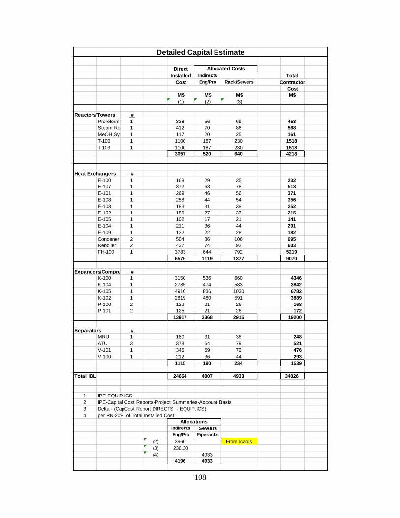
108
Detailed Capital Estimate
Design Direct
P, psig T, F MOC Installed Indirects Total
Packing Head Motor Comments s/t s/t s/t Cost Eng/Pro Rack/Sewers Contractor
No. of Diam Height Tan-Tan Area GPM ft HP Cost
Items ft ft ft ft2 (SCFM) (psi) (BHP) s/t = shell/tube HEx M$ M$ M$ M$
(1) (2) (3)
Reactors/Towers Reactors/Towers #
Prereformer 1 7 21 29 425 530 CS Prereformer 1 328 56 69 453
Steam Reformer 1 10 30 41 Refractory Lining 45 1150 CS Steam Reformer1 412 70 86 568
MeOH Synth 1 2 4 7 1102 570 CS MeOH Synth 1 117 20 25 161
T-100 1 11 122 40 trays 18 300 CS T-100 1 1100 187 230 1518
T-103 1 11 122 40 trays 18 300 CS T-103 1 1100 187 230 1518
3057 520 640 4218
Heat Exchangers Heat Exchangers #
E-100 1 748 425/45 550/1150 CS E-100 1 168 29 35 232
E-107 1 14077 425/45 570/1113 CS E-107 1 372 63 78 513
E-101 1 7757 45/70 690/160 CS E-101 1 269 46 56 371
E-108 1 6670 45/70 330/160 CS E-108 1 258 44 54 356
E-103 1 2564 1030/70 745/160 CS E-103 1 183 31 38 252
E-102 1 1003 1030/45 950/256 CS E-102 1 156 27 33 215
E-105 1 516 1030/70 657/160 CS E-105 1 102 17 21 141
E-104 1 4700 45/90 250/10 CS E-104 1 211 36 44 291
E-109 1 1181 45/70 230/160 CS E-109 1 132 22 28 182
Condenser 2 5880 40/70 225/160 CS Condener 2 504 86 106 695
Reboiler 2 5272 45/70 438/275 CS Reboiler 2 437 74 92 603
FH-100 1 6903 45 1400 CS FH-100 1 3783 644 792 5219
6575 1119 1377 9070
Expanders/Compressors
K-100 1 4413 0 530 425 CS Expanders/Compressors #
K-104 1 11481 18851 195 746 CS K-100 1 3150 536 660 4346
K-105 1 2806 254838 1102 941 CS K-104 1 2785 474 583 3842
K-102 1 1185 0 1102 570 CS K-105 1 4916 836 1030 6782
P-100 2 219 115 11 65 245 CS K-102 1 2819 480 591 3889
P-101 2 214 306 23 115 225 CS P-100 2 122 21 26 168
P-101 2 125 21 26 172
Separators 13917 2368 2915 19200
MRU 1 4 11 Mercury 425 200 SS304
ATU 3 2 8 SS lining 425 200 CS/SS304 Separators #
V-101 1 11 35 45 210 CS MRU 1 180 31 38 248
V-100 1 7 30 45 80 CS ATU 3 378 64 79 521
V-101 1 345 59 72 476
V-100 1 212 36 44 293
1115 190 234 1539
Total IBL 24664 4007 4933 34026
Fill in what you know
P-Design = P-Operating + 30 psi or P-Operating * 1.10, whichever is larger
T-Design = T-Operating + 50F (good enough for now…in real life, must be analyzed for different situations) 1 IPE-EQUIP.ICS
2 IPE-Capital Cost Reports-Project Summaries-Account Basis
3 Delta - (CapCost Report DIRECTS - EQUIP.ICS)
4 per RN-20% of Total Installed Cost
Indirects Sewers
Eng/Pro Piperacks
(2) 3960 From Icarus
(3) 236.30
(4) 4933
4196 4933
MeOH Plant (LitLion Chemical)
Equipment List
Allocated Costs
Allocations

109
Detailed Energy Balance
Streams in m (lbm/h) T (F) P (psia) Cp (BTU/lbm-F) dh vap (BTU/lb) Heat Flow (BTU/hr)
1 4.93E+04 80 400 0.5409 446 2.13E+06
Streams out m (lbm/h) T (F) P (psia) Cp (BTU/lbm-F) dh vap (BTU/lb) Heat Flow (BTU/hr)
2 1.10E+01 80 400 0.3149 162.8 2.77E+02
3 4.93E+04 80 400 0.541 226.5 2.13E+06
Overall Flow -195
MRU
Streams in m (lbm/h) T (F) P (psia) Cp (BTU/lbm-F) dh vap (BTU/lb) Heat Flow (BTU/hr)
3 4.93E+04 80 400 0.541 226.5 2.13E+06
4 1.24E+05 40 400 0.8371 587 4.16E+06
Streams out m (lbm/h) T (F) P (psia) Cp (BTU/lbm-F) dh vap (BTU/lb) Heat Flow (BTU/hr)
5 1.26E+05 52.43 400 0.838 596.3 5.52E+06
6 4.79E+04 72 400 0.5477 207.6 1.89E+06
Overall Flow -1.12E+06
Requires 1.12E+06 Btu/hr
ATU
Streams in m (lbm/h) T (F) P (psia) Cp (BTU/lbm-F) dh vap (BTU/lb)
6 4.79E+04 72 400 0.5477 207.6 Heat Flow (BTU/hr)
10 6.05E+05 1100 30 0.5762 1502
1.27E+07 6
Streams out m (lbm/h) T (F) P (psia) Cp (BTU/lbm-F) dh vap (BTU/lb) -1.27E+07 10
6_1 4.79E+04 500 400 0.6899 207.6
10_1 6.05E+05 1063.556 30 0.5731 1502
E-100
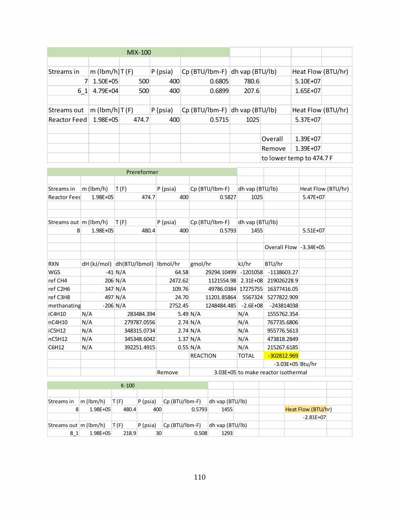
110
Streams in m (lbm/h)T (F) P (psia) Cp (BTU/lbm-F) dh vap (BTU/lb) Heat Flow (BTU/hr)
7 1.50E+05 500 400 0.6805 780.6 5.10E+07
6_1 4.79E+04 500 400 0.6899 207.6 1.65E+07
Streams out m (lbm/h)T (F) P (psia) Cp (BTU/lbm-F) dh vap (BTU/lb) Heat Flow (BTU/hr)
Reactor Feed 1.98E+05 474.7 400 0.5715 1025 5.37E+07
Overall 1.39E+07
Remove 1.39E+07
to lower temp to 474.7 F
MIX-100
Streams in m (lbm/h) T (F) P (psia) Cp (BTU/lbm-F) dh vap (BTU/lb) Heat Flow (BTU/hr)
Reactor Feed 1.98E+05 474.7 400 0.5827 1025 5.47E+07
Streams out m (lbm/h) T (F) P (psia) Cp (BTU/lbm-F) dh vap (BTU/lb)
8 1.98E+05 480.4 400 0.5793 1455 5.51E+07
Overall Flow -3.34E+05
RXN dH (kJ/mol) dh(BTU/lbmol) lbmol/hr gmol/hr kJ/hr BTU/hr
WGS -41 N/A 64.58 29294.10499 -1201058 -1138603.27
ref CH4 206 N/A 2472.62 1121554.98 2.31E+08 219026228.9
ref C2H6 347 N/A 109.76 49786.0384 17275755 16377416.05
ref C3H8 497 N/A 24.70 11201.85864 5567324 5277822.909
methanating -206 N/A 2752.45 1248484.485 -2.6E+08 -243814038
iC4H10 N/A 283484.394 5.49 N/A N/A 1555762.354
nC4H10 N/A 279787.0556 2.74 N/A N/A 767735.6806
iC5H12 N/A 348315.0734 2.74 N/A N/A 955776.5613
nC5H12 N/A 345348.6042 1.37 N/A N/A 473818.2849
C6H12 N/A 392251.4915 0.55 N/A N/A 215267.6185
REACTION TOTAL -302812.969
-3.03E+05 Btu/hr
Remove 3.03E+05 to make reactor isothermal
Prereformer
Streams in m (lbm/h) T (F) P (psia) Cp (BTU/lbm-F) dh vap (BTU/lb)
8 1.98E+05 480.4 400 0.5793 1455 Heat Flow (BTU/hr)
-2.81E+07
Streams out m (lbm/h) T (F) P (psia) Cp (BTU/lbm-F) dh vap (BTU/lb)
8_1 1.98E+05 218.9 30 0.508 1293
K-100

111
Streams in m (lbm/h)T (F) P (psia) Cp (BTU/lbm-F) dh vap (BTU/lb) vapor flow Heat Flow (BTU/hr)
13_1 4.07E+05 160 30 1.001 951.9 0 6.52E+07
8_1 1.98E+05 218.9 30 0.508 1293 1.21E+05 2.20E+07
Streams out m (lbm/h)T (F) P (psia) Cp (BTU/lbm-F) dh vap (BTU/lb) Heat Flow (BTU/hr)
9 6.05E+05 216.8 30 0.7587 1455 1.15E+05 9.95E+07
Overall -4.16E+06
Add -4.16E+06
To heat to 228.7
MIX-101
Streams in m (lbm/h) T (F) P (psia) Cp (BTU/lbm-F) dh vap (BTU/lb)
9 6.05E+05 216.8 30 0.9126 -786 Heat Flow (BTU/hr)
10_1 6.05E+05 1063 30 0.5731 1502
1.49E+08 9
Streams out m (lbm/h) T (F) P (psia) Cp (BTU/lbm-F) dh vap (BTU/lb) -1.49E+08 10
9_1 6.05E+05 520 30 0.4966 -786
10_2 6.05E+05 637.1928 30 0.5835 1502
The component that is condensing in stream 10 is only H2O
There are 485370 lb/hr condensing flow
dHvap for H2O 40.66 BTU/lb 19735144.2 BTU/hr
E-107

112
Streams in m (lbm/h)T (F) P (psia) Cp (BTU/lbm-F) dh vap (BTU/lb)
9_1 6.05E+05 520 30 0.4966 1455 Heat Flow (BTU/hr)
1.86E+08
Streams out m (lbm/h)T (F) P (psia) Cp (BTU/lbm-F) dh vap (BTU/lb)
9_2 6.05E+05 1100 30 0.5606 1455
BURNING METHANE BURNING H2
dHcomb dH comb
CH4 + O2 -> CO2 + H20 -802.34 kJ/gmol LHV 2 H2+O2 -> 2 H2O -244 kJ/gmol LHV
-760.4714918 Btu/gmol -231.267 Btu/gmol
-344942.264 Btu/lbmol -104901 Btu/lbmol
To heat sufficiently, burn:
537.9034353 lbmol/hr CH4 1768.776 lbmol/hr H2
8629.315861 lbm/hr CH4 3565.641 lbm/hr H2
Have 3868.09 lbm/hr available 5191.46 lbm/hr available
241.1151 lbmol/hr available 2575.28 lbmol/hr available
Possible Heat: -3.53E+08 Btu/hr total --> 15006.18 lbm/hr
-1.68E+08 Btu/hr extra --> 7125.681 lbm/hr
7880.5 lbm/hr used in FH
Verifying that stream has dH comb > 8000 Btu/lbm
frac
CH4 -21501.8 Btu/lbm 0.257766427
H2 -52037.1 Btu/lbm 0.3459545
Mix -23544.9 Btu/lbm (HYSYS = -24779.86 Btu/lbm)
FH-100
Streams in m (lbm/h) T (F) P (psia) Cp (BTU/lbm-F) dh vap (BTU/lb) Heat Flow (BTU/hr)
9_2 6.05E+05 1100 30 0.6116 1455 4.07E+08
Streams out m (lbm/h) T (F) P (psia) Cp (BTU/lbm-F) dh vap (BTU/lb) Heat Flow (BTU/hr)
10 6.05E+05 1100 30 0.6409 -1003 4.27E+08
RXN dH (kJ/mol) lbmol/hr gmol/hr kJ/hr BTU/hr
ref CH4 206 2449.68 1111151 228897148.6 2.17E+08
ref C2H6 347 0.00 0 0 0
ref C3H8 497 0.00 0 0 0
WGS -41 123.24 55900.77 -2291931.585 -2172751
Total 2.15E+08
Add 2.15E+08 BTU/hr to maintain isothermal in reformer
Reformer

113
Streams in m (lbm/h) T (F) P (psia) Cp (BTU/lbm-F) dh vap (BTU/lb)
10_2 6.05E+05 637.1928 30 0.5835 -1014
CW1 5.93E+06 90 70 0.998 908.1 Heat Flow (BTU/hr)
-1.18E+08 10
Streams out m (lbm/h) T (F) P (psia) Cp (BTU/lbm-F) dh vap (BTU/lb) 1.18E+08 CW
10_3 6.05E+05 280 30 0.51092 -1014
CW2 5.93E+06 110 70 0.9982 908.1
E-101
Streams in m (lbm/h) T (F) P (psia) Cp (BTU/lbm-F) dh vap (BTU/lb)
10_3 6.05E+05 280 30 0.51092 1502 Heat Flow (BTU/hr)
CW3 1.67E+06 90 70 0.998 908.1 -3.33E+07 10
3.33E+07 CW
Streams out m (lbm/h) T (F) P (psia) Cp (BTU/lbm-F) dh vap (BTU/lb)
10_4 6.05E+05 160 30 0.9287 1502
CW4 1.67E+06 110 70 0.9982 908.1
The component that is condensing in stream 10 is only H2O
There are 466162 lb/hr condensing flow
dHvap for H2O 40.66 BTU/lb 18954146.92 BTU/hr
E-108
Streams inm (lbm/h)T (F) P (psia) Cp (BTU/lbm-F)dh vap (BTU/lb)
10_4 6.05E+05 160 30 0.9287 1502 Heat Flow (BTU/hr)
3.86E+04
Streams outm (lbm/h)T (F) P (psia) Cp (BTU/lbm-F)dh vap (BTU/lb)
11 4.71E+05 160 30 1.001 951.9
14 1.34E+05 160 30 0.6724 948.9
V-101
Streams inm (lbm/h) T (F) P (psia) Cp (BTU/lbm-F) dh vap (BTU/lb) Heat Flow (BTU/hr)
11 4.71E+05 160 30 1.001 951.9 7.55E+07
Streams outm (lbm/h) T (F) P (psia) Cp (BTU/lbm-F) dh vap (BTU/lb) Heat Flow (BTU/hr)
13 4.07E+05 160 30 1.001 951.9 6.52E+07
12 6.40E+04 160 30 1.001 951.9 1.02E+07
Overall 0.00E+00
TEE-100

114
Streams in m (lbm/h) T (F) P (psia) Cp (BTU/lbm-F) dh vap (BTU/lb) Heat Flow (BTU/hr)
14 1.34E+05 160 30 0.6472 947 4.86E+07
Streams out m (lbm/h) T (F) P (psia) Cp (BTU/lbm-F) dh vap (BTU/lb)
14_1 1.34E+05 695.4077 180 0.7075 1850
Calculate T2
T1 619.67 R T2 1155.077685 R
k 1.385 695.4076848 F
np 0.79981
n/n-1 0.34755547
K-104
Streams in m (lbm/h) T (F) P (psia) Cp (BTU/lbm-F) dh vap (BTU/lb) Heat Flow (BTU/hr)
14_1 1.34E+05 695 180 0.71424 977 -3.88E+07 14
CW5 1.94E+06 90 70 0.998 908.1 3.88E+07 CW
Streams out m (lbm/h) T (F) P (psia) Cp (BTU/lbm-F) dh vap (BTU/lb)
14_2 1.34E+05 280 180 0.6829 977
CW6 1.94E+06 110 70 0.9982 908.1
E-103
Streams in m (lbm/h) T (F) P (psia) Cp (BTU/lbm-F) dh vap (BTU/lb) Heat Flow (BTU/hr)
14_2 1.34E+05 280 180 0.6829 1185 5.81E+07
Streams out m (lbm/h) T (F) P (psia) Cp (BTU/lbm-F) dh vap (BTU/lb)
14_3 1.34E+05 891.9 1015 0.735 1255
Calculate T2
T1 739.67 R T2 1351.532281 R
k 1.385 891.8622809 F
np 0.79765
n/n-1 0.3484966
K-105

115
Streams in m (lbm/h) T (F) P (psia) Cp (BTU/lbm-F) dh vap (BTU/lb)
14_3 1.34E+05 891.8623 1015 0.735 1255 Heat Flow (BTU/hr)
18 1.19E+05 30 30 1.053 638.7 -2.73E+07 14
2.73E+07 18
Streams out m (lbm/h) T (F) P (psia) Cp (BTU/lbm-F) dh vap (BTU/lb)
14_4 1.34E+05 609.2688 1015 0.7096 1425
18_1 1.19E+05 206 30 0.9811 638.7
H2O vaporization
There are 3922 lb/hr condensing flow
dHvap for H2O 40.66 BTU/lb 159468.52 BTU/hr
CH3OH vaporization
There are 11674 lb/hr condensing flow
dHvap for CH3OH 504.498 BTU/lb 5889509.652 BTU/hr
E-102
Streams in m (lbm/h) T (F) P (psia) Cp (BTU/lbm-F) dh vap (BTU/lb) Heat Flow (BTU/hr)
14_4 1.34E+05 609.2688 1015 0.70959 1255 -1.04E+07 14
CW7 5.19E+05 90 70 0.998 908.1 1.04E+07 CW
Streams out m (lbm/h) T (F) P (psia) Cp (BTU/lbm-F) dh vap (BTU/lb)
14_5 1.34E+05 500 1015 0.7069 1425
CW8 5.19E+05 110 70 0.9982 908.1
E-105
Streams in m (lbm/h) T (F) P (psia) Cp (BTU/lbm-F) dh vap (BTU/lb) Heat Flow (BTU/hr)
14_5 1.35E+05 500 1015 0.7069 1425 4.78E+07
Streams out m (lbm/h) T (F) P (psia) Cp (BTU/lbm-F) dh vap (BTU/lb) Heat Flow (BTU/hr)
16 1.34E+05 520 1015 0.6401 -800.9 4.46E+07
Overall 3.26E+06
RXN dH (kJ/mol) dH (BTU/lbmol) lbmol/hr gmol/hr kJ/hr BTU/hr
WGS -41 N/A 1871.29 848800.5028 -34800820.6 -3.3E+07
CO to MeOH -91 N/A 430.84 195424.2338 -17783605.3 -1.7E+07
CO2 to MeOH -49.43 N/A 2050.26 929976.662 -45968746.4 -4.4E+07
Ammonia -92 N/A 1.72 779.5305691 -71716.8124 -67987.5
Methyl Form N/A -49802.2885 0.20 91.7475136 N/A -10073.5
Ethanol N/A -109529.781 0.57 260.3785477 N/A -62874.4
TOTAL -9.36E+07
MeOH Synthesis

116
Streams in m (lbm/h) T (F) P (psia) Cp (BTU/lbm-F) dh vap (BTU/lb) Heat Flow (BTU/hr)
16 1.34E+05 520 1015 0.6401 -800.9 -3.89E+07
Streams out m (lbm/h) T (F) P (psia) Cp (BTU/lbm-F) dh vap (BTU/lb)
16_1 1.34E+05 185 30 1.093 -800.9
K-102
Streams in m (lbm/h) T (F) P (psia) Cp (BTU/lbm-F) dh vap (BTU/lb)
16_1 1.34E+05 185 30 1.093 -8.01E+02 Heat Flow (BTU/hr)
R1 N/A -44 63 0.559 1.74E+02
-2.14E+07 16
Streams out m (lbm/h) T (F) P (psia) Cp (BTU/lbm-F) dh vap (BTU/lb) 70000000 R
16_2 1.34E+05 30 30 0.9733 -5.44E+02
R2 N/A -44 63 0.559 1.74E+02 Suficient refrigeration from unit is
2.14E+07 Btu/hr
E-104
Streams in m (lbm/h) T (F) P (psia) Cp (BTU/lbm-F) dh vap (BTU/lb) Heat Flow (BTU/hr)
16_2 1.34E+05 30 30 1.087 1853 4.37E+06
Streams out m (lbm/h) T (F) P (psia) Cp (BTU/lbm-F) dh vap (BTU/lb) Heat Flow (BTU/hr)
17 1.50E+04 30 30 1.351 1283 6.08E+05
18 1.19E+05 30 30 1.053 638.7 3.76E+06
Overall 2.41E+03
V-100
Streams inm (lbm/h) T (F) P (psia) Cp (BTU/lbm-F) dh vap (BTU/lb) Heat Flow (BTU/hr)
18_1 1.19E+05 206.3 30 1.058 664.9 2.59E+07
Streams outm (lbm/h) T (F) P (psia) Cp (BTU/lbm-F) dh vap (BTU/lb) Heat Flow (BTU/hr)
19 5.94E+04 206.3 30 1.058 664.9 1.30E+07
20 5.94E+04 206.3 30 1.058 664.9 1.30E+07
Overall 0.00E+00
TEE-101

117
Streams inm (lbm/h) T (F) P (psia) Cp (BTU/lbm-F) dh vap (BTU/lb) Heat Flow (BTU/hr)
17 1.50E+04 30 30 1.351 1283 6.08E+05
Streams outm (lbm/h) T (F) P (psia) Cp (BTU/lbm-F) dh vap (BTU/lb) Heat Flow (BTU/hr)
17_1 7.40E+03 30 30 1.351 1283 3.00E+05
17_2 7.60E+03 30 30 1.351 1283 3.08E+05
Overall 0.00E+00
TEE-102
Streams in m (lbm/h)T (F) P (psia) Cp (BTU/lbm-F) dh vap (BTU/lb) Heat Flow (BTU/hr)
12 6.40E+04 160 30 1.001 951.9 1.02E+07
22 1.99E+04 238.5 29 1.011 954.5 4.80E+06
24 1.99E+04 238.5 29 1.011 954.5 4.80E+06
Streams out m (lbm/h)T (F) P (psia) Cp (BTU/lbm-F) dh vap (BTU/lb) Heat Flow (BTU/hr)
25 1.04E+05 192.8 29 1.004 954.1 2.01E+07
Overall -2.46E+05
MIX-103
Streams in m (lbm/h)T (F) P (psia) Cp (BTU/lbm-F) dh vap (BTU/lb) Heat Flow (BTU/hr)
21 3.96E+04 174.6 24.5 0.9565 482.1 6.61E+06
23 3.96E+04 174.6 24.5 0.9565 482.1 6.61E+06
Streams out m (lbm/h)T (F) P (psia) Cp (BTU/lbm-F) dh vap (BTU/lb) Heat Flow (BTU/hr)
26 7.91E+04 174.6 24.5 0.9565 482 1.32E+07
Overall 0.00E+00
MIX-104
Streams in m (lbm/h)T (F) P (psia) Cp (BTU/lbm-F) dh vap (BTU/lb) Heat Flow (BTU/hr)
25 1.04E+05 192.8 29 1.004 954.1 2.01E+07
Streams out m (lbm/h)T (F) P (psia) Cp (BTU/lbm-F) dh vap (BTU/lb) Heat Flow (BTU/hr)
25_1 1.04E+05 195.8 50 1.004 928.8 2.04E+07
Overall -3.12E+05
P-100

118
Streams in m (lbm/h)T (F) P (psia) Cp (BTU/lbm-F) dh vap (BTU/lb) Heat Flow (BTU/hr)
26 7.91E+04 174.6 24.5 0.9565 482 1.32E+07
Streams out m (lbm/h)T (F) P (psia) Cp (BTU/lbm-F) dh vap (BTU/lb) Heat Flow (BTU/hr)
26_1 7.91E+04 175 100 0.9558 423.6 1.32E+07
Overall -2.06E+04
P-101
Streams in m (lbm/h) T (F) P (psia) Cp (BTU/lbm-F) dh vap (BTU/lb) Heat Flow (BTU/hr)
26_1 7.91E+04 172 100 1.0002 423.6 -4.02E+06 14
CW9 2.02E+05 90 70 0.998 908.1 4.02E+06 CW
Streams out m (lbm/h) T (F) P (psia) Cp (BTU/lbm-F) dh vap (BTU/lb)
26_2 7.91E+04 120 100 0.9555 423.6
CW10 2.02E+05 110 70 0.9982 908.1
E-109
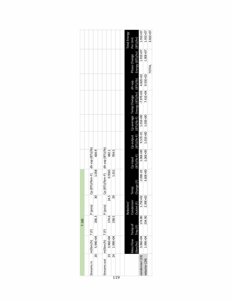
119
Stre
ams
inm
(lb
m/h
)T
(F)
P (
psi
a)C
p (
BTU
/lb
m-F
)d
h v
ap (
BTU
/lb
)
205.
94E+
0420
6.3
301.
058
664.
9
Stre
ams
ou
tm
(lb
m/h
)T
(F)
P (
psi
a)C
p (
BTU
/lb
m-F
)d
h v
ap (
BTU
/lb
)
233.
96E+
0417
4.6
24.5
0.95
6548
2.1
241.
99E+
0423
8.5
291.
011
954.
5
Mas
s Fl
ow
(lb
m/h
r)
Tem
p o
f
Tray
(F)
Re
bo
ile
r/
Co
nd
en
ser
Ou
tle
t (F
)
Tem
p
Ch
ange
(F)
Cp
inp
ut
(BTU
/lb
-F)
Cp
ou
tpu
t
(BTU
/lb
-F)
Cp
ave
rage
(BTU
/lb
-F)
Tem
p C
han
ge
Ene
rgy
(BTU
/hr)
dh
vap
(BTU
/lb
)
Ph
ase
Ch
ange
Ene
rgy
(BTU
/hr)
Tota
l En
erg
y
Pe
r U
nit
(BTU
/hr)
con
de
nse
r (2
3)3.
96E+
0417
4.80
1.75
E+02
-2.0
0E-0
11.
06E+
009.
57E-
011.
01E+
00-7
.97E
+03
4.82
E+02
1.91
E+07
1.91
E+07
reb
oil
er
(24)
1.99
E+04
234.
902.
39E+
023.
60E+
001.
06E+
001.
01E+
001.
03E+
007.
41E+
049.
55E+
021.
90E+
071.
91E+
07
TOTA
L3.
81E+
07
T-10
0

120
Stre
ams
inm
(lb
m/h
)T
(F)
P (
psi
a)C
p (
BTU
/lb
m-F
)d
h v
ap (
BTU
/lb
)
195.
94E+
0420
6.3
301.
058
664.
9
Stre
ams
ou
tm
(lb
m/h
)T
(F)
P (
psi
a)C
p (
BTU
/lb
m-F
)d
h v
ap (
BTU
/lb
)
213.
96E+
0417
4.6
24.5
0.95
6548
2.1
221.
99E+
0423
8.5
291.
011
954.
5
Mas
s Fl
ow
(lb
m/h
r)
Tem
p o
f
Tray
(F)
Re
bo
ile
r/
Co
nd
en
ser
Ou
tle
t (F
)
Tem
p
Ch
ange
(F)
Cp
inp
ut
(BTU
/lb
-F)
Cp
ou
tpu
t
(BTU
/lb
-F)
Cp
ave
rage
(BTU
/lb
-F)
Tem
p C
han
ge
Ene
rgy
(BTU
/hr)
dh
vap
(BTU
/lb
)
Ph
ase
Ch
ange
Ene
rgy
(BTU
/hr)
Tota
l En
erg
y
Pe
r U
nit
(BTU
/hr)
con
de
nse
r (1
9)3.
96E+
0417
4.80
1.75
E+02
-2.0
0E-0
11.
06E+
009.
57E-
011.
01E+
00-7
.97E
+03
4.82
E+02
1.91
E+07
1.91
E+07
reb
oil
er
(20)
1.99
E+04
234.
902.
39E+
023.
60E+
001.
06E+
001.
01E+
001.
03E+
007.
41E+
049.
55E+
021.
90E+
071.
91E+
07
TOTA
L3.
81E+
07
T-10
3

121
Sizing and Specification Sheets
Compressors:
K-104
MW 10.69 K [Cp/Cv] 1.385
Z1 1 Efficiency 75 Pt Eff 79.972
Z2 1.002 Zavg 1.001
T1 160 F 619.67 R
P1 30 psia
T2 696 F 1155.67 R
P2 180 psia
T2 Calculated 1155.159 R
Polytropic Head
R 144.565
(n-1)/n 0.347595
Flow 133891.2 lbm/hr 2231.52 lbm/min
HP 222933.1
Power 18850.52 BHP 14056.84 kW
4.86E+07 Btu/hr 1.42E+04 kW DUTY

122
Expander
K-105
MW 10.69 K [Cp/Cv] 1.381
Z1 1.001 Efficiency 75 Pt Eff 79.757
Z2 1.012 Zavg 1.0065
T1 280 F 739.67 R
P1 180 psia
T2 891.9 F 1351.57 R
P2 1015 psia
T2 Calculated 1345.498 R
Polytropic Head
R 144.565
(n-1)/N 0.345909
Flow 133891.2 lbm/hr 2231.52 lbm/min
HP 254837.7
Power 21606.37 BHP 16111.87 kW
5.81E+07 Btu/hr 1.70E+04 kW DUTY

123
K-100
MW 17.72 K [Cp/Cv] 1.336
Z1 0.9446 Efficiency 75 Pt Eff 73.294
Z2 0.9902 Zavg 0.9674
T1 480.4 F 940.07 R
P1 400 psia
T2 218.9 F 678.57 R
P2 30 psia
T2 Calculated 386.5048 R
Polytropic Head
R 87.21219
(n-1)/N 0.343135
Flow 197855 lbm/hr 3297.583 lbm/min
HP -136109
NRG OUT Power -18556.7 BHP -13837.7 kW
-2.81E+07 Btu/hr -8.24E+03 kW DUTY

124
Reactor Sizing
K-102
MW 17.6 K [Cp/Cv] 1.383
Z1 0.9086 Efficiency 75 Pt Eff 72.216
Z2 0.9898 Zavg 0.9492
T1 520 F 979.67 R
P1 1015 psia
T2 185 F 644.67 R
P2 30 psia
T2 Calculated 253.8669 R
Polytropic Head
R 87.80682
(n-1)/N 0.38348
Flow 133891.3 lbm/hr 2677.826 lbm/min
HP -157747
NRG OUT Power -17725.4 BHP -13217.8 kW
-3.89E+07 Btu/hr -1.14E+04 kW DUTY
GHSV=SV
SV 14.29 GHSV L/D 3
57-4 53 LB/FT^3 V 4.81E+02 ft^3 Eps 0.35
Density 0.757440884 lb/ft^3 D 5.886243 ft dp 0.046280786 ft
mol flow 6867 lbmol/h L 17.65873 ft Vm 8.86E-02 ft/s
Mass flow 1.23E+05 lb/hr mu* 1.53E-02 Cp
ft^3/h 1.62E+05 ft^3/hr Dist 0.5 ft L 17.65873026 ft
Cat Volume 4.81E+02 ft^3 Cat support 0.5 ft mu 1.03E-05 lb/ft-s
Catalyst d 0.04265092 ft top 2.943122 rho 0.757440884 lb/ft^3
L 0.05577428 ft bottom 2.943122
V cat 7.96857E-05 ft^3 dP 0.015400798 psi
Cat mass 2.55E+04 lb cat L' 24.54497 ft
Cat Cost 6.71$ 1/lb cat
V 667.9268 ft^3
COST 170,892.96$ 7.41E+04
A 508.3148
Prereformer Sizing Pressure Drop

125
GHSV=SV
SV 14.29 GHSV L/D 3
57-4 53 LB/FT^3 V 9.17E+02 ft^3 Eps 0.35
Density 2.42E-02 lb/ft^3 D 7.301823 ft dp 0.046280786 ft
mol flow 1.31E+04 lbmol/h L 21.90547 ft Vm 3.44E+00 ft/s
Mass flow 2.32E+05 lb/hr mu* 2.63E-02 Cp
ft^3/h 9.61E+06 ft^3/hr Dist 0.5 ft L 21.90546852 ft
Cat Volume 9.17E+02 ft^3 Cat support 0.5 ft mu 1.77E-05 lb/ft-s
Catalyst d 0.04265092 ft top 3.650911 rho 2.42E-02 lb/ft^3
L 0.05577428 ft bottom 3.650911
V cat 7.96857E-05 ft^3 dP 0.972322875 psi
Cat mass 4.86E+04 lb cat L' 30.20729 ft
Cat Cost 6.71$ 1/lb cat
V 1264.923 ft^3
COST 326,214.61$
A 776.6853
Steam Reformer Pressure DropSizing
GHSV=SV
SV 717.15 GHSV lbmol/hr/ft^3 L/D 3
51-7 78 LB/FT^3 V 1.45E+01 ft^3 Eps 0.35
Density 1.25E+00 lb/ft^3 D 1.833557 ft dp 0.017492276 ft
mol flow 10416 lbmol/h L 5.500671 ft Vm 5.65E-01 ft/s
Mass flow 1.35E+05 lb/hr mu* 1.73E-02 Cp
ft^3/h 1.08E+05 ft^3/hr Dist 0.5 ft L 5.500670715 ft
Cat Volume 1.45E+01 ft^3 Cat support 0.5 ft mu 1.16E-05 lb/ft-s
Catalyst d 0.017716536 ft top 0.916778 rho 1.25E+00 lb/ft^3
L 0.017060368 ft bottom 0.916778
V cat 4.20568E-06 ft^3 dP 0.755380688 psi
Cat mass 1.13E+03 lb cat L' 8.334228 ft
Cat Cost 16.19$ 1/lb cat
V 22.00615 ft^3
COST 18,341.54$
A 53.28847
Methanol Reactor Sizing Pressure Drop
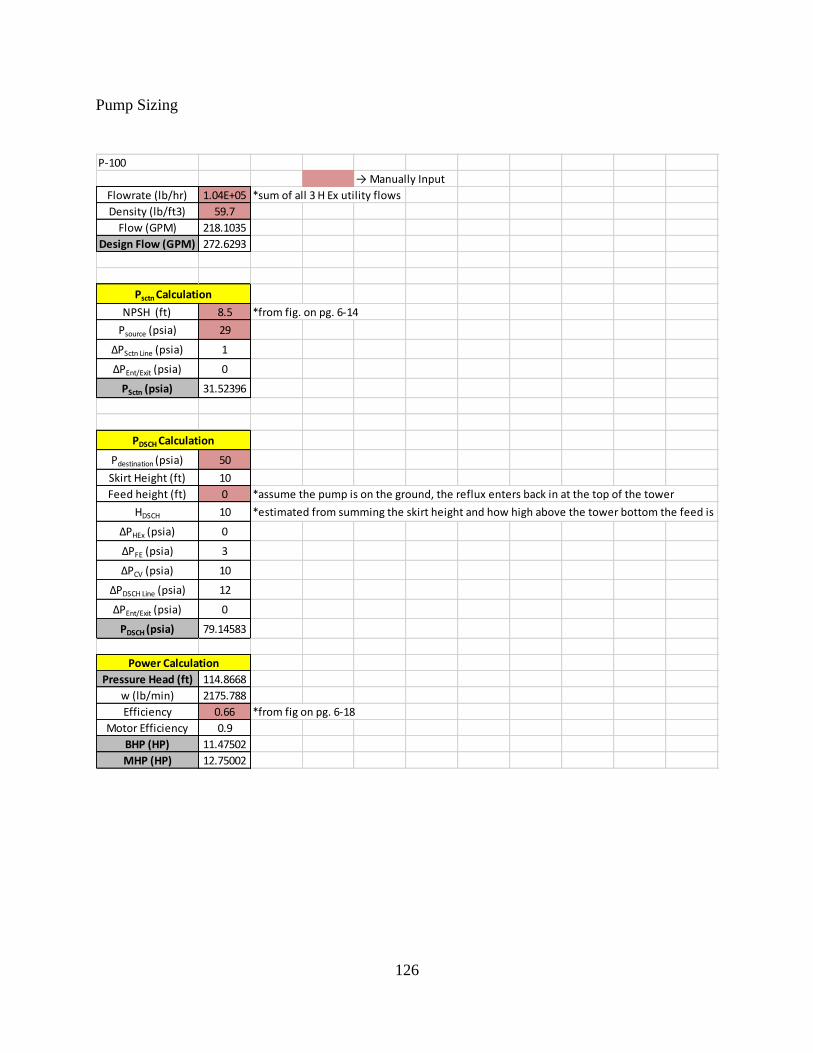
126
Pump Sizing
P-100
→ Manually Input
Flowrate (lb/hr) 1.04E+05 *sum of all 3 H Ex utility flows
Density (lb/ft3) 59.7
Flow (GPM) 218.1035
Design Flow (GPM) 272.6293
NPSH (ft) 8.5 *from fig. on pg. 6-14
Psource (psia) 29
ΔPSctn Line (psia) 1
ΔPEnt/Exit (psia) 0
PSctn (psia) 31.52396
Pdestination (psia) 50
Skirt Height (ft) 10
Feed height (ft) 0 *assume the pump is on the ground, the reflux enters back in at the top of the tower
HDSCH 10 *estimated from summing the skirt height and how high above the tower bottom the feed is
ΔPHEx (psia) 0
ΔPFE (psia) 3
ΔPCV (psia) 10
ΔPDSCH Line (psia) 12
ΔPEnt/Exit (psia) 0
PDSCH (psia) 79.14583
Pressure Head (ft) 114.8668
w (lb/min) 2175.788
Efficiency 0.66 *from fig on pg. 6-18
Motor Efficiency 0.9
BHP (HP) 11.47502
MHP (HP) 12.75002
Psctn Calculation
PDSCH Calculation
Power Calculation

127
P-101
→ Manually Input
Flowrate (lb/hr) 8.02E+04 *sum of all 3 H Ex utility flows
Density (lb/ft3) 45.33
Flow (GPM) 220.4497
Design Flow (GPM) 275.5622
NPSH (ft) 8.5 *from fig. on pg. 6-14
Psource (psia) 24.5
ΔPSctn Line (psia) 1
ΔPEnt/Exit (psia) 0
PSctn (psia) 26.17573
Pdestination (psia) 14.7
Skirt Height (ft) 10
Feed height (ft) 40 *assume the pump is on the ground, the reflux enters back in at the top of the tower
HDSCH 50 *estimated from summing the skirt height and how high above the tower bottom the feed is
ΔPHEx (psia) 0
ΔPFE (psia) 3
ΔPCV (psia) 10
ΔPDSCH Line (psia) 79.2
ΔPEnt/Exit (psia) 0
PDSCH (psia) 122.6396
Pressure Head (ft) 306.4371
w (lb/min) 1669.841
Efficiency 0.67 *from fig on pg. 6-18
Motor Efficiency 0.9
BHP (HP) 23.14343
MHP (HP) 25.71492
Psctn Calculation
PDSCH Calculation
Power Calculation

128
Heat Exchanger Sizing
Utility Dowtherm A Service (5-30) Vapor-vapor
IN Temp (F) 72.0 Mass Flow lbm/hr 232364 47855 U (5-30) 25.000 10 to 40
EXIT Temp (F) 500 Cp (Btu/(lb F)) 0.65426 0.548 Safety Factor 1.15
Utility Temp IN (F) 1100
Duty (MMBTU/hr) 11.22
11217971
Calculations
Utility Temp Out (F) 1026 Q-T Diagram
Area ft^3 676 Q 0 11 Q T
Utility Stream 1026 1100 Process Stream 0 72
11 500
Feed
E-100
0
200
400
600
800
1000
1200
0 2 4 6 8 10 12
T (F
)
Q (MMBTU/hr)
Utility Stream
Process Stream

129
Utility Dowtherm A Service (5-30) Vapor-vapor
IN Temp (F) 216.0 Mass Flow lbm/hr 232364 232364 U (5-30) 25.000
EXIT Temp (F) 550 Cp (Btu/(lb F)) 0.64087 0.759 Safety Factor 1.15
Utility Temp IN (F) 1016
Duty (MMBTU/hr) 58.883
Calculations 58883204
Utility Temp Out (F) 621 Q-T Diagram
Area ft^3 6233 Q 0 59 Q T
Utility Stream 621 1010 Process Stream 0 216
59 550
Feed
E-107
0
200
400
600
800
1000
1200
0 10 20 30 40 50 60 70
T (F
)
Q (MMBTU/hr)
Process Stream
Utility Stream
Utility Dowtherm A Service (5-30) Vapor-Liquid
IN Temp (F) 621.0 Mass Flow lbm/hr 232364 U (5-30) 50.000
EXIT Temp (F) 238 Cp (Btu/(lb F)) 0.64087 Safety Factor 1.15
Utility Temp IN (F) 90
Duty (MMBTU/hr) 57.079
Calculations
Utility Temp Out (F) 110 Q-T Diagram
Area ft^3 4485 Q 0 57 Q T
Utility Stream 110 90 Process Stream 0 621
57 238
Feed
E-101
0
100
200
300
400
500
600
700
0 10 20 30 40 50 60
T (F
)
Q (MMBTU/hr)
Utility Stream
Process Stream

130
Utility Dowtherm A Service (5-30) Vapor-Liquid
IN Temp (F) 652.0 Mass Flow lbm/hr 112317 U (5-30) 50.000
EXIT Temp (F) 280 Cp (Btu/(lb F)) 0.70754 Safety Factor 1.15
Utility Temp IN (F) 90
Duty (MMBTU/hr) 29.563
Calculations
Utility Temp Out (F) 110 Q-T Diagram
Area ft^3 2025 Q 0 30 Q T
Utility Stream 110 90 Process Stream 0 652
30 280
Feed
E-103
0
100
200
300
400
500
600
700
0 5 10 15 20 25 30 35
T (F
)
Q (MMBTU/hr)
Utility Stream
Process Stream
Utility Dowtherm A Service (5-30) Vapor-Liquid
IN Temp (F) 280.0 Mass Flow lbm/hr 232364 U (5-30) 50.000
EXIT Temp (F) 160 Cp (Btu/(lb F)) 0.64087 Safety Factor 1.15
Utility Temp IN (F) 90
Duty (MMBTU/hr) 21.736 The component that is vaporizing in stream 10 is only H2O
There are 95090 lb/hr vaporizing flow
Calculations dHvap for H2O 41 BTU/lb 3866359 BTU/hr
Utility Temp Out (F) 110 Q-T Diagram
Area ft^3 4436 Q 0 22 Q T
Utility Stream 110 90 Process Stream 0 280
22 160
Feed
E-108
0
50
100
150
200
250
300
0 5 10 15 20 25
T (F
)
Q (MMBTU/hr)
Utility Stream
Process Stream

131
Utility Dowtherm A Service (5-30) Vapor-Liquid
IN Temp (F) 30.0 Mass Flow lbm/hr 1.16E+05 112317 U (5-30) 50.000
EXIT Temp (F) 206 Cp (Btu/(lb F)) 1.0547 0.735 Safety Factor 1.15
Utility Temp IN (F) 827
Duty (MMBTU/hr) 22
Calculations 21534005
Utility Temp Out (F) 566 Q-T Diagram
Area ft^3 858 Q 0 22 Q T
Utility Stream 566 827 Process Stream 0 30
22 206
Feed
E-102
0
100
200
300
400
500
600
700
800
900
0 5 10 15 20 25
T (F
)
Q (MMBTU/hr)
Utility Stream
Process Stream
Utility Dowtherm A Service (5-30) Vapor-Liquid
IN Temp (F) 565.8 Mass Flow lbm/hr 115814 U (5-30) 50.000 dh Vapor Flow
EXIT Temp (F) 500 Cp (Btu/(lb F)) 1.05466 Safety Factor 1.15 908 6343
Utility Temp IN (F) 90
Duty (MMBTU/hr) 13.791
Calculations
Utility Temp Out (F) 110 Q-T Diagram
Area ft^3 733 Q 0 14 Q T
Utility Stream 110 90 Process Stream 0 566
14 500
Feed
E-105
0
100
200
300
400
500
600
0 2 4 6 8 10 12 14 16
T (F
)
Q (MMBTU/hr)
Utility Stream
Process Stream

132
Molar Flowrate 13108.02 lbmole/hr
Cp 13.48 BTU/lbmole-F
ΔT 680 F
Q 120130316.26 BTU/hr 120 MMBTU/hr
σ 1.71E-09 Btu/(hr-ft2-R
4)
α 0.54
F 0.7
Tt 2660 R
Tg 1760 R
Ac 4560 ft2
Area needed 5016 ft3
Fired Heater (FH-100)
𝑄 = 𝐹𝜎𝛼𝐴𝑐(𝑇𝑡4 − 𝑇𝑔
4)
Utility Dowtherm A Service (5-30)Refrigerant
IN Temp (F) 197.2 Utility Temp IN (F) -44 U (5-30) 125.000
EXIT Temp (F) 30 Duty (MMBTU/hr) 70.000 Safety Factor 1.15
Calculations
Utility Temp Out (F) -44 Q-T Diagram
Area ft^3 4557 Q 0 70 Q T
Utility Stream -44 -44 Process Stream 0 197
70 30
E-104 Refrigeration
Feed
0
10
20
30
40
50
60
70
80
90
100
-150 -100 -50 0 50 100
Cost
of
Refrig
, $/M
MB
TU
Temperature, F
Cost of Refrigeration
Effect of Temperature Level
Total Cost
Power Cost
-100
-50
0
50
100
150
200
250
0 10 20 30 40 50 60 70 80
T (F
)
Q (MMBTU/hr)

133
Separator Sizing
MRU
Streams 1 3 2
Vapor Phase Fraction 1.0 1 0
Temperature (°F) 80 80 80
Pressure (psia) 400 400 400
Mass Flow (lb/hr) 49269 49258 11
Hg mass Absorbed (lb/hr) 11
Mass Flow of Hg x run time of absorbents (lb) 1849.43
Mercury Density (lb/ft^3) 843.60
Mass of Activated Carbon (lb) 6164.75
Activated Carbon Density (lb/ft^3) 125
Hg capacity in activated carbon 0.3
Volume of Activated Carbon (Ft^3) 49.32
L (Ft) 10.42
D (Ft) 3.47
L/D 3.00
Volume of vessel (Ft^3) 98.65
Hg absorption based on 7 days (ONLY BASED ON 1 COLUMN)
Mercury Removal Unit (MRU) - Sizing
ATT Streams
3 4 6 5
Vapor Phase Fraction 1.0 0.0 1.0 0.0
Temperature (F) 80 40 72 52
Pressure (psia) 400 400 400 400
Mass Flow (lb/hr) 49258 124245 47855 125648
Gas Flow (MMSCFD) 24.95 Sulfur Content 31557.31 lb S/day
Actual Gas Flow 618.5 CFM Circulation rate, MDEA 93.56 gpm
10.31 ft^3/s Gas Velocity 11.50 ft/s
% H2S in feed stream 1.5 L/D = 6 6
% CO2 in feed stream 1.5 Inner Diameter (D) 1.19 ft
Temperature 80 F Length (L) 7.15 ft
Pressure 385.3 psig Volume 7.98 ft^3
K (MMSCFD) 1.25 Retention Time 10 minutes
Gas Density 1.328 lbm/ft3
MDEA Density 62.428 lbm/ft3
Amine Flow Rate
1.04 g/cm^3
52190 lbm/hr
8.679221 lbm/gal
6013.212
100.2202 gpm
Properties Sizing and Calculations
In Out

134
V-100
16-2 18 17 Settling Velocity (u t ) 2.96E+00 m/s
Vapor Fraction 0.3941 0.0 1.0 Minimum vessel diameter (Dv)
Temperature [F] 30.0 30.0 30.0 1.314 m
Pressure [psia] 30.0 30.0 30.0 4.310 ft
Molar Flow [lbmole/hr] 6318 4857 1461 Archimedes Number (Ar) 176.86
Mass Flow [lb/hr] 133891 118885 15006 Reynolds Number (Re) 6.332
Drag Coefficient (Cd)
for Re > 1 3.790
Needed to size separator (Properties from hysys) for Re <1 5.879
Gas rate (Qg) 26.39 MMSCFD Actual vessel Diameter (d)
Actual Gas Flow (ACFM) 8488 CFM d2 7223
4.006 m^3/s d 7.082 ft
Gas z-factor (Z) 1.0
Gas density (ρg) 3.06E-02 lbm/ft^3
0.491 kg/m^3 L (for L/d = 3) 21.247 ft
Liquid rate (Std. Cond) 55.31 m^3/h L (for L/d = 5) 42.494 ft
Actual Liquid Flow Rate 0.017 m^3/s Volume 1 (from HYSYS) 836.900 ft3
Liquid Density 54.65 lbm/ft^3 Volume 2 (from HYSYS) 1674.000 ft3
875.41 kg/m^3
Operating pressure (P) 30 psia
Operating temperature (T) 30 F
490 R
Drop Diameter (dm) 300 um
Liquid Viscosity 0.01071 P
0.001071 kg/m-s
Gravity Constant (g) 9.81 m/s^2
Nozzle Parameters
16-2 18 17
Diameter [ft] 1.06235 1.06235 1.06235
Elevation (Base) [ft] 10.6235 21.247 0
Elevation (Ground) [ft] 10.6235 21.247 0
Ratio of Length/Diameter ~ 3-5 range
Assume Length/Diameter:
Streams Sizing and Calculations

135
V-101
Streams In
10-4 11 14 Settling Velocity (u t ) 2.48E+00 m/s
Vapor Phase Fraction 0.3252 0 1.0 Minimum vessel diameter (Dv):
Temperature [F] 160 160 160 3.335517 m
Pressure [psia] 30 30 30 10.943297 ft
Mass Flow [lb/hr] 605195 471304 133891 Archimedes Number (Ar) 1606.43
Reynolds Number (Re) 34.227392
Drag Coefficient (Cd):
for Re > 1 0.7011928
for Re <1 1.8278654
Gas rate (Qg) 113.1 MMSCFD Actual vessel Diameter (d):
Actual Gas Flow (ACFM) 4.60E+04 CFM d216108.735
21.685985 m^3/s d 10.576683 ft
Gas z-factor (Z) 1.00
Gas density (ρg) 4.82E-02 lbm/ft^3
7.72E-01 kg/m^3 L Length (L/d = 3) 31.730 ft 3
Liquid rate (Std. Cond) 42.51 m^3/h L Length (L/d = 5) 52.883 ft
Actual Liquid Flow Rate 6.03E-02 m^3/s Volume 1 (from HYSYS) 2788.000 ft3
Liquid Density 60.66 lbm/ft^3 Volume 2 (from HYSYS) 4646.000 ft3
971.68079 kg/m^3
Operating pressure (P) 30 psia
Operating temperature (T) 160 F
620 R
Drop Diameter (dm) 300 um
Liquid Viscosity 0.003944 P
0.0003944 kg/m-s
g 9.81 m/s^2
10-4 11 14
Diameter [ft] 1.5865 1.5865 1.5865
Elevation (Base) [ft] 15.865 31.73 0
Elevation (Ground) [ft] 15.865 31.73 0
Sizing and Calculations
Ratio of Height/Diameter ~ 3-5 range
Assume Length/Diameter:
Nozzle Parameters
Needed to size separator (properties from HYSYS)
Out

136
Distillation Sizing
1) Copy from Volume flow of Tower
Key Light Key Heavy
Net L
(ft^3/hr)
Net V
(ft^3/hr)
Liq Density
(lb/ft^3)
Vap Density
(lb/ft^3)
Net L
(ft^3/s)
Net V
(ft^3/s)
Total
(ft^3/s)
Liq Mass Flow
(lb/hr)
Vap Mass
Flow
(lb/hr)
Liquid flow
(m^3/hr)
Vapor flow
(m^3/hr)
Methyanol
K Value
Water
K Value
Light Viscosity
(cP)
1 3840 1784529 45.2 0.12 1.07 495.70 496.8 1.74E+05 2.11E+05 109 50532 1 1.00 0.49 0.27
2 3843 1783492 46.1 0.12 1.07 495.41 496.5 1.74E+05 2.12E+05 109 50503 2 1.00 0.47 0.27
feed 3 3845 1776351 46.1 0.12 1.07 493.43 494.5 1.74E+05 2.12E+05 109 50301 3 1.00 0.46 0.27
4 3847 1768931 46.1 0.12 1.07 491.37 492.4 1.74E+05 2.12E+05 109 50091 4 1.00 0.46 0.27
5 3849 1761558 46.1 0.12 1.07 489.32 490.4 1.74E+05 2.12E+05 109 49882 5 1.00 0.46 0.27
6 3851 1754249 46 0.12 1.07 487.29 488.4 1.74E+05 2.12E+05 109 49675 6 1.00 0.46 0.27
7 3853 1747005 46 0.12 1.07 485.28 486.3 1.74E+05 2.12E+05 109 49470 7 1.00 0.46 0.27
8 3855 1739824 46 0.12 1.07 483.28 484.4 1.74E+05 2.12E+05 109 49266 8 1.00 0.45 0.27
9 3856 1732708 46 0.12 1.07 481.31 482.4 1.74E+05 2.13E+05 109 49065 9 1.00 0.46 0.27
10 3857 1725658 46 0.12 1.07 479.35 480.4 1.74E+05 2.13E+05 109 48865 10 1.00 0.46 0.27
11 3858 1718676 46 0.12 1.07 477.41 478.5 1.74E+05 2.13E+05 109 48667 11 1.00 0.46 0.27
12 3856 1711767 45.9 0.12 1.07 475.49 476.6 1.74E+05 2.13E+05 109 48472 12 1.00 0.46 0.27
13 3852 1704941 45.9 0.12 1.07 473.59 474.7 1.74E+05 2.13E+05 109 48279 13 1.00 0.46 0.27
14 3844 1698214 45.9 0.13 1.07 471.73 472.8 1.74E+05 2.12E+05 109 48088 14 1.01 0.46 0.27
15 3827 1691619 45.9 0.13 1.06 469.89 471.0 1.73E+05 2.12E+05 108 47901 15 1.01 0.47 0.27
16 3798 1685207 45.9 0.13 1.05 468.11 469.2 1.72E+05 2.11E+05 108 47720 16 1.02 0.47 0.27
17 3749 1679062 45.9 0.13 1.04 466.41 467.4 1.70E+05 2.10E+05 106 47546 17 1.03 0.49 0.27
18 3674 1673276 45.8 0.12 1.02 464.80 465.8 1.67E+05 2.08E+05 104 47382 18 1.04 0.51 0.27
19 3572 1667863 45.8 0.12 0.99 463.30 464.3 1.63E+05 2.06E+05 101 47229 19 1.06 0.54 0.27
20 3450 1662568 45.8 0.12 0.96 461.82 462.8 1.59E+05 2.02E+05 98 47079 20 1.08 0.58 0.27
21 3321 1656752 45.8 0.12 0.92 460.21 461.1 1.54E+05 1.97E+05 94 46914 21 1.11 0.62 0.27
22 3196 1649666 45.8 0.12 0.89 458.24 459.1 1.50E+05 1.93E+05 91 46713 22 1.12 0.67 0.27
23 3085 1641037 45.8 0.11 0.86 455.84 456.7 1.46E+05 1.88E+05 87 46469 23 1.13 0.70 0.27
24 2989 1631282 45.9 0.11 0.83 453.13 454.0 1.42E+05 1.84E+05 85 46193 24 1.14 0.73 0.27
25 2909 1621102 45.9 0.11 0.81 450.31 451.1 1.39E+05 1.81E+05 82 45904 25 1.15 0.75 0.27
26 2843 1611051 46 0.11 0.79 447.51 448.3 1.37E+05 1.78E+05 80 45620 26 1.16 0.76 0.27
27 2787 1601406 46.2 0.11 0.77 444.83 445.6 1.35E+05 1.75E+05 79 45347 27 1.17 0.77 0.27
28 2740 1592231 46.4 0.11 0.76 442.29 443.0 1.33E+05 1.73E+05 78 45087 28 1.18 0.78 0.27
29 2696 1583539 46.8 0.11 0.75 439.87 440.6 1.31E+05 1.71E+05 76 44841 29 1.18 0.78 0.27
30 3710 1577473 47.2 0.11 1.03 438.19 439.2 1.81E+05 1.70E+05 105 44669 30 1.20 0.78 0.26
31 3672 1496690 47.8 0.11 1.02 415.75 416.8 1.80E+05 1.61E+05 104 42382 31 1.20 0.79 0.27
32 3642 1485375 48.4 0.11 1.01 412.60 413.6 1.79E+05 1.60E+05 103 42061 32 1.20 0.79 0.27
33 3608 1477976 49 0.11 1.00 410.55 411.6 1.78E+05 1.59E+05 102 41852 33 1.21 0.80 0.27
34 3568 1470550 49.8 0.11 0.99 408.49 409.5 1.76E+05 1.58E+05 101 41641 34 1.21 0.80 0.27
35 3520 1462753 50.8 0.11 0.98 406.32 407.3 1.74E+05 1.56E+05 100 41421 35 1.22 0.80 0.27
36 3460 1454420 52.8 0.11 0.96 404.01 405.0 1.72E+05 1.54E+05 98 41185 36 1.23 0.81 0.27
37 3381 1445315 59.2 0.11 0.94 401.48 402.4 1.69E+05 1.52E+05 96 40927 37 1.25 0.81 0.27
38 3273 1435008 59.2 0.10 0.91 398.61 399.5 1.65E+05 1.49E+05 93 40635 38 1.28 0.81 0.27
39 3108 1422443 59.2 0.10 0.86 395.12 396.0 1.59E+05 1.45E+05 88 40279 39 1.35 0.81 0.27
40 2281 1399364 59.2 0.10 0.63 388.71 389.3 1.28E+05 1.39E+05 65 39626 40 3.30 0.66 0.29
Distillation Column
K Values

137
T-100
2) Vapor and Liqud Flowrates
Max Stage 1
Vapor ACFS 495.7 Actual ft 3̂/s Largest from Total Column above
Liquid Flow 0.97 ft 3̂/s
Vapor Density 0.12 lb/ft 3̂
Liquid Density 47 lb/ft 3̂
Liquid Mass Flow 164133 lb/hr
Specific Gravity 0.75
V_Load 24.74 Actual ft 3̂/s
GPM 436.28 GPM
TS, inches TS
12 0.65
3) Correction Factors 15 0.75
18 0.84
Tray Spacing 18 inches 21 0.92
Tray Spacing Factor 0.75 24 1.00
System Non-foaming 27 1.06
System Factor 1.00 30 1.12
Flood 70 70 for new tower 36 1.15
Flood Factor 1.14 FF = 80/Flood System SF
Non Foaming 1.00
Absorbers 0.85
37.70 Actual ft^3/s Vacuum Towers 0.85
664.81 GPM Amine/Glycol/CO2/H2S 0.80
Amine/Glycol/CO2/H2S 0.60
4) Tower Diameter obtained using with Glitsch Method
Four Pass:
Vapor Load 18.85 Actual ft 3̂/s
Liquid Load 332 GPM
Diameter from 2 pass N/A feet
Diameter for 4 pass 12.3 feet
*round up to nearest half foot
N/A
N/A
12
5) Actual Stages and Length
Tray Type 4 pass
Tower Diameter 12.3 feet (chosen from above)
alpha 2 (avg K Light)/(avg K Heavy)
avg µ 0.27
Efficiency 56.12%
Theoretical Stages 40
Actual Trays 71
Number of Feeds 1
Liquid Level Time 15 min (feed to reboiler pump)
Bot Product 20997 lb/hr http://www.cbu.edu/~rprice/lectures/distill7.html#eff
Bot Product Density 58 lb/ft 3̂
Calc Liquid Level 0.8 feet (3 feet min)
Actual Liquid Level 3 feet
Tower Sizing:
Reflux 3.0 feet
Trays and Feed 108.4 feet
Reboiler 6.0 feet
Liquid Level 3.0 feet
Tower Bottom 0.5 feet
Manways 20 feet
Total Height 141 feet
Diameter 12 feet Max Diameter is 16 feet
Height 141 feet Max Height is 200 ft
L/D 12 Avoid L/D >30
Tower Diameter (4 pass)
Corrected Vapor Load
Corrected Liquid Load
Tower Diameter (1 pass)
Tower Diameter (2 pass)

138
1) Copy from Volume flow of Tower
Key Light Key Heavy
Net L
(ft^3/hr)
Net V
(ft^3/hr)
Liq Density
(lb/ft^3)
Vap Density
(lb/ft^3)
Net L
(ft^3/s)
Net V
(ft^3/s)
Total
(ft^3/s)
Liq Mass Flow
(lb/hr)
Vap Mass
Flow
(lb/hr)
Liquid flow
(m^3/hr)
Vapor flow
(m^3/hr)
Methyanol
K Value
Water
K Value
Light Viscosity
(cP)
1 3840 1784529 45.2 0.12 1.07 495.70 496.8 1.74E+05 2.11E+05 109 50532 1 1.00 0.49 0.27
2 3843 1783492 46.1 0.12 1.07 495.41 496.5 1.74E+05 2.12E+05 109 50503 2 1.00 0.47 0.27
feed 3 3845 1776351 46.1 0.12 1.07 493.43 494.5 1.74E+05 2.12E+05 109 50301 3 1.00 0.46 0.27
4 3847 1768931 46.1 0.12 1.07 491.37 492.4 1.74E+05 2.12E+05 109 50091 4 1.00 0.46 0.27
5 3849 1761558 46.1 0.12 1.07 489.32 490.4 1.74E+05 2.12E+05 109 49882 5 1.00 0.46 0.27
6 3851 1754249 46 0.12 1.07 487.29 488.4 1.74E+05 2.12E+05 109 49675 6 1.00 0.46 0.27
7 3853 1747005 46 0.12 1.07 485.28 486.3 1.74E+05 2.12E+05 109 49470 7 1.00 0.46 0.27
8 3855 1739824 46 0.12 1.07 483.28 484.4 1.74E+05 2.12E+05 109 49266 8 1.00 0.45 0.27
9 3856 1732708 46 0.12 1.07 481.31 482.4 1.74E+05 2.13E+05 109 49065 9 1.00 0.46 0.27
10 3857 1725658 46 0.12 1.07 479.35 480.4 1.74E+05 2.13E+05 109 48865 10 1.00 0.46 0.27
11 3858 1718676 46 0.12 1.07 477.41 478.5 1.74E+05 2.13E+05 109 48667 11 1.00 0.46 0.27
12 3856 1711767 45.9 0.12 1.07 475.49 476.6 1.74E+05 2.13E+05 109 48472 12 1.00 0.46 0.27
13 3852 1704941 45.9 0.12 1.07 473.59 474.7 1.74E+05 2.13E+05 109 48279 13 1.00 0.46 0.27
14 3844 1698214 45.9 0.13 1.07 471.73 472.8 1.74E+05 2.12E+05 109 48088 14 1.01 0.46 0.27
15 3827 1691619 45.9 0.13 1.06 469.89 471.0 1.73E+05 2.12E+05 108 47901 15 1.01 0.47 0.27
16 3798 1685207 45.9 0.13 1.05 468.11 469.2 1.72E+05 2.11E+05 108 47720 16 1.02 0.47 0.27
17 3749 1679062 45.9 0.13 1.04 466.41 467.4 1.70E+05 2.10E+05 106 47546 17 1.03 0.49 0.27
18 3674 1673276 45.8 0.12 1.02 464.80 465.8 1.67E+05 2.08E+05 104 47382 18 1.04 0.51 0.27
19 3572 1667863 45.8 0.12 0.99 463.30 464.3 1.63E+05 2.06E+05 101 47229 19 1.06 0.54 0.27
20 3450 1662568 45.8 0.12 0.96 461.82 462.8 1.59E+05 2.02E+05 98 47079 20 1.08 0.58 0.27
21 3321 1656752 45.8 0.12 0.92 460.21 461.1 1.54E+05 1.97E+05 94 46914 21 1.11 0.62 0.27
22 3196 1649666 45.8 0.12 0.89 458.24 459.1 1.50E+05 1.93E+05 91 46713 22 1.12 0.67 0.27
23 3085 1641037 45.8 0.11 0.86 455.84 456.7 1.46E+05 1.88E+05 87 46469 23 1.13 0.70 0.27
24 2989 1631282 45.9 0.11 0.83 453.13 454.0 1.42E+05 1.84E+05 85 46193 24 1.14 0.73 0.27
25 2909 1621102 45.9 0.11 0.81 450.31 451.1 1.39E+05 1.81E+05 82 45904 25 1.15 0.75 0.27
26 2843 1611051 46 0.11 0.79 447.51 448.3 1.37E+05 1.78E+05 80 45620 26 1.16 0.76 0.27
27 2787 1601406 46.2 0.11 0.77 444.83 445.6 1.35E+05 1.75E+05 79 45347 27 1.17 0.77 0.27
28 2740 1592231 46.4 0.11 0.76 442.29 443.0 1.33E+05 1.73E+05 78 45087 28 1.18 0.78 0.27
29 2696 1583539 46.8 0.11 0.75 439.87 440.6 1.31E+05 1.71E+05 76 44841 29 1.18 0.78 0.27
30 3710 1577473 47.2 0.11 1.03 438.19 439.2 1.81E+05 1.70E+05 105 44669 30 1.20 0.78 0.26
31 3672 1496690 47.8 0.11 1.02 415.75 416.8 1.80E+05 1.61E+05 104 42382 31 1.20 0.79 0.27
32 3642 1485375 48.4 0.11 1.01 412.60 413.6 1.79E+05 1.60E+05 103 42061 32 1.20 0.79 0.27
33 3608 1477976 49 0.11 1.00 410.55 411.6 1.78E+05 1.59E+05 102 41852 33 1.21 0.80 0.27
34 3568 1470550 49.8 0.11 0.99 408.49 409.5 1.76E+05 1.58E+05 101 41641 34 1.21 0.80 0.27
35 3520 1462753 50.8 0.11 0.98 406.32 407.3 1.74E+05 1.56E+05 100 41421 35 1.22 0.80 0.27
36 3460 1454420 52.8 0.11 0.96 404.01 405.0 1.72E+05 1.54E+05 98 41185 36 1.23 0.81 0.27
37 3381 1445315 59.2 0.11 0.94 401.48 402.4 1.69E+05 1.52E+05 96 40927 37 1.25 0.81 0.27
38 3273 1435008 59.2 0.10 0.91 398.61 399.5 1.65E+05 1.49E+05 93 40635 38 1.28 0.81 0.27
39 3108 1422443 59.2 0.10 0.86 395.12 396.0 1.59E+05 1.45E+05 88 40279 39 1.35 0.81 0.27
40 2281 1399364 59.2 0.10 0.63 388.71 389.3 1.28E+05 1.39E+05 65 39626 40 3.30 0.66 0.29
Distillation Column
K Values

139
T-103
2) Vapor and Liqud Flowrates
Max Stage 1
Vapor ACFS 495.7 Actual ft 3̂/s Largest from Total Column above
Liquid Flow 0.97 ft 3̂/s
Vapor Density 0.12 lb/ft 3̂
Liquid Density 47 lb/ft 3̂
Liquid Mass Flow 164133 lb/hr
Specific Gravity 0.75
V_Load 24.74 Actual ft 3̂/s
GPM 436.28 GPM
TS, inches TS
12 0.65
3) Correction Factors 15 0.75
18 0.84
Tray Spacing 18 inches 21 0.92
Tray Spacing Factor 0.75 24 1.00
System Non-foaming 27 1.06
System Factor 1.00 30 1.12
Flood 70 70 for new tower 36 1.15
Flood Factor 1.14 FF = 80/Flood System SF
Non Foaming 1.00
Absorbers 0.85
37.70 Actual ft^3/s Vacuum Towers 0.85
664.81 GPM Amine/Glycol/CO2/H2S 0.80
Amine/Glycol/CO2/H2S 0.60
4) Tower Diameter obtained using with Glitsch Method
Four Pass:
Vapor Load 18.85 Actual ft 3̂/s
Liquid Load 332 GPM
Diameter from 2 pass N/A feet
Diameter for 4 pass 12.3 feet
*round up to nearest half foot
N/A
N/A
12
5) Actual Stages and Length
Tray Type 4 pass
Tower Diameter 12.3 feet (chosen from above)
alpha 2 (avg K Light)/(avg K Heavy)
avg µ 0.27
Efficiency 56.12%
Theoretical Stages 40
Actual Trays 71
Number of Feeds 1
Liquid Level Time 15 min (feed to reboiler pump)
Bot Product 20997 lb/hr http://www.cbu.edu/~rprice/lectures/distill7.html#eff
Bot Product Density 58 lb/ft 3̂
Calc Liquid Level 0.8 feet (3 feet min)
Actual Liquid Level 3 feet
Tower Sizing:
Reflux 3.0 feet
Trays and Feed 108.4 feet
Reboiler 6.0 feet
Liquid Level 3.0 feet
Tower Bottom 0.5 feet
Manways 20 feet
Total Height 141 feet
Diameter 12 feet Max Diameter is 16 feet
Height 141 feet Max Height is 200 ft
L/D 12 Avoid L/D >30
Tower Diameter (4 pass)
Corrected Vapor Load
Corrected Liquid Load
Tower Diameter (1 pass)
Tower Diameter (2 pass)

140
Specification sheets
Identification: Date 4/15/2017
Item No.
No. required 2 by: AKH
Function:
Operation:
Purchased Cost M$ Equipment Cost Only
Installed Cost 7701 M$ Installation, not including InDirects or Escalation/Contingency
Type:
Stage 1 2 3 4
Material of construction CS CS Component lb/hr w t frac
Compression ratio 6 5.639 Methane 5084.46 0.038
Volumetric flowrate, ACFM 45969 9151 H2O 36099.27 0.272
Pressure, psia Ethane 0.033 0.000
Inlet 30 180 CO2 11089.648 0.083
Outlet 180 1015 Nitrogen 1160.159 0.009
Design Propane 0.001 0.000
Temperature, F i-Butane 0.003 0.000
Inlet 160 280 n-Butane 0.002 0.000
Outlet 696 891.9 i-Pentane 0.002 0.000
Design n-Pentane 0.001 0.000
Cyclohexane 0.000 0.000
Power: CO 64326.30 0.484
Driver (Turbine or Motor) Hydrogen 15176.29 0.114
Brake horsepower 18850 21606
Total Power consumption kW 132936.2 1.00
Intercooling/Aftercooling:
Outlet temperature, F 280
Outlet pressure, psia 180
Utility Flowrate, lb/hr 2E+06
Duty, MMBTU/hr 4E+07
Area (ft 3̂) 2025
Mean temp. difference
Auxilaries:
Safety factor
Corrosion allowance
Utilities:
Controls:
Insulation:
Tolerances:
Comments:
COMPRESSORS
K 104, K 105
Compress streams before the reformer
Feed Composition
Turbine
30169

141
Identification: Date 4/18/2017
Item No. T-100/T-103
No. required 2 by: Sarah Ramzy
Function:
Operation:
Purchased Cost M$ Equipment Cost Only (from IPE)
Installed Cost 1100 M$ Installation, not including InDirects or Escalation/Contingency
Design: Column
Material of construction A515 Height t-t 163 ft
Pressure Inner diameter 12 ft
Max Operating 15.3 psig Yield stress
Design 30 psig Joint efficiency
Temperature Corrosion allowance 1/8 inches
Max Operating 240 F Shell thickness 0.4673 inches
Design 400 F Shell weight
Head Information
Head type Joint efficiency
Material of construction Corrosion allowance
Inner diameter Head thickness
Thickness Head weight
Yield stress
Trays
Tray Type Sieve (valve, sieve, bubble)
No. of trays 40
Material of construction A285C
Tray spacing 18 inches
Diameter 9.2 ft
Tray thickness
Weir height 2 inches
Flooding factor 70 %
No. of passes 4
Downcomer width
Pressure drop/ tray 0.150 psi
Tray Design
Sieve Valve Bubble cap
Hole area Number Number
Hole diam. Size Size
Utilities: Reboiler MPS identify utilities used (e.g. LPS, MPS, CW, -40Fref, etc)
Condenser CW
Controls:
Insulation:
Tolerances:
Comments:
DISTILLATION COLUMNS
Distillation Tower
separate PG and EG into two prodcuct streams
Notes:-Not drawn to scale-40 trays

142
Identification: Date 3/30/2017
Item No.
No. required 1 by: AKH
Function:
Operation:
Purchased Cost M$ Equipment Cost Estimate
Installed Cost 3150 M$ Installation estimate, not including InDirects or Escalation/Contingency
Type:
Stage 1 2 3 4
Material of construction CS Component lb/hr w t frac
Compression ratio 0.075 Methane 44219.44 0.223
Volumetric flowrate, ACFM 4406 H2O 147554.1 0.746
Pressure, psia Ethane 0.033 2E-07
Inlet 400 CO2 4799.000 0.024
Outlet 30 Nitrogen 1160.160 0.006
Design Propane 0.001 6E-09
Temperature, F i-Butane 0.003 2E-08
Inlet 480.4 n-Butane 0.002 8E-09
Outlet 218.9 i-Pentane 0.002 1E-08
Design n-Pentane 0.001 5E-09
Cyclohexane4.62E-05 2E-10
Power: Hydrogen 136.853 7E-04
Driver (Turbine or Motor)
Brake horsepower -18557
Total Power consumption 197869.6 1.000
Intercooling/Aftercooling:
Outlet temperature, F N/A
Outlet pressure, psia
Utility Flowrate, lb/hr
Duty, MMBTU/hr
Area
Mean temp. difference
Auxilaries:
Safety factor
Corrosion allowance
Utilities:
Controls:
Insulation:
Tolerances:
Comments:
Expander
Expander K 100
Expands stream after prereformer
Feed Composition
Turbine
-13837.7

143
Identification: Date 3/30/2017
Item No.
No. required 1 by: BK
Function:
Operation:
Purchased Cost M$ Equipment Cost Only (from IPE)
Installed Cost 258 M$ Installation, not including InDirects or Escalation/Contingency
Type:
Heat exchanger type: ST BEM, etc 0.000 Duty 32.684 MMBTU/hr
Number of Shells 1 Outside area 6670 f t2
Heat Transfer Coef (U) 50 BTU/hr-ft2-F
Delta T-LM 113 F
Tube side: IN OUT Tubes:
Fluid handled Stream 10-4 Stream 10-5 Material of construction A 214
Flow rate, lb/hr Outer diameter
Liquid 0 131678
Vapor 597840 466162
Pressure, psig Thickness
Operating 15.3 15.3 Length, ft 20 from IPE
Design 15.3 No. of tubes 136 from IPE
Temperature, F Tube pattern Triangular from IPE
Operating 237.7 170 Pitch, in 1.25
Design 170 Pressure drop, psi 10
No. of Passes Fouling factor
Inlet nozzle ID Corrosion allowance
Outlet nozzle ID
Shell side: IN OUT Shell:
Fluid handled CW3 CW4 Material of construction A285C
Flow rate, lb/hr Length
Liquid N/A N/A
Vapor 0 0
Pressure, psig Inner diameter 18 from IPE
Operating 55 55 Thickness
Design 85 Total Weight
Temperature, F Shell
Operating 90 110 Full of water
Design 160 Bundle
No. of Passes Pressure drop 10
Inlet nozzle ID Fouling
Outlet nozzle ID Corrosion allowance 1/8 inches
Baffles:
Type Spacing
Material of construction Inner
Center
Outer
Utilities: Process
Controls:
Insulation:
Tolerances:
Comments: Provide Q-T Diagram
HEAT EXCHANGERS
E-108
Cooling process stream before compression
0
50
100
150
200
250
300
-35 -30 -25 -20 -15 -10 -5 0
T (F
)
Q (MMBTU/hr)
Utility Stream
Process Stream

144
Identification: Date 4/18/2017
Item No.
No. required 2 by: AKH
Function:
Operation:
Purchased Cost M$ Equipment Cost Only
Installed Cost 62.3 M$ Installation, not including InDirects or Escalation/Contingency
Type: Centrif Centrif or Recip
Material of construction
Volumetric flowrate, GPM 275.56
Required Head, ft 306.44
NPSH, ft 8.5
Pressure, psig
Operating 100
Design 115.3
Temperature, F
Operating
Design
Efficiency, % 75
Motor:
Driver (Turbine or Motor) Motor
Motor efficiency 90%
RPM 1800
Pump Horsepower 23.14 hP
Motor Horsepower 25.71 hP
Impeller diameter
Auxilaries:
Safety factor
Utilities:
Controls:
Insulation:
Tolerances:
Comments:
PUMPS
P-101
Pumps liquid from distillate to product stream
Carbon Steel

145
Identification: Date 3/30/2017
Item No.
No. required 1 by: BK
Function:
Operation:
Purchased Cost M$ Equipment Cost Only
Installed Cost 412 M$ Installation, not including InDirects or Escalation/Contingency
Design Data:
Vessel
Material of construction Height t-t 41 ft
Shape Inner diameter 30 ft
Configuration H H or V Thickness 0.25 in (from IPE)
Pressure, psig Volume 3185 ft3
Operating 15 % full N/A
Design 45
Temperature, F
Operating 1100
Design 1150
Heads
Material of construction Joint efficiency
Head type Corrosion allowance
Inner diameter Weight
Thickness
Stress values
Auxilaries
Platforms
Ladders
Inlet location
Outlet location
Mist separator
Utilities:
Controls:
Insulation:
Tolerances:
Comments: Provide attached sketch.
PRESSURE VESSELS
Steam Reformer
Reform remaining hydrocarbons
CS W/ refractory lining

146
ASPEN PEA Sizing Information
ITEM REPORT
Processing Date : Mon Apr 17 01:16:09 PM 2017
Version : Aspen Process Economic Analyzer 34.1.0(Build 3457)
List of Items :
Project: base case
Scenario: Base Case
Pre-reformer
Project : BASECASE
Scenario : BASECASE
Pre-reformer
Item Code: DTW PACKED
Internal Name : DTW PACKED #1#PFR
Sizing Data
Design Data
Summary Costs
Sizing Data
Description Value Units
Design Data
Parameter Value Units
Item type PACKED
Number of identical items 1
EQUIPMENT DESIGN DATA
Application ABSORB
ASME design basis D1NF
Liquid volume 8300.000 GALLONS

147
Design gauge pressure 425.000 PSIG
Design temperature 530.000 DEG F
Operating temperature 480.000 DEG F
GENERAL DESIGN DATA
Number of platforms 2
COLUMN DATA
Shell material CS
Diameter option ID
Vessel diameter 7.0000 FEET
Vessel tangent to tangent height 29.000 FEET
Head type ELLIP
MECHANICAL DESIGN DATA
Wind or seismic design W+S
Fluid volume 20.000 PERCENT
Weld efficiency 100.000 PERCENT
Base material thickness 1.3750 INCHES
Corrosion allowance 0.125000 INCHES
THICKNESSES REQUIRED
Circumferential stress thickness 1.1735 INCHES
Long tensile stress thickness 0.482159 INCHES
Long compressive stress thick 0.129581 INCHES
PACKING DATA
Number of distributor plates 4
Number of packed sections 2
Section height 10.500 FEET
Cross sectional area 38.485 SF
SECTION 1
Total packing height 21.000 FEET
Packing volume 808.175 CF

148
Packing volume per unit height 38.485 CF/FT
VESSEL SKIRT DATA
Skirt material CS
Skirt height 11.000 FEET
Skirt thickness 0.500000 INCHES
NOZZLE AND MANHOLE DATA
Nozzle ASA rating 300 CLASS
Nozzle material A285C
Nozzle A Quantity 1
Nozzle A Diameter 8.0000 IN DIAM
Nozzle A Location S
Nozzle B Quantity 1
Nozzle B Diameter 6.0000 IN DIAM
Nozzle B Location S
Nozzle C Quantity 1
Nozzle C Diameter 10.000 IN DIAM
Nozzle C Location S
Nozzle D Quantity 1
Nozzle D Diameter 12.000 IN DIAM
Nozzle D Location S
Nozzle E Quantity 5
Nozzle E Diameter 2.0000 IN DIAM
Nozzle E Location S
Number of manholes 3
Manhole diameter 30.000 INCHES
PROCESS DESIGN DATA
Molecular weight Overhead prod 30.000
WEIGHT DATA
Shell 36400 LBS

149
Trays and supports 2600 LBS
Heads 7400 LBS
Nozzles 590 LBS
Manholes and Large nozzles 5100 LBS
Skirt 5000 LBS
Base ring and lugs 770 LBS
Ladder clips 110 LBS
Platform clips 250 LBS
Fittings and miscellaneous 160 LBS
Total weight less packing 58400 LBS
VENDOR COST DATA
Material cost 65375 DOLLARS
Shop labor cost 23405 DOLLARS
Shop overhead cost 24106 DOLLARS
Office overhead cost 19191 DOLLARS
Profit 19823 DOLLARS
Total cost 151900 DOLLARS
Cost per unit weight 2.6010 USD/LBS
Cost per unit height or length 7233.333 USD/FT
Cost per unit volume 187.954 USD/CF
Cost per unit area 3947.043 USD/SF
Summary Costs
Item Material(USD) Manpower(USD) Manhours
Equipment&Setting 151900. 4355. 138
Piping 42440. 20064. 654
Civil 3741. 4125. 165
Structural Steel 14479. 2482. 86

150
Instrumentation 28440. 11870. 377
Electrical 1887. 1102. 37
Insulation 18818. 15190. 652
Paint 1185. 2707. 118
Subtotal 262890 61895 2227
Total material and manpower cost=USD 324800.
ITEM REPORT
Processing Date : Mon Apr 17 01:17:41 PM 2017
Version : Aspen Process Economic Analyzer 34.1.0(Build 3457)
List of Items :
Project : basecase
Scenario : Base Case
SMR
Project : BASECASE
Scenario : BASECASE
SMR
Item Code: DTW PACKED
Internal Name : DTW PACKED #2#PFR
Sizing Data
Design Data
Summary Costs
Sizing Data
Description Value Units
Design Data
Parameter Value Units
Item type PACKED

151
Number of identical items 1
EQUIPMENT DESIGN DATA
Application ABSORB
ASME design basis D1NF
Liquid volume 24100.00 GALLONS
Design gauge pressure 45.000 PSIG
Design temperature 650.000 DEG F
Operating temperature 600.000 DEG F
GENERAL DESIGN DATA
Number of platforms 3
COLUMN DATA
Shell material CS
Diameter option ID
Vessel diameter 10.000 FEET
Vessel tangent to tangent height 41.000 FEET
Head type HEMI
MECHANICAL DESIGN DATA
Wind or seismic design W+S
Fluid volume 20.000 PERCENT
Weld efficiency 85.000 PERCENT
Base material thickness 0.375000 INCHES
Corrosion allowance 0.125000 INCHES
THICKNESSES REQUIRED
Circumferential stress thickness 0.236368 INCHES
Long tensile stress thickness 0.087888 INCHES
Long compressive stress thick 0.181218 INCHES
PACKING DATA
Number of distributor plates 4
Number of packed sections 2

152
Section height 15.000 FEET
Cross sectional area 78.540 SF
SECTION 1
Total packing height 30.000 FEET
Packing volume 2356.194 CF
Packing volume per unit height 78.540 CF/FT
VESSEL SKIRT DATA
Skirt material CS
Skirt height 15.000 FEET
Skirt thickness 0.375000 INCHES
NOZZLE AND MANHOLE DATA
Nozzle ASA rating 150 CLASS
Nozzle material A285C
Nozzle A Quantity 1
Nozzle A Diameter 12.000 IN DIAM
Nozzle A Location S
Nozzle B Quantity 1
Nozzle B Diameter 10.000 IN DIAM
Nozzle B Location S
Nozzle C Quantity 1
Nozzle C Diameter 14.000 IN DIAM
Nozzle C Location S
Nozzle D Quantity 1
Nozzle D Diameter 16.000 IN DIAM
Nozzle D Location S
Nozzle E Quantity 6
Nozzle E Diameter 2.0000 IN DIAM
Nozzle E Location S
Number of manholes 4

153
Manhole diameter 36.000 INCHES
PROCESS DESIGN DATA
Molecular weight Overhead prod 30.000
WEIGHT DATA
Shell 19800 LBS
Trays and supports 4800 LBS
Heads 4000 LBS
Nozzles 770 LBS
Manholes and Large nozzles 4900 LBS
Skirt 7300 LBS
Base ring and lugs 1500 LBS
Ladder clips 150 LBS
Platform clips 430 LBS
Fittings and miscellaneous 160 LBS
Total weight less packing 43800 LBS
VENDOR COST DATA
Material cost 52593 DOLLARS
Shop labor cost 28055 DOLLARS
Shop overhead cost 28774 DOLLARS
Office overhead cost 18602 DOLLARS
Profit 19176 DOLLARS
Total cost 147200 DOLLARS
Cost per unit weight 3.3607 USD/LBS
Cost per unit height or length 4906.667 USD/FT
Cost per unit volume 62.474 USD/CF
Cost per unit area 1874.209 USD/SF
Summary Costs

154
Item Material(USD) Manpower(USD) Manhours
Equipment&Setting 147200. 4355. 138
Piping 67272. 25598. 836
Civil 6391. 6035. 242
Structural Steel 21636. 3685. 128
Instrumentation 35412. 11964. 380
Electrical 2716. 1476. 49
Insulation 35083. 26642. 1144
Paint 1628. 3607. 157
Subtotal 317338 83362 3074
Total material and manpower cost=USD 400700.
ITEM REPORT
Processing Date : Mon Apr 17 01:21:22 PM 2017
Version : Aspen Process Economic Analyzer 34.1.0(Build 3457)
List of Items :
Project : basecase
Scenario : Base Case
MeOH Synth
Project : BASECASE
Scenario : BASECASE
MeOH Synth
Item Code: DTW PACKED
Internal Name : DTW PACKED #3#PFR
Sizing Data
Design Data
Summary Costs
Sizing Data
Description Value Units

155
Design Data
Parameter Value Units
Item type PACKED
Number of identical items 1
EQUIPMENT DESIGN DATA
Application ABSORB
ASME design basis D1NF
Liquid volume 160.000 GALLONS
Design gauge pressure 1102.000 PSIG
Design temperature 570.000 DEG F
Operating temperature 520.000 DEG F
GENERAL DESIGN DATA
Number of platforms 1
COLUMN DATA
Shell material CS
Diameter option ID
Vessel diameter 2.0000 FEET
Vessel tangent to tangent height 7.0000 FEET
Head type ELLIP
MECHANICAL DESIGN DATA
Wind or seismic design W+S
Weld efficiency 100.000 PERCENT
Base material thickness 1.2180 INCHES
Corrosion allowance 0.125000 INCHES
THICKNESSES REQUIRED
Circumferential stress thickness 0.896652 INCHES
PACKING DATA

156
Number of distributor plates 2
Cross sectional area 3.1416 SF
SECTION 1
Total packing height 4.0000 FEET
Packing volume 12.566 CF
Packing volume per unit height 3.1416 CF/FT
VESSEL SKIRT DATA
Skirt material CS
Skirt height 4.0000 FEET
Skirt thickness 0.312500 INCHES
NOZZLE AND MANHOLE DATA
Nozzle ASA rating 600 CLASS
Nozzle material A285C
Nozzle A Quantity 5
Nozzle A Diameter 2.0000 IN DIAM
Nozzle A Location S
Nozzle B Quantity 1
Nozzle B Diameter 1.0000 IN DIAM
Nozzle B Location S
Nozzle C Quantity 1
Nozzle C Diameter 3.0000 IN DIAM
Nozzle C Location S
Nozzle D Quantity 1
Nozzle D Diameter 4.0000 IN DIAM
Nozzle D Location S
Number of manholes 2
Manhole diameter 18.000 INCHES
PROCESS DESIGN DATA
Molecular weight Overhead prod 30.000

157
WEIGHT DATA
Shell 2100 LBS
Trays and supports 170 LBS
Heads 480 LBS
Nozzles 160 LBS
Manholes and Large nozzles 2100 LBS
Skirt 490 LBS
Base ring and lugs 90 LBS
Ladder clips 40 LBS
Platform clips 160 LBS
Total weight less packing 5800 LBS
VENDOR COST DATA
Material cost 11950 DOLLARS
Shop labor cost 5889 DOLLARS
Shop overhead cost 6027 DOLLARS
Office overhead cost 4057 DOLLARS
Profit 4177 DOLLARS
Total cost 32100 DOLLARS
Cost per unit weight 5.5345 USD/LBS
Cost per unit height or length 8025.000 USD/FT
Cost per unit volume 2554.437 USD/CF
Cost per unit area 10217.75 USD/SF
Summary Costs
Item Material(USD) Manpower(USD) Manhours
Equipment&Setting 32100. 790. 25
Piping 12799. 14254. 463
Civil 1012. 1319. 54

158
Structural Steel 5736. 952. 33
Instrumentation 22201. 11755. 373
Electrical 1030. 669. 22
Insulation 5701. 4712. 202
Paint 581. 1460. 64
Subtotal 81160 35911 1236
Total material and manpower cost=USD 117100.
ITEM REPORT
Processing Date : Mon Apr 17 01:25:00 PM 2017
Version : Aspen Process Economic Analyzer 34.1.0(Build 3457)
List of Items :
Project : basecase
Scenario : Base Case
T-100
Project : BASECASE
Scenario : BASECASE
T-100
Item Code: DTW TRAYED
Internal Name : DTW TRAYED dist
Sizing Data
Design Data
Summary Costs
Sizing Data
Description Value Units
Design Data
Parameter Value Units

159
Item type TRAYED
Number of identical items 1
EQUIPMENT DESIGN DATA
Tray type SIEVE
Application DISTIL
ASME design basis D1NF
Design gauge pressure 18.000 PSIG
Design temperature 300.000 DEG F
Operating temperature 250.000 DEG F
GENERAL DESIGN DATA
Number of platforms 7
COLUMN DATA
Shell material A285C
Diameter option ID
Vessel diameter 12.000 FEET
Vessel tangent to tangent height 141.000 FEET
Head type ELLIP
MECHANICAL DESIGN DATA
Wind or seismic design W+S
Fluid volume 20.000 PERCENT
Weld efficiency 85.000 PERCENT
Thickness Average 0.395833 INCHES
Corrosion allowance 0.125000 INCHES
THICKNESSES REQUIRED
Circumferential stress thickness 0.179796 INCHES
Long tensile stress thickness 0.223171 INCHES
Long compressive stress thick 0.385831 INCHES
TRAY STACK DATA
Tray material A285C

160
Number of trays 40
Tray spacing 15.000 INCHES
Tray thickness 0.187500 INCHES
Cross sectional area 113.097 SF
VESSEL SKIRT DATA
Skirt material CS
Skirt height 18.000 FEET
Skirt thickness 0.750000 INCHES
NOZZLE AND MANHOLE DATA
Nozzle ASA rating 150 CLASS
Nozzle material A285C
Nozzle A Quantity 3
Nozzle A Diameter 14.000 IN DIAM
Nozzle A Location S
Nozzle B Quantity 1
Nozzle B Diameter 16.000 IN DIAM
Nozzle B Location S
Nozzle C Quantity 1
Nozzle C Diameter 6.0000 IN DIAM
Nozzle C Location S
Nozzle D Quantity 1
Nozzle D Diameter 18.000 IN DIAM
Nozzle D Location S
Nozzle E Quantity 10
Nozzle E Diameter 2.0000 IN DIAM
Nozzle E Location S
Nozzle F Quantity 1
Nozzle F Diameter 8.0000 IN DIAM
Nozzle F Location S

161
Number of manholes 8
Manhole diameter 36.000 INCHES
PROCESS DESIGN DATA
Molecular weight Overhead prod 50.000
WEIGHT DATA
Shell 86200 LBS
Trays and supports 77200 LBS
Heads 5700 LBS
Nozzles 1100 LBS
Manholes and Large nozzles 10100 LBS
Skirt 21100 LBS
Base ring and lugs 3400 LBS
Ladder clips 410 LBS
Platform clips 970 LBS
Fittings and miscellaneous 160 LBS
Total weight 206300 LBS
VENDOR COST DATA
Cost per unit Trays and supports 3388 DOLLARS
Labor per unit Trays and support 39 MH/TRAY
Material cost 256894 DOLLARS
Shop labor cost 95792 DOLLARS
Shop overhead cost 98182 DOLLARS
Office overhead cost 76648 DOLLARS
Profit 79085 DOLLARS
Total cost 606600 DOLLARS
Cost per unit weight 2.9404 USD/LBS
Cost per tray 15165 DOLLARS
Cost per unit height or length 4302 USD/FT

162
Summary Costs
Item Material(USD) Manpower(USD) Manhours
Equipment&Setting 606600. 30400. 962
Piping 106409. 40506. 1328
Civil 15600. 13239. 525
Structural Steel 45019. 7943. 276
Instrumentation 91167. 24762. 788
Electrical 6122. 3174. 106
Insulation 50340. 45775. 1967
Paint 2801. 5980. 260
Subtotal 924058 171779 6212
Total material and manpower cost=USD 1095800.
ITEM REPORT
Processing Date : Mon Apr 17 01:25:00 PM 2017
Version : Aspen Process Economic Analyzer 34.1.0(Build 3457)
List of Items :
Project : basecase
Scenario : Base Case
T-100
Project : BASECASE
Scenario : BASECASE
T-103
Item Code: DTW TRAYED
Internal Name : DTW TRAYED dist
Sizing Data
Design Data
Summary Costs
Sizing Data

163
Description Value Units
Design Data
Parameter Value Units
Item type TRAYED
Number of identical items 1
EQUIPMENT DESIGN DATA
Tray type SIEVE
Application DISTIL
ASME design basis D1NF
Design gauge pressure 18.000 PSIG
Design temperature 300.000 DEG F
Operating temperature 250.000 DEG F
GENERAL DESIGN DATA
Number of platforms 7
COLUMN DATA
Shell material A285C
Diameter option ID
Vessel diameter 12.000 FEET
Vessel tangent to tangent height 141.000 FEET
Head type ELLIP
MECHANICAL DESIGN DATA
Wind or seismic design W+S
Fluid volume 20.000 PERCENT
Weld efficiency 85.000 PERCENT
Thickness Average 0.395833 INCHES
Corrosion allowance 0.125000 INCHES
THICKNESSES REQUIRED

164
Circumferential stress thickness 0.179796 INCHES
Long tensile stress thickness 0.223171 INCHES
Long compressive stress thick 0.385831 INCHES
TRAY STACK DATA
Tray material A285C
Number of trays 40
Tray spacing 15.000 INCHES
Tray thickness 0.187500 INCHES
Cross sectional area 113.097 SF
VESSEL SKIRT DATA
Skirt material CS
Skirt height 18.000 FEET
Skirt thickness 0.750000 INCHES
NOZZLE AND MANHOLE DATA
Nozzle ASA rating 150 CLASS
Nozzle material A285C
Nozzle A Quantity 3
Nozzle A Diameter 14.000 IN DIAM
Nozzle A Location S
Nozzle B Quantity 1
Nozzle B Diameter 16.000 IN DIAM
Nozzle B Location S
Nozzle C Quantity 1
Nozzle C Diameter 6.0000 IN DIAM
Nozzle C Location S
Nozzle D Quantity 1
Nozzle D Diameter 18.000 IN DIAM
Nozzle D Location S
Nozzle E Quantity 10

165
Nozzle E Diameter 2.0000 IN DIAM
Nozzle E Location S
Nozzle F Quantity 1
Nozzle F Diameter 8.0000 IN DIAM
Nozzle F Location S
Number of manholes 8
Manhole diameter 36.000 INCHES
PROCESS DESIGN DATA
Molecular weight Overhead prod 50.000
WEIGHT DATA
Shell 86200 LBS
Trays and supports 77200 LBS
Heads 5700 LBS
Nozzles 1100 LBS
Manholes and Large nozzles 10100 LBS
Skirt 21100 LBS
Base ring and lugs 3400 LBS
Ladder clips 410 LBS
Platform clips 970 LBS
Fittings and miscellaneous 160 LBS
Total weight 206300 LBS
VENDOR COST DATA
Cost per unit Trays and supports 3388 DOLLARS
Labor per unit Trays and support 39 MH/TRAY
Material cost 256894 DOLLARS
Shop labor cost 95792 DOLLARS
Shop overhead cost 98182 DOLLARS
Office overhead cost 76648 DOLLARS
Profit 79085 DOLLARS

166
Total cost 606600 DOLLARS
Cost per unit weight 2.9404 USD/LBS
Cost per tray 15165 DOLLARS
Cost per unit height or length 4302 USD/FT
Summary Costs
Item Material(USD) Manpower(USD) Manhours
Equipment&Setting 606600. 30400. 962
Piping 106409. 40506. 1328
Civil 15600. 13239. 525
Structural Steel 45019. 7943. 276
Instrumentation 91167. 24762. 788
Electrical 6122. 3174. 106
Insulation 50340. 45775. 1967
Paint 2801. 5980. 260
Subtotal 924058 171779 6212
Total material and manpower cost=USD 1095800.
ITEM REPORT
Processing Date : Mon Apr 17 01:29:11 PM 2017
Version : Aspen Process Economic Analyzer 34.1.0(Build 3457)
List of Items :
Project : basecase
Scenario : Base Case
E-100
Project : BASECASE
Scenario : BASECASE

167
E-100
Item Code: DHE U TUBE
Internal Name : DHE U TUBE he
Sizing Data
Design Data
Summary Costs
Sizing Data
Description Value Units
Design Data
Parameter Value Units
Item type U TUBE
Number of identical items 1
GENERAL DESIGN DATA
TEMA type BEU
Heat exchanger design option STAND
Heat exchanger design+cost tool ECON
Heat transfer area 748.000 SF
Number of shells 1
Number of tube passes 2
Number of shell passes 1
Vendor grade HIGH
SHELL DATA
Shell material SS304
Shell diameter 18.000 INCHES
Shell length 20.000 FEET
Shell design gauge pressure 150.000 PSIG
Shell design temperature 650.000 DEG F
Shell operating temperature 650.000 DEG F

168
Shell corrosion allowance 0.0 INCHES
Shell wall thickness 0.188000 INCHES
ASA rating Shell side 300 CLASS
Number of baffles 16
Shell fabrication type PIPE
Expansion joint NO
TUBE DATA
Tube material 304LW
Number of tubes per shell 72
Tube outside diameter 1.0000 INCHES
Tube length extended 40.000 FEET
Tube design gauge pressure 150.000 PSIG
Tube design temperature 650.000 DEG F
Tube operating temperature 650.000 DEG F
Tube corrosion allowance 0.0 INCHES
Tube wall thickness 0.049000 INCHES
Tube gauge 18 BWG
Tube pitch symbol TRIANGULAR
Tube pitch 1.2500 INCHES
Tube seal type SEALW
TUBE SHEET DATA
Tube sheet material 304L
Tube sheet thickness 1.5000 INCHES
Tube sheet corrosion allowance 0.0 INCHES
Channel material 304L
TUBE SIDE HEAD DATA
Head material Tube side 304L
ASA rating Tube side 300 CLASS
Head thickness Tube side 0.250000 INCHES

169
SHELL SIDE HEAD DATA
Head material Shell side SS304
ASA rating Shell side 300 CLASS
Head thickness Shell side 0.250000 INCHES
WEIGHT DATA
Shell 730 LBS
Tubes 1500 LBS
Heads 70 LBS
Internals and baffles 220 LBS
Nozzles 180 LBS
Flanges 340 LBS
Base ring and lugs 15 LBS
Tube sheet 100 LBS
Saddles 80 LBS
Fittings and miscellaneous 38 LBS
Total weight 3300 LBS
VENDOR COST DATA
Material cost 13715 DOLLARS
Shop labor cost 4275 DOLLARS
Shop overhead cost 4463 DOLLARS
Office overhead cost 3609 DOLLARS
Profit 4038 DOLLARS
Total cost 30100 DOLLARS
Cost per unit weight 9.1212 USD/LBS
Cost per unit area 40.241 USD/SF
Summary Costs
Item Material(USD) Manpower(USD) Manhours

170
Equipment&Setting 30100. 1153. 38
Piping 75514. 19461. 634
Civil 1157. 1645. 67
Structural Steel 0. 0. 0
Instrumentation 15703. 3992. 128
Electrical 0. 0. 0
Insulation 11880. 7622. 327
Paint 0. 0. 0
Subtotal 134354 33873 1194
Total material and manpower cost=USD 168200.
ITEM REPORT
Processing Date : Mon Apr 17 01:30:35 PM 2017
Version : Aspen Process Economic Analyzer 34.1.0(Build 3457)
List of Items :
Project : basecase
Scenario : Base Case
E-107
Project : BASECASE
Scenario : BASECASE
E-107
Item Code: DHE U TUBE
Internal Name : DHE U TUBE #11#he
Sizing Data
Design Data
Summary Costs
Sizing Data
Description Value Units

171
Design Data
Parameter Value Units
Item type U TUBE
Number of identical items 1
GENERAL DESIGN DATA
TEMA type BEU
Heat exchanger design option STAND
Heat exchanger design+cost tool ECON
Heat transfer area 14077.00 SF
Number of shells 1
Number of tube passes 2
Number of shell passes 1
Vendor grade HIGH
SHELL DATA
Shell material CS
Shell diameter 59.000 INCHES
Shell length 30.000 FEET
Shell design gauge pressure 150.000 PSIG
Shell design temperature 650.000 DEG F
Shell operating temperature 650.000 DEG F
Shell corrosion allowance 0.125000 INCHES
Shell wall thickness 0.500000 INCHES
ASA rating Shell side 300 CLASS
Number of baffles 16
Shell fabrication type PLATE
Expansion joint NO
TUBE DATA
Tube material A 214
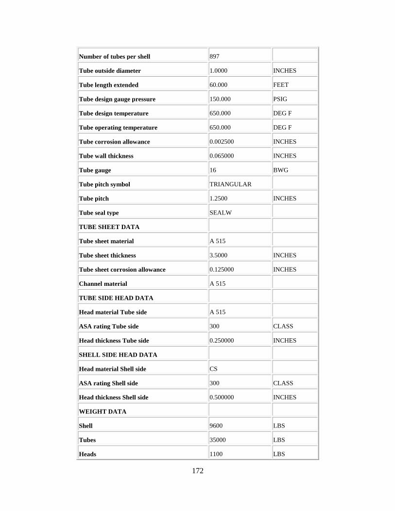
172
Number of tubes per shell 897
Tube outside diameter 1.0000 INCHES
Tube length extended 60.000 FEET
Tube design gauge pressure 150.000 PSIG
Tube design temperature 650.000 DEG F
Tube operating temperature 650.000 DEG F
Tube corrosion allowance 0.002500 INCHES
Tube wall thickness 0.065000 INCHES
Tube gauge 16 BWG
Tube pitch symbol TRIANGULAR
Tube pitch 1.2500 INCHES
Tube seal type SEALW
TUBE SHEET DATA
Tube sheet material A 515
Tube sheet thickness 3.5000 INCHES
Tube sheet corrosion allowance 0.125000 INCHES
Channel material A 515
TUBE SIDE HEAD DATA
Head material Tube side A 515
ASA rating Tube side 300 CLASS
Head thickness Tube side 0.250000 INCHES
SHELL SIDE HEAD DATA
Head material Shell side CS
ASA rating Shell side 300 CLASS
Head thickness Shell side 0.500000 INCHES
WEIGHT DATA
Shell 9600 LBS
Tubes 35000 LBS
Heads 1100 LBS

173
Internals and baffles 3700 LBS
Nozzles 1400 LBS
Flanges 3000 LBS
Base ring and lugs 80 LBS
Tube sheet 1600 LBS
Saddles 560 LBS
Fittings and miscellaneous 210 LBS
Total weight 56300 LBS
VENDOR COST DATA
Material cost 85396 DOLLARS
Shop labor cost 23843 DOLLARS
Shop overhead cost 26396 DOLLARS
Office overhead cost 12207 DOLLARS
Profit 12958 DOLLARS
Total cost 160800 DOLLARS
Cost per unit weight 2.8561 USD/LBS
Cost per unit area 11.423 USD/SF
Summary Costs
Item Material(USD) Manpower(USD) Manhours
Equipment&Setting 160800. 1803. 60
Piping 110623. 26432. 863
Civil 2495. 2709. 109
Structural Steel 0. 0. 0
Instrumentation 15964. 4065. 131
Electrical 0. 0. 0
Insulation 26907. 16337. 701
Paint 1164. 2934. 127

174
Subtotal 317953 54280 1991
Total material and manpower cost=USD 372200.
ITEM REPORT
Processing Date : Mon Apr 17 01:31:25 PM 2017
Version : Aspen Process Economic Analyzer 34.1.0(Build 3457)
List of Items :
Project : basecase
Scenario : Base Case
E-101
Project : BASECASE
Scenario : BASECASE
E-101
Item Code: DHE U TUBE
Internal Name : DHE U TUBE #10#he
Sizing Data
Design Data
Summary Costs
Sizing Data
Description Value Units
Design Data
Parameter Value Units
Item type U TUBE
Number of identical items 1
GENERAL DESIGN DATA
TEMA type BEU
Heat exchanger design option STAND

175
Heat exchanger design+cost tool ECON
Heat transfer area 7757.000 SF
Number of shells 1
Number of tube passes 2
Number of shell passes 1
Vendor grade HIGH
SHELL DATA
Shell material CS
Shell diameter 44.000 INCHES
Shell length 30.000 FEET
Shell design gauge pressure 150.000 PSIG
Shell design temperature 650.000 DEG F
Shell operating temperature 650.000 DEG F
Shell corrosion allowance 0.125000 INCHES
Shell wall thickness 0.437500 INCHES
ASA rating Shell side 300 CLASS
Number of baffles 21
Shell fabrication type PLATE
Expansion joint NO
TUBE DATA
Tube material A 214
Number of tubes per shell 494
Tube outside diameter 1.0000 INCHES
Tube length extended 60.000 FEET
Tube design gauge pressure 150.000 PSIG
Tube design temperature 650.000 DEG F
Tube operating temperature 650.000 DEG F
Tube corrosion allowance 0.002500 INCHES
Tube wall thickness 0.065000 INCHES

176
Tube gauge 16 BWG
Tube pitch symbol TRIANGULAR
Tube pitch 1.2500 INCHES
Tube seal type SEALW
TUBE SHEET DATA
Tube sheet material A 515
Tube sheet thickness 2.7500 INCHES
Tube sheet corrosion allowance 0.125000 INCHES
Channel material A 515
TUBE SIDE HEAD DATA
Head material Tube side A 515
ASA rating Tube side 300 CLASS
Head thickness Tube side 0.250000 INCHES
SHELL SIDE HEAD DATA
Head material Shell side CS
ASA rating Shell side 300 CLASS
Head thickness Shell side 0.437500 INCHES
WEIGHT DATA
Shell 6200 LBS
Tubes 19300 LBS
Heads 550 LBS
Internals and baffles 2600 LBS
Nozzles 790 LBS
Flanges 1700 LBS
Base ring and lugs 46 LBS
Tube sheet 720 LBS
Saddles 340 LBS
Fittings and miscellaneous 210 LBS
Total weight 32500 LBS

177
VENDOR COST DATA
Material cost 49133 DOLLARS
Shop labor cost 16630 DOLLARS
Shop overhead cost 17951 DOLLARS
Office overhead cost 7975 DOLLARS
Profit 8511 DOLLARS
Total cost 100200 DOLLARS
Cost per unit weight 3.0831 USD/LBS
Cost per unit area 12.917 USD/SF
Summary Costs
Item Material(USD) Manpower(USD) Manhours
Equipment&Setting 100200. 1358. 45
Piping 83602. 23015. 751
Civil 1895. 2246. 91
Structural Steel 0. 0. 0
Instrumentation 13243. 4065. 131
Electrical 0. 0. 0
Insulation 21883. 13716. 588
Paint 1047. 2643. 114
Subtotal 221870 47043 1720
Total material and manpower cost=USD 268900.
ITEM REPORT
Processing Date : Mon Apr 17 01:32:49 PM 2017
Version : Aspen Process Economic Analyzer 34.1.0(Build 3457)
List of Items :
Project : basecase
Scenario : Base Case
E-108

178
Project : BASECASE
Scenario : BASECASE
E-108
Item Code: DHE U TUBE
Internal Name : DHE U TUBE #9#he
Sizing Data
Design Data
Summary Costs
Sizing Data
Description Value Units
Design Data
Parameter Value Units
Item type U TUBE
Number of identical items 1
GENERAL DESIGN DATA
TEMA type BEU
Heat exchanger design option STAND
Heat exchanger design+cost tool ECON
Heat transfer area 6670.000 SF
Number of shells 1
Number of tube passes 2
Number of shell passes 1
Vendor grade HIGH
SHELL DATA
Shell material CS
Shell diameter 41.000 INCHES

179
Shell length 30.000 FEET
Shell design gauge pressure 150.000 PSIG
Shell design temperature 650.000 DEG F
Shell operating temperature 650.000 DEG F
Shell corrosion allowance 0.125000 INCHES
Shell wall thickness 0.437500 INCHES
ASA rating Shell side 300 CLASS
Number of baffles 22
Shell fabrication type PLATE
Expansion joint NO
TUBE DATA
Tube material A 214
Number of tubes per shell 425
Tube outside diameter 1.0000 INCHES
Tube length extended 60.000 FEET
Tube design gauge pressure 150.000 PSIG
Tube design temperature 650.000 DEG F
Tube operating temperature 650.000 DEG F
Tube corrosion allowance 0.002500 INCHES
Tube wall thickness 0.065000 INCHES
Tube gauge 16 BWG
Tube pitch symbol TRIANGULAR
Tube pitch 1.2500 INCHES
Tube seal type SEALW
TUBE SHEET DATA
Tube sheet material A 515
Tube sheet thickness 2.5000 INCHES
Tube sheet corrosion allowance 0.125000 INCHES
Channel material A 515

180
TUBE SIDE HEAD DATA
Head material Tube side A 515
ASA rating Tube side 300 CLASS
Head thickness Tube side 0.250000 INCHES
SHELL SIDE HEAD DATA
Head material Shell side CS
ASA rating Shell side 300 CLASS
Head thickness Shell side 0.437500 INCHES
WEIGHT DATA
Shell 5800 LBS
Tubes 16600 LBS
Heads 400 LBS
Internals and baffles 2400 LBS
Nozzles 790 LBS
Flanges 1500 LBS
Base ring and lugs 41 LBS
Tube sheet 580 LBS
Saddles 300 LBS
Fittings and miscellaneous 190 LBS
Total weight 28600 LBS
VENDOR COST DATA
Material cost 43011 DOLLARS
Shop labor cost 15273 DOLLARS
Shop overhead cost 16385 DOLLARS
Office overhead cost 7357 DOLLARS
Profit 7874 DOLLARS
Total cost 89900 DOLLARS
Cost per unit weight 3.1434 USD/LBS
Cost per unit area 13.478 USD/SF

181
Summary Costs
Item Material(USD) Manpower(USD) Manhours
Equipment&Setting 89900. 1358. 45
Piping 83602. 23015. 751
Civil 1784. 2156. 87
Structural Steel 0. 0. 0
Instrumentation 13243. 4065. 131
Electrical 0. 0. 0
Insulation 21592. 13461. 578
Paint 1047. 2643. 114
Subtotal 211168 46698 1706
Total material and manpower cost=USD 257900.
ITEM REPORT
Processing Date : Mon Apr 17 01:35:02 PM 2017
Version : Aspen Process Economic Analyzer 34.1.0(Build 3457)
List of Items :
Project : basecase
Scenario : Base Case
E-103
Project : BASECASE
Scenario : BASECASE
E-103
Item Code: DHE U TUBE
Internal Name : DHE U TUBE #8#he
Sizing Data
Design Data
Summary Costs

182
Sizing Data
Description Value Units
Design Data
Parameter Value Units
Item type U TUBE
Number of identical items 1
GENERAL DESIGN DATA
TEMA type BEU
Heat exchanger design option STAND
Heat exchanger design+cost tool ECON
Heat transfer area 2564.000 SF
Number of shells 1
Number of tube passes 2
Number of shell passes 1
Vendor grade HIGH
SHELL DATA
Shell material CS
Shell diameter 31.000 INCHES
Shell length 20.000 FEET
Shell design gauge pressure 150.000 PSIG
Shell design temperature 650.000 DEG F
Shell operating temperature 650.000 DEG F
Shell corrosion allowance 0.125000 INCHES
Shell wall thickness 0.437500 INCHES
ASA rating Shell side 300 CLASS
Number of baffles 16
Shell fabrication type PLATE
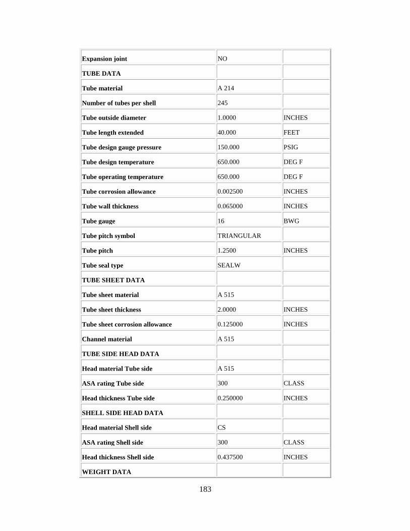
183
Expansion joint NO
TUBE DATA
Tube material A 214
Number of tubes per shell 245
Tube outside diameter 1.0000 INCHES
Tube length extended 40.000 FEET
Tube design gauge pressure 150.000 PSIG
Tube design temperature 650.000 DEG F
Tube operating temperature 650.000 DEG F
Tube corrosion allowance 0.002500 INCHES
Tube wall thickness 0.065000 INCHES
Tube gauge 16 BWG
Tube pitch symbol TRIANGULAR
Tube pitch 1.2500 INCHES
Tube seal type SEALW
TUBE SHEET DATA
Tube sheet material A 515
Tube sheet thickness 2.0000 INCHES
Tube sheet corrosion allowance 0.125000 INCHES
Channel material A 515
TUBE SIDE HEAD DATA
Head material Tube side A 515
ASA rating Tube side 300 CLASS
Head thickness Tube side 0.250000 INCHES
SHELL SIDE HEAD DATA
Head material Shell side CS
ASA rating Shell side 300 CLASS
Head thickness Shell side 0.437500 INCHES
WEIGHT DATA

184
Shell 2900 LBS
Tubes 6400 LBS
Heads 240 LBS
Internals and baffles 1100 LBS
Nozzles 390 LBS
Flanges 920 LBS
Base ring and lugs 22 LBS
Tube sheet 290 LBS
Saddles 190 LBS
Fittings and miscellaneous 110 LBS
Total weight 12600 LBS
VENDOR COST DATA
Material cost 19862 DOLLARS
Shop labor cost 9292 DOLLARS
Shop overhead cost 9948 DOLLARS
Office overhead cost 4771 DOLLARS
Profit 5227 DOLLARS
Total cost 49100 DOLLARS
Cost per unit weight 3.8968 USD/LBS
Cost per unit area 19.150 USD/SF
Summary Costs
Item Material(USD) Manpower(USD) Manhours
Equipment&Setting 49100. 1153. 38
Piping 61697. 19159. 624
Civil 1432. 1862. 75
Structural Steel 0. 0. 0
Instrumentation 13233. 3992. 128

185
Electrical 0. 0. 0
Insulation 17319. 10428. 447
Paint 905. 2304. 100
Subtotal 143686 38898 1412
Total material and manpower cost=USD 182600.
ITEM REPORT
Processing Date : Mon Apr 17 01:36:24 PM 2017
Version : Aspen Process Economic Analyzer 34.1.0(Build 3457)
List of Items :
Project : basecase
Scenario : Base Case
E-102
Project : BASECASE
Scenario : BASECASE
E-102
Item Code: DHE U TUBE
Internal Name : DHE U TUBE #7#he
Sizing Data
Design Data
Summary Costs
Sizing Data
Description Value Units
Design Data
Parameter Value Units
Item type U TUBE
Number of identical items 1
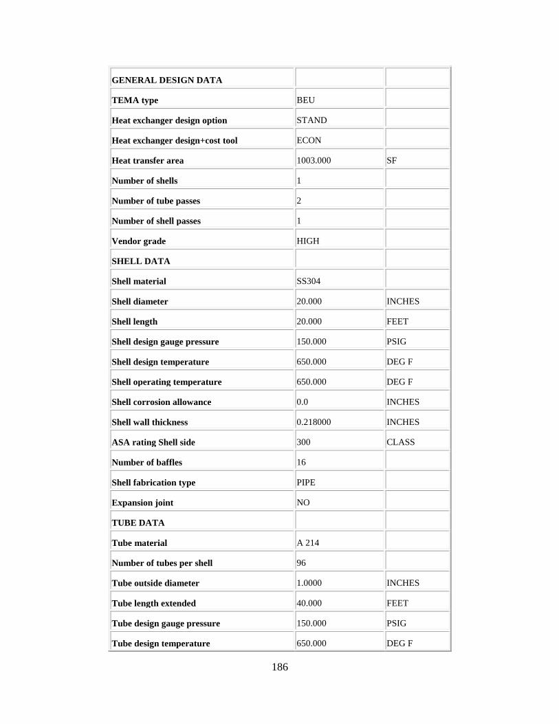
186
GENERAL DESIGN DATA
TEMA type BEU
Heat exchanger design option STAND
Heat exchanger design+cost tool ECON
Heat transfer area 1003.000 SF
Number of shells 1
Number of tube passes 2
Number of shell passes 1
Vendor grade HIGH
SHELL DATA
Shell material SS304
Shell diameter 20.000 INCHES
Shell length 20.000 FEET
Shell design gauge pressure 150.000 PSIG
Shell design temperature 650.000 DEG F
Shell operating temperature 650.000 DEG F
Shell corrosion allowance 0.0 INCHES
Shell wall thickness 0.218000 INCHES
ASA rating Shell side 300 CLASS
Number of baffles 16
Shell fabrication type PIPE
Expansion joint NO
TUBE DATA
Tube material A 214
Number of tubes per shell 96
Tube outside diameter 1.0000 INCHES
Tube length extended 40.000 FEET
Tube design gauge pressure 150.000 PSIG
Tube design temperature 650.000 DEG F

187
Tube operating temperature 650.000 DEG F
Tube corrosion allowance 0.002500 INCHES
Tube wall thickness 0.065000 INCHES
Tube gauge 16 BWG
Tube pitch symbol TRIANGULAR
Tube pitch 1.2500 INCHES
Tube seal type SEALW
TUBE SHEET DATA
Tube sheet material A 515
Tube sheet thickness 1.3750 INCHES
Tube sheet corrosion allowance 0.125000 INCHES
Channel material A 515
TUBE SIDE HEAD DATA
Head material Tube side A 515
ASA rating Tube side 300 CLASS
Head thickness Tube side 0.250000 INCHES
SHELL SIDE HEAD DATA
Head material Shell side SS304
ASA rating Shell side 300 CLASS
Head thickness Shell side 0.250000 INCHES
WEIGHT DATA
Shell 940 LBS
Tubes 2500 LBS
Heads 80 LBS
Internals and baffles 340 LBS
Nozzles 170 LBS
Flanges 410 LBS
Base ring and lugs 16 LBS
Tube sheet 100 LBS

188
Saddles 90 LBS
Fittings and miscellaneous 46 LBS
Total weight 4700 LBS
VENDOR COST DATA
Material cost 11586 DOLLARS
Shop labor cost 4610 DOLLARS
Shop overhead cost 4756 DOLLARS
Office overhead cost 3153 DOLLARS
Profit 3495 DOLLARS
Total cost 27600 DOLLARS
Cost per unit weight 5.8723 USD/LBS
Cost per unit area 27.517 USD/SF
Summary Costs
Item Material(USD) Manpower(USD) Manhours
Equipment&Setting 27600. 1153. 38
Piping 65279. 18964. 618
Civil 1225. 1708. 69
Structural Steel 0. 0. 0
Instrumentation 11506. 3992. 128
Electrical 0. 0. 0
Insulation 14562. 8526. 366
Paint 438. 1106. 48
Subtotal 120610 35449 1267
Total material and manpower cost=USD 156100.
ITEM REPORT
Processing Date : Mon Apr 17 01:37:12 PM 2017
Version : Aspen Process Economic Analyzer 34.1.0(Build 3457)

189
List of Items :
Project : basecase
Scenario : Base Case
E-105
Project : BASECASE
Scenario : BASECASE
E-105
Item Code: DHE U TUBE
Internal Name : DHE U TUBE #6#he
Sizing Data
Design Data
Summary Costs
Sizing Data
Description Value Units
Design Data
Parameter Value Units
Item type U TUBE
Number of identical items 1
GENERAL DESIGN DATA
TEMA type BEU
Heat exchanger design option STAND
Heat exchanger design+cost tool ECON
Heat transfer area 516.000 SF
Number of shells 1
Number of tube passes 2
Number of shell passes 1

190
Vendor grade HIGH
SHELL DATA
Shell material CS
Shell diameter 16.000 INCHES
Shell length 16.000 FEET
Shell design gauge pressure 150.000 PSIG
Shell design temperature 650.000 DEG F
Shell operating temperature 650.000 DEG F
Shell corrosion allowance 0.125000 INCHES
Shell wall thickness 0.375000 INCHES
ASA rating Shell side 300 CLASS
Number of baffles 13
Shell fabrication type PIPE
Expansion joint NO
TUBE DATA
Tube material A 214
Number of tubes per shell 62
Tube outside diameter 1.0000 INCHES
Tube length extended 32.000 FEET
Tube design gauge pressure 150.000 PSIG
Tube design temperature 650.000 DEG F
Tube operating temperature 650.000 DEG F
Tube corrosion allowance 0.002500 INCHES
Tube wall thickness 0.065000 INCHES
Tube gauge 16 BWG
Tube pitch symbol TRIANGULAR
Tube pitch 1.2500 INCHES
Tube seal type SEALW
TUBE SHEET DATA
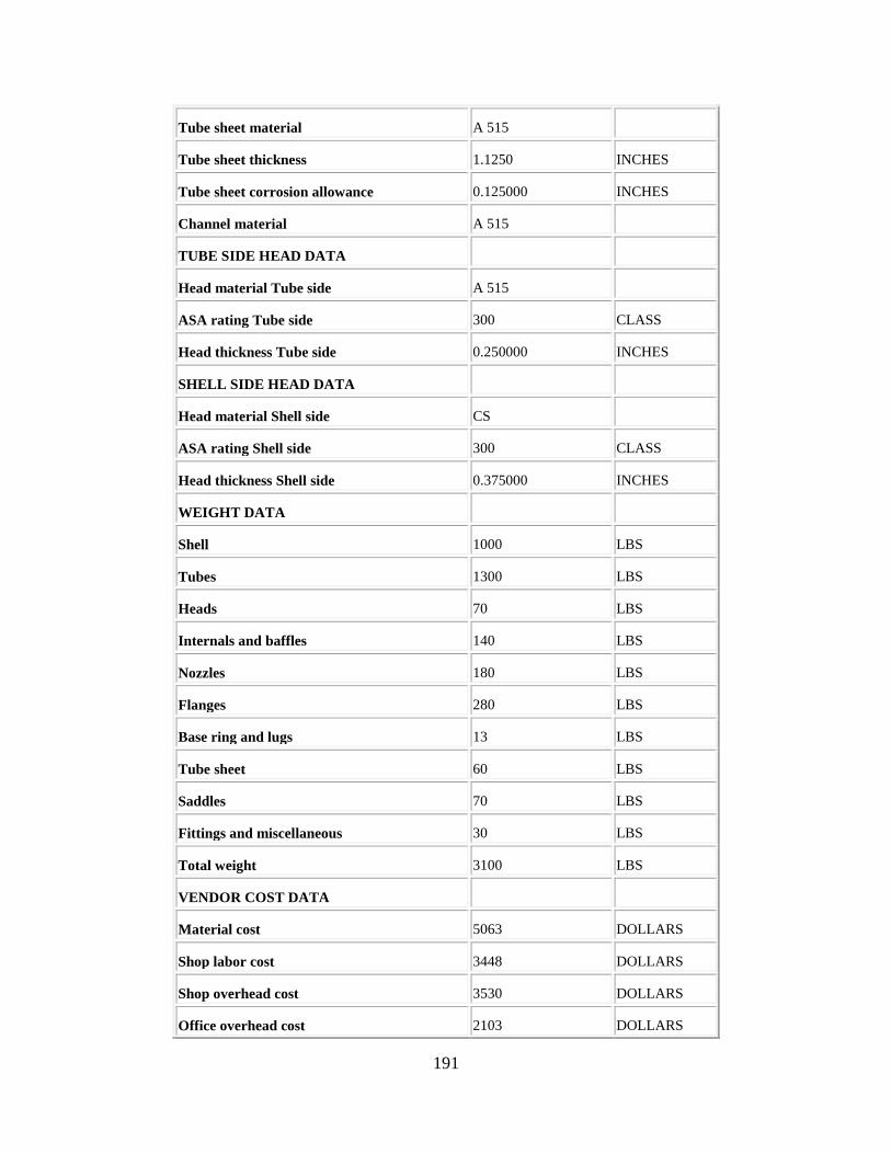
191
Tube sheet material A 515
Tube sheet thickness 1.1250 INCHES
Tube sheet corrosion allowance 0.125000 INCHES
Channel material A 515
TUBE SIDE HEAD DATA
Head material Tube side A 515
ASA rating Tube side 300 CLASS
Head thickness Tube side 0.250000 INCHES
SHELL SIDE HEAD DATA
Head material Shell side CS
ASA rating Shell side 300 CLASS
Head thickness Shell side 0.375000 INCHES
WEIGHT DATA
Shell 1000 LBS
Tubes 1300 LBS
Heads 70 LBS
Internals and baffles 140 LBS
Nozzles 180 LBS
Flanges 280 LBS
Base ring and lugs 13 LBS
Tube sheet 60 LBS
Saddles 70 LBS
Fittings and miscellaneous 30 LBS
Total weight 3100 LBS
VENDOR COST DATA
Material cost 5063 DOLLARS
Shop labor cost 3448 DOLLARS
Shop overhead cost 3530 DOLLARS
Office overhead cost 2103 DOLLARS

192
Profit 2356 DOLLARS
Total cost 16500 DOLLARS
Cost per unit weight 5.3226 USD/LBS
Cost per unit area 31.977 USD/SF
Summary Costs
Item Material(USD) Manpower(USD) Manhours
Equipment&Setting 16500. 1054. 35
Piping 30881. 14093. 458
Civil 1131. 1620. 66
Structural Steel 0. 0. 0
Instrumentation 11566. 3960. 127
Electrical 0. 0. 0
Insulation 11434. 7213. 309
Paint 622. 1603. 69
Subtotal 72134 29543 1064
Total material and manpower cost=USD 101700.
ITEM REPORT
Processing Date : Mon Apr 17 01:37:55 PM 2017
Version : Aspen Process Economic Analyzer 34.1.0(Build 3457)
List of Items :
Project : basecase
Scenario : Base Case
E-104
Project : BASECASE
Scenario : BASECASE

193
E-104
Item Code: DHE U TUBE
Internal Name : DHE U TUBE #5#he
Sizing Data
Design Data
Summary Costs
Sizing Data
Description Value Units
Design Data
Parameter Value Units
Item type U TUBE
Number of identical items 1
GENERAL DESIGN DATA
TEMA type BEU
Heat exchanger design option STAND
Heat exchanger design+cost tool ECON
Heat transfer area 4700.000 SF
Number of shells 1
Number of tube passes 2
Number of shell passes 1
Vendor grade HIGH
SHELL DATA
Shell material CS
Shell diameter 42.000 INCHES
Shell length 20.000 FEET
Shell design gauge pressure 150.000 PSIG
Shell design temperature 650.000 DEG F
Shell operating temperature 650.000 DEG F
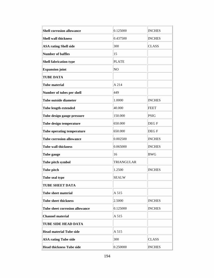
194
Shell corrosion allowance 0.125000 INCHES
Shell wall thickness 0.437500 INCHES
ASA rating Shell side 300 CLASS
Number of baffles 15
Shell fabrication type PLATE
Expansion joint NO
TUBE DATA
Tube material A 214
Number of tubes per shell 449
Tube outside diameter 1.0000 INCHES
Tube length extended 40.000 FEET
Tube design gauge pressure 150.000 PSIG
Tube design temperature 650.000 DEG F
Tube operating temperature 650.000 DEG F
Tube corrosion allowance 0.002500 INCHES
Tube wall thickness 0.065000 INCHES
Tube gauge 16 BWG
Tube pitch symbol TRIANGULAR
Tube pitch 1.2500 INCHES
Tube seal type SEALW
TUBE SHEET DATA
Tube sheet material A 515
Tube sheet thickness 2.5000 INCHES
Tube sheet corrosion allowance 0.125000 INCHES
Channel material A 515
TUBE SIDE HEAD DATA
Head material Tube side A 515
ASA rating Tube side 300 CLASS
Head thickness Tube side 0.250000 INCHES

195
SHELL SIDE HEAD DATA
Head material Shell side CS
ASA rating Shell side 300 CLASS
Head thickness Shell side 0.437500 INCHES
WEIGHT DATA
Shell 4000 LBS
Tubes 11700 LBS
Heads 420 LBS
Internals and baffles 1800 LBS
Nozzles 790 LBS
Flanges 1600 LBS
Base ring and lugs 32 LBS
Tube sheet 610 LBS
Saddles 310 LBS
Fittings and miscellaneous 130 LBS
Total weight 21400 LBS
VENDOR COST DATA
Material cost 34355 DOLLARS
Shop labor cost 13147 DOLLARS
Shop overhead cost 14240 DOLLARS
Office overhead cost 6579 DOLLARS
Profit 7079 DOLLARS
Total cost 75400 DOLLARS
Cost per unit weight 3.5234 USD/LBS
Cost per unit area 16.043 USD/SF
Summary Costs
Item Material(USD) Manpower(USD) Manhours

196
Equipment&Setting 75400. 1153. 38
Piping 61697. 19159. 624
Civil 1821. 2186. 88
Structural Steel 0. 0. 0
Instrumentation 13233. 3992. 128
Electrical 0. 0. 0
Insulation 18087. 11210. 481
Paint 905. 2304. 100
Subtotal 171143 40004 1459
Total material and manpower cost=USD 211100.
ITEM REPORT
Processing Date : Mon Apr 17 01:38:21 PM 2017
Version : Aspen Process Economic Analyzer 34.1.0(Build 3457)
List of Items :
Project : basecase
Scenario : Base Case
E-109
Project : BASECASE
Scenario : BASECASE
E-109
Item Code: DHE U TUBE
Internal Name : DHE U TUBE #4#he
Sizing Data
Design Data
Summary Costs
Sizing Data
Description Value Units

197
Design Data
Parameter Value Units
Item type U TUBE
Number of identical items 1
GENERAL DESIGN DATA
TEMA type BEU
Heat exchanger design option STAND
Heat exchanger design+cost tool ECON
Heat transfer area 1181.000 SF
Number of shells 1
Number of tube passes 2
Number of shell passes 1
Vendor grade HIGH
SHELL DATA
Shell material CS
Shell diameter 21.000 INCHES
Shell length 20.000 FEET
Shell design gauge pressure 150.000 PSIG
Shell design temperature 650.000 DEG F
Shell operating temperature 650.000 DEG F
Shell corrosion allowance 0.125000 INCHES
Shell wall thickness 0.375000 INCHES
ASA rating Shell side 300 CLASS
Number of baffles 16
Shell fabrication type PIPE
Expansion joint NO
TUBE DATA
Tube material A 214

198
Number of tubes per shell 113
Tube outside diameter 1.0000 INCHES
Tube length extended 40.000 FEET
Tube design gauge pressure 150.000 PSIG
Tube design temperature 650.000 DEG F
Tube operating temperature 650.000 DEG F
Tube corrosion allowance 0.002500 INCHES
Tube wall thickness 0.065000 INCHES
Tube gauge 16 BWG
Tube pitch symbol TRIANGULAR
Tube pitch 1.2500 INCHES
Tube seal type SEALW
TUBE SHEET DATA
Tube sheet material A 515
Tube sheet thickness 1.3750 INCHES
Tube sheet corrosion allowance 0.125000 INCHES
Channel material A 515
TUBE SIDE HEAD DATA
Head material Tube side A 515
ASA rating Tube side 300 CLASS
Head thickness Tube side 0.250000 INCHES
SHELL SIDE HEAD DATA
Head material Shell side CS
ASA rating Shell side 300 CLASS
Head thickness Shell side 0.375000 INCHES
WEIGHT DATA
Shell 1700 LBS
Tubes 2900 LBS
Heads 110 LBS

199
Internals and baffles 360 LBS
Nozzles 250 LBS
Flanges 450 LBS
Base ring and lugs 16 LBS
Tube sheet 100 LBS
Saddles 100 LBS
Fittings and miscellaneous 45 LBS
Total weight 6000 LBS
VENDOR COST DATA
Material cost 9812 DOLLARS
Shop labor cost 4501 DOLLARS
Shop overhead cost 4669 DOLLARS
Office overhead cost 2754 DOLLARS
Profit 3064 DOLLARS
Total cost 24800 DOLLARS
Cost per unit weight 4.1333 USD/LBS
Cost per unit area 20.999 USD/SF
Summary Costs
Item Material(USD) Manpower(USD) Manhours
Equipment&Setting 24800. 1153. 38
Piping 45190. 16488. 537
Civil 1272. 1751. 71
Structural Steel 0. 0. 0
Instrumentation 11087. 3992. 128
Electrical 0. 0. 0
Insulation 14639. 8619. 370
Paint 769. 1965. 85
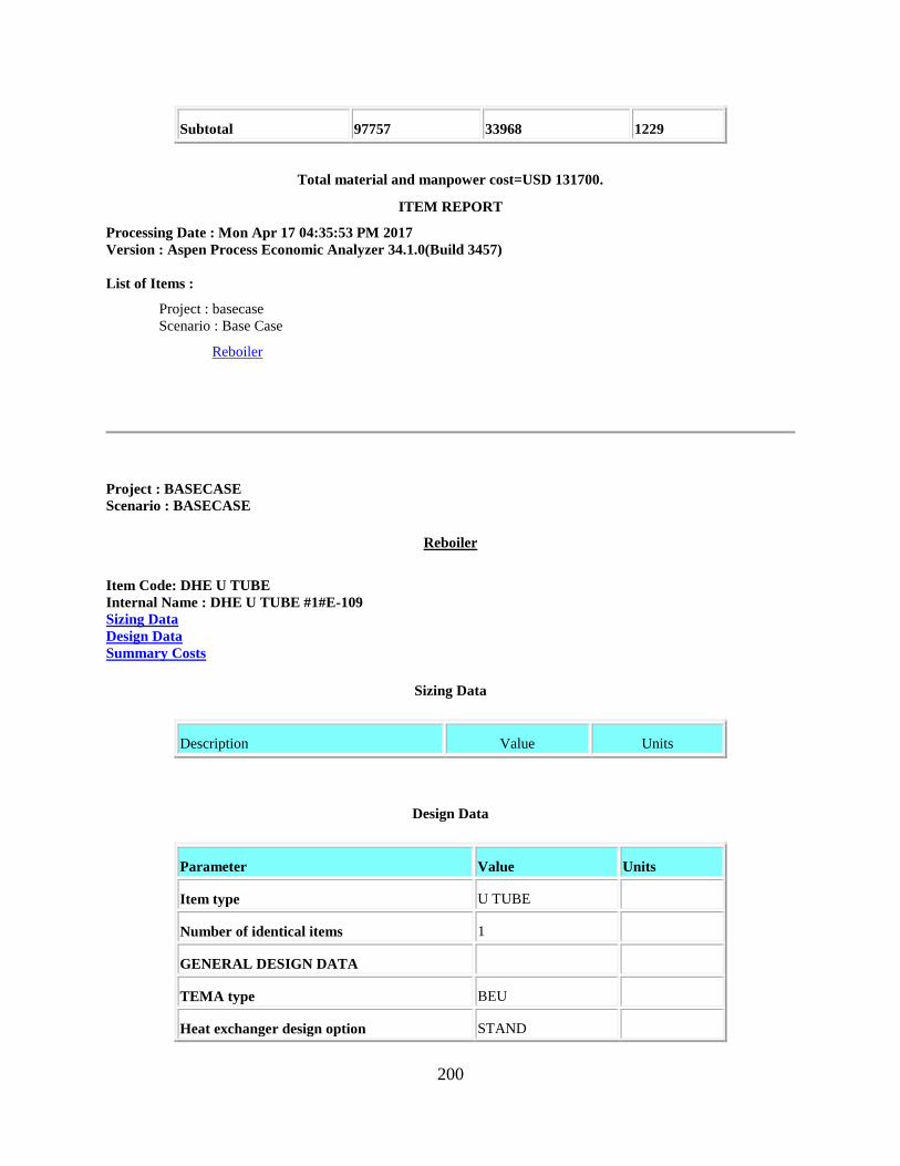
200
Subtotal 97757 33968 1229
Total material and manpower cost=USD 131700.
ITEM REPORT
Processing Date : Mon Apr 17 04:35:53 PM 2017
Version : Aspen Process Economic Analyzer 34.1.0(Build 3457)
List of Items :
Project : basecase
Scenario : Base Case
Reboiler
Project : BASECASE
Scenario : BASECASE
Reboiler
Item Code: DHE U TUBE
Internal Name : DHE U TUBE #1#E-109
Sizing Data
Design Data
Summary Costs
Sizing Data
Description Value Units
Design Data
Parameter Value Units
Item type U TUBE
Number of identical items 1
GENERAL DESIGN DATA
TEMA type BEU
Heat exchanger design option STAND

201
Heat exchanger design+cost tool ECON
Heat transfer area 5272.000 SF
Number of shells 1
Number of tube passes 2
Number of shell passes 1
Vendor grade HIGH
SHELL DATA
Shell material CS
Shell diameter 44.000 INCHES
Shell length 20.000 FEET
Shell design gauge pressure 150.000 PSIG
Shell design temperature 650.000 DEG F
Shell operating temperature 650.000 DEG F
Shell corrosion allowance 0.125000 INCHES
Shell wall thickness 0.437500 INCHES
ASA rating Shell side 300 CLASS
Number of baffles 15
Shell fabrication type PLATE
Expansion joint NO
TUBE DATA
Tube material A 214
Number of tubes per shell 504
Tube outside diameter 1.0000 INCHES
Tube length extended 40.000 FEET
Tube design gauge pressure 150.000 PSIG
Tube design temperature 650.000 DEG F
Tube operating temperature 650.000 DEG F
Tube corrosion allowance 0.002500 INCHES
Tube wall thickness 0.065000 INCHES

202
Tube gauge 16 BWG
Tube pitch symbol TRIANGULAR
Tube pitch 1.2500 INCHES
Tube seal type SEALW
TUBE SHEET DATA
Tube sheet material A 515
Tube sheet thickness 2.7500 INCHES
Tube sheet corrosion allowance 0.125000 INCHES
Channel material A 515
TUBE SIDE HEAD DATA
Head material Tube side A 515
ASA rating Tube side 300 CLASS
Head thickness Tube side 0.250000 INCHES
SHELL SIDE HEAD DATA
Head material Shell side CS
ASA rating Shell side 300 CLASS
Head thickness Shell side 0.437500 INCHES
WEIGHT DATA
Shell 4200 LBS
Tubes 13100 LBS
Heads 550 LBS
Internals and baffles 2000 LBS
Nozzles 790 LBS
Flanges 1700 LBS
Base ring and lugs 34 LBS
Tube sheet 710 LBS
Saddles 340 LBS
Fittings and miscellaneous 140 LBS
Total weight 23600 LBS

203
VENDOR COST DATA
Material cost 38032 DOLLARS
Shop labor cost 14212 DOLLARS
Shop overhead cost 15499 DOLLARS
Office overhead cost 7035 DOLLARS
Profit 7522 DOLLARS
Total cost 82300 DOLLARS
Cost per unit weight 3.4873 USD/LBS
Cost per unit area 15.611 USD/SF
Summary Costs
Item Material(USD) Manpower(USD) Manhours
Equipment&Setting 82300. 1153. 38
Piping 61697. 19159. 624
Civil 1895. 2246. 91
Structural Steel 0. 0. 0
Instrumentation 13233. 3992. 128
Electrical 0. 0. 0
Insulation 18233. 11350. 487
Paint 905. 2304. 100
Subtotal 178263 40204 1468
Total material and manpower cost=USD 218500.
ITEM REPORT
Processing Date : Mon Apr 17 04:38:16 PM 2017
Version : Aspen Process Economic Analyzer 34.1.0(Build 3457)
List of Items :
Project : basecase
Scenario : Base Case
Condenser

204
Project : BASECASE
Scenario : BASECASE
Condenser
Item Code: DHE U TUBE
Internal Name : DHE U TUBE #2#E-109
Sizing Data
Design Data
Summary Costs
Sizing Data
Description Value Units
Design Data
Parameter Value Units
Item type U TUBE
Number of identical items 1
GENERAL DESIGN DATA
TEMA type BEU
Heat exchanger design option STAND
Heat exchanger design+cost tool ECON
Heat transfer area 5880.000 SF
Number of shells 1
Number of tube passes 2
Number of shell passes 1
Vendor grade HIGH
SHELL DATA
Shell material CS
Shell diameter 47.000 INCHES

205
Shell length 20.000 FEET
Shell design gauge pressure 150.000 PSIG
Shell design temperature 650.000 DEG F
Shell operating temperature 650.000 DEG F
Shell corrosion allowance 0.125000 INCHES
Shell wall thickness 0.437500 INCHES
ASA rating Shell side 300 CLASS
Number of baffles 14
Shell fabrication type PLATE
Expansion joint NO
TUBE DATA
Tube material A 214
Number of tubes per shell 562
Tube outside diameter 1.0000 INCHES
Tube length extended 40.000 FEET
Tube design gauge pressure 150.000 PSIG
Tube design temperature 650.000 DEG F
Tube operating temperature 650.000 DEG F
Tube corrosion allowance 0.002500 INCHES
Tube wall thickness 0.065000 INCHES
Tube gauge 16 BWG
Tube pitch symbol TRIANGULAR
Tube pitch 1.2500 INCHES
Tube seal type SEALW
TUBE SHEET DATA
Tube sheet material A 515
Tube sheet thickness 3.0000 INCHES
Tube sheet corrosion allowance 0.125000 INCHES
Channel material A 515

206
TUBE SIDE HEAD DATA
Head material Tube side A 515
ASA rating Tube side 300 CLASS
Head thickness Tube side 0.250000 INCHES
SHELL SIDE HEAD DATA
Head material Shell side CS
ASA rating Shell side 300 CLASS
Head thickness Shell side 0.437500 INCHES
WEIGHT DATA
Shell 4400 LBS
Tubes 14600 LBS
Heads 630 LBS
Internals and baffles 2100 LBS
Nozzles 880 LBS
Flanges 2000 LBS
Base ring and lugs 38 LBS
Tube sheet 890 LBS
Saddles 380 LBS
Fittings and miscellaneous 140 LBS
Total weight 26100 LBS
VENDOR COST DATA
Material cost 42280 DOLLARS
Shop labor cost 15355 DOLLARS
Shop overhead cost 16859 DOLLARS
Office overhead cost 7550 DOLLARS
Profit 8056 DOLLARS
Total cost 90100 DOLLARS
Cost per unit weight 3.4521 USD/LBS
Cost per unit area 15.323 USD/SF
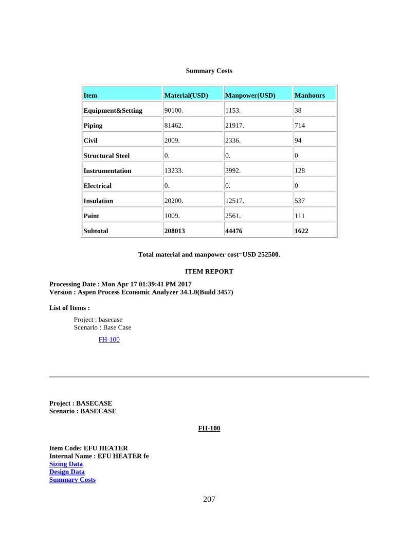
207
Summary Costs
Item Material(USD) Manpower(USD) Manhours
Equipment&Setting 90100. 1153. 38
Piping 81462. 21917. 714
Civil 2009. 2336. 94
Structural Steel 0. 0. 0
Instrumentation 13233. 3992. 128
Electrical 0. 0. 0
Insulation 20200. 12517. 537
Paint 1009. 2561. 111
Subtotal 208013 44476 1622
Total material and manpower cost=USD 252500.
ITEM REPORT
Processing Date : Mon Apr 17 01:39:41 PM 2017
Version : Aspen Process Economic Analyzer 34.1.0(Build 3457)
List of Items :
Project : basecase
Scenario : Base Case
FH-100
Project : BASECASE
Scenario : BASECASE
FH-100
Item Code: EFU HEATER
Internal Name : EFU HEATER fe
Sizing Data
Design Data
Summary Costs

208
Sizing Data
Description Value Units
Design Data
Parameter Value Units
Item type HEATER
Material 304LW
Duty 183.000 MMBTU/H
Design gauge pressure 45.000 PSIG
Design temperature 1100.000 DEG F
Standard gas flow rate 26213.00 CFM
Source of quote SG
Process type GAS
Total weight 756100 LBS
Summary Costs
Item Material(USD) Manpower(USD) Manhours
Equipment&Setting 3038600. 89356. 3100
Piping 187676. 45683. 1490
Civil 40994. 24658. 996
Structural Steel 0. 0. 0
Instrumentation 219180. 12384. 396
Electrical 30606. 9105. 301
Insulation 34151. 46738. 2009
Paint 1130. 2348. 103
Subtotal 3552337 230272 8395

209
Total material and manpower cost=USD 3782600.
ITEM REPORT
Processing Date : Mon Apr 17 01:43:45 PM 2017
Version : Aspen Process Economic Analyzer 34.1.0(Build 3457)
List of Items :
Project : basecase
Scenario : Base Case
MRU
Project : BASECASE
Scenario : BASECASE
MRU
Item Code: DVT CYLINDER
Internal Name : DVT CYLINDER MRU
Sizing Data
Design Data
Summary Costs
Sizing Data
Description Value Units
Design Data
Parameter Value Units
Item type CYLINDER
Number of identical items 1
EQUIPMENT DESIGN DATA
ASME design basis D1NF
Liquid volume 1100.000 GALLONS
Design gauge pressure 425.000 PSIG

210
Design temperature 200.000 DEG F
Operating temperature 200.000 DEG F
Fluid specific gravity 1.0000
SHELL DATA
Shell material SS304
Diameter option ID
Vessel diameter 4.0000 FEET
Vessel tangent to tangent height 11.000 FEET
Head type ELLIP
MECHANICAL DESIGN DATA
Wind or seismic design W+S
Weld efficiency 85.000 PERCENT
Base material thickness 0.750000 INCHES
Corrosion allowance 0.0 INCHES
Head thickness Top 0.625000 INCHES
Head thickness Bottom 0.625000 INCHES
THICKNESSES REQUIRED
Circumferential stress thickness 0.733797 INCHES
VESSEL LEG DATA
Leg material CS
Vessel leg height 4.0000 FEET
NOZZLE AND MANHOLE DATA
Nozzle ASA rating 300 CLASS
Nozzle material SS304
Nozzle A Quantity 1
Nozzle A Diameter 4.0000 IN DIAM
Nozzle A Location S
Nozzle B Quantity 1
Nozzle B Diameter 6.0000 IN DIAM
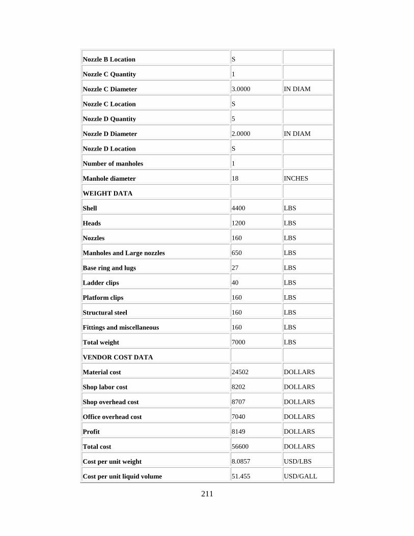
211
Nozzle B Location S
Nozzle C Quantity 1
Nozzle C Diameter 3.0000 IN DIAM
Nozzle C Location S
Nozzle D Quantity 5
Nozzle D Diameter 2.0000 IN DIAM
Nozzle D Location S
Number of manholes 1
Manhole diameter 18 INCHES
WEIGHT DATA
Shell 4400 LBS
Heads 1200 LBS
Nozzles 160 LBS
Manholes and Large nozzles 650 LBS
Base ring and lugs 27 LBS
Ladder clips 40 LBS
Platform clips 160 LBS
Structural steel 160 LBS
Fittings and miscellaneous 160 LBS
Total weight 7000 LBS
VENDOR COST DATA
Material cost 24502 DOLLARS
Shop labor cost 8202 DOLLARS
Shop overhead cost 8707 DOLLARS
Office overhead cost 7040 DOLLARS
Profit 8149 DOLLARS
Total cost 56600 DOLLARS
Cost per unit weight 8.0857 USD/LBS
Cost per unit liquid volume 51.455 USD/GALL

212
Summary Costs
Item Material(USD) Manpower(USD) Manhours
Equipment&Setting 56600. 790. 25
Piping 41596. 17000. 552
Civil 1990. 2104. 86
Structural Steel 7690. 1278. 44
Instrumentation 34079. 5279. 169
Electrical 1038. 687. 23
Insulation 4796. 4791. 206
Paint 146. 221. 10
Subtotal 147935 32150 1115
Total material and manpower cost=USD 180100.
ITEM REPORT
Processing Date : Mon Apr 17 01:44:51 PM 2017
Version : Aspen Process Economic Analyzer 34.1.0(Build 3457)
List of Items :
Project : basecase
Scenario : Base Case
ATU
Project : BASECASE
Scenario : BASECASE
ATU
Item Code: DVT CYLINDER
Internal Name : DVT CYLINDER #3#MRU
Sizing Data
Design Data
Summary Costs

213
Sizing Data
Description Value Units
Design Data
Parameter Value Units
Item type CYLINDER
Number of identical items 1
EQUIPMENT DESIGN DATA
ASME design basis D1NF
Liquid volume 190.000 GALLONS
Design gauge pressure 425.000 PSIG
Design temperature 650.000 DEG F
Operating temperature 650.000 DEG F
Fluid specific gravity 1.0000
SHELL DATA
Shell material CS
Diameter option ID
Vessel diameter 2.0000 FEET
Vessel tangent to tangent height 8.0000 FEET
Head type ELLIP
MECHANICAL DESIGN DATA
Wind or seismic design W+S
Weld efficiency 85.000 PERCENT
Base material thickness 0.437500 INCHES
Corrosion allowance 0.0 INCHES
Head thickness Top 0.375000 INCHES
Head thickness Bottom 0.375000 INCHES
THICKNESSES REQUIRED
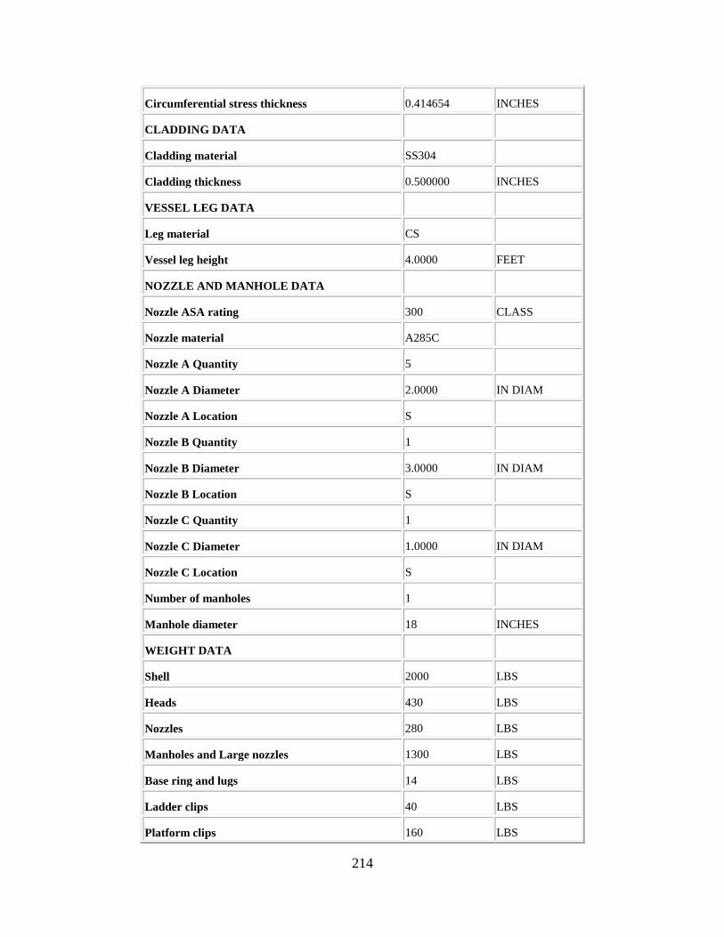
214
Circumferential stress thickness 0.414654 INCHES
CLADDING DATA
Cladding material SS304
Cladding thickness 0.500000 INCHES
VESSEL LEG DATA
Leg material CS
Vessel leg height 4.0000 FEET
NOZZLE AND MANHOLE DATA
Nozzle ASA rating 300 CLASS
Nozzle material A285C
Nozzle A Quantity 5
Nozzle A Diameter 2.0000 IN DIAM
Nozzle A Location S
Nozzle B Quantity 1
Nozzle B Diameter 3.0000 IN DIAM
Nozzle B Location S
Nozzle C Quantity 1
Nozzle C Diameter 1.0000 IN DIAM
Nozzle C Location S
Number of manholes 1
Manhole diameter 18 INCHES
WEIGHT DATA
Shell 2000 LBS
Heads 430 LBS
Nozzles 280 LBS
Manholes and Large nozzles 1300 LBS
Base ring and lugs 14 LBS
Ladder clips 40 LBS
Platform clips 160 LBS
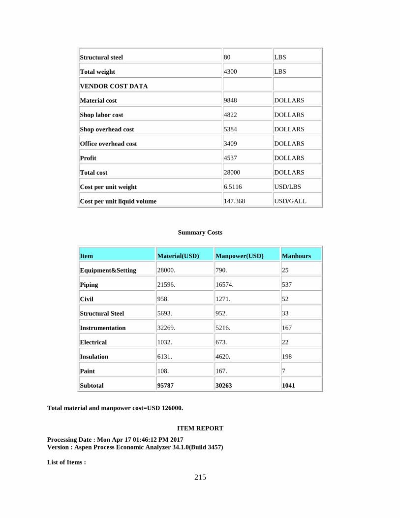
215
Structural steel 80 LBS
Total weight 4300 LBS
VENDOR COST DATA
Material cost 9848 DOLLARS
Shop labor cost 4822 DOLLARS
Shop overhead cost 5384 DOLLARS
Office overhead cost 3409 DOLLARS
Profit 4537 DOLLARS
Total cost 28000 DOLLARS
Cost per unit weight 6.5116 USD/LBS
Cost per unit liquid volume 147.368 USD/GALL
Summary Costs
Item Material(USD) Manpower(USD) Manhours
Equipment&Setting 28000. 790. 25
Piping 21596. 16574. 537
Civil 958. 1271. 52
Structural Steel 5693. 952. 33
Instrumentation 32269. 5216. 167
Electrical 1032. 673. 22
Insulation 6131. 4620. 198
Paint 108. 167. 7
Subtotal 95787 30263 1041
Total material and manpower cost=USD 126000.
ITEM REPORT
Processing Date : Mon Apr 17 01:46:12 PM 2017
Version : Aspen Process Economic Analyzer 34.1.0(Build 3457)
List of Items :
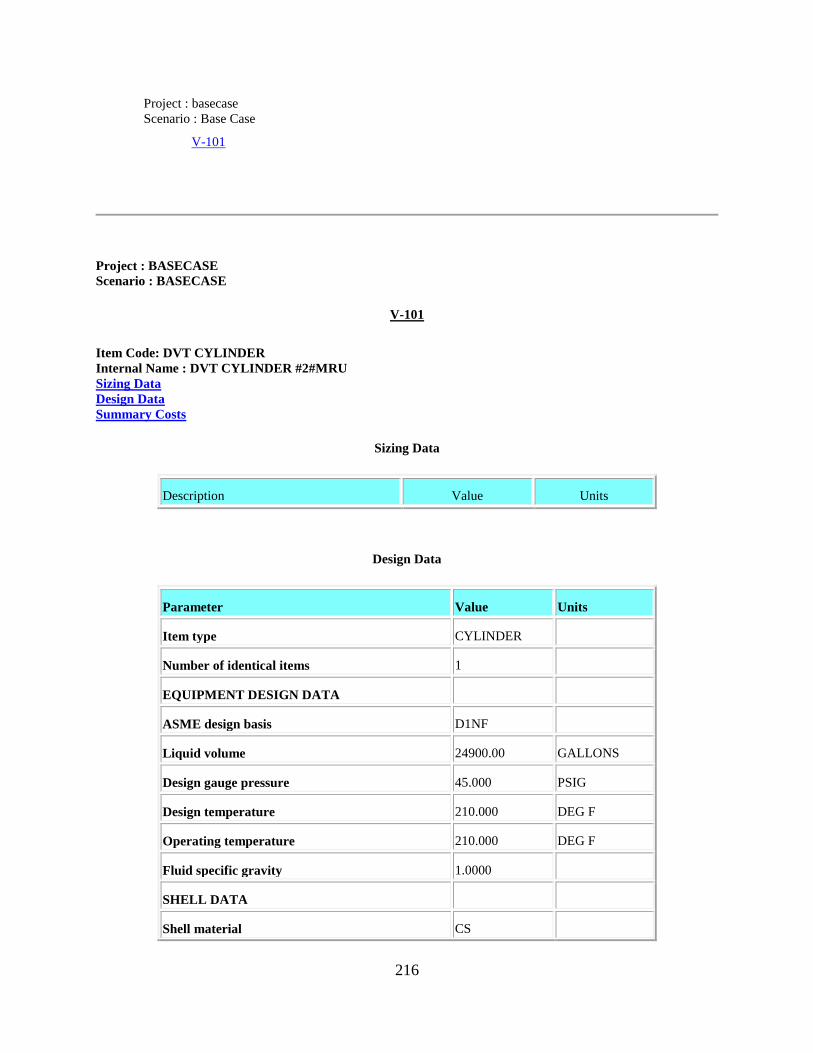
216
Project : basecase
Scenario : Base Case
V-101
Project : BASECASE
Scenario : BASECASE
V-101
Item Code: DVT CYLINDER
Internal Name : DVT CYLINDER #2#MRU
Sizing Data
Design Data
Summary Costs
Sizing Data
Description Value Units
Design Data
Parameter Value Units
Item type CYLINDER
Number of identical items 1
EQUIPMENT DESIGN DATA
ASME design basis D1NF
Liquid volume 24900.00 GALLONS
Design gauge pressure 45.000 PSIG
Design temperature 210.000 DEG F
Operating temperature 210.000 DEG F
Fluid specific gravity 1.0000
SHELL DATA
Shell material CS

217
Diameter option ID
Vessel diameter 11.000 FEET
Vessel tangent to tangent height 35.000 FEET
Head type HEMI
MECHANICAL DESIGN DATA
Wind or seismic design W+S
Fluid volume 20.000 PERCENT
Weld efficiency 85.000 PERCENT
Base material thickness 0.375000 INCHES
Corrosion allowance 0.125000 INCHES
Head thickness Top 0.312500 INCHES
Head thickness Bottom 0.312500 INCHES
THICKNESSES REQUIRED
Circumferential stress thickness 0.241838 INCHES
Long tensile stress thickness 0.106090 INCHES
Long compressive stress thick 0.134499 INCHES
VESSEL SKIRT DATA
Skirt material CS
Skirt height 17.000 FEET
Skirt thickness 0.312500 INCHES
NOZZLE AND MANHOLE DATA
Nozzle ASA rating 150 CLASS
Nozzle material A285C
Nozzle A Quantity 1
Nozzle A Diameter 12.000 IN DIAM
Nozzle A Location S
Nozzle B Quantity 1
Nozzle B Diameter 14.000 IN DIAM
Nozzle B Location S

218
Nozzle C Quantity 1
Nozzle C Diameter 10.000 IN DIAM
Nozzle C Location S
Nozzle D Quantity 1
Nozzle D Diameter 8.0000 IN DIAM
Nozzle D Location S
Nozzle E Quantity 6
Nozzle E Diameter 2.0000 IN DIAM
Nozzle E Location S
Number of manholes 1
Manhole diameter 18 INCHES
WEIGHT DATA
Shell 18600 LBS
Heads 4900 LBS
Nozzles 580 LBS
Manholes and Large nozzles 410 LBS
Skirt 7500 LBS
Base ring and lugs 1800 LBS
Ladder clips 150 LBS
Platform clips 490 LBS
Fittings and miscellaneous 160 LBS
Total weight 34600 LBS
VENDOR COST DATA
Material cost 30244 DOLLARS
Shop labor cost 22808 DOLLARS
Shop overhead cost 24094 DOLLARS
Office overhead cost 13115 DOLLARS
Profit 12639 DOLLARS
Total cost 102900 DOLLARS

219
Cost per unit weight 2.9740 USD/LBS
Cost per unit liquid volume 4.1325 USD/GALL
Summary Costs
Item Material(USD) Manpower(USD) Manhours
Equipment&Setting 102900. 3267. 103
Piping 63770. 22903. 747
Civil 7494. 6779. 272
Structural Steel 22663. 3816. 132
Instrumentation 64244. 5530. 177
Electrical 2708. 1458. 49
Insulation 17402. 15550. 668
Paint 1532. 3431. 149
Subtotal 282713 62734 2297
Total material and manpower cost=USD 345400.
ITEM REPORT
Processing Date : Mon Apr 17 01:47:10 PM 2017
Version : Aspen Process Economic Analyzer 34.1.0(Build 3457)
List of Items :
Project : basecase
Scenario : Base Case
V-100
Project : BASECASE
Scenario : BASECASE
V-100
Item Code: DVT CYLINDER
Internal Name : DVT CYLINDER #1#MRU

220
Sizing Data
Design Data
Summary Costs
Sizing Data
Description Value Units
Design Data
Parameter Value Units
Item type CYLINDER
Number of identical items 1
EQUIPMENT DESIGN DATA
ASME design basis D1NF
Liquid volume 8700.000 GALLONS
Design gauge pressure 45.000 PSIG
Design temperature 80.000 DEG F
Operating temperature 80.000 DEG F
Fluid specific gravity 1.0000
SHELL DATA
Shell material CS
Diameter option ID
Vessel diameter 7.0000 FEET
Vessel tangent to tangent height 30.000 FEET
Head type ELLIP
MECHANICAL DESIGN DATA
Wind or seismic design W+S
Fluid volume 20.000 PERCENT
Weld efficiency 85.000 PERCENT
Base material thickness 0.312500 INCHES
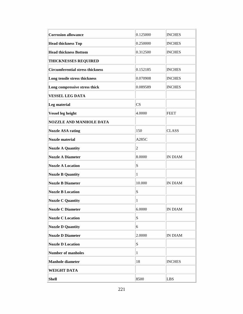
221
Corrosion allowance 0.125000 INCHES
Head thickness Top 0.250000 INCHES
Head thickness Bottom 0.312500 INCHES
THICKNESSES REQUIRED
Circumferential stress thickness 0.152185 INCHES
Long tensile stress thickness 0.070908 INCHES
Long compressive stress thick 0.089589 INCHES
VESSEL LEG DATA
Leg material CS
Vessel leg height 4.0000 FEET
NOZZLE AND MANHOLE DATA
Nozzle ASA rating 150 CLASS
Nozzle material A285C
Nozzle A Quantity 2
Nozzle A Diameter 8.0000 IN DIAM
Nozzle A Location S
Nozzle B Quantity 1
Nozzle B Diameter 10.000 IN DIAM
Nozzle B Location S
Nozzle C Quantity 1
Nozzle C Diameter 6.0000 IN DIAM
Nozzle C Location S
Nozzle D Quantity 6
Nozzle D Diameter 2.0000 IN DIAM
Nozzle D Location S
Number of manholes 1
Manhole diameter 18 INCHES
WEIGHT DATA
Shell 8500 LBS

222
Heads 1500 LBS
Nozzles 300 LBS
Manholes and Large nozzles 410 LBS
Base ring and lugs 780 LBS
Ladder clips 110 LBS
Platform clips 250 LBS
Structural steel 330 LBS
Fittings and miscellaneous 160 LBS
Total weight 12300 LBS
VENDOR COST DATA
Material cost 11294 DOLLARS
Shop labor cost 11989 DOLLARS
Shop overhead cost 12665 DOLLARS
Office overhead cost 6111 DOLLARS
Profit 6341 DOLLARS
Total cost 48400 DOLLARS
Cost per unit weight 3.9350 USD/LBS
Cost per unit liquid volume 5.5632 USD/GALL
Summary Costs
Item Material(USD) Manpower(USD) Manhours
Equipment&Setting 48400. 871. 28
Piping 41647. 18323. 597
Civil 3599. 4015. 160
Structural Steel 13867. 2349. 82
Instrumentation 62575. 5488. 176
Electrical 1874. 1075. 36
Insulation 0. 0. 0

223
Paint 2806. 5284. 232
Subtotal 174768 37405 1311
Total material and manpower cost=USD 212200.
ITEM REPORT
Processing Date : Mon Apr 17 02:10:26 PM 2017
Version : Aspen Process Economic Analyzer 34.1.0(Build 3457)
List of Items :
Project : basecase
Scenario : Base Case
K 104 IG
Project : BASECASE
Scenario : BASECASE
K 104 IG
Item Code: DGC CENTRIF IG
Internal Name : DGC CENTRIF IG#1#K 104 IG
Sizing Data
Design Data
Summary Costs
Sizing Data
Description Value Units
Design Data
Parameter Value Units
Item type CENTRIF IG
Number of identical items 1
PROCESS DESIGN DATA
Gas type option AIR

224
Molecular weight 10.690
Specific heat ratio 1.4000
Compressibility factor Inlet 1.0000
Compressibility factor Outlet 1.0000
Flow rate 133920.00 LB/H
Maximum interstage temperature 270.000 DEG F
Intercooler outlet temperature 90.000 DEG F
OPERATING CONDITIONS
SUCTION
Design gauge pressure Inlet 45.300 PSIG
Design temperature Inlet 68.000 DEG F
Actual gas flow rate Inlet 19695.70 CFM
DISCHARGE
Design gauge pressure Outlet 195.300 PSIG
Design temperature Outlet 250.227 DEG F
Actual gas flow rate Outlet 7781.000 CFM
EQUIPMENT DESIGN DATA
Casing material CS
Polytropic head 124717.59 FEET
Number of impellers 2
Shop assembly option FULL
Intercooler required YES
Aftercooler required NO
Frame size MSG9
Driver power 18850.00 HP
Driver speed 1200.000 RPM
Motor type ODP
Driver type MOTOR
Gear reducer type YES

225
Lube oil system YES
GENERAL DESIGN DATA
Power per gas flow rate 0.957062 HP/CFM
Power per stage 9425.000 HP/STAGE
Power per liquid flow rate 7.1045 LB/H/HP
Differential pressure 150.000 PSIG
Pressure ratio Output to Input 3.5000 P2/P1
WEIGHT DATA
Motor 113100 LBS
Compressor 37900 LBS
Total weight 151000 LBS
VENDOR COST DATA
Motor cost 708869 DOLLARS
Lube and seal oil cost 605590 DOLLARS
Total cost 2219801 DOLLARS
Cost per unit weight 14.701 USD/LBS
Cost per unit gas flow rate 112.705 USD/CFM
Cost per unit power 117.761 USD/HP
Cost per unit flow rate 59672.04 USD/LB/H
Cost per stage 1109900. DOLLARS
Summary Costs
Item Material(USD) Manpower(USD) Manhours
Equipment&Setting 2219800. 29508. 937
Piping 120669. 33542. 1089
Civil 39807. 22602. 901
Structural Steel 0. 0. 0
Instrumentation 61443. 27660. 885

226
Electrical 143936. 64836. 2152
Insulation 8494. 6292. 270
Paint 2111. 4530. 197
Subtotal 2596260 188970 6431
Total material and manpower cost=USD 2785200.
ITEM REPORT
Processing Date : Mon Apr 17 02:11:06 PM 2017
Version : Aspen Process Economic Analyzer 34.1.0(Build 3457)
List of Items :
Project : basecase
Scenario : Base Case
K 105 H
Project : BASECASE
Scenario : BASECASE
K 105 H
Item Code: DGC CENTRIF
Internal Name : DGC CENTRIF #1#K 105 H
Sizing Data
Design Data
Summary Costs
Sizing Data
Description Value Units
Design Data
Parameter Value Units
Item type CENTRIF
Number of identical items 1
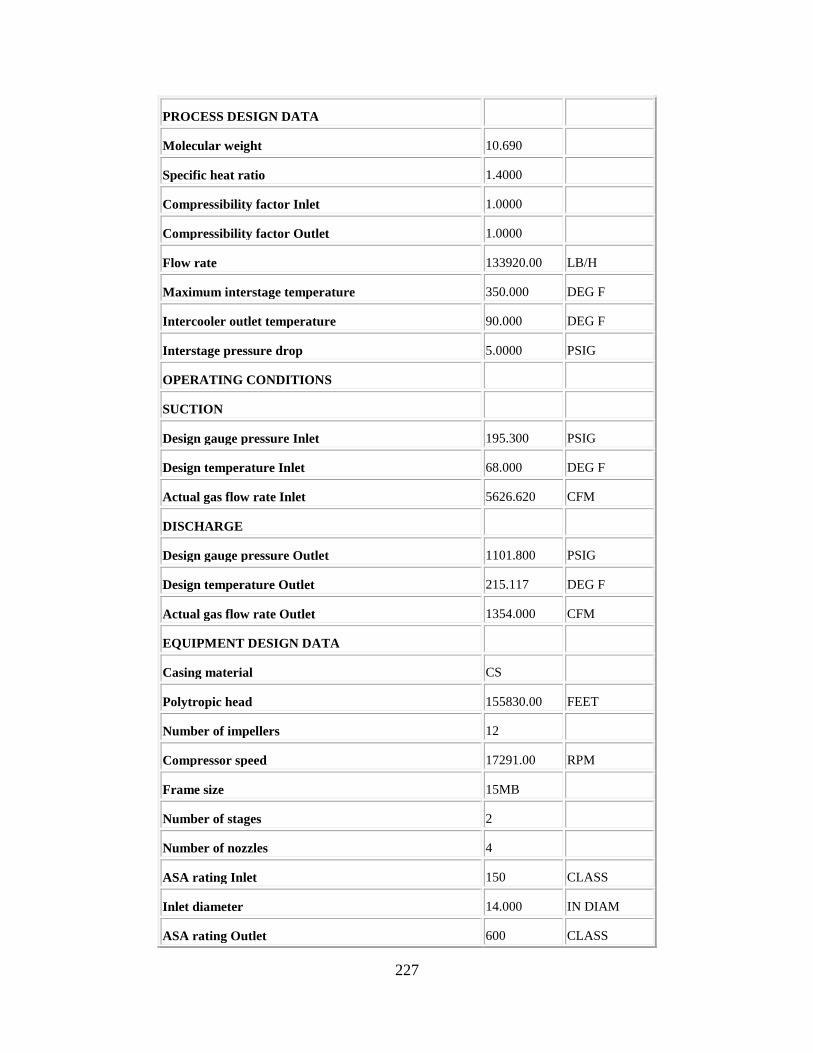
227
PROCESS DESIGN DATA
Molecular weight 10.690
Specific heat ratio 1.4000
Compressibility factor Inlet 1.0000
Compressibility factor Outlet 1.0000
Flow rate 133920.00 LB/H
Maximum interstage temperature 350.000 DEG F
Intercooler outlet temperature 90.000 DEG F
Interstage pressure drop 5.0000 PSIG
OPERATING CONDITIONS
SUCTION
Design gauge pressure Inlet 195.300 PSIG
Design temperature Inlet 68.000 DEG F
Actual gas flow rate Inlet 5626.620 CFM
DISCHARGE
Design gauge pressure Outlet 1101.800 PSIG
Design temperature Outlet 215.117 DEG F
Actual gas flow rate Outlet 1354.000 CFM
EQUIPMENT DESIGN DATA
Casing material CS
Polytropic head 155830.00 FEET
Number of impellers 12
Compressor speed 17291.00 RPM
Frame size 15MB
Number of stages 2
Number of nozzles 4
ASA rating Inlet 150 CLASS
Inlet diameter 14.000 IN DIAM
ASA rating Outlet 600 CLASS

228
Outlet diameter 8.0000 INCHES
Driver power 21606.37 HP
Driver speed 1800.000 RPM
Motor type ODP
Driver type MOTOR
Gear reducer type YES
Lube oil system YES
INTERCOOLER(S), AFTERCOOLER
Intercooler required NO
Aftercooler required NO
GENERAL DESIGN DATA
Power per gas flow rate 3.8400 HP/CFM
Power per stage 10803.18 HP/STAGE
Power per liquid flow rate 6.1982 LB/H/HP
Differential pressure 906.500 PSIG
Pressure ratio Output to Input 5.3167 P2/P1
WEIGHT DATA
Flanges 230 LBS
Gear reducer 46400 LBS
Motor 42200 LBS
Compressor 20500 LBS
Fittings and miscellaneous 1700 LBS
Total weight 111000 LBS
VENDOR COST DATA
MATERIAL COST INCLUDES DRIVER
Motor cost 1296664 DOLLARS
Lube and seal oil cost 801864 DOLLARS
Testing cost 221499 DOLLARS
Fabrication labor 15518 HOURS

229
Material cost 1543136 DOLLARS
Shop labor cost 409671 DOLLARS
Shop overhead cost 528476 DOLLARS
Office overhead cost 446631 DOLLARS
Profit 527024 DOLLARS
Total cost 4478301 DOLLARS
Cost per unit weight 40.345 USD/LBS
Cost per unit gas flow rate 795.913 USD/CFM
Cost per unit power 207.268 USD/HP
Cost per unit flow rate 120384.41 USD/LB/H
Cost per stage 373191.66 DOLLARS
Summary Costs
Item Material(USD) Manpower(USD) Manhours
Equipment&Setting 4478300. 39272. 1248
Piping 58150. 18171. 591
Civil 17575. 10074. 402
Structural Steel 0. 0. 0
Instrumentation 48032. 25744. 824
Electrical 144437. 65135. 2162
Insulation 3938. 3435. 147
Paint 1202. 2667. 116
Subtotal 4751634 164498 5490
Total material and manpower cost=USD 4916100.
ITEM REPORT
Processing Date : Mon Apr 17 02:11:49 PM 2017
Version : Aspen Process Economic Analyzer 34.1.0(Build 3457)
List of Items :
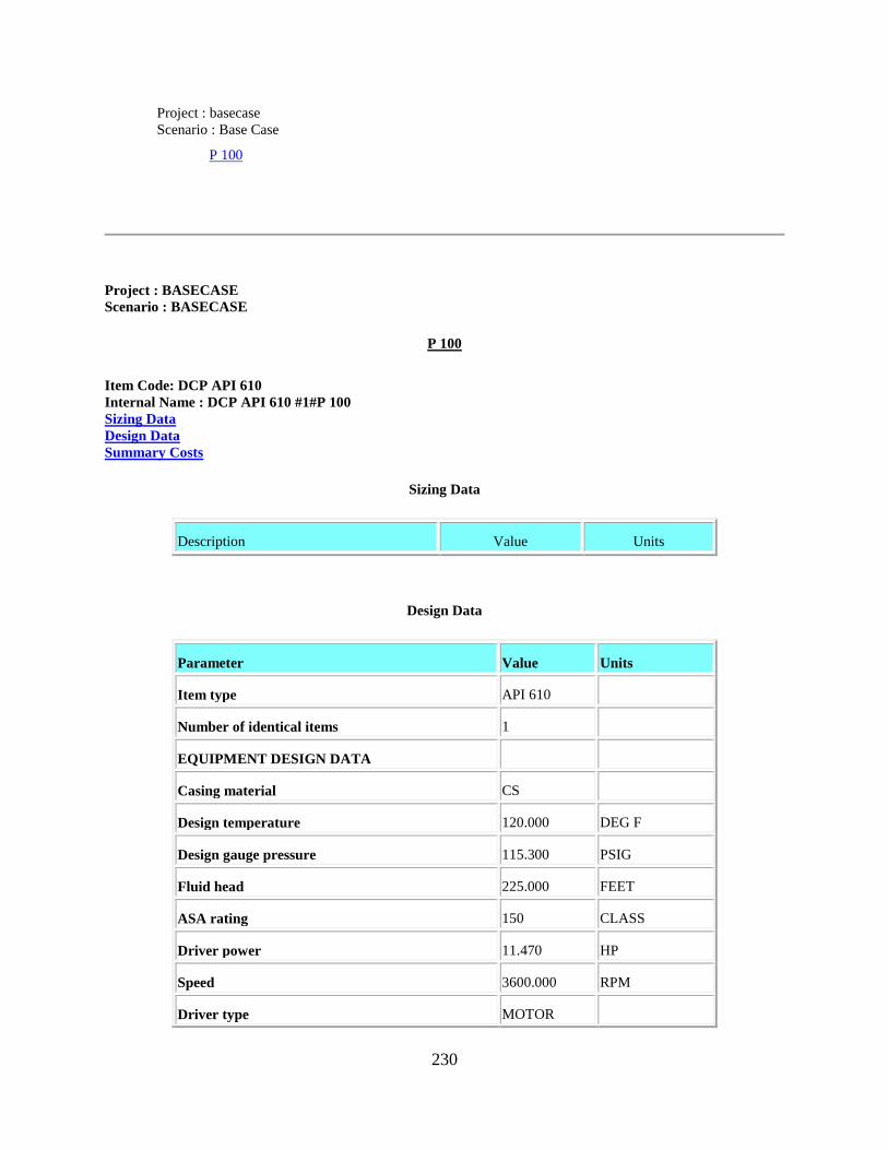
230
Project : basecase
Scenario : Base Case
P 100
Project : BASECASE
Scenario : BASECASE
P 100
Item Code: DCP API 610
Internal Name : DCP API 610 #1#P 100
Sizing Data
Design Data
Summary Costs
Sizing Data
Description Value Units
Design Data
Parameter Value Units
Item type API 610
Number of identical items 1
EQUIPMENT DESIGN DATA
Casing material CS
Design temperature 120.000 DEG F
Design gauge pressure 115.300 PSIG
Fluid head 225.000 FEET
ASA rating 150 CLASS
Driver power 11.470 HP
Speed 3600.000 RPM
Driver type MOTOR

231
Motor type TEFC
Pump efficiency 75.000 PERCENT
SEAL DATA
Seal type SNGL
Primary seal pipe plan 11
Pipe plan pipe type WELD
Pipe plan material type A 106
PROCESS DESIGN DATA
Liquid flow rate 272.630 GPM
Fluid specific gravity 1.0000
Fluid viscosity 1.0000 CPOISE
Power per liquid flow rate 0.042072 HP/GPM
Liquid flow rate times head 61341 GPM -FT
WEIGHT DATA
Pump 320 LBS
Motor 230 LBS
Base plate 70 LBS
Fittings and miscellaneous 60 LBS
Total weight 680 LBS
VENDOR COST DATA
Motor cost 895 DOLLARS
Material cost 3012 DOLLARS
Shop labor cost 6620 DOLLARS
Shop overhead cost 6752 DOLLARS
Office overhead cost 2938 DOLLARS
Profit 3283 DOLLARS
Total cost 23500 DOLLARS
Cost per unit weight 34.559 USD/LBS
Cost per unit liquid flow rate 86.197 USD/GPM

232
Cost per unit power 2048.823 USD/HP
Summary Costs
Item Material(USD) Manpower(USD) Manhours
Equipment&Setting 23500. 777. 25
Piping 12722. 6268. 204
Civil 305. 751. 31
Structural Steel 0. 0. 0
Instrumentation 9571. 2498. 80
Electrical 1200. 1497. 50
Insulation 0. 0. 0
Paint 629. 1311. 58
Subtotal 47927 13102 448
Total material and manpower cost=USD 61000.
ITEM REPORT
Processing Date : Mon Apr 17 02:12:32 PM 2017
Version : Aspen Process Economic Analyzer 34.1.0(Build 3457)
List of Items :
Project : basecase
Scenario : Base Case
P 101
Project : BASECASE
Scenario : BASECASE
P 101
Item Code: DCP API 610
Internal Name : DCP API 610 #1#P 101
Sizing Data

233
Design Data
Summary Costs
Sizing Data
Description Value Units
Design Data
Parameter Value Units
Item type API 610
Number of identical items 1
EQUIPMENT DESIGN DATA
Casing material CS
Design temperature 120.000 DEG F
Design gauge pressure 65.300 PSIG
Fluid head 225.000 FEET
ASA rating 150 CLASS
Driver power 23.140 HP
Speed 3600.000 RPM
Driver type MOTOR
Motor type TEFC
Pump efficiency 75.000 PERCENT
SEAL DATA
Seal type SNGL
Primary seal pipe plan 11
Pipe plan pipe type WELD
Pipe plan material type A 106
PROCESS DESIGN DATA
Liquid flow rate 275.560 GPM
Fluid specific gravity 1.0000

234
Fluid viscosity 1.0000 CPOISE
Power per liquid flow rate 0.083974 HP/GPM
Liquid flow rate times head 62001 GPM -FT
WEIGHT DATA
Pump 320 LBS
Motor 320 LBS
Base plate 70 LBS
Fittings and miscellaneous 60 LBS
Total weight 770 LBS
VENDOR COST DATA
Motor cost 1529 DOLLARS
Material cost 3012 DOLLARS
Shop labor cost 6620 DOLLARS
Shop overhead cost 6752 DOLLARS
Office overhead cost 3046 DOLLARS
Profit 3341 DOLLARS
Total cost 24300 DOLLARS
Cost per unit weight 31.558 USD/LBS
Cost per unit liquid flow rate 88.184 USD/GPM
Cost per unit power 1050.130 USD/HP
Summary Costs
Item Material(USD) Manpower(USD) Manhours
Equipment&Setting 24300. 891. 28
Piping 12722. 6268. 204
Civil 442. 945. 39
Structural Steel 0. 0. 0
Instrumentation 9571. 2498. 80

235
Electrical 1208. 1500. 50
Insulation 0. 0. 0
Paint 629. 1311. 58
Subtotal 48872 13413 459
Total material and manpower cost=USD 62300.
ITEM REPORT
Processing Date : Mon Apr 17 02:13:00 PM 2017
Version : Aspen Process Economic Analyzer 34.1.0(Build 3457)
List of Items :
Project : basecase
Scenario : Base Case
K 100 TE
Project : BASECASE
Scenario : BASECASE
K 100 TE
Item Code: DTURTURBOEXP
Internal Name : DTURTURBOEXP #1#K 100 TE
Sizing Data
Design Data
Summary Costs
Sizing Data
Description Value Units
Design Data
Parameter Value Units
Item type TURBOEXP
Number of identical items 1

236
EQUIPMENT DESIGN DATA
Material A3003
Actual gas flow rate Inlet 4413.000 CFM
Design gauge pressure Inlet 425.300 PSIG
Design temperature Inlet 70.000 DEG F
Design gauge pressure Outlet 45.300 PSIG
Power output 9654.221 HP
Molecular weight 17.720
Specific heat ratio 1.4000
Compressibility factor Inlet 1.0000
Isentropic efficiency 75.000 PERCENT
Number of spare cartridges 0
WEIGHT DATA
Total weight 78100 LBS
VENDOR COST DATA
Total cost 2746701 DOLLARS
Cost per unit weight 35.169 USD/LBS
Summary Costs
Item Material(USD) Manpower(USD) Manhours
Equipment&Setting 2746700. 25393. 808
Piping 198883. 41577. 1342
Civil 20386. 11554. 460
Structural Steel 0. 0. 0
Instrumentation 74340. 15594. 500
Electrical 0. 0. 0
Insulation 14881. 6988. 306
Paint 40. 103. 5

237
Subtotal 3055230 101209 3421
Total material and manpower cost=USD 3156400.
ITEM REPORT
Processing Date : Mon Apr 17 02:13:28 PM 2017
Version : Aspen Process Economic Analyzer 34.1.0(Build 3457)
List of Items :
Project : basecase
Scenario : Base Case
K 102 TE
Project : BASECASE
Scenario : BASECASE
K 102 TE
Item Code: DTURTURBOEXP
Internal Name : DTURTURBOEXP #1#K 102 TE
Sizing Data
Design Data
Summary Costs
Sizing Data
Description Value Units
Design Data
Parameter Value Units
Item type TURBOEXP
Number of identical items 1
EQUIPMENT DESIGN DATA
Material A3003
Actual gas flow rate Inlet 1199.000 CFM

238
Design gauge pressure Inlet 1101.800 PSIG
Design temperature Inlet 70.000 DEG F
Design gauge pressure Outlet 45.300 PSIG
Power output 8683.142 HP
Molecular weight 17.600
Specific heat ratio 1.4000
Compressibility factor Inlet 1.0000
Isentropic efficiency 75.000 PERCENT
Number of spare cartridges 0
WEIGHT DATA
Total weight 71100 LBS
VENDOR COST DATA
Total cost 2478301 DOLLARS
Cost per unit weight 34.857 USD/LBS
Summary Costs
Item Material(USD) Manpower(USD) Manhours
Equipment&Setting 2478300. 23549. 750
Piping 152270. 34869. 1123
Civil 18559. 10526. 419
Structural Steel 0. 0. 0
Instrumentation 62140. 15594. 500
Electrical 0. 0. 0
Insulation 15344. 7481. 328
Paint 40. 103. 5
Subtotal 2726653 92122 3125
Total material and manpower cost=USD 2818800.

239
HYSYS Model Printout

PENNSYLVANIA STATE UNIVEBedford, MAUSA
Case Name: NEWEST_HYSYS.hsc
Unit Set: Field
Date/Time: Mon Apr 17 17:18:58 2017
Conversion Reactor: Prereformer
CONNECTIONS
Inlet Stream Connections
Stream Name From Unit OperationReactor Feed MIX-100Mixer
Outlet Stream Connections
Stream Name To Unit Operation8 Expander: K-100
x
Energy Stream Connections
Stream Name From Unit Operation
PARAMETERS
Physical Parameters Optional Heat Transfer
Delta P Vessel Volume Duty Energy Stream0.0000 psi 10.00 ft3 * 0.0000 Btu/hr
User Variables
Conversion Reactor: MeOH Synth
CONNECTIONS
Inlet Stream Connections
Stream Name From Unit Operation14-5 E-105Heat Exchanger
Outlet Stream Connections
Stream Name To Unit Operation16 Expander: K-102
xxx
Energy Stream Connections
Stream Name From Unit OperationQ-103
PARAMETERS
Physical Parameters Optional Heat Transfer
Delta P Vessel Volume Duty Energy Stream0.0000 psi 20.00 ft3 * -1.002e+008 Btu/hr Q-103
User Variables
Component Splitter: ATU
CONNECTIONS
Inlet Stream
Aspen Technology Inc. Aspen HYSYS Version 8.8 (34.0.1.8909) Page 1 of 22
1
2
3
4
5
6
7
8
9
10
11
12
13
14
15
16
17
18
19
20
21
22
23
24
25
26
27
28
29
30
31
32
33
34
35
36
37
38
39
40
41
42
43
44
45
46
47
48
49
50
51
52
53
54
55
56
57
58
59
60
61
62
63
* Specified by user.Licensed to: PENNSYLVANIA STATE UNIVE

PENNSYLVANIA STATE UNIVEBedford, MAUSA
Case Name: NEWEST_HYSYS.hsc
Unit Set: Field
Date/Time: Mon Apr 17 17:18:58 2017
Component Splitter: ATU (continued)
CONNECTIONS
STREAM NAME FROM UNIT OPERATION
3 MRUComponent Splitter
4
Outlet Stream
STREAM NAME TO UNIT OPERATION
6 Heat Exchanger: E-100
5
Energy Stream
STREAM NAME FROM UNIT OPERATION
Q-100
PARAMETERS
Stream Specifications
Overhead Pressure: 400.0 psia Overhead Vapour Fraction: 1.0000
Bottoms Pressure: 400.0 psia Bottoms Vapour Fraction: 0.0000
SPLITS
Component Fraction To Overhead
Component
Methane
H2O
Ethane
CO2
Nitrogen
Propane
i-Butane
n-Butane
i-Pentane
n-Pentane
Cyclohexane
CO
Hydrogen
Mercury
H2S
MDEAmine
Methanol
Ethanol
M-Formate
Ammonia
Air
Oxygen
Split Basis
Molar
Molar
Molar
Molar
Molar
Molar
Molar
Molar
Molar
Molar
Molar
Molar
Molar
Molar
Molar
Molar
Molar
Molar
Molar
Molar
Molar
Molar
Split Type
FeedFrac. to Products
FeedFrac. to Products
FeedFrac. to Products
FeedFrac. to Products
FeedFrac. to Products
FeedFrac. to Products
FeedFrac. to Products
FeedFrac. to Products
FeedFrac. to Products
FeedFrac. to Products
FeedFrac. to Products
FeedFrac. to Products
FeedFrac. to Products
FeedFrac. to Products
FeedFrac. to Products
FeedFrac. to Products
FeedFrac. to Products
FeedFrac. to Products
FeedFrac. to Products
FeedFrac. to Products
FeedFrac. to Products
FeedFrac. to Products
6
1.0000 *
0.0000 *
1.0000 *
1.0000 *
1.0000 *
1.0000 *
1.0000 *
1.0000 *
1.0000 *
1.0000 *
1.0000 *
1.0000 *
1.0000 *
0.0000 *
0.0000 *
0.0000 *
0.0000 *
0.0000 *
0.0000 *
0.0000 *
0.0000 *
0.0000 *
User Variables
Aspen Technology Inc. Aspen HYSYS Version 8.8 (34.0.1.8909) Page 2 of 22
1
2
3
4
5
6
7
8
9
10
11
12
13
14
15
16
17
18
19
20
21
22
23
24
25
26
27
28
29
30
31
32
33
34
35
36
37
38
39
40
41
42
43
44
45
46
47
48
49
50
51
52
53
54
55
56
57
58
59
60
61
62
63
* Specified by user.Licensed to: PENNSYLVANIA STATE UNIVE

PENNSYLVANIA STATE UNIVEBedford, MAUSA
Case Name: NEWEST_HYSYS.hsc
Unit Set: Field
Date/Time: Mon Apr 17 17:18:58 2017
Component Splitter: MRU
CONNECTIONS
Inlet Stream
STREAM NAME FROM UNIT OPERATION
1
Outlet Stream
STREAM NAME TO UNIT OPERATION
3 Component Splitter: ATU
2
Energy Stream
STREAM NAME FROM UNIT OPERATION
Q-101
PARAMETERS
Stream Specifications
Overhead Pressure: 400.0 psia Overhead Vapour Fraction: 1.0000
Bottoms Pressure: 400.0 psia Bottoms Vapour Fraction: 0.0000 *
SPLITS
Component Fraction To Overhead
Component
Methane
H2O
Ethane
CO2
Nitrogen
Propane
i-Butane
n-Butane
i-Pentane
n-Pentane
Cyclohexane
CO
Hydrogen
Mercury
H2S
MDEAmine
Methanol
Ethanol
M-Formate
Ammonia
Air
Oxygen
Split Basis
Molar
Molar
Molar
Molar
Molar
Molar
Molar
Molar
Molar
Molar
Molar
Molar
Molar
Molar
Molar
Molar
Molar
Molar
Molar
Molar
Molar
Molar
Split Type
FeedFrac. to Products
FeedFrac. to Products
FeedFrac. to Products
FeedFrac. to Products
FeedFrac. to Products
FeedFrac. to Products
FeedFrac. to Products
FeedFrac. to Products
FeedFrac. to Products
FeedFrac. to Products
FeedFrac. to Products
FeedFrac. to Products
FeedFrac. to Products
FeedFrac. to Products
FeedFrac. to Products
FeedFrac. to Products
FeedFrac. to Products
FeedFrac. to Products
FeedFrac. to Products
FeedFrac. to Products
FeedFrac. to Products
FeedFrac. to Products
3
1.0000 *
1.0000 *
1.0000 *
1.0000 *
1.0000 *
1.0000 *
1.0000 *
1.0000 *
1.0000 *
1.0000 *
1.0000 *
1.0000 *
1.0000 *
0.0000 *
1.0000 *
1.0000 *
0.0000 *
0.0000 *
0.0000 *
0.0000 *
0.0000 *
0.0000 *
User Variables
Aspen Technology Inc. Aspen HYSYS Version 8.8 (34.0.1.8909) Page 3 of 22
1
2
3
4
5
6
7
8
9
10
11
12
13
14
15
16
17
18
19
20
21
22
23
24
25
26
27
28
29
30
31
32
33
34
35
36
37
38
39
40
41
42
43
44
45
46
47
48
49
50
51
52
53
54
55
56
57
58
59
60
61
62
63
* Specified by user.Licensed to: PENNSYLVANIA STATE UNIVE

PENNSYLVANIA STATE UNIVEBedford, MAUSA
Case Name: NEWEST_HYSYS.hsc
Unit Set: Field
Date/Time: Mon Apr 17 17:18:58 2017
Expander: K-100
CONNECTIONS
Inlet Stream
STREAM NAME FROM UNIT OPERATION
8 PrereformerConversion Reactor
Outlet Stream
STREAM NAME TO UNIT OPERATION
8-1 MIX-101Mixer
Energy Stream
STREAM NAME TO UNIT OPERATION
Q-105
PARAMETERS
Duty: 1.0359e+04 hp Speed: ---
Adiabatic Eff.: 75.00 PolyTropic Eff.: 73.29
Adiabatic Head: 1.382e+005 ft Polytropic Head: 1.414e+005 ft
Adiabatic Fluid Head: 1.382e+005 lbf-ft/lbm Polytropic Fluid Head: 1.414e+005 lbf-ft/lbm
Polytropic Exp. 1.123 Isentropic Exp. 1.147 Poly Head Factor 0.8136
User Variables
Expander: K-102
CONNECTIONS
Inlet Stream
STREAM NAME FROM UNIT OPERATION
16 MeOH SynthConversion Reactor
Outlet Stream
STREAM NAME TO UNIT OPERATION
16-1 E-104Heat Exchanger
Energy Stream
STREAM NAME TO UNIT OPERATION
Q-111
PARAMETERS
Duty: 1.0944e+04 hp Speed: ---
Adiabatic Eff.: 75.00 PolyTropic Eff.: 72.23
Adiabatic Head: 2.173e+005 ft Polytropic Head: 2.257e+005 ft
Adiabatic Fluid Head: 2.173e+005 lbf-ft/lbm Polytropic Fluid Head: 2.257e+005 lbf-ft/lbm
Polytropic Exp. 1.124 Isentropic Exp. 1.154 Poly Head Factor 0.9779
User Variables
Compressor: K-104
DESIGN
Aspen Technology Inc. Aspen HYSYS Version 8.8 (34.0.1.8909) Page 4 of 22
1
2
3
4
5
6
7
8
9
10
11
12
13
14
15
16
17
18
19
20
21
22
23
24
25
26
27
28
29
30
31
32
33
34
35
36
37
38
39
40
41
42
43
44
45
46
47
48
49
50
51
52
53
54
55
56
57
58
59
60
61
62
63
* Specified by user.Licensed to: PENNSYLVANIA STATE UNIVE

PENNSYLVANIA STATE UNIVEBedford, MAUSA
Case Name: NEWEST_HYSYS.hsc
Unit Set: Field
Date/Time: Mon Apr 17 17:18:58 2017
Compressor: K-104 (continued)
Connections
Inlet Stream
STREAM NAME FROM UNIT OPERATION
14 V-101Separator
Outlet Stream
STREAM NAME TO UNIT OPERATION
14-1 E-103Heat Exchanger
Energy Stream
STREAM NAME FROM UNIT OPERATION
Q-121
Parameters
Speed: --- Duty: 1.8589e+04 hp
Adiabatic Eff.: 75.00 PolyTropic Eff.: 79.97
Adiabatic Head: 2.077e+005 ft Polytropic Head: 2.214e+005 ft
Adiabatic Fluid Head: 2.077e+005 lbf-ft/lbm Polytropic Fluid Head: 2.214e+005 lbf-ft/lbm
Polytropic Exp. 1.513 Isentropic Exp. 1.376 Poly Head Factor 1.002
User Variables
Compressor: K-105
DESIGN
Connections
Inlet Stream
STREAM NAME FROM UNIT OPERATION
14-2 E-103Heat Exchanger
Outlet Stream
STREAM NAME TO UNIT OPERATION
14-3 E-102Heat Exchanger
Energy Stream
STREAM NAME FROM UNIT OPERATION
Q-123
Parameters
Speed: --- Duty: 2.1408e+04 hp
Adiabatic Eff.: 75.00 PolyTropic Eff.: 79.76
Adiabatic Head: 2.391e+005 ft Polytropic Head: 2.543e+005 ft
Adiabatic Fluid Head: 2.391e+005 lbf-ft/lbm Polytropic Fluid Head: 2.543e+005 lbf-ft/lbm
Polytropic Exp. 1.517 Isentropic Exp. 1.380 Poly Head Factor 1.008
User Variables
Aspen Technology Inc. Aspen HYSYS Version 8.8 (34.0.1.8909) Page 5 of 22
1
2
3
4
5
6
7
8
9
10
11
12
13
14
15
16
17
18
19
20
21
22
23
24
25
26
27
28
29
30
31
32
33
34
35
36
37
38
39
40
41
42
43
44
45
46
47
48
49
50
51
52
53
54
55
56
57
58
59
60
61
62
63
* Specified by user.Licensed to: PENNSYLVANIA STATE UNIVE

PENNSYLVANIA STATE UNIVEBedford, MAUSA
Case Name: NEWEST_HYSYS.hsc
Unit Set: Field
Date/Time: Mon Apr 17 17:18:58 2017
Distillation: T-103
CONNECTIONS
Inlet Stream
STREAM NAME Stage FROM UNIT OPERATION
Q-11921
Reboiler30__Main Tower TEE-101Tee
Outlet Stream
STREAM NAME Stage TO UNIT OPERATION
Q-1182827
CondenserReboilerCondenser
MIX-103
MIX-104
Mixer
Mixer
MONITOR
Specifications Summary
Specified Value Current Value Wt. Error
Reflux Ratio 4.500 * 4.500 1.092e-008
Reflux Rate 4576 lbmole/hr * 5395 lbmole/hr 0.1790
Comp Fraction 1.400e-003 * 1.022e-003 -9.343e-002
Comp Fraction - 2 3.475e-025 * 2.822e-003 2.822e-003
28 Rate 474.5 lbmole/hr * 1107 lbmole/hr 1.333
27 Rate 1220 lbmole/hr * 1199 lbmole/hr -1.748e-002
Comp Fraction - 3 9.538e-002 * --- ---
Comp Flow 100.0 lb/hr * 100.1 lb/hr 6.630e-004
Wt. Tol. Abs. Tol. Active Estimate Used
Reflux Ratio 1.000e-002 1.000e-002 On On On
Reflux Rate 1.000e-002 2.205 lbmole/hr Off On Off
Comp Fraction 1.000e-002 1.000e-003 Off On Off
Comp Fraction - 2 1.000e-002 1.000e-003 Off On Off
28 Rate 1.000e-002 2.205 lbmole/hr Off On Off
27 Rate 1.000e-002 2.205 lbmole/hr Off On Off
Comp Fraction - 3 1.000e-002 1.000e-003 Off On Off
Comp Flow 1.000e-002 2.205 lb/hr On On On
SPECS
Column Specification Parameters
Reflux Ratio
Fix/Rang: Ranged Prim/Alter: Primary Lower Bnd: 5.000 * Upper Bnd: 5.000e-002 *
Stage: Condenser Flow Basis: Molar Liquid Spec: ---
Reflux Rate
Fix/Rang: Fixed Prim/Alter: Primary Lower Bnd: --- Upper Bnd: ---
Stage: Condenser Flow Basis: Molar Liquid Spec: ---
Comp Fraction
Fix/Rang: Ranged Prim/Alter: Primary Lower Bnd: --- Upper Bnd: ---
Stage: Flow Basis: Mass Fraction Phase: Liquid
Components:H2O Ethanol Ammonia
CO2 CO M-Formate
Comp Fraction - 2
Fix/Rang: Ranged Prim/Alter: Primary Lower Bnd: --- Upper Bnd: ---
Stage: Flow Basis: Mole Fraction Phase: Liquid
Components: Methanol
Aspen Technology Inc. Aspen HYSYS Version 8.8 (34.0.1.8909) Page 6 of 22
1
2
3
4
5
6
7
8
9
10
11
12
13
14
15
16
17
18
19
20
21
22
23
24
25
26
27
28
29
30
31
32
33
34
35
36
37
38
39
40
41
42
43
44
45
46
47
48
49
50
51
52
53
54
55
56
57
58
59
60
61
62
63
* Specified by user.Licensed to: PENNSYLVANIA STATE UNIVE
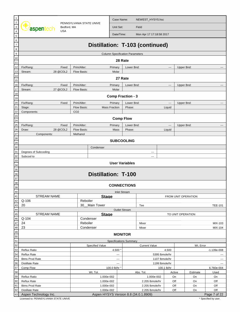
PENNSYLVANIA STATE UNIVEBedford, MAUSA
Case Name: NEWEST_HYSYS.hsc
Unit Set: Field
Date/Time: Mon Apr 17 17:18:58 2017
Distillation: T-103 (continued)Column Specification Parameters
28 Rate
Fix/Rang: Fixed Prim/Alter: Primary Lower Bnd: --- Upper Bnd: ---
Stream: 28 @COL2 Flow Basis: Molar
27 Rate
Fix/Rang: Fixed Prim/Alter: Primary Lower Bnd: --- Upper Bnd: ---
Stream: 27 @COL2 Flow Basis: Molar
Comp Fraction - 3
Fix/Rang: Fixed Prim/Alter: Primary Lower Bnd: --- Upper Bnd: ---
Stage: Flow Basis: Mass Fraction Phase: Liquid
Components: CO2
Comp Flow
Fix/Rang: Fixed Prim/Alter: Primary Lower Bnd: --- Upper Bnd: ---
Draw: 28 @COL2 Flow Basis: Mass Phase: Liquid
Components: Methanol
SUBCOOLING
Degrees of Subcooling
Subcool to
Condenser
---
---
User Variables
Distillation: T-100
CONNECTIONS
Inlet Stream
STREAM NAME Stage FROM UNIT OPERATION
Q-10620
Reboiler30__Main Tower TEE-101Tee
Outlet Stream
STREAM NAME Stage TO UNIT OPERATION
Q-1042423
CondenserReboilerCondenser
MIX-103
MIX-104
Mixer
Mixer
MONITOR
Specifications Summary
Specified Value Current Value Wt. Error
Reflux Ratio 4.500 * 4.500 -1.139e-008
Reflux Rate --- 5395 lbmole/hr ---
Btms Prod Rate --- 1107 lbmole/hr ---
Distillate Rate --- 1199 lbmole/hr ---
Comp Flow 100.0 lb/hr * 100.1 lb/hr 6.760e-004
Wt. Tol. Abs. Tol. Active Estimate Used
Reflux Ratio 1.000e-002 1.000e-002 On On On
Reflux Rate 1.000e-002 2.205 lbmole/hr Off On Off
Btms Prod Rate 1.000e-002 2.205 lbmole/hr Off On Off
Distillate Rate 1.000e-002 2.205 lbmole/hr Off On Off
Aspen Technology Inc. Aspen HYSYS Version 8.8 (34.0.1.8909) Page 7 of 22
1
2
3
4
5
6
7
8
9
10
11
12
13
14
15
16
17
18
19
20
21
22
23
24
25
26
27
28
29
30
31
32
33
34
35
36
37
38
39
40
41
42
43
44
45
46
47
48
49
50
51
52
53
54
55
56
57
58
59
60
61
62
63
* Specified by user.Licensed to: PENNSYLVANIA STATE UNIVE
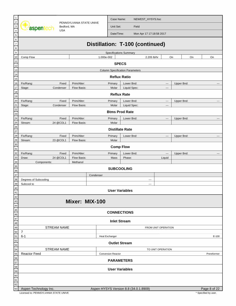
PENNSYLVANIA STATE UNIVEBedford, MAUSA
Case Name: NEWEST_HYSYS.hsc
Unit Set: Field
Date/Time: Mon Apr 17 17:18:58 2017
Distillation: T-100 (continued)Specifications Summary
Comp Flow 1.000e-002 2.205 lb/hr On On On
SPECS
Column Specification Parameters
Reflux Ratio
Fix/Rang: Fixed Prim/Alter: Primary Lower Bnd: --- Upper Bnd: ---
Stage: Condenser Flow Basis: Molar Liquid Spec: ---
Reflux Rate
Fix/Rang: Fixed Prim/Alter: Primary Lower Bnd: --- Upper Bnd: ---
Stage: Condenser Flow Basis: Molar Liquid Spec: ---
Btms Prod Rate
Fix/Rang: Fixed Prim/Alter: Primary Lower Bnd: --- Upper Bnd: ---
Stream: 24 @COL1 Flow Basis: Molar
Distillate Rate
Fix/Rang: Fixed Prim/Alter: Primary Lower Bnd: --- Upper Bnd: ---
Stream: 23 @COL1 Flow Basis: Molar
Comp Flow
Fix/Rang: Fixed Prim/Alter: Primary Lower Bnd: --- Upper Bnd: ---
Draw: 24 @COL1 Flow Basis: Mass Phase: Liquid
Components: Methanol
SUBCOOLING
Degrees of Subcooling
Subcool to
Condenser
---
---
User Variables
Mixer: MIX-100
CONNECTIONS
Inlet Stream
STREAM NAME FROM UNIT OPERATION
76-1 E-100Heat Exchanger
Outlet Stream
STREAM NAME TO UNIT OPERATION
Reactor Feed PrereformerConversion Reactor
PARAMETERS
User Variables
Aspen Technology Inc. Aspen HYSYS Version 8.8 (34.0.1.8909) Page 8 of 22
1
2
3
4
5
6
7
8
9
10
11
12
13
14
15
16
17
18
19
20
21
22
23
24
25
26
27
28
29
30
31
32
33
34
35
36
37
38
39
40
41
42
43
44
45
46
47
48
49
50
51
52
53
54
55
56
57
58
59
60
61
62
63
* Specified by user.Licensed to: PENNSYLVANIA STATE UNIVE

PENNSYLVANIA STATE UNIVEBedford, MAUSA
Case Name: NEWEST_HYSYS.hsc
Unit Set: Field
Date/Time: Mon Apr 17 17:18:58 2017
Mixer: MIX-101
CONNECTIONS
Inlet Stream
STREAM NAME FROM UNIT OPERATION
8-113-1
K-100
RCY-2
Expander
Recycle
Outlet Stream
STREAM NAME TO UNIT OPERATION
9 E-107Heat Exchanger
PARAMETERS
User Variables
Mixer: MIX-103
CONNECTIONS
Inlet Stream
STREAM NAME FROM UNIT OPERATION
222412
T-103
T-100
TEE-100
Distillation
Distillation
Tee
Outlet Stream
STREAM NAME TO UNIT OPERATION
27 P-100Pump
PARAMETERS
User Variables
Mixer: MIX-104
CONNECTIONS
Inlet Stream
STREAM NAME FROM UNIT OPERATION
2123
T-103
T-100
Distillation
Distillation
Outlet Stream
STREAM NAME TO UNIT OPERATION
29 P-101Pump
PARAMETERS
User Variables
Aspen Technology Inc. Aspen HYSYS Version 8.8 (34.0.1.8909) Page 9 of 22
1
2
3
4
5
6
7
8
9
10
11
12
13
14
15
16
17
18
19
20
21
22
23
24
25
26
27
28
29
30
31
32
33
34
35
36
37
38
39
40
41
42
43
44
45
46
47
48
49
50
51
52
53
54
55
56
57
58
59
60
61
62
63
* Specified by user.Licensed to: PENNSYLVANIA STATE UNIVE

PENNSYLVANIA STATE UNIVEBedford, MAUSA
Case Name: NEWEST_HYSYS.hsc
Unit Set: Field
Date/Time: Mon Apr 17 17:18:58 2017
Recycle: RCY-2
CONNECTIONS
Inlet Stream
Stream Name From Unit Operation
13 TEE-100Tee
Outlet Stream
Stream Name To Unit Operation
13-1 MIX-101Mixer
TOLERANCE
Vapour Fraction: 10.00 * Temperature: 10.00 * Pressure: 10.00 *
Flow: 0.1000 * Enthalpy: 10.00 * Composition: 0.1000 *
NUMERICAL
Acceleration Type: Wegstein Iteration Type: Nested
Maximum Iterations: 10 * Iteration Count: 0 *
Wegstein Count: 3 * Q Minimum: -20.00 * Q Maximum: 0.0000 *
Iteration History
Iteration
0 *
Variable
Converged
Outlet Value
---
Inlet Value
---
User Variables
Recycle: RCY-1
CONNECTIONS
Inlet Stream
Stream Name From Unit Operation
17 V-100Separator
Outlet Stream
Stream Name To Unit Operation
17-1
TOLERANCE
Vapour Fraction: 10.00 * Temperature: 10.00 * Pressure: 10.00 *
Flow: 10.00 * Enthalpy: 10.00 * Composition: 10.00 *
NUMERICAL
Acceleration Type: Wegstein Iteration Type: Nested
Maximum Iterations: 10 * Iteration Count: 0 *
Wegstein Count: 3 * Q Minimum: -20.00 * Q Maximum: 0.0000 *
Iteration History
Iteration
1 *
Variable
Converged
Outlet Value
---
Inlet Value
---
User Variables
Aspen Technology Inc. Aspen HYSYS Version 8.8 (34.0.1.8909) Page 10 of 22
1
2
3
4
5
6
7
8
9
10
11
12
13
14
15
16
17
18
19
20
21
22
23
24
25
26
27
28
29
30
31
32
33
34
35
36
37
38
39
40
41
42
43
44
45
46
47
48
49
50
51
52
53
54
55
56
57
58
59
60
61
62
63
* Specified by user.Licensed to: PENNSYLVANIA STATE UNIVE

PENNSYLVANIA STATE UNIVEBedford, MAUSA
Case Name: NEWEST_HYSYS.hsc
Unit Set: Field
Date/Time: Mon Apr 17 17:18:58 2017
Plug Flow Reactor: Steam Reformer
CONNECTIONS
Inlet Stream
STREAM NAME FROM UNIT OPERATION
9-2 FH-100Fired Heater
Outlet Stream
STREAM NAME TO UNIT OPERATION
10 E-100Heat Exchanger
Energy Stream
STREAM NAME TO UNIT OPERATION
Q-1000
PARAMETERS
Physical Parameters
Type : User Specified Pressure Drop: 0.0000 psi *
Heat Transfer
Type : Direct Q Value Energy Stream : Q-1000 Duty : -2.323e+008 Btu/hr
Dimensions
Total Volume: 1924 ft3 Length: 50.00 ft * Diameter: 7.000 ft * Number of Tubes: 1 *
Wall Thickness: 1.640e-002 ft * Void Fraction: 1.0000 * Void Volume: 1924 ft3
Reaction Info
Reaction Set: Set-1 Initialize From: Current
Integration Information
Number of Segments: 20 * Minimum Step Fraction: 1.0e-06 * Minimum Step Length: 5.0e-05 ft
User Variables
Tee: TEE-100
CONNECTIONS
Inlet Stream
STREAM NAME FROM UNIT OPERATION
11 V-101Separator
Outlet Stream
STREAM NAME TO UNIT OPERATION
1213
MIX-103
RCY-2
Mixer
Recycle
PARAMETERS
12
13
Flow Ratios
0.1397
0.8603
Dynamic Valve Openings
13.97
86.03
Aspen Technology Inc. Aspen HYSYS Version 8.8 (34.0.1.8909) Page 11 of 22
1
2
3
4
5
6
7
8
9
10
11
12
13
14
15
16
17
18
19
20
21
22
23
24
25
26
27
28
29
30
31
32
33
34
35
36
37
38
39
40
41
42
43
44
45
46
47
48
49
50
51
52
53
54
55
56
57
58
59
60
61
62
63
* Specified by user.Licensed to: PENNSYLVANIA STATE UNIVE

PENNSYLVANIA STATE UNIVEBedford, MAUSA
Case Name: NEWEST_HYSYS.hsc
Unit Set: Field
Date/Time: Mon Apr 17 17:18:58 2017
Tee: TEE-100 (continued)
PARAMETERS
Valve Control: Multiple Stream
User Variables
Tee: TEE-101
CONNECTIONS
Inlet Stream
STREAM NAME FROM UNIT OPERATION
18-1 E-102Heat Exchanger
Outlet Stream
STREAM NAME TO UNIT OPERATION
1920
T-103
T-100
Distillation
Distillation
PARAMETERS
19
20
Flow Ratios
0.5000 *
0.5000
Dynamic Valve Openings
50.00
50.00
Valve Control: Multiple Stream
User Variables
Separator: V-100
CONNECTIONS
Inlet Stream
Stream Name From Unit Operation
16-2 Heat Exchanger: E-104
Outlet Stream
Stream Name To Unit Operation
17 Recycle: RCY-1
18 Heat Exchanger: E-102
Energy Stream
Stream Name From Unit Operation
PARAMETERS
Vessel Volume: --- Level SP: 50.00 % Liquid Volume: ---
Vessel Pressure: 30.00 psia Pressure Drop: 0.0000 psi Duty: 0.0000 Btu/hr Heat Transfer Mode: Heating
User Variables
Aspen Technology Inc. Aspen HYSYS Version 8.8 (34.0.1.8909) Page 12 of 22
1
2
3
4
5
6
7
8
9
10
11
12
13
14
15
16
17
18
19
20
21
22
23
24
25
26
27
28
29
30
31
32
33
34
35
36
37
38
39
40
41
42
43
44
45
46
47
48
49
50
51
52
53
54
55
56
57
58
59
60
61
62
63
* Specified by user.Licensed to: PENNSYLVANIA STATE UNIVE

PENNSYLVANIA STATE UNIVEBedford, MAUSA
Case Name: NEWEST_HYSYS.hsc
Unit Set: Field
Date/Time: Mon Apr 17 17:18:58 2017
Separator: V-101
CONNECTIONS
Inlet Stream
Stream Name From Unit Operation
10-4 Heat Exchanger: E-108
Outlet Stream
Stream Name To Unit Operation
14 Compressor: K-104
11 Tee: TEE-100
Energy Stream
Stream Name From Unit Operation
PARAMETERS
Vessel Volume: --- Level SP: 50.00 % Liquid Volume: ---
Vessel Pressure: 30.00 psia Pressure Drop: 0.0000 psi Duty: 0.0000 Btu/hr Heat Transfer Mode: Heating
User Variables
Heat Exchanger: E-100
CONNECTIONS
Tube Side
Inlet
Name
From Op.
Op. Type
Temp
10
Steam Reformer
Plug Flow Reactor
1100.00 F *
Outlet
Name
To Op.
Op. Type
Temp
10-1
E-107
Heat Exchanger
1063.88 F
Shell Side
Inlet
Name
From Op.
Op. Type
Temp
6
ATU
Component Splitter
72.00 F *
Outlet
Name
To Op.
Op. Type
Temp
6-1
MIX-100
Mixer
500.00 F *
PARAMETERS
Heat Exchanger Model: Simple End Point
Tube Side DeltaP: 0.0000 psi * Shell Side DeltaP: 0.0000 psi * Passes: ---
UA: 1.599e+004 Btu/F-hr Tolerance: 1.0000e-04
Tube Side Data Shell Side Data
Heat Transfer Coeff
Tube Pressure Drop
Fouling
Tube Length
Tube O.D.
Tube Thickness
Tube Pitch
Orientation
Passes Per Shell
Tubes Per Shell
Layout Angle
TEMA Type
---
0.00 psi *
0.00000 F-hr-ft2/Btu
19.69 ft
0.79 in
0.0787 in
1.9685 in
Horizontal
2
160 *
Triangular (30 degrees)
A E L
Heat Transfer Coeff
Shell Pressure Drop
Fouling
Shell Passes
Shell Series
Shell Parallel
Baffle Type
Baffle Cut(%Area)
Baffle Orientation
Spacing
Diameter
Area
---
0.00 psi *
0.00000 F-hr-ft2/Btu
1
1
1
Single
20.00
Horizontal
31.4961 in
29.0964 in
649.26 ft2
SPECS
Aspen Technology Inc. Aspen HYSYS Version 8.8 (34.0.1.8909) Page 13 of 22
1
2
3
4
5
6
7
8
9
10
11
12
13
14
15
16
17
18
19
20
21
22
23
24
25
26
27
28
29
30
31
32
33
34
35
36
37
38
39
40
41
42
43
44
45
46
47
48
49
50
51
52
53
54
55
56
57
58
59
60
61
62
63
* Specified by user.Licensed to: PENNSYLVANIA STATE UNIVE

PENNSYLVANIA STATE UNIVEBedford, MAUSA
Case Name: NEWEST_HYSYS.hsc
Unit Set: Field
Date/Time: Mon Apr 17 17:18:58 2017
Heat Exchanger: E-100 (continued)Spec Value Curr Value Rel Error Active Estimate
E-100 Heat Balance 0.0000 Btu/hr 9.310e-008 Btu/hr 7.500e-015 On Off
E-100 UA --- 1.599e+004 Btu/F-hr --- On Off
Detailed Specifications
E-100 Heat BalanceType: Duty Pass: Error Spec Value: 0.0000 Btu/hr
E-100 UAType: UA Pass: Overall Spec Value: ---
User Variables
Heat Exchanger: E-107
CONNECTIONS
Tube Side
Inlet
Name
From Op.
Op. Type
Temp
9
MIX-101
Mixer
228.41 F
Outlet
Name
To Op.
Op. Type
Temp
9-1
FH-100
Fired Heater
230.00 F *
Shell Side
Inlet
Name
From Op.
Op. Type
Temp
10-1
E-100
Heat Exchanger
1063.88 F
Outlet
Name
To Op.
Op. Type
Temp
10-2
E-101
Heat Exchanger
1029.54 F
PARAMETERS
Heat Exchanger Model: Simple End Point
Tube Side DeltaP: 0.0000 psi * Shell Side DeltaP: 0.0000 psi * Passes: ---
UA: 1.436e+004 Btu/F-hr Tolerance: 1.0000e-04
Tube Side Data Shell Side Data
Heat Transfer Coeff
Tube Pressure Drop
Fouling
Tube Length
Tube O.D.
Tube Thickness
Tube Pitch
Orientation
Passes Per Shell
Tubes Per Shell
Layout Angle
TEMA Type
---
0.00 psi *
0.00000 F-hr-ft2/Btu
19.69 ft
0.79 in
0.0787 in
1.9685 in
Horizontal
20 *
140 *
Triangular (30 degrees)
A E L
Heat Transfer Coeff
Shell Pressure Drop
Fouling
Shell Passes
Shell Series
Shell Parallel
Baffle Type
Baffle Cut(%Area)
Baffle Orientation
Spacing
Diameter
Area
---
0.00 psi *
0.00000 F-hr-ft2/Btu
1
10 *
1
Single
20.00
Horizontal
31.4961 in
27.2818 in
568.11 ft2
SPECS
Spec Value Curr Value Rel Error Active Estimate
E-107 Heat Balance 0.0000 Btu/hr -1.552e-008 Btu/hr -1.322e-015 On Off
E-107 UA --- 1.436e+004 Btu/F-hr --- On Off
Detailed Specifications
E-107 Heat BalanceType: Duty Pass: Error Spec Value: 0.0000 Btu/hr
E-107 UAType: UA Pass: Overall Spec Value: ---
Aspen Technology Inc. Aspen HYSYS Version 8.8 (34.0.1.8909) Page 14 of 22
1
2
3
4
5
6
7
8
9
10
11
12
13
14
15
16
17
18
19
20
21
22
23
24
25
26
27
28
29
30
31
32
33
34
35
36
37
38
39
40
41
42
43
44
45
46
47
48
49
50
51
52
53
54
55
56
57
58
59
60
61
62
63
* Specified by user.Licensed to: PENNSYLVANIA STATE UNIVE

PENNSYLVANIA STATE UNIVEBedford, MAUSA
Case Name: NEWEST_HYSYS.hsc
Unit Set: Field
Date/Time: Mon Apr 17 17:18:58 2017
Heat Exchanger: E-107 (continued)
User Variables
Heat Exchanger: E-102
CONNECTIONS
Tube Side
Inlet
Name
From Op.
Op. Type
Temp
14-3
K-105
Compressor
859.07 F
Outlet
Name
To Op.
Op. Type
Temp
14-4
E-105
Heat Exchanger
531.87 F
Shell Side
Inlet
Name
From Op.
Op. Type
Temp
18
V-100
Separator
30.00 F
Outlet
Name
To Op.
Op. Type
Temp
18-1
TEE-101
Tee
206.44 F
PARAMETERS
Heat Exchanger Model: Simple End Point
Tube Side DeltaP: 0.0000 psi * Shell Side DeltaP: 0.0000 psi * Passes: ---
UA: 5.618e+004 Btu/F-hr Tolerance: 1.0000e-04
Tube Side Data Shell Side Data
Heat Transfer Coeff
Tube Pressure Drop
Fouling
Tube Length
Tube O.D.
Tube Thickness
Tube Pitch
Orientation
Passes Per Shell
Tubes Per Shell
Layout Angle
TEMA Type
---
0.00 psi *
0.00000 F-hr-ft2/Btu
19.69 ft
0.79 in
0.0787 in
1.9685 in
Horizontal
4 *
160 *
Triangular (30 degrees)
A E L
Heat Transfer Coeff
Shell Pressure Drop
Fouling
Shell Passes
Shell Series
Shell Parallel
Baffle Type
Baffle Cut(%Area)
Baffle Orientation
Spacing
Diameter
Area
---
0.00 psi *
0.00000 F-hr-ft2/Btu
1
1
1
Single
20.00
Horizontal
31.4961 in
29.0964 in
649.26 ft2
SPECS
Spec Value Curr Value Rel Error Active Estimate
E-102 Heat Balance 0.0000 Btu/hr 4.965e-008 Btu/hr 1.588e-015 On Off
E-102 UA --- 5.618e+004 Btu/F-hr --- On Off
Detailed Specifications
E-102 Heat BalanceType: Duty Pass: Error Spec Value: 0.0000 Btu/hr
E-102 UAType: UA Pass: Overall Spec Value: ---
User Variables
Heat Exchanger: E-103
CONNECTIONS
Tube Side
Inlet Outlet
Shell Side
Inlet Outlet
Aspen Technology Inc. Aspen HYSYS Version 8.8 (34.0.1.8909) Page 15 of 22
1
2
3
4
5
6
7
8
9
10
11
12
13
14
15
16
17
18
19
20
21
22
23
24
25
26
27
28
29
30
31
32
33
34
35
36
37
38
39
40
41
42
43
44
45
46
47
48
49
50
51
52
53
54
55
56
57
58
59
60
61
62
63
* Specified by user.Licensed to: PENNSYLVANIA STATE UNIVE

PENNSYLVANIA STATE UNIVEBedford, MAUSA
Case Name: NEWEST_HYSYS.hsc
Unit Set: Field
Date/Time: Mon Apr 17 17:18:58 2017
Heat Exchanger: E-103 (continued)Name
From Op.
Op. Type
Temp
CW5
90.00 F *
Name
To Op.
Op. Type
Temp
CW6
110.00 F *
Name
From Op.
Op. Type
Temp
14-1
K-104
Compressor
675.75 F
Name
To Op.
Op. Type
Temp
14-2
K-105
Compressor
280.00 F *
PARAMETERS
Heat Exchanger Model: Simple End Point
Tube Side DeltaP: 0.0000 psi * Shell Side DeltaP: 0.0000 psi * Passes: ---
UA: 1.076e+005 Btu/F-hr Tolerance: 1.0000e-04
Tube Side Data Shell Side Data
Heat Transfer Coeff
Tube Pressure Drop
Fouling
Tube Length
Tube O.D.
Tube Thickness
Tube Pitch
Orientation
Passes Per Shell
Tubes Per Shell
Layout Angle
TEMA Type
---
0.00 psi *
0.00000 F-hr-ft2/Btu
19.69 ft
0.79 in
0.0787 in
1.9685 in
Horizontal
2
160 *
Triangular (30 degrees)
A E L
Heat Transfer Coeff
Shell Pressure Drop
Fouling
Shell Passes
Shell Series
Shell Parallel
Baffle Type
Baffle Cut(%Area)
Baffle Orientation
Spacing
Diameter
Area
---
0.00 psi *
0.00000 F-hr-ft2/Btu
1
1
1
Single
20.00
Horizontal
31.4961 in
29.0964 in
649.26 ft2
SPECS
Spec Value Curr Value Rel Error Active Estimate
E-103 Heat Balance 0.0000 Btu/hr 1.859e-004 Btu/hr 5.080e-012 On Off
E-103 UA --- 1.076e+005 Btu/F-hr --- On Off
Detailed Specifications
E-103 Heat BalanceType: Duty Pass: Error Spec Value: 0.0000 Btu/hr
E-103 UAType: UA Pass: Overall Spec Value: ---
User Variables
Heat Exchanger: E-105
CONNECTIONS
Tube Side
Inlet
Name
From Op.
Op. Type
Temp
14-4
E-102
Heat Exchanger
531.87 F
Outlet
Name
To Op.
Op. Type
Temp
14-5
MeOH Synth
Conversion Reactor
500.00 F *
Shell Side
Inlet
Name
From Op.
Op. Type
Temp
CW7
90.00 F *
Outlet
Name
To Op.
Op. Type
Temp
CW8
110.00 F *
PARAMETERS
Heat Exchanger Model: Simple End Point
Tube Side DeltaP: 0.0000 psi Shell Side DeltaP: 0.0000 psi * Passes: ---
UA: 7204 Btu/F-hr Tolerance: 1.0000e-04
Aspen Technology Inc. Aspen HYSYS Version 8.8 (34.0.1.8909) Page 16 of 22
1
2
3
4
5
6
7
8
9
10
11
12
13
14
15
16
17
18
19
20
21
22
23
24
25
26
27
28
29
30
31
32
33
34
35
36
37
38
39
40
41
42
43
44
45
46
47
48
49
50
51
52
53
54
55
56
57
58
59
60
61
62
63
* Specified by user.Licensed to: PENNSYLVANIA STATE UNIVE

PENNSYLVANIA STATE UNIVEBedford, MAUSA
Case Name: NEWEST_HYSYS.hsc
Unit Set: Field
Date/Time: Mon Apr 17 17:18:58 2017
Heat Exchanger: E-105 (continued)
Heat Exchanger Model: Simple End Point
Tube Side Data Shell Side Data
Heat Transfer Coeff
Tube Pressure Drop
Fouling
Tube Length
Tube O.D.
Tube Thickness
Tube Pitch
Orientation
Passes Per Shell
Tubes Per Shell
Layout Angle
TEMA Type
---
0.00 psi
0.00000 F-hr-ft2/Btu
19.69 ft
0.79 in
0.0787 in
1.9685 in
Horizontal
2
160 *
Triangular (30 degrees)
A E L
Heat Transfer Coeff
Shell Pressure Drop
Fouling
Shell Passes
Shell Series
Shell Parallel
Baffle Type
Baffle Cut(%Area)
Baffle Orientation
Spacing
Diameter
Area
---
0.00 psi *
0.00000 F-hr-ft2/Btu
1
1
1
Single
20.00
Horizontal
31.4961 in
29.0964 in
649.26 ft2
SPECS
Spec Value Curr Value Rel Error Active Estimate
E-105 Heat Balance 0.0000 Btu/hr 2.715e-008 Btu/hr 9.069e-015 On Off
E-105 UA --- 7204 Btu/F-hr --- On Off
Detailed Specifications
E-105 Heat BalanceType: Duty Pass: Error Spec Value: 0.0000 Btu/hr
E-105 UAType: UA Pass: Overall Spec Value: ---
User Variables
Heat Exchanger: E-101
CONNECTIONS
Tube Side
Inlet
Name
From Op.
Op. Type
Temp
CW1
90.00 F *
Outlet
Name
To Op.
Op. Type
Temp
CW2
110.00 F *
Shell Side
Inlet
Name
From Op.
Op. Type
Temp
10-2
E-107
Heat Exchanger
1029.54 F
Outlet
Name
To Op.
Op. Type
Temp
10-3
E-108
Heat Exchanger
190.00 F *
PARAMETERS
Heat Exchanger Model: Simple End Point
Tube Side DeltaP: 0.0000 psi * Shell Side DeltaP: 0.0000 psi * Passes: ---
UA: 1.879e+006 Btu/F-hr Tolerance: 1.0000e-04
Tube Side Data Shell Side Data
Heat Transfer Coeff
Tube Pressure Drop
Fouling
Tube Length
Tube O.D.
Tube Thickness
Tube Pitch
---
0.00 psi *
0.00000 F-hr-ft2/Btu
19.69 ft
0.79 in
0.0787 in
1.9685 in
Heat Transfer Coeff
Shell Pressure Drop
Fouling
Shell Passes
Shell Series
Shell Parallel
Baffle Type
---
0.00 psi *
0.00000 F-hr-ft2/Btu
1
1
1
Single
Aspen Technology Inc. Aspen HYSYS Version 8.8 (34.0.1.8909) Page 17 of 22
1
2
3
4
5
6
7
8
9
10
11
12
13
14
15
16
17
18
19
20
21
22
23
24
25
26
27
28
29
30
31
32
33
34
35
36
37
38
39
40
41
42
43
44
45
46
47
48
49
50
51
52
53
54
55
56
57
58
59
60
61
62
63
* Specified by user.Licensed to: PENNSYLVANIA STATE UNIVE

PENNSYLVANIA STATE UNIVEBedford, MAUSA
Case Name: NEWEST_HYSYS.hsc
Unit Set: Field
Date/Time: Mon Apr 17 17:18:58 2017
Heat Exchanger: E-101 (continued)
Heat Exchanger Model: Simple End Point
Orientation
Passes Per Shell
Tubes Per Shell
Layout Angle
TEMA Type
Horizontal
6 *
156 *
Triangular (30 degrees)
A E L
Baffle Cut(%Area)
Baffle Orientation
Spacing
Diameter
Area
20.00
Horizontal
31.4961 in
28.7430 in
633.03 ft2
SPECS
Spec Value Curr Value Rel Error Active Estimate
E-101 Heat Balance 0.0000 Btu/hr 2.811e-003 Btu/hr 4.155e-012 On Off
E-101 UA --- 1.879e+006 Btu/F-hr --- On Off
Detailed Specifications
E-101 Heat BalanceType: Duty Pass: Error Spec Value: 0.0000 Btu/hr
E-101 UAType: UA Pass: Overall Spec Value: ---
User Variables
Heat Exchanger: E-108
CONNECTIONS
Tube Side
Inlet
Name
From Op.
Op. Type
Temp
CW3
90.00 F *
Outlet
Name
To Op.
Op. Type
Temp
CW4
110.00 F *
Shell Side
Inlet
Name
From Op.
Op. Type
Temp
10-3
E-101
Heat Exchanger
190.00 F *
Outlet
Name
To Op.
Op. Type
Temp
10-4
V-101
Separator
160.00 F *
PARAMETERS
Heat Exchanger Model: Simple End Point
Tube Side DeltaP: 0.0000 psi * Shell Side DeltaP: 0.0000 psi * Passes: ---
UA: 9.097e+005 Btu/F-hr Tolerance: 1.0000e-04
Tube Side Data Shell Side Data
Heat Transfer Coeff
Tube Pressure Drop
Fouling
Tube Length
Tube O.D.
Tube Thickness
Tube Pitch
Orientation
Passes Per Shell
Tubes Per Shell
Layout Angle
TEMA Type
---
0.00 psi *
0.00000 F-hr-ft2/Btu
19.69 ft
0.79 in
0.0787 in
1.9685 in
Horizontal
2
160 *
Triangular (30 degrees)
A E L
Heat Transfer Coeff
Shell Pressure Drop
Fouling
Shell Passes
Shell Series
Shell Parallel
Baffle Type
Baffle Cut(%Area)
Baffle Orientation
Spacing
Diameter
Area
---
0.00 psi *
0.00000 F-hr-ft2/Btu
1
1
1
Single
20.00
Horizontal
31.4961 in
29.0964 in
649.26 ft2
SPECS
Spec Value Curr Value Rel Error Active Estimate
Aspen Technology Inc. Aspen HYSYS Version 8.8 (34.0.1.8909) Page 18 of 22
1
2
3
4
5
6
7
8
9
10
11
12
13
14
15
16
17
18
19
20
21
22
23
24
25
26
27
28
29
30
31
32
33
34
35
36
37
38
39
40
41
42
43
44
45
46
47
48
49
50
51
52
53
54
55
56
57
58
59
60
61
62
63
* Specified by user.Licensed to: PENNSYLVANIA STATE UNIVE

PENNSYLVANIA STATE UNIVEBedford, MAUSA
Case Name: NEWEST_HYSYS.hsc
Unit Set: Field
Date/Time: Mon Apr 17 17:18:58 2017
Heat Exchanger: E-108 (continued)E-108 Heat Balance 0.0000 Btu/hr -1.002e-003 Btu/hr -1.498e-011 On Off
E-108 UA --- 9.097e+005 Btu/F-hr --- On Off
Detailed Specifications
E-108 Heat BalanceType: Duty Pass: Error Spec Value: 0.0000 Btu/hr
E-108 UAType: UA Pass: Overall Spec Value: ---
User Variables
Heat Exchanger: E-104
CONNECTIONS
Tube Side
Inlet
Name
From Op.
Op. Type
Temp
16-1
K-102
Expander
181.77 F
Outlet
Name
To Op.
Op. Type
Temp
16-2
V-100
Separator
30.00 F *
Shell Side
Inlet
Name
From Op.
Op. Type
Temp
25
-43.74 F *
Outlet
Name
To Op.
Op. Type
Temp
26
-43.70 F *
PARAMETERS
Heat Exchanger Model: Simple End Point
Tube Side DeltaP: 0.0000 psi * Shell Side DeltaP: 0.0000 psi * Passes: ---
UA: 6.839e+005 Btu/F-hr Tolerance: 1.0000e-04
Tube Side Data Shell Side Data
Heat Transfer Coeff
Tube Pressure Drop
Fouling
Tube Length
Tube O.D.
Tube Thickness
Tube Pitch
Orientation
Passes Per Shell
Tubes Per Shell
Layout Angle
TEMA Type
---
0.00 psi *
0.00000 F-hr-ft2/Btu
19.69 ft
0.79 in
0.0787 in
1.9685 in
Horizontal
2
160 *
Triangular (30 degrees)
A E L
Heat Transfer Coeff
Shell Pressure Drop
Fouling
Shell Passes
Shell Series
Shell Parallel
Baffle Type
Baffle Cut(%Area)
Baffle Orientation
Spacing
Diameter
Area
---
0.00 psi *
0.00000 F-hr-ft2/Btu
1
1
1
Single
20.00
Horizontal
31.4961 in
29.0964 in
649.26 ft2
SPECS
Spec Value Curr Value Rel Error Active Estimate
E-104 Heat Balance 0.0000 Btu/hr 4.093e-003 Btu/hr 4.408e-011 On Off
E-104 UA --- 6.839e+005 Btu/F-hr --- On Off
Detailed Specifications
E-104 Heat BalanceType: Duty Pass: Error Spec Value: 0.0000 Btu/hr
E-104 UAType: UA Pass: Overall Spec Value: ---
User Variables
Aspen Technology Inc. Aspen HYSYS Version 8.8 (34.0.1.8909) Page 19 of 22
1
2
3
4
5
6
7
8
9
10
11
12
13
14
15
16
17
18
19
20
21
22
23
24
25
26
27
28
29
30
31
32
33
34
35
36
37
38
39
40
41
42
43
44
45
46
47
48
49
50
51
52
53
54
55
56
57
58
59
60
61
62
63
* Specified by user.Licensed to: PENNSYLVANIA STATE UNIVE

PENNSYLVANIA STATE UNIVEBedford, MAUSA
Case Name: NEWEST_HYSYS.hsc
Unit Set: Field
Date/Time: Mon Apr 17 17:18:58 2017
Heat Exchanger: E-109
CONNECTIONS
Tube Side
Inlet
Name
From Op.
Op. Type
Temp
34
90.00 F *
Outlet
Name
To Op.
Op. Type
Temp
35
110.00 F *
Shell Side
Inlet
Name
From Op.
Op. Type
Temp
30
P-101
Pump
174.80 F
Outlet
Name
To Op.
Op. Type
Temp
33
120.00 F *
PARAMETERS
Heat Exchanger Model: Simple End Point
Tube Side DeltaP: 0.0000 psi * Shell Side DeltaP: 0.0000 psi * Passes: ---
UA: 9.895e+004 Btu/F-hr Tolerance: 1.0000e-04
Tube Side Data Shell Side Data
Heat Transfer Coeff
Tube Pressure Drop
Fouling
Tube Length
Tube O.D.
Tube Thickness
Tube Pitch
Orientation
Passes Per Shell
Tubes Per Shell
Layout Angle
TEMA Type
---
0.00 psi *
0.00000 F-hr-ft2/Btu
19.69 ft
0.79 in
0.0787 in
1.9685 in
Horizontal
2
160 *
Triangular (30 degrees)
A E L
Heat Transfer Coeff
Shell Pressure Drop
Fouling
Shell Passes
Shell Series
Shell Parallel
Baffle Type
Baffle Cut(%Area)
Baffle Orientation
Spacing
Diameter
Area
---
0.00 psi *
0.00000 F-hr-ft2/Btu
1
1
1
Single
20.00
Horizontal
31.4961 in
29.0964 in
649.26 ft2
SPECS
Spec Value Curr Value Rel Error Active Estimate
E-106 Heat Balance 0.0000 Btu/hr -9.107e-006 Btu/hr -2.264e-012 On Off
E-106 UA --- 9.895e+004 Btu/F-hr --- On Off
Detailed Specifications
E-106 Heat BalanceType: Duty Pass: Error Spec Value: 0.0000 Btu/hr
E-106 UAType: UA Pass: Overall Spec Value: ---
User Variables
Fired Heater: FH-100
CONNECTIONS
Combustion Product Exhaust Fuel Gas Feed Air Feed
Economizer Zone Connections
Econ Zone Inlet Econ Zone Outlet # of Tubes 0 *
Convective Zone
Conv Zone Inlet Conv Zone Outlet # of Tubes 0 *
Radiative Zone
Radiant Zone Inlet
9-1
Radiant Zone Oulet
9-2# of Tubes 1 *
Aspen Technology Inc. Aspen HYSYS Version 8.8 (34.0.1.8909) Page 20 of 22
1
2
3
4
5
6
7
8
9
10
11
12
13
14
15
16
17
18
19
20
21
22
23
24
25
26
27
28
29
30
31
32
33
34
35
36
37
38
39
40
41
42
43
44
45
46
47
48
49
50
51
52
53
54
55
56
57
58
59
60
61
62
63
* Specified by user.Licensed to: PENNSYLVANIA STATE UNIVE

PENNSYLVANIA STATE UNIVEBedford, MAUSA
Case Name: NEWEST_HYSYS.hsc
Unit Set: Field
Date/Time: Mon Apr 17 17:18:58 2017
Fired Heater: FH-100 (continued)
PARAMETERS
Min Air Fuel Ratio ---
Air Fuel Ratio ---
Max Air Fuel Ratio ---
Flame Temp ---
Lean Factor 1.000 *
Rich Factor 40.00 *
Heater SS Efficiency 60.00 *
Heater SS Excess Air Percent 40.00 *
User Variables
Pump: P-100
CONNECTIONS
Inlet Stream
Stream Name From Unit Operation
27 MIX-103Mixer
Outlet Stream
Stream Name To Unit Operation
28
Energy Stream
Stream Name From Unit Operation
Q-102
PARAMETERS
Adiabatic Efficiency (%): 75.00 Delta P: 21.00 psi Duty: 3.573 hp
CURVES
Delta P: 21.00 psi Duty: 3.573 hp
Coefficient A: 0.0000 * Coefficient B: 0.0000 * Coefficient C: 0.0000 *
Parameter Preferences Units for Delta P: ft Flow Basis ActVolFlow Units for Flow: barrel/day
User Variables
Pump: P-101
CONNECTIONS
Inlet Stream
Stream Name From Unit Operation
29 MIX-104Mixer
Outlet Stream
Stream Name To Unit Operation
30 E-109Heat Exchanger
Energy Stream
Stream Name From Unit Operation
Q-107
PARAMETERS
Adiabatic Efficiency (%): 75.00 Delta P: 75.50 psi Duty: 12.41 hp
Aspen Technology Inc. Aspen HYSYS Version 8.8 (34.0.1.8909) Page 21 of 22
1
2
3
4
5
6
7
8
9
10
11
12
13
14
15
16
17
18
19
20
21
22
23
24
25
26
27
28
29
30
31
32
33
34
35
36
37
38
39
40
41
42
43
44
45
46
47
48
49
50
51
52
53
54
55
56
57
58
59
60
61
62
63
* Specified by user.Licensed to: PENNSYLVANIA STATE UNIVE

PENNSYLVANIA STATE UNIVEBedford, MAUSA
Case Name: NEWEST_HYSYS.hsc
Unit Set: Field
Date/Time: Mon Apr 17 17:18:58 2017
Pump: P-101 (continued)
CURVES
Delta P: 75.50 psi Duty: 12.41 hp
Coefficient A: 40.00 * Coefficient B: 0.0000 * Coefficient C: 0.0000 *
Parameter Preferences Units for Delta P: ft Flow Basis ActVolFlow Units for Flow: barrel/day
User Variables
Aspen Technology Inc. Aspen HYSYS Version 8.8 (34.0.1.8909) Page 22 of 22
1
2
3
4
5
6
7
8
9
10
11
12
13
14
15
16
17
18
19
20
21
22
23
24
25
26
27
28
29
30
31
32
33
34
35
36
37
38
39
40
41
42
43
44
45
46
47
48
49
50
51
52
53
54
55
56
57
58
59
60
61
62
63
* Specified by user.Licensed to: PENNSYLVANIA STATE UNIVE