Embed Size (px)
Citation preview

Lithium Battery Pack 24V / 48V LFP24V300A / LFP48V150A
LiFePO4
Version 1.0
Read the instruction manual before installation and operation.

AIMS Power www.aimscorp.net
This manual is for the AIMS Power 24V/48V battery pack only and may not be copied or used in any other form.
The information included in this manual is based on the product at the time of publication. However, this manual is subject to change without prior notice. AIMS Power™ reserves the right to continuously improve the product. In addition, the illustrations in this manual are only meant to help explain system configuration concepts and installation instructions. Your system or application may be different than the examples used in this manual.
Read this entire document before installing or using this product. Failure to do so or to follow any of the instructions or warning in this document can result in electrical shock, serious injury, or death. Damage to the battery may also occur, potentially rendering it inoperable.
After installation, the installer must explain the manual to the end-user and keep this manual nearby the product for future reference.
AIMS Power™ in no event shall be liable to anyone for collateral, incidental or consequential damages in connection with or arising out of the purchase or use of this product.

AIMS Power www.aimscorp.net
Table of Contents Contents
1 Safety Information ............................................................................................................................................................... 4 1.1 Symbols .................................................................................................................................................................... 4 1.2 Safety Precautions .................................................................................................................................................... 5 1.3 Battery Handling Guide ............................................................................................................................................ 5 1.4 Response to Emergency Situations .......................................................................................................................... 5 1.5 Users / Operators ...................................................................................................................................................... 6 1.6 Recycling & Disposal ............................................................................................................................................... 6
2 Product Introduction ............................................................................................................................................................ 7 2.1 General Information .................................................................................................................................................. 7 2.2 Product Features ....................................................................................................................................................... 7 2.3 Mechanical Layout.................................................................................................................................................... 8 2.4 Electrical Performance ............................................................................................................................................ 10 2.5 BMS ........................................................................................................................................................................ 11 2.6 Packaging ................................................................................................................................................................ 12 2.7 Transportation and Storage ................................................................................................................................ 12
3 Installation ........................................................................................................................................................................ 13 3.1 Location .................................................................................................................................................................. 13 3.2 Clearance .............................................................................................................................................................. 13 3.3 Tools & Safety ..................................................................................................................................................... 14 3.4 Mounting flange .................................................................................................................................................. 15 3.5 System Clearance ................................................................................................................................................ 15 3.6 Battery Pack Installation .................................................................................................................................... 16 3.7 DC Wiring............................................................................................................................................................... 16
4 Operation ........................................................................................................................................................................... 17 4.1 Recommended Operating Conditions ............................................................................................................... 17 4.2 Powering Battery Pack ....................................................................................................................................... 17 4.3 LED Indicators ..................................................................................................................................................... 18 4.4 Turning off the Battery Pack ............................................................................................................................. 18 4.5 Communication .................................................................................................................................................... 19 4.5.1 CAN Port for PC Monitoring ............................................................................................................................... 19
5 Troubleshooting ................................................................................................................................................................. 23 6. Warranty ........................................................................................................................................................................... 23

AIMS Power www.aimscorp.net
- 4 -
1 Safety Information 1.1 Symbols
Caution. Risk of electric shock
Do not place or install near flammable or explosive materials
Install the product out of reach of children
Heavy! May cause serious injury to the back
Do not dispose of the product with household wastes
Recyclable
Disconnect the equipment before performing maintenance or repair
Observe precautions for handling electrostatic discharge sensitive devices

AIMS Power www.aimscorp.net
- 5 -
1.2 Safety Precautions
Operators and installers are responsible for familiarizing themselves with the contents of this manual and note all warnings before operating. The battery operates under possible dangerous voltages and AIMS Power strongly recommends all installations be performed by qualified and trained professionals.
Over-voltages or wrong wiring can damage the battery pack and cause deflagration, which can be extremely dangerous. Any damage to the case may lead to a leakage of electrolyte or flammable gas. Do not use if the case is damaged. Avoid installing the battery pack where flammable materials are stored. Do not install in places where explosive gas or chemicals are present. Check the surroundings and make sure all pipes and fittings don’t contain dangerous gasses, chemicals or water.
Battery Pack is not user serviceable.
1.3 Battery Handling Guide Do not expose battery to open flame Do not place the battery near anything flammable. It may lead to fire or explosion. Do not expose or place near water sources like downspouts or sprinklers. Electric shock may occur. Do not store battery in a place exposed to direct sunlight Store and operate in a cool, dry, well ventilated area Store the battery on a flat surface Keep out of reach of children and animals Keep dust and dirt away from battery Do not disconnect, disassemble or repair by unqualified personnel. Service must be made by
qualified personnel only. Do not drop, cut, puncture or penetrate the battery. It may cause leakage of electrolyte or fire. Do not touch if liquid is spilled on the product. There is a risk of electric shock. Use insulated gloves. Do not step on the battery. This could damage the battery. Do not place any foreign objects on the top of the battery Do not install the battery pack upside down Do not connect anode and cathode terminal block opposite direction Do not attempt to charge or discharge a damaged battery Keep battery out of extreme weather elements. Store and operate indoors. Do not connect any AC conductors or photo-voltaic conductors directly to the battery pack Remove all jewelry during handling Do not smoke near the battery Do not use while on medication Do not drop tools or anything sharp on the battery. Shock can occur.
1.4 Response to Emergency Situations The battery consists of multiple fused batteries and a sophisticated BMS that are designed to prevent hazards resulting from failure. However, we cannot guarantee their absolute safety if battery is mishandled. If a user happens to be exposed to internal materials of the battery cell due to damage to the outer casing, the following actions are recommended.
Inhalation: leave the contaminated area immediately and seek medical attention Chemical eye burn: rinse eyes with running water for 15 minutes and seek medical attention Contact with skin: wash the contacted area with soap thoroughly and seek medical attention Ingestion: seek medical attention.

AIMS Power www.aimscorp.net
- 6 -
Fire Use a foam extinguisher, CO2, ABC dry chemical, powdered graphite, copper powder or soda (sodium carbonate).
1.5 Users / Operators
• Users of this battery should understand the functional principles and operation of on-grid and off-grid (backup) systems
• Knowledge of the dangers and risks associated with installing and using electrical devices atpossible dangerous voltages is the responsibility of the user not AIMS Power
• Electrical certification and/or training is strongly recommended
Make sure all power is off and wires are disconnected when maintaining/servicing the battery
1.6 Recycling & Disposal
The U.S. Environmental Protection Agency (EPA) does not regulate the disposal of batteries in small quantities; large quantities are regulated under the Universal rules of Hazardous Waste regulations (40 CFR PART 273). While there are no federal regulations for disposal of lithium batteries, individual states or localities have established their own guidelines for battery disposal and should be contacted for any disposal guidelines that they may have.
Batteries for commercial use should be in a discharged condition prior to their disposal. Generally, a primary lithium cell is considered to be discharged once its voltage reaches 2 volts or less under a current of C/100 (C is the rated capacity of the battery in ampere-hours).
Do not dispose with regular household trash. Contact local recycling or waste companies.

AIMS Power www.aimscorp.net
- 7 -
2 Product Introduction 2.1 General Information This battery is packed with power and delivers efficient power for battery systems requiring large amounts of power at 24 or 48 Volt. The AIMS Power 24V 300 amp or 48V 150 amp has large amp capacity in one battery and eliminates the need for multiple batteries without losing amperage. Compared to other battery technologies, this battery delivers large amounts of power, at half the weight and provides up to 8 times more cycles. Loaded with automatic safety features, such as a Battery Management System (BMS), which maintains individual cell integrity, low and high voltage protections and temperature management. The battery also uses automatic cell balancing, requires almost no maintenance and includes RS485 and CAN monitoring.
2.2 Product Features Up to 8 times more cycles compared to other battery technologies 3500 cycles at 80% DoD, 6000 cycles at 60% DoD Short circuit protection Automatic low voltage shutdown Over charge protection Over discharge protection Mount in any orientation Multiple batteries: 10 batteries in parallel maximum Automatic cell balancing High output current for inverters Battery status LED located on the front of the battery displays SOC percentage RS485 & CAN ports Power switch Built in Battery Management System (BMS) RoHS compliant IP21 Reverse polarity protection (caution) No venting or gassing BMS temperature protection
Battery Management System. The built in BMS is a central hub inside the battery that maintains constant voltage, current and temperature. The BMS allows for maximum charging capacity for faster charging and efficient discharging. It also communicates with the desktop monitoring software via the RS485 or CAN port.

AIMS Power www.aimscorp.net
- 9 -
24V & 48V: Same design, dimensions and features.

AIMS Power www.aimscorp.net
- 10
2.4 Electrical Performance
Battery Technology Specification
Model LFP24V300A LFP48V150A
Nominal Voltage 25.6Vdc 51.2Vdc
Battery Voltage 24V 48V
Battery Rated Capacity 300Ah 150Ah
Battery Rated Energy 7.68 kWh 7.68 kWh
Battery Cell Type Prismatic Pouch
Battery Cell 3.2V 75AH 3.2V 75AH
Battery Cell Configuration 8S4P 16S2P Rated Charge Voltage 28.0Vdc 56.0Vdc
Max Charge Voltage Protection 28.4Vdc +/-.5V 56.8Vdc +/-.5V
Overcharge Protection 28.9Vdc +/-.5V 57.3Vdc +/-.5V
Rated Charge Current 150A 75A
Peak Charge Current 180A 90A
Over Charge Protection Release Restart
Reverse Polarity Protection Yes
Battery Terminal Size M10 / 7/16” / 12mm
Self Discharge Rate 5% per month
Charge Temp Range 0~45℃ / 32~113°F
Output Voltage Range 20~28Vdc 40~56Vdc
Rated Discharge Current 300A 150A
Peak Discharge Current 360A 180A
Over Discharge Protection BMS Disconnect Charging, cut power to loads and restart
Discharge Temp Range Humidity Storage Operating Humidity
-20~65℃ / -4°~149°F45-75 %5-90%
Communication RS485 / CAN for PC monitor CAN and RS485 interface not included
Case Material Metal

AIMS Power www.aimscorp.net
- 11
2.5 BMS The battery contains an internal LiFePO4 Battery Management System (BMS) that monitors and optimizes each single prismatic cell during charge & discharge and protects the battery pack of overcharge, over discharge and short circuit.
Stage Status (for each cell) Rating Alarm LED (red)
Over charge
Over-charge warning 3600mv once/3s flash, keep output
Over-charge protection 3650mv once/1s flash, relay cut off
Over-charge warning release 3400mv
Over-charge protection release 3350mv
Over-charge release method Restart and Discharge
Over discharge
Over-discharge warning 2700mv once/3s flash, keep output
Over-discharge protection 2500mv once/1s flash, relay cut off
Over-discharge warning release 2900mv
Over-discharge protection release 2800mv
Over-discharge release method Charging
Over current
Over current warning 110% rated once/1s flash, delay 1min relay cut off
Over current protection (PEAK) 120% rated Lightning, delay 5s relay cut off
Over current release method (CHG) Restart
Over current release method (DISCHG) Cut off loads and Restart
Over & Low Temp Discharge
Over temperature
Warning @55℃ once/3s flash, keep output
Protection @60℃ once/1s flash, relay cut off
Warning Release @50℃
Protection Release @55℃
Low temperature
Warning @-20℃ once/3s flash, keep output
Protection @-25℃ once/1s flash, relay cut off
Warning Release @-15℃
Protection Release @-20℃
Over & Low Temp Charging
Over temperature
Warning @45℃ once/3s flash, keep output
Protection @50℃ once/1s flash, relay cut off
Warning Release @40℃
Protection Release @45℃
Low temperature
Warning @0℃ once/3s flash, keep output
Protection @-5℃ once/1s flash, relay cut off
Warning Release @5℃

AIMS Power www.aimscorp.net
- 12
2.6 Packaging Battery is specifically packaged to ensure that it is not exposed to any harmful gases, chemical contamination, electrostatic, water or mechanical damage during handling, transportation and storage. The box is marked with the name of the product, the type and size of the product, the date of production, the quantity and the batch number for proper tracking.
Model LFP24V300A LFP48V150A
1 Dimension(unit) L*W*H 805*530*180mm / 31.7”L* 20.9”W * 7.1”H
2 Shipping Box L*W*H 1076*726*425mm / 41.3”L* 29”W * 16.5”H
3 Weight - Battery 85kg / 187 lb
4 Weight Boxed 100kg / 220 lb
2.7 Transportation and Storage Based on the characteristics of the cell, the proper environment for transportation of a LiFePO4 battery pack must be followed to protect the battery. Battery should be stored at -20℃~35℃ / -4°~95°F in a dry, clean, cool, shaded, and well-ventilated area. The battery should be charge to 45~55% SOC during transportation and stored at 60% SOC.
When in transport, it should be covered to avoid the sunlight, and handled with care during loading and unloading. The outer box is designed for many types of transport. Direct moisture should be avoided during transportation.
Do not store in direct sunlight or damp/wet environments. Harmful gases, as well as flammable and explosive products and corrosive chemicals should not be stored near the battery. Check all pipes for possible water or chemical leaks. The packing box should be stored 8” off the ground and 20” away from the wall, window, or the air inlet. For storage periods longer than 3 months the battery should be charged once, and not stored for more than 6 months without cycling the battery. For batteries stored longer than 1 year without cycling or maintenance, the battery must be carefully tested before use.
1 Storage Temperature
Less than 1 month -20°~35℃ | -4°~95°F
Less than 6 months -10°~30℃ | 14°~86°F
2 Storage humidity 45~75% RH

AIMS Power www.aimscorp.net
- 13
3 Installation 3.1 Location
• There must be no flammable or explosive materials nearby• The recommended ambient temperature should be within range of -10° ~ 45°C /14°~113°F• Operating temperature of -20° ~ 65°C /-4°~149°F• Install and store indoors – keep out of wind, snow, rain and direct sun• The building should be designed to withstand earthquakes• Waterproof and properly ventilated area• Install battery on a flat wall, surface or heavy-duty cabinet. Use proper supports, brackets and/or
straps to handle the weight of the battery.• Keep battery away from passersby
CAUTION! If the ambient temperature is outside of the operating range, the battery pack may stop operating to protect the internal components. The optimal temperature range for the battery pack to operate is from 10°C to 30°C / 50°F to 86°F. Frequent exposure to harsh temperatures may deteriorate the performance and overall life of the battery and will void the warranty.
3.2 Clearance
Recommended clearance is 12” on top, left and right sides of the battery and 24” on the bottom to allow for proper ventilation and air flow.

- 14
3.3 Tools & Safety Tools
The following tools are required to install the battery pack:
Level Screwdriver M8 & M10 Torque wrench
Drill Pencil or Marker
Safety gear for personal protection It is recommended to wear the following safety gear when handling the battery pack.
Insulated gloves Safety goggles Safety shoes
The battery is heavy and may require two people to lift and move.
- 15
3.4 Mounting flange
CAUTION! Do not use if battery is damaged!
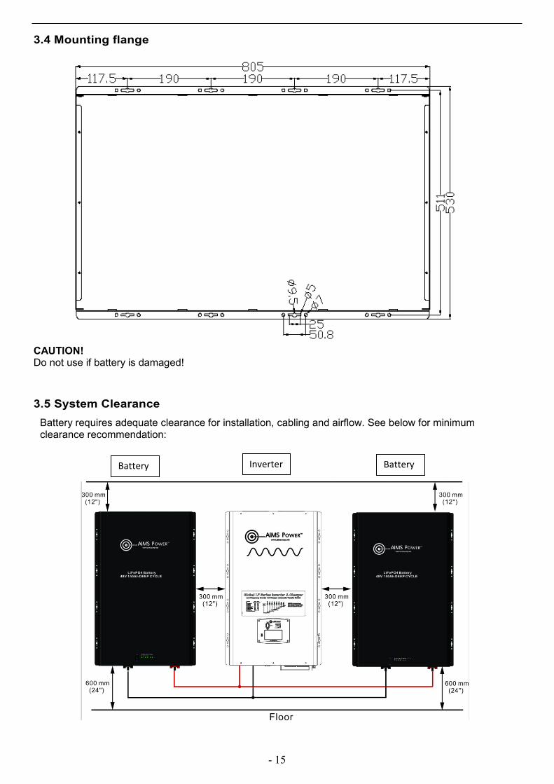
3.5 System Clearance Battery requires adequate clearance for installation, cabling and airflow. See below for minimum clearance recommendation:
Inverter Battery Battery

- 16
3.6 Battery Pack Installation CAUTION! Make sure the DC device is in the off position and any disconnects (if used) are turned off before connecting the power cable to the battery pack.
NOTE! USE PROPER BRACKETS, SUPPORTS, AND/OR STRAPS TO HANDLE THE WEIGHT OF THE BATTERY. WELL VENTILATED, HEAVY DUTY BATTERY CABINET IS RECOMMENDED.
3.7 DC Wiring AIMS Power recommends keeping the battery pack as close as possible to the DC load. Refer to the below chart for minimum wire size. If the length of cable is longer than 4 feet, use the next larger size of cable.
Model DC Output Voltage Wire Gauge
LFP24V300A 25.6Vdc 1/0 AWG
LFP48V150A 51.2Vdc 2 AWG
Performance is improved by using a thicker cable and shorter runs. If unsure, round up and keep the length as short as possible.
For wiring configurations for your specific system, please contact AIMS Power for more information.
WARNING The torque rating range for DC terminal is 19.8NM-24.6NM, and the suggested torque rating is 22.5NM. Over torqueing may cause the bolt to break.
WARNING Max batteries connected in parallel is up to 10 batteries. Only use identical batteries. All cables must be the same length and size.
DO NOT WIRE IN SERIES!

- 17
4 Operation 4.1 Recommended Operating Conditions
Installation location Indoors (wall or flat mounted) Operating temperature @ -4°F to 149°F (-20 to 65°C) Operating temperature (Recommended) 59°F to 86°F (15 to 30°C) Humidity 5% to 95% Altitude Max 6,562ft (2,000m) Cooling Natural Convection
4.2 Powering Battery Pack 1. Turn on power switch after installing the battery pack. For parallel connected batteries, turn on power switch one by one.2. Within seconds, the internal main relay will pick up, all LEDs will light up.3. If the battery pack initializes successfully, the RUN LED indicator on the front should turn green. The SOC LED indicator will show the current capacity.4. Turn on inverter.* If using with multiple chargers, start up sequencing may need to be followed. CAUTION If battery doesn’t turn on and indicates a FAULT or fails to operate, do not use the battery pack and contact AIMS Power.

- 18
4.3 LED Indicators The LED indicators on the front of the battery pack show its operational state as follows:
LED Flashes at point of SOC
4.4 Turning Off the Battery Pack 1. Turn off DC source (inverter). 2. Turn off battery pack. For parallel connected batteries, turn off power switch one by one. 3. Within a few seconds, the internal main relay will cut off, all LEDs off. CAUTION If not using the battery pack for a long period of time or if there is any fault on the pack, turn off the power switch.
RUN LED(green) System working normal
Alarm LED(red) once/3S Flash: system warning once/1S Flash: system protection Lightning: system fault
SOC LEDs (4 green)
Charging: SOC<25%, LED1、LED2、LED3、LED4 flash in turn 25%<SOC<50%, LED1 flashing, LED2、LED3、LED4 flash 50%<SOC<75%,LED1、LED2 flashing , LED3、LED4 flash 75%<SOC<95%,LED1、LED2、LED3 flashing , LED4 flash SOC>95%,LED1、LED2、LED3、LED4 flashing Discharging: SOC>75%, LED1、LED2、LED3 flashing、LED4 flash 50%<SOC<75%, LED1、LED2 flashing、LED3 flash, LED4 off 25%<SOC<50%, LED1 flashing、LED2 flash, LED3、LED4 off 10%<SOC<25%, LED1 flashing ,LED2 flash, LED3 flash, LED4 off

- 19
4.5 Communication
4.5.1 CAN Port for PC Monitoring Connect the CAN communication card from the battery pack to the computer, after installing the AIMS Power LiFePO4 monitor, the information displays on 7 different tabs. 1. Main Info tab: SOC%, voltage, current, cycles, capacity and running status 2. Balance & MOS tab: cell balancing 3. Cells tab: cell voltage 4. Temp tab: internal cell temperature 5. CAN Msg 6. Configuration tab:
Bus Diagnostics - displays voltage, temp and current Data storage
7. All Info tab: summary of all info per battery if more than one battery is being used (max 10 batteries in parallel)

- 20

- 21

- 22

- 23
5 Troubleshooting
Check the indicators on the front of the battery to determine the status of the battery pack. A warning state is triggered when a condition, such as voltage or temperature, is outside battery’s rating. When the battery pack status falls outside of set limits, it enters a warning state. When a warning is reported, turn off the DC source immediately. Use the monitoring software to identify the cause of the warning.
Warning Alarms Battery Over Voltage Battery Under Voltage Battery Over Temperature Battery Under Temperature Battery Discharge Over Current Battery Charge Over Current
The fault state is cleared when the battery pack recovers to normal operation. If battery pack is not working correctly and the issue persists, contact a qualified technician or AIMS Power. If the battery pack or the inverter indicates FAULT or fails to operate, contact AIMS Power immediately.
6 Warranty AIMS PowerTM lithium batteries include a 10 year prorated warranty against manufacturer defects.
Within the warranty coverage period, AIMS PowerTM will either repair or replace, at its sole discretion, the defective product.
Any shipping charges that occur as a result of a warranty return or exchange are NOT covered by the warranty and are the responsibility of the customer.
The warranty does not cover the following:
• Products that AIMS PowerTM determine, in its sole discretion, to be free of any material orworkmanship defects or flaws• Products evidencing excessive wear, misuse or alteration• Products with missing or defaced labels, stickers, or other identifying information• Improper care or storage (e.g. water damage, damp environments, exposure to extreme heat orcold temperatures, unsanitary environment)• Alterations or customizations• Improper use or wiring• Items that were purchased second hand, or from an unauthorized seller• Items outside of the covered warranty period• Normal wear and tear of the product