Embed Size (px)
Citation preview

1
Lithium Air Battery with a Lithiated Al/Carbon Anode
Ziyang Guo, XiaoLi Dong, Yonggang Wang*, Yongyao Xia
Department of Chemistry and Shanghai Key Laboratory of Molecular Catalysis and Innovative Materials, Institute of New Energy, Fudan University, Shanghai 200433, China. * Corresponding author. Tel & Fax: 0086-21-51630318 E-mail address: [email protected]
Electronic Supplementary Material (ESI) for ChemComm.This journal is © The Royal Society of Chemistry 2014

2
Experimental Section
Preparation of Al/carbon composite electrode and O2 catalytic electrode: Carbon
Black (CB) and poly (tetrafluoroethylene) (PTFE) binder was dispersed in
isopropanol to form slurry with a weight ration of 9:1 (CB: PTFE). Next, the slurry
(CB + PTFE) was rolled into a membrane, and then pressed on an Al mesh to form an
Al-carbon composite anode. In the preparation of carbon-based O2 catalytic electrode,
carbon black Super P (80 wt %) and a polyvinylidene fluoride binder (PVDF, 20 wt %)
were intimately mixed in an N-methyl-2-pyrrolidone (NMP) solution, and the
resulting slurry was coated on a carbon paper (TGP-H-060 carbon paper, Torray). The
total mass loading of Super P is around 0.8 mg/cm2. The coated electrode was dried
for 12 h at 100 oC under vacuum to remove residual solvent.
Preparation of Li-O2 (or air) battery with a LixAl/C anode: Lithiated Al/carbon
(LixAl/C) composite electrode was first prepared by electrochemical method.
Typically, an Al/carbon composite electrode was coupled with a metallic Li-foil to
form a half-cell using LiPF6-EC/DMC/EMC electrolyte [i.e. LB303 electrolyte
produced by Zhangjiagang Guotai-huarong New Chemical Materials Co., LTO.
(China) for conventional Li-ion batteries], and then was discharged for 25 hours with
a current 0.4 mA/cm2 to form a LixAl/C composite electrode with a uniform solid
electrolyte interface (SEI) film that arises from the decomposition of
EC/DMC/EMC-based electrolyte. Then, the cell was disassembled in a glove box
filled with Ar to obtain LixAl/C electrode. Next, resulting LixAl/carbon electrode was
coupled with a carbon-based O2 catalytic electrode in a tetra(ethylene) glycol
3
dimethyl ether–LiN(CF3SO2)2 (TEGDME–LiTFSI) electrolyte to form a Li-O2 (or air)
battery with a LixAl/C anode. The “LixAl/C-electrode/ separator containing electrolyte
/ O2-electrode” was sealed into a Swagelok cell with an air hole 0.8 cm2 placed on the
positive electrode side to allow the O2 (or air) to flow in. Li-O2 (air) battery was
assembled with the same method. LAND cycler (Wuhan Land Electronic Co. Ltd.)
was used for electrochemical investigation.
Detection of Li2O2 via XRD: Firstly, a Li-O2 battery with a LixAl/C anode was
discharged at a current density of 100 mA g-1 with a fixed capacity of 1000 mAh g-1.
After that, the cell was disassembled in a glove box filled with Ar to obtain the
discharged electrode. Then, the discharged O2 catalytic electrode was washed with
DMC and was dried under vacuum at room temperature for 3 hours. Next, the
resulting electrode was detected by XRD. The O2 catalytic electrode before discharge
(or after recharge) was detected with the same method.
Characterization: XRD patterns were recorded on Bruker D8 Advance Diffractometer)
using Cu Kα radiation. The morphologies of the sample were characterized with SEM
(FE-SEM S-4800) and TEM (Joel JEM2010).
4
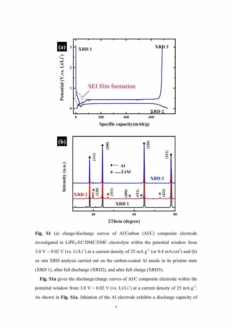
Fig. S1 (a) charge/discharge curves of Al/Carbon (Al/C) composite electrode
investigated in LiPF6-EC/DMC/EMC electrolyte within the potential window from
3.0 V ~ 0.02 V (vs. Li/Li+) at a current density of 25 mA g-1 (or 0.4 mA/cm2) and (b)
ex situ XRD analysis carried out on the carbon-coated Al anode in its pristine state
(XRD 1), after full discharge (XRD2), and after full charge (XRD3).
Fig. S1a gives the discharge/charge curves of Al/C composite electrode within the
potential window from 3.0 V ~ 0.02 V (vs. Li/Li+) at a current density of 25 mA g-1.
As shown in Fig. S1a, lithiation of the Al electrode exhibits a discharge capacity of
5
720 mAh g-1 with a cutoff potential of 0.02 V (vs. Li/Li+). The main lithiation
potential of the Al/carbon composite electrode can be observed at around 0.26 V
which is consistent with previous reports. RS1 The initial plateau between 0.7 V and
0.2 V arises from the reduction of EC/DMC/EMC-based electrolyte on the surface of
carbon layer to form solid electrolyte interface (SEI) film, which has been widely
reported in previous investigations about conventional Li-ion batteries.RS2, 3 On charge
(or de-lithiathion) process, the Al/C composite electrode displays a capacity of 680
mAh g-1 with an average potential of 0.45 V (Fig. 1a). The lithiation/delithiation
mechanism of Al anode can be summarized as equation (1):
(1 )xLi xe Al xLiAl x Al+ −+ + ←⎯→ + − (1)
In theory, the formation of LiAl (x =1) from Al should provide a theoretical capacity
of 993mAh g−1. In order to clarify this operating mechanism, ex situ XRD analysis
(see Fig. S1b) was conducted, in sequence, on the Al/C composite electrode in its
pristine state (XRD1), after full lithiation for formation of LixAl (XRD2) and after
complete recharge for the reconversion of Al (XRD3). RS1 It can be detected in the
XRD2 discharge pattern (Fig. S1b) that formation of a LiAl alloy is apparent from
the presence of characteristic peaks corresponding to the (220), (311), (400), (331),
(422) and (511) planes (JCPDS 03-1215). The aluminium peaks were also present
(JCPDS04-078), but no peaks for Li (JCPDS 15-401), Li3Al2 (JCPDS 26-1008) or
Li9Al4 (JCPDS 24-0008) were detected. These results indicated that Al reacted only
partially, consistent with the fact that the calculated capacity was lower than
theoretical capacity. One can also observe that these characteristic peaks related to
LiAl vanish again in the XRD3 charge pattern. These results well support the
interpretation about the operating mechanism of Al anode, and also quite agree
with Morales et al.’ recent report. RS1 RS1. J. Morales, R. Trocoli, S. Franger, J. Santos-Pena, Electrochim. Acta, 2010, 55,3075. RS2. K. Xu, Chem. Rev., 2004, 104, 4303; S. H. Zhang, M. S. Ding, K. Xu, J. Allen, T. R. Jow, Electrochem. Solid-State Lett., 2001, 4, A206; P. Verma, P. Maire, P. Novak, Electrochim. Acta, 2010, 55, 6332.
6
RS3. H. Buqa, A. Wursig, J. Vetter, M. E. Spahr, F. Krumeich, P. Novak, J. Power Sources, 2006, 153, 385;F. Kong, R. Kostecki, G. Nadeau, X. Song, K. Zaghib, K. Kinoshita, F. Mclarnon, J. Power Sources, 2001, 97, 58.
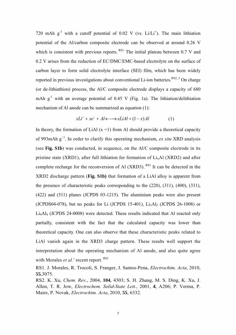
Fig. S2 XRD patterns of O2 catalytic electrode of Li-O2 battery with a LixAl/C anode.
(a)before discharge, (b) after discharge and (c) after recharge.
It can be detected from Fig. S2 that the characteristic peaks related to Li2O2
exist in the XRD pattern after discharge and vanish again in the XRD pattern after
recharge, indicating the reversible conversion between O2 and Li2O2 over
discharge/charge process.
20 40 60
c
b ***
*
*
*
In
tens
ity (a
.u.)
2Theta / degree
Li2O2
a

7
Fig. S3 (a) Pre-lithiation of Al/C electrode in LiFP6-EC/DMC/EMC electrolyte and (b)
Lithiatation/delithiation cycle of LixAl/C electrode in TEGDME-LiCF3SO3
electrolyte at a current of 25mA/g (0.4mA/cm2).
An Al/C electrode was coupled with metallic Li-foil to form a half-cell using
LiPF6-EC/DMC/EMC electrolyte, and then was discharged for 25 hours with a
current 0.4 mA/cm2 to realize pre-lithiation. Then, the cell was disassembled in a
glove box filled with Ar to obtain LixAl/C electrode. Next, the resulting LixAl/C was
coupled with a fresh Li-foil anode to form a half-cell using TEGDME-LiCF3SO3
electrolyte. The performance of the LixA/C electrode in TEGDME-LiCF3SO3
electrolyte was investigated with a fixed charge/discharge time of 10 hours.
As shown in Fig. S3, lithiation/delithiation polarization of LixAl/C anode is about
0.19V in TEGDME-LiCF3SO3 electrolyte.
0 50 100 150
0
2
4(b)
V
olta
ge (V
)
Time (hour)
(a)
Pre-lithiation
in LiFP6-EC/
DMC/EMC Lithiation/delithiation cycle in TEGDME-LiCF3SO3
8
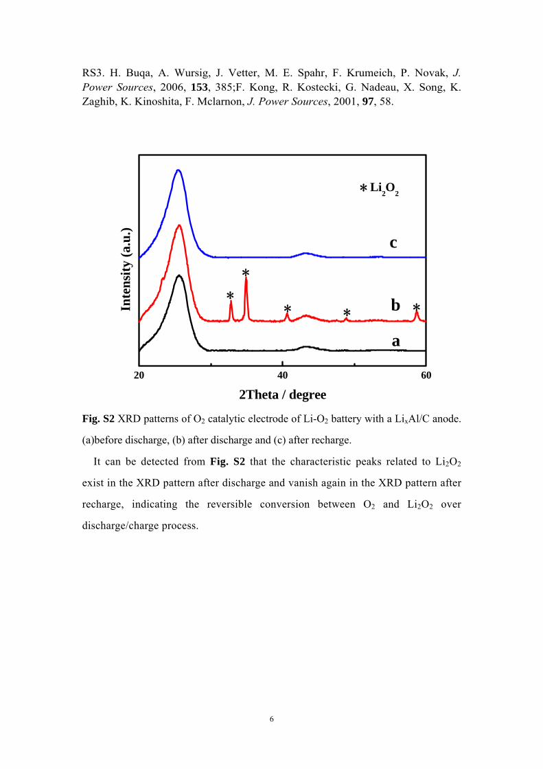
Fig. S4 Discharge/charge voltage profiles of Li-O2 battery with a LixAl/C anode (a)
and Li-O2 battery with a Li-anode (b) investigated at low current density of 50 mA/g.
It can be detected from Fig. S4a that Li-O2 battery with a LixAl/C anode displays
a total polarization (i.e. the voltage gap between discharge and charge) of 1.09V at the
current density of 50mA/g. However, a total polarization between discharge and
charge of 1.48V can be detected in the voltage profiles of Li-O2 battery with a
Li-anode (Fig. S4b).
0 100 200 300 400 5001
2
3
4
5
1.48 V
2.70 V
Vol
tage
(V)
Specific capacity(mAh/g)
4.18 V(b)
0 100 200 300 400 5001
2
3
4
5
1.09 V
2.49 V
Vol
tage
(V)
Specific capacity(mAh/g)
3.58 V(a)

9
Fig. S5 photos of fresh metallic Li (a) and metallic Li that was exposed in ambient air
for several minutes (b). As shown in Fig. S5, only after been exposed in ambient air
for several minutes, the silvery white Li-metal have been converted into brown/black
Li-metal.
Fig. S6 TEM images (a, b) with different magnifications of carbon layer in lithiated
Al/carbon composite electrode. As shown Fig. S6, the carbon material (i.e. carbon
black) is full coated by SEI film.
10
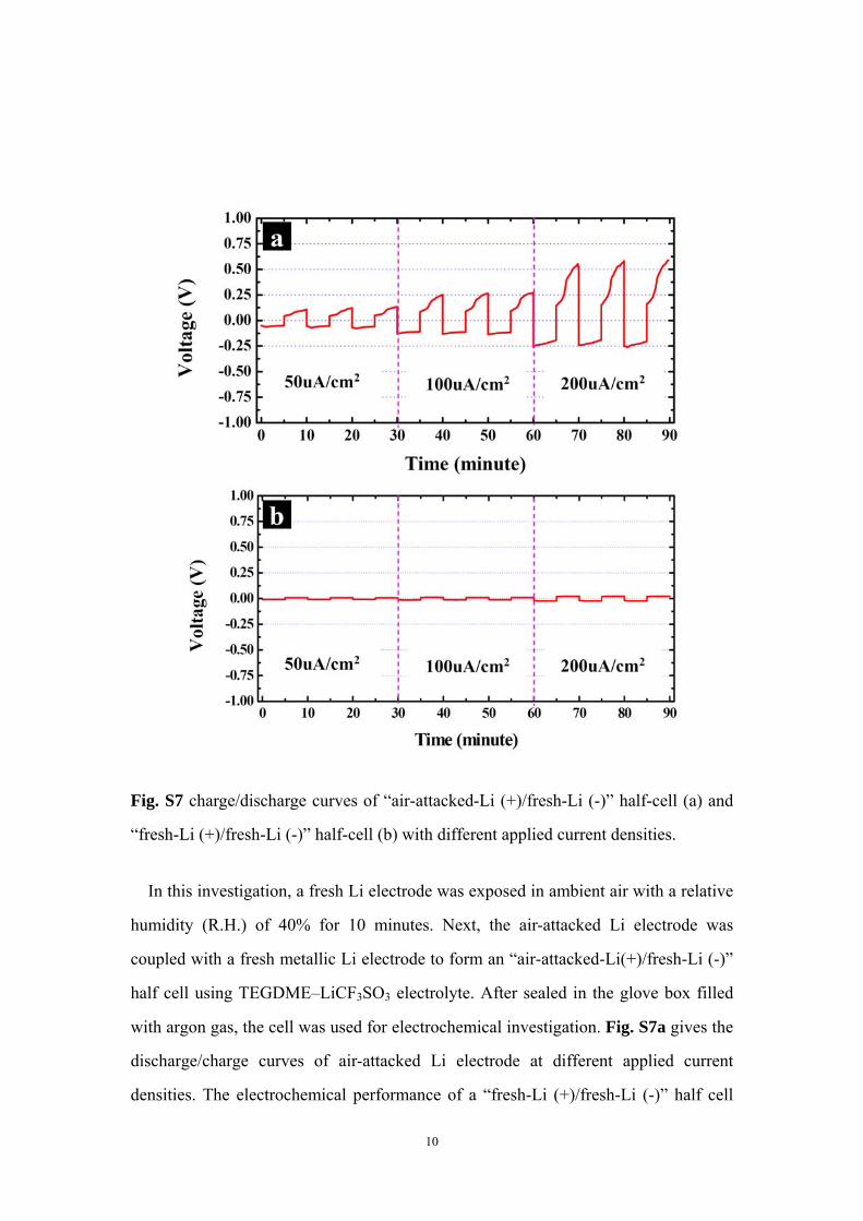
Fig. S7 charge/discharge curves of “air-attacked-Li (+)/fresh-Li (-)” half-cell (a) and
“fresh-Li (+)/fresh-Li (-)” half-cell (b) with different applied current densities.
In this investigation, a fresh Li electrode was exposed in ambient air with a relative
humidity (R.H.) of 40% for 10 minutes. Next, the air-attacked Li electrode was
coupled with a fresh metallic Li electrode to form an “air-attacked-Li(+)/fresh-Li (-)”
half cell using TEGDME–LiCF3SO3 electrolyte. After sealed in the glove box filled
with argon gas, the cell was used for electrochemical investigation. Fig. S7a gives the
discharge/charge curves of air-attacked Li electrode at different applied current
densities. The electrochemical performance of a “fresh-Li (+)/fresh-Li (-)” half cell
11
was also investigated for comparison (Fig. S7b). As shown in Fig. S7a, the
air-attacked Li electrode displays an obvious polarization of about 150 mV between
dissolution/deposition reactions (i.e. charge/discharge reactions) even at the low
current density of 50uA cm-2. When the applied current density is enhanced to 200uA
cm-2, this polarization is even as high as 500 mV (Fig. S7a). However, such obvious
polarization can not be observed in the investigation of fresh-Li electrode at various
current densities (Fig. S7b).
0 1000 2000-0.50
-0.25
0.00
0.25
0.50
0.75
1.00
1.25
1.50
0.235V
Vol
tage
(V)
Time (minute)
0.529V
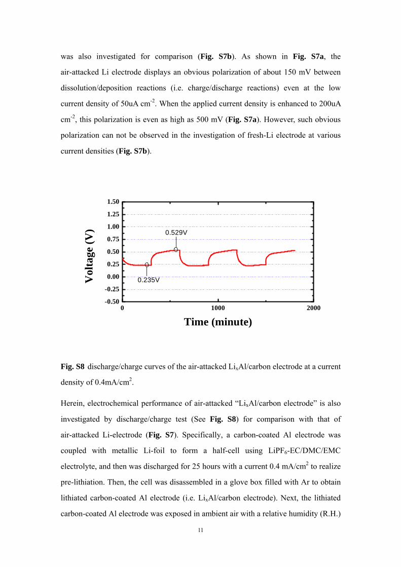
Fig. S8 discharge/charge curves of the air-attacked LixAl/carbon electrode at a current
density of 0.4mA/cm2.
Herein, electrochemical performance of air-attacked “LixAl/carbon electrode” is also
investigated by discharge/charge test (See Fig. S8) for comparison with that of
air-attacked Li-electrode (Fig. S7). Specifically, a carbon-coated Al electrode was
coupled with metallic Li-foil to form a half-cell using LiPF6-EC/DMC/EMC
electrolyte, and then was discharged for 25 hours with a current 0.4 mA/cm2 to realize
pre-lithiation. Then, the cell was disassembled in a glove box filled with Ar to obtain
lithiated carbon-coated Al electrode (i.e. LixAl/carbon electrode). Next, the lithiated
carbon-coated Al electrode was exposed in ambient air with a relative humidity (R.H.)
12
of ~ 40% for 10 minutes, which is as same as the air-attacking condition for metallic
Li-electrode (see explanation for Fig. S7). After that, air-attacked LixAl/carbon
electrode was coupled with a fresh metallic Li electrode to form an “air-attacked
LixAl/carbon (+)/fresh-Li (-)” half cell. After sealed in the glove box filled with argon
gas, the cell was used for electrochemical investigation. As shown in Fig. S8, the
air-attacked LixAl/C electrode displays a polarization of about 0.294V (=
0.529V-0.235 V) which is slightly higher than the polarization of the fresh LixAl/C
electrode (0.19V=0.45-0.26V; see Fig. S3). However, the air-attacked metallic
Li-anode exhibits very high polarization (see Fig. S7). Therefore, it can be assumed
that the carbon layer with a uniform SEI film plays the role of buffer layer that can
alleviate the air-attacking on LixAl anode. In addition, the hydrophobic character of
carbon black and polytetrafluoroethylene also potentially reduces the H2O-attacking.