Embed Size (px)
Citation preview

This content has been downloaded from IOPscience. Please scroll down to see the full text.
Download details:
IP Address: 129.247.247.238
This content was downloaded on 08/08/2017 at 11:14
Please note that terms and conditions apply.
Liquid metals for solar power systems
View the table of contents for this issue, or go to the journal homepage for more
2017 IOP Conf. Ser.: Mater. Sci. Eng. 228 012012
(http://iopscience.iop.org/1757-899X/228/1/012012)
Home Search Collections Journals About Contact us My IOPscience
You may also be interested in:
Local symmetry in liquid metals probed by x-ray absorption spectroscopy
Fabio Iesari and Andrea Di Cicco
Optimization of PV/WIND/DIESEL Hybrid Power System in HOMER for Rural Electrification
Q Hassan, M Jaszczur and J Abdulateef
Calibration of high-heat-flux sensors
J Ballestrín, M Rodríguez-Alonso, J Rodríguez et al.
An economic evaluation comparison of solar water pumping system with engine pumping system for rice
cultivation
Kasem Treephak, Jutturit Thongpron, Dhirasak Somsak et al.
The properties of liquid metals Broofchaven, September 1966
J E Enderby
Adaptive robust control of chaotic oscillations in power system with excitation limits
Wei Du-Qu and Luo Xiao-Shu
Research on Stability of the Power System
Dong Xie, Dajin Zang and Peng Gao
Casimir force between liquid metals
R. Esquivel-Sirvent and J. V. Escobar
WAMS measurements pre-processing for detecting low-frequency oscillations in power systems
P Y Kovalenko

1
Content from this work may be used under the terms of the Creative Commons Attribution 3.0 licence. Any further distributionof this work must maintain attribution to the author(s) and the title of the work, journal citation and DOI.
Published under licence by IOP Publishing Ltd
1234567890
LIMTECH IOP Publishing
IOP Conf. Series: Materials Science and Engineering 228 (2017) 012012 doi:10.1088/1757-899X/228/1/012012
Liquid metals for solar power systems
J Flesch1, K Niedermeier
1, A Fritsch
2, D Musaeva
3, L Marocco
1,4, R Uhlig
2,
E Baake3, R Buck
2 and T Wetzel
1
1 Karlsruhe Institute of Technology (KIT), Institute for Nuclear and Energy
Technologies, Hermann-von-Helmholz Platz 1, 76344 Eggenstein-Leopoldshafen,
Germany 2 German Aerospace Center (DLR), Institute for Solar Research, Pfaffenwaldring 38-
40, 70569 Stuttgart, Germany 3 Leibniz Universität Hannover (LUH), Institute of Electrotechnology, Wilhelm-
Busch-Str. 4, 30167 Hannover, Germany 4 Politecnico di Milano, Department of Energy, via Lambruschini 4, 20156 Milan,
Italy
E-mail: [email protected]
Abstract. The use of liquid metals in solar power systems is not new. The receiver tests with
liquid sodium in the 1980s at the Plataforma Solar de Almería (PSA) already proved the
feasibility of liquid metals as heat transfer fluid. Despite the high efficiency achieved with that
receiver, further investigation of liquid metals in solar power systems was stopped due to a
sodium spray fire. Recently, the topic has become interesting again and the gained experience
during the last 30 years of liquid metals handling is applied to the concentrated solar power
community. In this paper, recent activities of the Helmholtz Alliance LIMTECH concerning
liquid metals for solar power systems are presented. In addition to the components and system
simulations also the experimental setup and results are included.
1. Liquid metals as heat transfer fluids in solar thermal electricity (STE) generation
Concentrating solar thermal power plants are capable of electricity generation that is dispatchable and
renewable. The future competitiveness of this technology depends on the reduction of the cost of
electricity generation.
State-of-the-art solar thermal power plants use thermal oils, water/steam, air or molten salts as heat
transfer fluids (HTF). Those fluids should ideally be chemically stable at high temperatures, have a
high boiling temperature, a low melting point, low cost, enable safe operation and have good corrosion
properties.
Although water and air are highly available and cheap fluids, they are not suitable for directly
storing thermal energy at high temperatures. Oils can typically not operate at temperatures that would
allow for high efficiency in the thermal-to-electric power conversion process. Molten ‘solar salt’ (mass
specific composition: 60 % NaNO3 and 40 % KNO3) is cheap and can be used as direct storage
medium due to its high heat capacity. For these reasons, it is the state-of-the art HTF for STE plants
with thermal storage. Solar salt melts at 220 °C. Under strong solar irradiation, it can be operated up to

2
1234567890
LIMTECH IOP Publishing
IOP Conf. Series: Materials Science and Engineering 228 (2017) 012012 doi:10.1088/1757-899X/228/1/012012
an outlet bulk temperature of 565 °C, but not higher in order to avoid film temperatures above 600 °C
where it chemically decomposes.
Advanced heat transfer fluids should have a low melting and a high boiling temperature resulting
then in an increased operating temperature range. This reduces expensive auxiliary heating of the
piping in non-irradiated sections and enables higher outlet temperatures for advanced power
conversion cycles. These may lead to reduced costs in electricity generation ([1], [2]).
Pure liquid metals and their alloys have high thermal conductivities and thus show high potential
for large heat transfer rates.
Pacio and Wetzel [3] performed a screening of liquid metal candidates as heat transfer fluids in
STE systems. Based on a review study of liquid metals in solar power systems, they found that the
candidates with the highest potential are sodium, lead-bismuth eutectic alloy (LBE) and tin. For
example, Kesselring et al. [4] published on practical experiences with a sodium cooled receiver and
Falcone [5] on thermal energy storage with sodium. More recent publications by Singer et al. [6] and
Boerema et al. [7] on sodium and Kotzé et al. [8] on sodium-potassium assessed the thermodynamic
possibilities of liquid metals in STE systems, however lacked the state-of-the-art of the technology
associated.
Sodium and LBE have vast operational experience and engineering handbooks exist ([9] and [10]).
They have a lower melting point than salt and a higher upper temperature limit: sodium boils at 883°C
and LBE at 1670°C. Sodium, however, violently reacts with water and therefore requires special
safety considerations in loop operation and LBE shows significant corrosion with structural steels
unless the dissolved oxygen content is controlled. Due to their low heat capacities compared to salt,
direct thermal storage will not be economically feasible in two-tank systems and special storage design
is required. Possible indirect storage options using sodium are discussed in section 2.2 of this paper.
Pacio and Singer [11] assessed and summarized the thermo-hydraulic properties of sodium and
LBE compared to solar salt with special attention to the thermal efficiency of the receiver and the
conversion cycle. By using fluids capable of achieving high heat transfer rates in an economically
feasible way the concentration of the incident light can be increased. A reduced receiver aperture
could then generate the same power output at reduced losses, being radiation and convection losses
proportional to the surface area of the receiver. They found a possible increase of receiver efficiency
and outlet temperature in liquid metal cooled receivers. They showed a 20 % higher thermal efficiency
for flux densities of 2 MW/m² and fluid outlet temperatures of 900 °C for liquid metal-cooled
receivers and conversion cycles compared to molten salt reference case. Such high flux density may be
possible due to the potential of obtaining very large convective heat transfer coefficients with liquid
metals, especially with sodium.
The thermo-hydraulic analysis of the potential of receiver operation at higher temperature and
increased cooling rate was therefore promising.
Pacio et al. [12] proposed basic concepts for solar plants with liquid metal temperatures of up to
700 °C that should, from a thermodynamic point of view, show high advantages over molten salt.
Singer et al. [13] assessed the cost reduction potential for a plant with a supercritical steam cycle,
which could be combined with a solar power plant if the HTF outlet temperature is 635 °C, a too high
value to be reached with solar salt. They found no economic advantage from the increased temperature
and steam pressure when salt (the development of which is an open task as of today) was used, due to
the additional costs for the power block.
While at that state positive thermo-hydraulic perspectives existed, uncertainty remained with regard
to the costs of a system operated with liquid metals as heat transfer fluid. Also the technological
readiness was unclear. Therefore, the different groups in LIMTECH Project B2 have addressed these
issues both numerically and experimentally. The different aspects are described in the following
sections.
2. Simulations
In order to assess liquid metals as possible HTF for STE plants, numerical simulations have been
performed to analyze the heat transfer under asymmetrical heating (section 2.1) and to determine the
best thermal storage configuration when using sodium as HTF (section 2.2). Furthermore, a detailed

3
1234567890
LIMTECH IOP Publishing
IOP Conf. Series: Materials Science and Engineering 228 (2017) 012012 doi:10.1088/1757-899X/228/1/012012
techno-economic study has been conducted to obtain a fair cost comparison between solar salt, LBE
and sodium in a real plant condition (section 2.3) and finally, the potential for an electromagnetic
pump for the liquid metal circulation has been evaluated (section 2.4).
2.1 Heat transfer in a non-uniformly heated single tube
The central receiver is typically arranged as a series of parallel tubes in which the cooling medium
flows and that are irradiated by the concentrated sunlight on their outer surface. The latter condition
results in a circumferentially and longitudinally non-uniform heat flux, resulting in high thermal
stresses in the tube walls. Therefore, for properly designing the receiver, knowledge of the maximum
wall temperature values is required. For this purpose, the convective heat transfer coefficient should be
determined. Several Nusselt number correlations are available in literature, also for liquid metals, but
all of them are valid in principle for a uniform heat flux on the tube’s wall. This creates doubts about
the applicability of them to the present configuration, where the tube is irradiated from only one side.
Therefore, computational fluid dynamics has been used to analyze the conjugate heat transfer in the
receiver tube of a solar thermal tower operated with a liquid metal. A representative longitudinally and
circumferentially varying heat flux, shown in Error! Reference source not found. has been applied
on only half of the tube´s surface. Appropriate values for engineering applications of the solid-to-fluid
thermal conductivity, wall thickness ratio, Péclet number and diameter-to-length ratio have been
considered.
Figure 1. Non-dimensional
heat flux distribution on the
outer tube’s wall.
Reproduced from [14] with
permission. Copyright © 2016
Elsevier Masson SAS. All
rights reserved.
Due to the very low Prandtl number, the heat transfer mechanism of liquid metals differs from that
of medium-to-high Prandtl number fluids like air, water or oils. As a consequence, the Reynolds
analogy, which results in a constant and almost unitary turbulent Prandtl number, does not apply to
liquid metals. In the simulations, the Boussinesq assumption is used for the turbulent heat fluxes,
which then result proportional to the mean temperature gradient through the turbulent thermal
diffusivity. This is calculated as the ratio of the turbulent viscosity to the turbulent Prandtl number.
While the first derives from the solution of an equation for the turbulent kinetic energy and one for its
dissipation rate, two different approaches have been used to evaluate the turbulent Prandtl number. On
the one hand using a locally varying correlation and on the other hand by solving two additional
transport equations, namely one for the temperature variance and one for its dissipation rate. This last
approach is computationally more expensive and can give rise to stability issues but it also allows to
consider the dissimilarities between the thermal and dynamical turbulence fields. For a thorough
description of the equation solved, the models used and the numerical setup the interested reader is
referred to Ref. [14] and references therein.
Detailed results of the inner, outer, fluid bulk temperature, turbulent Prandtl number and Nusselt
number are also reported in Ref. [14]. In what follows only some results, particularly relevant for the
receiver design, are discussed.
The circumferentially averaged Nusselt numbers do not vary significantly by using either a proper
correlation or two additional transport equations to evaluate the turbulent Prandtl number. This

4
1234567890
LIMTECH IOP Publishing
IOP Conf. Series: Materials Science and Engineering 228 (2017) 012012 doi:10.1088/1757-899X/228/1/012012
suggests that, at least for this type of attached boundary layer-like flow, the former simpler approach
can be used for the simulations.
When comparing the circumferentially averaged Nusselt numbers along the tube axis with those
obtained with a correlation developed for a uniformly applied heat flux, marked discrepancies are
evident, highlighting the inadequacy of the available correlations for this type of configuration.
The same big differences do not appear when comparing for different Péclet numbers the
circumferentially and longitudinally averaged Nusselt numbers with those obtained with a correlation
for uniform heat flux over the tube’s perimeter. Indeed, in this case and for the Péclet numbers here
considered, the computed Nusselt values are within ±10 % of the correlation. The reason for this is the
averaging procedure along the longitudinal direction that contributes in canceling out the local
differences. It should be remarked that for both cases the error between simulation and correlation
increases with increasing Péclet number.
Two recommendations, useful when numerically simulating a solar receiver tube with liquid metal
flowing inside, can be derived from this analysis:
A correlation depending on the local turbulent viscosity, 𝜈𝑡, can be used for evaluating the
turbulent Prandtl number, 𝑃𝑟𝑡:
𝑃𝑟𝑡 = 0.85 +0.7
𝑃𝑟 ∙ 𝜈𝑡𝜈
(1)
When performing simplified one-dimensional simulations, it is important to use a circumferentially
averaged but axially varying Nusselt number derived from a detailed CFD simulation, in order to
obtain reliable wall temperatures, which are crucial for the design of the receiver.
2.2 Thermal energy storage for a STE plant with sodium as HTF
The STE technology has the advantage of being able to store thermal energy for later use directly,
efficiently and cost-effectively. Currently, the levelized cost of electricity (LCOE) of a solar thermal
power plant with a 9 hour storage is 40 % lower than the corresponding photovoltaic plant including a
battery [15].
Operational solar power plants like Crescent Dunes [16] and Gemasolar [17] use a two-tank
configuration including a “cold” tank to store the molten salt before heating it up in the thermal
receiver and a “hot” tank for the hot liquid leaving the receiver.
This configuration has also been used in the IEA-SSPS sodium facility in Almeria in the 1980s
with a storage capacity of 5 MWhth using 60 tons of sodium to provide the power block with 1 MWth
for 5 hours [18]. Furthermore, Pomeroy [19] suggested a packed bed storage with iron spheres and
indirect storage with molten salt as alternatives to a direct two-tank configuration. To the authors’ best
knowledge, no further studies relating to thermal energy storage for a liquid metal solar power plant
have been carried out since.
Therefore, a thorough evaluation of the potential storage options for a STE plant with sodium as
HTF were performed. Suitable thermal energy storage systems were selected by applying the
following five criteria on thermal energy storage systems available in the literature: storage medium
cost, storage density, cycling behavior, maturity level and suitability for sodium. Three different kinds
of thermal energy storage types were considered: sensible (direct and indirect), latent and
thermochemical. This assessment showed that one promising storage system for sodium is a direct
thermocline system with filler material, mainly due to low cost and relatively high storage density.
By including a filler material in the storage tank (porosity 𝜀 = 0.25), the storage medium costs can
be reduced to less than one third (from 27.2 €/kWhth to 7.5 €/kWhth) and the volumetric storage
density can be more than doubled compared to a sodium-only system (from 277.8 MJ/m3 to 725.6
MJ/m3). Physical properties and cost data of the materials for this calculation can be found in Ref.
[20].
For a comparison with molten salt and a detailed evaluation of all the considered storage options
the interested reader is also referred to Ref. [20].
The selected thermocline storage system with filler material is explained in the following. A
principle scheme of an STE plant including the storage system is shown in Figure 2. The hot and the
cold fluid are separated by a thermocline layer due to different densities of the hot and the cold fluid.

5
1234567890
LIMTECH IOP Publishing
IOP Conf. Series: Materials Science and Engineering 228 (2017) 012012 doi:10.1088/1757-899X/228/1/012012
If thermal energy is in excess, hot fluid enters from the top, “pushes” the thermocline towards the
bottom and cold fluid exits the storage tank (charging). However, if thermal energy is needed, e.g.
after sunset, cold fluid enters from the bottom, pushes the thermocline towards the top and hot fluid
exits at the top of the tank (discharging). A part of the fluid is replaced by solid filler material.
Therefore, during charging, heat is transferred to the filler material and, during discharging, the heat is
returned from the hot filler material to the cold fluid.
Figure 2. Principle scheme of a liquid metal-based solar tower
plant with a single-tank storage system.
Single-tank thermal energy storage systems with filler material have been investigated
experimentally and theoretically before. Experimental studies on thermocline storage systems with
filler material have firstly been performed in the STE plant Solar One in the 1980s with a storage
capacity of 170 MWhth [21]. The storage tank filled with rocks and sand with thermal oil as HTF
proved the potential of single-tank storage systems. Pacheco et al. [22] published results of a pilot-
scale experiment of 2.3 MWhth in Sandia Laboratories with molten salt as HTF and a quartzite rock
and sand mixture as filler. Recently, lab-scale experiments with molten salts, oil or air as HTF have
been performed to re-demonstrate the feasibility of a thermocline storage system and to obtain new
data for validation purposes ([23], [24]). Furthermore, the German Aerospace Centre (DLR) is
currently building a pilot-scale facility for material testing and demonstration purposes [25].
To the authors’ best knowledge, neither an experimental nor a systematic theoretical study have
been conducted for liquid metals in a thermocline storage system with filler material yet. Therefore, a
two-dimensional two-phase model will be developed to test the feasibility of liquid metal in a
thermocline system with filler material.
2.3 Commercial plant configuration and LCOE analysis
The receiver tests with liquid sodium in the 1980s at the Plataforma Solar de Almería (PSA) already
proved the feasibility of liquid metals as HTF in STE systems. The conducted tests showed high
receiver efficiency over 90 % [26]. Operation at high flux and power levels even resulted in higher
efficiencies. From a thermodynamic point of view, the use of liquid metals is therefore beneficial. But
in practical applications like power plants the electricity production costs are more important than the
efficiency. This section contains a techno-economic analysis of such a power plant which allows a
precise assessment of the liquid metal technology. The first step in such an analysis is to identify
promising configurations. A concept study with STE systems using liquid metals as HTF and/or
storage material was carried out [27] with innovative systems including component / material
selections and temperature ranges.
Solar salt was the choice of HTF in the Solar Two plant (1995) [28], in Gemasolar (2011) [17], in
Crescent Dunes (2015) [16] and is the choice for most of the announced big solar thermal projects: e.
g. Atacama-1, Chile with Pel = 110 MW; Redstone, South Africa with Pel = 100 MW; Copiapo, Chile

6
1234567890
LIMTECH IOP Publishing
IOP Conf. Series: Materials Science and Engineering 228 (2017) 012012 doi:10.1088/1757-899X/228/1/012012
with Pel = 260 MW; Supcon, China with Pel = 50 MW [16]. Therefore, the reference system in this
study is based on such a molten salt system (see Figure 3 left). All liquid metal concepts are designed
and calculated with the same tools and compared to this reference system. In all cases, external
receivers with 360°-field are used. The reference case for the comparison is a large scale power plant
(Pel = 125 MW) at the location Postmasburg, South Africa.
Figure 3. Left: Flow schematic of a molten salt central receiver system, right: Flow schematic of a
liquid metal/molten salt binary central receiver system [5].
The salt temperature in the loop ranges between 290 – 565 °C. The software HFLCAL [29] is used
for the field layout and the tower height.
As discussed in section 1, liquid metals inherit the possibility to increase the upper temperature
limit for higher system efficiencies. In this case, a high temperature storage would be necessary, which
is up to now not available or too expensive [27]. Additionally, the comparability between two
concepts decreases the more different they are. For this reason all systems analyzed in this paper have
the same power block and the same thermal storage system. The only differences are the receiver
system with the HTF and the associated heliostat field (see Figure 3 right). The presented results are
therefore the lower limit of the potential benefit of liquid metals. Higher system temperatures and
innovative storage concepts (see section 2.2) can further fulfil the potential of liquid metals.
The presented work consists of a comparison between two different liquid metal systems (one with
sodium and the other with LBE) and a reference system with solar salt as HTF.
A major part of the parasitic losses in the solar salt system (see Figure 3 left) is due to the high
pressure head of the pump which works in an open loop, because the 2-tank storage is at atmospheric
pressure. Typically, the salt is pumped up the tower and then throttled at the tower base before it enters
the hot storage tank. The liquid metal receiver and the intermediate heat exchanger could be designed
as a close loop system in which the work required to circulate the liquid metal must only overcome the
friction losses of the piping. In this case, however, the intermediate heat exchanger has to be placed at
the ground and riser and downcomer are filled with the liquid metal. If sodium is used as HTF, the
static pressure at the ground would be approximately half of that with solar salt. For LBE, however,
the static pressure at the ground would be over five times higher (approx. 1 bar/m). For commercial
plants, such a high static pressure would require very thick tubes for riser and downcomer. For this
reason, the intermediate heat exchanger in the LBE system is located just below the receiver, followed
by an open salt loop. Only the sodium system is designed as a close loop, resulting in lower pumping
losses. Additionally, only EM pumps (see section 2.4) are considered for sodium, while mechanical
pumps are foreseen for solar salt and LBE.
All receiver designs presented in this paper are calculated and optimized with the ASTRID code
[30], which was developed within the project B2 of the LIMTECH alliance. An external interface to a
ray tracing software calculates the heat flux distribution on the absorber tubes. The detailed FEM
model also considers radiation exchange between surfaces and forced convection due to influence of
wind. Reducing the absorber area results in higher receiver efficiency and lower receiver cost. But at
the same time, this leads to higher spillage losses and therefore to a lower optical efficiency of the
heliostat field, which increases the required number of heliostats and therefore the cost. In order to
find the optimal trade-off between receiver size and optical efficiency a detailed analysis of field
layout, ray tracing and receiver arrangement based on annual system performance is necessary. The
solar salt receiver results in a mean heat flux density of 0.51 MW/m² with aiming strategy to reduce

7
1234567890
LIMTECH IOP Publishing
IOP Conf. Series: Materials Science and Engineering 228 (2017) 012012 doi:10.1088/1757-899X/228/1/012012
the peak flux to approx. 1.0 MW/m². For liquid metal receivers no aim point strategy is necessary,
resulting in a mean heat flux density of 1.06 MW/m² and a peak value of 2.9 MW/m².
All components are optimized in terms of cost and efficiency to improve the complete system. The
calculated efficiency characteristic of the optimized system including heliostat field, receiver, storage
and power block together with the hourly direct normal irradiance (DNI) and weather data is used to
predict the annual energy yield of the plant and finally calculate the LCOE.
Both the sodium and the LBE system show lower LCOE. Compared to the reference system with
solar salt, the LBE system turns out in 6 % and the sodium system in up to 16 % lower LCOE. The
LCOE reduction is composed by two parts: Firstly, the higher annual efficiency of the liquid metal
systems and on the other hand the lower investment cost. Figure 4 shows on the left the annual energy
turnover for all systems. The overall system efficiency (net electricity divided by the solar input) is
about 2 %-points higher for the liquid metal systems. The second part of the LCOE reduction with
liquid metal systems is due to the lower investment cost (see Figure 4 on the right). The higher system
efficiency of the liquid metal systems leads to slightly smaller and cheaper heliostat fields. However,
the main contribution to the lower LCOE is due to the size reduction of the high flux liquid metal
receiver, which results in significantly lower receiver cost.
Figure 4. Comparison between the reference system with solar salt, the sodium system and the LBE
system, left: annual energy turnover, right: investment cost of main components.
2.4 Electromagnetic pumps for solar power plants
The results of the previously made analysis have shown an advantage of liquid metals used as a heat
transfer fluid. Nervertheless, considering the height of the tower of a concentrated solar power system,
the question of circulating with high-density fluids such as LBE as a liquid metal has arisen. An
expedient way to operate the liquid metal flow and provide a required pressure head in the system is
the use of an electromagnetic (EM) field ([31], [32], [33]). An inductive EM pump was chosen as an
option to fulfill these requirements in an STE plant operating with sodium designed within the
LIMTECH B2 Project. Following advantages of induction pumping were taken into account: 1) high
efficiency at high flow rates (2 - 8 % for heavy metals, 10 – 40 % for alkali metals); 2) absence of
moving parts; 3) ability to work at high temperatures ([34], [35]).
A numerical model of an annular linear induction pump (ALIP) for sodium was derived at Leibniz
University of Hannover (LUH) to examine its abilities to operate with planned solar plant’s

8
1234567890
LIMTECH IOP Publishing
IOP Conf. Series: Materials Science and Engineering 228 (2017) 012012 doi:10.1088/1757-899X/228/1/012012
parameters. A numerical model of an ALIP was built in order to investigate the abilities of a travelling
magnetic field (TMF) (operating frequency is from 5 to 40 Hz) for sodium transporting.
Within the project, a design of an STE plant was developed [27]. The hydraulic parameters of the
solar plant coolant loop, which should have to be provided by the EM pump, are presented in the
Table 1.
Table 1. Pumping requirements for two STE plants with
different capacity and the properties of heat transfer medium.
Parameter Value
Thermal power receiver (MW) 700
Heat transfer fluid Sodium
Operating temperature (°C) 290
Electrical conductivity (S/m) 1,3·10-7
Dynamic viscosity (Pa·s) 2,5·10-4
Density (kg/m3) 840
Mass flow (t/h) 120
Volume flow (m3/h) 8500
There are two most usual types of induction pumps – Flat Linear Induction Pump (FLIP) and
Annular Linear Induction Pump (ALIP). In FLIP the windings are placed on either side of the channel,
or in one side for one sided FLIP. A disadvantage of such a geometry is a high side-effect loss, which
appears due to the current distribution along the width of the channel. In ALIP windings surround the
annular pipe with a ferromagnetic core in the center of the annulus. Induced currents flow in circular
paths thus neglecting side effect loss. The annular geometry of the pipe also permits the use of higher
hydraulic pressure, thus the annular type of the pump was chosen for the simulation [36].
Table 2. Values of the basic parameters of the studied ALIP (Figure 5).
Parameter Value
Operating frequency of TMF, (Hz) 5 – 40
Voltage (V) 1400
Current (A) 1000
Number of windings (for each pole) 9
Distance between the coil and the duct (mm) 3
Inner diameter of the outer pipe (mm) 1000
Outer pipe wall thickness (mm) 75
Duct end length (mm) 200
Duct wall thickness (mm) 10
Winding height (mm) 220
Winding thickness (mm) 27
The developed model of ALIP is presented in Figure 5. A 2D symmetric formulation was used to
obtain electromagnetic and hydrodynamic solutions. The pump consisted of the windings (1), which

9
1234567890
LIMTECH IOP Publishing
IOP Conf. Series: Materials Science and Engineering 228 (2017) 012012 doi:10.1088/1757-899X/228/1/012012
generated magnetic field B (2), and were connected in poly-phase for creation a travelling magnetic
field. The angle between the phases was 60°. The windings were positioned on both sides of the duct
(3). A half of the pipe (4), where the direction of the fluid flow is opposite to the melt in the pump,
was simulated to consider its possible influence on the pumps efficiency. Table 2 provides information
about the dimensions of the pump’s components and applied EM parameters.
In the pump currents within the liquid metal are induced by means of alternating magnetic field B.
Figure 5. The numerical model of ALIP used in simulation of EM
process. Here (1) – windings (poles), (2) – resulting magnetic field, (3)
– duct, (4) – half of the pipe with the flow in opposing pumping
direction.
The numerical simulation cycle included harmonic EM analysis and hydrodynamic solution and
was performed with the ANSYS software packages (Mechanical APDL and Fluent, respectively).
The EM analysis provides the driving forces that are used as source terms in the hydrodynamic
simulation of the flow field. For the latter, the k-𝜔 SST turbulence model is used. The obtained fluid
velocity field is then used again in the EM model to update the source terms. This iterative process
ends when the pressure on the duct inlet and outlet stabilizes.
As shown in Figure 6, although the efficiency of the pump decreases with increased volume flow,
the pressure head is still high enough to provide a required circulation even for large STE plants
(pressure of 1 bar for 700 MW).
The numerical simulation has shown that ALIP is suitable for the needs of concentrating solar
power plant, due to the wide range of developing mass flow (from 5 to 250 t/h) with high enough
pressure head (from 4 to 16 m), ability to work at high temperatures (at 290 °C for sodium) and
efficient operation (71 %).
3. Experiments – The SOMMER test facility
At KIT’s liquid metal laboratory KALLA a small demonstrating system is designed, constructed and
will be operated. The demonstration system incorporates a thermal receiver, a pump for liquid metal
circulation in a closed liquid metal loop, a heater, a cooler, auxiliary heating systems, measurement
1
2
34

10
1234567890
LIMTECH IOP Publishing
IOP Conf. Series: Materials Science and Engineering 228 (2017) 012012 doi:10.1088/1757-899X/228/1/012012
and control. The equipment is sized to make the later addition of a thermal storage system possible.
The cooler is used as a general heat sink. Except for the heater, which enhances the limited solar
power input into the system, the components are representative for a solar power plant.
Figure 6. Maximal pressure head (H), which can be provided by the designed
ALIP dependent on the mass flow (Q). The vertical line marks the mass flow
required in the loop of the solar plant.
3.1 Selection of LBE as the heat transfer fluid for the demonstration loop
Among tin, LBE and sodium, the best suited liquid metal for use in a demonstration loop had to be
selected. Tin was eliminated due to its very corrosive interaction with high-nickel alloys, as concluded
in Ref. [3], and sodium was eliminated due to the effort for operational safety, such as the welding of
tube connections instead of flanging. This effort may be legitimate in a commercial facility. For an
experimental facility, however, where the system may frequently be adjusted and improved this effort
was estimated to be inacceptable. LBE inherently provides the benefit of a lower operational risk and
has been tested in the past as coolant of rod bundles in nuclear power plants.
Even though there are past working experiences of STE plants using sodium as HTF, to the authors'
best knowledge LBE has only been considered as thermal storage fluid, as discussed by Kim et al.
[37]. Therefore, the planned experiments will be helpful to evaluate the possibility to use also LBE as
HTF in a solar plant.
3.2 Goals of the demonstration loop
The following goals are aimed for during the operation of the LBE-loop:
The temperature at the outlet of the thermal receiver at full load shall be above 600 °C
The receiver shall be operated at a solar flux of 1 MW/m2 in average and a peak flux higher
than that by a factor of two to three
The operation shall be demonstrated at fluctuating supply of solar power
The high outlet temperature is intended to demonstrate the capability of liquid metals to achieve
operating temperatures higher than the state-of-the-art molten salt. A high solar flux illustrates the
high cooling capability of liquid metals and the fact that high liquid metal temperatures are not a threat
to the fluid as is the case with molten salt. A fluctuating power supply makes active flow control a
requirement for in-field operation. The thermal power rating for the receiver shall be 10 kW.
4
6
8
10
12
14
16
18
0 50 100 150 200 250 300
H, m
Q, t/h
700 MW
11
1234567890
LIMTECH IOP Publishing
IOP Conf. Series: Materials Science and Engineering 228 (2017) 012012 doi:10.1088/1757-899X/228/1/012012
3.3 Thermal energy storage
The thermal energy storage options are investigated at KALLA separately from the demonstration
loop for the thermal receiver (see section 2.2).
3.4 The light source
As light source for the receiver the sun is used for the SOMMER (Solar furnace with a Molten MEtal-
cooled Receiver) project. The receiver is located in the focal point of a solar furnace. That is an
arrangement of two mirrors, one of which is flat and has the capability of tracking the sun (heliostat),
constantly reflecting the sun rays onto a second, parabolic mirror. The latter mirror concentrates the
light in a focal point. The heliostat mirror in the SOMMER facility has an aperture area of 32 m² and
the parabolic mirror of 16 m². The DNI is measured by a Hukseflux DR-02 Pyrheliometer mounted on
an EKO STR-21G Sun Tracker. Both are installed approximately 10 meters away from to the heliostat
mirror’s center of rotation. At the facility’s location in Eggenstein-Leopoldshafen peak DNI values of
up to 950 W/m² have been measured.
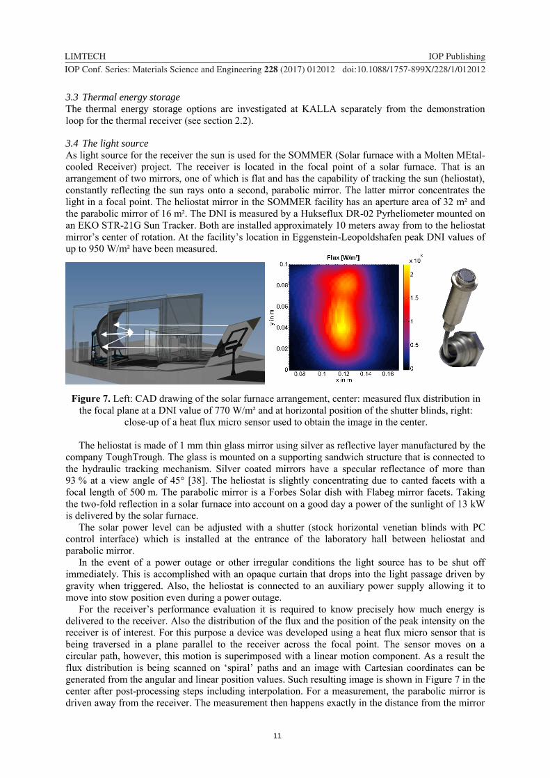
Figure 7. Left: CAD drawing of the solar furnace arrangement, center: measured flux distribution in
the focal plane at a DNI value of 770 W/m² and at horizontal position of the shutter blinds, right:
close-up of a heat flux micro sensor used to obtain the image in the center.
The heliostat is made of 1 mm thin glass mirror using silver as reflective layer manufactured by the
company ToughTrough. The glass is mounted on a supporting sandwich structure that is connected to
the hydraulic tracking mechanism. Silver coated mirrors have a specular reflectance of more than
93 % at a view angle of 45° [38]. The heliostat is slightly concentrating due to canted facets with a
focal length of 500 m. The parabolic mirror is a Forbes Solar dish with Flabeg mirror facets. Taking
the two-fold reflection in a solar furnace into account on a good day a power of the sunlight of 13 kW
is delivered by the solar furnace.
The solar power level can be adjusted with a shutter (stock horizontal venetian blinds with PC
control interface) which is installed at the entrance of the laboratory hall between heliostat and
parabolic mirror.
In the event of a power outage or other irregular conditions the light source has to be shut off
immediately. This is accomplished with an opaque curtain that drops into the light passage driven by
gravity when triggered. Also, the heliostat is connected to an auxiliary power supply allowing it to
move into stow position even during a power outage.
For the receiver’s performance evaluation it is required to know precisely how much energy is
delivered to the receiver. Also the distribution of the flux and the position of the peak intensity on the
receiver is of interest. For this purpose a device was developed using a heat flux micro sensor that is
being traversed in a plane parallel to the receiver across the focal point. The sensor moves on a
circular path, however, this motion is superimposed with a linear motion component. As a result the
flux distribution is being scanned on ‘spiral’ paths and an image with Cartesian coordinates can be
generated from the angular and linear position values. Such resulting image is shown in Figure 7 in the
center after post-processing steps including interpolation. For a measurement, the parabolic mirror is
driven away from the receiver. The measurement then happens exactly in the distance from the mirror

12
1234567890
LIMTECH IOP Publishing
IOP Conf. Series: Materials Science and Engineering 228 (2017) 012012 doi:10.1088/1757-899X/228/1/012012
where previously the receiver had been positioned. For that purpose, the parabolic mirror is installed
on rails and can be driven by a linear motor along a distance of 0.5 m.
3.5 The solar receiver
The receiver is designed so that its performance in operation can be used to draw conclusions for a
future receiver with thermal power one or two orders of magnitude higher. The design Reynolds and
Nusselt number of the flow in the receiver’s tubes were kept constant with respect to a 42 MW
reference receiver under full load. The tube diameter was reduced to 50 % of that of the reference in
order to obtain a model of a larger section of one of the reference receiver tubes. The tube length of
the reference receiver is 2.7 m so the scaled tube should be 1.35 m in length. In order to fit such a tube
into the available aperture area it is divided into separate short sections which are passed by the fluid
flow in sequential manner. In order to connect the tube sections the receiver is designed as a spiral as
shown in Figure 8, with a straight tube section after each bend long enough to generate a developed
velocity and temperature profile prior to entering the irradiated zone. With its 11 windings, the
accumulated heated tube length in the receiver is 1 m, representing 73 % of one of the reference’s
tubes. At full load the fluid temperature increase is 70 K in the model receiver. The receiver in
SOMMER is designed for a thermal power of 10 kW at a flux density of 1 MW/m². The resulting
approximately square aperture area is therefore 0.01 m².
Figure 8. Left: CAD model of the receiver, right: nearly completed part.
The design decision of using a spiral, however, is a trade-off. The flux distribution along the liquid
flow is much less homogeneous than in a reference tube.
Due to the scaling, the model receiver tube requires a smaller mass flow rate at a higher pressure
drop than the reference tube. Thus, 0.1 kg/s at a pressure drop of 6 bar along the spiral are the
calculated process parameters.
The receiver tube has an inner diameter of 9 mm and a wall thickness of 0.5 mm. For the tests at
temperatures above 550 °C the austenitic steel 1.4828 is used as tube material while at lower
temperatures 1.4571 is used. In both cases, welded tubes are used. The tube is coated with a 40 µm
thick layer of Pyromark 2500 absorptive coating, a paint for which data for its spectral optical
properties exist in literature ([39], [40]).
The tube sections and surroundings outside of the absorbing zone are protected by a large copper
plate. In case of a tracking error of the heliostat, resulting in an erroneous position of the focal point,
the heat is absorbed by the copper and redistributed over the entire volume. This provides enough
protection and time to shut down the light source. The receiver design allows for quick replacement of
the spiral.
3.6 Design of the hydraulic loop
In order to achieve the hydraulic parameters needed by the receiver a gear pump was selected. It is a
WITTE CHEM10,2-2 mechanical gear pump, which delivers 0.1 L/s at 1000 turns/min. It has a
hermetically sealed magnetic coupling and the pump head is submerged in the fluid inside a pump
tank as indicated in the flow diagram in Figure 9. The pump can operate up to a temperature of

13
1234567890
LIMTECH IOP Publishing
IOP Conf. Series: Materials Science and Engineering 228 (2017) 012012 doi:10.1088/1757-899X/228/1/012012
380 °C. The gears have a chromium-nitrogen coating for increased hardness and a reduced friction
coefficient.
The loop is constructed so that after an emergency or during down time all fluid can be collected in
a sump tank. Then maintenance work can be performed. The sealing of the pump allows for
evacuation of the loop prior to filling it again with liquid lead-bismuth. This way no gas enclosures
remain after the filling process that could otherwise influence the flow rate and pressure
measurements. Filling is accomplished by pushing the liquid up in the loop through an over pressure
in the gas cover of the sump tank.
The flow rate is obtained with a differential pressure measurement around a Venturi nozzle. Due to
the high temperature of the fluid the pressure is measured at the end of extended, thermally not
insulated stagnant branches departing from the main line so that a sufficiently low temperature is
obtained.
The tube material used in the loop is 1.4571 stainless steel.
Figure 9. Process and instrumentation diagram of the SOMMER loop (simplified).
Prior to entering the receiver the fluid is passing an electric heater with a maximum power of
30 kW. As mentioned, the LBE flow temperature is raised in the receiver by only 70 K. In order to
achieve the goal of an outlet bulk temperature of the receiver of 600 °C the fluid has to be heated from
380 °C at the pump outlet to 530 °C before entering the receiver. The receiver is followed by an air
cooler in order to cool the fluid down to 380 °C before entering the pump again. The heater is only
required in this demonstration setting and because of the upper temperature limit of the pump. Also
the solar power achievable by the existing solar furnace is limited to 10 kW. In larger-scale solar
power loops centrifugal pumps can be used which could operate at higher temperatures if required.
However, in such a loop more likely the HTF will be cooled down to the lowest possible temperature
before returning to the pump.
The oxygen content of the LBE fluid is set by its equilibrium oxygen solubility at the temperature
in the storage tank, where sufficiently oxygen resides to saturate the liquid. The temperature during
storage is selected such that an equilibrium oxygen content is obtained, that generates a safe operation
Gear pump
Cooler
HeaterReceiver
Sump tank
Ar
Vacuum pump
Sun-lit area
DPI DPI
Cooler fan
Pump tank
TP
T
T
T
TT
T
T
PL
L
14
1234567890
LIMTECH IOP Publishing
IOP Conf. Series: Materials Science and Engineering 228 (2017) 012012 doi:10.1088/1757-899X/228/1/012012
within the entire temperature range. Thus, neither significant precipitation of solid oxides nor removal
of protective oxide layers from the inner tube walls should occur.
3.7 Loop control
The incident solar power will fluctuate during operation depending on the weather conditions. The
passage of a cloud will lead to a very quick drop in input power. Partial cloud passages will at least
reduce the power. The goal of the loop control is to keep the outlet temperature of the fluid at the
receiver constant in spite of these transients. This is done by adjusting the flow rate accordingly. In
addition to the temperature value at the receiver’s outlet the change in the DNI value can be used to
initiate an adjustment of the pump speed. The heater’s power input can be adjusted, too, in order to
increase the magnitude of the change in power input.
4. Conclusions
This paper highlights the achievements within the LIMTECH project “Liquid metals for solar power
systems”, both numerical and experimental.
A numerical study on the turbulent heat transfer in a liquid metal flow suggests to evaluate the
turbulent Prandtl number locally with a correlation depending on turbulent viscosity. Furthermore, it
points out the importance of using an axially varying Nusselt number, which derived from a detailed
CFD simulation.
As thermal energy storage system for an STE system with sodium as HTF, a direct thermocline
system with filler material is proposed due to low cost and high storage density.
A thermo-economic analysis of the overall system results in lower LCOE for both sodium (16 %
lower LCOE) and LBE (6 % lower LCOE) compared to the reference case with solar salt.
A detailed numerical study shows that an electro-magnetic pump can operate with high efficiencies
over a wide range of mass flow rates at sufficiently high working temperatures.
Finally, the demonstration loop SOMMER using LBE as heat transfer fluid is presented with its
solar furnace and the liquid metal loop including the thermal receiver. The SOMMER facility will be
operated at a comparable solar flux as in a large scale solar tower plant with fluid temperatures above
600 °C at full load.
All in all, this paper shows the broadness of this topic and confirms the necessity of further
experimental and numerical studies with liquid metal as heat transfer fluid as well as the importance of
having different work groups working together on this topic.
Acknowledgments
The authors wish to acknowledge the support of the Helmholtz Association in the framework of the
Helmholtz-Alliance LIMTECH (Liquid Metal Technologies) which funded this work.
References
[1] Moore R, Vernon M, Ho C, Siegel N and Kolb G 2010 Design Considerations for
Concentrating Solar Power Tower Systems Employing Molten Salt (Sandia National
Laboratories)
[2] Kolb G J 2011 An Evaluation of Possible Next-Generation High-Temperature Molten-Salt
Power Towers (Sandia National Laboratories)
[3] Pacio J and Wetzel T 2013 Sol. Energy 93 11–22
[4] Kesselring P 1986 Iea/Ssps Solar Thermal Power Plants: Central Receiver System (Springer-
Verlag)
[5] Falcone P K 1986 A handbook for solar central receiver design (Sandia National laboratories)
[6] Singer C, Buck R, Pitz-Paal R and Mueller-Steinhagen H 2010 J. Sol. Energy Eng. 132 041010
[7] Boerema N, Morrison G, Taylor R and Rosengarten G 2012 Sol. Energy 86 2293–2305
[8] Kotzé J P, Erens P J and Von Backstroem T W 2012 Proceeding of SolarPaces 2012, 11- 14
September, Marrakech, Morocco.
[9] Foust O J 1976 Sodium-NaK engineering handbook (New York: Gordon & Breach)

15
1234567890
LIMTECH IOP Publishing
IOP Conf. Series: Materials Science and Engineering 228 (2017) 012012 doi:10.1088/1757-899X/228/1/012012
[10] OECD-NEA 2015 Handbook on Lead-bismuth Eutectic Alloy and Lead Properties, Materials
Compatibility, Thermal-hydraulics and Technologies (OECD/NEA Nuclear Science Committee
Working Party on Scientific Issues of the Fuel Cycle Working Group on Lead-bismuth Eutectic)
[11] Pacio J, Singer C, Wetzel T and Uhlig R 2013 Appl. Therm. Eng. 60 295–302
[12] Pacio J, Fritsch A, Singer C and Uhlig R 2014 Energy Procedia 49 647–655
[13] Singer C, Giuliano S and Buck R 2014 Energy Procedia 49 1553-1562
[14] Marocco L, Cammi G, Flesch J and Wetzel T 2016 Int. J. Therm. Sci. 105 22–35
[15] Feldman D, Margolis R and Denholm P 2016 Exploring the Potential Competitiveness of
Utility-Scale Photovoltaics plus Batteries with Concentrating Solar Power, 2015-2030
(National Renewable Energy Laboratory (NREL))
[16] NREL Concentrating Solar Power Projects Database, National Renewable Energy Laboratory
Web page: https://www.nrel.gov/csp/solarpaces/ last visited: Jan. 25, 2017
[17] Burgaleta 2014 Gemasolar, the first tower thermosolar commercial plant with molten salt
storage (Torresol Energy)
[18] Casal F G 1987 Solar thermal power plants : achievements and lessons learned exemplified by
the SSPS Project in Almeria/Spain ed P Kesselring and C-J Winter (Springer)
[19] Pomeroy B D 1979 Sol. Energy 23 513–515
[20] Niedermeier K, Flesch J, Marocco L and Wetzel T 2016 Appl. Therm. Eng. 107 386–397
[21] Faas S E 1986 10 MWe Solar Thermal Central Receiver Pilot Plant: Thermal Storage
Subsystem Evaluation - Final Report (Albuquerque, New Mexico: Sandia National
Laboratories)
[22] Pacheco J E, Showalter S K and Kolb W J 2002 J. Sol. Energy Eng. 124 153-159
[23] Bruch A, Fourmigue J F and Couturier R 2014 Sol. Energy 105 116–125
[24] Yin H, Ding J and Yang X 2014 Appl. Therm. Eng. 62 293–301
[25] Breidenbach N, Martin C, Jockenhoefer H and Bauer T 2016 Energy Procedia 99 120–129
[26] Schiel W J C and Geyer M A 1988 Sol. Energy 41 255–265
[27] Fritsch A, Flesch J, Geza V, Singer C, Uhlig R and Hoffschmidt B 2015 Energy Procedia 69
644–653
[28] Pacheco J E 2002 Final Test and Evaluation Results from the Solar Two Project (Albuquerque,
New Mexico 87185 and Livermore, California 94550: Sandia National Laboratories)
[29] Schwarzboezl P, Buck R, Sugarmen C, Ring A, Crespo M J M, Altwegg P and Enrile J 2006
Sol. Energy 80 1231–1240
[30] Frantz C. Fritsch A. Uhlig R. 2016 Solar-Paces International Conference
[31] Jaross R and Barnes A 1958 Design and operation of a 10.000 gpm dc electromagnetic sodium
pump and 250000 ampere homopolar generator Second U.N. International Conference on the
Peaceful Uses of Atomic Energy, Tech. Rep.
[32] Baker R and Tesser M 1987 Handbook of electromagnetic pump technology (New York:
Elsevier Science Publishing Co. Inc)
[33] Mackay R 2004 The Practical Pumping Handbook (Elsevier)
[34] Verkamp J and Rhudy R 1966 Electromagnetic alkali metal pump research program (NASA)
[35] Blake L 1957 Proceedings of the IEE – Part A: Power Engineering vol 104 pp 49–67
[36] Sharma P, Sivakumar L S, Prasad R R, Saxena D K, Kumar V A S, Nashine B K, Noushad I B,
Rajan K K and Kalyanasundaram P 2011 Energy Procedia 7 622–629
[37] Kim J-S, Dawson A, Wilson R, Venkatesan K and Stein W 2015 Proceedings of the ASME
2015 9th International Conference on Energy Sustainability
[38] Good P, Cooper T, Querci M, Wiik N, Ambrosetti G and Steinfeld A 2016 Sol. Energ Mat Sol
C 144 509-522
[39] Ho C K, Mahoney A R, Ambrosini A, Bencomo M, Hall A and Lambert T N 2012 Proceedings
of the ASME 2012 6th International Conference on Energy Sustainability (ASME International)
[40] Coventry J and Burge P 2017 AIP Conference Proceedings 1850, 030012.