Embed Size (px)
Citation preview

Liquefaction Triggering Evaluations at DOE Sites – An Update 2014 Natural Phenomena Hazards Meeting October 21-22, 2014 Germantown, Maryland
© Bechtel | 1
Michael R. Lewis, Bechtel Corporation
Michael D. Boone, Bechtel Corporation
Rucker J. Williams, Savannah River Nuclear Solutions, LLC
Brent Gutierrez, U.S. Department of Energy, Savannah River Site

Agenda
© Bechtel | 2
Background
Purpose and Objectives
Liquefaction Triggering Methods
Site Evaluations for SRS
Conclusions

Background
© Bechtel | 3

Background
© Bechtel | 4
This presentation is an update of a presentation given at the 2011 DOE Natural Phenomena Hazards meeting and discusses advancements in the field of liquefaction evaluations as relates to DOE sites.
These new advances include: – New additions by Boulanger and Idriss (2014) including MSF and fines content correction
for CPT – New additions by Kayen et al. (2013), with respect to Vs – Application of aging factors

Background – Definition of Terms
© Bechtel | 5
This presentation focuses on the liquefaction potential of seismically induced cyclic loading on cohesionless materials. The liquefaction, or cyclic softening, potential of cohesive materials is not addressed in this presentation.
The publications by Youd and Idriss (1997), Andrus and Stokoe (2000), Youd et al. (2001), and Youd et al. (2003) are jointly referred to herein as “NCEER”.

Background
© Bechtel | 6
Liquefaction triggering methods use either standard penetration test (SPT), cone penetration test (CPT), or shear wave velocity (Vs) to estimate resistance to liquefaction. The triggering methods are summarized by input type below. – SPT
» Youd et al. 2001 (NCEER) » Cetin et al. 2004 (Cetin) » Idriss and Boulanger 2008 (IB2008) » Boulanger and Idriss 2014 (BI2014)
– CPT » Youd et al. 2001 (NCEER) » Moss et al. 2006 (Moss) » Idriss and Boulanger 2008 (IB2008) » Boulanger and Idriss 2014 (BI2014) » SRS Site-Specific
– Vs » Youd et al. 2001 (NCEER) » Andrus et al. (2009) » Kayen et al. 2013 (Kayen)
This update will focus on methods used at SRS, and the changes that
have taken place since the previous presentation in 2011.

Purpose and Objectives
© Bechtel | 7
Purpose & Objectives
© Bechtel | 8
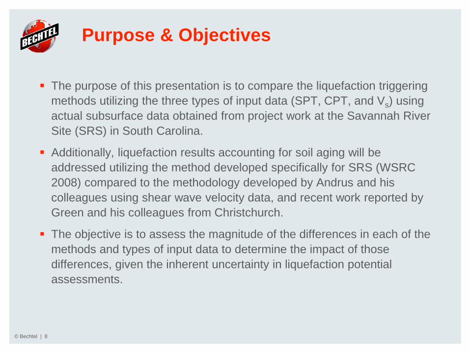
The purpose of this presentation is to compare the liquefaction triggering methods utilizing the three types of input data (SPT, CPT, and Vs) using actual subsurface data obtained from project work at the Savannah River Site (SRS) in South Carolina.
Additionally, liquefaction results accounting for soil aging will be addressed utilizing the method developed specifically for SRS (WSRC 2008) compared to the methodology developed by Andrus and his colleagues using shear wave velocity data, and recent work reported by Green and his colleagues from Christchurch.
The objective is to assess the magnitude of the differences in each of the methods and types of input data to determine the impact of those differences, given the inherent uncertainty in liquefaction potential assessments.

Liquefaction Triggering Methods (a brief background)
© Bechtel | 9

Liquefaction Triggering Methods
© Bechtel | 10
For the liquefaction triggering methods presented herein, the factor of safety against liquefaction is defined as:
– 𝐹𝐹𝐹𝐹 = 𝐶𝐶𝐶𝐶𝐶𝐶7.5𝐶𝐶𝐶𝐶𝐶𝐶
∗ 𝑀𝑀𝐹𝐹𝐹𝐹 ∗ 𝐾𝐾𝜎𝜎 ∗ 𝐾𝐾𝛼𝛼 ∗ 𝐾𝐾𝑎𝑎𝑎𝑎𝑎𝑎
– Where: » CSR is the earthquake demand » CRR is the soil’s capacity (resistance or strength) » MSF is the magnitude scaling factor » Kσ is a correction for overburden pressure » Kα is a correction for static shear stress (set to 1 for this comparison) » Kage is a correction for age (also known as KDR set to 1 for the comparison unless
otherwise noted)
Liquefaction triggering methods generally present a simplified method to approximate the CSR. Liquefaction triggering methods generally recommend the use of site response where proper data are available. For this presentation, the results of site response analyses were performed and are used as input CSR.

Liquefaction Triggering Methods
© Bechtel | 11
Recent changes/new developments – New fines content correction for BI2014 for CPTs.
– New magnitude scaling factor (MSF) based on dilational response or relative density have
been published by Cetin and Bilge (2012), Kishida and Tsai (2014), and BI2014. See these papers for details. This presentation will briefly discuss the MSF published by BI2014 for CPTs and SPTs.
– New/updated age corrections.

Fines Content Correction – CPT Cont.
𝑞𝑞𝑐𝑐𝑐𝑐𝑐𝑐𝑐𝑐𝑐 = 𝑞𝑞𝑐𝑐𝑐𝑐𝑐 + ∆𝑞𝑞𝑐𝑐𝑐𝑐𝑐 – BI2014
∆𝑞𝑞𝑐𝑐𝑐𝑐𝑐= 11.9 + 𝑞𝑞𝑐𝑐𝑐𝑐𝑐
𝑐4.6𝑒𝑒 𝑐.63− 9.7
𝐹𝐹𝐹𝐹+2−𝑐5.7𝐹𝐹𝐹𝐹+2
2
– BI2014
Figure 2.7a from BI2014
© Bechtel | 12

Fines Content Correction – CPT Cont.
© Bechtel | 13
Assumes Ic-apparent fines content correlation from Robertson and Wride (1998) for NCEER Moss does not allow for this type of comparison due to the dependence on CSR.

Fines Content Correction – SPT
© Bechtel | 14
0
5
10
15
20
25
30
0 10 20 30 40 50 60 70 80 90 100
Nor
mal
ized
Clea
n Sa
nd C
orre
cted
Blo
w C
ount
, (N
1)60
cs
Fines Content (%)
NCEER
IB2008 and BI2014
Cetin
5
10
15
20
(N1)60=

Magnitude Scaling Factor
IB2014 – “Magnitude scaling factor (MSF) relationships are used in liquefaction triggering correlations to approximately account for how the characteristics of the irregular cyclic loading produced by different magnitude earthquakes affect the potential for triggering of liquefaction.”
This can be shown as:
𝑀𝑀𝐹𝐹𝐹𝐹 =
𝐶𝐶𝐶𝐶𝐶𝐶𝑀𝑀𝐶𝐶𝐶𝐶𝐶𝐶𝑀𝑀=7.5
=𝑁𝑁𝑀𝑀=7.5𝑁𝑁𝑀𝑀
𝑏𝑏
– CRRM = CRR at a given magnitude – CRRM =7.5 = CRR at M=7.5 – NM=7.5 = number of uniform cycles for M = 7.5 – NM = number of uniform cycles for a given magnitude – b = fitting parameter
© Bechtel | 15

Magnitude Scaling Factor
© Bechtel | 16
As reported by BI2014

Magnitude Scaling Factor
© Bechtel | 17
Interpretation as reported by BI2014

Magnitude Scaling Factor
BI2014
𝑀𝑀𝐹𝐹𝐹𝐹 = 1 + 𝑀𝑀𝐹𝐹𝐹𝐹𝑚𝑚𝑎𝑎𝑚𝑚 − 1 8.64𝑒𝑒−𝑀𝑀4 −𝑐.325
Where:
– 𝑀𝑀𝐹𝐹𝐹𝐹𝑚𝑚𝑎𝑎𝑚𝑚 = 1.09 + 𝑞𝑞𝑐𝑐𝑐𝑐𝑐𝑐𝑐𝑐𝑐𝑐80
3≤ 2.2
Or:
– 𝑀𝑀𝐹𝐹𝐹𝐹𝑚𝑚𝑎𝑎𝑚𝑚 = 1.09 + 𝑐𝑐𝑐 60𝑐𝑐𝑐𝑐3𝑐.5
2≤ 2.2
© Bechtel | 18
From BI2014

Liquefaction Triggering Methods
© Bechtel | 19
Shear Wave Velocity

Shear Wave Velocity
© Bechtel | 20
Relations shown are for Holocene sands
0
0.1
0.2
0.3
0.4
0.5
0.6
100 120 140 160 180 200 220 240 260
CRR
Vs1 (m/s)
Kayen NCEER
Mw = 7.5σ'v0 = 100 kPaPL = 26%
Solid lines represent FC = 0%Dotted lines represent FC = 35%

Aging
© Bechtel | 21
Cyclic resistance has been shown to increase with time since initial deposition or last critical disturbance (also referred to as age).
𝐶𝐶𝐶𝐶𝐶𝐶𝑘𝑘 = 𝐶𝐶𝐶𝐶𝐶𝐶 ∗ 𝐾𝐾𝐷𝐷𝐶𝐶 – CRRk = Cyclic resistance ratio corrected for age and cementation – CRR = Cyclic resistance ratio uncorrected for age and cementation – KDR = Factor to correct for influence of age and cementation on deposit resistance, also
referred to as Kage

Aging – Andrus et al. (2009)
© Bechtel | 22
Andrus et al. (2009) suggest a method using the ratio of measured to estimated shear-wave velocity (MEVR) to calculate a correction factor for liquefaction resistance.
𝑀𝑀𝑀𝑀𝑀𝑀𝐶𝐶 = 𝑀𝑀𝑎𝑎𝑎𝑎𝑐𝑐𝑀𝑀𝑀𝑀𝑎𝑎𝑀𝑀 𝐶𝐶𝑆𝑎𝑎𝑎𝑎𝑀𝑀 𝑊𝑊𝑎𝑎𝑊𝑊𝑎𝑎 𝑉𝑉𝑎𝑎𝑉𝑉𝑉𝑉𝑐𝑐𝑉𝑉𝑉𝑉𝑉𝑉𝐸𝐸𝑐𝑐𝑉𝑉𝑉𝑉𝑚𝑚𝑎𝑎𝑉𝑉𝑎𝑎𝑀𝑀 𝐶𝐶𝑆𝑎𝑎𝑎𝑎𝑀𝑀−𝑊𝑊𝑎𝑎𝑊𝑊𝑎𝑎 𝑉𝑉𝑎𝑎𝑉𝑉𝑉𝑉𝑐𝑐𝑉𝑉𝑉𝑉𝑉𝑉 𝑏𝑏𝑎𝑎𝑐𝑐𝑎𝑎𝑀𝑀 𝑉𝑉𝑜𝑜 𝑃𝑃𝑎𝑎𝑜𝑜𝑎𝑎𝑉𝑉𝑀𝑀𝑎𝑎𝑉𝑉𝑉𝑉𝑉𝑉𝑜𝑜 𝐶𝐶𝑎𝑎𝑐𝑐𝑉𝑉𝑐𝑐𝑉𝑉𝑎𝑎𝑜𝑜𝑐𝑐𝑎𝑎
0
50
100
150
200
250
300
0 10 20 30 40 50 60
Nor
mal
ized
Clea
n Sa
nd S
hear
Wav
e Ve
loci
ty, (
V s1)
cs(m
/s)
Normalized Clean Sand Blow Count, (N1)60cs
0
50
100
150
200
250
300
0 50 100 150 200 250 300
Nor
mal
ized
Clea
n Sa
nd S
hear
Wav
e Ve
loci
ty, (
V s1)
cs(m
/s)
Normalized Clean Sand CPT Tip Resistance, (qt1N)cs

Aging – Andrus et al. (2009)
© Bechtel | 23
Example using inputs of (qt1N)cs = 125 and (V1s)cs = 245 m/s
0
50
100
150
200
250
300
0 50 100 150 200 250 300
Nor
mal
ized
Clea
n Sa
nd S
hear
Wav
e Ve
loci
ty, (
V s1)
cs(m
/s)
Normalized Clean Sand CPT Tip Resistance, (qt1N)cs
Measured (qt1N)cs results inexpected (Vs1)cs of 191 m/s
Measured (Vs1)cs of 245 m/s
MEVR= 245/191 = 1.28

Aging – Andrus et al. (2009)
© Bechtel | 24
Aging factor calculated using Andrus et al. (2009) – 𝐾𝐾𝐷𝐷𝐶𝐶 = 2.07 𝑀𝑀𝑀𝑀𝑀𝑀𝐶𝐶 − 1.11
The cyclic resistance ratio is then calculated using the equation below after Andrus et al. (2009)
– 𝐶𝐶𝐶𝐶𝐶𝐶 = 0.022 𝑉𝑉𝑐𝑐𝑐𝑐00 𝑀𝑀𝐸𝐸𝑉𝑉𝐶𝐶
2+ 2.8 𝑐
𝑉𝑉𝑐𝑐𝑐∗ −𝑉𝑉𝑐𝑐𝑐
𝑀𝑀𝑀𝑀𝑉𝑉𝑀𝑀
− 𝑐𝑉𝑉𝑐𝑐𝑐∗
𝐾𝐾𝐷𝐷𝐶𝐶
» Vs1 = normalized shear wave velocity » Vs1
* = » 215 m/s for FC ≤ 5% » 215-0.5(FC-5) m/s for 5% < FC ≤ 35% » 200 m/s for FC > 35%
Aging
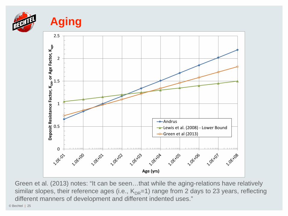
© Bechtel | 25
Green et al. (2013) notes: “It can be seen…that while the aging-relations have relatively similar slopes, their reference ages (i.e., KDR=1) range from 2 days to 23 years, reflecting different manners of development and different indented uses.”
0
0.5
1
1.5
2
2.5
Depo
sit R
esis
tanc
e Fa
ctor
, KDR
, or A
ge F
acto
r, K a
ge
Age (yrs)
AndrusLewis et al. (2008) - Lower BoundGreen et al (2013)

Evaluations at SRS
© Bechtel | 26

Site Evaluations at SRS
© Bechtel | 27
The seismic demand or cyclic stress ratio (CSR) through the soil column is calculated using a one dimensional site response analysis.
Two earthquakes are utilized – Deterministic
» Mw = 7.2; PGA = 0.1g Charleston 50th (C50)
– Probabilistic » Mw = 6.6, PGA = 0.2g Design Basis Event (PC3)

Site Evaluations at SRS
© Bechtel | 28
0
20
40
60
80
100
120
140
160
180
0.02 0.04 0.06 0.08 0.1
Dept
h (ft
)
Cyclic Stress Ratio, CSR
PC3
C50

SPT Results at SRS
© Bechtel | 29
0
20
40
60
80
100
120
140
160
0 1 2 3 4
Dept
h (ft
)
Factor of Safety, FS
S-G2-B02PC3 Seismic Input
NCEER
Cetin
IB2008
BI2014
0
20
40
60
80
100
120
140
160
0 1 2 3 4
Dept
h (ft
)
Factor of Safety, FS
S-G2-B02C50 Seismic Input
NCEER
Cetin
IB2008
BI2014
All four relations shown are for Holocene deposits

SPT Results at SRS
© Bechtel | 30
Combining results from three borings All relationships are for Holocene deposits
0
0.5
1
1.5
2
2.5
3
3.5
4
0 0.5 1 1.5 2 2.5 3 3.5 4
Fact
or o
f Saf
ety
usin
g Al
tern
ate
Met
hod
Factor of Safety using NCEER
Cetin
IB2008
BI2014
PC3 event represented by solid symbolsC50 event represented by hollow symbols

CPT Results at SRS
© Bechtel | 31 Only SRS accounts for age. All other relationships are for Holocene deposits
0
20
40
60
80
100
120
140
160
0 1 2 3 4
Dept
h (ft
)
Factor of Safety, FS
S-G2-C01PC3 Seismic Input
NCEER
Moss
IB2008
BI2014
SRS
0
20
40
60
80
100
120
140
160
0 1 2 3 4
Dept
h (ft
)
Factor of Safety, FS
S-G2-C01C50 Seismic Input
NCEER
Moss
IB2008
BI2014
SRS
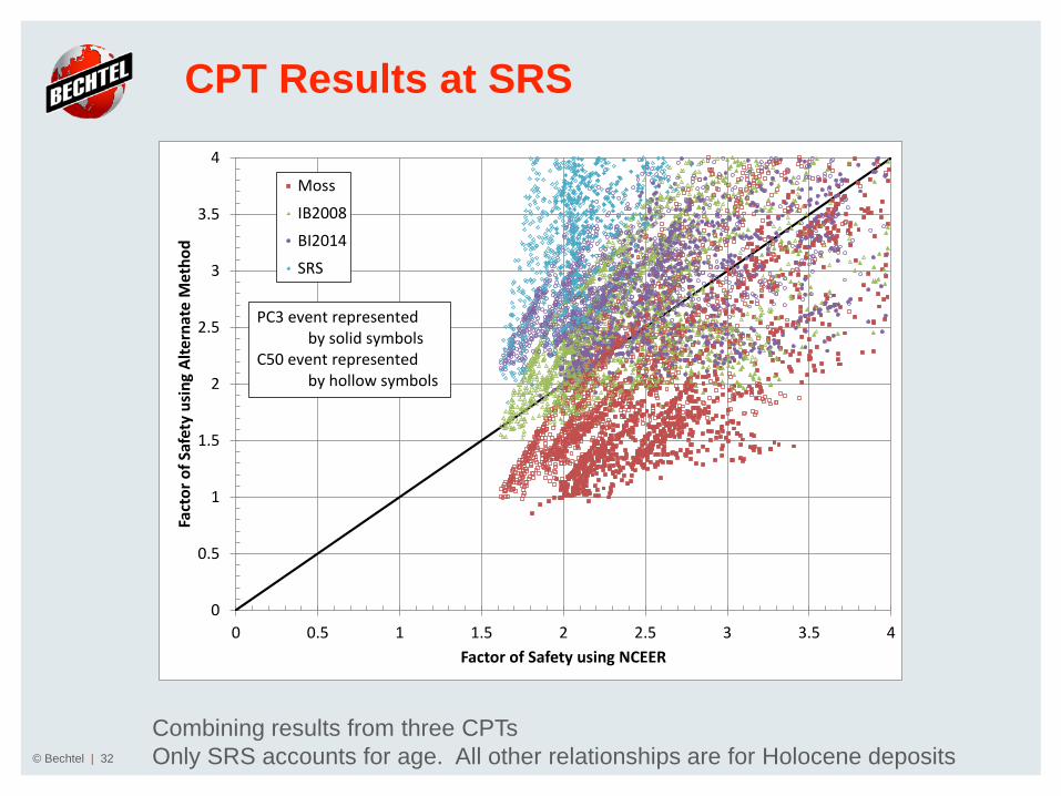
CPT Results at SRS
© Bechtel | 32
Combining results from three CPTs Only SRS accounts for age. All other relationships are for Holocene deposits
0
0.5
1
1.5
2
2.5
3
3.5
4
0 0.5 1 1.5 2 2.5 3 3.5 4
Fact
or o
f Saf
ety
usin
g Al
tern
ate
Met
hod
Factor of Safety using NCEER
Moss
IB2008
BI2014
SRS
PC3 event representedby solid symbols
C50 event representedby hollow symbols

Vs Results at SRS
© Bechtel | 33
0
20
40
60
80
100
120
140
160
0 2 4 6 8
Dept
h (ft
)
Factor of Safety, FS
S-G2-C09PC3 Seismic Input
NCEER
Kayen
Andrus
0
20
40
60
80
100
120
140
160
0 2 4 6 8
Dept
h (ft
)
Factor of Safety, FS
S-G2-C09C50 Seismic Input
NCEER
Kayen
Andrus
Only Andrus accounts for age. All other relationships are for Holocene deposits

Vs Results at SRS
© Bechtel | 34
0
0.5
1
1.5
2
2.5
3
3.5
4
0 0.5 1 1.5 2 2.5 3 3.5 4
Fact
or o
f Saf
tety
usi
ng A
ltern
ate
Met
hod
Factor of Safety using NCEER
AndrusKayen
PC3 event represented by solid symbolsC50 event represented by hollow symbols
Combining shear wave velocity results from three SCPTs Only Andrus accounts for age. All other relationships are for Holocene deposits

Age Corrections
© Bechtel | 35
Assumes Kage = 1.7 for BI2014
0
20
40
60
80
100
120
140
160
180
0 2 4 6 8
Dept
h (ft
)
Factor of Safety
S-G2-B03 & S-G2-C09PC3 Seismic Input
CPT - BI2014 - K_age CorrectedSPT - BI2014 - K_age CorrectedCPT - SRS (method accounts for age)Vs - Andrus (method accounts for age)
0
20
40
60
80
100
120
140
160
180
0 2 4 6 8
Dept
h (ft
)
Factor of Safety
S-G2-B03 & S-G2-C09C50 Seismic Input
CPT - BI2014 - K_age CorrectedSPT - BI2014 - K_age CorrectedCPT - SRS (method accounts for age)Vs - Andrus (method accounts for age)

Conclusions
© Bechtel | 36
Conclusions
© Bechtel | 37
Advancements in the calculation of magnitude scaling factor (MSF), aging, and fines content correction for the purposes of liquefaction calculations have been presented.
When accounting for age, the seismic input used result in factors of safety generally greater than 2 for the SRS site.
The SRS site-specific correlation continues to be appropriate and at the state of practice.

Conclusions
© Bechtel | 38
For the explorations examined and the seismic input motion used, factors of safety are generally distributed as follows: – Borings (SPTs)
» Using Holocene correlations without correction for age, Cetin has the lowest factor of safety followed by BI2014, IB2008, and NCEER with NCEER having the highest factor of safety.
– CPTs » Using Holocene correlations without correction for age, Moss has the lowest factor of
safety followed by IB2008, BI2014, and NCEER with NCEER having the highest factor of safety. When the SRS site specific relation is used, which accounts for age, the SRS relation results in the highest factor of safety.
» When an aging factor is applied to BI2014, the results are similar to those from SRS which accounts for age.
– Vs » Kayen and NCEER are Holocene correlations which result in similar factors of safety.
Andrus, which accounts for age, results in slightly lower factors of safety.

References
© Bechtel | 39

References
© Bechtel | 40
Andrus, R. D., & Stokoe II, K. H. (2000). Liquefaction resistance of soils from shear-wave velocity. Journal of Geotechnical and Geoenvironmental Engineering, 126(11), 1015-1025.
Andrus, R. D., Hayati, H., and Mohanan, N. P. (2009). “Correcting Liquefaction Resistance for Aged Sands Using Measured to Estimated Velocity Ratio.” Journal of Geotechnical and Geoenvironmental Engineering, ASCE, 135(6).
Boulanger, R. W., and Idriss, I. M. (2014). "CPT and SPT based liquefaction triggering procedures." Report No. UCD/CGM-14/01, Center for Geotechnical Modeling, Department of Civil and Environmental Engineering, University of California, Davis, CA, 134 pp.
Cetin, K.O., Seed, R.B., Der Kiureghian, A., Tokimatsu, K., Harder, L.F., Kayen, R.E., and Moss, R.E.S., 2004, “Standard Penetration Test-based Pprobabilistic and Deterministic Assessment of Seismic Soil Liquefaction Potential,” ASCE Journal of Geotechnical and Geoenvironmental Engineering, 130(12), 1314-1340.
Cetin, K. O., and Bilge, H. T. (2012). "Performance-based assessment of magnitude (duration) scaling factors." Journal of Geotechnical and Geoenvironmental Engineering, ASCE, 138: 324-334.
Green, R.A., Maurer, B.W., Bradley, B.A., Wotherspoon, L., and Cubrinovski, M. (2013). Implications from Liquefaction Observations in New Zealand for Interpreting Paleoliquefaction Data in the Central Eastern United States (CEUS). U.S. Geological Society Final Technical Report, Award No. G12AP20002.
Idriss, I.M., and Boulanger, R.W., 2008, Soil Liquefaction During Earthquakes, EERI MNO-12, 235 pp.
Kayen, R., Moss, R. E. S., Thompson, E. M., Seed, R. B., Cetin, K. O., Kiureghian, A. D., Tanaka, Y., & Tokimatsu, K. (2013). Shear-Wave Velocity–Based Probabilistic and Deterministic Assessment of Seismic Soil Liquefaction Potential. Journal of Geotechnical and Geoenvironmental Engineering, 139(3), 407-419.
Kishida, T., and Tsai, C.-C. (2014). "Seismic demand of the liquefaction potential with equivalent number of cycles for probabilistic seismic hazard analysis." Journal of Geotechnical and Geoenvironmental Engineering, ASCE, 10.1061/(ASCE)GT.1943-606.0001033.
Lewis, M. R., Arango, I., & McHood, M. D. (2008). Site characterization philosophy and liquefaction evaluation of aged sands—A Savannah river Site and Bechtel Perspective. In From Research to Practice in Geotechnical Engineering (pp. 540-558). ASCE.

References
© Bechtel | 41
Moss, R. E., Seed, R. B., Kayen, R. E., Stewart, J. P., Der Kiureghian, A., & Cetin, K. O. 2006. CPT-based probabilistic and deterministic assessment of in situ seismic soil liquefaction potential. Journal of Geotechnical and Geoenvironmental Engineering, 132(8), 1032-1051.
Rix, G. J., & Stokoe, K. H. (1991). Correlation of initial tangent modulus and cone penetration resistance. In International symposium on calibration chamber testing. Elsevier Publishing, New York (pp. 351-362).
Schnaid, F., Lehane, B. M., & Fahey, M. (2004). In situ test characterization of unusual geomaterials. Geotechnical and geophysical site characterization, 1, 49-74.
Schneider, J. A., & Moss, R. E. S. (2011). Linking cyclic stress and cyclic strain based methods for assessment of cyclic liquefaction triggering in sands. Géotechnique Letters, 1 (April-June), 31.
Schneider, J. A., Lehane, B. M. (2010) Evaluation of cone penetration test data from a calcareous dune sand, Proc. 2nd Intl. Symposium on Cone Penetration Testing, Vol. 2 (CPT’10), www.cpt10.com.
WSRC 2008, “Liquefaction Potential and Dynamic Settlement Guidance for Level Ground Conditions at the Savannah River Site,” WSRC Report K-ESR-G-00014, Rev. 0, 24 pp.
Youd, T.L., and Idriss, I.M., eds, 1997, NCEER Workshop on Evaluation of Liquefaction Resistance of Soils, National Center for Earthquake Engineering Research Technical Report NCEER-97-0022, 276 pp.
Youd, T.L., Idriss, I.M., Andrus, R.D., Arango, I., Castro, G., Christian, J.T., Dobry, R., Finn, W.D.L., Harder Jr., L.F., Hynes, M.E., Ishihara, K., Koestor, J.P., Liao, S.S.C., Marcuson III, W.F., Martin, G.R., Mitchell, J.K., Moriwaki, Y., Power, M.S., Robertson, P.K., Seed, R.B., and Stokoe II, K.H. (2001), “Liquefaction Resistance of Soils: Summary Report from the 1996 NCEER and 1998 NCEER/NSF Workshops on Evaluation of Liquefaction Resistance of Soils,” Journal of Geotechnical and Geoenvironmental Engineering, ASCE, 127(10), 817-833.
Youd, T.L., Idriss, I.M., Andrus, R.D., Arango, I., Castro, G., Christian, J.T., Dobry, R., Finn, W.D.L., Harder Jr., L.F., Hynes, M.E., Ishihara, K., Koestor, J.P., Liao, S.S.C., Marcuson III, W.F., Martin, G.R., Mitchell, J.K., Moriwaki, Y., Power, M.S., Robertson, P.K., Seed, R.B., and Stokoe II, K.H. (2003), Closure to “Liquefaction Resistance of Soils: Summary Report from the 1996 NCEER and 1998 NCEER/NSF Workshops on Evaluation of Liquefaction Resistance of Soils,” Journal of Geotechnical and Geoenvironmental Engineering, ASCE, 129(3), 284-286.

Questions
© Bechtel | 42