Embed Size (px)
Citation preview
Lingenfelter VSFM-002 Variable Speed DC Brushless
Fan & Pump Controller Instructions
Lingenfelter Performance Engineering1557 Winchester Road
Decatur, IN 46733(260) 724-2552
(260) 724-8761 faxwww.lingenfelter.com
Release date: 8 September 2016Revision - 1.8
PN: L460320002
Page 2
Parts ListLingenfelter VSFM-002 Variable Speed DC Brushless
Fan & Pump Controller (PN: L460320002)
# Description Part number1 Variable speed control module VSFM-0022 Hook & loop tape2 Self-tapping screw AV160371 LPE decal L9200100001 Instructions
Tools & Materials Required• Phillips head screwdriver• Wire crimping tool
Optional Items Description Part number
LPE technician’s screwdriver L950050000
Description:The Lingenfelter VSFM-002 is designed to provide the PWM speed control signal needed to operate variable speedOEMandaftermarketDCbrushlesscoolingfansandfluidcirculationpumps.Thespeedcanbecontrolledbasedonatemperatureinputsignal(e.g.ResistiveTemperatureDetector(RTD)orThermistor)orasimpleswitchedinputforon/offtypecontrol.TheVSFM-002alsohasarelaycontroloutputtocontrolawarninglightorauxiliarydevice.
• WorkswithOEMandaftermarketIAT,ECT,EGT,TFTsensorsincluding(moreonpage12):
• GMIAT(12160244/12614717)
• ECT(12608814/12636612)
• TFT(12458118)
• Oiltemperaturesensors(15326388)
• Bosch 2780071435, 2782569739, 2782650379, 2782610059, 0280130039
• AEM30-2012andothersimilarfluidtemperaturesensors
• WorkswithOEMandaftermarketEGT&platinumRTDsensors,including(moreonpage12):
• AEM 30-2050
• GM 12636612
• ACDelco 213-4695
• Bosch PT 200E
• Sensata TS200-A
• PT200RTD
• Works with OEM and aftermarket DC brushless electric fans & coolant pumps made/ sold by:
• GM,Bosch,CooperIndustries,Pierburg,andotherstobeadded.
• Works with SPAL OEM and aftermarket NUOVA DC brushless fans, including the “Standard Series” and thenewer“PlusSeries”fans.
The VSFM-002 can replace the following SPAL sensors: SBL-TS01, SBL-TS02, SBL-TS03, SBL-TS215P, SBL-TS185P,SBL-TS165P.
Page 3
Specifications• Two sets of easily adjustable device control switches
• “StartTemp”setstheinitialontemperatureforthedevice(s)
• “MaxOutputTemp”setsthetemperatureforthemaximumdevicespeed.
• The VSFM-002 provides a linear output speed control between these two settings
• Thesameswitchesarealsousedtosetspeed%indirectdevicespeedcontrolmode.
• Canbeusedtocontrolmultipledevices(alldevicesmustbethesameinputtype)
• Available output types:
• OutputshaveaselfprotectfeatureandwillturnOFFincaseofdirectshortorovercurrentcondition.
• Twofrequencybasedoutputwires(1-250Hz)
• Push-pull +12V peak output
• Open drain ground control type output
• RelayOutput-Therelaycontroloutputwilloutputagroundsignalwhenthefanisoperatingatmaximumspeed.Therelaycontroloutputisintendedtocontrolawarninglightorauxiliarydevice,suchasanadditionalfan.
• Outputratedforupto0.75Amps.
• Analog Output signal
• Outputananalog,0-5Volts,signalbasedontemperatureorfan/pumpspeed%.
• Sendtemperatureorfan/pumpspeedtoanECM,dataacquisitionsystem,oragauge.
• Oneinputmanualoverride/activationwireavailable(ACrelatedactivation,manualoverride,etc.):
• Inputsignalimpedance:100kOhms.
• +12VorgroundactivationsignalwiredeterminedbyaDIPswitchinsidethebackcover.
• The DIP switch enables and disables a pull-up resistor
• Pull-up enabled - ground activation
• Pull-up disabled - +12V activation
• Operatingvoltagerange:9.0to18.0volts.
• Currentdraw:(max4amps)0.1amppluscurrentdrawofdevicebeingcontrolled
• The temperature switch settings can be adjusted in 10 degree increments from 0 to 990 degrees.
• IAT, ECT, and TFT (thermistor) sensors are in Fahrenheit (F)
• EGT/platinum RTD sensors, due to the larger temperature range, are in Celsius (C).
• CustommoldedhightemperatureglassfilledNylon6enclosure.
• Fullyencapsulated(potted)constructionforincreaseddurability.
• Oneyearwarranty(fromdateofpurchase).
Page 4
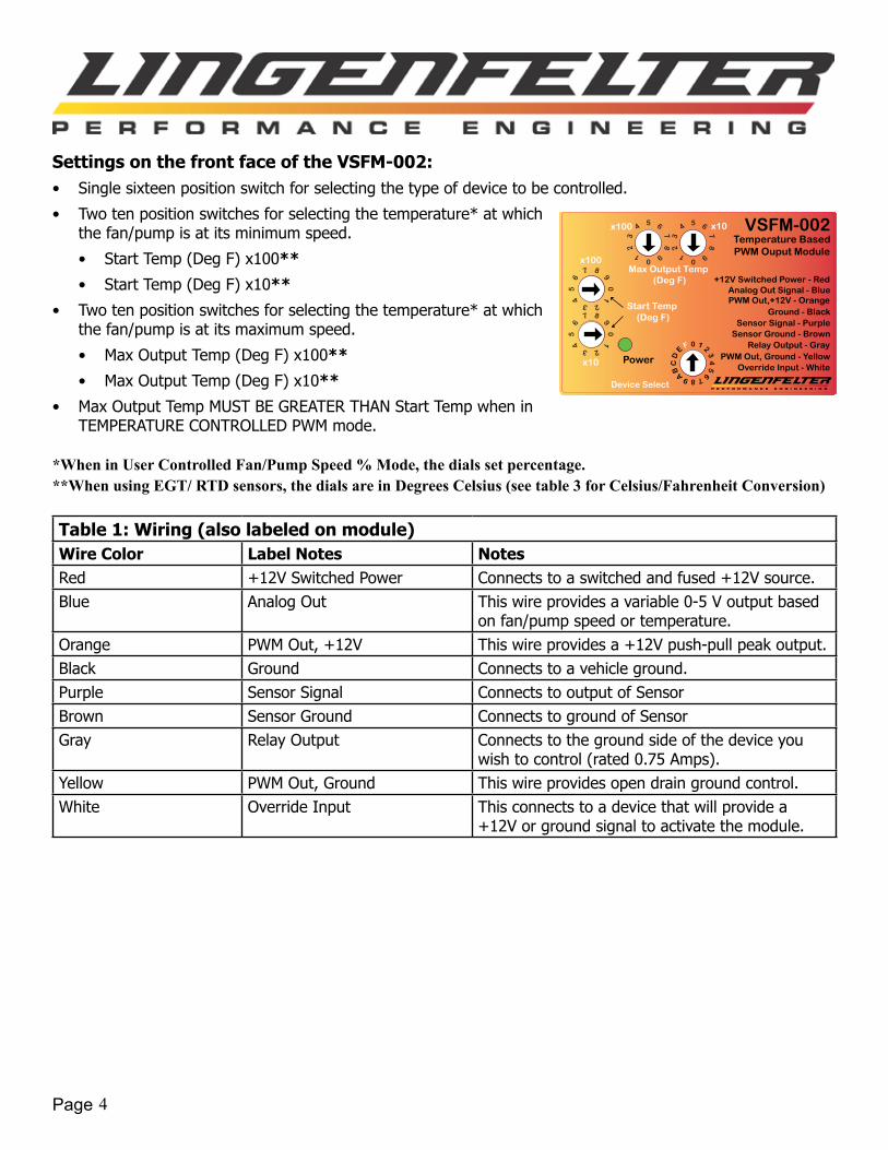
Settings on the front face of the VSFM-002:• Singlesixteenpositionswitchforselectingthetypeofdevicetobecontrolled.
• Two ten position switches for selecting the temperature* at which thefan/pumpisatitsminimumspeed.
• StartTemp(DegF)x100**
• StartTemp(DegF)x10**
• Two ten position switches for selecting the temperature* at which thefan/pumpisatitsmaximumspeed.
• MaxOutputTemp(DegF)x100**
• MaxOutputTemp(DegF)x10**
• MaxOutputTempMUSTBEGREATERTHANStartTempwheninTEMPERATURECONTROLLEDPWMmode.
*When in User Controlled Fan/Pump Speed % Mode, the dials set percentage.**When using EGT/ RTD sensors, the dials are in Degrees Celsius (see table 3 for Celsius/Fahrenheit Conversion)
Table 1: Wiring (also labeled on module)Wire Color Label Notes NotesRed +12V Switched Power Connectstoaswitchedandfused+12Vsource.Blue Analog Out This wire provides a variable 0-5 V output based
onfan/pumpspeedortemperature.Orange PWM Out, +12V Thiswireprovidesa+12Vpush-pullpeakoutput.Black Ground Connectstoavehicleground.Purple Sensor Signal Connects to output of SensorBrown Sensor Ground Connects to ground of SensorGray RelayOutput Connects to the ground side of the device you
wishtocontrol(rated0.75Amps).Yellow PWM Out, Ground Thiswireprovidesopendraingroundcontrol.White Override Input This connects to a device that will provide a
+12Vorgroundsignaltoactivatethemodule.
Power
VSFM-002Temperature BasedPWM Ouput Module
Ground - Black
Relay Output - GrayPWM Out, Ground - Yellow
x100
x10
+12V Switched Power - Red
Start Temp (Deg F)
x10x100
Max Output Temp (Deg F)
Sensor Signal - Purple
PWM Out,+12V - Orange
Override Input - White
Analog Out Signal - Blue
Sensor Ground - Brown
Device Select
Page 5
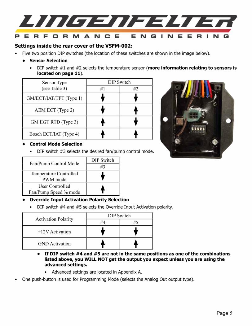
Settings inside the rear cover of the VSFM-002:• FivetwopositionDIPswitches(thelocationoftheseswitchesareshownintheimagebelow).
• Sensor Selection
• DIP switch #1 and #2 selects the temperature sensor (more information relating to sensors is located on page 11).
Sensor Type(see Table 3)
DIP Switch#1 #2
GM/ECT/IAT/TFT (Type 1)
AEM ECT (Type 2)
GM EGT RTD (Type 3)
Bosch ECT/IAT (Type 4)
• Control Mode Selection
• DIPswitch#3selectsthedesiredfan/pumpcontrolmode.
Fan/Pump Control ModeDIP Switch
#3Temperature Controlled
PWM modeUser Controlled
Fan/Pump Speed % mode• Override Input Activation Polarity Selection
• DIPswitch#4and#5selectstheOverrideInputActivationpolarity.
Activation PolarityDIP Switch
#4 #5
+12V Activation
GND Activation
• If DIP switch #4 and #5 are not in the same positions as one of the combinations listed above, you WILL NOT get the output you expect unless you are using the advanced settings.
• AdvancedsettingsarelocatedinAppendixA.
• Onepush-buttonisusedforProgrammingMode(selectstheAnalogOutoutputtype).
Page 6
Push-Button Programming Mode:ProgrammingmodeisusedtoprogramtheAnalogOutoutputontheVSFM-002.TherearetwooptionsfortheAnalogOutoutput.TheVSFM-002canoutputananalogvoltagebasedoneithertemperatureorfan/pumpspeed.
IfyouarenotplanningonusingtheAnalogOutoutput,youdonotneedtoprogramthisfeature.• The default Analog Out output is temperature based.
• When the temperature option is selected, the Analog Out will output a 0-5V(+/-0.02V)linearanalogsignaldependentonthetemperaturesensoryouhavechosen(moreinformationonpage11and12).
• GM ECT/IAT/TFT, AEM ECT, and the Bosch IAT/ECT sensors:
• 0.02V≈1.4DegF
• 0-350 Deg F
• 0.00V=0DegF
• 5.00V=350DegF
• GM/AEM/Bosch/SensataEGTPlatinumRTDsensors:
• 0.02V≈5DegC(9.1DegF)
• 0-1275 Deg C
• 0.00V=0DegC(32DegF)
• 5.00V=1275DegC(2327DegF)
• Whenthespeedoptionisselected,theAnalogOutwilloutputa0-5V(+/-0.02V)linearanalogsignaldependentonthecurrentspeed(0-100%)ofthefan/pump.AnalogOutwilloutput0.00Vat0%,andAnalogOutwilloutput5.00Vat100%.
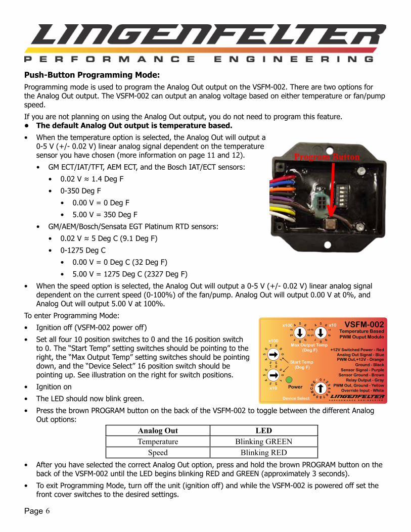
To enter Programming Mode:
• Ignitionoff(VSFM-002poweroff)
• Set all four 10 position switches to 0 and the 16 position switch to0.The“StartTemp”settingswitchesshouldbepointingtotheright, the “Max Output Temp” setting switches should be pointing down, and the “Device Select” 16 position switch should be pointingup.Seeillustrationontherightforswitchpositions.
• Ignition on
• TheLEDshouldnowblinkgreen.
• PressthebrownPROGRAMbuttononthebackoftheVSFM-002totogglebetweenthedifferentAnalogOut options:
Analog Out LEDTemperature Blinking GREEN
Speed Blinking RED• AfteryouhaveselectedthecorrectAnalogOutoption,pressandholdthebrownPROGRAMbuttononthe
backoftheVSFM-002untiltheLEDbeginsblinkingREDandGREEN(approximately3seconds).
• ToexitProgrammingMode,turnofftheunit(ignitionoff)andwhiletheVSFM-002ispoweredoffsetthefrontcoverswitchestothedesiredsettings.
Power
VSFM-002Temperature BasedPWM Ouput Module
Ground - Black
Relay Output - GrayPWM Out, Ground - Yellow
x100
x10
+12V Switched Power - Red
Start Temp (Deg F)
x10x100
Max Output Temp (Deg F)
Sensor Signal - Purple
PWM Out,+12V - Orange
Override Input - White
Analog Out Signal - Blue
Sensor Ground - Brown
Device Select
Program Button
Page 7
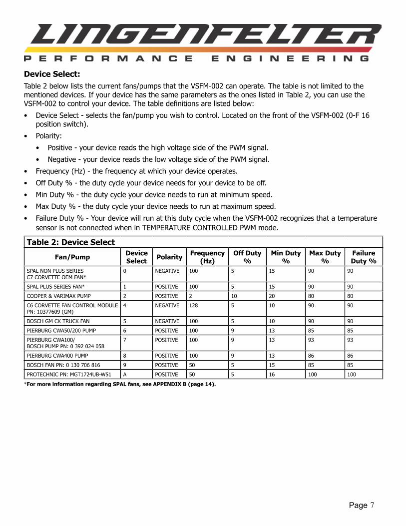
Device Select:Table2belowliststhecurrentfans/pumpsthattheVSFM-002canoperate.Thetableisnotlimitedtothementioneddevices.IfyourdevicehasthesameparametersastheoneslistedinTable2,youcanusetheVSFM-002tocontrolyourdevice.Thetabledefinitionsarelistedbelow:
• DeviceSelect-selectsthefan/pumpyouwishtocontrol.LocatedonthefrontoftheVSFM-002(0-F16positionswitch).
• Polarity:
• Positive-yourdevicereadsthehighvoltagesideofthePWMsignal.
• Negative-yourdevicereadsthelowvoltagesideofthePWMsignal.
• Frequency(Hz)-thefrequencyatwhichyourdeviceoperates.
• OffDuty%-thedutycycleyourdeviceneedsforyourdevicetobeoff.
• MinDuty%-thedutycycleyourdeviceneedstorunatminimumspeed.
• MaxDuty%-thedutycycleyourdeviceneedstorunatmaximumspeed.
• Failure Duty % - Your device will run at this duty cycle when the VSFM-002 recognizes that a temperature sensorisnotconnectedwheninTEMPERATURECONTROLLEDPWMmode.
Table 2: Device Select
Fan/Pump Device Select Polarity Frequency
(Hz)Off Duty
%Min Duty
%Max Duty
%Failure Duty %
SPALNONPLUSSERIESC7CORVETTEOEMFAN*
0 NEGATIVE 100 5 15 90 90
SPALPLUSSERIESFAN* 1 POSITIVE 100 5 15 90 90
COOPER&VARIMAXPUMP 2 POSITIVE 2 10 20 80 80
C6CORVETTEFANCONTROLMODULEPN:10377609(GM)
4 NEGATIVE 128 5 10 90 90
BOSCHGMCKTRUCKFAN 5 NEGATIVE 100 5 10 90 90
PIERBURGCWA50/200PUMP 6 POSITIVE 100 9 13 85 85
PIERBURGCWA100/BOSCH PUMP PN: 0 392 024 058
7 POSITIVE 100 9 13 93 93
PIERBURGCWA400PUMP 8 POSITIVE 100 9 13 86 86
BOSCH FAN PN: 0 130 706 816 9 POSITIVE 50 5 15 85 85
PROTECHNICPN:MGT1724UB-W51 A POSITIVE 50 5 16 100 100
*For more information regarding SPAL fans, see APPENDIX B (page 14).
Page 8
Temperature Controlled PWM Mode:ToenterTemperatureControlledPWMMode,DIPswitch#3mustbeintheDOWNposition.
Device operation:TheTemperatureControlledPWMmodeiscontrolledbytemperature.Thespeedofthefan/pumpwillincreaselinearlywithinputtemperaturesbetweenStartTempandMaxOutputTemp.WhentheinputtemperatureislessthanStartTemp,thefan/pumpwillbeoff.WhentheinputtemperatureisequaltoStartTemp,thefan/pumpwilloperateatminimumspeed.WhentheinputtemperatureisgreaterthanorequaltotheMaxOutputTemp,thefan/pumpwilloperateatmaximumspeed.
WhentheOverrideInputisactivated,thefan/pumpwilloperateatmaximumspeed.IftheVSFM-002recognizesthatatemperaturesensorisnotconnected,thecontrollerwillgointofailuremode.Failuremodewillcausethefan/pumptorunatmaximumspeed.
RelayOutputWire-Therelaycontroloutputwilloutputagroundsignalwhenthefanisoperatingatmaximumspeed.Therelaycontroloutputisintendedtocontrolawarninglightorauxiliarydevice.
LED operation:• SolidREDindicatesthatthefan/pumpisoff.• SolidGREENindicatesthattheinputtemperatureisbetweenStartTempandMaxOutputTemp(fan/pump
operatingrange).• BlinkingGREENindicatesthattheinputtemperatureisgreaterthanorequaltoMaxOutputTemp(fan/
pumpmaxspeed).• BlinkingREDandGREENindicatesthattheOverrideinputinactive(fan/pumpmaxspeed).• BlinkingREDindicatesthatStartTempisgreaterthanorequaltoMaxOutputTemp,orthereisno
temperaturesensorconnectedtotheVSFM-002.
Page 9
User Controlled Fan/Pump Speed % Mode:ToenterUserControlledFan/PumpSpeed%Mode,DIPswitch#3mustbeintheUPposition.
Note - You will only need a temperature sensor in this mode if you are using Analog Out to output a 0-5 V signalbasedontemperature.Thetemperaturesensordoesnotcontrolthespeedofthefan.
Speed Control:
• 0%isoff.
• 1%isminimumspeed.
• 99%iscontrolleroutputmaximumspeed.
• Actualspeedpercentageis+/-1%.
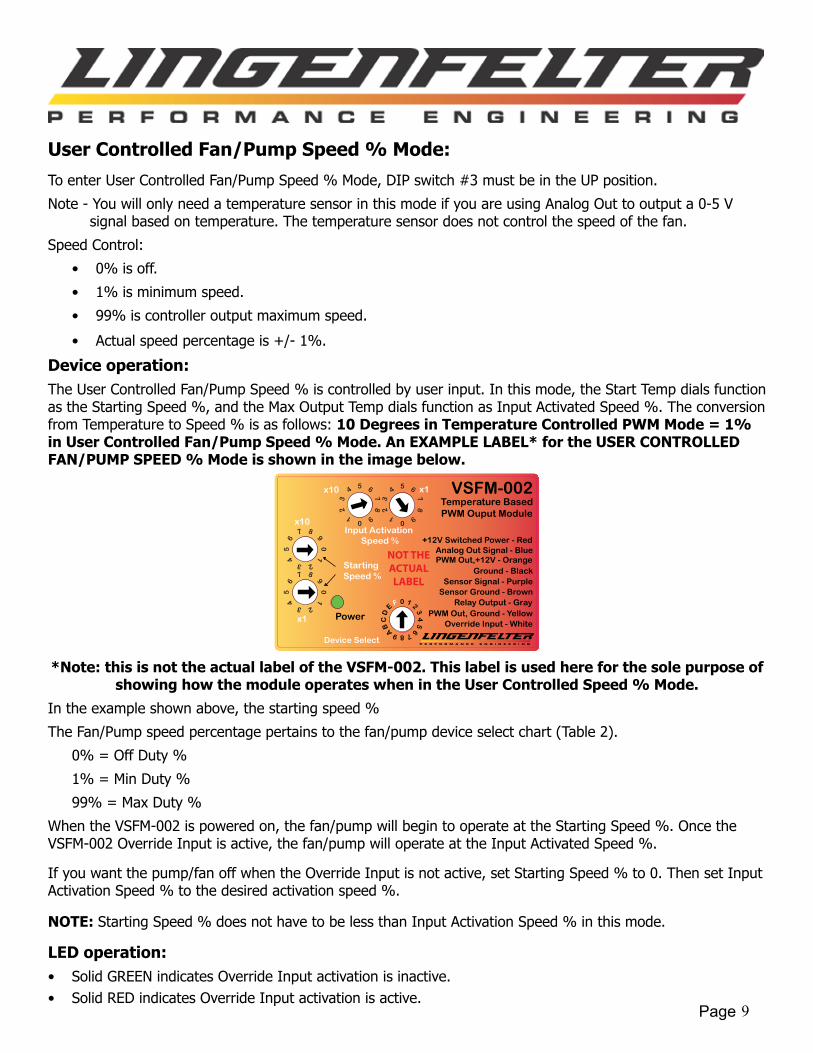
Device operation:TheUserControlledFan/PumpSpeed%iscontrolledbyuserinput.Inthismode,theStartTempdialsfunctionastheStartingSpeed%,andtheMaxOutputTempdialsfunctionasInputActivatedSpeed%.Theconversionfrom Temperature to Speed % is as follows: 10 Degrees in Temperature Controlled PWM Mode = 1% in User Controlled Fan/Pump Speed % Mode. An EXAMPLE LABEL* for the USER CONTROLLED FAN/PUMP SPEED % Mode is shown in the image below.
Power
VSFM-002Temperature BasedPWM Ouput Module
Ground - Black
Relay Output - GrayPWM Out, Ground - Yellow
x10
x1
+12V Switched Power - Red
Starting Speed %
x1x10
Input Activation Speed %
Sensor Signal - Purple
PWM Out,+12V - Orange
Override Input - White
Analog Out Signal - Blue
Sensor Ground - Brown
NOT THE ACTUAL LABEL
Device Select
*Note: this is not the actual label of the VSFM-002. This label is used here for the sole purpose of showing how the module operates when in the User Controlled Speed % Mode.
In the example shown above, the starting speed %
TheFan/Pumpspeedpercentagepertainstothefan/pumpdeviceselectchart(Table2).
0%=OffDuty%
1%=MinDuty%
99%=MaxDuty%
WhentheVSFM-002ispoweredon,thefan/pumpwillbegintooperateattheStartingSpeed%.OncetheVSFM-002OverrideInputisactive,thefan/pumpwilloperateattheInputActivatedSpeed%.
Ifyouwantthepump/fanoffwhentheOverrideInputisnotactive,setStartingSpeed%to0.ThensetInputActivationSpeed%tothedesiredactivationspeed%.
NOTE: StartingSpeed%doesnothavetobelessthanInputActivationSpeed%inthismode.
LED operation:• SolidGREENindicatesOverrideInputactivationisinactive.• SolidREDindicatesOverrideInputactivationisactive.
Page 10
Installation:1. Disconnectthenegativebatteryterminal.2. ConnecttheblackwireofVSFM-002tooasuitablevehicleground.Failure to fully secure the ground
wire to a vehicle ground source could result in malfunction of the module.3. Connect the red wire to a switched and fused+12voltDCsource.A5-10ampfuseshouldbesufficient.4. ConnectthegrayRelayOutputwiretothegroundsideofthedeviceyouwishtocontrol.
• Arelayshouldbeusediftherelaycontroloutputwillbecontrollingadevicethatpullsmorethan0.75amps.
5. ConfiguretheDIPswitchsettingsbehindthebackcoveroftheVSFM-002.6. ConnectthePurpleandBrownWiretoatemperaturesensor.7. ConnectthewhitewiretoadesiredactivationsourceifusingtheOverrideInput.8. ConnectthePWMsignalwiretothefan/pumpyouwillbecontrolling(seeTable2onpage7).
• If the fan/pump you are connecting to has an internal pull-up resistor, connect the yellow PWM Out, Ground,tothePWMinputonthefan/pump.
• If the fan/pump you are connecting to does not have an internal pull-up resistor, connect the orange PWMOut,+12V,tothePWMinputofthefan/pump.
9. SecuretheVSFM-002usingthesuppliedhookandlooptapeorusingthesuppliedself-tappingscrews.10.AdjustthedialsonthefrontoftheVSFM-002todesiredsettings.11.Reconnectthenegativebatteryterminal.
Additional Notes and Warnings:• ChangestotheswitchsettingsmustbedonewiththeVSFM-002poweredoff.
• Theswitchpositionsareonlyreadonstartup(initialdevicepowerup).
• ThelowTemperatureSetting(StartTemp)mustbelessthanthehighTemperatureSetting(MaxOutputTemp)wheninTemperatureControlledPWMMode.
• The VSFM-002 will not work on fans/pumps that require more than 250 Hz or less than 1 Hz for the PWM signal.
• MakesurethattheVSFM-002groundwireisproperlysecuredtoavehicleground.FailuretofullysecuretheVSFM-002groundwiretoavehiclegroundsourcecouldcausetheVSFM-002tomalfunction.
• DoNOTsubmergethemoduleinliquidordirectlywashtheunitwithliquidofanytype.Theswitchesonthe VSFM-002 are sealed but are NOT rated for high pressure washing, use caution if power washing near theVSFM-002module.
• Do NOT mount the VSFM-002 directly on top of the engine or near the exhaust manifolds due to heat concerns.
• Do NOT mount the VSFM-002 in the line of site of high temperature objects such as exhaust manifolds, turbinehousings,etc...Ifneeded,installaheatshieldinbetweentheheatsourceandthemoduletoprotecttheplasticcase.
• DoNOTinstallwithin6”ofnitroussolenoidsorotherdeviceswithstrongmagneticfields.
• Do NOT install near the spark plugs or the spark plug wires (or other potential strong sources of electrical noise).
• LPErecommendstheuseofresistortypesparkplugsandRFI(radiofrequencyinterference)andEMI(ElectromagneticInterference)suppressionsparkplugwiresonallEFIenginesandanyvehiclethathaselectroniccontrolmodulesonboard(includingtheVSFM-002).Failuretodosomayresultinerraticoperation of electronic device
Page 11
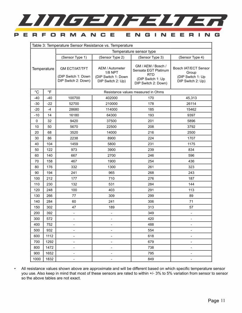
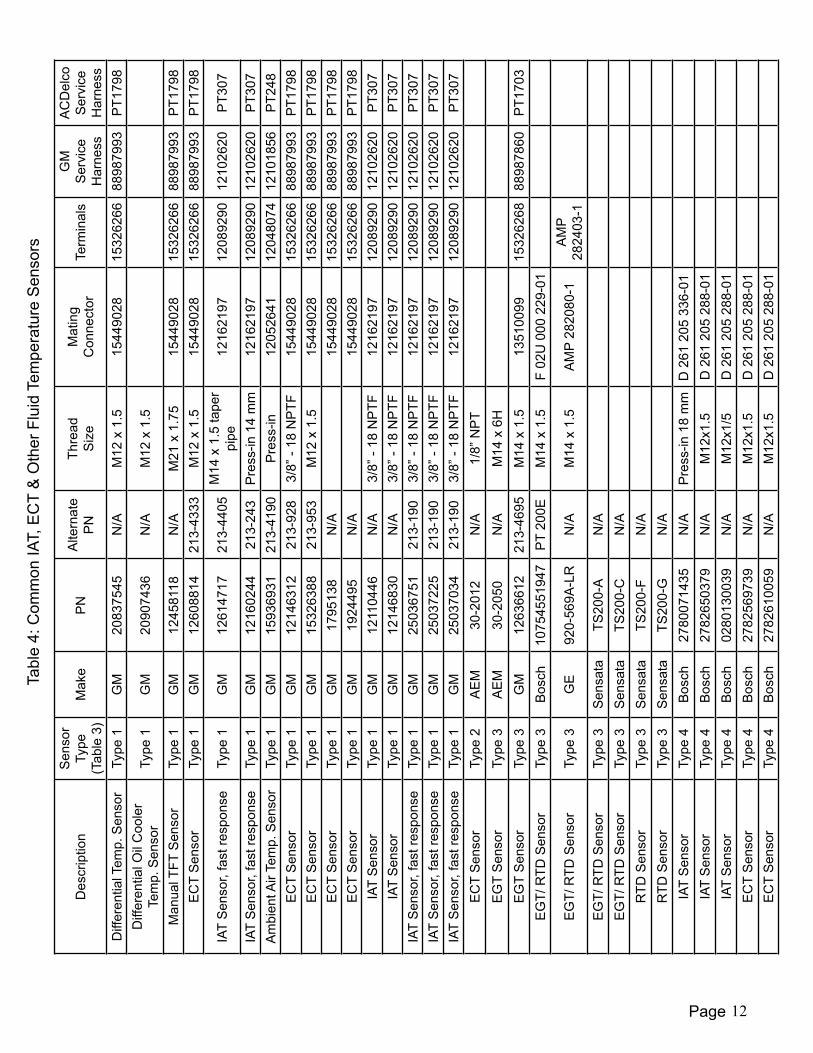
Table 3: Temperature Sensor Resistance vs. Temperature
Temperature
Temperature sensor type(Sensor Type 1) (Sensor Type 2) (Sensor Type 3) (Sensor Type 4)
GM ECT/IAT/TFT
(DIP Switch 1: DownDIP Switch 2: Down)
AEM / Autometer 1/8 NPT
(DIP Switch 1: DownDIP Switch 2: Up)
GM / AEM / Bosch / Sensata EGT Platinum
RTD (DIP Switch 1: Up
DIP Switch 2: Down)
Bosch IAT/ECT Sensor Group
(DIP Switch 1: UpDIP Switch 2: Up)
°C °F Resistance values measured in Ohms-40 -40 100700 402000 170 45,313-30 -22 52700 210000 178 26114-20 -4 28680 114000 185 15462-10 14 16180 64300 193 93970 32 9420 37500 201 5896
10 50 5670 22500 208 379220 68 3520 14000 216 250030 86 2238 8900 224 170740 104 1459 5800 231 117550 122 973 3900 239 83460 140 667 2700 246 59670 158 467 1900 254 43680 176 332 1300 261 32390 194 241 965 268 243
100 212 177 710 276 187110 230 132 531 284 144120 248 100 403 291 113130 266 77 309 299 89140 284 60 241 306 71150 302 47 189 313 57200 392 - - 349 -300 572 - - 420 -400 752 - - 488 -500 932 - - 554 -600 1112 - - 618 -700 1292 - - 679 -800 1472 - - 738 -900 1652 - - 795 -
1000 1832 - - 849 -
• Allresistancevaluesshownaboveareapproximateandwillbedifferentbasedonwhichspecifictemperaturesensoryou use. Also keep in mind that most of these sensors are rated to within +/- 3% to 5% variation from sensor to sensor so the above tables are not exact.
Des
crip
tion
Sen
sor
Type
(Tab
le 3
)M
ake
PN
Alte
rnat
eP
NTh
read
Siz
eM
atin
gC
onne
ctor
Term
inal
sG
M
Ser
vice
H
arne
ss
AC
Del
co
Ser
vice
H
arne
ssD
iffer
entia
l Tem
p. S
enso
rTy
pe 1
GM
2083
7545
N/A
M12
x 1
.515
4490
2815
3262
6688
9879
93P
T179
8D
iffer
entia
l Oil
Coo
ler
Tem
p. S
enso
rTy
pe 1
GM
2090
7436
N/A
M12
x 1
.5
Man
ual T
FT S
enso
rTy
pe 1
GM
1245
8118
N/A
M21
x 1
.75
1544
9028
1532
6266
8898
7993
PT1
798
EC
T S
enso
rTy
pe 1
GM
1260
8814
213-
4333
M12
x 1
.515
4490
2815
3262
6688
9879
93P
T179
8
IAT
Sen
sor,
fast
resp
onse
Type
1G
M12
6147
1721
3-44
05M
14 x
1.5
tape
r pi
pe12
1621
9712
0892
9012
1026
20P
T307
IAT
Sen
sor,
fast
resp
onse
Type
1G
M12
1602
4421
3-24
3P
ress
-in 1
4 m
m12
1621
9712
0892
9012
1026
20P
T307
Am
bien
t Air
Tem
p. S
enso
rTy
pe 1
GM
1593
6931
213-
4190
Pre
ss-in
1205
2641
1204
8074
1210
1856
PT2
48E
CT
Sen
sor
Type
1G
M12
1463
1221
3-92
83/
8” -
18 N
PTF
1544
9028
1532
6266
8898
7993
PT1
798
EC
T S
enso
rTy
pe 1
GM
1532
6388
213-
953
M12
x 1
.515
4490
2815
3262
6688
9879
93P
T179
8E
CT
Sen
sor
Type
1G
M17
9513
8N
/A15
4490
2815
3262
6688
9879
93P
T179
8E
CT
Sen
sor
Type
1G
M19
2449
5N
/A15
4490
2815
3262
6688
9879
93P
T179
8IA
T S
enso
rTy
pe 1
GM
1211
0446
N/A
3/8”
- 18
NP
TF12
1621
9712
0892
9012
1026
20P
T307
IAT
Sen
sor
Type
1G
M12
1468
30N
/A3/
8” -
18 N
PTF
1216
2197
1208
9290
1210
2620
PT3
07IA
T S
enso
r, fa
st re
spon
seTy
pe 1
GM
2503
6751
213-
190
3/8”
- 18
NP
TF12
1621
9712
0892
9012
1026
20P
T307
IAT
Sen
sor,
fast
resp
onse
Type
1G
M25
0372
2521
3-19
03/
8” -
18 N
PTF
1216
2197
1208
9290
1210
2620
PT3
07IA
T S
enso
r, fa
st re
spon
seTy
pe 1
GM
2503
7034
213-
190
3/8”
- 18
NP
TF12
1621
9712
0892
9012
1026
20P
T307
EC
T S
enso
rTy
pe 2
AE
M30
-201
2N
/A1/
8” N
PT
EG
T S
enso
rTy
pe 3
AE
M30
-205
0N
/AM
14 x
6H
EG
T S
enso
rTy
pe 3
GM
1263
6612
213-
4695
M14
x 1
.513
5100
9915
3262
6888
9878
60P
T170
3E
GT/
RTD
Sen
sor
Type
3B
osch
1075
4551
947
PT
200E
M14
x 1
.5F
02U
000
229
-01
EG
T/ R
TD S
enso
rTy
pe 3
GE
920-
569A
-LR
N/A
M14
x 1
.5A
MP
2820
80-1
AM
P 28
2403
-1E
GT/
RTD
Sen
sor
Type
3S
ensa
taTS
200-
AN
/AE
GT/
RTD
Sen
sor
Type
3S
ensa
taTS
200-
CN
/AR
TD S
enso
rTy
pe 3
Sen
sata
TS20
0-F
N/A
RTD
Sen
sor
Type
3S
ensa
taTS
200-
GN
/AIA
T S
enso
rTy
pe 4
Bos
ch27
8007
1435
N/A
Pre
ss-in
18
mm
D 2
61 2
05 3
36-0
1IA
T S
enso
rTy
pe 4
Bos
ch27
8265
0379
N/A
M12
x1.5
D 2
61 2
05 2
88-0
1IA
T S
enso
rTy
pe 4
Bos
ch02
8013
0039
N/A
M12
x1/5
D 2
61 2
05 2
88-0
1E
CT
Sen
sor
Type
4B
osch
2782
5697
39N
/AM
12x1
.5D
261
205
288
-01
EC
T S
enso
rTy
pe 4
Bos
ch27
8261
0059
N/A
M12
x1.5
D 2
61 2
05 2
88-0
1
Tabl
e 4:
Com
mon
IAT,
EC
T &
Oth
er F
luid
Tem
pera
ture
Sen
sors
Page 12
Page 13
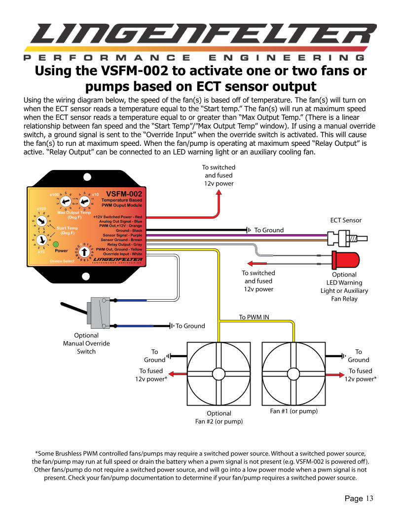
Using the VSFM-002 to activate one or two fans or pumps based on ECT sensor output
Usingthewiringdiagrambelow,thespeedofthefan(s)isbasedoffoftemperature.Thefan(s)willturnonwhentheECTsensorreadsatemperatureequaltothe“Starttemp.”Thefan(s)willrunatmaximumspeedwhentheECTsensorreadsatemperatureequaltoorgreaterthan“MaxOutputTemp.”(Thereisalinearrelationshipbetweenfanspeedandthe“StartTemp”/”MaxOutputTemp”window).Ifusingamanualoverrideswitch,agroundsignalissenttothe“OverrideInput”whentheoverrideswitchisactivated.Thiswillcausethefan(s)torunatmaximumspeed.Whenthefan/pumpisoperatingatmaximumspeed“RelayOutput”isactive.“RelayOutput”canbeconnectedtoanLEDwarninglightoranauxiliarycoolingfan.
To switched and fused 12v power
To switched and fused 12v power
To Ground
To Ground
ECT Sensor
OptionalFan #2 (or pump)
Fan #1 (or pump)
To Ground
To Ground
Power
VSFM-002Temperature BasedPWM Ouput Module
Ground - Black
Relay Output - GrayPWM Out, Ground - Yellow
x100
x10
+12V Switched Power - Red
Start Temp (Deg F)
x10x100
Max Output Temp (Deg F)
Sensor Signal - Purple
PWM Out,+12V - Orange
Override Input - White
Analog Out Signal - Blue
Sensor Ground - Brown
Device Select
To fused 12v power*
To fused 12v power*
To PWM IN
OptionalManual Override
Switch
OptionalLED Warning
Light or Auxiliary Fan Relay
*Some Brushless PWM controlled fans/pumps may require a switched power source. Without a switched power source, the fan/pump may run at full speed or drain the battery when a pwm signal is not present (e.g. VSFM-002 is powered o�). Other fans/pump do not require a switched power source, and will go into a low power mode when a pwm signal is not
present. Check your fan/pump documentation to determine if your fan/pump requires a switched power source.

Page 14
APPENDIX AAdvanced Settings:The advanced settings affect the Temperature Controlled PWM mode and the User Controlled Fan/Pump Speed %Mode.
When DIP switch #4 and #5 ARE NOT positioned in the same direction, the Override Input logic is reversed.
• Insteadofthefan/pumpoperatingatmaxspeed(TemperatureControlledPWMMode)orInputActivationSpeed%(UserControlledFan/PumpSpeed%Mode)whenthereisanOverrideInputActivation signal present, the fan/pump will operate at full speed or Input Activation % when an OverrideInputActivationsignalisnotpresent.
• Thetablesbelowshowthecorrespondingoutputsdependingonthedifferentinputcombinations.
TemperatureControlledPWMmode(Page8):
Input Output
Activation PolarityDIP Switch Override
Input PresentFan/Pump
Speed LED#4 #5
+12V Activation
NO Normal Operation
YES Max Speed Blinking RED/GREEN
NO Max Speed BlinkingRED/GREEN
YES Normal Operation
Ground Activation
NO Normal Operation
YES Max Speed BlinkingRED/GREEN
NO Max Speed BlinkingRED/GREEN
YES Normal OperationUserControlledFan/PumpSpeed%Mode(Page9):
• (Speed1%)refersto(StartingSpeed%),and(Speed2%)refersto(InputActivationSpeed%).
Input Output
Activation PolarityDIP Switch Override
Input PresentFan/Pump
Speed LED#4 #5
+12V Activation
NO Speed1 % GREENYES Speed2 % REDNO Speed2 % REDYES Speed1 % GREEN
Ground Activation
NO Speed1 % GREENYES Speed2 % REDNO Speed2 % REDYES Speed1 % GREEN
Page 15
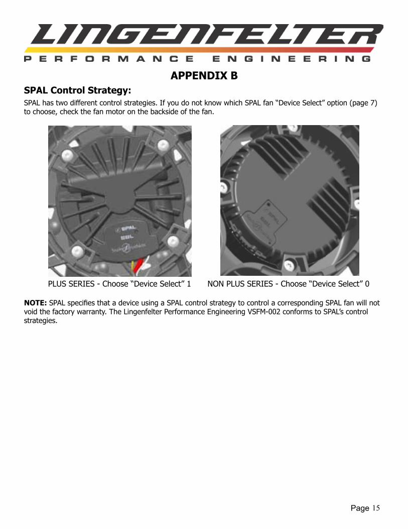
APPENDIX BSPAL Control Strategy:SPALhastwodifferentcontrolstrategies.IfyoudonotknowwhichSPALfan“DeviceSelect”option(page7)tochoose,checkthefanmotoronthebacksideofthefan.
NOTE: SPALspecifiesthatadeviceusingaSPALcontrolstrategytocontrolacorrespondingSPALfanwillnotvoidthefactorywarranty.TheLingenfelterPerformanceEngineeringVSFM-002conformstoSPAL’scontrolstrategies.
PLUSSERIES-Choose“DeviceSelect”1 NONPLUSSERIES-Choose“DeviceSelect”0
Page 16
Limited Warranty:LPE warrants the Lingenfelter VSFM-002 Variable Speed Fan & Pump Controller be free from defects in material and workmanshipundernormaluseandifproperlyinstalledforaperiodofoneyearfromthedateofpurchase.Ifthemoduleis found to be defective as mentioned above, it will be replaced or repaired if returned prepaid along with proof of date ofpurchase.ThisshallconstitutethesoleremedyofthepurchaserandthesoleliabilityofLPE.Totheextentpermittedby law, the foregoing is exclusive and in lieu of all other warranties or representations whether expressed or implied, includinganyimpliedwarrantyofmerchantabilityorfitness.InnoeventshallLPEbeliableforspecialorconsequentialdamages.
Troubleshooting:If you believe your device is not operating at the correct speed, check the following:
• Verifythatyouhaveselectedthecorrectdevice(Table2,page7).
• Verifythatyouhaveselectedthecorrecttemperaturesensor(Table3and4,pages11and12).
• VerifythattheVSFM-002isoperatinginthecorrectmode(DIPswitch#3,pages8and9).
If the Override Input is not working correctly, check the following:
• VerifythattheOverrideInputsignalisnotactivatedwhentheVSFM-002ispoweredon.
• VerifythatyouareyouusingthecorrectOverrideInputsignal(DIPswitch#5,page5).
NOTICES:It is the responsibility of the purchaser to follow all guidelines and safety procedures supplied with this product and any othermanufacture’sproductusedwiththisproduct.
Lingenfelter Performance Engineering assumes no responsibility for damages resulting from accident, improper installation, misuse, abuse, improper operation, lack of reasonable care, or all previously stated reasons due to incompatibilitywithothermanufacturer’sproducts.
Lingenfelter Performance Engineering assumes no responsibility or liability for damages incurred from the use of products manufacturedorsoldbyLingenfelterPerformanceEngineeringonvehiclesusedforcompetitionracing.
It is the purchaser’s responsibility to check the state and local laws and sanctioning body requirements pertaining to the useofthisproductforracingapplications.LingenfelterPerformanceEngineeringdoesnotrecommendnorcondonetheuseofitsproductsforillegalstreetracing.
For additional product installation information and technical support, contact LPE or your LPE products distributor.Youcanalsofindtechnicalsupportandusagediscussionsregardingthisproductandmanyother LPE products in our Internet forums:
http://www.lingenfelter.com/forum_lingenfelter/index.php
Follow us on Facebook!
http://www.facebook.com/home.php#!/lpehp
L460320002 VSFM-002 Variable Speed Fan & Pump Controller v1.8.indd
Lingenfelter Performance Engineering1557 Winchester Road
Decatur, IN 46733(260) 724-2552
(260) 724-8761 faxwww.lingenfelter.com