Embed Size (px)
Citation preview
13 / Seite 1
Liner-Rohr PN 6
Liner Pipe PN 6
Abkürzungen:DN = Nennweite Lam. = Laminat
Abbreviations:DN = Nominal Diameter Lam. = Laminate
Kap. / Chap.
Artikel / Item
Nennweite /Nom. Diameter
Verb. /Con.
Seite /Page
13.0 Allgemeine Beschreibung Liner-Rohr /General Description Liner Pipe 2
13.1 Rohr mit Liner / Pipe with Liner DN 25 – DN 1.000 Lam. 9
13.2 Bogen 45° mit Liner / Elbow 45° with Liner DN 25 – DN 1.000 Lam. 10
13.3 Bogen 90° mit Liner / Elbow 90° with Liner DN 25 – DN 1.000 Lam. 11
13.4 T-Stück mit Liner / Tee with Liner DN 25 – DN 1000. Lam. 12
13.5 Konzentrische Reduzierungmit Liner / Concentric Reducer with Liner DN 25 – DN 1.000 Lam. 13
13.6 Exzentrische Reduzierung mit Liner / Eccentric Reducer with Liner DN 25 – DN 1.000 Lam. 15
13.7a13.7b Bundstutzen mit Liner / Stub End Collar with Liner DIN EN 1092-1
ANSI B 16.5DN 25 – DN 1.000DN 25 – DN 600 Lam. 17
18
13.8a13.8b
Stahllosfl ansch für Linersystem / Steel Flange for Liner System
DIN EN 1092-1 ANSI B 16.5
DN 25 – DN 1.000DN 25 – DN 600 Lam. 19
20
13.9a13.9b
Blindfl ansch für Linersystem / Blind Flange for Liner System
DIN EN 1092-1 ANSI B 16.5
DN 25 – DN 1.000DN 25 – DN 600 Lam. 21
22
13.10a13.10b
Flanschstutzen mit Liner / Stub End Flange with Liner
DIN EN 1092-1 ANSI B 16.5
DN 25 – DN 1.000DN 25 – DN 600 Lam. 23
24
13.11a13.11b
Stoßlaminat für Linersystem / Plain End Laminate for Liner SystemStutzenlaminat für Linersystem / Branchlaminate for Liner System
DN 25 – DN 1.000DN 25 – DN 1.000 Lam. 25
26
LINPN 6
13
Werkstoff : Glasfaserverstärktes Vinylesterharz (VE) mit thermoplastischer Auskleidung, in Anlehnung an DIN 16965, DIN 16966Druckstufe: PN 6Material: Glass Fibre Reinforced Vinylester Resin (VE) with thermoplastic Liner, referring to DIN 16965, DIN 16966Pressure Rating: PN 6
Abkürzungen:DN = Nennweite Lam. = LaminatKap. = Kapitel Verb. = Verbindung
Abbreviations:DN = Nominal Diameter Lam. = LaminateChap. = Chapter Con. = Connection
Stand / Release 10 / 2017
Allgemeine Beschreibung Wickelrohre und Fittings DN 25 – 1.000General Description Filament Wound Pipes and Fittings
DN 25 – 1.000
THERMOPLASTIC LINED FILAMENT WOUND PIPES
FKT’s Liner Pipes are manufactured from vinyl es-ter resin and glass fi bre roving in a fi lament-wind-ing process likewise VE and CSVE fi lament wound pipes. Instead of the chemical protective layer of the CSVE pipe the lined pipes have a thermoplastic lining on the inside made of PP, PE, PVC or PVDF, depending on occuring stress. The pipes are ideal for use with aggressive and abrasive media. Ac-cording to the client’s requirement, the following thermoplastic materials can be used as a liner:
• PP,• PE,• PVC,• PVDF.
The supporting laminate is then applied to the cho-sen liner in the fi lament-winding process. A bond-ing layer of approximately 1 mm between liner and GRP thereby ensures a stable bond of the two com-ponents.
The standard product range includes nominal diam-eters from DN 25 to DN 1,000 for pressure ratings PN 06, 10 and 16. Nominal diameters up to DN 2,000 are available upon request. In general FKT Liner Pipes are delivered with plain ends that have to be connected by welding with subsequent lami-nated bonding.
13 / Seite 2
LINPN 6
13.0
THERMOPLAST GELINERTE WICKELROHRE
FKT-Liner-Rohre werden, wie VE- oder CSVE-Wi-ckelrohre, aus Vinylesterharz, Geweben und Mat-ten im Wickelverfahren hergestellt. Anstelle der Chemieschutzschicht des CSVE-Wickelrohres ver-fügen die gelinerten Rohre auf der Innenseite über einen thermoplastischen Liner bestehend aus PP, PE, PVC oder PVDF, je nach Beanspruchung. Die Rohre eignen sich somit besonders für aggressive und abrasive Medien. Je nach Anforderung kann ausgewählt werden zwischen Linern aus den ther-moplastischen Werkstoff en
• PP,• PE,• PVC,• PVDF.
Auf den gewählten Liner wird dann im Wickelver-fahren das tragende Laminat aufgebracht. Eine Haftschicht von ca. 1 mm Dicke zwischen Liner und GFK gewährleistet dabei eine stabile Verbindung der beiden Komponenten.
Das Standardprogramm umfasst die Nennweiten von DN 25 bis DN 1.000 für die Druckstufen PN 6, 10 und 16. Auf Anfrage können auch Rohre und Bauteile bis Nennweiten DN 4.000 geliefert wer-den. FKT-Liner-Rohre werden standardmäßig mit glatten Enden zum Verbinden durch Schweißen mit anschließender Laminatverbindung geliefert.
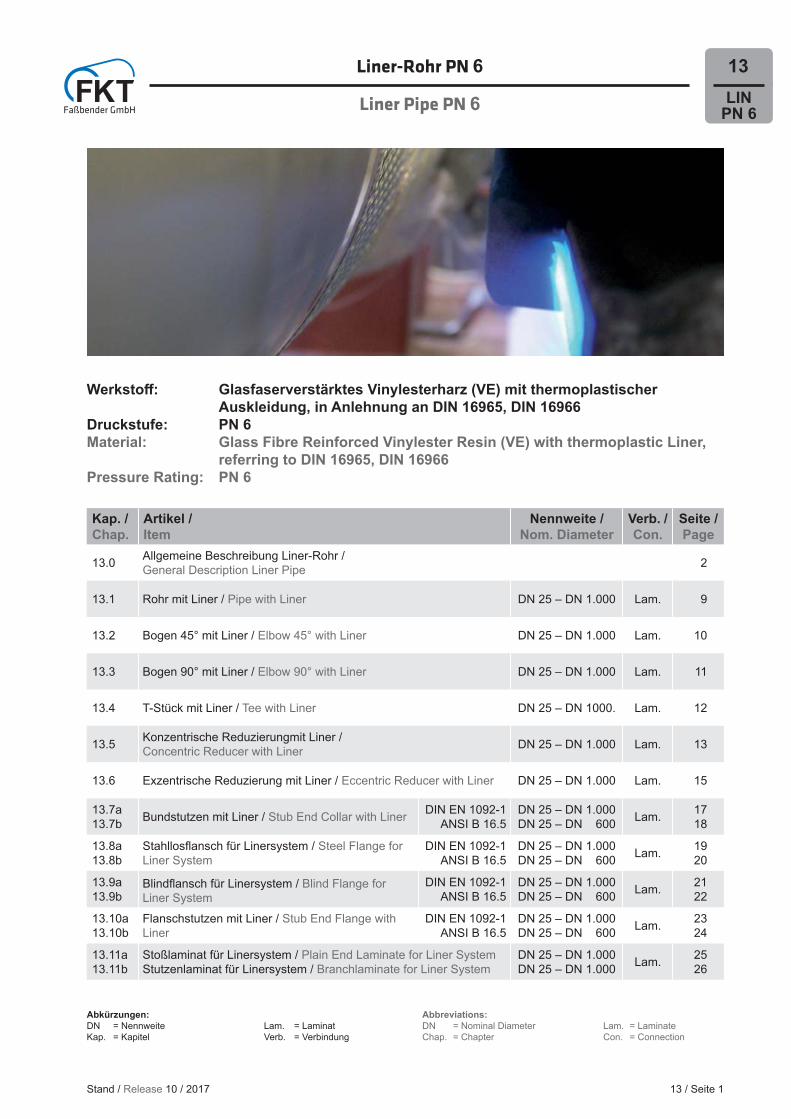
1 Besonders korrosionsfeste innere Auskleidung aus PP, PE, PVC oder PVDF (Liner).
2 Haftschicht
3 Traglaminat (GFK)
1 Especially corrosion-proof inner lining made of PE, PP, PVC, or PVDF (liner).
2 Bonding Layer.
3 Supporting Laminate (GRP)
Stand / Release 10 / 2017

Allgemeine Beschreibung Wickelrohre und Fittings DN 25 – 1.000General Description Filament Wound Pipes and Fittings
DN 25 – 1.000
FITTINGSBesides vinyl ester resign FKT’s Liner Fittings are made of glass fi bre mats and glass fabric. The fi t-tings are produced either in a fi lament-winding pro-cess or by applying the components manually. As well as the Liner Pipes, the fi ttings are lined with a pipe on the inside as a corrosion or abrasion pro-tective layer instead of the ordinary chemical pro-tective layer. This liner can optionally be made of PP, PE, PVC or PVDF. A bonding layer connects GRP and liner here as well.
The wide range of several kinds of fi ttings allows the installation of complex pipe systems. All stand-ard fi ttings that can be delivered are included in the charts of the following pages. Furthermore custom-ised fi ttings are available for special pipelines.
MATERIALGlass fi bre reinforced plastic (GRP) is a composite material, consisting of two diff erent components. Reinforcing fi bres made of textile glass possess excellent mechanical strength and combined with duroplastic resins they are used to ensure the pipe payload for thermoplastic lined pipes. The thermo-plastic liner that is used is optionally made of PP, PE, PVC or PVDF and acts as the protective layer of the pipe, because of its excellent chemical resist-ance and abrasion behavior.
FKT uses vinyl ester resin as matrix material. These remain liquid before and during the production pro-cess. The glass fi bres are impregnated with resin and are then applied onto the thermoplastic liner of pipes and fi ttings. After shaping, the composite material is cured by adding controlled temperature, which causes a chemical reaction.
In consequence of its duroplastic properties, the composite material GRP retains its shape even at elevated temperatures while its high mechanical strength is characteristic. These properties, togeth-er with optimum corrosion resistance, chemical re-sistance and low weight, allow GRP piping systems with thermoplastic liner to be used in many areas of application with associated long-term operational safety.
13 / Seite 3
LINPN 6
13.0
FITTINGSFKT-Liner-Formstücke werden aus Vinylesterharz und unter Einsatz von Glasmatten und Geweben hergestellt. Vorgegangen wird dabei entweder nach dem Wickelverfahren oder nach dem Aufl ege-verfahren per Hand. Wie die Liner-Rohre erhalten auch die Formstücke anstelle der normalen Che-mieschutzschicht auf der Innenseite eine Ausklei-dung durch einen Liner als Korrosions- bzw. Abrasi-onsschutzschicht. Dieser Liner kann wahlweise aus PP, PE, PVC oder PVDF bestehen. Auch hier ver-bindet eine Haftschicht GFK und Liner miteinander.
Die Vielzahl der verschiedenen Arten von Form-stücken ermöglicht eine Ausführung komplizierter Rohrsysteme. Alle lieferbaren Standardformstücke sind aus den folgenden Maßtabellen ersichtlich. Des Weiteren können für besondere Rohrverläufe auch Sonderformstücke gefertigt werden.
WERKSTOFFGFK ist ein Verbundwerkstoff , der sich aus zwei unterschiedlichen Komponenten zusammensetzt. Verstärkungsfasern aus Textilglas zeichnen sich durch ihre hohe mechanische Belastbarkeit aus und dienen in Verbindung mit den duroplastischen Harzsystemen bei thermoplastisch gelinerten Roh-ren dazu, die Tragfähigkeit des Rohres zu gewähr-leisten. Der zum Einsatz kommende thermoplasti-sche Liner auf der Innenseite, wahlweise aus PP, PE, PVC oder PVDF, agiert mit seiner hervorragen-den chemischen Beständigkeit und seinem guten Abrasionsverhalten als Schutzschicht des Rohres.
Als Matrixwerkstoff verwendet FKT Vinylesterharz-systeme. Diese sind vor und während der Verarbei-tung fl üssig. Die Glasfasern werden mit dem Harz getränkt und bei Rohren und Formstücken auf den thermoplastischen Liner aufgebracht. Nach der Formgebung härtet der Verbundwerkstoff unter Zu-gabe von Wärme durch chemische Reaktion aus.
Aufgrund seiner duroplastischen Eigenschaften ist der Verbundwerkstoff GFK auch bei hohen Tem-peraturen nicht mehr verformbar und zeichnet sich außerdem durch hohe mechanische Belastbar-keit aus. Berücksichtigt man zudem die optima-le Korrosions- und Chemikalienbeständigkeit bei gleichzeitig geringem Gewicht, eröff nen sich viel-seitige Einsatzgebiete für GFK-Rohrsysteme mit
Stand / Release 10 / 2017
Allgemeine Beschreibung Wickelrohre und Fittings DN 25 – 1.000General Description Filament Wound Pipes and Fittings
DN 25 – 1.000
Our material-oriented production is subject to strict quality control systems, according to the relevant DIN and EN standards in force. Continuous moni-toring of quality and compliance with offi cial stand-ards ensure approval of FKT pipe systems for many areas of application.
CONNECTING TECHNIQUESAn essential factor in evaluating plastic pipe sys-tems is the technology applied for connecting pipes and fi ttings with one another. Therefore FKT provides a wide range of tried and tested, materi-al-based options. The detail instructions “Process-ing Instructions for Liner Pipes” (Chapter 16) de-scribe preparations and handling of the connecting techniques.
WELDING-LAMINATION CONNECTION
Plain pipe ends and fi ttings are joined into a durably safe connection by welding and laminating in pre-fabrication or on site. At this the thermoplastic liners are bonded in a fi rst step using mirror welding, high-speed hot gas welding or hot gas torch welding, de-pending on the type of liner. Afterwards the gap in the supporting laminate, which emerges because of the necessary recesses at pipe and fi tting ends, is closed by applying vinyl ester resin, fi bers and mats in a lamination process.
FLANGE CONNECTION
In the case of complicated isometrics which may have to be frequently disassembled, connections are carried out using fl anges with bolt patterns in accordance with DIN or ANSI standards. An assort-ment of several fl anges made of GRP with PP, PE, PVC or PVDF liners and metal are available.
13 / Seite 4
LINPN 6
13.0
thermopolastischem Liner bei langzeitiger Betriebs-sicherheit.
Die werkstoff gerechte Fertigung, unter Berück-sichtigung der branchenspezifi schen DIN- und EN-Normen, unterliegt einem strengen Quali-tätssicherungssystem. Kontinuierliche, amtliche Qualitätsüberwachungen gewährleisten die Zulas-sungen von FKT-Rohrsystemen für zahlreiche An-wendungsbereiche.
VERBINDUNGSTECHNIKENEinen wesentlichen Faktor bei der Bewertung von Kunststoff -Rohrsystemen stellt die Verbindungs-technik der Rohre und Formstücke miteinander dar. FKT-Rohrsysteme bieten dafür ein weites Spekt-rum an bewährten, werkstoff gerechten Möglichkei-ten. Vorbereitung und Handhabung erfolgen nach der Detailanweisung „Verarbeitungsanleitung für Liner Rohre“ (Kapitel 16).
SCHWEISS-LAMINIERVERBINDUNG
Glatte Rohrenden und Formteile werden durch die Schweiß-Laminierverbindung in der Vorfertigung und auf der Baustelle langzeitig sicher zusammen-gefügt. Hierbei werden die thermoplastischen Liner je nach Linertyp zuerst mittels Spiegelschweißen, Warmgasziehschweißen oder Warmgasfächel-schweißen miteinander verbunden. Anschließend wird die Lücke des Traglaminats, die durch die not-wendigen Aussparungen an Rohr- und Formstü-ckenden entsteht, durch Laminierung aus Vinyles-terharz, Geweben und Mattenlagen geschlossen.
FLANSCHVERBINDUNG
Bei komplizierten Isometrien mit häufi gen Demon-tageerfordernissen werden lösbare Flanschverbin-dungen mit Anschlussmaßen nach DIN oder ANSI verwendet. Ein Sortiment von Fest- und Losfl an-schen aus GFK mit PP, PE, PVC und PVDF Linern und Metall stehen hierbei zur Verfügung.
Stand / Release 10 / 2017
Allgemeine Beschreibung Wickelrohre und Fittings DN 25 – 1.000General Description Filament Wound Pipes and Fittings
DN 25 – 1.000
13 / Seite 5
LINPN 6
13.0
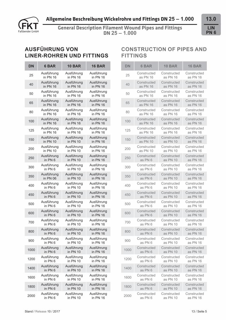
AUSFÜHRUNG VON LINER-ROHREN UND FITTINGS
CONSTRUCTION OF PIPES AND FITTINGS
DN 6 BAR 10 BAR 16 BAR
25 Constructed as PN 16
Constructed as PN 16
Constructed as PN 16
40 Constructed as PN 16
Constructed as PN 16
Constructed as PN 16
50 Constructed as PN 16
Constructed as PN 16
Constructed as PN 16
65 Constructed as PN 16
Constructed as PN 16
Constructed as PN 16
80 Constructed as PN 16
Constructed as PN 16
Constructed as PN 16
100 Constructed as PN 16
Constructed as PN 16
Constructed as PN 16
125 Constructed as PN 16
Constructed as PN 16
Constructed as PN 16
150 Constructed as PN 10
Constructed as PN 10
Constructed as PN 16
200 Constructed as PN 10
Constructed as PN 10
Constructed as PN 16
250 Constructed as PN 6
Constructed as PN 10
Constructed as PN 16
300 Constructed as PN 6
Constructed as PN 10
Constructed as PN 16
350 Constructed as PN 6
Constructed as PN 10
Constructed as PN 16
400 Constructed as PN 6
Constructed as PN 10
Constructed as PN 16
450 Constructed as PN 6
Constructed as PN 10
Constructed as PN 16
500 Constructed as PN 6
Constructed as PN 10
Constructed as PN 16
600 Constructed as PN 6
Constructed as PN 10
Constructed as PN 16
700 Constructed as PN 6
Constructed as PN 10
Constructed as PN 16
800 Constructed as PN 6
Constructed as PN 10
Constructed as PN 16
900 Constructed as PN 6
Constructed as PN 10
Constructed as PN 16
1000 Constructed as PN 6
Constructed as PN 10
Constructed as PN 16
1200 Constructed as PN 6
Constructed as PN 10
Constructed as PN 16
1400 Constructed as PN 6
Constructed as PN 10
Constructed as PN 16
1600 Constructed as PN 6
Constructed as PN 10
Constructed as PN 16
1800 Constructed as PN 6
Constructed as PN 10
Constructed as PN 16
2000 Constructed as PN 6
Constructed as PN 10
Constructed as PN 16
DN 6 BAR 10 BAR 16 BAR
25 Ausführung in PN 16
Ausführung in PN 16
Ausführung in PN 16
40 Ausführung in PN 16
Ausführung in PN 16
Ausführung in PN 16
50 Ausführung in PN 16
Ausführung in PN 16
Ausführung in PN 16
65 Ausführung in PN 16
Ausführung in PN 16
Ausführung in PN 16
80 Ausführung in PN 16
Ausführung in PN 16
Ausführung in PN 16
100 Ausführung in PN 16
Ausführung in PN 16
Ausführung in PN 16
125 Ausführung in PN 16
Ausführung in PN 16
Ausführung in PN 16
150 Ausführung in PN 10
Ausführung in PN 10
Ausführung in PN 16
200 Ausführung in PN 10
Ausführung in PN 10
Ausführung in PN 16
250 Ausführung in PN 6
Ausführung in PN 10
Ausführung in PN 16
300 Ausführung in PN 6
Ausführung in PN 10
Ausführung in PN 16
350 Ausführung in PN 06
Ausführung in PN 10
Ausführung in PN 16
400 Ausführung in PN 6
Ausführung in PN 10
Ausführung in PN 16
450 Ausführung in PN 6
Ausführung in PN 10
Ausführung in PN 16
500 Ausführung in PN 6
Ausführung in PN 10
Ausführung in PN 16
600 Ausführung in PN 6
Ausführung in PN 10
Ausführung in PN 16
700 Ausführung in PN 6
Ausführung in PN 10
Ausführung in PN 16
800 Ausführung in PN 6
Ausführung in PN 10
Ausführung in PN 16
900 Ausführung in PN 6
Ausführung in PN 10
Ausführung in PN 16
1000 Ausführung in PN 6
Ausführung in PN 10
Ausführung in PN 16
1200 Ausführung in PN 6
Ausführung in PN 10
Ausführung in PN 16
1400 Ausführung in PN 6
Ausführung in PN 10
Ausführung in PN 16
1600 Ausführung in PN 6
Ausführung in PN 10
Ausführung in PN 16
1800 Ausführung in PN 6
Ausführung in PN 10
Ausführung in PN 16
2000 Ausführung in PN 6
Ausführung in PN 10
Ausführung in PN 16
Stand / Release 10 / 2017
Allgemeine Beschreibung Wickelrohre und Fittings DN 25 – 1.000General Description Filament Wound Pipes and Fittings
DN 25 – 1.000
QUALITY CONTROLA wide range of pipe system products made of GRP, with or without thermoplastic liners, backed by solid engineering and assembly are the founda-tion to cope successfully with the technically and evermore challenging tasks of both today and to-morrow. FKT’s long-standing experience with glass fi bre reinforced plastics, the material-oriented pro-cessing and a comprehensive quality assurance system following DIN EN ISO 9001 ensure the pro-duction of high quality products.
Besides the testing methods following international standards e.g. DIN, EN and ASTM, company stand-ards which are based on those are used as well. Along with it go of course checks of raw material, monitoring of the production process and testing of the fi nished products. This ensures that no product can be released or supplied unless it meets FKT’s and the customer’s requirements.
Furthermore are these standard testing methods of great importance for construction and prepara-tion of technical specifi cations. Appropriate quality control of material and products executed by FKT off er both planning security and security in handling the products. It also guarantees the consistent high quality of the products.
13 / Seite 6
LINPN 6
13.0
QUALITÄTSSICHERUNGEine breite Produktpalette von Rohrsystemen aus GFK, mit und ohne thermoplastischen Linern, in Verbindung mit einem soliden Engineering und der Montage sind die Grundlage zur Bewältigung im-mer höherer technischer Erfordernisse in Gegen-wart und Zukunft. Die jahrelangen Erfahrungen der FKT mit glasfaserverstärkten Kunststoff en, die werkstoff gerechten Verarbeitungsmethoden und ein umfangreiches Qualitätssicherungssystem nach DIN EN ISO 9001 gewährleisten die Herstel-lung von hochwertigen Erzeugnissen.
Neben den Testmethoden nach internationalen Prüfnormen, wie DIN, EN und ASTM, fi nden auch an diese Prüfnormen angelehnte Werknormen Anwendung. Eine Kontrolle des Rohmaterials und eine Überwachung des Herstellungsprozesses ge-hören ebenso zum Standard wie eine Prüfung der fertigen Erzeugnisse. Somit kann ausgeschlossen werden, dass Produkte, die nicht den Anforderun-gen der FKT und deren Kunden entsprechen, frei-gegeben bzw. ausgeliefert werden.
Außerdem kommt solchen Standard-Testmethoden auch große Bedeutung bei der Konstruktion und Erstellung technischer Spezifi kationen zu. Entspre-chend von der FKT durchgeführte Qualitätskontrol-len an Werkstoff en und Erzeugnissen bieten zum einen Planungssicherheit und zum anderen Si-cherheit im Umgang mit den Produkten. Auch die gleichbleibend hohe Qualität kann somit gewähr-leistet werden.
Stand / Release 10 / 2017
Anmerkung:
Die auf den folgenden Seiten tabellarisch darge-stellten Produktdaten entsprechen der deutschen Schreibweise für Zahlen.
Die Produktmaße können abweichen, entsprechen aber grundsätzlich den Mindestanforderungen.
Note:
The product data listed in tabular form on the fol-lowing pages complies with the German notation of numbers.
Product dimensions may vary, but in general they meet the minimum requirements.
ZUSAMMENSETZUNG DER BESTELLNUMMERNWie aus den folgenden Kapitelabschnitten zu ersehen, sind die gelinerten Bauteile mit unterschiedlichen Formstückenden lieferbar:
• Glattes Ende• Festfl ansch• Bund-Losfl ansch
Die Bestellnummer für Bauteile mit glattem Ende entspricht jeweils der Artikelnummer auf der Katalogseite des Bauteils. Das XX dient hierbei als Platzhalter für den gewünschten Liner (PE/PP, PVC, PVDF).
Werden andere Formstückenden oder eine gemischte Variante gewünscht, ist die vorgegebene Artikelnum-mer am Ende mit entsprechenden Kürzeln zu versehen:
BS Bundstutzen, FF Flanschstutzen, L Laminat / glattes Ende
BSTA Bundstutzen nach ANSI, FFA Flanschstutzen nach ANSI
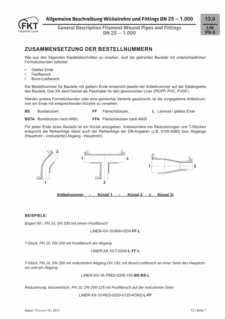
Für jedes Ende eines Bauteils ist ein Kürzel anzugeben. Insbesondere bei Reduzierungen und T-Stücken entspricht die Reihenfolge dabei auch der Reihenfolge der DN-Angaben (z.B. 0100-0080) bzw. Abgänge (Hauptrohr - (reduzierter) Abgang - Hauptrohr).
Artikelnummer - Kürzel 1 - Kürzel 2 (- Kürzel 3)
BEISPIELE:
Bogen 90°, PN 10, DN 200 mit einem Festfl ansch
LINER-XX-10-B90-0200-FF-L
T-Stück, PN 10, DN 200 mit Festfl ansch am Abgang
LINER-XX-10-T-0200-L-FF-L
T-Stück, PN 16, DN 200 mit reduziertem Abgang DN 150, mit Bund-Losfl ansch an einer Seite des Hauptroh-res und am Abgang
LINER-XX-16-TRED-0200-150-BS-BS-L
Reduzierung, konzentrisch, PN 10, DN 200-125 mit Festfl ansch auf der reduzierten Seite
LINER-XX-10-RED-0200-0125-KONZ-L-FF
Allgemeine Beschreibung Wickelrohre und Fittings DN 25 – 1.000General Description Filament Wound Pipes and Fittings
DN 25 – 1.000
13 / Seite 7
LINPN 6
13.0
Stand / Release 10 / 2017
3
2
1 2
2
1
1
Allgemeine Beschreibung Wickelrohre und Fittings DN 25 – 1.000General Description Filament Wound Pipes and Fittings
DN 25 – 1.000
13 / Seite 8
LINPN 6
13.0
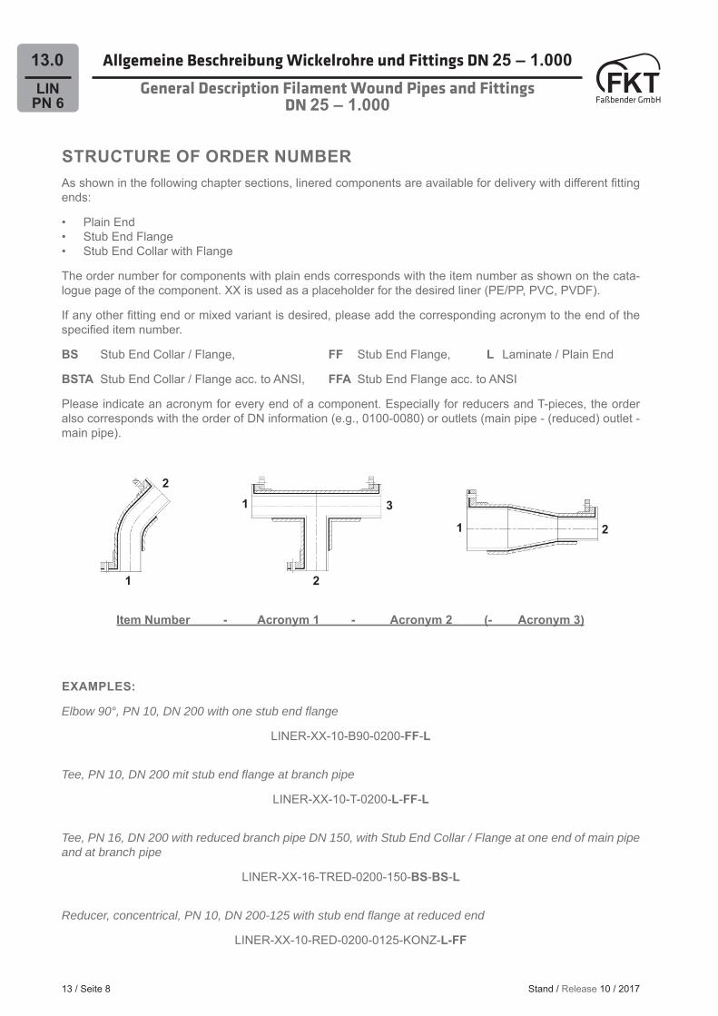
STRUCTURE OF ORDER NUMBERAs shown in the following chapter sections, linered components are available for delivery with diff erent fi tting ends:
• Plain End• Stub End Flange• Stub End Collar with Flange
The order number for components with plain ends corresponds with the item number as shown on the cata-logue page of the component. XX is used as a placeholder for the desired liner (PE/PP, PVC, PVDF).
If any other fi tting end or mixed variant is desired, please add the corresponding acronym to the end of the specifi ed item number.
BS Stub End Collar / Flange, FF Stub End Flange, L Laminate / Plain End
BSTA Stub End Collar / Flange acc. to ANSI, FFA Stub End Flange acc. to ANSI
Please indicate an acronym for every end of a component. Especially for reducers and T-pieces, the order also corresponds with the order of DN information (e.g., 0100-0080) or outlets (main pipe - (reduced) outlet - main pipe).
Item Number - Acronym 1 - Acronym 2 (- Acronym 3)
EXAMPLES:
Elbow 90°, PN 10, DN 200 with one stub end fl ange
LINER-XX-10-B90-0200-FF-L
Tee, PN 10, DN 200 mit stub end fl ange at branch pipe
LINER-XX-10-T-0200-L-FF-L
Tee, PN 16, DN 200 with reduced branch pipe DN 150, with Stub End Collar / Flange at one end of main pipe and at branch pipe
LINER-XX-16-TRED-0200-150-BS-BS-L
Reducer, concentrical, PN 10, DN 200-125 with stub end fl ange at reduced end
LINER-XX-10-RED-0200-0125-KONZ-L-FF
Stand / Release 10 / 2017
3
2
1 2
2
1
1
LINPN 6
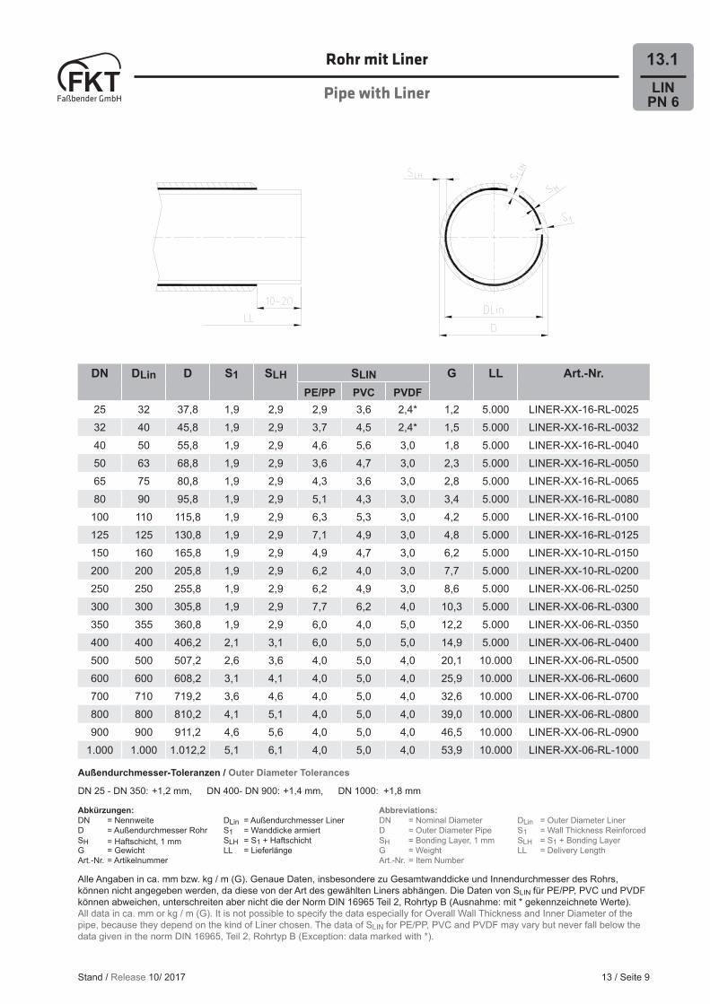
13.1Rohr mit Liner
Pipe with Liner
DN DLin D S1 SLH SLIN G LL Art.-Nr.PE/PP PVC PVDF
25 32 37,8 1,9 2,9 2,9 3,6 2,4* 1,2 5.000 LINER-XX-16-RL-002532 40 45,8 1,9 2,9 3,7 4,5 2,4* 1,5 5.000 LINER-XX-16-RL-003240 50 55,8 1,9 2,9 4,6 5,6 3,0 1,8 5.000 LINER-XX-16-RL-004050 63 68,8 1,9 2,9 3,6 4,7 3,0 2,3 5.000 LINER-XX-16-RL-005065 75 80,8 1,9 2,9 4,3 3,6 3,0 2,8 5.000 LINER-XX-16-RL-006580 90 95,8 1,9 2,9 5,1 4,3 3,0 3,4 5.000 LINER-XX-16-RL-0080
100 110 115,8 1,9 2,9 6,3 5,3 3,0 4,2 5.000 LINER-XX-16-RL-0100125 125 130,8 1,9 2,9 7,1 4,9 3,0 4,8 5.000 LINER-XX-16-RL-0125150 160 165,8 1,9 2,9 4,9 4,7 3,0 6,2 5.000 LINER-XX-10-RL-0150200 200 205,8 1,9 2,9 6,2 4,0 3,0 7,7 5.000 LINER-XX-10-RL-0200250 250 255,8 1,9 2,9 6,2 4,9 3,0 8,6 5.000 LINER-XX-06-RL-0250300 300 305,8 1,9 2,9 7,7 6,2 4,0 10,3 5.000 LINER-XX-06-RL-0300350 355 360,8 1,9 2,9 6,0 4,0 5,0 12,2 5.000 LINER-XX-06-RL-0350400 400 406,2 2,1 3,1 6,0 5,0 5,0 14,9 5.000 LINER-XX-06-RL-0400500 500 507,2 2,6 3,6 4,0 5,0 4,0 20,1 10.000 LINER-XX-06-RL-0500600 600 608,2 3,1 4,1 4,0 5,0 4,0 25,9 10.000 LINER-XX-06-RL-0600700 710 719,2 3,6 4,6 4,0 5,0 4,0 32,6 10.000 LINER-XX-06-RL-0700800 800 810,2 4,1 5,1 4,0 5,0 4,0 39,0 10.000 LINER-XX-06-RL-0800900 900 911,2 4,6 5,6 4,0 5,0 4,0 46,5 10.000 LINER-XX-06-RL-0900
1.000 1.000 1.012,2 5,1 6,1 4,0 5,0 4,0 53,9 10.000 LINER-XX-06-RL-1000
13 / Seite 9
Außendurchmesser-Toleranzen / Outer Diameter Tolerances
DN 25 - DN 350: +1,2 mm, DN 400- DN 900: +1,4 mm, DN 1000: +1,8 mm
Stand / Release 10/ 2017
Abbreviations:DN = Nominal Diameter DLin = Outer Diameter LinerD = Outer Diameter Pipe S1 = Wall Thickness ReinforcedSH = Bonding Layer, 1 mm SLH = S1 + Bonding LayerG = Weight LL = Delivery LengthArt.-Nr. = Item Number
Abkürzungen:DN = Nennweite DLin = Außendurchmesser LinerD = Außendurchmesser Rohr S1 = Wanddicke armiertSH = Haftschicht, 1 mm SLH = S1 + HaftschichtG = Gewicht LL = LieferlängeArt.-Nr. = Artikelnummer
Alle Angaben in ca. mm bzw. kg / m (G). Genaue Daten, insbesondere zu Gesamtwanddicke und Innendurchmesser des Rohrs, können nicht angegeben werden, da diese von der Art des gewählten Liners abhängen. Die Daten von SLIN für PE/PP, PVC und PVDF können abweichen, unterschreiten aber nicht die der Norm DIN 16965 Teil 2, Rohrtyp B (Ausnahme: mit * gekennzeichnete Werte).All data in ca. mm or kg / m (G). It is not possible to specify the data especially for Overall Wall Thickness and Inner Diameter of the pipe, because they depend on the kind of Liner chosen. The data of SLIN for PE/PP, PVC and PVDF may vary but never fall below the data given in the norm DIN 16965, Teil 2, Rohrtyp B (Exception: data marked with *).

LINPN 6
13.2 Bogen 45° mit Liner
Elbow 45° with Liner
DN DLin D S1 SLH r A PE/PP PVC PVDF Art.-Nr.25 32 37,8 1,9 2,9 32 70 2,9 3,6 2,4* LINER-XX-16-B45-002532 40 45,8 1,9 2,9 40 80 3,7 4,5 2,4* LINER-XX-16-B45-003240 50 55,8 1,9 2,9 50 90 4,6 5,6 3,0 LINER-XX-16-B45-004050 63 68,8 1,9 2,9 63 105 3,6 4,7 3,0 LINER-XX-16-B45-005065 75 80,8 1,9 2,9 75 85 4,3 3,6 3,0 LINER-XX-16-B45-006580 90 95,8 1,9 2,9 90 100 5,1 4,3 3,0 LINER-XX-16-B45-0080
100 110 115,8 1,9 2,9 110 115 6,3 5,3 3,0 LINER-XX-16-B45-0100125 125 130,8 1,9 2,9 125 135 7,1 4,9 3,0 LINER-XX-16-B45-0125150 160 165,8 1,9 2,9 160 150 4,9 4,7 3,0 LINER-XX-10-B45-0150200 200 205,8 1,9 2,9 200 190 6,2 4,0 3,0 LINER-XX-10-B45-0200250 250 255,8 1,9 2,9 250 225 6,2 4,9 3,0 LINER-XX-06-B45-0250300 300 305,8 1,9 2,9 300 260 7,7 6,2 4,0 LINER-XX-06-B45-0300350 355 360,8 1,9 2,9 355 290 6,0 4,0 5,0 LINER-XX-06-B45-0350400 400 406,2 2,1 3,1 400 325 6,0 5,0 5,0 LINER-XX-06-B45-0400500 500 507,2 2,6 3,6 500 390 4,0 5,0 4,0 LINER-XX-06-B45-0500600 600 608,2 3,1 4,1 600 430 4,0 5,0 4,0 LINER-XX-06-B45-0600700 710 719,2 3,6 4,6 710 490 4,0 5,0 4,0 LINER-XX-06-B45-0700800 800 810,2 4,1 5,1 800 545 4,0 5,0 4,0 LINER-XX-06-B45-0800900 900 911,2 4,6 5,6 900 605 4,0 5,0 4,0 LINER-XX-06-B45-0900
1.000 1.000 1.012,2 5,1 6,1 1.000 660 4,0 5,0 4,0 LINER-XX-06-B45-1000
13 / Seite 10
Abkürzungen:DN = Nennweite DLin = Außendurchmesser LinerD = Außendurchmesser Rohr S1 = Wanddicke armiertSLH = S1 + Haftschicht r = RadiusA = Achsmaß Art.-Nr. = Artikelnummer
Abbreviations:DN = Nominal Diameter DLin = Outer Diameter LinerD = Outer Diameter Pipe S1 = Wall Thickness ReinforcedSLH = S1 + Bonding Layer r = RadiusA = Axial Dimension Art.-Nr. = Item Number
Stand / Release 10 / 2017
Alle Angaben in ca. mm. Genaue Daten, insbes. zu Gesamtwanddicke und Innendurchmesser des Rohrs, können nicht angegeben werden, da diese von der Art des gewählten Liners abhängen. Die Daten von PE/PP, PVC und PVDF können abweichen, unterschrei-ten aber nicht die der Norm DIN 16965 Teil 2, Rohrtyp B (Ausnahme: mit * gekennzeichnete Werte). Die Haftschicht beträgt ca. 1 mm.All data in ca. mm. It is not possible to specify the data especially for Overall Wall Thickness and Inner Diameter of the pipe, because they depend on the kind of Liner chosen. The data of PE/PP, PVC and PVDF may vary but never fall below the data given in the norm DIN 16965, Teil 2, Rohrtyp B (Exception: data marked with *). The Bonding Layer amounts to ca. 1 mm.
Bestellnummer für verschiedene Formstückenden
siehe S. 7.
For order numbers of components
with various ends see p. 8.
LINPN 6
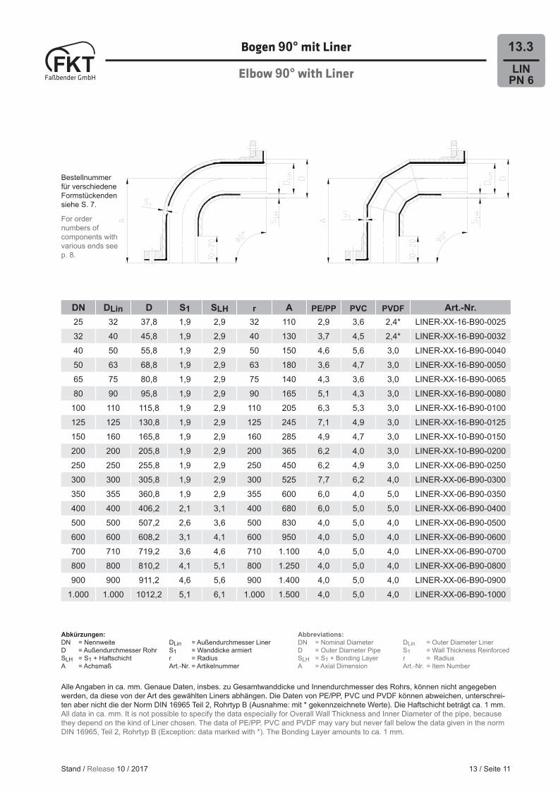
13.3Bogen 90° mit Liner
Elbow 90° with Liner
DN DLin D S1 SLH r A PE/PP PVC PVDF Art.-Nr.25 32 37,8 1,9 2,9 32 110 2,9 3,6 2,4* LINER-XX-16-B90-002532 40 45,8 1,9 2,9 40 130 3,7 4,5 2,4* LINER-XX-16-B90-003240 50 55,8 1,9 2,9 50 150 4,6 5,6 3,0 LINER-XX-16-B90-004050 63 68,8 1,9 2,9 63 180 3,6 4,7 3,0 LINER-XX-16-B90-005065 75 80,8 1,9 2,9 75 140 4,3 3,6 3,0 LINER-XX-16-B90-006580 90 95,8 1,9 2,9 90 165 5,1 4,3 3,0 LINER-XX-16-B90-0080
100 110 115,8 1,9 2,9 110 205 6,3 5,3 3,0 LINER-XX-16-B90-0100125 125 130,8 1,9 2,9 125 245 7,1 4,9 3,0 LINER-XX-16-B90-0125150 160 165,8 1,9 2,9 160 285 4,9 4,7 3,0 LINER-XX-10-B90-0150200 200 205,8 1,9 2,9 200 365 6,2 4,0 3,0 LINER-XX-10-B90-0200250 250 255,8 1,9 2,9 250 450 6,2 4,9 3,0 LINER-XX-06-B90-0250300 300 305,8 1,9 2,9 300 525 7,7 6,2 4,0 LINER-XX-06-B90-0300350 355 360,8 1,9 2,9 355 600 6,0 4,0 5,0 LINER-XX-06-B90-0350400 400 406,2 2,1 3,1 400 680 6,0 5,0 5,0 LINER-XX-06-B90-0400500 500 507,2 2,6 3,6 500 830 4,0 5,0 4,0 LINER-XX-06-B90-0500600 600 608,2 3,1 4,1 600 950 4,0 5,0 4,0 LINER-XX-06-B90-0600700 710 719,2 3,6 4,6 710 1.100 4,0 5,0 4,0 LINER-XX-06-B90-0700800 800 810,2 4,1 5,1 800 1.250 4,0 5,0 4,0 LINER-XX-06-B90-0800900 900 911,2 4,6 5,6 900 1.400 4,0 5,0 4,0 LINER-XX-06-B90-0900
1.000 1.000 1012,2 5,1 6,1 1.000 1.500 4,0 5,0 4,0 LINER-XX-06-B90-1000
13 / Seite 11
Abkürzungen:DN = Nennweite DLin = Außendurchmesser LinerD = Außendurchmesser Rohr S1 = Wanddicke armiertSLH = S1 + Haftschicht r = RadiusA = Achsmaß Art.-Nr. = Artikelnummer
Abbreviations:DN = Nominal Diameter DLin = Outer Diameter LinerD = Outer Diameter Pipe S1 = Wall Thickness ReinforcedSLH = S1 + Bonding Layer r = RadiusA = Axial Dimension Art.-Nr. = Item Number
Stand / Release 10 / 2017
Alle Angaben in ca. mm. Genaue Daten, insbes. zu Gesamtwanddicke und Innendurchmesser des Rohrs, können nicht angegeben werden, da diese von der Art des gewählten Liners abhängen. Die Daten von PE/PP, PVC und PVDF können abweichen, unterschrei-ten aber nicht die der Norm DIN 16965 Teil 2, Rohrtyp B (Ausnahme: mit * gekennzeichnete Werte). Die Haftschicht beträgt ca. 1 mm.All data in ca. mm. It is not possible to specify the data especially for Overall Wall Thickness and Inner Diameter of the pipe, because they depend on the kind of Liner chosen. The data of PE/PP, PVC and PVDF may vary but never fall below the data given in the norm DIN 16965, Teil 2, Rohrtyp B (Exception: data marked with *). The Bonding Layer amounts to ca. 1 mm.
Bestellnummer für verschiedene Formstückenden siehe S. 7.
For order numbers of components with various ends see p. 8.
LINPN 6
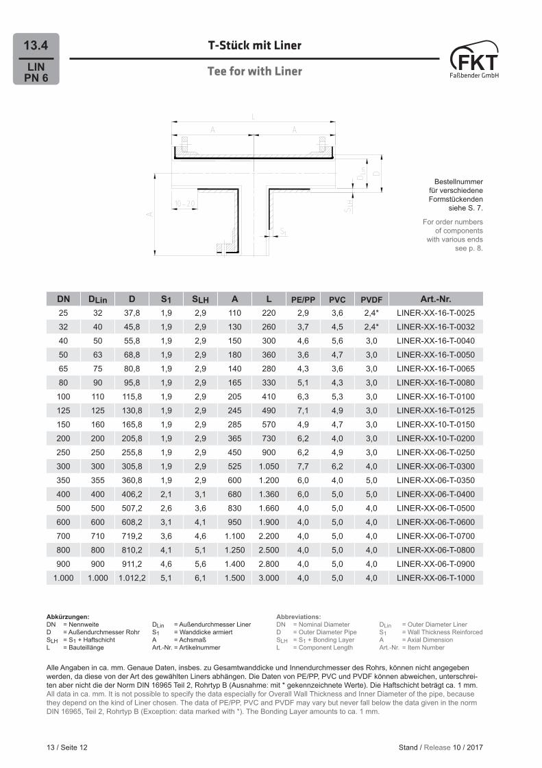
13.4 T-Stück mit Liner
Tee for with Liner
DN DLin D S1 SLH A L PE/PP PVC PVDF Art.-Nr.25 32 37,8 1,9 2,9 110 220 2,9 3,6 2,4* LINER-XX-16-T-002532 40 45,8 1,9 2,9 130 260 3,7 4,5 2,4* LINER-XX-16-T-003240 50 55,8 1,9 2,9 150 300 4,6 5,6 3,0 LINER-XX-16-T-004050 63 68,8 1,9 2,9 180 360 3,6 4,7 3,0 LINER-XX-16-T-005065 75 80,8 1,9 2,9 140 280 4,3 3,6 3,0 LINER-XX-16-T-006580 90 95,8 1,9 2,9 165 330 5,1 4,3 3,0 LINER-XX-16-T-0080
100 110 115,8 1,9 2,9 205 410 6,3 5,3 3,0 LINER-XX-16-T-0100125 125 130,8 1,9 2,9 245 490 7,1 4,9 3,0 LINER-XX-16-T-0125150 160 165,8 1,9 2,9 285 570 4,9 4,7 3,0 LINER-XX-10-T-0150200 200 205,8 1,9 2,9 365 730 6,2 4,0 3,0 LINER-XX-10-T-0200250 250 255,8 1,9 2,9 450 900 6,2 4,9 3,0 LINER-XX-06-T-0250300 300 305,8 1,9 2,9 525 1.050 7,7 6,2 4,0 LINER-XX-06-T-0300350 355 360,8 1,9 2,9 600 1.200 6,0 4,0 5,0 LINER-XX-06-T-0350400 400 406,2 2,1 3,1 680 1.360 6,0 5,0 5,0 LINER-XX-06-T-0400500 500 507,2 2,6 3,6 830 1.660 4,0 5,0 4,0 LINER-XX-06-T-0500600 600 608,2 3,1 4,1 950 1.900 4,0 5,0 4,0 LINER-XX-06-T-0600700 710 719,2 3,6 4,6 1.100 2.200 4,0 5,0 4,0 LINER-XX-06-T-0700800 800 810,2 4,1 5,1 1.250 2.500 4,0 5,0 4,0 LINER-XX-06-T-0800900 900 911,2 4,6 5,6 1.400 2.800 4,0 5,0 4,0 LINER-XX-06-T-0900
1.000 1.000 1.012,2 5,1 6,1 1.500 3.000 4,0 5,0 4,0 LINER-XX-06-T-1000
13 / Seite 12
Abkürzungen:DN = Nennweite DLin = Außendurchmesser LinerD = Außendurchmesser Rohr S1 = Wanddicke armiertSLH = S1 + Haftschicht A = AchsmaßL = Bauteillänge Art.-Nr. = Artikelnummer
Abbreviations:DN = Nominal Diameter DLin = Outer Diameter LinerD = Outer Diameter Pipe S1 = Wall Thickness ReinforcedSLH = S1 + Bonding Layer A = Axial DimensionL = Component Length Art.-Nr. = Item Number
Stand / Release 10 / 2017
Alle Angaben in ca. mm. Genaue Daten, insbes. zu Gesamtwanddicke und Innendurchmesser des Rohrs, können nicht angegeben werden, da diese von der Art des gewählten Liners abhängen. Die Daten von PE/PP, PVC und PVDF können abweichen, unterschrei-ten aber nicht die der Norm DIN 16965 Teil 2, Rohrtyp B (Ausnahme: mit * gekennzeichnete Werte). Die Haftschicht beträgt ca. 1 mm.All data in ca. mm. It is not possible to specify the data especially for Overall Wall Thickness and Inner Diameter of the pipe, because they depend on the kind of Liner chosen. The data of PE/PP, PVC and PVDF may vary but never fall below the data given in the norm DIN 16965, Teil 2, Rohrtyp B (Exception: data marked with *). The Bonding Layer amounts to ca. 1 mm.
Bestellnummer für verschiedene Formstückenden
siehe S. 7.
For order numbers of components
with various ends see p. 8.
LINPN 6
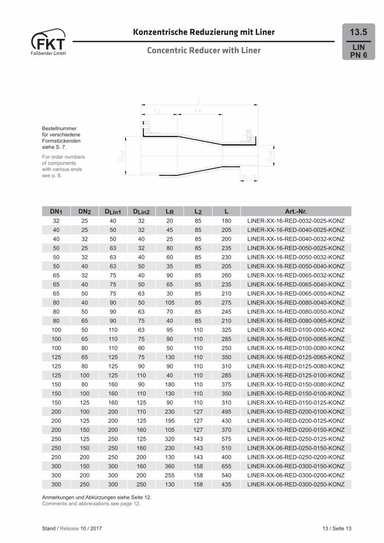
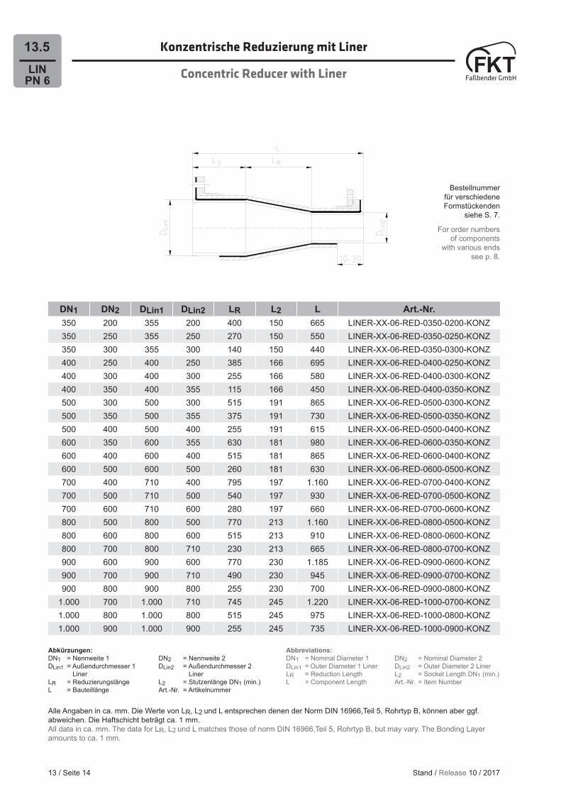
13.5Konzentrische Reduzierung mit Liner
Concentric Reducer with Liner
DN1 DN2 DLin1 DLin2 LR L2 L Art.-Nr.32 25 40 32 20 85 180 LINER-XX-16-RED-0032-0025-KONZ40 25 50 32 45 85 205 LINER-XX-16-RED-0040-0025-KONZ40 32 50 40 25 85 200 LINER-XX-16-RED-0040-0032-KONZ50 25 63 32 80 85 235 LINER-XX-16-RED-0050-0025-KONZ50 32 63 40 60 85 230 LINER-XX-16-RED-0050-0032-KONZ50 40 63 50 35 85 205 LINER-XX-16-RED-0050-0040-KONZ65 32 75 40 90 85 260 LINER-XX-16-RED-0065-0032-KONZ65 40 75 50 65 85 235 LINER-XX-16-RED-0065-0040-KONZ65 50 75 63 30 85 210 LINER-XX-16-RED-0065-0050-KONZ80 40 90 50 105 85 275 LINER-XX-16-RED-0080-0040-KONZ80 50 90 63 70 85 245 LINER-XX-16-RED-0080-0050-KONZ80 65 90 75 40 85 210 LINER-XX-16-RED-0080-0065-KONZ
100 50 110 63 95 110 325 LINER-XX-16-RED-0100-0050-KONZ100 65 110 75 90 110 285 LINER-XX-16-RED-0100-0065-KONZ100 80 110 90 50 110 250 LINER-XX-16-RED-0100-0080-KONZ125 65 125 75 130 110 350 LINER-XX-16-RED-0125-0065-KONZ125 80 125 90 90 110 310 LINER-XX-16-RED-0125-0080-KONZ125 100 125 110 40 110 285 LINER-XX-16-RED-0125-0100-KONZ150 80 160 90 180 110 375 LINER-XX-10-RED-0150-0080-KONZ150 100 160 110 130 110 350 LINER-XX-10-RED-0150-0100-KONZ150 125 160 125 90 110 310 LINER-XX-10-RED-0150-0125-KONZ200 100 200 110 230 127 495 LINER-XX-10-RED-0200-0100-KONZ200 125 200 125 195 127 430 LINER-XX-10-RED-0200-0125-KONZ200 150 200 160 105 127 370 LINER-XX-10-RED-0200-0150-KONZ250 125 250 125 320 143 575 LINER-XX-06-RED-0250-0125-KONZ250 150 250 160 230 143 510 LINER-XX-06-RED-0250-0150-KONZ250 200 250 200 130 143 400 LINER-XX-06-RED-0250-0200-KONZ300 150 300 160 360 158 655 LINER-XX-06-RED-0300-0150-KONZ300 200 300 200 255 158 540 LINER-XX-06-RED-0300-0200-KONZ300 250 300 250 130 158 435 LINER-XX-06-RED-0300-0250-KONZ
13 / Seite 13
Anmerkungen und Abkürzungen siehe Seite 12.Comments and abbreviations see page 12.
Stand / Release 10 / 2017
Bestellnummer für verschiedene Formstückenden siehe S. 7.
For order numbers of components with various ends see p. 8.
LINPN 6
13.5 Konzentrische Reduzierung mit Liner
Concentric Reducer with Liner
13 / Seite 14
DN1 DN2 DLin1 DLin2 LR L2 L Art.-Nr.350 200 355 200 400 150 665 LINER-XX-06-RED-0350-0200-KONZ350 250 355 250 270 150 550 LINER-XX-06-RED-0350-0250-KONZ350 300 355 300 140 150 440 LINER-XX-06-RED-0350-0300-KONZ400 250 400 250 385 166 695 LINER-XX-06-RED-0400-0250-KONZ400 300 400 300 255 166 580 LINER-XX-06-RED-0400-0300-KONZ400 350 400 355 115 166 450 LINER-XX-06-RED-0400-0350-KONZ500 300 500 300 515 191 865 LINER-XX-06-RED-0500-0300-KONZ500 350 500 355 375 191 730 LINER-XX-06-RED-0500-0350-KONZ500 400 500 400 255 191 615 LINER-XX-06-RED-0500-0400-KONZ600 350 600 355 630 181 980 LINER-XX-06-RED-0600-0350-KONZ600 400 600 400 515 181 865 LINER-XX-06-RED-0600-0400-KONZ600 500 600 500 260 181 630 LINER-XX-06-RED-0600-0500-KONZ700 400 710 400 795 197 1.160 LINER-XX-06-RED-0700-0400-KONZ700 500 710 500 540 197 930 LINER-XX-06-RED-0700-0500-KONZ700 600 710 600 280 197 660 LINER-XX-06-RED-0700-0600-KONZ800 500 800 500 770 213 1.160 LINER-XX-06-RED-0800-0500-KONZ800 600 800 600 515 213 910 LINER-XX-06-RED-0800-0600-KONZ800 700 800 710 230 213 665 LINER-XX-06-RED-0800-0700-KONZ900 600 900 600 770 230 1.185 LINER-XX-06-RED-0900-0600-KONZ900 700 900 710 490 230 945 LINER-XX-06-RED-0900-0700-KONZ900 800 900 800 255 230 700 LINER-XX-06-RED-0900-0800-KONZ
1.000 700 1.000 710 745 245 1.220 LINER-XX-06-RED-1000-0700-KONZ1.000 800 1.000 800 515 245 975 LINER-XX-06-RED-1000-0800-KONZ1.000 900 1.000 900 255 245 735 LINER-XX-06-RED-1000-0900-KONZ
Abkürzungen:DN1 = Nennweite 1 DN2 = Nennweite 2DLin1 = Außendurchmesser 1 DLin2 = Außendurchmesser 2 Liner LinerLR = Reduzierungslänge L2 = Stutzenlänge DN1 (min.)L = Bauteillänge Art.-Nr. = Artikelnummer
Abbreviations:DN1 = Nominal Diameter 1 DN2 = Nominal Diameter 2DLin1 = Outer Diameter 1 Liner DLin2 = Outer Diameter 2 LinerLR = Reduction Length L2 = Socket Length DN1 (min.)L = Component Length Art.-Nr. = Item Number
Stand / Release 10 / 2017
Alle Angaben in ca. mm. Die Werte von LR, L2 und L entsprechen denen der Norm DIN 16966,Teil 5, Rohrtyp B, können aber ggf.abweichen. Die Haftschicht beträgt ca. 1 mm.All data in ca. mm. The data for LR, L2 und L matches those of norm DIN 16966,Teil 5, Rohrtyp B, but may vary. The Bonding Layer amounts to ca. 1 mm.
Bestellnummer für verschiedene Formstückenden
siehe S. 7.
For order numbers of components
with various ends see p. 8.
LINPN 6
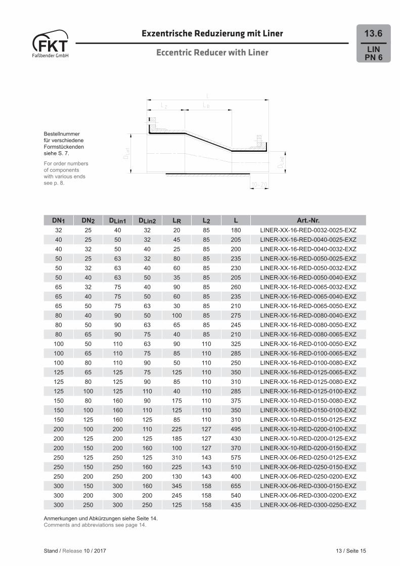
13.6Exzentrische Reduzierung mit Liner
Eccentric Reducer with Liner
13 / Seite 15
DN1 DN2 DLin1 DLin2 LR L2 L Art.-Nr.32 25 40 32 20 85 180 LINER-XX-16-RED-0032-0025-EXZ40 25 50 32 45 85 205 LINER-XX-16-RED-0040-0025-EXZ40 32 50 40 25 85 200 LINER-XX-16-RED-0040-0032-EXZ50 25 63 32 80 85 235 LINER-XX-16-RED-0050-0025-EXZ50 32 63 40 60 85 230 LINER-XX-16-RED-0050-0032-EXZ50 40 63 50 35 85 205 LINER-XX-16-RED-0050-0040-EXZ65 32 75 40 90 85 260 LINER-XX-16-RED-0065-0032-EXZ65 40 75 50 60 85 235 LINER-XX-16-RED-0065-0040-EXZ65 50 75 63 30 85 210 LINER-XX-16-RED-0065-0050-EXZ80 40 90 50 100 85 275 LINER-XX-16-RED-0080-0040-EXZ80 50 90 63 65 85 245 LINER-XX-16-RED-0080-0050-EXZ80 65 90 75 40 85 210 LINER-XX-16-RED-0080-0065-EXZ
100 50 110 63 90 110 325 LINER-XX-16-RED-0100-0050-EXZ100 65 110 75 85 110 285 LINER-XX-16-RED-0100-0065-EXZ100 80 110 90 50 110 250 LINER-XX-16-RED-0100-0080-EXZ125 65 125 75 125 110 350 LINER-XX-16-RED-0125-0065-EXZ125 80 125 90 85 110 310 LINER-XX-16-RED-0125-0080-EXZ125 100 125 110 40 110 285 LINER-XX-16-RED-0125-0100-EXZ150 80 160 90 175 110 375 LINER-XX-10-RED-0150-0080-EXZ150 100 160 110 125 110 350 LINER-XX-10-RED-0150-0100-EXZ150 125 160 125 85 110 310 LINER-XX-10-RED-0150-0125-EXZ200 100 200 110 225 127 495 LINER-XX-10-RED-0200-0100-EXZ200 125 200 125 185 127 430 LINER-XX-10-RED-0200-0125-EXZ200 150 200 160 100 127 370 LINER-XX-10-RED-0200-0150-EXZ250 125 250 125 310 143 575 LINER-XX-06-RED-0250-0125-EXZ250 150 250 160 225 143 510 LINER-XX-06-RED-0250-0150-EXZ250 200 250 200 130 143 400 LINER-XX-06-RED-0250-0200-EXZ300 150 300 160 345 158 655 LINER-XX-06-RED-0300-0150-EXZ300 200 300 200 245 158 540 LINER-XX-06-RED-0300-0200-EXZ300 250 300 250 125 158 435 LINER-XX-06-RED-0300-0250-EXZ
Anmerkungen und Abkürzungen siehe Seite 14.Comments and abbreviations see page 14.
Stand / Release 10 / 2017
Bestellnummer für verschiedene Formstückenden siehe S. 7.
For order numbers of components with various ends see p. 8.

LINPN 6
13.6 Exzentrische Reduzierung mit Liner
Eccentric Reducer with Liner
13 / Seite 16
DN1 DN2 DLin1 DLin2 LR L2 L Art.-Nr.350 200 355 200 385 150 665 LINER-XX-06-RED-0350-0200-EXZ350 250 355 250 260 150 550 LINER-XX-06-RED-0350-0250-EXZ350 300 355 300 135 150 440 LINER-XX-06-RED-0350-0300-EXZ400 250 400 250 370 166 695 LINER-XX-06-RED-0400-0250-EXZ400 300 400 300 245 166 580 LINER-XX-06-RED-0400-0300-EXZ400 350 400 355 110 166 450 LINER-XX-06-RED-0400-0350-EXZ500 300 500 300 495 191 865 LINER-XX-06-RED-0500-0300-EXZ500 350 500 355 360 191 730 LINER-XX-06-RED-0500-0350-EXZ500 400 500 400 245 191 615 LINER-XX-06-RED-0500-0400-EXZ600 350 600 355 605 181 980 LINER-XX-06-RED-0600-0350-EXZ600 400 600 400 495 181 865 LINER-XX-06-RED-0600-0400-EXZ600 500 600 500 245 181 630 LINER-XX-06-RED-0600-0500-EXZ700 400 710 400 765 197 1.160 LINER-XX-06-RED-0700-0400-EXZ700 500 710 500 520 197 930 LINER-XX-06-RED-0700-0500-EXZ700 600 710 600 270 197 660 LINER-XX-06-RED-0700-0600-EXZ800 500 800 500 740 213 1.160 LINER-XX-06-RED-0800-0500-EXZ800 600 800 600 495 213 910 LINER-XX-06-RED-0800-0600-EXZ800 700 800 710 220 213 665 LINER-XX-06-RED-0800-0700-EXZ900 600 900 600 740 230 1.185 LINER-XX-06-RED-0900-0600-EXZ900 700 900 710 470 230 945 LINER-XX-06-RED-0900-0700-EXZ900 800 900 800 245 230 700 LINER-XX-06-RED-0900-0800-EXZ
1.000 700 1.000 710 715 245 1.220 LINER-XX-06-RED-1000-0700-EXZ1.000 800 1.000 800 495 245 975 LINER-XX-06-RED-1000-0800-EXZ1.000 900 1.000 900 245 245 735 LINER-XX-06-RED-1000-0900-EXZ
Abkürzungen:DN1 = Nennweite 1 DN2 = Nennweite 2DLin1 = Außendurchmesser 1 DLin2 = Außendurchmesser 2 Liner LinerLR = Reduzierungslänge L2 = Stutzenlänge DN1 (min.)L = Bauteillänge Art.-Nr. = Artikelnummer
Abbreviations:DN1 = Nominal Diameter 1 DN2 = Nominal Diameter 2DLin1 = Outer Diameter 1 Liner DLin2 = Outer Diameter 2 LinerLR = Reduction Length L2 = Socket Length DN1 (min.)L = Component Length Art.-Nr. = Item Number
Stand / Release 10 / 2017
Alle Angaben in ca. mm. Die Werte von LR, L2 und L entsprechen denen der Norm DIN 16966,Teil 5, Rohrtyp B, können aber ggf.abweichen. Die Haftschicht beträgt ca. 1 mm.All data in ca. mm. The data for LR, L2 und L matches those of norm DIN 16966,Teil 5, Rohrtyp B, but may vary. The Bonding Layer amounts to ca. 1 mm.
Bestellnummer für verschiedene Formstückenden
siehe S. 7.
For order numbers of components
with various ends see p. 8.
LINPN 6
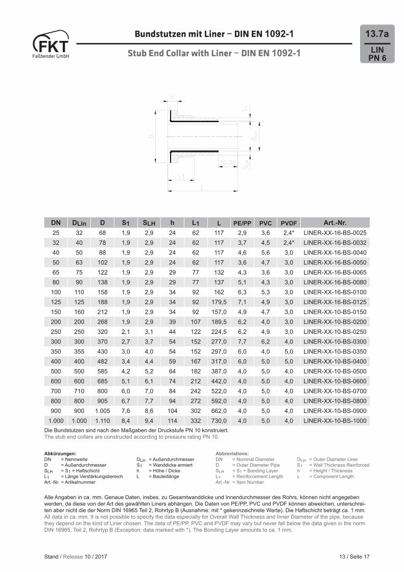
13.7aBundstutzen mit Liner − DIN EN 1092-1
Stub End Collar with Liner − DIN EN 1092-1
13 / Seite 17
DN DLin D S1 SLH h L1 L PE/PP PVC PVDF Art.-Nr.25 32 68 1,9 2,9 24 62 117 2,9 3,6 2,4* LINER-XX-16-BS-002532 40 78 1,9 2,9 24 62 117 3,7 4,5 2,4* LINER-XX-16-BS-003240 50 88 1,9 2,9 24 62 117 4,6 5,6 3,0 LINER-XX-16-BS-004050 63 102 1,9 2,9 24 62 117 3,6 4,7 3,0 LINER-XX-16-BS-005065 75 122 1,9 2,9 29 77 132 4,3 3,6 3,0 LINER-XX-16-BS-006580 90 138 1,9 2,9 29 77 137 5,1 4,3 3,0 LINER-XX-16-BS-0080
100 110 158 1,9 2,9 34 92 162 6,3 5,3 3,0 LINER-XX-16-BS-0100125 125 188 1,9 2,9 34 92 179,5 7,1 4,9 3,0 LINER-XX-16-BS-0125150 160 212 1,9 2,9 34 92 157,0 4,9 4,7 3,0 LINER-XX-10-BS-0150200 200 268 1,9 2,9 39 107 189,5 6,2 4,0 3,0 LINER-XX-10-BS-0200250 250 320 2,1 3,1 44 122 224,5 6,2 4,9 3,0 LINER-XX-10-BS-0250300 300 370 2,7 3,7 54 152 277,0 7,7 6,2 4,0 LINER-XX-10-BS-0300350 355 430 3,0 4,0 54 152 297,0 6,0 4,0 5,0 LINER-XX-10-BS-0350400 400 482 3,4 4,4 59 167 317,0 6,0 5,0 5,0 LINER-XX-10-BS-0400500 500 585 4,2 5,2 64 182 387,0 4,0 5,0 4,0 LINER-XX-10-BS-0500600 600 685 5,1 6,1 74 212 442,0 4,0 5,0 4,0 LINER-XX-10-BS-0600700 710 800 6,0 7,0 84 242 522,0 4,0 5,0 4,0 LINER-XX-10-BS-0700800 800 905 6,7 7,7 94 272 592,0 4,0 5,0 4,0 LINER-XX-10-BS-0800900 900 1.005 7,6 8,6 104 302 662,0 4,0 5,0 4,0 LINER-XX-10-BS-0900
1.000 1.000 1.110 8,4 9,4 114 332 730,0 4,0 5,0 4,0 LINER-XX-10-BS-1000Die Bundstutzen sind nach den Maßgaben der Druckstufe PN 10 konstruiert.The stub end collars are constructed according to pressure rating PN 10.
Abkürzungen:DN = Nennweite DLin = AußendurchmesserD = Außendurchmesser S1 = Wanddicke armiertSLH = S1 + Haftschicht h = Höhe / Dicke L1 = Länge Verstärkungsbereich L = Bauteillänge Art.-Nr. = Artikelnummer
Abbreviations:DN = Nominal Diameter DLin = Outer Diameter LinerD = Outer Diameter Pipe S1 = Wall Thickness ReinforcedSLH = S1 + Bonding Layer h = Height / ThicknessL1 = Reinforcement Length L = Component Length Art.-Nr. = Item Number
Stand / Release 10 / 2017
Alle Angaben in ca. mm. Genaue Daten, insbes. zu Gesamtwanddicke und Innendurchmesser des Rohrs, können nicht angegeben werden, da diese von der Art des gewählten Liners abhängen. Die Daten von PE/PP, PVC und PVDF können abweichen, unterschrei-ten aber nicht die der Norm DIN 16965 Teil 2, Rohrtyp B (Ausnahme: mit * gekennzeichnete Werte). Die Haftschicht beträgt ca. 1 mm.All data in ca. mm. It is not possible to specify the data especially for Overall Wall Thickness and Inner Diameter of the pipe, because they depend on the kind of Liner chosen. The data of PE/PP, PVC and PVDF may vary but never fall below the data given in the norm DIN 16965, Teil 2, Rohrtyp B (Exception: data marked with *). The Bonding Layer amounts to ca. 1 mm.

Bundstutzen mit Liner − ANSI B 16.5
Stub End Collar with Liner − ANSI B 16.5
13 / Seite 18
LINPN 6
13.7b
DN DLin D S1 SLH h L1 L PE/PP PVC PVDF Art.-Nr.25 32 68 1,9 2,9 24 62 117,0 2,9 3,6 2,4* LINER-XX-10-BSTA-002532 40 78 1,9 2,9 24 62 117,0 3,7 4,5 2,4* LINER-XX-10-BSTA-003240 50 88 1,9 2,9 24 62 117,0 4,6 5,6 3,0 LINER-XX-10-BSTA-004050 63 102 1,9 2,9 24 62 117,0 3,6 4,7 3,0 LINER-XX-10-BSTA-005065 75 122 1,9 2,9 29 77 132,0 4,3 3,6 3,0 LINER-XX-10-BSTA-006580 90 138 1,9 2,9 29 77 137,0 5,1 4,3 3,0 LINER-XX-10-BSTA-0080
100 110 158 1,9 2,9 34 92 162,0 6,3 5,3 3,0 LINER-XX-10-BSTA-0100125 125 188 1,9 2,9 34 92 179,5 7,1 4,9 3,0 LINER-XX-10-BSTA-0125150 160 212 1,9 2,9 34 92 157,0 4,9 4,7 3,0 LINER-XX-10-BSTA-0150200 200 268 1,9 2,9 39 107 189,5 6,2 4,0 3,0 LINER-XX-10-BSTA-0200250 250 320 2,1 3,1 44 122 224,5 6,2 4,9 3,0 LINER-XX-10-BSTA-0250300 300 370 2,7 3,7 54 152 277,0 7,7 6,2 4,0 LINER-XX-10-BSTA-0300350 355 430 3,0 4,0 54 152 297,0 6,0 4,0 5,0 LINER-XX-10-BSTA-0350400 400 482 3,4 4,4 59 167 317,0 6,0 5,0 5,0 LINER-XX-10-BSTA-0400500 500 585 4,2 5,2 64 182 387,0 4,0 5,0 4,0 LINER-XX-10-BSTA-0500600 600 685 5,1 6,1 74 212 442,0 4,0 5,0 4,0 LINER-XX-10-BSTA-0600
Die Bundstutzen sind nach den Maßgaben der Druckstufe PN 10 konstruiert.The stub end collars are constructed according to pressure rating PN 10.
Abkürzungen:DN = Nennweite DLin = AußendurchmesserD = Außendurchmesser S1 = Wanddicke armiertSLH = S1 + Haftschicht h = Höhe / Dicke L1 = Länge Verstärkungsbereich L = Bauteillänge Art.-Nr. = Artikelnummer
Abbreviations:DN = Nominal Diameter DLin = Outer Diameter LinerD = Outer Diameter Pipe S1 = Wall Thickness ReinforcedSLH = S1 + Bonding Layer h = Height / ThicknessL1 = Reinforcement Length L = Component Length Art.-Nr. = Item Number
Stand / Release 10 / 2017
Alle Angaben in ca. mm. Genaue Daten, insbes. zu Gesamtwanddicke und Innendurchmesser des Rohrs, können nicht angegeben werden, da diese von der Art des gewählten Liners abhängen. Die Daten von PE/PP, PVC und PVDF können abweichen, unterschrei-ten aber nicht die der Norm DIN 16965 Teil 2, Rohrtyp B (Ausnahme: mit * gekennzeichnete Werte). Die Haftschicht beträgt ca. 1 mm.All data in ca. mm. It is not possible to specify the data especially for Overall Wall Thickness and Inner Diameter of the pipe, because they depend on the kind of Liner chosen. The data of PE/PP, PVC and PVDF may vary but never fall below the data given in the norm DIN 16965, Teil 2, Rohrtyp B (Exception: data marked with *). The Bonding Layer amounts to ca. 1 mm.
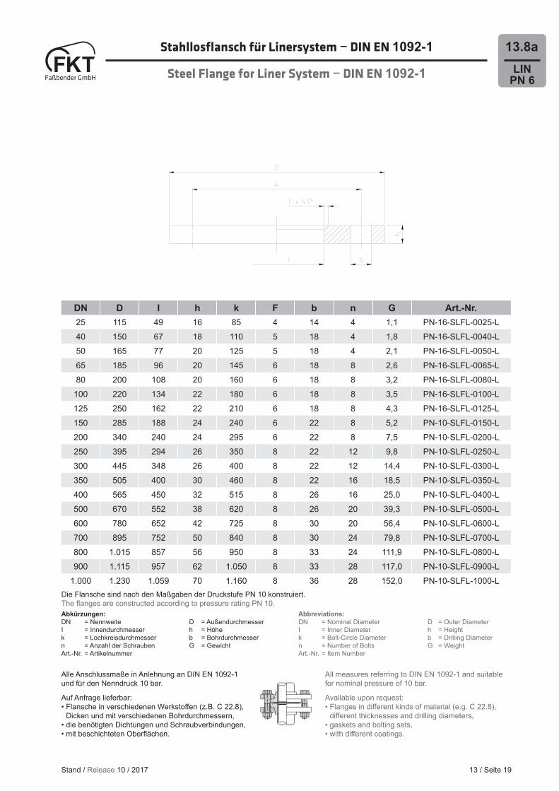
Stahllosfl ansch für Linersystem − DIN EN 1092-1
Steel Flange for Liner System − DIN EN 1092-1
13 / Seite 19
LINPN 6
13.8a
All measures referring to DIN EN 1092-1 and suitable for nominal pressure of 10 bar.
Available upon request:• Flanges in diff erent kinds of material (e.g. C 22.8), diff erent thicknesses and drilling diameters,• gaskets and bolting sets,• with diff erent coatings.
Abkürzungen:DN = Nennweite D = AußendurchmesserI = Innendurchmesser h = Höhek = Lochkreisdurchmesser b = Bohrdurchmessern = Anzahl der Schrauben G = GewichtArt.-Nr. = Artikelnummer
Abbreviations:DN = Nominal Diameter D = Outer DiameterI = Inner Diameter h = Heightk = Bolt-Circle Diameter b = Drilling Diametern = Number of Bolts G = WeightArt.-Nr. = Item Number
Alle Anschlussmaße in Anlehnung an DIN EN 1092-1 und für den Nenndruck 10 bar.
Auf Anfrage lieferbar:• Flansche in verschiedenen Werkstoff en (z.B. C 22.8), Dicken und mit verschiedenen Bohrdurchmessern, • die benötigten Dichtungen und Schraubverbindungen,• mit beschichteten Oberfl ächen.
DN D I h k F b n G Art.-Nr.25 115 49 16 85 4 14 4 1,1 PN-16-SLFL-0025-L40 150 67 18 110 5 18 4 1,8 PN-16-SLFL-0040-L50 165 77 20 125 5 18 4 2,1 PN-16-SLFL-0050-L65 185 96 20 145 6 18 8 2,6 PN-16-SLFL-0065-L80 200 108 20 160 6 18 8 3,2 PN-16-SLFL-0080-L
100 220 134 22 180 6 18 8 3,5 PN-16-SLFL-0100-L125 250 162 22 210 6 18 8 4,3 PN-16-SLFL-0125-L150 285 188 24 240 6 22 8 5,2 PN-10-SLFL-0150-L200 340 240 24 295 6 22 8 7,5 PN-10-SLFL-0200-L250 395 294 26 350 8 22 12 9,8 PN-10-SLFL-0250-L300 445 348 26 400 8 22 12 14,4 PN-10-SLFL-0300-L350 505 400 30 460 8 22 16 18,5 PN-10-SLFL-0350-L400 565 450 32 515 8 26 16 25,0 PN-10-SLFL-0400-L500 670 552 38 620 8 26 20 39,3 PN-10-SLFL-0500-L600 780 652 42 725 8 30 20 56,4 PN-10-SLFL-0600-L700 895 752 50 840 8 30 24 79,8 PN-10-SLFL-0700-L800 1.015 857 56 950 8 33 24 111,9 PN-10-SLFL-0800-L900 1.115 957 62 1.050 8 33 28 117,0 PN-10-SLFL-0900-L
1.000 1.230 1.059 70 1.160 8 36 28 152,0 PN-10-SLFL-1000-LDie Flansche sind nach den Maßgaben der Druckstufe PN 10 konstruiert.The fl anges are constructed according to pressure rating PN 10.
Stand / Release 10 / 2017
Stahllosfl ansch für Linersystem − ANSI B 16.5
Steel Flange for Liner System − ANSI B 16.5
13 / Seite 20
LINPN 6
13.8b
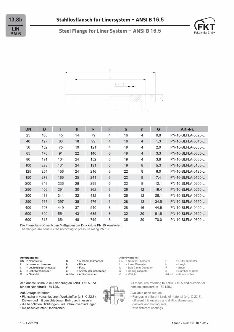
DN D I h k F b n G Art.-Nr.25 108 45 14 79 4 16 4 0,8 PN-10-SLFLA-0025-L40 127 63 18 99 4 16 4 1,3 PN-10-SLFLA-0040-L50 152 75 19 121 4 19 4 2,0 PN-10-SLFLA-0050-L65 178 91 22 140 6 19 4 3,3 PN-10-SLFLA-0065-L80 191 104 24 152 6 19 4 3,8 PN-10-SLFLA-0080-L
100 229 131 24 191 6 19 8 5,3 PN-10-SLFLA-0100-L125 254 156 24 216 6 22 8 6,0 PN-10-SLFLA-0125-L150 279 186 25 241 6 22 8 7,4 PN-10-SLFLA-0150-L200 343 236 28 299 6 22 8 12,1 PN-10-SLFLA-0200-L250 406 291 30 362 6 26 12 16,4 PN-10-SLFLA-0250-L300 483 341 32 432 6 26 12 26,1 PN-10-SLFLA-0300-L350 533 397 35 476 6 28 12 34,5 PN-10-SLFLA-0350-L400 597 449 37 540 8 28 16 44,6 PN-10-SLFLA-0400-L500 699 554 43 635 8 32 20 61,6 PN-10-SLFLA-0500-L600 813 654 48 749 8 35 20 70,0 PN-10-SLFLA-0600-L
Die Flansche sind nach den Maßgaben der Druckstufe PN 10 konstruiert.The fl anges are constructed according to pressure rating PN 10.
Abkürzungen:DN = Nennweite D = AußendurchmesserI = Innendurchmesser h = Höhek = Lochkreisdurchmesser F = Faseb = Bohrdurchmesser n = Anzahl der SchraubenG = Gewicht Art.-Nr. = Artikelnummer
Abbreviations:DN = Nominal Diameter D = Outer DiameterI = Inner Diameter h = Heightk = Bolt-Circle Diameter F = Bevelb = Drilling Diameter n = Number of BoltsG = Weight Art.-Nr. = Item Number
Alle Anschlussmaße in Anlehnung an ANSI B 16.5 und für den Nenndruck 150 LBS.
Auf Anfrage lieferbar:• Flansche in verschiedenen Werkstoff en (z.B. C 22.8), Dicken und mit verschiedenen Bohrdurchmessern, • die benötigten Dichtungen und Schraubverbindungen,• mit beschichteten Oberfl ächen.
All measures referring to ANSI B 16.5 and suitable for nominal pressure of 150 LBS.
Available upon request:• Flanges in diff erent kinds of material (e.g. C 22.8), diff erent thicknesses and drilling diameters,• gaskets and bolting sets,• with diff erent coatings.
Stand / Release 10 / 2017
LINPN 6
13.9a
13 / Seite 21
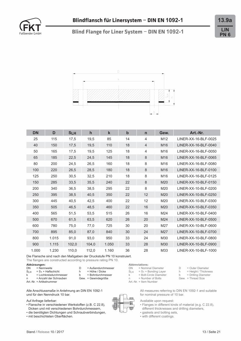
Blindfl ansch für Linersystem − DIN EN 1092-1
Blind Flange for Liner System − DIN EN 1092-1
Alle Anschlussmaße in Anlehnung an DIN EN 1092-1 und für den Nenndruck 10 bar.
Auf Anfrage lieferbar:• Flansche in verschiedenen Werkstoff en (z.B. C 22.8), Dicken und mit verschiedenen Bohrdurchmessern, • die benötigten Dichtungen und Schraubverbindungen,• mit beschichteten Oberfl ächen.
All measures referring to DIN EN 1092-1 and suitable for nominal pressure of 10 bar.
Available upon request:• Flanges in diff erent kinds of material (e.g. C 22.8), diff erent thicknesses and drilling diameters,• gaskets and bolting sets,• with diff erent coatings.
DN D SLH h k b n Gew. Art.-Nr.25 115 17,5 19,5 85 14 4 M12 LINER-XX-16-BLF-002540 150 17,5 19,5 110 18 4 M16 LINER-XX-16-BLF-004050 165 17,5 19,5 125 18 4 M16 LINER-XX-16-BLF-005065 185 22,5 24,5 145 18 8 M16 LINER-XX-16-BLF-006580 200 24,5 26,5 160 18 8 M16 LINER-XX-16-BLF-0080
100 220 26,5 28,5 180 18 8 M16 LINER-XX-16-BLF-0100125 250 30,5 32,5 210 18 8 M16 LINER-XX-16-BLF-0125150 285 33,5 35,5 240 22 8 M20 LINER-XX-10-BLF-0150200 340 36,5 38,5 295 22 8 M20 LINER-XX-10-BLF-0200250 395 38,5 40,5 350 22 12 M20 LINER-XX-10-BLF-0250300 445 40,5 42,5 400 22 12 M20 LINER-XX-10-BLF-0300350 505 46,5 48,5 460 22 16 M20 LINER-XX-10-BLF-0350400 565 51,5 53,5 515 26 16 M24 LINER-XX-10-BLF-0400500 670 61,5 63,5 620 26 20 M24 LINER-XX-10-BLF-0500600 780 75,0 77,0 725 30 20 M27 LINER-XX-10-BLF-0600700 895 85,0 87,0 840 30 24 M27 LINER-XX-10-BLF-0700800 1.015 91,0 93,0 950 33 24 M30 LINER-XX-10-BLF-0800900 1.115 102,0 104,0 1.050 33 28 M30 LINER-XX-10-BLF-0900
1.000 1.230 110,0 112,0 1.160 36 28 M33 LINER-XX-10-BLF-1000Die Flansche sind nach den Maßgaben der Druckstufe PN 10 konstruiert.The fl anges are constructed according to pressure rating PN 10.
Abbreviations:DN = Nominal Diameter D = Outer DiameterSLH = S1 + Bonding Layer h = Height / Thicknessk = Bolt-Circle Diameter b = Drilling Diameter n = Number of Bolts Gew. = Thread SizeArt.-Nr. = Item Number
Abkürzungen:DN = Nennweite D = AußendurchmesserSLH = S1 + Haftschicht h = Höhe / Dickek = Lochkreisdurchmesser b = Bohrdurchmessern = Anzahl der Schrauben Gew. = GewindegrößeArt.-Nr. = Artikelnummer
Stand / Release 10 / 2017
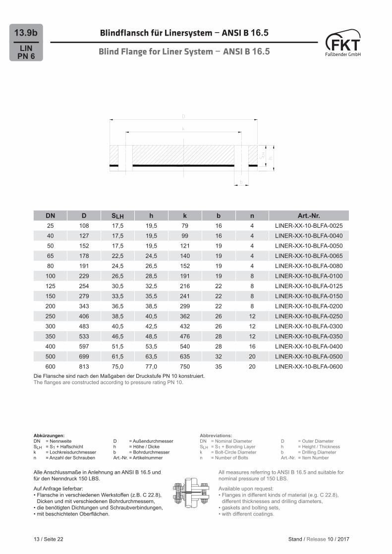
Blindfl ansch für Linersystem − ANSI B 16.5
Blind Flange for Liner System − ANSI B 16.5
13 / Seite 22
LINPN 6
13.9b
DN D SLH h k b n Art.-Nr.25 108 17,5 19,5 79 16 4 LINER-XX-10-BLFA-002540 127 17,5 19,5 99 16 4 LINER-XX-10-BLFA-004050 152 17,5 19,5 121 19 4 LINER-XX-10-BLFA-005065 178 22,5 24,5 140 19 4 LINER-XX-10-BLFA-006580 191 24,5 26,5 152 19 4 LINER-XX-10-BLFA-0080
100 229 26,5 28,5 191 19 8 LINER-XX-10-BLFA-0100125 254 30,5 32,5 216 22 8 LINER-XX-10-BLFA-0125150 279 33,5 35,5 241 22 8 LINER-XX-10-BLFA-0150200 343 36,5 38,5 299 22 8 LINER-XX-10-BLFA-0200250 406 38,5 40,5 362 26 12 LINER-XX-10-BLFA-0250300 483 40,5 42,5 432 26 12 LINER-XX-10-BLFA-0300350 533 46,5 48,5 476 28 12 LINER-XX-10-BLFA-0350400 597 51,5 53,5 540 28 16 LINER-XX-10-BLFA-0400500 699 61,5 63,5 635 32 20 LINER-XX-10-BLFA-0500600 813 75,0 77,0 750 35 20 LINER-XX-10-BLFA-0600
Die Flansche sind nach den Maßgaben der Druckstufe PN 10 konstruiert.The fl anges are constructed according to pressure rating PN 10.
Alle Anschlussmaße in Anlehnung an ANSI B 16.5 und für den Nenndruck 150 LBS.
Auf Anfrage lieferbar:• Flansche in verschiedenen Werkstoff en (z.B. C 22.8), Dicken und mit verschiedenen Bohrdurchmessern, • die benötigten Dichtungen und Schraubverbindungen,• mit beschichteten Oberfl ächen.
All measures referring to ANSI B 16.5 and suitable for nominal pressure of 150 LBS.
Available upon request:• Flanges in diff erent kinds of material (e.g. C 22.8), diff erent thicknesses and drilling diameters,• gaskets and bolting sets,• with diff erent coatings.
Abbreviations:DN = Nominal Diameter D = Outer DiameterSLH = S1 + Bonding Layer h = Height / Thicknessk = Bolt-Circle Diameter b = Drilling Diameter n = Number of Bolts Art.-Nr. = Item Number
Abkürzungen:DN = Nennweite D = AußendurchmesserSLH = S1 + Haftschicht h = Höhe / Dickek = Lochkreisdurchmesser b = Bohrdurchmessern = Anzahl der Schrauben Art.-Nr. = Artikelnummer
Stand / Release 10 / 2017
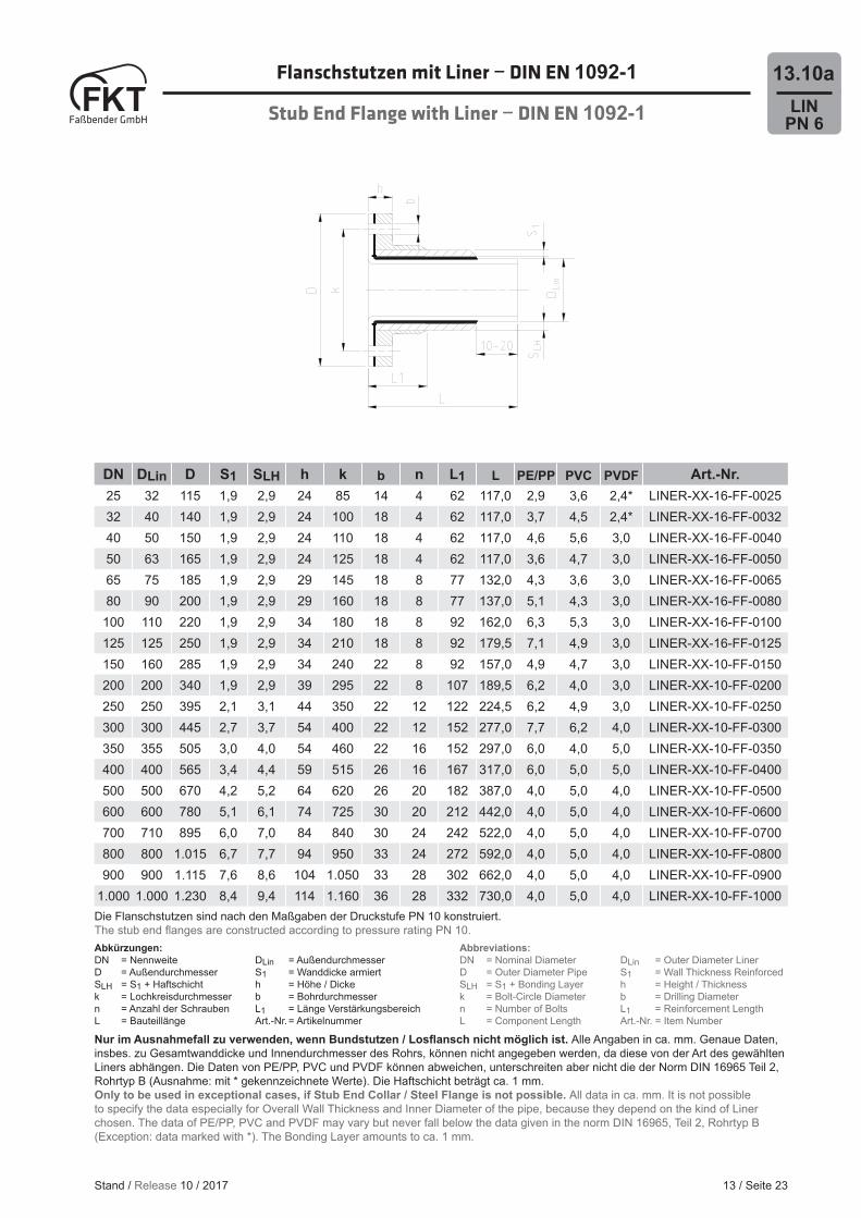
Flanschstutzen mit Liner − DIN EN 1092-1
Stub End Flange with Liner − DIN EN 1092-1
13 / Seite 23
LINPN 6
13.10a
DN DLin D S1 SLH h k b n L1 L PE/PP PVC PVDF Art.-Nr.25 32 115 1,9 2,9 24 85 14 4 62 117,0 2,9 3,6 2,4* LINER-XX-16-FF-002532 40 140 1,9 2,9 24 100 18 4 62 117,0 3,7 4,5 2,4* LINER-XX-16-FF-003240 50 150 1,9 2,9 24 110 18 4 62 117,0 4,6 5,6 3,0 LINER-XX-16-FF-004050 63 165 1,9 2,9 24 125 18 4 62 117,0 3,6 4,7 3,0 LINER-XX-16-FF-005065 75 185 1,9 2,9 29 145 18 8 77 132,0 4,3 3,6 3,0 LINER-XX-16-FF-006580 90 200 1,9 2,9 29 160 18 8 77 137,0 5,1 4,3 3,0 LINER-XX-16-FF-0080
100 110 220 1,9 2,9 34 180 18 8 92 162,0 6,3 5,3 3,0 LINER-XX-16-FF-0100125 125 250 1,9 2,9 34 210 18 8 92 179,5 7,1 4,9 3,0 LINER-XX-16-FF-0125150 160 285 1,9 2,9 34 240 22 8 92 157,0 4,9 4,7 3,0 LINER-XX-10-FF-0150200 200 340 1,9 2,9 39 295 22 8 107 189,5 6,2 4,0 3,0 LINER-XX-10-FF-0200250 250 395 2,1 3,1 44 350 22 12 122 224,5 6,2 4,9 3,0 LINER-XX-10-FF-0250300 300 445 2,7 3,7 54 400 22 12 152 277,0 7,7 6,2 4,0 LINER-XX-10-FF-0300350 355 505 3,0 4,0 54 460 22 16 152 297,0 6,0 4,0 5,0 LINER-XX-10-FF-0350400 400 565 3,4 4,4 59 515 26 16 167 317,0 6,0 5,0 5,0 LINER-XX-10-FF-0400500 500 670 4,2 5,2 64 620 26 20 182 387,0 4,0 5,0 4,0 LINER-XX-10-FF-0500600 600 780 5,1 6,1 74 725 30 20 212 442,0 4,0 5,0 4,0 LINER-XX-10-FF-0600700 710 895 6,0 7,0 84 840 30 24 242 522,0 4,0 5,0 4,0 LINER-XX-10-FF-0700800 800 1.015 6,7 7,7 94 950 33 24 272 592,0 4,0 5,0 4,0 LINER-XX-10-FF-0800900 900 1.115 7,6 8,6 104 1.050 33 28 302 662,0 4,0 5,0 4,0 LINER-XX-10-FF-0900
1.000 1.000 1.230 8,4 9,4 114 1.160 36 28 332 730,0 4,0 5,0 4,0 LINER-XX-10-FF-1000Die Flanschstutzen sind nach den Maßgaben der Druckstufe PN 10 konstruiert.The stub end fl anges are constructed according to pressure rating PN 10.
Abbreviations:DN = Nominal Diameter DLin = Outer Diameter LinerD = Outer Diameter Pipe S1 = Wall Thickness ReinforcedSLH = S1 + Bonding Layer h = Height / Thickness k = Bolt-Circle Diameter b = Drilling Diameter n = Number of Bolts L1 = Reinforcement LengthL = Component Length Art.-Nr. = Item Number
Abkürzungen:DN = Nennweite DLin = AußendurchmesserD = Außendurchmesser S1 = Wanddicke armiertSLH = S1 + Haftschicht h = Höhe / Dicke k = Lochkreisdurchmesser b = Bohrdurchmessern = Anzahl der Schrauben L1 = Länge VerstärkungsbereichL = Bauteillänge Art.-Nr. = Artikelnummer
Stand / Release 10 / 2017
Nur im Ausnahmefall zu verwenden, wenn Bundstutzen / Losfl ansch nicht möglich ist. Alle Angaben in ca. mm. Genaue Daten, insbes. zu Gesamtwanddicke und Innendurchmesser des Rohrs, können nicht angegeben werden, da diese von der Art des gewählten Liners abhängen. Die Daten von PE/PP, PVC und PVDF können abweichen, unterschreiten aber nicht die der Norm DIN 16965 Teil 2, Rohrtyp B (Ausnahme: mit * gekennzeichnete Werte). Die Haftschicht beträgt ca. 1 mm.Only to be used in exceptional cases, if Stub End Collar / Steel Flange is not possible. All data in ca. mm. It is not possible to specify the data especially for Overall Wall Thickness and Inner Diameter of the pipe, because they depend on the kind of Liner chosen. The data of PE/PP, PVC and PVDF may vary but never fall below the data given in the norm DIN 16965, Teil 2, Rohrtyp B (Exception: data marked with *). The Bonding Layer amounts to ca. 1 mm.

Flanschstutzen mit Liner − ANSI B 16.5
Stub End Flange with Liner − ANSI B 16.5
4 / Seite 24
LINPN 6
13.10b
DN DLin D S1 SLH h k b n L1 L PE/PP PVC PVDF Art.-Nr.25 32 108 1,9 2,9 24 79 16 4 62 117,0 2,9 3,6 2,4* LINER-XX-10-FFA-002540 50 127 1,9 2,9 24 99 16 4 62 117,0 4,6 5,6 3,0 LINER-XX-10-FFA-004050 63 152 1,9 2,9 24 121 19 4 62 117,0 3,6 4,7 3,0 LINER-XX-10-FFA-005065 75 178 1,9 2,9 29 140 19 4 77 132,0 4,3 3,6 3,0 LINER-XX-10-FFA-006580 90 191 1,9 2,9 29 152 19 4 77 137,0 5,1 4,3 3,0 LINER-XX-10-FFA-0080
100 110 229 1,9 2,9 34 191 19 8 92 162,0 6,3 5,3 3,0 LINER-XX-10-FFA-0100125 125 254 1,9 2,9 34 216 22 8 92 179,5 7,1 4,9 3,0 LINER-XX-10-FFA-0125150 160 279 1,9 2,9 34 241 22 8 92 157,0 4,9 4,7 3,0 LINER-XX-10-FFA-0150200 200 343 1,9 2,9 39 299 22 8 107 189,5 6,2 4,0 3,0 LINER-XX-10-FFA-0200250 250 406 2,1 3,1 44 362 26 12 122 224,5 6,2 4,9 3,0 LINER-XX-10-FFA-0250300 300 483 2,7 3,7 54 432 26 12 152 277,0 7,7 6,2 4,0 LINER-XX-10-FFA-0300350 355 533 3,0 4,0 54 476 28 12 152 297,0 6,0 4,0 5,0 LINER-XX-10-FFA-0350400 400 597 3,4 4,4 59 540 28 16 167 317,0 6,0 5,0 5,0 LINER-XX-10-FFA-0400500 500 699 4,2 5,2 64 635 32 20 182 387,0 4,0 5,0 4,0 LINER-XX-10-FFA-0500600 600 813 5,1 6,1 74 749 35 20 212 442,0 4,0 5,0 4,0 LINER-XX-10-FFA-0600
Die Flanschstutzen sind nach den Maßgaben der Druckstufe PN 10 konstruiert.The stub end fl anges are constructed according to pressure rating PN 10.
Abbreviations:DN = Nominal Diameter DLin = Outer Diameter LinerD = Outer Diameter Pipe S1 = Wall Thickness ReinforcedSLH = S1 + Bonding Layer h = Height / Thicknessk = Bolt-Circle Diameter b = Drilling Diametern = Number of Bolts L1 = Reinforcement LengthL = Component Length Art.-Nr. = Item Number
Abkürzungen:DN = Nennweite DLin = AußendurchmesserD = Außendurchmesser S1 = Wanddicke armiertSLH = S1 + Haftschicht h = Höhe / Dickek = Lochkreisdurchmesser b = Bohrdurchmessern = Anzahl der Schrauben L1 = Länge VerstärkungsbereichL = Bauteillänge Art.-Nr. = Artikelnummer
Stand / Release 10 / 2017
Nur im Ausnahmefall zu verwenden, wenn Bundstutzen / Losfl ansch nicht möglich ist. Alle Angaben in ca. mm. Genaue Daten, insbes. zu Gesamtwanddicke und Innendurchmesser des Rohrs, können nicht angegeben werden, da diese von der Art des gewählten Liners abhängen. Die Daten von PE/PP, PVC und PVDF können abweichen, unterschreiten aber nicht die der Norm DIN 16965 Teil 2, Rohrtyp B (Ausnahme: mit * gekennzeichnete Werte). Die Haftschicht beträgt ca. 1 mm.Only to be used in exceptional cases, if Stub End Collar / Steel Flange is not possible. All data in ca. mm. It is not possible to specify the data especially for Overall Wall Thickness and Inner Diameter of the pipe, because they depend on the kind of Liner chosen. The data of PE/PP, PVC and PVDF may vary but never fall below the data given in the norm DIN 16965, Teil 2, Rohrtyp B (Exception: data marked with *). The Bonding Layer amounts to ca. 1 mm.
LINPN 6
13.11a
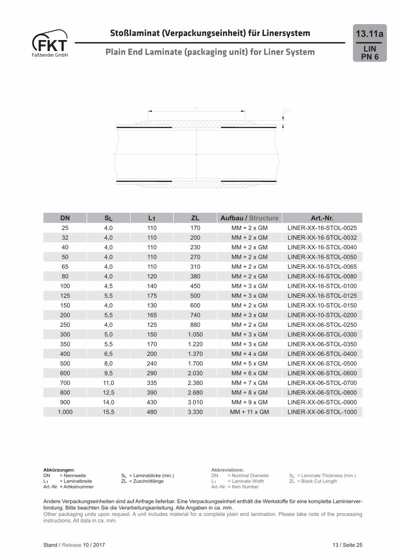
DN SL L1 ZL Aufbau / Structure Art.-Nr.25 4,0 110 170 MM + 2 x GM LINER-XX-16-STOL-002532 4,0 110 200 MM + 2 x GM LINER-XX-16-STOL-003240 4,0 110 230 MM + 2 x GM LINER-XX-16-STOL-004050 4,0 110 270 MM + 2 x GM LINER-XX-16-STOL-005065 4,0 110 310 MM + 2 x GM LINER-XX-16-STOL-006580 4,0 120 380 MM + 2 x GM LINER-XX-16-STOL-0080
100 4,5 140 450 MM + 3 x GM LINER-XX-16-STOL-0100125 5,5 175 500 MM + 3 x GM LINER-XX-16-STOL-0125150 4,0 130 600 MM + 2 x GM LINER-XX-10-STOL-0150200 5,5 165 740 MM + 3 x GM LINER-XX-10-STOL-0200250 4,0 125 880 MM + 2 x GM LINER-XX-06-STOL-0250300 5,0 150 1.050 MM + 3 x GM LINER-XX-06-STOL-0300350 5,5 170 1.220 MM + 3 x GM LINER-XX-06-STOL-0350400 6,5 200 1.370 MM + 4 x GM LINER-XX-06-STOL-0400500 8,0 240 1.700 MM + 5 x GM LINER-XX-06-STOL-0500600 9,5 290 2.030 MM + 6 x GM LINER-XX-06-STOL-0600700 11,0 335 2.380 MM + 7 x GM LINER-XX-06-STOL-0700800 12,5 390 2.680 MM + 8 x GM LINER-XX-06-STOL-0800900 14,0 430 3.010 MM + 9 x GM LINER-XX-06-STOL-0900
1.000 15,5 480 3.330 MM + 11 x GM LINER-XX-06-STOL-1000
13 / Seite 25
St0ßlaminat (Verpackungseinheit) für Linersystem
Plain End Laminate (packaging unit) for Liner System
Andere Verpackungseinheiten sind auf Anfrage lieferbar. Eine Verpackungseinheit enthält die Werkstoff e für eine komplette Laminierver-bindung. Bitte beachten Sie die Verarbeitungsanleitung. Alle Angaben in ca. mm.Other packaging units upon request. A unit includes material for a complete plain end lamination. Please take note of the processing instructions. All data in ca. mm.
Abkürzungen:DN = Nennweite SL = Laminatdicke (min.)L1 = Laminatbreite ZL = ZuschnittlängeArt.-Nr. = Artikelnummer
Abbreviations:DN = Nominal Diameter SL = Laminate Thickness (min.)L1 = Laminate Width ZL = Blank Cut LengthArt.-Nr. = Item Number
Stand / Release 10 / 2017
13 / Seite 26
LINPN 6
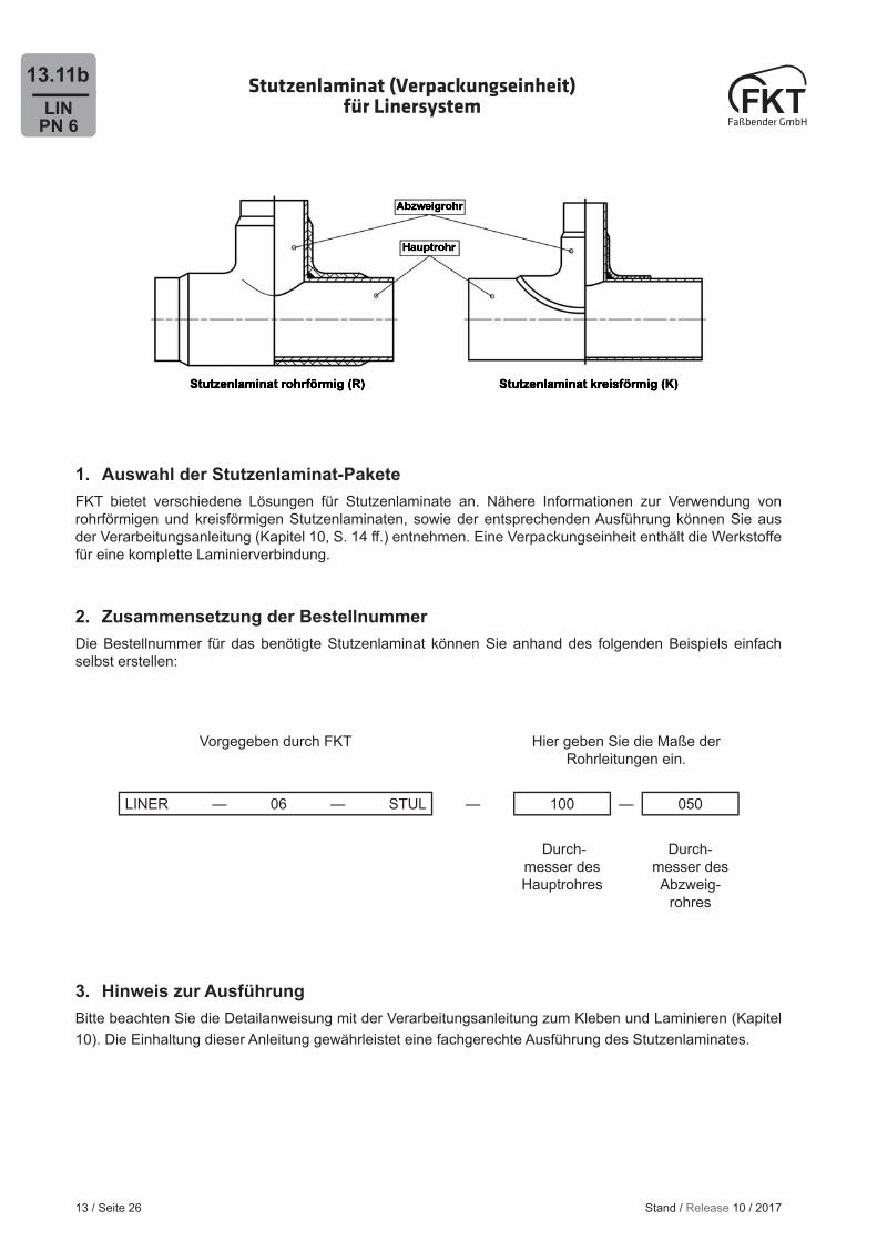
13.11b Stutzenlaminat (Verpackungseinheit) für Linersystem
1. Auswahl der Stutzenlaminat-PaketeFKT bietet verschiedene Lösungen für Stutzenlaminate an. Nähere Informationen zur Verwendung von rohrförmigen und kreisförmigen Stutzenlaminaten, sowie der entsprechenden Ausführung können Sie aus der Verarbeitungsanleitung (Kapitel 10, S. 14 ff .) entnehmen. Eine Verpackungseinheit enthält die Werkstoff e für eine komplette Laminierverbindung.
2. Zusammensetzung der BestellnummerDie Bestellnummer für das benötigte Stutzenlaminat können Sie anhand des folgenden Beispiels einfach selbst erstellen:
Vorgegeben durch FKT Hier geben Sie die Maße der Rohrleitungen ein.
LINER — 06 — STUL — 100 — 050
Durch-messer des Hauptrohres
Durch-messer des Abzweig-
rohres
3. Hinweis zur AusführungBitte beachten Sie die Detailanweisung mit der Verarbeitungsanleitung zum Kleben und Laminieren (Kapitel 10). Die Einhaltung dieser Anleitung gewährleistet eine fachgerechte Ausführung des Stutzenlaminates.
Stand / Release 10 / 2017
13 / Seite 27
LINPN 6
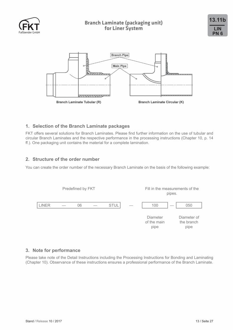
13.11bBranch Laminate (packaging unit) for Liner System
1. Selection of the Branch Laminate packagesFKT off ers several solutions for Branch Laminates. Please fi nd further information on the use of tubular and circular Branch Laminates and the respective performance in the processing instructions (Chapter 10, p. 14 ff .). One packaging unit contains the material for a complete lamination.
2. Structure of the order numberYou can create the order number of the necessary Branch Laminate on the basis of the following example:
Predefi ned by FKT Fill in the measurements of the pipes.
LINER — 06 — STUL — 100 — 050
Diameter of the main
pipe
Diameter of the branch
pipe
3. Note for performancePlease take note of the Detail Instructions including the Processing Instructions for Bonding and Laminating (Chapter 10). Observance of these instructions ensures a professional performance of the Branch Laminate.
Stand / Release 10 / 2017


![Data sheet Ball Valves JIP (PN 16, 25, 40) · Data sheet Ball valves Code No. DN [mm] WW PN 25 WW PN 40 DN [mm] FF PN 16 FF PN 25 FF PN 40 15 065N0100 15 - 065N0300 20 065N0105 20](https://img.dokumen.tips/doc/110x75/5e88b12f0d2e0736192ef20b/data-sheet-ball-valves-jip-pn-16-25-40-data-sheet-ball-valves-code-no-dn-mm.jpg)