Embed Size (px)
DESCRIPTION
IEEE
Citation preview

This article has been accepted for inclusion in a future issue of this journal. Content is final as presented, with the exception of pagination.
IEEE TRANSACTIONS ON CYBERNETICS 1
Linear Tracking for 3-D Medical Ultrasound ImagingQing-Hua Huang, Zhao Yang, Wei Hu, Lian-Wen Jin, Gang Wei, and Xuelong Li, Fellow, IEEE
Abstract—As the clinical application grows, there is a rapid tech-nical development of 3-D ultrasound imaging. Compared with 2-Dultrasound imaging, 3-D ultrasound imaging can provide improvedqualitative and quantitative information for various clinical appli-cations. In this paper, we proposed a novel tracking method fora freehand 3-D ultrasound imaging system with improved porta-bility, reduced degree of freedom, and cost. We designed a slidingtrack with a linear position sensor attached, and it transmittedpositional data via a wireless communication module based onBluetooth, resulting in a wireless spatial tracking modality. A tra-ditional 2-D ultrasound probe fixed to the position sensor on thesliding track was used to obtain real-time B-scans, and the posi-tions of the B-scans were simultaneously acquired when movingthe probe along the track in a freehand manner. In the experi-ments, the proposed method was applied to ultrasound phantomsand real human tissues. The results demonstrated that the new sys-tem outperformed a previously developed freehand system basedon a traditional six-degree-of-freedom spatial sensor in phantomand in vivo studies, indicating its merit in clinical applications forhuman tissues and organs.
Index Terms—Application system, one degree of freedom,volume reconstruction, wireless spatial tracking, 3-D ultrasound.
I. INTRODUCTION
THREE dimensional ultrasound imaging technology hasattracted growing attentions and been well developed be-
cause of its significant advantages in illustrating entire tissuesand providing quantitative analysis. In comparison with con-ventional 2-D ultrasound images, a 3-D ultrasound image al-lows viewing of an arbitrarily orientated image plane within thepatient and provides volume measurement of organs or lesions.In comparison with computerized tomography and magnetic
Manuscript received August 15, 2012; revised November 8, 2012; acceptedNovember 16, 2012. This work was supported by the National Basic ResearchProgram of China (973 Program) under Grant 2012CB316400, the NationalNatural Science Funds of China under Grant 61125106, Grant 61001181, Grant61075021, and Grant 91120302, and the Guangdong Natural Science Foun-dation (S2012010009885). This paper was recommended by Associate EditorS. H. Rubin of the former IEEE Transactions on Systems, Man and Cybernetics,Part C.
Q.-H. Huang, W. Hu, and G. Wei are with the Guangdong ProvincialKey Laboratory of Short-Range Wireless Detection and Communication andthe School of Electronic and Information Engineering, South China Univer-sity of Technology, Guangzhou 510006, China (e-mail: [email protected];[email protected]; [email protected]).
Z. Yang and L.-W. Jin are with the School of Electronic and Information En-gineering, South China University of Technology, Guangzhou 510006, China(e-mail: [email protected]; [email protected]).
X. Li is with the Center for Optical Imagery Analysis and Learning, StateKey Laboratory of Transient Optics and Photonics, Xi’an Institute of Opticsand Precision Mechanics, Chinese Academy of Sciences, Xi’an 710119, China(e-mail: [email protected]).
Color versions of one or more of the figures in this paper are available onlineat http://ieeexplore.ieee.org.
Digital Object Identifier 10.1109/TSMCC.2012.2229270
resonance imaging, 3-D ultrasound is a low-cost solution toobtaining 3-D medical images [3], [4].
As far as the scanning methods are concerned, 3-D ultrasoundimaging systems can be divided into three categories: mechan-ical scanners [2], [3], freehand techniques [14], and 2-D ar-rays [13]. Nowadays, for convenient purposes, some ultrasoundmachines are equipped with 3-D volumetric probes which makeuse of mechanical scanning or 2-D arrays embedded within adedicated housing. The 3-D probes can provide fast imaging ofhuman tissues. However, they are highly expensive, and theirfields of view and resolutions are relatively limited.
In contrast, 3-D freehand ultrasound imaging systems basedon conventional 2-D ultrasound machine acquire a series of 2-Dultrasound images (B-scans) and reconstruct them into a 3-Dvolume dataset using positional information corresponding tothe B-scans. Because the scanning is freely controlled by users,the data can be captured anywhere in human body and the fieldof view can be unlimitedly extended. Therefore, the freehandsystem is regarded as the most flexible and the cheapest solutionto 3-D ultrasound imaging [14].
In tracked freehand approaches, a position sensor is attachedto the probe to identify its gestures and motions during thescanning. According to a review [1], there have been varioussensors designed to capture gestures and motions of an ob-ject. In previously reported 3-D ultrasound systems, electro-magnetic and optical sensors are mostly often used to locate theprobe [6]–[9], [12]. These sensors offer six degrees of freedom(DoFs) and can measure the rotations and translations of theprobe. Hence, the freehand system allows users to arbitrarilymanipulate the probe during the raw data acquisition.
However, there is a tradeoff between the flexibility of dataacquisition and the accuracy of volume reconstruction for afreehand 3-D ultrasound system. It is obvious that the readingsof a position sensor are not absolutely accurate. Measurementerror is inevitable. The position sensor (e.g., an electromagneticsensor) is very sensitive to small flutters: A small jitter in theposition sensor reading would result in visible artifacts in images[10]. For a 6-DoF system, there are two kinds of error, i.e.,the translational error and the rotational error. Comparing withthe translational error, the rotational error would lead to muchlarger inaccuracies in the reconstruction process. In case theprobe is significantly rotated during a freehand scanning, largereconstruction error might occur. To this end, the movement ofthe probe with a uniform speed and little rotation was stronglyrecommended [11], and hence, a single sweep of the probe ina uniform manner was preferred rather than that in an arbitrarymanner [15].
Actually, a linear mechanical scanning device can make asingle sweep using a motor which drives the probe to move in afixed and linear path. The B-scans can be regularly collected andare visually parallel to each other. Because the scanning path
2168-2267/$31.00 © 2012 IEEE

This article has been accepted for inclusion in a future issue of this journal. Content is final as presented, with the exception of pagination.
2 IEEE TRANSACTIONS ON CYBERNETICS
Fig. 1. Illustration of the proposed 1-DoF 3-D ultrasound imaging system.
is limited to a straight line, the rotational error can be avoided,leading to a more accurate location of each B-scan. Nevertheless,the fixed path and probe motion decrease the flexibility of thescanning, and the additional driving device increases the costand inconvenience in real applications.
In order to achieve a good tradeoff between the freehandscanning and the mechanical scanning, we proposed a 1-DoFfreehand system for 3-D ultrasound imaging in this paper. The1-DoF system limited the motion of the probe in a single di-rection and avoided probe rotations. It looked like a mechanicalscanning system in which the probe was driven by a hand in-stead of a motor. Therefore, the flexibility of tracked freehand3-D imaging techniques partially remained. In addition, with-out using traditional spatial sensor (e.g., the electromagnetic oroptical sensor), its cost was further reduced and the whole sys-tem looked more portable because a wireless spatial trackingtechnique was adopted.
In Section II, the methods for development of the proposedsystem are introduced. Section III addresses the experimentsand illustrates the experimental results. Finally, conclusions aredrawn in Section IV.
II. METHODS
A. System design
As illustrated in Fig. 1, our 3-D ultrasound imaging sys-tem consisted of three parts: a conventional ultrasound machine(Sonix RP, Ultrasonix Medical Corporation, Richmond, BC,Canada) with a linear probe (L14-5/38) and a convex probe(C3-7/50) to generate B-scans, a common computer with avideo capture card (NI-IMAQ PCI-1405, National InstrumentsCorporation, Austin, TX) installed to collect images from theultrasound machine, and a linear sliding track with a positionsensor that provided positional readings.
As illustrated in Fig. 1, the sliding track was actually a digitalcaliper (Digital Scale Units, Model 812–103, Anyi InstrumentCo. Ltd., Shanghai, China) and the readings for distance mea-surement could be electronically measured and displayed in realtime. We designed a positioning module in which a microcon-
trol unit (MCU, Model PIC16F877A, Microchip TechnologyInc., Chandler, AZ) was used to read and process the digitaldistance measures from the caliper and a Bluetooth module wasembedded to wirelessly transmit the digital readings to a re-mote Bluetooth adaptor on a computer. The positioning modulewas fixedly attached to the measuring module of the caliper andcould be freely moved together with it. With a well-designedclip, the probe was fixed to the positioning module which couldbe regarded as a position sensor responsible for recording cur-rent positions of the caliper and transmitting the measures viathe Bluetooth module embedded.
To make sure that the position sensor could accurately recordthe real positions, we made 20 experiments. In each experiment,the measuring module of the caliper was randomly placed andthe distance measuring result was transferred to the positioningmodule. The positioning module then wirelessly transmitted thecurrent readings to the computer. The readings received by thecomputer were compared with that displayed in the caliper itself.In all of the experiments, we did not found any measurementdifference between the two types of readings, indicating thatthere was no measurement distortion caused by the positioningmodule.
The position module could be freely moved along the slidingtrack in the system. Hence, the DoF was 1. In our current de-sign, the outer dimensions of the sliding track was about 350 ×50 × H mm, where H was the height of the track and could beadjusted within a range of 50–200 mm in real applications.
When the probe was moved by an operator, the B-scans andthe positional measures could be simultaneously collected by thecomputer. The video capture card installed in the PC was usedto digitize and acquire real-time 2-D B-scans. The frame rate forraw image acquisition was 25 Hz. In our system, we acquired8-bit gray images to save the amount of storage. A Bluetooth linkwas established in the system to communicate between the po-sitioning module and the computer. A Bluetooth adapter shouldbe inserted into one of USB ports on the computer to receivethe positional information wirelessly transmitted from the po-sitioning module. Therefore, our system looked more portablethan those previously developed using 6-DoF position sensors.
A software system was developed using Visual C++ (Mi-crosoft Co. Ltd., Redmond, WA) in the computer and was re-sponsible for data acquisition, image processing, volume recon-struction, and visualization. Visualization Toolkits (VTK, Kit-ware Inc., Clifton Park, NY) were integrated into the softwaresystem for image display and volume rendering. The computerwas equipped with a Pentium dual-core CPU at 2.5 GHz and2-GB RAM. Fig. 2 demonstrates the work flow of the system.
B. Spatial Calibration
A conventional freehand 3-D ultrasound system should becalibrated to establish the correspondence between the B-scansand the spatial data. There are two types of calibration, i.e., thespatial calibration and temporal calibration. The spatial calibra-tion is required to determine the spatial relationship betweenthe B-scan image plane and the position sensor attached to theprobe. The temporal calibration is necessary for determining

This article has been accepted for inclusion in a future issue of this journal. Content is final as presented, with the exception of pagination.
HUANG et al.: LINEAR TRACKING FOR 3-D MEDICAL ULTRASOUND IMAGING 3
Fig. 2. Diagram of work flow for the 3-D ultrasound imaging system.
Fig. 3. Illustration of the spatial calibration experiment. P, S, T , and V denotethe coordinate system of B-scan image plane, the position sensor, the slidingtrack, and the volume dataset, respectively.
the temporal offset between the timestamps of the positionalinformation and the B-scans.
Because the proposed system was different from the freehand3-D system with 6 DoFs in terms of the scanning mode, it couldnot be calibrated using conventional methods. In this paper, wedesigned a new spatial calibration method with a newly designedphantom. As illustrated in Fig. 3, there were 5 × 5 small siliconballs each of which was supported by a stick on a flat table. Giventhat the width, height, and length of the table form a volumecoordinate system Cv , the 3-D locations of the balls could beprecisely measured. Using the proposed scanning protocol, theballs were fully scanned by the ultrasound probe. In the volumereconstruction, every pixel from the B-scans should be relocatedin the volume coordinate system. Thus, each pixel’s scan planelocation was first transformed into the coordinate system of theposition sensor attached to the sliding track and then into thevolume coordinate system. The overall mathematical expressionis as follows:
Cv (−→px) = vTt · tTs · sTp · −→px (1)
where −→px is the location of a pixel, sTp is the transformationmatrix from the coordinate system of the B-scan image plane Pto that of the position sensor S, tTs is the transformation matrixfrom the coordinate system of the position sensor S to that ofthe sliding track T, vTt is the transformation matrix from the
coordinate system of the sliding track T to that of the volume V,and Cv (−→px) is the location of the pixel in the volume coordinatesystem. The spatial calibration was employed to discover sTp
which is defined as follows:
sTp =
⎡⎢⎢⎢⎣
cos α cos β cos α sin β sin γ − sin α cos γ
sin α cos β sinα sin β sin γ + cos α cos γ
− sin β cos β sin γ
0 0
cos α sin β cos γ + sin α sin γ Xo
sin α sin β cos γ − cos α sin γ Y o
cos β cos γ Zo
0 1
⎤⎥⎥⎥⎦ . (2)
From Fig. 3, we assumed that the position sensor be fixedlyattached to the sliding track and should move along the Z-axis of T without any rotations and translations along the otherdirections. Thus, tTs could be simplified as
tTs =
⎡⎢⎢⎢⎣
1 0 0 0
0 1 0 0
0 0 1 Z (t)
0 0 0 1
⎤⎥⎥⎥⎦ (3)
where Z(t) is the distance between the origin of T and thelocation of the spatial sensor at time t.
It is observed that there are six unknown parameters (α, β,γ, Xo, Yo, and Zo) in sTp . Similarly, there are six unknownparameters in vTt . Considering the two scaling factors (i.e.,Sx and Sy) for the image resolution of the B-scan, there aretotally 12 parameters to be identified. Because the locations ofthe balls have been measured and known, we could build upa group of nonlinear homogeneous equations with respect tomanually marked locations of the balls on the B-scan imageplanes. To solve these equations, robust Levenberg–Marquardtalgorithm [19] which is an efficient method for the solution ofnonlinear problems was performed to estimate α, β, γ, Xo, Yo,and Zo in sTp .
C. Temporal Calibration
In the experiments for temporal calibration, we placed eightsilicon balls each of which was supported by a stick fixed at thebottom of a water tank, as illustrated in Fig. 4. The diameter ofeach ball was 1.5 mm. The positions corresponding to balls 1and 8 were recorded by the positioning module and denoted asPA and PB, respectively. We moved the probe to sweep all of theballs back and forth for several runs. In the collected images,those showing the centers of the balls were regarded as theimage markers and their timestamps were picked out as the timemarkers. At the same time, the positional data correspondingto the time markers were acquired and regarded as positionalmarkers.
The positional markers recorded during the temporal calibra-tion experiment were normalized to [0, 1] according to the range

This article has been accepted for inclusion in a future issue of this journal. Content is final as presented, with the exception of pagination.
4 IEEE TRANSACTIONS ON CYBERNETICS
Fig. 4. Illustration of the temporal calibration experiment.
Fig. 5. Temporal calibration results. (a) Real position and the position recordedin the software. (b) Root-mean-square errors between the two data streams.
of [PA, PB]. Similarly, the image markers were normalized to[0, 1] according to the range between balls 1 and 8.
The two normalized positions extracted from the image mark-ers and the positional markers, respectively, were then interpo-lated using a spline interpolation, as shown in Fig. 5(a). Timedelays between the two data streams could be observed. Thetime offset could be obtained by registering the two types ofnormalized positional measure. A search range of (−500 ms,500 ms) was used to find the optimal temporal shift correspond-ing to the lowest registration error. Fig. 5(b) shows the curve ofroot-mean-square error in registration of the two data streams
Fig. 6. Construction of the volume coordinates system.
shown in Fig. 5(a). Obviously, the temporal shift with theminimum root-mean-square error was the time delay betweenthe positional readings and the B-scans.
D. Volume Reconstruction and Analysis
Once the image sequence and corresponding positional datawere transferred into the computer simultaneously, the proce-dure of volume reconstruction was required to form 3-D ultra-sound images. With the reconstructed 3-D images, the functionsfor data visualization and analysis could be realized.
At the beginning of the volume reconstruction, a volumecoordinate system should be established. In our previously de-veloped freehand 3-D ultrasound system [12], we made use ofa 6-DoF spatial sensor, and the volume coordinate system wasdetermined by two predefined scanning positions. In contrast,the scanning method was simplified and the DoF was reduced to1 in this paper. As a result, the definition of volume coordinatesbecame straightforward. As illustrated in Fig. 6, the Z-axis wasparallel to the moving direction of the probe, and the Y -axiswas vertical to the ground. The origin of the volume coordinatesystem was set to be the left-top point of the first collected B-scan. The width (in X-axis) and height (in Y -axis) of the voxelarrays were set to be the same as those of the B-scan, and thelength along Z-axis was determined by the B-scan which wasthe farthest from the origin.
With the volume coordinate system, the pixels on B-scansshould be transformed from the coordinates of 2-D image planeto the coordinates of volume. The process is described by (1).Having transformed all pixels to the volume coordinate system,a data interpolation method should be performed to computethe values of the voxel array in the 3-D image based on thepixel values. In the past decade, various interpolation methodshave been proposed for volume reconstruction of 3-D ultra-sound [16]–[18]. Barry et al. [6] proposed to use a sphericalregion centered about each voxel and compute the weightedaverage of all pixels falling into the region. Their methodis called distance weighted interpolation. We previously pro-posed an improve method called squared distance weighted(SDW) interpolation [12] to preserve more image details, as

This article has been accepted for inclusion in a future issue of this journal. Content is final as presented, with the exception of pagination.
HUANG et al.: LINEAR TRACKING FOR 3-D MEDICAL ULTRASOUND IMAGING 5
Fig. 7. Display of three orthogonal slices of the fetus volume.
Fig. 8. Function for distance measurement based on three orthogonal views.
the following:
I(
�VC
)=
n∑k=0
WkI(
�V kP
)
n∑k=0
Wk
, Wk =1
(dk + α)2 (4)
where I(�VC ) is the intensity of the voxel at the volume coordi-nate �VC , n is the number of pixels falling within the predefinedspherical region centered about voxel �VC , I(�V k
P ) is the inten-sity of the kth pixel at the kth image coordinate �V k
P ,Wk is therelative weight for the kth pixel, dk is the distance from the kthvector transformed from �V k
P to the center of the voxel (�VC ),and α is a positive parameter for adjusting the effect of theinterpolation.
In this paper, we applied the SDW method to compute voxelvalues in reconstruction of volume data. The parameter α wasempirically set to be 0.3. The reconstructed volume was ren-dered using the VTK. In order to observe the internal structuresof the volume, we developed functions for reslicing volume,clipping volume, and generating orthogonal slices. Three or-thogonal slices of a fetus volume are shown in Fig. 7.
In addition, the functions for measurement of distance weredeveloped. From the orthogonal views, the distance betweenany two points could be easily measured, as illustrated in Fig. 8.The measured results were used for evaluation of the imagingaccuracy of the proposed system in this paper.
Fig. 9. Display of a reconstructed cylinder in the resolution phantom.
Fig. 10. Illustrations for measurement of distances between smaller targets inthe resolution phantom.
Fig. 11. New freehand scanning protocol for an in vivo test.
E. Experimental Methods
To assess the accuracy of the proposed 3-D ultrasound imag-ing system, we first conducted phantom experiments. An ul-trasound resolution phantom (Model 044, CIRS, Inc., Norfolk,VA) was employed. The phantom contained a number of copla-nar anechoic tubby cylindrical lesions with different lengthsand diameters. One of the longest cylinders was reconstructed,as shown in Fig. 9.We scanned the phantom for ten runs andobtained ten sets of volumetric data. With reference to the doc-umented dimensions, the imaging errors could be quantitativelymeasured. As illustrated in Fig. 9, the diameters in X- andY -directions, and the length in Z-direction could be measured

This article has been accepted for inclusion in a future issue of this journal. Content is final as presented, with the exception of pagination.
6 IEEE TRANSACTIONS ON CYBERNETICS
TABLE IQUANTITATIVE MEASUREMENT RESULTS OF THE DIMENSIONS ILLUSTRATED IN FIG. 7 AND THE DISTANCE ILLUSTRATED IN FIG. 8
within the reconstructed volume. The mean and standard de-viation (SD) of measurement errors were reported in the nextsection.
In addition to the cylindrical targets, we also made use of thesmaller targets to evaluate the accuracies of distance measure-ment based on the volumes produced by our system. As shownin Fig. 10, the distance between any of two adjacent targetscould be measured and compared with the documented value.The measurement errors indicated the imaging accuracy of thesystem.
Moreover, a fetus phantom (Model 068, CIRS, Inc., Norfolk,VA) was employed in the phantom study. Because the imagingdepth of the linear probe was too short to observe the entirefetus, it was scanned by the convex probe which was of lowcenter frequency and larger field of view. Its 3-D image couldbe used to qualitatively validate our system.
In our in vivo experiment, a young male subject (25 years old)was recruited. The subject’s forearm was immersed in a watertank and scanned by the linear probe, as illustrated in Fig. 11.The reconstructed volume could demonstrate the performanceof the proposed system in real applications. In order to betterillustrate the usefulness of the proposed system, it was alsocompared with a previously reported freehand system whichwas equipped with a 6-DoF spatial sensor (miniBird, Model500, Ascension, VT) [12] in the experiments.
III. RESULTS
Fig. 11 illustrates the process of data collection using theproposed system. The subject’s forearm immersed in a watertank was scanned. In the experiments, the sampling rate forimage acquisition was 21 Hz, and that for collecting positionaldata was 35 Hz. The region of interest of the B-scans was of480 × 450 pixels for the linear probe, and 280 × 240 pixelsfor the convex probe. The spatial calibration experiments wereconducted for ten runs. α, β, and γ were 0.03◦ ± 0.01◦, 0.06◦
± 0.03◦, and 0.04◦ ± 0.01◦, respectively, and Xo, Yo, and Zowere 4.32 ± 0.13 cm, 8.85 ± 0.09 cm, and 0.46 ± 0.06 cm,respectively. From the temporal calibration experiments, thetime delay of the positional data stream relative to the imagedata stream was 188.0 ± 2.2 ms.
Table I presents the quantitative measurement results us-ing two freehand 3-D ultrasound systems with 1-DoF and6-DoF position sensors, respectively. It can be obviously ob-served that the 1-DoF position sensor resulted in more accurate
Fig. 12. Reconstruction of a fetus phantom using (a) the proposed system and(b) a 6-DoF freehand 3-D ultrasound system.
measurement results, indicating a significantly improved imag-ing performance in comparison with traditional 6-DoF sensors.In another word, the imaging accuracy of the proposed systemwas improved by 0.46–2.14%. For the proposed system, theaverage error for the volume measurement of the cylindricallesion embedded in the resolution phantom was 1.06 ± 1.46%(mean ± SD).
Fig. 12 shows two typical 3-D images of the fetus phantomusing the proposed system and the 6-DoF system, respectively.In Fig. 12(a), the volume data consisting of 280 × 240 × 720voxels was reconstructed using 793 B-scans collected in twosweeps, and the computation time was 251 s. The head, limbs,and trunk of the fetus can be clearly observed. Although thereconstructed surfaces were not as smooth as the real one, theshape of each body part was almost identical to that of thephantom according to a qualitative evaluation, indicating goodperformance of the proposed system in 3-D ultrasound imaging.In Fig. 12(b), the volume data was computed based on the raw B-scans and spatial data generated by the 6-DoF sensor. However,the reconstruction errors appearing to be some distortions canbe obviously seen in the face, head, shoulder, and arm of thefetus.
Fig. 13 illustrates two volumes reconstructed from a part ofthe subject’s forearm based on the proposed system and the6-DoF system, respectively. In Fig. 13(a), there were totally 210B-scans collected, and the volume reconstruction took 49.3 s.The volume data consisted of 160 × 120 × 240 voxels. In com-parison with Fig. 13(a), the volume shown in Fig. 13(b) appearsless smooth, which was due to the relatively large reconstruction
This article has been accepted for inclusion in a future issue of this journal. Content is final as presented, with the exception of pagination.
HUANG et al.: LINEAR TRACKING FOR 3-D MEDICAL ULTRASOUND IMAGING 7
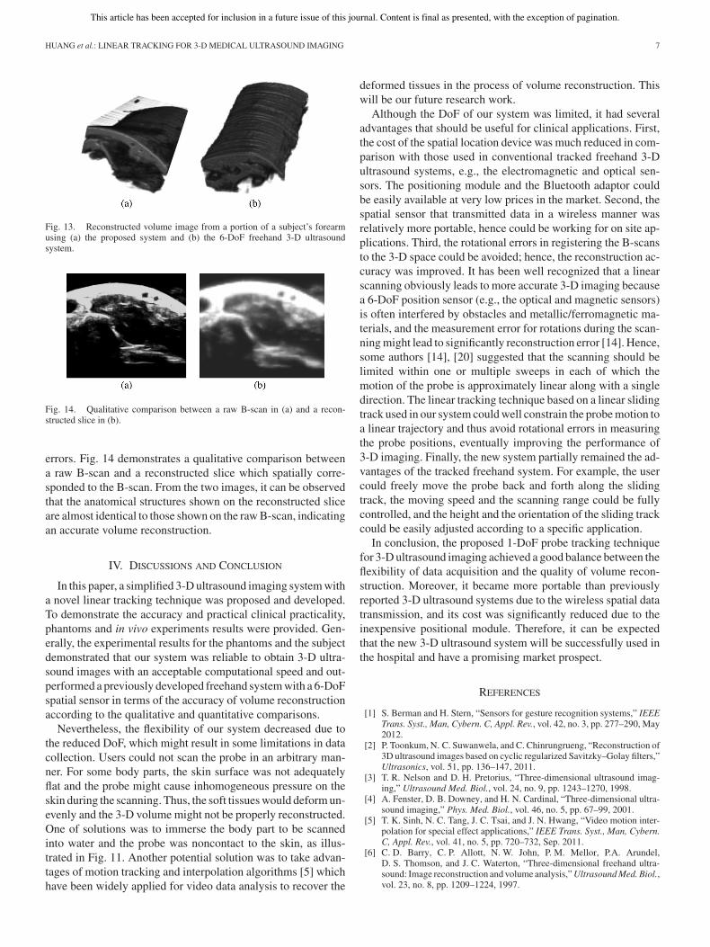
Fig. 13. Reconstructed volume image from a portion of a subject’s forearmusing (a) the proposed system and (b) the 6-DoF freehand 3-D ultrasoundsystem.
Fig. 14. Qualitative comparison between a raw B-scan in (a) and a recon-structed slice in (b).
errors. Fig. 14 demonstrates a qualitative comparison betweena raw B-scan and a reconstructed slice which spatially corre-sponded to the B-scan. From the two images, it can be observedthat the anatomical structures shown on the reconstructed sliceare almost identical to those shown on the raw B-scan, indicatingan accurate volume reconstruction.
IV. DISCUSSIONS AND CONCLUSION
In this paper, a simplified 3-D ultrasound imaging system witha novel linear tracking technique was proposed and developed.To demonstrate the accuracy and practical clinical practicality,phantoms and in vivo experiments results were provided. Gen-erally, the experimental results for the phantoms and the subjectdemonstrated that our system was reliable to obtain 3-D ultra-sound images with an acceptable computational speed and out-performed a previously developed freehand system with a 6-DoFspatial sensor in terms of the accuracy of volume reconstructionaccording to the qualitative and quantitative comparisons.
Nevertheless, the flexibility of our system decreased due tothe reduced DoF, which might result in some limitations in datacollection. Users could not scan the probe in an arbitrary man-ner. For some body parts, the skin surface was not adequatelyflat and the probe might cause inhomogeneous pressure on theskin during the scanning. Thus, the soft tissues would deform un-evenly and the 3-D volume might not be properly reconstructed.One of solutions was to immerse the body part to be scannedinto water and the probe was noncontact to the skin, as illus-trated in Fig. 11. Another potential solution was to take advan-tages of motion tracking and interpolation algorithms [5] whichhave been widely applied for video data analysis to recover the
deformed tissues in the process of volume reconstruction. Thiswill be our future research work.
Although the DoF of our system was limited, it had severaladvantages that should be useful for clinical applications. First,the cost of the spatial location device was much reduced in com-parison with those used in conventional tracked freehand 3-Dultrasound systems, e.g., the electromagnetic and optical sen-sors. The positioning module and the Bluetooth adaptor couldbe easily available at very low prices in the market. Second, thespatial sensor that transmitted data in a wireless manner wasrelatively more portable, hence could be working for on site ap-plications. Third, the rotational errors in registering the B-scansto the 3-D space could be avoided; hence, the reconstruction ac-curacy was improved. It has been well recognized that a linearscanning obviously leads to more accurate 3-D imaging becausea 6-DoF position sensor (e.g., the optical and magnetic sensors)is often interfered by obstacles and metallic/ferromagnetic ma-terials, and the measurement error for rotations during the scan-ning might lead to significantly reconstruction error [14]. Hence,some authors [14], [20] suggested that the scanning should belimited within one or multiple sweeps in each of which themotion of the probe is approximately linear along with a singledirection. The linear tracking technique based on a linear slidingtrack used in our system could well constrain the probe motion toa linear trajectory and thus avoid rotational errors in measuringthe probe positions, eventually improving the performance of3-D imaging. Finally, the new system partially remained the ad-vantages of the tracked freehand system. For example, the usercould freely move the probe back and forth along the slidingtrack, the moving speed and the scanning range could be fullycontrolled, and the height and the orientation of the sliding trackcould be easily adjusted according to a specific application.
In conclusion, the proposed 1-DoF probe tracking techniquefor 3-D ultrasound imaging achieved a good balance between theflexibility of data acquisition and the quality of volume recon-struction. Moreover, it became more portable than previouslyreported 3-D ultrasound systems due to the wireless spatial datatransmission, and its cost was significantly reduced due to theinexpensive positional module. Therefore, it can be expectedthat the new 3-D ultrasound system will be successfully used inthe hospital and have a promising market prospect.
REFERENCES
[1] S. Berman and H. Stern, “Sensors for gesture recognition systems,” IEEETrans. Syst., Man, Cybern. C, Appl. Rev., vol. 42, no. 3, pp. 277–290, May2012.
[2] P. Toonkum, N. C. Suwanwela, and C. Chinrungrueng, “Reconstruction of3D ultrasound images based on cyclic regularized Savitzky–Golay filters,”Ultrasonics, vol. 51, pp. 136–147, 2011.
[3] T. R. Nelson and D. H. Pretorius, “Three-dimensional ultrasound imag-ing,” Ultrasound Med. Biol., vol. 24, no. 9, pp. 1243–1270, 1998.
[4] A. Fenster, D. B. Downey, and H. N. Cardinal, “Three-dimensional ultra-sound imaging,” Phys. Med. Biol., vol. 46, no. 5, pp. 67–99, 2001.
[5] T. K. Sinh, N. C. Tang, J. C. Tsai, and J. N. Hwang, “Video motion inter-polation for special effect applications,” IEEE Trans. Syst., Man, Cybern.C, Appl. Rev., vol. 41, no. 5, pp. 720–732, Sep. 2011.
[6] C. D. Barry, C. P. Allott, N. W. John, P. M. Mellor, P.A. Arundel,D. S. Thomson, and J. C. Waterton, “Three-dimensional freehand ultra-sound: Image reconstruction and volume analysis,” Ultrasound Med. Biol.,vol. 23, no. 8, pp. 1209–1224, 1997.

This article has been accepted for inclusion in a future issue of this journal. Content is final as presented, with the exception of pagination.
8 IEEE TRANSACTIONS ON CYBERNETICS
[7] R. W. Prager, A. H. Gee, G. M. Treece, and L. Berman, “Freehand 3Dultrasound without voxels: Volume measurement and visualization usingthe Stradx system,” Ultrasonics, vol. 40, no. 1–8, pp. 109–115, 2002.
[8] A. Ali and R. Logeswaran, “A visual probe localization and calibrationsystem for cost-effective computer-aided 3D ultrasound,” Comput. Biol.Med., vol. 37, pp. 1141–1147, 2007.
[9] O. V. Solberg, F. Lindseth, L. E. Bø, S. Muller, J. B. L. Bakeng,G. A. Tangen, and T. A. N. Hernes, “3D ultrasound reconstruction al-gorithms from analog and digital data,” Ultrasonics, vol. 51, pp. 405–419,2011.
[10] R. J. Housden, A. H. Gee, G. M. Treece, and R. W. Prager, “Sensorlessreconstruction of unconstrained freehand 3D ultrasound data,” UltrasoundMed. Biol., vol. 33, no. 9, pp. 408–419, 2007.
[11] G. York and Y. M. Kim, “Ultrasound processing and computing: Reviewand future directions,” Annu. Rev. Biomed. Eng., vol. 1, pp. 559–588,1999.
[12] Q. H. Huang, Y. P. Zheng, M. H. Lu, and Z. R. Chi, “Development ofa Portable 3D Ultrasound imaging system for musculoskeletal tissues,”Ultrasonics, vol. 43, pp. 153–163, 2005.
[13] M. P. Fronheiser, S. F. Idriss, P. D. Wolf, and S. W. Smith, “Vibratinginterventional device detection using real-time 3-D color Doppler,” IEEETrans. Ultrason. Ferroelectr. Freq. Control, vol. 55, no. 6, pp. 1355–1362,Jun. 2008.
[14] A. H. Gee, R. W. Prager, G. M. Treece, and L. Berman, “Engineering afreehand 3D ultrasound system,” Pattern Recogn. Lett., vol. 24, no. 4/5,pp. 757–777, 2003.
[15] A. H. Gee, G. M. Treece, R. W. Prager, C. J. C. Cash, and L. Berman,“Rapid registration for wide field of view freehand three-dimensionalultrasound,” IEEE Trans. Med. Imaging, vol. 22, no. 11, pp. 1344–1357,Nov. 2003.
[16] R. N. Rohling, A. H. Gee, and L. Berman, “A comparison of freehandthree-dimensional ultrasound reconstruction techniques,” Med. ImageAnal., vol. 3, no. 4, pp. 339–359, 1999.
[17] Q. H. Huang and Y. P. Zheng, “Volume reconstruction of freehand three-dimensional ultrasound using median filters,” Ultrasonics, vol. 48, no. 3,pp. 182–192, 2008.
[18] Q. H. Huang, Y. P. Zheng, M. H. Lu, T. F. Wang, and S. P. Chen, “Newadaptive interpolation algorithm for 3D ultrasound imaging with specklereduction and edge preservation,” Comput. Med. Imaging Graph., vol. 33,no. 2, pp. 100–110, 2009.
[19] R. W. Prager, R. N. Rohling, A. H. Gee, and L. Berman, “Rapid calibra-tion for 3-D freehand ultrasound,” Ultrasound Med. Biol., vol. 24, no. 6,pp. 855–869, 1998.
[20] Q. H. Huang and Y.P. Zheng, “A new scanning approach for limb extremi-ties using a water bag in freehand 3-D ultrasound,” Ultrasound Med. Biol.,vol. 31, no. 4, pp. 575–583, 2005.
Qing-Hua Huang received the B.E. and M.E.degrees in automatic control and pattern recognition,both from the University of Science and Technol-ogy of China, Hefei, China, in 1999 and 2002, re-spectively, and the Ph.D. degree in biomedical engi-neering from the Hong Kong Polytechnic University,Hong Kong, in 2007.
Since 2008, he has been an Associate Profes-sor with the School of Electronic and InformationEngineering, South China University of Technology,Guangzhou, China. His research interests include ul-
trasonic imaging, medical image analysis, bioinformatics, intelligent computa-tion, and its applications.
Zhao Yang received the B.E. degree in communi-cation engineering from Hubei University, Wuhan,China, in 2008. He joined the School of Electronicand Information Engineering, South China Univer-sity of Technology, Guangzhou, China, as a Mas-ter’s student in 2009 and is currently working towardthe Ph.D. degree in machine learning and computervision.
Wei Hu received the B.E. degree in electronics andinformation engineering from Jiangnan University,Wuxi, China, in 2010. He is currently working towardthe Master’s degree with the School of Electronic andInformation Engineering, South China University ofTechnology, Guangzhou, China.
His research interests include 3-D medical ultra-sound imaging.
Lian-Wen Jin received the B.S. degree from theUniversity of Science and Technology of China,Hefei, China, and the Ph.D. degree from the SouthChina University of Technology, Guangzhou, China,in 1991 and 1996, respectively.
He is currently a Professor with the School ofElectronic and Information Engineering, South ChinaUniversity of Technology. He has contributed to morethan 100 scientific papers. His research interestsinclude character recognition, pattern analysis andrecognition, image processing, machine learning, and
intelligent systems.
Gang Wei was born in January 1963. He re-ceived the B.S. degree from Tsinghua Univer-sity, Beijing, China, and the M.S. and Ph.D. de-grees from South China University of Technology(SCUT), Guangzhou, China, in 1984, 1987, and 1990,respectively.
He was a visiting scholar with the University ofSouthern California, Los Angeles, from June 1997to June 1998. He is currently a Professor with theSchool of Electronic and Information Engineering,SCUT. He is a Committee Member of the National
Natural Science Foundation of China. His research interests include digital sig-nal processing and communications.
Xuelong Li (M’02–SM’07–F’12) is currently a Researcher (full Professor) withthe Center for Optical Imagery Analysis and Learning, State Key Laboratoryof Transient Optics and Photonics, Xi’an Institute of Optics and Precision Me-chanics, Chinese Academy of Sciences, Xi’an, China.