Embed Size (px)
Citation preview

Product Guide
linear globevalve actuators
F-27272.qxd 10/20/2003 10:27 AM Page 1

DuraDrive Linear Valve ActuatorsOur Linear Actuators are designed to mount directly onto two-way or three-way globe valves with integral linkage. Theyprovide linear travel to operate valves in chilled water, hot waterand steam applications. Offering a large selection of durableand cost effective Spring Return and Non-Spring Return modelsto meet your HVAC needs.
2
Table of Contents
DuraDrive . . . . . . . . . . . . . . . 3• Physical Properties• Advantages
DuraDrive Spring ReturnActuator Overviews . . . . . . 4-5
DuraDrive Non-Spring ReturnActuator Overviews . . . . . . 6-7
Part Numbering Systems . . . .
Actuator Selection Charts. . . . . . . . . . . . . . . . . . . . . . . .
Actuator Specifications andMounting Dimensions . . . . . . .
Accessories . . . . . . . . . . . . . .
Cross Reference. . . . . . . . . . .
Climate Controls Americas is
a leading supplier of
products, systems and
services that control indoor
environment, temperature,
comfort and climate. With
hundreds of patents awarded
for design and technology, we
manufacuture the most
complete line of HVAC
control products in the
industry. Our Six Sigma
practices and internationally
regognized ISO 9001 quality
certification assures that our
products are manufactured to
the highest standards. Our
products interact to effectively
manage building comfort and
energy use in accordance
with environmental issues.
Invensys Climate ControlsAs one of the world’s largest manufacturers of building controlproducts, Climate Controls has maintained a long history ofcombining innovative Engineering with customer requirements tobuild HVAC control products of lasting value and exceptionalreliability. Climate Controls provides a full line of easy-to-usesystems and component products to optimize commercialbuilding operation, offering a single source for all your buildingcontrol needs.
Invensys is...Innovation...Invention...Systems
F-27272.qxd 10/20/2003 10:28 AM Page 2

3
• 105 lbf (487 N) with 1/2” (13mm) nominal linearstroke
• Direct mounts to globe valves with integrallinkage
• Available in Two-Position, Floating andProportional models with Spring Return
• Polymer enclosure is air plenum rated NEMA 2and UL Type 2 approved
• Automatically sets input span to match valvetravel
• Compact size for ease of installation in limitedspace
• Manual override to allow positioning of valve andpreload
• UL, cUL, CE and C-Tick approvals
5year
warranty
TM
• 220 lbf (979 N) with 5/8” (16 mm) or 1-1/16" (27 mm)linear stroke
• Direct mounts to globe valves with integral linkage
• Available in Two-Position, Floating and Proportionalmodels with Spring Return
• Automatically sets input span to match valve travel
• Manual override to allow positioning of valve andpreload
• UL, cUL, CE and C-Tick approvals
New Spring Return Linear Series
MX51-71X3 and MX61-71X3 Series
MX51-7203 and MX61-7203 Series
F-27272.qxd 10/20/2003 10:28 AM Page 3

Easy InstallationDirect-coupled connection for quick installation
Operating TemperatureOperating temperature rating -22° to 140°F
Enhanced Feature Save TimeActuator automatically sets input span to matchvalve travel adjusting to exact stroke to ensureproper valve close-off. Eliminates manual linkageadjustments!
Compact SizeAllows more room to maneauver in tight spaces
Manual OverrideStandard feature, included in price
Torque Overload ProtectionPrevents motor burn out, extending actuator life
5-Year Warranty5-year warranty from date of manufacture,represents our dedication to quality
4
Note: For illustration purposes only. Actual size not shown.
Linear Spring Return ActuatorsMX51-710X, 105 lbf Series
5year
warranty
TM
F-27272.qxd 10/20/2003 10:29 AM Page 4

Linear Spring Return ActuatorsMX51-720X, 220 lbf Series
5Note: For illustration purposes only. Actual size not shown.
Easy Field InstallationIntegral linkage simplies installation
Low Power RequirementsFewer transformers andless Energy = Savings!
High Temperature RatingsOperates in -22°F to 140°F ambienttemperature with up to 366°F fluid throughthe valve
Stall ProtectionElectronic overload protection preventsactuator damage
Highly Visible Position IndicatorShows orientation of valve positionallowing fast and accurate setup andcheckout
Wide Range in ValvesMX51-720X Series; 1-1/4” to 2” (VB-7XXX)MX61-720X Series; 2-1/2” to 4” (VB-9XXX)
Low Noise OperationQuiet, brushless motor technology
5-Year Warranty5-year warranty from date of manufacture,represents our dedication to quality
5year
warranty
TM
F-27272.qxd 10/20/2003 10:29 AM Page 5

6Note: For illustration purposes only. Actual size not shown.
Available Torque220 lbf (935 N) output force with automatic loadlimit
Control OptionsFloating actuator controlled by a SPDT center offcontroller or a DDC controller with equivalentcontrol action (contact or triac)
Temperature RatingsWide operating ambient range of 0 to 140°F
Easy InstallationIntegral linkage for 1/2” to 2” valves
Optional Features• Adjustable SPDT auxiliary switch on -500 models• MF-63123 available with position feedback
potentiometer• Optional control module cards for proportional
control: MFC-8000 for 6-9 Vdc and MFC-420 for4-20 mAdc
Rugged ConstructionDie Cast housing and all-metal gear train built towithstand harsh conditions
Linear Non-Spring Return ActuatorsMF-631X3 Series
F-27272.qxd 10/20/2003 10:29 AM Page 6
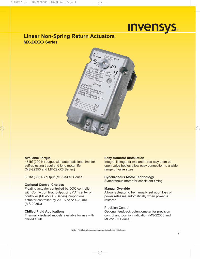
7Note: For illustration purposes only. Actual size not shown.
Available Torque45 lbf (200 N) output with automatic load limit forself-adjusting travel and long motor life(MS-22353 and MF-22XX3 Series)
80 lbf (355 N) output (MF-23XX3 Series)
Optional Control ChoicesFloating actuator controlled by DDC controllerwith Contact or Triac output or SPDT center offcontroller (MF-22XX3 Series) Proportionalactuator controlled by 2-10 Vdc or 4-20 mA(MS-22353)
Chilled Fluid ApplicationsThermally isolated models available for use withchilled fluids
Easy Actuator InstallationIntegral linkage for two and three-way stem upopen valve bodies allow easy connection to a widerange of valve sizes
Synchronous Motor TechnologySynchronous motor for consistent timing
Manual OverrideAllows actuator to bemanually set upon loss ofpower releases automatically when power isrestored
Precision ControlOptional feedback potentiometer for precisioncontrol and position indication (MS-22353 andMF-22353 Series)
Linear Non-Spring Return ActuatorsMX-2XXX3 Series
F-27272.qxd 10/20/2003 10:30 AM Page 7
8
DuraDrive Linear Spring Return Part Numbering SystemTo order your DuraDrive Actuator choose the following:
F-27272.qxd 10/20/2003 10:30 AM Page 8
9
To order your Actuator choose the following:
Non-Spring Return Part Numbering System
F-27272.qxd 10/20/2003 10:30 AM Page 9

10
Actuator Selection Chart
ControlSignal
Part NumberActuator
Code
Actuator Power Input Approximate Stroke Timing in Seconds @ 70F
(21°C)a
a Timing was measured with the actuator mounted on a VB-7XXX Series valve.
Valveb
Size
b See chart below for general information on close-off ratings.
VoltageWiring System
Running Holding
50/60 Hz DC Amps
50/60 HzPowered
Spring ReturnVA W W
Two Position
MA51-7103-000 24Vac ±20% 20-30 Vdc Appliance Wire 5.3 4.1 0.15 1.2 44 19
c Current VB-7XXX Series Valves and obsolete VB-9XXX Series Valves (1-1/4" only).
MA51-7103-100 24Vac ±20% 20-30 Vdc Plenum Cable 5.3 4.1 0.15 1.2 44 19
MA51-7100-000 120 Vac ±10% 50/60 Hz Appliance Wire 7.9 6.2 n/a 2.1 44 19
MA51-7101-000 230 Vac ±10% 50/60 Hz Appliance Wire 7.4 5.4 n/a 2.1 44 19
d Current VB-9XXX Series Valves (2-1/4" to 4") and obsolete VB-9XXX series valves (1-1/2" to 2").
FloatingMF51-7103-000 24Vac ±20% 20-30 Vdc Appliance Wire 6.9 4.7 0.16 2.1 60 16
MF51-7103-100 24Vac ±20% 20-30 Vdc Plenum Cable 6.9 4.7 0.16 2.1 60 16
Proportional
MS51-7103-000e
e 4 - 20 mAdc with AM-708 500 ohm field-instaled resistor.
24Vac ±20% 20-30 Vdc Appliance Wire 6.6 4.2 0.14 1.5 60 16
MS51-7103-100 24Vac ±20% 20-30 Vdc Plenum Cable 6.6 4.2 0.14 1.5 60 16
MS51-7103-020 24Vac ±20% 20-30 Vdc Appliance Wire 6.6 4.2 0.14 1.5 60 16
MS51-7103-120 24Vac ±20% 20-30 Vdc Plenum Cable 6.6 4.2 0.14 1.5 60 16
MS51-7103-030 24Vac ±20% 20-30 Vdc Appliance Wire 6.6 4.2 0.14 1.5 60 16
MS51-7103-130 24Vac ±20% 20-30 Vdc Plenum Cable 6.6 4.2 0.14 1.5 60 16
MS51-7103-040f
f Has 20 Vdc power supply for System 8000 applications.
24Vac ±20% 20-30 Vdc Appliance Wire 7.8 4.9 0.16 3.4 60 16
MS51-7103-140f 24Vac ±20% 20-30 Vdc Plenum Cable 7.8 4.9 0.16 3.4 60 16
MS51-7103-050 24Vac ±20% 20-30 Vdc Appliance Wire 6.6 4.2 0.14 1.5 60 16
MS51-7103-150 24Vac ±20% 20-30 Vdc Plenum Cable 6.6 4.2 0.14 1.5 60 16
MS51-7103-060 24Vac ±20% 20-30 Vdc Appliance Wire 6.6 4.2 0.14 1.5 60 16
MS51-7103-160 24Vac ±20% 20-30 Vdc Plenum Cable 6.6 4.2 0.14 1.5 60 16
Actuator P/N Control TypeClose-Off Pressure Rating (PSI)
1-1/4" 1-1/2" 2" 2-1/2" 3" 4"
MX51-710X-XXXTwo Position,
Floating or Proportional
Need info
Need info
MX51-710X, 105 lbf Series Spring Return Actuators
F-27272.qxd 10/20/2003 10:30 AM Page 10

Actuator Selection Chart
11
ControlAction
Part Number
Actuator Code
Actuator Power Input
Linear Stroke Inches
Approximate Stroke Timing in Seconds @ 70°F
(21°C)a
a Timing was measured with no load applied to the actuator.
Output Force Ratinglb.-(Newton) Valveb
Size
b See chart below for general information on close-off ratings.
Voltage
Running Holding
PoweredSpring Return
50 Hz 60 Hz DC Amps
50/60Hz Min.
Max. Stall
VA W VA W W
Two Position
MA51-7203 593 24Vac ±20% 22-30 Vdc 9.8 7.5 9.7 7.5 .29 2.8 5/8 <100 <35 220(979)
495(2202)
1-1/4" to 2"c
c Current VB-7XXX Series Valves and obsolete VB-9XXX Series Valves (1-1/4" only).
MA51-7200 592 120 Vac ±10% 11.7 8.8 10.0 8.4 N/A 3.6/5.0 5/8 <100 <35 220(979)
495(2202)
1-1/4" to 2"c
MA51-7201 591 230 Vac ±10% 15.5 9.5 10.6 8.5 N/A 4.6/3.3 5/8 <100 <35 220(979)
495(2202)
1-1/4" to 2"c
MA61-7203 596 24 Vac ±20% 22-30 Vdc 9.8 7.5 9.7 7.5 .29 2.8 1-1/16 <190 <40 220(979)
495(2202)
2-1/2"to 4"d
d Current VB-9XXX Series Valves (2-1/4" to 4") and obsolete VB-9XXX series valves (1-1/2" to 2").
MA61-7200 595 120 Vac ±10% 11.7 8.8 10.0 8.4 N/A 3.6/5.0 1-1/16 <190 <40 220(979)
495(2202)
2-1/2"to 4"d
MA61-7201 594 230 Vac ±10% 15.5 9.5 10.6 8.5 N/A 4.6/3.3 1-1/16 <190 <40 220(979)
495(2202)
2-1/2"to 4"d
FloatingMF51-7203 593 24 Vac ±20% 22-30 Vdc 9.8 7.7 9.7 7.7 .30 3.3 5/8 <100 <35 220
(979)495
(2202)1-1/4" to 2"d
MF61-7203 596 24 Vac ±20% 22-30 Vdc 9.8 7.7 9.7 7.7 .30 3.3 1-1/16 <190 <40 220(979)
495(2202)
2-1/2"to 4"c
Proportional2 - 10 Vdc
MS51-7203 593 24 Vac ±20% 22-30 Vdc 9.8 7.4 9.7 7.4 .28 2.9 5/8 <100 <35 220(979)
495(2202)
1-1/4"to 2"d
MS61-7203 596 24 Vac ±20% 22-30 Vdc 9.8 7.4 9.7 7.4 .28 2.9 1-1/16 <190 <40 220(979)
495(2202)
2-1/2"to 4"c
Actuator P/N Control TypeClose-Off Pressure Rating (PSI)
1-1/4" 1-1/2" 2" 2-1/2" 3" 4"
MX51-720X Two Position, Floating or
Proportional
150 100 65 — — —
MX61-720X — — — 33 22 12
MXX1-720X, 220 lbf Series Spring Return Actuators
F-27272.qxd 10/20/2003 10:30 AM Page 11

12
Actuator Selection Chart
Control Action
Part Number
Actuator Code
Actuator Power Input FeedbackTypical Timing in
Sec. @ 75°F for 1/2" (12.7mm) Stroke
Max. Stroke in in. (mm)Voltage
(+20%, -15%)Hz VA 15K ¾ Pot.a
a Running or manually adjusting the actuator before it is mounted to a valve changes the potentiometer setting and could also cause damage.
60 Hz 50 Hz
Floatingbc
b xxxxc xxxx
MF-2220324 (Class 2
Power Supply) 50 60 1.5
No126
±30 sec.151
±30 sec.9/16
(14.3)MF-22303 No
MF-22323 Yes
MF-22XX3, 45 lbf Series Non-Spring Return Actuators
Control Action
Part Number
Actuator Code
Actuator Power Input FeedbackTypical Timing in
Sec. @ 75°F for 1/2" (12.7mm) Stroke
Max. Stroke in in. (mm)Voltage
(+20%, -15%)Hz VA 2 to 10 Vdca
a Running or manually adjusting the actuator before it is mounted to a valve changes the potentiometer setting and could also cause damage.
60 Hz 50 Hz
Proportionalbc
2 - 10 Vdc
b xxxxc xxxx
MS-22353 24 Vac (Class 2Power Supply) 50 60 4 Yes 126 151 9/16
(14.3)
MS-22353, 45 lbf Series Non-Spring Return Actuators
F-27272.qxd 10/20/2003 10:30 AM Page 12

Actuator Selection Chart
13
Control Signal
PartNumber
Actuator Code
Actuator Power InputFeedback (Ohms) Aux
Switch
Stroke in Inches (mm)
Timing in Seconds at 75°F
Voltage(+10/-15%)
Hz Amps Watts 15K pota
a Running or manually adjusting the actuator before it is mounted to a valve changes the potentiometer setting and could also cause damage.
60 Hz 50 Hz
Floatingbc
b xxxxc xxxx
MF-63103
24 Vac(Class II power
supply)50 60 0.30 6
No No
1/2 (13)3/4 (19)1 (25)
6090
120
72108144
MF-63103-500 No Yes
MF-63123 Yes No
MF-63123-500 Yes Yes
MF-631X3, 210 lbf Series Non-Spring Return Actuators
Control Action
Part Number
Actuator Code
Actuator Power Input FeedbackTypical Timing in
Sec. @ 75°F for 1/2" (12.7mm) Stroke
Max. Stroke in in. (mm)Voltage (+20%,
-15%)Hz VA 15K ohm Pot.a
a Running or manually adjusting the actuator before it is mounted to a valve changes the potentiometer setting and could also cause damage.
60 Hz 50 Hz
Floatingbc
b xxxxc xxxx
MF-2320324 (Class 2
Power Supply) 50 60 1.5
No
126 151 9/16(14.3)MF-23303 No
MF-23323 Yes
MF-23XX3, 80 lbf Series Non-Spring Return Actuators
F-27272.qxd 10/20/2003 10:30 AM Page 13

Features:• Two position models
controlled by SPSTcontroller
• Floating models controlledby SPDT floating controllers
• Proportional modelscontrolled by 0-3 Vdc, 6-9Vdc, 0-10 Vdc, 2-10 Vdc, or4-20 mAdc
• 105 lbf (467 N) with 1/2" (13mm) nominal linear stroke
• 24 Vac, 120 Vac, and 230Vac models
• Durable polymer housingsrated for up to NEMA 2/IP54and for use in plenums
• Overload protectionthroughout stroke
• Automatically sets inputspan to match valve travel.
• Compact size to allowinstallation in limited space
• Manual override to allowpositioning of valve andpreload
• Direct mount to valves withintegral linkage
• Five year warranty
14
MX51-710X, 105 lbf Series Spring Return ActuatorsDuraDrive Linear Actuators are designed to mount directly onto two-way or three-way GlobeValves with integral linkage.
Specifications
SpecificationsInputs
Control Signal MA51-710X — Two-Position.
MF51-7103 — Floating point control, 24 Vac.
MS51-7103 — Proportional, 2 - 10 Vdc, 0 - 3 Vdc, 6 - 9 Vdc, 0 - 10 Vdc or 4 - 20 mAdc.
Power Requirements
All 24 Vac circuits are Class 2. All circuits 30 Vac and above are Class 1.
Connections 3
Brushless DC
ft (91 cm) appliance wire or plenum cables, enclosure accepts1/2” (13 mm) conduit connectors. For M20 Metric connector, use AM-756 adaptor.
Motor Type
Outputs
Electrical Position Feedback Voltage (proportional or floating only)
For voltage ranges, the feedback signal is the same range as the input signal. The 4-20mAdc current range and floating actuators have a 2-10 Vdc position feedback signal. The position feedback signal can supply up to 0.5 mA to operate up to four additional slave actuators.
Part Number
Power Input
50/60 Hz 50/60 Hz
Approximate Stroke Timing in Seconds @ 70F
(21°C)a
a Timing was measured with the actuator mounted on a VB-7XXX Series valve.
Voltage Wiring System
RunningDC
Amps
Holding
Powered SRVA W W
MA51-7103-000 24Vac ±20%20-30 Vdc
Appliance Wire 5.3 4.1 0.15 1.2
44 19
MA51-7103-100 Plenum Cable 5.3 4.1 0.15 1.2
MA51-7100-000 120 Vac ±10% 50/60 Hz Appliance Wire 7.9 6.2 n/a 2.1
MA51-7101-000 230 Vac ±10% 50/60 Hz Appliance Wire 7.4 5.4 n/a 2.1
MF51-7103-000
24Vac ±20%20-30 Vdc
Appliance Wire 6.9 4.7 0.16 2.1
60 16
MF51-7103-100 Plenum Cable 6.9 4.7 0.16 2.1
MS51-7103-000 Appliance Wire 6.6 4.2 0.14 1.5
MS51-7103-100 Plenum Cable 6.6 4.2 0.14 1.5
MS51-7103-020 Appliance Wire 6.6 4.2 0.14 1.5
MS51-7103-120 Plenum Cable 6.6 4.2 0.14 1.5
MS51-7103-030 Appliance Wire 6.6 4.2 0.14 1.5
MS51-7103-130 Plenum Cable 6.6 4.2 0.14 1.5
MS51-7103-040b
b Has 20 Vdc power supply for System 8000 applications.
Appliance Wire 7.8 4.9 0.16 3.4
MS51-7103-140b Plenum Cable 7.8 4.9 0.16 3.4
MS51-7103-050 Appliance Wire 6.6 4.2 0.14 1.5
MS51-7103-150 Plenum Cable 6.6 4.2 0.14 1.5
MS51-7103-060 Appliance Wire 6.6 4.2 0.14 1.5
MS51-7103-160 Plenum Cable 6.6 4.2 0.14 1.5
F-27272.qxd 10/20/2003 10:30 AM Page 14

15
Specifications ContinuedMechanical Output torque rating: 105 lbf (467 N)
Approx. Stroke Timing: See Power Requirements table on page 14.
Manual Override: Allows positioning of valve and preload using manual crank.Right/Left Jumper: Permits reverse acting/direct acting linear motion (MS51 only).
EnvironmentTemperature Limits Shipping & Storage: -40 to 160 °F (-40 to 71 °C).
Operating: -22 to 140 °F (-30 to 60 °C).
Temperature Restrictions: For maximum ambient 140 °F (60 °C) the maximum allowable fluid temperature should not exceed 366 °F (186 °C).
Humidity 15 to 95% RH, non-condensing.
Locations NEMA 1. NEMA 2 (enclosure is air plenum rated), UL Type 2 (IEC IP54) with customer supplied water tight conduit connectors.
Agency ListingsUL UL-873, Underwriters Laboratories (File #E9429 Category Temperature-Indicating and Regulating
Equipment).
European Community EMC Directive (89/336/EEC). Low Voltage Directive (72/23/EEC).cUL UL Listed for use in Canada by Underwriters Laboratories. Canadian Standards C22.2 No. 24-93.
Australia This product meets requirements to bear the C-Tick Mark according to the terms specified by the Communications Authority under the Radio Communications Act 1992.
AccessoriesAM-756 Metric Conduit Adapter M20 x 1.5 to 1/2” NPTAM-770 Replacement valve linkage parts kit
AM-764 Linkage kit for damper applications
For MS51-7103 ModelsAM-703 Input rescaling module, adjust signals to 2-10 Vac, zero and span adjust
AM-704 Interface, pulse width modulation (PWM)
AM-705 Positioner (NEMA 4 housing)AM-706 Min and/or manual positioner for flush panel mount
AM-708 500 ohm resistor for 4 to 20 mA control signal
Mounting Dimensions
Dimensions shownare in inches (mm).
6-49/64(172)
3-1/2(89)
6-5/16(160)
8-1/16(205)
1-3/4 (45) Minimum Clearance
5-5/64(129)
MX51-710X, 105 lbf Series Spring Return Actuators
F-27272.qxd 10/20/2003 10:30 AM Page 15
Features:• Two position models
controlled by SPSTcontroller or triacs
• Floating models controlledby SPDT floating controllersor triacs
• Proportional modelscontrolled by 2-10 Vdc, or4-20 mAdc with the additionof a 500 ohm resistor
• 220 lbf (979 N) with 5/8”(16 mm) or 1-1/16" (27 mm)linear stroke
• 24 Vac, 120 Vac, and 230Vac models
• Rugged die-cast housingsrated for NEMA 2, UL Type2/IP54
• Overload protectionthroughout stroke
• Compact size to allowinstallation in limited space
• Manual override to allowpositioning of valve andpreload
• Direct mount to valves withintegral linkage
• Five year warranty
16
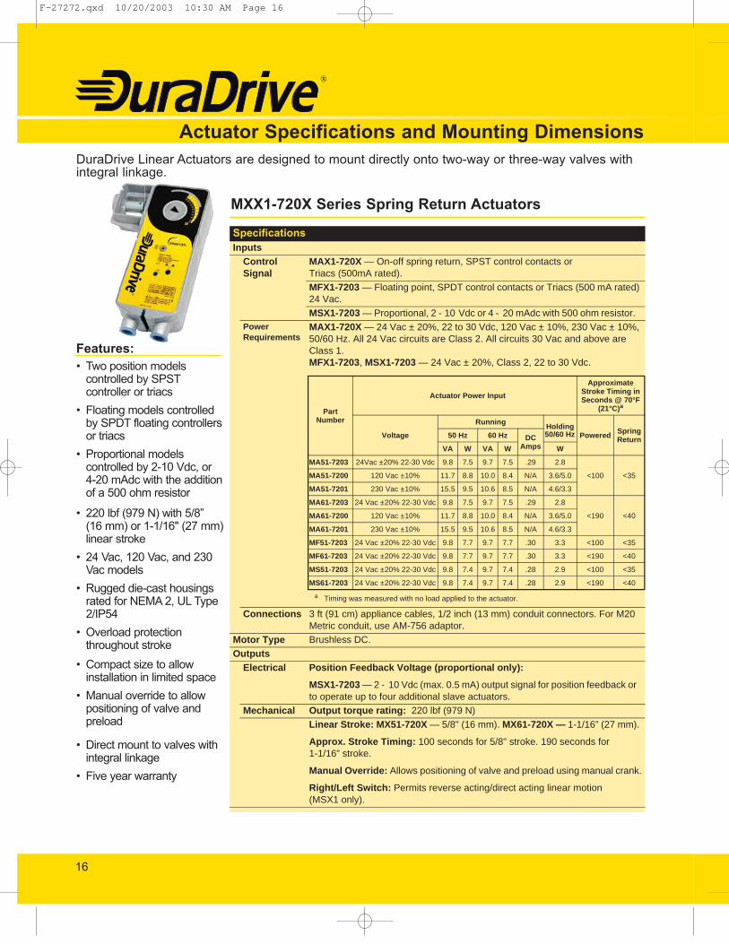
Actuator Specifications and Mounting DimensionsDuraDrive Linear Actuators are designed to mount directly onto two-way or three-way valves withintegral linkage.
MXX1-720X Series Spring Return Actuators
SpecificationsInputs
Control Signal
MAX1-720X — On-off spring return, SPST control contacts orTriacs (500mA rated).
MFX1-7203 — Floating point, SPDT control contacts or Triacs (500 mA rated) 24 Vac.
MSX1-7203 — Proportional, 2 - 10 Vdc or 4 - 20 mAdc with 500 ohm resistor.Power Requirements
MAX1-720X — 24 Vac ± 20%, 22 to 30 Vdc, 120 Vac ± 10%, 230 Vac ± 10%, 50/60 Hz. All 24 Vac circuits are Class 2. All circuits 30 Vac and above are Class 1. MFX1-7203, MSX1-7203 — 24 Vac ± 20%, Class 2, 22 to 30 Vdc.
Connections 3 ft (91 cm) appliance cables, 1/2 inch (13 mm) conduit connectors. For M20 Metric conduit, use AM-756 adaptor.
Motor Type Brushless DC.
OutputsElectrical Position Feedback Voltage (proportional only):
MSX1-7203 — 2 - 10 Vdc (max. 0.5 mA) output signal for position feedback or to operate up to four additional slave actuators.
Mechanical Output torque rating: 220 lbf (979 N)
Linear Stroke: MX51-720X — 5/8" (16 mm). MX61-720X — 1-1/16” (27 mm).
Approx. Stroke Timing: 100 seconds for 5/8" stroke. 190 seconds for1-1/16” stroke.
Manual Override: Allows positioning of valve and preload using manual crank.
Right/Left Switch: Permits reverse acting/direct acting linear motion(MSX1 only).
Part Number
Actuator Power Input
50/60 Hz
Approximate Stroke Timing in Seconds @ 70°F
(21°C)a
Voltage
RunningHolding
Powered Spring Return50 Hz 60 Hz DC
AmpsVA W VA W W
MA51-7203 24Vac ±20% 22-30 Vdc 9.8 7.5 9.7 7.5 .29 2.8
<100 <35MA51-7200 120 Vac ±10% 11.7 8.8 10.0 8.4 N/A 3.6/5.0
MA51-7201 230 Vac ±10% 15.5 9.5 10.6 8.5 N/A 4.6/3.3
MA61-7203 24 Vac ±20% 22-30 Vdc 9.8 7.5 9.7 7.5 .29 2.8
<190 <40MA61-7200 120 Vac ±10% 11.7 8.8 10.0 8.4 N/A 3.6/5.0
MA61-7201 230 Vac ±10% 15.5 9.5 10.6 8.5 N/A 4.6/3.3
MF51-7203 24 Vac ±20% 22-30 Vdc 9.8 7.7 9.7 7.7 .30 3.3 <100 <35
MF61-7203 24 Vac ±20% 22-30 Vdc 9.8 7.7 9.7 7.7 .30 3.3 <190 <40
MS51-7203 24 Vac ±20% 22-30 Vdc 9.8 7.4 9.7 7.4 .28 2.9 <100 <35
MS61-7203 24 Vac ±20% 22-30 Vdc 9.8 7.4 9.7 7.4 .28 2.9 <190 <40
a Timing was measured with no load applied to the actuator.
F-27272.qxd 10/20/2003 10:30 AM Page 16

17
Mounting Dimensions
4 (103)
9-1/4 (235)
9-1/2 (241)
Dimensions shownare in inches (mm).
R
RL
LOCK
2-33/64(64)
10-9/16 (268)9/16(14)
Minimum clearance: 5" for actuator removal.
4 (103)
9-1/4 (235)
7 (178)
R
RL
LOCK
MXX1-720X Series Spring Return Actuators
Specifications ContinuedEnvironment
TAmbient
emperature LimitsShipping and storage: -40 to 160 °F (-40 to 71 °C).Operating: 0 to 140 °F (-18 to 60 °C).Temperature Restrictions:
Humidity 15 to 95% RH, non-condensing.Locations NEMA1. NEMA 2, UL Type 2 (IEC IP54) with customer supplied watertight conduit connectors.
Agency ListingsUL UL-873, Underwriters Laboratories (File #E9429 Category Temperature-Indicating and Regulating
Equipment).European Community EMC Directive (89/336/EEC). Low Voltage Directive (72/23/EEC).cUL UL Listed for use in Canada by Underwriters Laboratories. Canadian Standards C22.2 No. 24-93.Australia This product meets requirements to bear the C-Tick Mark according to the terms specified by the
Communications Authority under the Radiocommunications Act 1992.Accessories
AM-763 1/8” Hexcrank for manual overrideAM-756 Metric conduit adapter M20 x 1.5 to 1/2” NPTAM-731 Mounting kit - MX51-720X (included with actuator)AM-732 Mounting kit - MX61-720X (included with actuator)AM-733 Obsolete VB-9XXX retrofit kit 1-1/2 to 2" valves after 9404 date codeAM-734 Obsolete VB-9XXX retrofit kit 1-1/2 to 2" valves prior to 9404 date codeFor MSX1-7203 ModelsAM-703 Input rescaling module, adjust signals to 2-10 Vac, zero and span adjustAM-704 Interface, pulse width modulation (PWM)AM-705 Positioner (NEMA 4 housing)AM-706 Min and/or manual positioner for flush panel mountAM-708 500 ohm resistor for 4 to 20 mA control signal
ActuatorMax. Allowable Ambient
@ Max. Fluid Temperatures Valve Body
MX51-720X
140 °F (60 °C)@ 281 °F (138 °C) VB-721X, 722X120 °F (49 °C)@ 300 °F (149 °C) VB-73XX100 °F (38 °C)@ 340 °F (171 °C) VB-725X, 726X90 °F (32 °C)@ 366 °F (186 °C) VB-727X, 728X
MX61-720X 140 °F (60 °C)@ 300 °F (149 °C) VB-9XXX, 2-1/2" to 4" current production
F-27272.qxd 10/20/2003 10:30 AM Page 17
Features:• Floating actuator controlled by
SPDT floating controller orDDC controller with equivalentcontrol action (contact or triac)
• Optional control modulecards for proportional control:MFC-8000 for 6 - 9 Vdc andMFC-420 for 4 - 20 mAdc
• 210 lbf (935 N) output withautomatic load limit
• Wide operating ambientrange of 0 to 140°F
• Synchronous motor assuresaccurate stroke timing
• MF-63123 series availablewith a position feedbackpotentiometer
• Self-adjusting travel andposition feedbackpotentiometer mechanisms
• Manual override operationwith automatic release
• Adjustable SPDT auxiliaryswitch on -500 models
• Rugged construction: diecast housing, double thread1/2" dia. stainless steeljackscrew, roller thrustbearings, and all-metal geartrain
• Integral linkage for 1/2" to 2"valves (Optional linkage for2-1/2" to 4" valves)
18
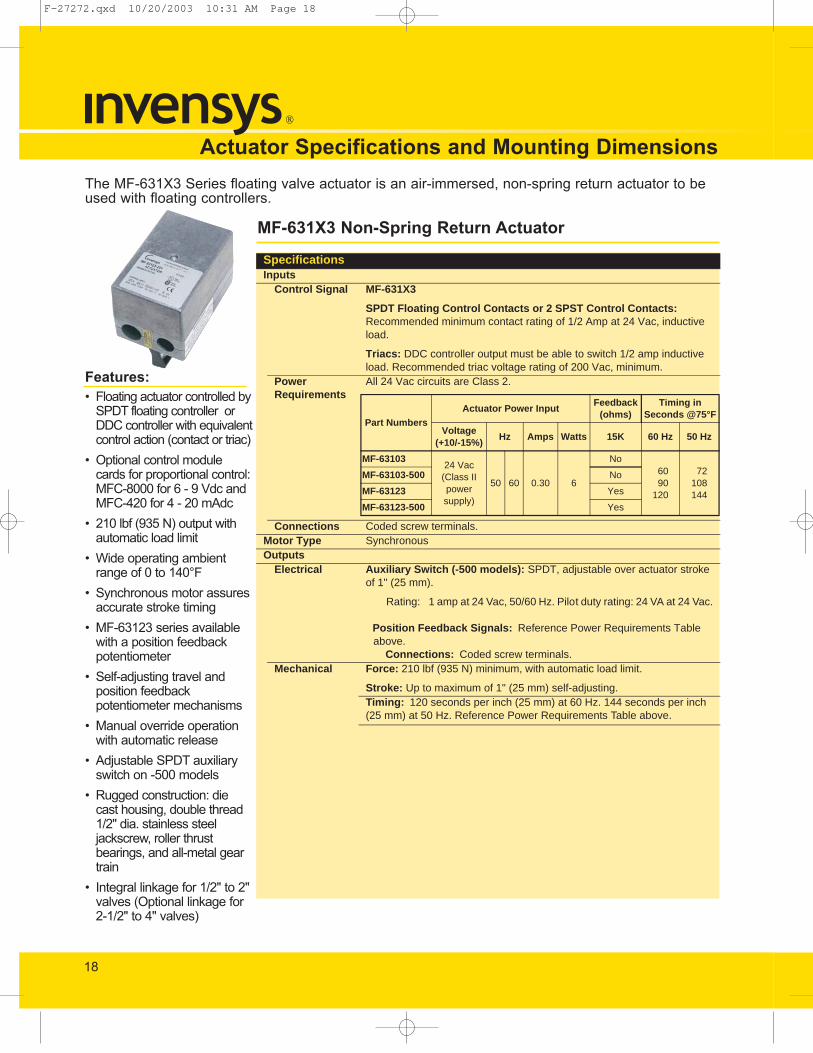
Actuator Specifications and Mounting DimensionsThe MF-631X3 Series floating valve actuator is an air-immersed, non-spring return actuator to beused with floating controllers.
MF-631X3 Non-Spring Return Actuator
SpecificationsInputs
Control Signal MF-631X3
SPDT Floating Control Contacts or 2 SPST Control Contacts: Recommended minimum contact rating of 1/2 Amp at 24 Vac, inductive load.
Triacs: DDC controller output must be able to switch 1/2 amp inductive load. Recommended triac voltage rating of 200 Vac, minimum.
Power Requirements
All 24 Vac circuits are Class 2.
Connections Coded screw terminals.Motor Type SynchronousOutputs
Electrical Auxiliary Switch (-500 models): SPDT, adjustable over actuator stroke of 1" (25 mm).
Rating: 1 amp at 24 Vac, 50/60 Hz. Pilot duty rating: 24 VA at 24 Vac.
Position Feedback Signals: Reference Power Requirements Table above.
Connections: Coded screw terminals.Mechanical Force: 210 lbf (935 N) minimum, with automatic load limit.
Stroke: Up to maximum of 1" (25 mm) self-adjusting.Timing: 120 seconds per inch (25 mm) at 60 Hz. 144 seconds per inch (25 mm) at 50 Hz. Reference Power Requirements Table above.
Part NumbersActuator Power Input
Feedback(ohms)
Timing in Seconds @75°F
Voltage(+10/-15%)
Hz Amps Watts 15K 60 Hz 50 Hz
MF-6310324 Vac
(Class II powersupply)
50 60 0.30 6
No6090
120
72108144
MF-63103-500 No
MF-63123 Yes
MF-63123-500 Yes
F-27272.qxd 10/20/2003 10:31 AM Page 18

19
Mounting Dimensions
5-5/8"(143 mm)
6"(152 mm)
3-5/8"(92 mm)
MF-631X3 Non-Spring Return Actuators
Specifications ContinuedEnvironment
Ambient Temperature Limits
Shipping and storage: -40 to 160°F (-40 to 71°C).
Operating:
Minimum 0°F (-18°C).Maximum See table below.
Humidity 5 to 95% RH, non-condensing.Locations NEMA Type 1.
Agency Listings (Actuator)UL UL-873, Underwriters Laboratories (File # E9429 Category Temperature Indicating and Regulating
Equipment).European Community EMC Directive (89/336/EEC).cUL Certified for use in Canada by Underwriters Laboratories. Canadian Standard C22.2 No. 24-93.
AccessoriesACME-1001-200 Potentiometer board kit for MF-63103 (order separately)MFC-420 Control module card for 4 - 20 mAdc (order separately)MFC-8000 Control module card for 6 - 9 Vdc (order separately)YBA-519-1 Locknuts, two are included with the actuatorValve LinkageAV-671 Linkage for 1-1/2" and 2" obsolete VB-9XXX valves (order separately)AV-672 Linkage for 2-1/2" to 4" VB-9XXX valves, except VB-9323 (order separately)AV-673 Linkage for 1/2" to 2" Johnson Controls VB-3754, VB-3924, and VB-4324 valvesAV-674 Linkage for 1/2" to 3" Honeywell V5011F, V5011G, and V5013F valves
Valve BodyPart Number
Maximum Allowable Ambient Temperaturea
Maximum Allowable Fluid Temperature
a When used with chilled water, the maximum allowable ambient temperture is 140 °F (60 °C). When used with hot water, the maximum allowable ambient temperature is affected by heat transferance from the valve. This allows slightly lower temperatures, as listed, for proper operation of the actuator.
Temperature °F (°C)
VB-7213-0-4-PVB-7214-0-4-PVB-7215-0-4-PVB-9213-0-X-P
Maximum Ambient TemperatureMax. Allowable Fluid Temperature
125 (52)281 (138)
VB-7253-0-4-P Maximum Ambient TemperatureMax. Allowable Fluid Temperature
100 (38)340 (171)
VB-7273-0-4-P Maximum Ambient TemperatureMax. Allowable Fluid Temperature
100 (38)366 (185)
VB-7313-0-4-PVB-7314-0-4-PVB-7315-0-4-PVB-9313-0-X-P
Maximum Ambient TemperatureMax. Allowable Fluid Temperature
125 (52)281 (138)
VB-9313-0-5-P Maximum Ambient TemperatureMax. Allowable Fluid Temperature
100 (38)300 (149)
VB-7323-0-4-P Maximum Ambient TemperatureMax. Allowable Fluid Temperature
125 (52)281 (138)
F-27272.qxd 10/20/2003 10:31 AM Page 19

Features:• Proportional actuator
controlled by 2 - 10 Vdcor 4 - 20 mA
• 45 lbf (200 N) output withautomatic load limit forself-adjusting travel andlong motor life
• Synchronous motor forconsistent timing
• Manual override withautomatic release
• 2 - 10 Vdc actuatorposition feedback signal
• Integral linkage for allstandard 1/2" to 1-1/4"IBS two-way stem-upopen and three-way valvebodies for a wide varietyof applications
• Compact size forapplication flexibility
• Rugged construction withdie cast housing
• 100 ohm inputimpedance for the 4 - 20mA input
20
Actuator Specifications and Mounting Dimensions
MS-22353 Non-Spring Return ActuatorSpecificationsInputs
Control Signal MS-22353 — 2 - 10 Vdc or 4 - 20 mAdc, Proportional control signals (fixed span and start point).Input Impedance,
100 ohm minimum for voltage input.100 ohm for current input.
Power Requirements
Connections 4 foot (1.2 m) color coded 18 AWG, plenum cable rated for UL.Motor Type SynchronousOutputsElectrical Position Feedback Signal: 2 - 10 Vdc non-adjustable.
Connections: 4 foot (1.2 m) color coded 18 AWG, plenum cable rated for UL.
Mechanical Force: 45 lbf (200 N) minimum with automatic load limit. Stroke: Up to 9/16" (14.3 mm) maximum, self-adjusting.Timing: Reference Power Requirements table above.
EnvironmentAmbient Temperature Limits
Shipping and storage: -40 to 160°F (-40 to 71°C).
Operating:
Minimum 40°F (4°C).Maximum See table below.
Part Number
Actuator Power InputTypical Timing in Sec.
@ 75°F for 1/2" (12.7mm) Stroke
Voltage(+20%, -15%)
Hz VA 60 Hz 50 Hz
MS-2235324 Vac (Class 2Power Supply)
50 60 4 126 151
Valve Body Part Numbera
a MS-22353 actuators may also be used with VB-9XXX valves. Refer to Invensys Building Systems Components, F-25683, for available valves.
Valve Sizes Close-off Pressure (psi)b Nominal
b Close off ratings describe only the differential pressure which the actuator can close with adequate seating force. Refer to Invensys Building Systems Components, F-25683
Two-Way ValvesVB-7211VB-7212VB-7213VB-7214VB-7215c
c Metric thread 15 to 32 mm (Rp 1/2 to Rp 1-1/4).
1/2" 1303/4" 801" 40
1-1/4" 25
Three-Way Mixing ValvesVB-7312VB-7313VB-7314VB-7315c
1/2" 1303/4" 801" 40
1-1/4" 25
Actuator Part
Number
Temperature of Media in the Valve Body
(Check Rating of the Valve)
Maximum Ambient
Temperature of Actuator
Dew Point Temperaturea
a Dew point temperature applies only to chilled water applications.
Minimum Maximum
MS-22353 40°F (4°C)b281°F
(138°C)115°F (46°C) 88°F maximum with 40°F fluid
(31°C maximum with 4°C fluid)b
b The dew point temperature cannot be more than 48°F (26.7°C) above the fluid temperature.
220°F(104°C)
140°F(60°C)
The MS-22353 Proportional Valve Actuator is a non-spring return actuator used with proportional 2 - 10 Vdcor 4 - 20 mAdc controllers and standard 1/2” to 1-1/4” two-way and three-way valve bodies for control ofheating and cooling coils.
F-27272.qxd 10/20/2003 10:31 AM Page 20

21
Specifications ContinuedEnvironment Continued
Humidity 5 to 95% RH, non-condensing. See Temperature Limits Table page 20 for maximum dew point temperature.
Locations NEMA Type 1.
Enclosure Protection Class
IP31 according to EN 60529, BS EN 60529.
Agency Listings
UL UL 873, Underwriters Laboratories (File # E9429 Category Temperature-Indicating and Regulating Equipment).
cUL Certified for use in Canada by Underwriters Laboratories. Canadian Standards C22.2 No. 24-93.
European Community EMC Directive (89/336/EEC). Low Voltage Directive (72/23/EEC).
Accessories
AV-641 Valve linkage kit (replacement parts only, order separately)
AV-642 Four-way valve linkage kit for Controlli valve bodies
AV-644 Valve linkage kit (included with MS-22353 actuator)
AM-756 Metric male 20 mm conduit fitting (m20 x 1.5 - 8g) 11 mm nominal thread length
Mounting Dimensions
3-5/16(84)
3 (76)
5-9/16 (141)Optional metric conduit fitting (AM-756) adds 37/64" (15 mm) to overall length.Dimensions shown are in inches (mm).
MS-22353 Non-Spring Return Actuator
F-27272.qxd 10/20/2003 10:31 AM Page 21

Features:• Floating actuator
controlled by DDCcontroller with contact orTriac output or SPDTcenter off controller
• 45 lbf (200 N) output withautomatic load limit forself-adjusting travel andlong motor life
• Synchronous motor forconsistent timing
• Manual override withautomatic release
• Optional feedbackpotentiometer availablefor precision control orposition indication
• Integral linkage for allstandard 1/2" to 1-1/4"IBS two-way stem-upopen and three-way valvebodies for a wide varietyof applications
• Compact size forapplication flexibility
• Rugged construction withdie cast housing
22
Actuator Specifications and Mounting DimensionsThe MF-22XX3 Series Floating Valve Actuator is a non-spring return actuator used with floatingDDC controllers and standard 1/2” to 1-1/4” two-way and three-way valve bodies for control ofheating and cooling coils.
MF-22XX3 Series Actuators
SpecificationsInputs
Control Signal MF-22XX3
SPDT Center Off (Floating) Control Contacts or Two SPST Control Contacts — Minimum rating of 250 mA @ 24 Vac inductive load.
Two Triacs — DDC output must be able to switch 250 mA (24 VA) inductive load (150 Vac minimum).
Power Requirements
Connections 4 foot (1.2 m) color coded 18 AWG, plenum cable rated for UL and IEC-332-3 category C.
Motor Type SynchronousOutputsElectrical Position Feedback Signal: 15K ohm nominal potentiometer.
Reference Power Requirements table above.Connections: 4 foot (1.2 m) color coded 18 AWG, plenum cable rated for UL.
Mechanical Force: 45 lbf (200 N) minimum with automatic load limit. Stroke: Up to 9/16" (14.3 mm) maximum, self-adjusting.Timing: Reference Power Requirements table above.Manual Operator: Allows actuator to be manually set at any position upon loss of power. Releases automatically when power is restored.
Part Number
Actuator Power Input FeedbackTypical Timing in
Sec. @ 75°F for 1/2" (12.7mm) Stroke
Voltage (+20%, -15%) Hz VA 15k 3/4 Pot. 60 Hz 50 HzMF-22203
24 (Class 2Power Supply)
50 60 1.5No
126±30 sec.
151±30 sec.
MF-22303 NoMF-22323 Yes
Valve Body Part Numbera
a MF-22XX3 actuators may also be used with VB-9XXX valves. Refer to Invensys Building Systems Components Catalog, F-25683, for available valves.
Valve Sizes Close-off Pressure (psi)b Nominal
b Close off ratings describe only the differential pressure which the actuator can close with adequate seating force. Refer to Invensys Building Systems Components Catalog, F-25683.
Two-Way ValvesVB-7211VB-7212VB-7213VB-7214VB-7215c
c Metric thread 15 to 32 mm (Rp 1/2 to Rp 1-1/4).
1/2" 1303/4" 801" 40
1-1/4" 25
Three-Way Mixing ValvesVB-7312VB-7313VB-7314VB-7315c
1/2" 1303/4" 801" 40
1-1/4" 25
F-27272.qxd 10/20/2003 10:31 AM Page 22

23
Specifications ContinuedEnvironment
Ambient Temperature Limits
Shipping and storage: -40 to 160°F (-40 to 71°C).
Operating:
Minimum 40°F (4°C).Maximum See table below.
Humidity 5 to 95% RH, non-condensing. See Temperature Limits table above for maximum dew point temperature.Locations NEMA Type 1.Enclosure Protection Class
Designed to meet IP31Class, according to EN 60529, BS EN 60529.
Agency ListingsUL UL 873, Underwriters Laboratories (File # E9429 Category Temperature-Indicating and Regulating
Equipment).cUL Certified for use in Canada by Underwriters Laboratories. Canadian Standards C22.2 No. 24-93.European Community EMC Directive (89/336/EEC).
AccessoriesAV-641 Valve linkage kit (replacement parts only, order separately)AV-642 Four-way valve linkage kit for Controlli valve bodiesAV-644 Valve linkage kit (included with MS-22353 actuator)AM-756 Metric male 20 mm conduit fitting (m20 x 1.5 - 8g) 11 mm nominal thread length
Part Number
Temperature of Media in the Valve Body
(Check Rating of the Valve)
Maximum Actuator Ambient
Temperature
Dew Point Temperature
Minimum Maximum
MF-22203 70°F (21°C)
281°F (138°C) 115°F (46°C)Non-condensing a
a Do not use MF-22203 models in chilled water applications.
220°F (104°C) 140°F (60°C)
MF-22303MF-22323
40°F b
(4°C)281°F (138°C) 115°F (46°C) 88°F Dew Point maximum with 40°F fluid
(31°C Dew Point maximum with 4°C fluid) b
b The dew point temperature cannot be more than 48°F (26.7°C) above the fluid temperature.
220°F (104°C) 140°F (60°C)
Mounting Dimensions
MF-22XX3 Non-Spring Return Series Actuators
3-5/16(84)
3 (76)
5-9/16 (141)Optional metric conduit fitting (AM-756) adds 37/64" (15 mm) to overall length.Dimensions shown are in inches (mm).
F-27272.qxd 10/20/2003 10:31 AM Page 23

Features:• Floating actuator
controlled by DDCcontroller with contact orTriac output or SPDTcenter off controller
• 80 lbf (355 N) of output• Synchronous motor for
consistent timing• Manual override with
automatic release• Optional feedback
potentiometer availablefor precision control orposition indication
• Integral linkage for allstandard 1/2" to 2" IBStwo-way stem-up openand three-way valvebodies for a wide varietyof applications
• Compact size forapplication flexibility
• Rugged construction withdie cast housing
24
Actuator Specifications and Mounting DimensionsThe MF-23XX3 Series Floating Valve Actuator is a non-spring return actuator used with floatingDDC controllers that operate standard 1/2” to 2” two-way and three-way valve bodies for control ofheating and cooling coils.
MF-23XX3 Non-Spring Return Series Actuators
SpecificationsInputs
Control Signal MF-23XX3
SPDT Center Off (Floating) Control Contacts or Two SPST Control Contacts — Minimum rating of 250 mA @ 24 Vac inductive load. DDC controller must time out the control signal to the actuator after three minutes or less
Two Triacs — DDC output must be able to switch 250 mA (24 VA) inductive load (150 Vac minimum).
Power Requirements
Connections 4 foot (1.2 m) color coded 18 AWG, UL rated plenum cable.Motor Type SynchronousOutputsElectrical Position Feedback Signal: 15K ohm nominal potentiometer.
Reference Power Requirements table above.Connections: 4 foot (1.2 m) color coded 18 AWG, UL rated plenum cable.
Mechanical Force: 80 lbf (355 N) minimum at low line voltage (-15%). Stroke: Up to 9/16" (14.3 mm) maximum, self-adjusting.Timing: Reference Power Requirements table above.Manual Operator: Allows actuator to be manually set at any position upon loss of power. Releases automatically when power is restored.
Part Number
Actuator Power Input FeedbackTypical Timing in
Sec. @ 75°F for 1/2" (12.7mm) Stroke
Voltage (+20%, -15%) Hz VA 15 ohm Pot. 60 Hz 50 HzMF-23203
24 (Class 2Power Supply)
50 60 1.5No
126 151MF-23303 NoMF-23323 Yes
Valve Body Part Numbera
a Close off ratings describe only the differential pressure which the actuator can close with adequate seating force. Refer to Invensys Building Systems Components Catalog, F-25683.
Valve Sizes Close-off Pressure (psi)b Nominal
Two-Way ValvesVB-7213VB-7214VB-7215c
VB-7253VB-7273
1/2" 2503/4" 1701" 80
1-1/4" 501-1/2" 33
2" 16
Three-Way Mixing ValvesVB-7312VB-7313VB-7314VB-7315c
1/2" 2503/4" 1701" 80
1-1/4" 501-1/2" 33
2" 16Three-Way Diverting Valves
VB-7332 All Sizes 250
F-27272.qxd 10/20/2003 10:32 AM Page 24

25
Specifications ContinuedEnvironment
Ambient Temperature Limits
Shipping and storage: -40 to 160°F (-40 to 71°C).
Operating:
Minimum 40°F (4°C).Maximum See table below.
Humidity 5 to 95% RH, non-condensing. See Temperature Limits table above for maximum dew point temperature.Locations NEMA Type 1.Enclosure Protection Class
Designed to meet IP31Class, according to EN 60529, BS EN 60529.
Agency ListingsUL UL 873, Underwriters Laboratories (File # E9429 Category Temperature-Indicating and Regulating
Equipment).cUL Certified for use in Canada by Underwriters Laboratories. Canadian Standards C22.2 No. 24-93.European Community EMC Directive (89/336/EEC).
AccessoriesAV-644 Valve linkage kit (included with MF-23XX3 actuator)AM-756 Metric male 20 mm conduit fitting (m20 x 1.5 - 8g) 11 mm nominal thread length
Part Number
Temperature of Media in the Valve Body
(Check Rating of the Valve)
Maximum Actuator Ambient
Temperature
Dew Point Temperature
Minimum Maximum
MF-23203 70°F (21°C)
281°F (138°C) 115°F (46°C)Non-condensing a
a Do not use MF-23203 models in chilled water applications.
220°F (104°C) 140°F (60°C)
MF-23303MF-23323
40°F b
(4°C)281°F (138°C) 115°F (46°C) 88°F Dew Point maximum with 40°F fluid
(31°C Dew Point maximum with 4°C fluid) b
b The dew point temperature cannot be more than 48°F (26.7°C) above the fluid temperature.
220°F (104°C) 140°F (60°C)
Mounting Dimensions
MF-23XX3 Non-Spring Return Series Actuators
3-5/16(84)
3 (76)
5-9/16 (141)Optional metric conduit fitting (AM-756) adds 37/64" (15 mm) to overall length.Dimensions shown are in inches (mm).
F-27272.qxd 10/20/2003 10:32 AM Page 25
26
MA
51-7
10X
Ser
ies
MA
X1-
720X
Ser
ies
MF
X1-
7103
Ser
ies
MF
X1-
7203
Ser
ies
MS
51-7
103
Ser
ies
MS
X1-
7203
Ser
ies
MF
-631
X3
Ser
ies
MF
-22X
X3
Ser
ies
MF
-23X
X3
Ser
ies
MS
-223
53 S
erie
s
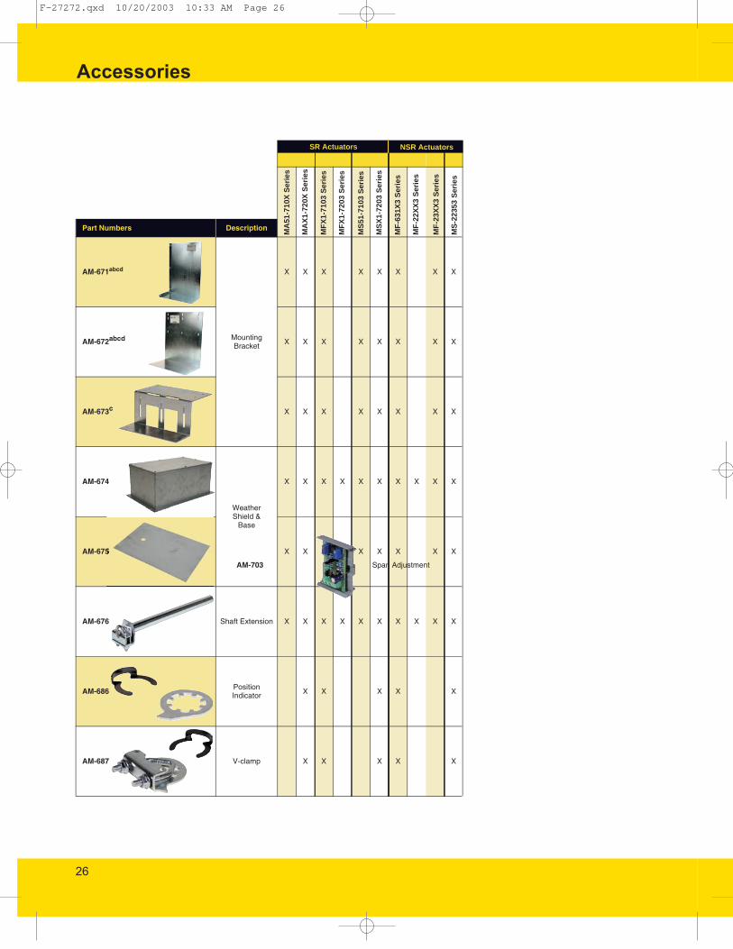
SR Actuators NSR Actuators
Accessories
F-27272.qxd 10/20/2003 10:33 AM Page 26

27
Accessories
F-27272.qxd 10/20/2003 10:34 AM Page 27

28
Accessories
F-27272.qxd 10/20/2003 10:35 AM Page 28

29
Accessories
F-27272.qxd 10/20/2003 10:35 AM Page 29

30
Accessories
F-27272.qxd 10/20/2003 10:37 AM Page 30
31
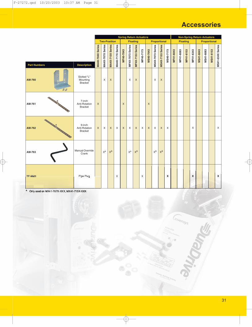
Accessories
F-27272.qxd 10/20/2003 10:37 AM Page 31

48
Accessories
F-27272.qxd 10/20/2003 10:38 AM Page 32
49
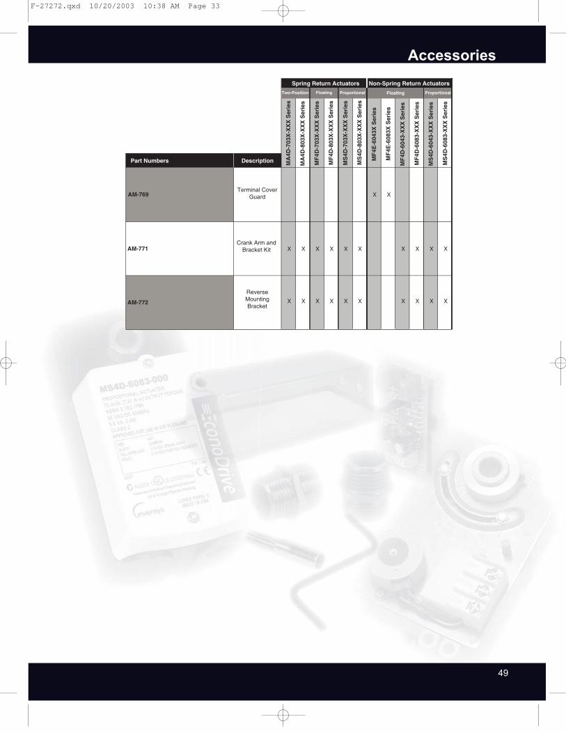
Accessories
F-27272.qxd 10/20/2003 10:38 AM Page 33

50
Invensys Building Systems assumes no responsibility for guaranteeing the acceptability of anysuggested replacement in this section. The emphasis has been placed on providing a replacementactuator of the same specifications wherever possible. The user must determine the acceptabilityof the substitution by reviewing the actuator specifications.
The cross reference tables list Invensys Building Systems Direct-Coupled Actuators which mayreplace obsolete SEC and Belimo devices, as well as older Invensys devices. The tables listtwo-position, floating, and proportional actuators. The devices to be replaced are listedalphanumerically in the left-hand column, with the suggested Invensys replacement in the centercolumn. The replacement actuators in this list represent what we believe are equivalent units.
Direct Coupled Actuator Cross Reference
F-27272.qxd 10/20/2003 10:39 AM Page 34

51
Direct Coupled Actuator Cross Reference
F-27272.qxd 10/20/2003 10:39 AM Page 35

52
Direct Coupled Actuator Cross Reference
F-27272.qxd 10/20/2003 10:39 AM Page 36

53
Direct Coupled Actuator Cross Reference
F-27272.qxd 10/20/2003 10:39 AM Page 37

54
Direct Coupled Actuator Cross Reference
F-27272.qxd 10/20/2003 10:39 AM Page 38

55
Notes
F-27272.qxd 10/20/2003 10:39 AM Page 39

Invensys Climate ControlsAmericas1354 Clifford Avenue, (61111)P.O. Box 2940Loves Park, Illinois 61132-2940(888) 444-1311(815) 637-3000Fax: (815) 637-5300
www.invensysibs.com
F-27272 9-03 Printed in U.S.A.
Copyright 2003 Invensys plc. All rights reserved.No part of this document may be photocopied or reproduced by anymeans, or translated to another language without prior writtenconsent of Invensys. All specifications are nominal and may changeas design improvements are introduced. Invensys shall not be liablefor damages resulting from misapplication or misuse of its products.
Invensys, DuraDrive, and DuraLynx are trademarks of Invensys plcand its subsidiaries and affiliates.
All other trademarks are the property of their respective owners.
F-27272.qxd 10/20/2003 10:39 AM Page 40