Embed Size (px)
Citation preview

.
Linear Actuator Sizing,Unbalanced Trim
Sizing & Selection 16
IntroductionAn important part of selecting the correct control valveis the proper sizing of its actuator. In throttling services,three questions must be answered:
1. Will the actuator handle the throttling differentialpressure?
2. Will the actuator provide sufficient thrust to overcomeapplication pressures to open or close the valve,and generate enough seat loading for tight shutoff?
3. Will the spring fail the valve in the proper direction?
With on/off services, only questions 2 and 3 must beanswered.
The equations in this section use the following vari-ables:
AL
= Lower cylinder area, in2
AU
= Upper cylinder area, in2
AS
= Area of the seat, in2 (see Table 16-IV orequation 16.1)
AStem
* = Plug stem cross-sectional area, in2 (seeTable 16-IV or equation 16.3)
AR
= Area of the seat retainer bore, in2 (seeequation 16.2)
P1
= Pressure on upstream side of the valve,psig
P2
= Pressure on downstream side of the valve,psig
PS
= Air supply pressure, psigS
E= Spring force with the spring extended to full
stroke, lbs (see Table 16-VI)S
R= Spring force with the spring fully retracted,
lbs (see Table 16-VI)S
FC30= Spring force at 30 percent of stroke in fail-
closed actuators, lbs (see Table 16-VI orequation 16.4)
SFO30
= Spring force at 30 percent of stroke in fail-open actuators, lbs (see Table 16-VI orequation 16.5)
FP
= Packing friction, lbs (see Table 16-V)R
SL= Required seat load to achieve desired
shutoff, lbs (see equation 16.6)
Rev. 4/94
* Use effective bellows area for Guardian valves, see Table 16-I. For Guardian II valves, see page 16-15.
When an actuator’s stroke length exceeds the longeststroke length shown for that size actuator on Table 16-VI, the actuator will not have a spring. For actuatorswithout a spring, S
E= S
R= 0.
The areas of the seat, AS, and the seat retainer bore, A
R,
are calculated using the following equations. Note thatthe area of the seat retainer bore is not used when sizingactuators for valves with standard trim or when sizingactuators for Class 150 through 600 MegaStream valves
πdS2
AS
= (16.1) 4
π(dS+0.125)2
AR
= (16.2) 4
Where:
dS
= The seat orifice diameter, inches (Trim Num-ber)
The plug stem cross-sectional area, Astem
, is calculatedusing the following equation:
πdstem
2
Astem
= (16.3) 4
Table 16-I: Guardian Metal BellowsEffective Area
Model Body Size Bellows EffectiveNumber (inches) psi Rating Bellows Area
1-LP 1⁄2, 3⁄4, 1 160 .886
1-HP 1⁄2, 3⁄4, 1 310 .886
2-LP 11⁄2, 2 160 1.916
2-HP 11⁄2, 2 310 1.916
3-LP 3 160 2.835
3-HP 3 310 2.835
4-LP 4 160 3.343
4-HP 4 310 3.343
16-1

Where:
dstem
=The plug stem diameter, inches (see Table 16-IV)
The spring forces at 30 percent of stroke in fail-closedand fail-open actuators, S
FC30 and S
FO30, are calculated
using the following formulas:
SFC30
= SE + R
S (0.30) S (16.4)
SFO30 = SR - RS (0.30) S (16.5)
Where:
RS
= Spring rate, lb/in (from Table 16-VI)
S = Stroke length, inches
The required seat load, RSL
, is calculated using thefollowing equation:
RSL
= πdCL
S(16.6)
Where:
LS
= Seat load per circumferential inch toachievedesired shutoff, lbs/in (from Table 8-II)
dC
= The diameter of the seating contact surface,in (from the following table)
Trim Type d C=
StandardMegaStream Trim NumberTiger-Tooth
CavControl Trim Number +ChannelStream 0.125 inch
Step 1: Determine Actuator’s MaximumAllowable Throttling Pressure Drop(Not required for on/off service)
Refer to Table 16-IV to find the standard actuator for thegiven body size.
Determine the maximum allowable throttling pressuredrop (∆P
a) that the selected actuator can handle by
using equations (16.7) and (16.8):
Air-to-open, flow-over: or air-to-close, flow-over:
ACJ
O ∆Pa = ≈≈≈≈≈ (16.7)
AS
Air-to-close, flow-under; or air-to-open, flow-under:
ACJ
C ∆Pa = ≈≈≈≈≈ (16.8)
AS
16-2
Where:
∆Pa
= Maximum allowable throttling pressure drop,psi
AC
= Area of cylinder actuator, square inches (seeTable 16-III; for air-to-open flow, use thelower cylinder area; for air-to-close flow, useupper cylinder area)
AS = Area of the seat, square inches
JO
= Air supply adjustment factor for flow-over (seeTable 16-II)
JC
= Air supply adjustment factor for flow-under(see Table 16-II)
Table 16-II:Air Supply Stiffness Factors
Supply Pressure J C JO
30 14.1 14.145 28.2 20.760 37.6 28.280 56.4 35.8
100 75.2 42.4150 118.0 61.2
Compare the maximum allowable throttling pressuredrop to the actual pressure drop. If the actual throttlingdrop is less than ∆P
a, the selected actuator is sufficient.
However, if the actual throttling drop is greater than∆P
a, the next larger actuator size should be chosen and
the above calculation should be repeated.
The maximum allowable throttling pressure drop mayalso be selected by referring to the appendix at the endof this section. To use these tables, follow the proce-dure below:
A) Select the correct table based on the trim sizeused on the valve.
B) Find the correct air supply pressure in the leftcolumn.
C) Looking to the right, find the allowable throttlingdrop (∆P
a) for the various actuator sizes and air
actions (air-to-open or air-to-close).

Table 16-IV: Standard Unbalanced Valve/Actuator Data
Valve Size Rating Full Area Seat Area Stem Stem Area Std. Act. Stroke(inches) Class Trim Size (sq. in.) Dia. (sq. in.) Size* (inches)
1/2 150-600 .50 .196 .562 .248 25 .753/4 150-2500 .72 .405 .562 .248 25 .75
1 150-600 .81 .518 .562 .248 25 .751 900-1500 .81 .518 .562 .248 25 .751 2500 .72 .405 .562 .248 25 .75
11/2 150-600 1.25 1.23 .875 .601 25 1.0011/2 900-1500 1.25 1.23 .875 .601 50 1.0011/2 2500 1.00 .785 .875 .601 50 .75
2 150-600 1.62 2.07 .875 .601 25 1.502 900-1500 1.62 2.07 .875 .601 50 1.502 2500 1.25 1.23 .875 .601 50 1.00
3 150-600 2.62 5.41 1.125 .99 50 2.003 900-1500 2.62 5.41 1.5 1.77 100 2.003 2500 2.00 3.14 1.125 .99 100 1.50
4 150-600 3.50 9.62 1.125 .99 50 2.504 900-1500 3.50 9.62 1.5 1.77 100 2.504 2500 2.62 5.41 1.5 1.77 100 2.00
6 150 5.00 19.63 1.125 .99 50 3.006 300-1500 5.00 19.63 2.0 3.14 100 3.006 2500 4.00 12.57 2.0 3.14 100 3.00
8 150 6.25 30.68 1.5 1.77 100 4.008 300-600 6.25 30.68 2.0 3.14 100 4.008 900-1500 6.25 30.68 2.5 4.91 100 4.008 2500 5.00 19.63 2.5 4.91 100 3.00
10 150 8.75 60.13 2.0 3.14 100 4.0010 300-600 8.75 60.13 2.5 4.91 100 4.0010 900-1500 8.00 50.27 3.0 7.07 100 4.0010 2500 6.25 30.68 3.0 7.07 100 4.00
12 150 9.50 70.88 2.0 3.14 100 4.0012 300-600 9.50 70.88 3.0 7.07 100 4.0012 900-2500 8.00 50.27 3.0 7.07 100 4.00
14 150 11.00 95.03 3.0 7.07 100 4.0014 300-600 11.00 95.03 3.0 7.07 100 4.00
* Minimum standard actuator size. Oversized actuators may be required for large pressure drops.
Table 16-III: Actuator Data
Cylinder Cylinder Upper Cylinder Lower Cylinder Stem Dia. Stem Area Max. Vol. OverSize Bore Dia.(in.) Area (sq. in.) Area (sq. in.) (in.) (sq. in.) Piston (cu.in.)
25 5.50 23.76 22.97 1.00 0.79 100
50+ 7.75 47.17 46.39 1.00 0.79 331
50 7.75 47.17 45.67 1.38 1.50 331
100+ 11.00 95.03 93.26 1.50 1.77 1031
100 11.00 95.03 91.06 2.25 3.98 1031
200 15.50 188.7 184.7 2.25 3.98 2087
300 19.50 298.6 292.7 2.75 5.94 3733
400* 15.50 371.5 365.5 2.75 5.94 3033
500 25.25 500.7 494.8 2.75 5.94 5519
600* 19.50 590.2 583.1 3.00 7.07 5661
* Tandem, double piston configuration + Used as oversized actuators in place of the next smaller actuator
16-3

Cylinder Stroke Spring Rate SE: Spring S
FC30S
R: Spring S
R: Spring S
FO30S
E: Spring
(inches) Design (lb/in) Extended (lbs) Retracted Retracted (lbs) Extended(lbs) (lbs) (lbs) (lbs)
3⁄4 STD 180 281 322 416 450 410 315
1 STD 180 236 290 416 450 396 270
25 11⁄2 STD 180 146 227 416 450 369 1803⁄4 DUAL 447 629 728 964
1 DUAL 447 629 762 1075
11⁄2 DUAL 447 405 606 1075
11⁄2 STD 164 369 443 615 656 582 410
2 STD 164 287 385 615 656 558 328
21⁄2 STD 164 205 328 615 656 533 246
50 3 STD 164 123 271 615 656 508 164
11⁄2 DUAL 447 1194 1395 1864
2 DUAL 447 970 1238 1864
21⁄2 DUAL 447 747 1082 1864
3 DUAL 447 523 925 1864
2 STD 300 1125 1305 1725 1725 1545 1125
21⁄2 STD 300 975 1200 1725 1725 1500 975
100 3 STD 300 825 1095 1725 1725 1455 825
4 STD 300 525 885 1725 1725 1365 525
2 HEAVY 535 2098 2419 3168
thru 21⁄2 HEAVY 535 1831 2232 3168
3 HEAVY 535 1563 2045 3168
4 HEAVY 535 1028 1670 3168
2 DUAL 885 3471 4002 5241
600 21⁄2 DUAL 885 3029 3693 5241
3 DUAL 885 2586 3383 5241
4 DUAL 885 1701 2763 5241
TABLE 16-V: Typical Stem Packing Friction ForcesNote: All numbers in pounds-force
Plug Stem Teflon Teflon Glass and Standard Twin Braided Braided SafeGuard SafeGuardDiameter* Single V Twin V Carbon-filled Grafoil Grafoil PTFE AFPI SureGuard SureGuard(inches) Teflon Single V Twin V
0.56 44 49 45 356 642 44 271 52 680.88 49 54 63 560 842 49 344 70 891.13 54 50 78 712 1001 54 399 85 106
1.50 64 60 103 954 1239 64 486 111 1352.00 82 75 141 1272 1557 82 600 149 1772.50 105 90 184 1590 1875 105 714 192 2253.00 133 105 232 1908 2193 133 829 239 279
TABLE 16-VI: Cylinder Actuator Spring Data
Air-to-open (Air-to-retract) Air-to-close (Air-to-extend)
16-4

ofof
ofld
he
hisedd.s.
helsohis
ug
eshe
uger.ed
Step 2: Determine Actuator Size ForActuation ThrustCalculate the actuator cylinder areas required by usingthe applicable group of equations in the following tables.Compare the calculated areas to the correspondingareas for the actuator size selected in Step 1. Actuatorareas are listed in Table 16-III. If the calculated areasare less than or equal to the corresponding areas for theselected actuator, the actuator size is adequate. If thecalculated areas are larger, an actuator with cylinderareas larger than the calculated areas must be se-lected.
When determining the required actuator size, variousservice conditions should be considered. For eachsizing equation, the conditions to be considered for thatequation are listed with the equation. Each equationshould be evaluated for each listed condition that willactually occur. The condition numbers refer to thefollowing list.
Service Conditions to be considered:1. P
1 and P
2 for flow conditions. If more than one flow
condition will occur, each should be evaluated.
2. P1 and P
2 at shutoff. If more than one set
pressures will occur during shutoff, each set pressures should be evaluated. The possibilityP
2 dropping to atmospheric pressure (0 psig) shou
be considered. Pressures used to bench test tvalve should also be considered.
3. P1 and P
2 equal to the maximum value of P
1. T
condition may occur if the pipeline is pressurizand the pipe downstream from the valve is blockeFor this condition, set R
SL= 0 in the sizing equation
4. P1 and P
2 equal to 0. This condition will occur if t
pipeline is depressurized. This condition will aoccur during bench testing of the valve. For tcondition, set R
SL= 0 in the sizing equations.
NOTES:
1. On valves larger than 24-inch, the weight of the plmay need to be accounted for; contact factory.
2. A negative number calculated for AL or A
U indicat
that the smallest available actuator will work for tcondition being evaluated.
3. For valves with a trim number smaller than the plstem diameter, A
S-A
Stem will be a negative numb
In this case, the negative sign must be retainduring the sizing calculations.
stroke valve from full open to30 percent open
1, 3, 4
stroke valve closed from 30 percentopen and provide tight shutoff
1 ( with RSL = 0 ), 2, 3, 4
lift plug off seat and stroke valvefrom closed to 30 percent open
1, 2, 3, 4
stroke valve from 30 percent opento full open
1, 3, 4
stroke valve from full open to 30percent open
1, 3, 4
stroke valve closed from 30 percentopen and provide tight shutoff
1 ( with RSL = 0 ), 2, 3, 4
lift plug off seat
2, 3, 4
stroke valve from closed to 30percent open
1, 3, 4
P1A
stem - S
FC30 + F
PAU
> (16.9) P
S
P2A
S - P
1(A
S - A
stem) - S
E + F
P + R
SLAU
> (16.10) P
S
P1 (A
S - A
stem) - P
2A
S + S
FC30 + F
PAL
> (16.11) P
S
- P1A
stem + S
R + F
PAL
> z (16.12) P
S
P1A
stem + S
F030 + F
PAU
> (16.13) P
S
P2A
S - P
1 (A
S - A
stem) + S
R + F
P + R
SLAU
> (16.14) P
S
P1(A
S - A
stem) - P
2A
S -
S
R + F
PAL
> (16.15) P
S
P1(A
S - A
stem) - P
2A
S -
S
F030 + F
PAL
> (16.16) P
S
Table 16-VII: Actuator Sizing - Standard Globe valves with Unbalanced Trim
Valve Fail Actuator to . . . EquationOrientation Action
Fail-closed(air-to-open)
Fail-open(air-to-close)
Flow-over
Service Condition
16-5

Ta
Valve Fail Actuator to . . . EquationOrientation Action
stroke valve closed and providetight shutoff
1 ( with RSL = 0 ), 2, 3, 4
lift plug off seat and stroke valvefrom closed to 30 percent open
1, 2, 3, 4
stroke valve full open
1, 3, 4
stroke valve closed and providetight shutoff
1 ( with RSL = 0 ), 2, 3, 4
P1A
S - P
2(A
S - A
stem) - S
E + F
P + R
SLAU
> (16.17) P
S
P2 (A
S - A
stem) - P
1A
S+ S
FC30 + F
PAL
> (16.18) P
S
- P2A
stem + S
R + F
PAL
> (16.19) P
S
P1A
S - P
2(A
S - A
stem) + S
R + F
P + R
SLAU
> (16.20) P
S
Fail-closed(air-to-open)
Service Condition
Fail-open(air-to-close)
Flow-under
Table 16-IX: Actuator Sizing - ChannelStream and CavControl Valves with Unbalanced Trim
Valve Fail Actuator to . . . EquationOrientation Action
stroke valve closed and providetight shutoff
1 ( with RSL = 0 ), 2, 3, 4
lift plug off seat and stroke valve fullopen
1, 2, 3, 4
stroke valve closed and providetight shutoff
1 ( with RSL = 0 ), 2, 3, 4
lift plug off seat and stroke valve fullopen
1, 2, 3, 4
P2A
R - P
1(A
R - A
stem) - S
E + F
P + R
SLAU
> (16.21) P
S
P1 (A
R - A
stem) - P
2A
R+ S
R + F
PAL
> (16.22) P
S
P2A
R - P
1(A
R - A
stem) + S
R + F
P + R
SLAU
> (16.23) P
S
P1 (A
R - A
stem) - P
2A
R- S
E + F
PAL
> (16.24) P
S
Service Condition
Flow-over
Fail-closed(air-to-open)
Fail-open(air-to-close)
Valve Fail Actuator to . . . EquationOrientation Action
stroke valve closed
1, 3, 4
provide tight shutoff
2, 3, 4
lift plug off seat
2, 3, 4
stroke valve full open
1, 3, 4
stroke valve closed
1, 3, 4
provide tight shutoff
2, 3, 4
P1A
R - P
2 (A
R - A
stem) - S
E + F
PAU
> (16.25) P
S
P1A
S - P
2(A
S - A
stem) - S
E + F
P + R
SLAU
> (16.26) P
S
P2 (A
S - A
stem) - P
1A
S + S
E + F
PAL
> (16.27) P
S
P2 (A
R - A
stem) - P
1A
R + S
R + F
PAL
> (16.28) P
S
P1A
R - P
2 (A
R - A
stem) + S
R + F
PAU
> (16.29) P
S
P1A
S - P
2 (A
S - A
stem) + S
R + F
P + R
SLAU
> (16.30) P
S
Fail-closed(air-to-open)
Service Condition
Fail-open(air-to-close)
Flow-under
ble 16-X: Actuator Sizing - Tiger-Tooth and High Pressure MegaStream Valves with Unbalanced Trim
Table 16-VIII: Actuator Sizing - Standard Globe Valves with Unbalanced Trim(and Class 150 to 600 MegaStream)
16-6

Step 3: Determine Spring SizeIf it will be necessary for the valve to stroke open orclosed upon loss of air supply pressure, the fail-safespring must be sized. The required spring force iscalculated by using the applicable equations in thefollowing tables. Each sizing equation should be evalu-ated for the listed conditions that will actually occur. Thecondition numbers refer to the service conditions listedin step 2.
After the required spring force is calculated, it must becompared to the standard spring force for the actuatorselected in steps 1 and 2. This spring force is listed inTable 16-VI. If the required spring force is less than thestandard spring force of the selected actuator, a stan-
dard spring will be sufficient. If the required springforce is greater than that of a standard spring force,compare the required spring with the dual (or heavy-duty) spring force for the same size actuator (see Table16-VI). If the dual spring force is larger than the requiredspring force, the dual spring should be used. If the dualspring force is not large enough, a volume tank or largeractuator will be required. Section 19 contains volumetank sizing information.
If the spring or actuator size selected to provide suffi-cient spring force is different from that used during step2, the calculations of step 2 must be verified using thenew spring or actuator information.
SFC30
> P1A
stem + F
P(16.31)
SE > P
2A
S - P
1 (A
S - A
stem) + F
P + R
SL(16.32)
SR
> P1 (A
S - A
stem) - P
2 A
S + F
P(16.33)
SFO30
> P1(A
S - A
stem) - P
2 A
S + F
P(16.34)
SE > - P
1A
stem + F
P(16.35)
SFC30
> P2A
stem + F
P(16.36)
SE > P
1A
S - P
2 (A
S - A
stem) + F
P + R
SL(16.37)
SFO30
> P2(A
S - A
stem) - P
1A
S + F
P(16.38)
SE > - P
2A
stem + F
P(16.39)
stroke valve from full open to30 percent open
1, 3, 4
stroke valve closed from 30 percentopen and provide tight shutoff
1 ( with RSL = 0 ), 2, 3, 4
lift plug off seat
2, 3, 4
stroke valve from closed to 30percent open
1, 3, 4
stroke valve from 30 percent opento full open
1, 3, 4
stroke valve from full open to 30percent open
1, 3, 4
stroke valve closed and providetight shutoff
1 ( with RSL = 0 ), 2, 3, 4
lift plug off seat and stroke valvefrom closed to 30 percent open
1, 2, 3, 4
stroke valve full open
1, 3, 4
Fail-closed(air-to-open)
Service Condition
Fail-closed(air-to-open)
Flow-over
Fail-open(air-to-close)
Flow-under
Fail-open(air-to-close)
Table 16-XI: Spring Sizing - Standard Globe valves with Unbalanced Trim(and Class 150 to 600 MegaStream)
Valve Fail Spring to . . . EquationOrientation Action
16-7

Valve Fail Spring to . . . EquationOrientation Action
stroke valve closed and providetight shutoff
1 ( with RSL = 0 ), 2, 3, 4
lift plug off seat
2, 3, 4
stroke valve full open
1, 3, 4
Service Condition
Table 16-XII: Spring Sizing - ChannelStream and CavControl with Unbalanced Trim
SE > P
2A
R - P
1 (A
R - A
stem) + F
P + R
SL(16.40)
SR
> P1 (A
R - A
stem) - P
2 A
R + F
P(16.41)
SE
> P1(A
R - A
stem) - P
2 A
R + F
P(16.42)
Fail-closed(air-to-open)
Fail-open(air-to-close)
Flow-over
SE > P
1A
R - P
2 (A
R - A
stem) + F
P(16.43)
SE > P
1A
S - P
2 (A
S - A
stem) + F
P + R
SL(16.44)
SR
> P2 (A
S - A
stem) - P
1A
S + F
P(16.45)
SE > P
2(A
R - A
stem) - P
1A
R + F
P(16.46)
stroke valve closed
1, 3, 4
provide tight shutoff
2, 3, 4
lift plug off seat
2, 3, 4
stroke valve full open
1, 3, 4
Service Condition
Fail-closed(air-to-open)
Table 16-XIII: Spring Sizing - Tiger-Tooth and High Pressure MegaStream Valveswith Unbalanced Trim
Valve Fail Spring to . . . EquationOrientation Action
Fail-open(air-to-close)
Flow-under
16-8

Linear Actuator Sizing,Pressure-balanced Trim
Introduction
As noted in the procedure for unbalanced trim, in throt-tling services three questions must be answered:
1. Will the actuator handle the throttling differentialpressure?
2. Will the actuator provide sufficient thrust to over-come application pressures to open or close thevalve, and generate enough seat loading for tightshutoff with the given air supply pressure?
3. Will the spring fail the valve in the proper direction?
With on/off services, only questions 2 and 3 must beanswered.
The equations in this section use the following vari-ables:
AL
= Lower cylinder area, in2
AU
= Upper cylinder area, in2
AS
= Area of the seat, in2 (see Table 16-XIV orequation 16.47)
Astem
= Plug stem cross-sectional area, in2 (seeTable 16-XIV or equation 16.49)
AR
= Area of the seat retainer bore, in2 (seeequation 16.48)
obO
= Off-balance area tending to open the valve,in2; ob
O = A
Sl - A
S (see Table 16-XIV)
obC
= Off-balance area tending to close the valve,in2; ob
C= A
Sl - A
stem - A
S (see Table 16-XIV)
P1 = Pressure on upstream side of the valve, psigP
2= Pressure on downstream side of the valve,
psigP
S= Air supply pressure, psig
SE
= Spring force with the spring extended to fullstroke, lbs (see Table 16-VI)
SR
= Spring force with the spring fully retracted,lbs (see Table 16-VI)
SFC30
= Spring force at 30% of stroke in fail-closedactuators, lbs (see equation 16.50)
SFO30
= Spring force at 30% of stroke in fail-openactuators, lbs (see equation 16.51)
FP
= Packing friction, lbs (see Table 16-V)F
S= Pressure balance seal friction, lbs (see Table
16-XVI)R
SL= Required seat load to achieve desired
shutoff, lbs (see equation 16.52)
ASl
= Sleeve area, in2 (see Table 16-XIV or 16-XV)
When an actuator’s stroke length exceeds the longeststroke length shown for that size actuator in Table 16-VI,the actuator will not have a spring. For actuators withouta spring, S
E= S
R= 0.
The areas of the seat, AS, and the seat retainer bore, A
R,
are calculated using the following equations. Note thatthe area of the seat retainer bore is not used when sizingactuators for valves with standard trim or when sizingactuators for Class 150 through 600 MegaStream valves.
πdS
2
AS
= (16.47) 4
π(dS + 0.125)2
AR
= (16.48) 4Where:
dS = The seat orifice diameter, in (Trim Number)
dS = T N + 0.125 for ChannelStream and CavControl
The plug stem cross-sectional area, Astem
, is calculatedusing the following equation:
πdstem
2
Astem
= (16.49) 4Where:
dstem
= The plug stem diameter, in (see Table 16-XIV)
The spring forces at 30 percent of stroke in fail-closedand fail-open actuators, S
FC30 and S
FO30, are calculated
using the following equations:
SFC30
= SE + R
S(0.30) S (16.50)
SFO30
= SR - R
S(0.30) S (16.51)
Where:
RS
=Spring rate, lb/in (see Table 16-VI)
S =Stroke length, inches
The required seat load, RSL
, is calculated using thefollowing equation:
RSL
= πdCL
S(16.52)
Where:L
S=Seat load per circumferential inch to achieve
16-9

TABLE 16-XIV: Standard Pressure-balanced Valve/Actuator Data (inches)
Valve Rating Full Area Seat Stem Stem Sleeve Standard StrokeSize Class Trim Area Dia. Area Area Flow Under Flow Over Actuator (inches)
(inches) Size (sq. in.) (sq. in.) (sq. in.) (sq. in.) To Close To Open Size
2 600 1.62 2.07 .562 .248 2.58 .26 .51 25 12 1500 1.62 2.07 .562 .248 2.41 .09 .34 25 12 2500 1.25 1.23 .562 .248 1.55 .07 .32 25 1
3 600 2.62 5.41 .875 .601 6.77 .76 1.36 50 1.53 1500 2.62 5.41 .875 .601 6.49 .48 1.08 100 23 2500 2.0 3.14 .875 .601 3.86 .12 .72 100 1.5
4 600 3.5 9.62 .875 .601 11.41 1.19 1.79 50 24 1500 3.5 9.62 1.125 .994 11.41 .80 1.79 100 24 2500 2.62 5.41 1.125 .994 6.77 .37 1.36 100 2
6 150 5.0 19.63 1.125 .994 22.69 2.06 3.06 50 2.56 600 5.0 19.63 1.5 1.77 23.76 2.36 4.13 100 2.56 1500 5.0 19.63 1.5 1.77 22.69 1.29 3.06 100 2.56 2500 4.0 12.57 1.5 1.77 15.03 .69 2.46 100 2.5
8 600 6.25 30.68 1.5 1.77 35.78 3.33 5.10 100 38 1500 6.25 30.68 2.0 3.14 35.78 1.96 5.10 100 48 2500 5.0 19.63 2.0 3.14 23.76 .99 4.13 100 4
10 600 8.0 50.27 2.0 3.14 58.36 4.95 8.09 100 310 1500 8.0 50.27 2.5 4.91 58.36 3.18 8.09 100 410 2500 6.25 30.68 2.5 4.91 37.12 1.53 6.44 100 4
12 600 9.5 70.88 2.5 4.91 78.54 2.75 7.66 100 412 1500 9.5 70.88 2.5 4.91 78.54 2.75 7.66 100 412 2500 8.0 50.27 2.5 4.91 56.75 1.57 6.48 100 4
14 150 11.0 95.03 2.5 4.91 108.43 8.49 13.40 100 414 600 11.0 95.03 3.0 7.07 108.43 6.33 13.40 100 414 1500 11.0 95.03 3.0 7.07 103.87 1.77 8.84 100 4
16 600 12.75 127.68 3.0 7.07 140.50 5.75 12.82 100 416 1500 12.75 127.68 3.0 7.07 137.89 3.14 10.21 100 4
Off-balance Area sq.in.
Trim Type d C=
StandardMegaStream Trim NumberTiger-Tooth
CavControl Trim Number +ChannelStream 0.125 inch
desired shutoff, lbs/in (see Table 8-II)
dC =The diameter of the seating contact surface, in(see the following table)
Step 1: Determine Actuator’s MaximumAllowable Throttling Pressure Drop
Refer to Table 16-XIV to find the standard actuator forthe given body size.
Determine the maximum allowable throttling pressuredrop (∆P
a) that the selected actuator can handle by
using equations (16.53) and (16.54):
16-10
Air-to-open, flow-over or air-to-close, flow-over:
ACJ
O ∆Pa = (16.53)
obO
Air-to-open, flow-under or air-to-close, flow-under:
ACJ
C ∆Pa = (16.54)
obC
Where:
∆Pa
= Maximum allowable throttling pressure drop,psi
AC
= Area of cylinder actuator, square inches(see Table 16-III; for air-to-open flow uselower cylinder area; for air-to-close flow useupper cylinder area))
obC
= Off-balance area tending to close the valve,in2; ob
C= A
Sl - A
stem - A
S (see Table 16-XIV)
obO
= Off-balance area (sq.in.) tending to open thevalve ob
o= A
Sl - A
S (see Table 16-XIV)
JO
= Air supply adjustment factor for flow-over

(see Table 16-II)
JC
= Air supply adjustment factor for flow-under(see Table 16-II)
Compare the maximum allowable throttling pressuredrop to the actual pressure drop. If the ∆P
actual is less
than ∆Pa, the selected actuator is sufficient. However,
if the ∆Pactual
is greater than ∆Pa, the next larger actuator
size should be chosen and the above calculation shouldbe repeated.
Step 2: Determine Actuator Size ForActuation ThrustCalculate the actuator cylinder areas required by usingthe applicable equations in the following tables. Com-pare the calculated areas to the corresponding areasfor the actuator size selected for the throttling drop.These areas are listed in Table 16-III. If the calculatedareas are less than or equal to the corresponding areasfor the selected actuator, the actuator size is adequate.If the calculated areas are larger, an actuator with lowerand upper cylinder areas larger than the calculatedareas must be selected.
When determining the required actuator size, various
service conditions should be considered. For eachsizing equation, the conditions to be considered for thatequation are listed with the equation. Each equationshould be evaluated for each listed condition that willactually occur. The condition numbers refer to thefollowing list.
Service Conditions to be considered:
1. P1 and P
2 for flow conditions. If more than one flow
condition will occur, each should be evaluated.
2. P1 and P
2 at shutoff. If more than one set of
pressures will occur during shutoff, each set ofpressures should be evaluated. The possibility ofP
2 dropping to atmospheric pressure (0 psig) should
be considered.
3. P1 and P
2 equal to the maximum value of P
1. This
condition may occur if the pipeline is pressurizedand the pipe downstream from the valve is blocked.
4. P1 and P
2 equal to 0. This condition will occur if the
pipeline is depressurized. This condition will alsooccur during bench testing of the valve.
NOTES:
1. On valves larger than 24-inch, the weight of the plugmay need to be accounted for; contact factory.
2. A negative number calculated for AL or A
U indicates
that the smallest available actuator will work for thecondition being evaluated.
Table 16-XVI: Seal Friction Forces
Type of Seal Seal Friction, F S, (lbs)
Teflon FS = 58(TN) + 12
O-Ring and Spring FS = 14(TN) + 0.029(P
1 - P
2)
Energized Elastomer
Muskegon Piston Rings FS = 0.00613(TN)(P
1 - P
2)
NiResist Piston Rings FS = 0.0613(TN)(P
1 - P
2)H
S
Table 16-XV: Pressure-balanced Sleeve Area
ChannelStream Valves other than ChannelStream andand CavControl CavControl not listed in Table 16-XIV
ASI = A
R = A
SPressure Class A SI
150 - 600 (1.10) AS + A
stem
900 - 1500 (1.05) AS + A
stem
2500 (1.03) AS + A
stem
Where:TN = Trim NumberH
S= Seal height = 0.13 for TN = 1.00 to TN = 2.25
= 0.19 for TN = 2.62 to TN = 5.00= 0.25 for TN = 5.50 to TN = 9.50= 0.38 for TN = 11.00 to TN = 22.00
16-11

stroke valve from full open to30 percent open
1, 3, 4
stroke valve closed from 30 percentopen and provide tight shutoff
1 (with RSL = 0), 2, 3, 4
lift plug off seat and stroke valvefrom closed to 30 percent open
1, 2, 3, 4
stroke valve from 30 percent opento full open
1, 3, 4
stroke valve from full open to 30percent open
1, 3, 4
stroke valve closed from 30 percentopen and provide tight shutoff
1 (with RSL = 0), 2, 3, 4
lift plug off seat and open valvefrom closed to 30 percent open
1, 2, 3, 4
stroke valve from 30 percent opento full open
1, 3, 4
Table 16-XVII: Actuator Sizing - Standard Globe Valves with Pressure-balanced Trim
Valve Fail Actuator to . . . EquationOrientation Action
Fail-closed(air-to-open)
Fail-open(air-to-close)
Flow-over
Service Condition
P1A
stem - S
FC30 + F
P + F
SAU
> (16.55) P
S
P1(ob
O) - P
2(ob
C)
-
S
E + F
P + F
S + R
SLAU
> (16.56) P
S
P2(ob
C) - P
1(ob
O) + S
FC30 + F
P + F
SAL
> (16.57) P
S
- P1A
stem + S
R + F
P + F
SAL
> (16.58) P
S
P1A
stem + S
FO30 + F
P + F
SAU
> (16.59) P
S
P1(ob
O) - P
2(ob
C)
+
S
R + F
P + F
S + R
SLAU
> (16.60) P
S
P2(ob
C) - P
1(ob
O)
-
S
FO30 + F
P + F
SAL
> (16.61) P
S
- P1A
stem -
S
E + F
P + F
SAL
> (16.62) P
S
stroke valve from full open to30 percent open
1, 3, 4
stroke valve closed from 30 percentopen and provide tight shutoff
1 (with RSL = 0), 2, 3, 4
lift plug off seat and stroke valvefrom closed to 30 percent open
1, 2, 3, 4
stroke valve from 30 percent opento full open
1, 3, 4
stroke valve from full open to 30percent open
1, 3, 4
stroke valve closed from 30 percentopen and provide tight shutoff
1 (with RSL = 0), 2, 3, 4
lift plug off seat and open valvefrom closed to 30 percent open
1, 2, 3, 4
stroke valve from 30 percent opento full open
1, 3, 4
Fail-closed(air-to-open)
Fail-open(air-to-close)
Flow-under
Service Condition
P2A
stem - S
FC30 + F
P + F
SAU
> (16.63) P
S
P2(ob
O) - P
1(ob
C)
-
S
E + F
P + F
S + R
SLAU
> (16.64) P
S
P1(ob
C) - P
2(ob
O) + S
FC30 + F
P + F
SAL
> (16.65) P
S
- P2A
stem + S
R + F
P + F
SAL
> (16.66) P
S
P2A
stem + S
FO30 + F
P + F
SAU
> (16.67) P
S
P2(ob
O) - P
1(ob
C)
+
S
R + F
P + F
S + R
SLAU
> (16.68) P
S
P1(ob
C) - P
2(ob
O)
-
S
FO30 + F
P + F
SAL
> (16.69) P
S
- P2A
stem -
S
E + F
P + F
SAL
> (16.70) P
S
Table 16-XVIII: Actuator Sizing - Standard Globe Valves (and Class 150 to 600MegaStream)
Valve Fail Actuator to . . . EquationOrientation Action
16-12

P2A
stem - S
E + F
P + F
S + R
SLAU
> (16.71) P
S
- P2A
stem + S
R + F
P + F
SAL
> (16.72) P
S
P2A
stem + S
R + F
P + F
S + R
SLAU
> (16.73) P
S
- P2A
stem -
S
E + F
P + F
SAL
> (16.74) P
S
P2(A
Sl - A
R) - P
1(A
Sl - A
R - A
stem) - S
E + F
P + F
SAU > (16.75) P
S
P2(A
Sl - A
S) - P
1(A
Sl - A
S -
A
stem) - S
E + F
P + F
S + R
SLAU > (16.76) P
S
P1(A
Sl - A
S -
A
stem) - P
2(A
Sl - A
S) + S
E + F
P + F
SAL
> (16.77) P
S
P1(A
Sl - A
R -
A
stem) - P
2(A
Sl - A
R) + S
R + F
P + F
SAL
> (16.78) P
S
P2(A
Sl - A
R) - P
1(A
Sl - A
R -
A
stem) + S
R + F
P + F
SAU > (16.79) P
S
P2(A
Sl - A
S) - P
1(A
Sl - A
S -
A
stem) + S
R + F
P + F
S + R
SLAU
> (16.80) P
S
P1(A
Sl - A
S -
A
stem) - P
2(A
Sl - A
S) - S
R + F
P + F
SAL
> (16.81) P
S
P1(A
Sl - A
R -
A
stem) - P
2(A
Sl - A
R) - S
E + F
P + F
SAL
> (16.82) P
S
stroke valve closed
1, 3, 4
provide tight shutoff
2, 3, 4
lift plug off seat
2, 3, 4
stroke valve full open
1, 3, 4
stroke valve closed
1, 3, 4
provide tight shutoff
2, 3, 4
lift plug off seat
2, 3, 4
stroke valve full open
1, 3, 4
Fail-closed(air-to-open)
Fail-open(air-to-close)
Flow-under
Service Condition
stroke valve closed and providetight shutoff
1 (with RSL = 0), 2, 3, 4
lift plug off seat and stroke valve fullopen
1, 2, 3, 4
stroke valve closed and providetight shutoff
1 (with RSL = 0), 2, 3, 4
lift plug off seat and stroke valve fullopen
1, 2, 3, 4
Service Condition
Table 16-XIX: Actuator Sizing - ChannelStream and CavControl Valveswith Pressure-balanced Trim
Valve Fail Actuator to . . . EquationOrientation Action
Fail-closed(air-to-open)
Flow-over
Fail-open(air-to-close)
Table 16-XX: Actuator Sizing - Tiger-Tooth and High Pressure MegaStream Valveswith Pressure-balanced Trim
Valve Fail Actuator to . . . EquationOrientation Action
16-13
n-cehety)6-edaler
ins
ffi-ephe
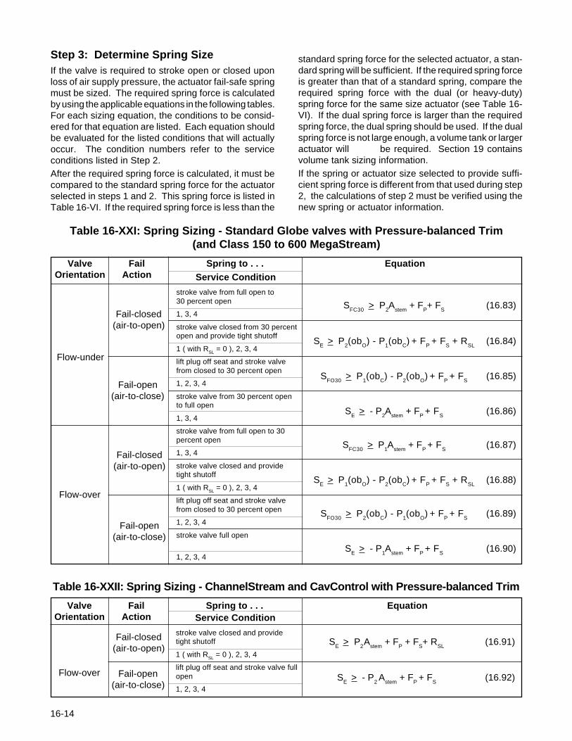
Step 3: Determine Spring SizeIf the valve is required to stroke open or closed uponloss of air supply pressure, the actuator fail-safe springmust be sized. The required spring force is calculatedby using the applicable equations in the following tables.For each sizing equation, the conditions to be consid-ered for that equation are listed. Each equation shouldbe evaluated for the listed conditions that will actuallyoccur. The condition numbers refer to the serviceconditions listed in Step 2.After the required spring force is calculated, it must becompared to the standard spring force for the actuatorselected in steps 1 and 2. This spring force is listed inTable 16-VI. If the required spring force is less than the
16-14
standard spring force for the selected actuator, a stadard spring will be sufficient. If the required spring foris greater than that of a standard spring, compare trequired spring force with the dual (or heavy-duspring force for the same size actuator (see Table 1VI). If the dual spring force is larger than the requirspring force, the dual spring should be used. If the duspring force is not large enough, a volume tank or largactuator will be required. Section 19 contavolume tank sizing information.If the spring or actuator size selected to provide sucient spring force is different from that used during st2, the calculations of step 2 must be verified using tnew spring or actuator information.
SFC30
> P2A
stem + F
P+ F
S(16.83)
SE > P
2(ob
O) - P
1(ob
C)
+ F
P + F
S + R
SL(16.84)
SFO30
> P1(ob
C) - P
2(ob
O)
+ F
P + F
S(16.85)
SE > - P
2A
stem + F
P + F
S(16.86)
SFC30
> P1A
stem + F
P + F
S(16.87)
SE > P
1(ob
O) - P
2(ob
C)
+ F
P + F
S + R
SL(16.88)
SFO30
> P2(ob
C) - P
1(ob
O)
+ F
P + F
S(16.89)
SE > - P
1A
stem + F
P + F
S(16.90)
stroke valve from full open to30 percent open
1, 3, 4
stroke valve closed from 30 percentopen and provide tight shutoff
1 ( with RSL = 0 ), 2, 3, 4
lift plug off seat and stroke valvefrom closed to 30 percent open
1, 2, 3, 4
stroke valve from 30 percent opento full open
1, 3, 4
stroke valve from full open to 30percent open
1, 3, 4
stroke valve closed and providetight shutoff
1 ( with RSL = 0 ), 2, 3, 4
lift plug off seat and stroke valvefrom closed to 30 percent open
1, 2, 3, 4
stroke valve full open
1, 2, 3, 4
Service Condition
Fail-closed(air-to-open)
Table 16-XXI: Spring Sizing - Standard Globe valves with Pressure-balanced Trim(and Class 150 to 600 MegaStream)
Valve Fail Spring to . . . EquationOrientation Action
Flow-under
Fail-open(air-to-close)
Fail-open(air-to-close)
Fail-closed(air-to-open)
Flow-over
Valve Fail Spring to . . . EquationOrientation Action
stroke valve closed and providetight shutoff
1 ( with RSL = 0 ), 2, 3, 4
lift plug off seat and stroke valve fullopen
1, 2, 3, 4
Service Condition
SE > P
2A
stem + F
P + F
S+ R
SL(16.91)
SE > - P
2 A
stem + F
P + F
S(16.92)
Fail-closed(air-to-open)
Flow-over
Table 16-XXII: Spring Sizing - ChannelStream and CavControl with Pressure-balanced Trim
Fail-open(air-to-close)

Table 16-XXIII: Spring Sizing - Tiger-Tooth and High Pressure MegaStream Valveswith Pressure-balanced Trim
Valve Fail Actuator to . . . EquationOrientation Action
SE > P
2(A
Sl - A
R) - P
1(A
Sl - A
R -
A
stem) + F
P + F
S(16.93)
SE > P
2(A
Sl - A
S) - P
1(A
Sl - A
S -
A
stem) + F
P + F
S + R
SL(16.94)
SR
> P1(A
Sl - A
S -
A
stem) - P
2(A
Sl - A
S) + F
P + F
S(16.95)
SE > P
1(A
Sl - A
R -
A
stem) - P
2(A
Sl - A
R) + F
P + F
S(16.96)
Fail-closed(air-to-open)
Fail-open(air-to-close)
Flow-under
Service Condition
lengths are given in Table XXVI. For the trims not listedin Table
Table 16-XXVGuardian II Actuator Pressure Limits
Valve ANSI Actuator Max. ActuatorSize Pressure Size Pressure
(inches) Class (sq. in.) (psig)
6 300 200 1006 300 300 608 150 200 1008 150 300 608 300 200 1008 300 300 60
XXVI, the stroke length is determined by comparing themaximum stroke length listed in Table XXIV to thestroke length of a standard Mark One valve that is thesame size and has the same trim. The actual strokelength of the valve with a Guardian II bellows seal will bethe shorter of these two stroke lengths.Fluid pressure inside the valve acts on the effectivebellows area. This area is listed in Table XXIV andshould be substituted for the actuator stem area in theactuator sizing equations.The relaxed position of the bellows is the distance fromthe seat where the bellows is not in tension or
IntroductionThe following data must be used when sizing actuatorsfor Guardian II metal bellows valves. This informationalong with the previous equations listed in Sizing andSelection section 16 will be combined for accuratesizing. See Table XXIV for the initial sizing informationneeded. While sizing, the actuator pressure limits inTable XXV must not be exceeded. For valve andactuator combinations not listed, the actuator pressurelimit is 150 psig.
Table 16-XXIV: Guardian II Bellows ValveActuator Sizing Information
Max. Effective Relaxed BellowsStroke Bellows Position SpringLength Area (in. from Rate
(inches) (sq. in.) seat) (lb/in)
1⁄2, 3⁄4, 1 150, 300 0.5 0.75 0 3611⁄2, 2 150, 300 1.0 1.35 0 26
3 150, 300 1.5 1.35 0.25 264, 6 150 2.5 2.38 0 154, 6 300 2.5 2.18 0 428 150 3.0 4.53 0 208 300 3.0 4.75 0 112
To determine actuator spring forces, the stroke lengthof a valve must be known. Many Guardian II stroke
Linear Actuator Sizing,Guardian II Metal Bellows Seal
Valve ANSISize Pressure
(inches) Class
stroke valve closed
1, 3, 4
provide tight shutoff
2, 3, 4
lift plug off seat
2, 3, 4
stroke valve full open
1, 3, 4
16-15

l
compression. The metal bellows acts as a spring thatis compressed or stretched as the plug is moved fromthe relaxed position. To account for the spring force ofthe bellows, it is necessary to add a term to the sizingequations of Section 16 of the Sizing & Selectionmanual. The term is added to the numerator on the rightside of the equations for actuator area and is added tothe right side of equations for spring force. This additionaterm is designated S
B. For equations used to determine
the actuator or spring size required to close the valve ,S
B is calculated by using Equation 1.
SB
= RB(P
R-P
A) (Equation 1)
For equations used to determine the actuator or springsize required to open the valve , S
B is calculated by
using Equation 2.
SB
= RB(P
A-P
R) (Equation 2)
Where:
SB
= Spring force of the metal bellows, lbs.
PA
= Actual position of the plug, in. (If theequation from Sizing & Selection section16 deter- mines the force required tomove the plug through arange of stroke values, use theposition that gives the largest value for S
B).
PR
= Relaxed position of the plug, in.(See Table XXIV).
RB
= Spring rate of the metal bellows, lb/in.(See Table XXIV).
16-16
Table 16-XXVI:Cv Data (=% Trim, Flow Over)
Valve Size Trim Stroke Full(inches) Number (inches) C v
1⁄2 .50 .50 4.2.31 .50 2.3
3⁄4 .72 .50 7.5.50 .50 5.4.31 .50 2.6
1 .81 .50 11.0.50 .50 5.7.31 .50 2.6
11⁄2 1.25 1.00 301.00 .75 22.81 .75 18
2 1.62 1.00 441.25 1.00 331.00 .75 23.81 .75 19
3 2.62 1.50 1071.62 1.50 49
4 3.50 2.50 2062.25 2.00 113
6 5.00 2.50 4053.50 2.50 236
8 6.25 3.00 6985.00 3.00 474
Table 16-XXVII: Examples of Modifications to Actuator Sizing Equations
Equation Modified Equation S B Equation S B Evaluation Position (P A)
16.9 1 30 percent open(0.3 X Stroke Length)
16.10 1 On seat(0.0 inches)
16.11 2 30 percent open(0.3 X Stroke Length)
16.12 2 Full open(Stroke Length)
16.31 1 30 percent open(0.3 X Stroke Length)
16.32 1 On seat(0.0 inches)
P1Abellows - SFC30 + FP + SBAU >
PS
P2A
S - P
1(A
S - A
bellows) - S
E + F
P + R
SL + S
BAU >
PS
P1 (A
S - A
bellows) - P
2A
S + S
FC30 + F
P +S
BAL >
PS
- P1A
bellows + S
R + F
P + S
BAL >
PS
SFC30
> P1A
bellows + F
P +S
B
SE
> P2A
S - P
1 (A
S - A
bellows) + F
P + R
SL + S
B

Rotary Actuator Sizing,Valdisk and Valdisk 150
IntroductionTo select an actuator for a Valdisk or Valdisk 150 highperformance butterfly valve, five sequential steps arenecessary:1. Determine the shaft orientation and actuator stiff-
ness requirements.2. Calculate the seating and breakout torque.3. Calculate the dynamic torque.4. Select an actuator capable of providing sufficient
torque to overcome the seating/breakout torqueand dynamic torque based on available air supply.
5. If a fail-open or fail-close action is required, selectan actuator capable of providing sufficient torque toovercome the seating/breakout torque and dy-namic torque based on available spring torque.
Step 1: Determine the Shaft OrientationBecause the disc in a Valdisk or Valdisk 150 is doubleoffset, when the shaft is oriented upstream the dynamictorque created by the process fluid will force the discinto the seat. A disc with the shaft oriented downstreamwill move toward the open position when near the seat.As a general rule, a valve that is required to fail-close onloss of instrument air supply usually has the shaftupstream. A valve which is required to fail open has theshaft downstream.
The above rule applies to all applications where theflowing fluid is a gas. On liquid applications with theshaft upstream, the actuator must be adequately stiff toprevent the disc from closing too rapidly, thus eliminat-ing any potential pressure surge condition which wouldresult in water hammer. To determine if the actuatorhas sufficient stiffness, calculate the following:
∆P (max)Actuator Stiffness (required) = (16.97) Sup. Press.
Compare the required actuator stiffness with the maxi-mum actuator stiffness values found in Table 16-XXVIII(according to valve size). Shaft upstream on a fail-closed liquid service can be used, provided the requiredstiffness does not exceed the actuator stiffness (max)for the actuator size selected. Note that in all cases thestandard actuator size for a given valve size is indicatedfirst in the chart. A larger actuator size may be requiredto ensure adequate stiffness. If the required stiffnessexceeds all those indicated for the actuator sizes avail-able for a given valve size, shaft downstream orienta-tion is required.
Step 2: Find the Seating and BreakoutTorqueUsing table 16-XXX and the following equations, calcu-late the seating and breakout torque.
Table 16-XXVIII: Actuator Stiffness (max.) for Shaft Upstream, Liquid Applications
Standard Standard Standard Standard Toggle-link Toggle-link25 50 100 200 100 200
2 3.13 3.14 1.7 8.86 0.81 4.3 6.9 15.98 2.4 6.0 13.8 13.2 30.4
10 1.3 3.4 7.8 7.5 17.212 2.4 5.5 5.3 12.114 1.4 3.2 3.1 7.016 0.98 2.2 2.16 4.818 0.84 1.9 1.85 4.220 0.53 1.2 1.17 2.624 0.39 0.87 .86 1.9
Actuator SizeValve Size(inches)
16-17
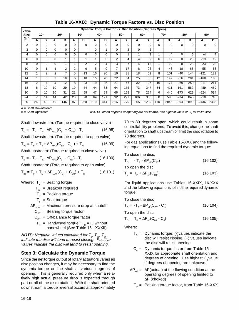
Table 16-XXIX: Dynamic Torque Factors vs. Disc PositionDynamic Torque Factor vs. Disc Position (Degrees Open)
10o 20o 30o 40o 50o 60o 70o 80o 90o
A B A B A B A B A B A B A B A B A B
2 0 0 0 0 0 0 0 0 0 0 0 0 0 0 0 0 0 0
3 0 0 0 0 0 0 1 0 2 0 2
4 0 0 0 0 0 0 0 0 0 1 1 2 1 4 0 6 -4 4
6 0 0 0 1 1 1 1 3 2 4 4 9 6 17 0 23 -19 19
8 0 0 0 1 1 2 2 4 3 7 4 12 1 19 -8 28 -23 23
10 0 1 1 2 2 6 5 9 7 17 8 28 4 46 -18 65 -55 55
12 1 2 2 7 5 13 10 20 16 38 18 61 8 101 -40 144 -121 121
14 1 3 3 10 6 18 15 28 22 54 25 85 12 142 -56 201 -168 168
16 2 4 4 12 8 23 19 36 27 67 32 106 15 177 -69 250 -211 211
18 5 10 10 29 19 54 44 83 64 156 73 247 34 411 -161 582 -489 489
20 5 10 10 31 21 58 47 89 68 168 78 264 6 440 -173 623 -524 524
24 7 14 14 42 28 78 64 121 92 227 106 358 50 596 -234 845 -710 710
30 24 49 49 146 97 268 219 414 316 779 365 1230 170 2046 -804 2899 -2436 2436
ValveSize(in.)
es of opening are not known, use highest value of Cd for valve size.
A = Shaft DownstreamB = Shaft Upstream NOTE: When degreShaft downstream: (Torque required to close valve)
Tst = - T
P - T
S - ∆P
MAX(C
BT + C
OT) - T
H (16.98)
Shaft downstream: (Torque required to open valve)
Tbo
= TP + T
S + ∆P
MAX(C
BT - C
OT) + T
H (16.99)
Shaft upstream: (Torque required to close valve)
Tst = - T
P - T
S - ∆P
MAX(C
BT - C
OT) - T
H (16.100)
Shaft upstream: (Torque required to open valve)
Tbo
= TP + T
S + ∆P
MAX(C
BT + C
OT) + T
H (16.101)
Where: Tst
= Seating torque
Tbo
= Breakout required
TP
= Packing torque
TS
= Seat torque
∆PMAX
= Maximum pressure drop at shutoff
CBT
= Bearing torque factor
COT
= Off-balance torque factor
TH
= Handwheel torque. TH = O without
handwheel (See Table 16 - XXXII)
NOTE: Negative values calculated for Tc, Tbo, Tst,indicate the disc will tend to resist closing. Positivevalues indicate the disc will tend to resist opening.
Step 3: Calculate the Dynamic TorqueSince the net torque output of rotary actuators varies asdisc position changes, it may be necessary to find thedynamic torque on the shaft at various degrees ofopening. This is generally required only when a rela-tively high actual pressure drop is expected throughpart or all of the disc rotation. With the shaft orienteddownstream a torque reversal occurs at approximately
16-18
70 to 80 degrees open, which could result in somecontrollability problems. To avoid this, change the shaftorientation to shaft upstream or limit the disc rotation to70 degrees.
For gas applications use Table 16-XXX and the follow-ing equations to find the required dynamic torque:
To close the disc:
TD = - T
P - ∆P
eff(C
BT) (16.102)
To open the disc:
TD = T
P + ∆P
eff(C
BT) (16.103)
For liquid applications use Tables 16-XXIX, 16-XXXand the following equations to find the required dynamictorque:
To close the disc
TD = -T
P - ∆P
eff(C
BT - C
d) (16.104)
To open the disc
TD = T
P + ∆P
eff(C
BT - C
d) (16.105)
Where:
TD = Dynamic torque: (-)values indicate thedisc will resist closing. (+) values indicatethe disc will resist opening.
Cd
= Dynamic torque factor from Table 16-XXIX for appropriate shaft orientation anddegrees of opening. Use highest C
d value
if degrees of opening are unknown.
∆Peff
= ∆P(actual) at the flowing condition at theoperating degrees of opening limited to∆P (choked)
TP
= Packing torque factor, from Table 16-XXX

Table 16-XXX: Static Breakout Torque = Sizing
TP = Packing Torque C BT = Bearing(in-lb) Torque Factor
(1) (2) (3) (4) (5) (6) (7)
2 150,300,600 50 280 477 350 63 74 0.09 0.13 0.203 50 280 477 350 63 154 0.20 0.30 0.404 57 333 533 399 71 270 0.48 0.72 0.716 64 385 590 448 81 596 1.27 1.90 1.668 79 490 702 543 104 980 2.73 4.10 2.5810 150,300* 79 490 702 543 104 1612 4.46 6.69 4.2512 104 648 870 691 151 2102 8.60 12.90 5.5514 150* 104 648 870 691 151 4338 11.98 17.97 25.6516 122 753 983 789 190 5853 16.61 24.92 34.6218 122 753 983 789 190 6639 21.99 32.99 39.2720 141 858 1095 886 234 9378 35.50 53.25 55.4224 141 858 1095 886 234 11829 44.78 67.17 65.4030 182 1068 1319 1081 342 19521 110.83 166.25 38.49
(1) TFE or filled TFE V-ring packing (5) Braided PTFE packing(2) Grafoil packing (6) Filament wound glass/TFE bearing(3) Twin Grafoil Packing (7) 316 stainless steel/solid film lubricant coated bearing and stellite bearings(4) Asbestos free packing * For higher pressure class data, consult factory
Valve ANSI T S = Seat COT = OffSize Pressure Torque Balance
(inches) Class (in-lb) Torque Factor
Actuator SpringSize Size
(sq.in.) 2 3 4 6 8 10 12 14 16 18 20 24 30
STD. 25 STD.
STD. 25 H.D.
STD. 50 STD.
STD. 50 H.D.
STD. 100 STD.
STD. 100 H.D.
STD. 200 STD.
STD. 200 H.D.
NOTE: For Valdisk valve compatibility with Toggle-link actuators, contact factory.
Valves Size (inches)
Table 16-XXXI: Valve/Actuator Compatibility - Valdisk/Valdisk 150
Table 16-XXXII:Declutchable Handwheel Torque (T H)
Actuator Size Handwheel Torque (sq.in.) (in-lbs)
25 150
50 250
100 - 200 375
16-19
CBT
= Bearing torque factor, from Table 16-XXX∆P(choked) is shown as:
∆P(choked) = FL2 (P
1 - F
fP
V)
(16.106)
Where:F
L= Valves recovery coefficient
P1
= Upstream pressure, psiaF
f= Liquid critical pressure ratio
PV
= Vapor pressure of the liquid, psia
Step 4: Determine Actuator Size BasedonAir SupplySelect an actuator from Table 16-XXXIII with sufficientnet torque to overcome the calculated seating/breakoutand dynamic torque through the full stroke rotation ofthe valve based on the available air supply.
After the actuator size has been selected, all gas andliquid applications with shaft downstream should bechecked for sufficient actuator stiffness. Using thefollowing equation, calculate corrected air supply:
SC = 0.867S
a - 12.3 (16.107)
Where: SC
= Corrected supply pressureS
a= Actual supply pressure
Using SC, consult Table 16-XXXIII and confirm that the
actuator size selected has sufficient torque to overcomethe dynamic torque values (calculated from step 3).Choose a larger actuator size if the torque availablethroughout the full stroke rotation is less than thedynamic torque calculated.
16-20
Finally, check the valve/actuator interface compatibilityin Table 16-XXXI for the actuator chosen.
Step 5: Select Actuator Based onAvailable Spring TorqueIf the spring must move the disc to a desired failureposition upon air supply loss, select an actuator fromtable 16-XXXIII according to the following criteria.(Available actuator sizes are indicated in Table 16-XXXI.)
For fail-closed valves, which do not require tight shutoffon air failure, the spring must provide sufficient torqueto overcome the calculated dynamic torque through thefull stroke rotation of the valve. For valves requiring tightshutoff, the spring must also provide sufficient torque atthe 0 degree (closed) position to overcome the requiredseating torque.
For fail-open valves, the spring must deliver sufficienttorque at the 90 degrees (closed) position to overcomethe calculated breakout torque. It must also havesufficient torque to overcome the dynamic torquethroughout the full stroke rotation of the valve.
Should the required torque be greater than the availablesprings can provide, a volume tank can be used toensure failure on loss of air supply.
For liquid applications with the shaft oriented upstream,the selected actuator should have adequate stiffness. Itshould also provide sufficient torque to overcome theseating/breakout torque and dynamic torque throughthe fall stroke rotation of the valve with the available airsupply and available spring torque, if a failure mode isrequired.

Degrees from Fail Position on Air Supply Loss
0 10 20 30 40 50 60 70 80 90
STD 25 with 150 3013 3399 3700 3907 4000 3970 3811 3514 3084 2532STD Spring 140 2755 3165 3444 3631 3714 3685 3531 3253 2854 2339
120 2397 2695 2928 3080 3145 3110 2972 2731 2390 1962100 1986 2228 2412 2530 2573 2535 2414 2211 1928 157780 1574 1759 1896 1979 2002 1961 1856 1688 1463 119160 1163 1290 1381 1428 1430 1386 1298 1167 1001 80640 751 821 864 876 858 811 738 645 537 420
Spring Torque 54 86 125 169 213 254 284 299 293 262
STD 25 with 150 2647 2973 3223 3386 3448 3403 3246 2976 2600 2124HD Spring 140 2441 2738 2964 3110 3162 3115 2966 2716 2368 1931
120 2030 2270 2450 2558 2590 2542 2409 2195 1905 1552100 1618 1802 1934 2009 2020 1967 1850 1673 1441 116780 1206 1333 1418 1457 1448 1392 1292 1151 978 78160 795 865 902 907 877 818 733 630 515 396
Spring Torque 440 542 647 749 839 908 945 937 878 758
STD 50 with 150 10701 11981 13015 13751 14134 14089 13575 12568 11043 9035STD Spring 140 9970 11157 12114 12798 13136 13083 12596 11653 10232 8365
120 8516 9513 10318 10874 11141 11075 10649 9826 8615 7053100 7059 7873 8515 8953 9153 9073 8693 7999 6995 571280 5602 6227 6716 7033 7156 7062 6736 6174 5372 437360 4147 4586 4913 5114 5166 5058 4784 4347 3755 303440 2690 2942 3111 3192 3171 3049 2829 2519 2134 1693
Spring Torque 222 343 489 651 816 966 1081 1134 1107 983
STD 50 with 150 9774 10898 11781 12380 12651 12533 12000 11036 9648 7850HD Spring 140 9044 10074 10880 11425 11652 11527 11021 10122 8837 7183
120 7591 8430 9083 9502 9657 9519 9073 8300 7216 5865100 6133 6790 7281 7585 7668 7516 7117 6473 5597 452780 4678 5148 5481 5660 5671 5508 5163 4646 3974 318660 3223 3505 3681 3741 3680 3501 3209 2821 2356 1846
Spring Torque 1148 1428 1726 2026 2304 2529 2662 2667 2511 2167
STD 100 with 150 26194 29415 32022 33847 34730 34559 33234 30711 26943 22035STD Spring 140 24385 27397 29784 31459 32253 32069 30831 28446 26936 20378
120 20805 23329 25330 26685 27303 27104 25983 23921 20932 17119100 17226 19271 20859 21914 22368 22119 21134 19394 16920 1380880 13640 15200 16399 17153 17413 17133 16296 14878 12915 1048560 10055 11139 11929 12391 12472 12159 11447 10350 8901 716740 6469 7077 7472 7624 7526 7181 6605 5829 4893 3851
Spring Torque 704 1049 1461 1913 2370 2783 3088 3225 3135 2775
STD 100 with 150 24678 27231 29008 29925 29917 28969 27058 24266 20699 16483HD Spring 140 22881 25195 26771 27539 27459 26475 24632 22001 18691 14832
120 19304 21127 22317 22784 22507 21490 19782 17472 14680 11563100 15713 17070 17847 18012 17567 16518 14946 12956 10674 824580 12130 12999 13385 13248 12612 11538 10101 8432 6662 492760 8545 8939 8921 8483 7673 6558 5257 3910 2662 1611
Spring Torque 2217 3256 4485 5831 7185 8405 9299 9691 9407 8316
STD 200 with 80 27695 31132 33903 35838 36820 36663 35280 32620 28633 23416STD Spring 70 24156 27119 29480 31134 31916 31730 30501 28139 25670 20206
60 20595 23091 25069 26406 27014 26813 25699 24656 20697 1692650 17051 19072 20643 21696 22126 21876 20897 19173 16724 1364640 13501 15043 16227 16969 17223 16952 16109 14703 12760 1035730 9951 11022 11808 12253 12328 12015 11307 10219 8785 7071
Spring Torque 704 1049 1461 1913 2370 2783 3088 3225 3135 2775
STD 200 with 80 26192 28930 30894 31940 32005 31052 29104 26177 22393 17887HD Spring 70 22636 24918 26467 27214 27122 26136 24302 21693 18420 14650
60 19094 20889 22056 22505 22217 21198 19499 17208 14445 1137050 15538 16872 17629 17779 17326 16275 14709 12735 10478 808340 11991 12842 13212 13064 12421 11346 9914 8257 6507 479930 8441 8821 8792 8345 7530 6414 5116 3778 2536 1514
Spring Torque 2217 3256 4485 5831 7185 8405 9299 9691 9407 8316
NOTE: For air-to-open/fail-closed actuators the 0 degree position shown corresponds to the disc or ball being seated.For air-to-close/fail-open actuators the 90 degree position shown corresponds to the disc or ball being seated.
Actuaor SupplySize Pressure
(continued)
Table 16-XXXIII: Net Torque Output of Standard Actuators at Various Supply Pressures (in-lb)
16-21

Degrees from Fail Position on Air Supply Loss
0 10 20 30 40 50 60 70 80 90
STD 100 with 150 55253 50511 48414 47688 47565 47596 47231 46243 44044 40216No Spring 140 51566 47141 45183 44506 44390 44417 44077 43155 41094 37629
120 44200 40407 38730 38149 38050 38072 37781 36991 35224 32255100 36835 33674 32276 31792 31709 31728 31486 30827 29357 2689180 29465 26937 25818 25431 25365 25380 25185 24659 23482 2150470 25783 23570 22591 22252 22195 22208 22038 21577 20548 1882160 22100 20203 19364 19074 19024 19035 18889 18494 17611 16126
STD 100 with 150 46475 41517 39053 37762 37004 36347 35492 34086 31885 28585STD 20" Spring 140 42763 38174 35847 34581 33832 33173 32336 30996 28927 25968
120 35341 31457 29418 28256 27519 26856 26033 24847 23070 20597100 27996 24741 22967 21923 21185 20532 19745 18676 17192 1521980 20640 18023 16531 15583 14860 14190 13447 12513 11320 984270 16973 14671 13318 12409 11702 11029 10295 9427 8381 715660 13303 11309 10103 9244 8536 7866 7149 6348 5447 4469
Spring Torque 8764 8854 9234 9802 10469 11161 11775 12185 12209 11625
STD 100 with 150 42482 37897 35540 34250 33432 32745 31840 30466 28395 25370HD 28" Spring 140 38800 34552 32330 31070 30261 29572 28686 27398 25457 22747
120 31452 27836 25881 24741 23946 23233 22399 21227 19580 17376100 24099 21123 19447 18393 17627 16909 16095 15068 13712 1199780 16745 14404 13009 12063 11299 10577 9798 8900 7836 662070 13077 11049 9794 8889 8139 7414 6652 5815 4900 393060 9405 7687 6576 5722 4976 4249 3506 2735 1962 1242
Spring Torque 12677 12491 12773 13330 14038 14783 15436 15804 15699 14847
STD 200 with 120 90138 82403 78982 77799 77597 77646 77052 75440 71847 65573No Spring 100 75117 68671 65820 64834 64666 64705 64210 62867 59870 54840
80 60092 54935 52655 51865 51731 51761 51365 50291 47891 4385770 52580 48067 46072 45381 45263 45291 44944 44004 41906 3838460 45067 41199 39489 38897 38796 38819 38521 37716 35915 3288750 37558 34335 32910 32416 32332 32352 32104 31433 29934 2741940 30046 27467 26327 25932 25864 25880 25682 25144 23944 21928
STD 200 with 120 81372 73545 69667 67776 66960 66341 65317 63265 59683 53947STD 20" Spring 100 66376 59778 56415 54835 54063 53409 52467 50725 47718 43167
80 51346 45950 43301 41931 41139 40508 39606 38139 35730 3219470 43764 39076 36736 35455 34705 34045 33203 31846 29737 2672060 36215 32250 30176 29000 28245 27602 26775 25573 23761 2122950 28722 25402 23601 22546 21806 21140 20364 19282 17770 1575840 21221 18554 17039 16083 15359 14689 13944 12999 11784 10272
Spring Torque 8764 8854 9234 9802 10469 11161 11775 12185 12209 11625
STD 200 with 120 77455 69905 66066 64242 63370 62710 61663 59644 56196 50755HD 28" Spring 100 62436 56083 52894 51326 50491 49816 48813 47105 44228 39946
80 47376 42304 39777 38398 37592 36886 35982 34519 32240 2897270 39792 35474 33196 31945 31133 30444 29554 28247 26266 2348160 32321 28628 26640 25488 24692 23979 23141 21953 20271 1800750 24823 21783 20081 19016 18249 17532 16714 15675 14290 1252540 17326 14934 13517 12555 11798 11077 10294 9380 8299 7043
Spring Torque 12677 12491 12773 13330 14038 14783 15436 15804 15699 14847
STD 200 with 120 74734 67370 63658 61889 60983 60326 59298 57364 53986 48740HD 34" Spring 100 59697 53551 50490 48931 46106 47431 46441 44783 42018 37928
80 44588 39793 37353 36033 35208 34501 33610 32197 30030 2695370 37026 32944 30791 29558 28770 28059 27182 25926 24055 2146260 29543 26095 24212 23099 22310 21609 20769 19632 18059 1597750 22050 19252 17655 16641 15866 15148 14353 13353 12078 1050540 14567 12404 11099 10175 9416 8698 7929 7065 6087 5019
Spring Torque 15446 15021 15198 15718 16422 17180 17808 18127 17921 16866
Actuaor SupplySize Pressure
Table 16-XXXIII: (continued)Net Torque Output of Toggle-link Actuators at Various Supply Press. (in-lb)
NOTE: For air-to-open/fail-closed actuators the 0 degree position shown corresponds to the disc or ball being seated.For air-to-close/fail-open actuators the 90 degree position shown corresponds to the disc or ball being seated.
16-22

Rotary Actuator Sizing,ShearStream
Introduction
To select an actuator for a ShearStream high perform-ance ball valve, three steps are necessary:
1. Determine seating/breakout torques. (Also deter-mine the dynamic torque in liquid applications.)
2. Select an actuator capable of providing sufficienttorque to overcome the seating/breakout torqueand dynamic torque based on available air supply.
3. If a failure action is required, select an actuatorcapable of providing sufficient torque to overcomethe seating/breakout torque and dynamic torquebased on available spring torque.
Step 1: Determine Seating/BreakoutTorques.
Normally, ShearStream valves are installed with theshaft downstream. However, in an erosive service thevalve should be installed with the shaft upstream. Withthe shaft upstream, erosive action will occur in theretainer and not the ball surface or the valve body. Todetermine the seating/breakout torque, use equation(16.108) or (16.109), according to the application.
For shaft downstream, seating/breakout torque isshown as:
Tbo
= TP + T
S + ∆P
max (C
B + C
s) + T
H(16.108)
For shaft upstream, seating/breakout torque is shownas:
Tbo
= TP + T
S + ∆P
max (C
B) + A + T
H(16.109)
NOTE: A = (TS - ∆P(CS). If A is less than zero, enter zerofor A.
In liquid service applications, the dynamic torque mustalso be determined. Actuator sizing is based on theseating/breakout torque and dynamic torque. To deter-mine dynamic torque, use the following equation:
TD = T
P + ∆P
eff(C
D + C
B) (16.110)
Where:T
bo= Seating/breakout torque (in-lb) is the torque
required to close and open the valve.
TP
= Packing torque (in-lb) is the torque required toovercome the friction of the packing on theshaft. Packing torque varies with packingmaterial. (See Table 16-XXXVI)
TS
= Seat torque (in-lb) is the torque required toovercome the friction of the seat on the ball.(See Table 16-XXXVI)
∆Pmax
= Pressure drop (lb/in2) across the valve whenvalve is in the closed position.
TD
= Dynamic torque (in-lb) is the torque requiredto overcome the torque on the closure mem-ber caused by the fluid-dynamic forces on theball.
∆Peff
= Actual pressure drop (lb/in2) across the valveat the flowing condition which occurs whenthe valve is in an open position. ∆P
eff is less
than or equal to ∆P(choked).
∆Pchoked
= FL
2(P1 - F
fP
V) (16.111)
Where: FL
= Valve recovery coefficient(See Table 16-XXXIV)
P1
= Upstream pressure, psia
Ff
= Liquid critical pressure ratio
Pv
= Vapor pressure of liquid, psia
CB
= Bearing torque factor (in3). As the pressureacross the valve increases, the force on thebearings increases proportionally.
CB(∆P) = bearing torque (in-lb).
(See Table 16-XXXVI)
CS
= Seat torque factor (in3). As the pressureacross the valve increases, the force at whichthe seat pushes into the ball increases (shaftdownstream) or decreases (shaft upstream).(See Table 16-XXXVI)
CD
= Dynamic torque factor. (See Table 16-XXXVI)
TH
= Handwheel torque. TH = 0 without handwheel
(See Table 16-XXXII)
16-23

Percent of ApproximateRated C V FL
10 .9020 .8530 .8240 .7850 .7360 .6870 .6580 .6390 .62
100 .60
Table 16-XXXIV:Approximate F L
16-24
Actuator Spring Valve/ActuatorSize Size Compatibility
(in 2) Valve Size (inches)
1 1.5 2 3 4 6 8 10 12STD. 25 STD.
STD. 25 H.D.
STD. 50 STD.
STD. 50 H.D.
STD. 100 STD.
STD. 100 H.D.
STD. 200 STD.
STD. 200 H.D.
Table 16 - XXXV:Valve/Actuator Compatibility - ShearStream
Table 16-XXXVI: ShearStream Static Torques - Sizing
Valve TP=Packing Torque T S=Seat CB=Bearing C S=Seat CD = DynamicSize (in-lb) Torque Torque Factor Torque Factor Torque Factor
(in.) (1) (2) (3) (4) (5) (in-lb) (6) (7) 60 O 90O
1 43 228 421 301 57 20 0.06 0.09 0.1 0.25 0.611/2 50 280 477 350 63 40 0.06 0.09 0.1 0.5 1.0
2 50 280 477 350 63 60 0.06 0.09 0.15 1.0 2.1 3 57 333 533 399 71 150 0.19 0.28 0.42 4.5 8.0 4 57 333 533 399 71 360 0.38 0.58 0.82 10.0 17.0 6 71 438 646 496 92 540 0.97 1.45 1.64 19.5 30.5 8 71 438 646 496 92 670 1.58 2.37 2.62 52.0 75.510 104 648 870 691 151 1100 4.38 6.57 4.55 108.0 165.512 104 648 870 691 151 1300 5.61 8.41 6.05 191.0 218.5
(1) TFE or filled TFE V-ring packing(2) Grafoil(3) Twin Grafoil(4) Asbestos-free packing (AFP)
(5) Braided PTFE(6) TFE lined bearings(7) Metal bearings