Embed Size (px)
Citation preview


INTRODUCTION
GENERAL DESCRIPTION
McQuay type ALP SEASONCON air cooled condensing unitsare designed for outdoor installations and are compatible witheither air handling or chilled water systems. Each unit is com-pletely assembled and factory wired before evacuation, charg-ing and testing, and comes complete and ready for installa-tion. Each unit consists of twin air cooled condensers withintegral subcooler sections, multiple accessible hermetic com-pressors, complete discharge piping and suction connectionsfor connection to any air or water cooling evaporator.
The electrical control center includes all safety andoperating controls necessary for dependable automaticoperation except for the cooling thermostat since this issomewhat dependent on the unit application. Condenser fanmotors are fused in all three conductor legs and started bytheir own three-pole contactors. Compressors are not fusedbut may be protected by optional circuit breakers, or by fieldinstalled fused disconnect.
NOMENCLATURE
A L P - 080 C
T CESIGN ;/II’-~‘h*:,.;r
NOMINAL CAPACITY (TONS)
INSPECTION
When the equipment is received, all items should be carefully be checked before unloading the unit t o ba sure that it agreeschecked against the bill of lading to insure a complete ship- with the power supply available. Physical damage to unit afterment. All units should be carefully inspected for damage upon acceptance is not the responsibility of McQuay.arrival. All shipping damage should be reported to the car- NOTE: Unit shipping and operating weights are availablerier and a claim should be filed. The unit serial plate should in the physical data tables on pages 10 and 1 1.
INSTALLATIONNOTE: Installation and maintenance are to be performed only by qualified personnel who are familiar with local codesand regulations, and experienced with this type of equipment. CAUTION: Sharp edges and coil surfaces are a potentialinjury hazard. Avoid contact with them.
HANDLING
Care should be taken to avoid rough handling or shock dueto dropping the unit. Do not push or puli the unit from anythingother than the base, and block the pushing vehicle away fromthe unit to prevent damage to the sheetmetal cabinet and endframe (see Figure 1).
Never allow any part of the unit to fall during unloading or
Figure 1. Suggested Pushing Arrangement
BLOCKING REQ’D.ACROSS FULL WIDTH
I i n
moving as this may result in serious damage.To lift the unit, 2%” diameter lifting holes are provided in
the base of the unit. Spreader bars and cables should be ar-ranged to prevent damage to the condenser coils or unitcabinet (see Figure 2).
Figure 2. Suggested Lifting Arrangement
IM 269 I Page 3

LOCATION
Care should be taken in the location of the unit to provide Minimum clearances as shown in Figure 3 will prevent mostproper airflow to the condenser, minimizing effects on con- discharge air recirculation to the condenser which will havedensing pressure. a significant effect on unit performance.
SERVICE ACCESS
Each end of the unit must be accessible after installation forperiodic service work. Compressors, filter-driers, and manualliquid line shutoff valves are accessible on each side of theunit adjacent to the control box. High pressure, low pressure,and motor protector controls are on the compressor. Mostother operational, safety and starting controls are located inthe unit control box.
On all ALP units the condenser fans and motors can beremoved from the top of the unit. A complete fan/motorassembly should be removed for service.
CAUTION: Disconnect all power to unit while servicing con-denser fan motors.
Figure 3. Clearance Requirements ALP-045C thru 230C
6 FT. MIN. CLEARANCEFOR AIR INLET
(1) Minimum clearance between units is 12 feet.(2) Units must not be Installed in a pit that is deeper than the height of the unit.(3) Minimum clearance on each side is 12 feet when installed in a pit.
6 FT. MIN. CLEARANCEFOR AIR INLET
VIBRATION ISOLATORSVibration isolators are recommended for all roof mounted in-stallations or wherever vibration transmission is a considera-tion. Table 1 lists spring isolators for all ALP unit sizes. Figure4 shows isolator locations in relation to the unit control center.Figure 5 gives dimensions that are required to secure each
Table 1. Vibration Isolators (Spring)
Q?txJ CPl-31 CPl-31 CPl-27 CPl-31 CPl-31 CPl-27ioU@ CPl-32 CPl-32 CPl-28 CPl-32 CPl-32 CPl-28OS@ CPl-32 CPl-32 CPl-28 CPl-32 CPl-32 CPl-28low CPl-32 CPl-32 CPl-28 CPl-32 CPl-32 CPl-28
?8W: CP2-28 CP2-26 CP2-28 CP2-26 CP2-28 CP2-28Z96Q CP2-31 CP2-31 CP2-31 CP2-31 CP2-31 CP2-31OgoC CP2-31 CP2-31 CP2-31 CP2-31 CP2-31 CP2-31
McQuay isolator selection to the mounting surface. Table 3shows the isolator loads at each location shown in Figure 4,and the maximum loads for each McQuay selection areshown in Table 2.
Table 2. Spring-flex Isolators
Gray W/2 White Stripes
Gray W/Orange Stripe
Gray W/Green StripeGray W/2 Yellow Stripes
477927A-26 600477927A-27 750477927A-26 900477927A-31 1100
Page 4 / IM 269


REFRIGERANT PIPING
GENERALPiping design, sizing and installation information presentedin ASHRAE Handbooks should, where applicable, be followedin the design and installation of piping. McQuay type ALPcondensing units are adaptable to either chilled water or airhandling air conditioning applications. The only restriction onapplications is that the evaporator be selected for a systemusing refrigerant R-22.
REFRIGERANT PIPINGPiping between the condensing unit and the cooling coil mustbe designed and installed to minimize pressure drop, pre-vent liquid refrigerant carryover to the compressor and toassure a continuous return of compressor oil from the system.Piping sketches and tables are not intended to provide infor-mation on all of the possible arrangements. For example,when dual circuit evaporators are used with an unloadingcompressor, two liquid line solenoid valves may be used toreduce coil capacity with compressor unloading. Noteespecially that dual circuit evaporators should not be pipedwith common liquid and suction lines to more than one com-pressor circuit. Separate evaporators, evaporator circuits andpiping must be run for each compressor circuit.
Piping recommendations include:1. The use of type K or L clean copper tubing. All ioints should
be thoroughly cleaned and brazed with high temperaturesolder.Piping sizes should be based on temperature/pressurelimitations as recommended in the following paragraphs.Under no circumstances should pipe size be based uponthe coil or condensing unit piping connection size.Suction line piping pressure drop should not exceed thepressure equivalent of 2” F (3 psi) per 100 feet of equivalentpipe length. After the suction line size has been deter-mined, the vertical suction risers should be checked toverify that oil will be carried up the riser and back to thecompressor. The suction line(s) should be pitched in thedirection of refrigerant flow and adequately supported.Lines should be free draining and fully insulated betweenthe evaporator(s) and the compressor. Table 7, page 8,shows piping information for units operating at suctiontemperatures between 40” F and 45” F and a condenserentering air temperature of 95” F. If operating conditionsare expected to vary substantially from these operatinglevels, the pipe sizing should be rechecked.Vertical suction risers should be checked using Table 5to determine the minimum tonnage required to carry oilup suction risers of various sizes.The liquid line should be sized for a pressure drop not toexceed the pressure equivalent of 2°F (6 psi) saturatedtemperature. The liquid line(s) on all units must include
a liquid solenoid valve wired into the circuit as shown onthe applicable unit wiring diagrams.
The control circuit for all compressors has been de-signed to include a pumpdown cycle. The use of a liquidline solenoid is required for proper unit operation. In ad-dition, a filter-drier should be located between the liquidline service valve and the solenoid valve and a combina-tion moisture indicator/sightglass should be located in theliquid line ahead of the expansion valve.Suggested piping arrangements are shown on page 7. Allmultiple compressor units require a separate refrigerantcircuit for each compressor. The figures shown are for anair handling installation, but all components shown arerecommended for chilled water vessel installations exceptthat a refrigerant distributor is not usually required for shell-and-tube evaporators.If dual suction risers are used:
Double risers are sized so that their combined cross-sectional internal area will allow full load unit operationwithout excessive pressure drop (see notes, Table 7). Riser“A” is sized to provide adequate suction gas velocity forproper oil return at minimum load conditions. This riserbecomes effective only when the trap shown in riser “B”fills itself with oil. It should be emphasized that the trapshown in riser “B” should be designed to contain aminimum internal volume to keep the total system oil re-quirements at a minimum. Table 7 gives recommendedline sizes for both single and double suction lines and forliquid lines.
The combined cross-sectional areas of the two risersmust be capable of maintaining adequate refrigerantvelocity for oil return at full unit tonnage.The extra riser should be of a smaller diameter thanthe main riser. The extra riser must include its own trapat the bottom and should enter the main suction headerat twelve o’clock.The trap serving the extra riser must be as short as fit-tings permit. A “U” fitting or the combination of a 90”standard "L" and a 90” street-l is recommended.The suction line leaving the coil should also include atrap if the expansion valve control bulb is to be on thehorizontal section leaving the coil outlet. See the pip-ing sketches on page 7.
Table 5. Minimum tonnage (R-22) to carry oil upsuction riser at 40 o F saturated suction.
NOTE: When compressor minimum tonnage is less than shown in the abovetable for a given line size, double suction risers will be required.
Table 6. Equivalent feet of straight tubing for copper fittings and valves
Page 6 I IM 269

Figure 6. SINGLE CIRCUIT EVAPORATOR - RECOMMENDED PIPINGIf Row Split Coils Are Used, Duplicate The Piping
CONDENSING UNIT ABOVE THE EVAPORATOR CONDENSING UNIT BELOW THE EVAPORATOR
Figure 7. DUAL CIRCUIT EVAPORATOR (FACE SPLIT) - RECOMMENDED PIPING
_d”
\ _,D”Ai RISER L -.- 1 ~~ iVP4NSlON Lla.,vt ;:
CONTROL BULBSSUCTION TRAP
L FXPANSlOlv VALVE‘S~FIPIV TO LlNt
\.__ _--
SHORT AS$1 ! -,m .R‘iP - TONTROL BLLRS
--i’ “IUD INSULnrEFITTINGS PERMIT
SMORT *s STRAP TO LlhEF TT,rvi,S PFPMll 4ND US”L4TE
NOTES:1. Piping shown is for one compressor circuit; second circuit is similar. Must have separate piping for each compressor circuit.2. Trap for double suction riser should be as small in horizontal direction as fittings will allow.3. The thermal expansion valve equalizer line should be placed just past the thermal sensing bulb on the side or top of the pipe.4. A separate expansion valve is required for each distributor and mounted per manufacturer’s recommendations.
(See additional notes under recommended line sizes, Table 7.)
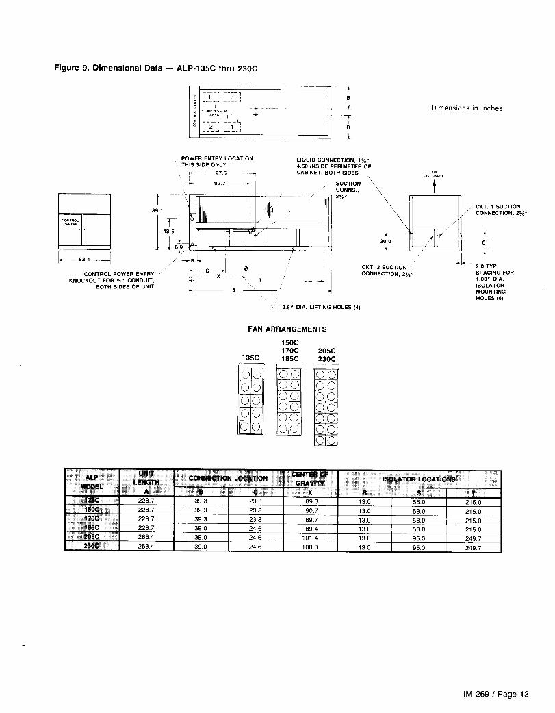
REFRIGERANT PIPING CONNECTIONSRefrigerant piping connections will be made at the com- unit. When piping, allow room for the unit disconnect and fieldpressor end of the unit. Suction and liquid lines should be wiring to the unit. Figures 8 and 9 show piping connectionsrouted through the compressor enclosure on each side of the and sizes for each ALP model.
IM 269 / Page 7
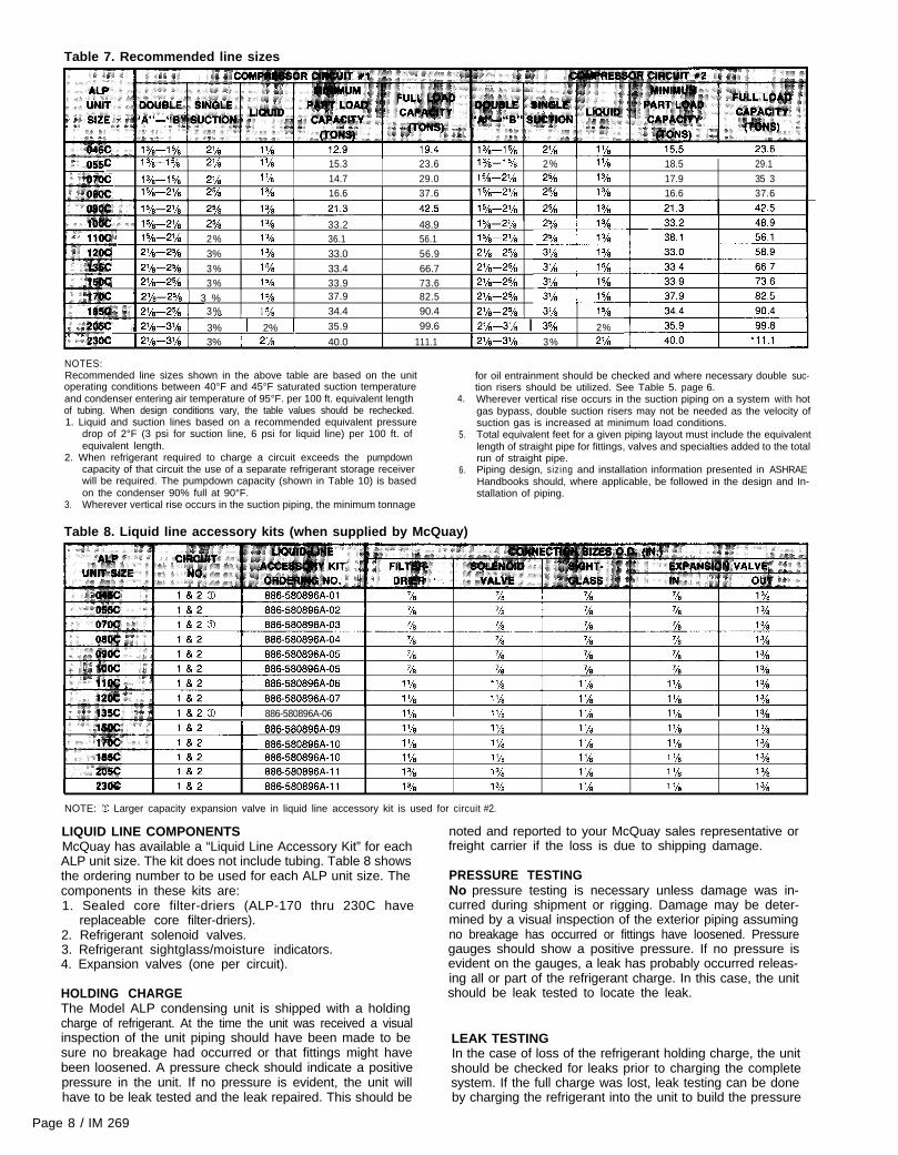
Table 7. Recommended line sizes
c 1 vi-1 5/a 2% 1% 15.3 23.6 IYe- % 2% 1 ‘/s 18.5 29.1
14.7 29.0 t 17.9 35 31%--15/g a!¶ 1 ‘/a t 5/8-2’/8 25/n %15/s--2’h 2% 1% 16.6 37.6 15h--2’h 2% 1 YE 16.6 37.6
1% 33.2 48.9 t %-2’/a1%-2% 2% 1% 36.1 56.1 t5/8-2’/!
I$ 2%-25/s 3% 1% 33.0 56.9 2’/8-2%
irr: .%-25/n 3% 1% 33.4 66.7 2’%-2%tc I 2%-25/n I 3% t % 33.9 73.6 2%-25/e
E f 2%-25/e I 3 % 1% 37.9 82.5 2%-25/s3% 1 =/n 34.4 90.4 2%-25/a~,I , II , .” ._ , 3’/a 1%
C 3% I 2% I 35.9 99.6 1 2+-31/s I 35/s 2%w 1 Wi-3% 1 3% 1 2% 1 40.0 111.1 1 Wi-3% 1 3% 2%
NOTES:Recommended line sizes shown in the above table are based on the unit for oil entrainment should be checked and where necessary double suc-operating conditions between 40°F and 45°F saturated suction temperature tion risers should be utilized. See Table 5. page 6.and condenser entering air temperature of 95°F. per 100 ft. equivalent lengthof tubing. When design conditions vary, the table values should be rechecked.1. Liquid and suction lines based on a recommended equivalent pressure
drop of 2°F (3 psi for suction line, 6 psi for liquid line) per 100 ft. ofequivalent length.
4.
5.
2. When refrigerant required to charge a circuit exceeds the pumpdowncapacity of that circuit the use of a separate refrigerant storage receiverwill be required. The pumpdown capacity (shown in Table 10) is basedon the condenser 90% full at 90°F.
3. Wherever vertical rise occurs in the suction piping, the minimum tonnage
6.
Table 8. Liquid line accessory kits (when supplied by McQuay)
Wherever vertical rise occurs in the suction piping on a system with hotgas bypass, double suction risers may not be needed as the velocity ofsuction gas is increased at minimum load conditions.Total equivalent feet for a given piping layout must include the equivalentlength of straight pipe for fittings, valves and specialties added to the totalrun of straight pipe.Piping design, sizing and installation information presented in ASHRAEHandbooks should, where applicable, be followed in the design and In-stallation of piping.
886-580896A-06 .” ,”i 886~580896A-09 1% 1 ‘/a
886~580896A-10 1 ‘/s 1 ‘/sl&2 886-580896A-10 1% l’/al&2 886-580896A-11 1% 1%
I 23oc 182 886~580896A-11 1% 1%
NOTE: % Larger capacity expansion valve in liquid line accessory kit is used for circuit #2.
,- ,_ ._1 ‘/a 1 ‘/a 1 Yi1 ‘h 1 ‘/a 1%1 ‘h 1 ‘/a 1%1% 1 ‘h 1%t ‘/s 1 ‘/a 1%
LIQUID LINE COMPONENTSMcQuay has available a “Liquid Line Accessory Kit” for eachALP unit size. The kit does not include tubing. Table 8 showsthe ordering number to be used for each ALP unit size. Thecomponents in these kits are:1. Sealed core filter-driers (ALP-170 thru 230C have
replaceable core filter-driers).2. Refrigerant solenoid valves.3. Refrigerant sightglass/moisture indicators.4. Expansion valves (one per circuit).
HOLDING CHARGEThe Model ALP condensing unit is shipped with a holdingcharge of refrigerant. At the time the unit was received a visualinspection of the unit piping should have been made to besure no breakage had occurred or that fittings might havebeen loosened. A pressure check should indicate a positivepressure in the unit. If no pressure is evident, the unit willhave to be leak tested and the leak repaired. This should be
Page 8 / IM 269
noted and reported to your McQuay sales representative orfreight carrier if the loss is due to shipping damage.
PRESSURE TESTINGNo pressure testing is necessary unless damage was in-curred during shipment or rigging. Damage may be deter-mined by a visual inspection of the exterior piping assumingno breakage has occurred or fittings have loosened. Pressuregauges should show a positive pressure. If no pressure isevident on the gauges, a leak has probably occurred releas-ing all or part of the refrigerant charge. In this case, the unitshould be leak tested to locate the leak.
LEAK TESTINGIn the case of loss of the refrigerant holding charge, the unitshould be checked for leaks prior to charging the completesystem. If the full charge was lost, leak testing can be doneby charging the refrigerant into the unit to build the pressure
to approximately 10 psig and adding sufficient dry nitrogento bring the pressure to a maximum of 125 psig. The unitshould then be leak tested with a Halide or electronic leakdetector. After making any necessary repair, the systemshould be evacuated as described in the followingparagraphs.
CAUTION: Do not use oxygen to build up pressure. Aserious explosion could be the result.
EVACUATIONAfter it has been determined that the unit is tight and thereare no refrigerant leaks, the system should be evacuated.The use of a vacuum pump with a pumping capacity of ap-proximately 3 cu. ft./min. and the ability to reduce the vacuumin the unit to at least 1 millimeter (1000 microns) is recom-mended.
The first pull down will remove about 90% of the non-condensibles, the second about 90% of that remainingfrom the first pull down and after the third only 1 /1 0 of 1 o/o
non-condensibles will remain.Table 12, page 10, shows the relationship between pressure,microns, atmospheres, and the boiling point of water.
A mercury manometer, electronic or other type of microngauge should be connected to the unit at a point remotefrom the vacuum pump. For readings below 1 millimeter,an electronic or other micron gauge should be used.The triple evacuation method is recommended and is par-ticularly helpful if the vacuum pump is unable to obtainthe desired 1 millimeter of vacuum. The system is firstevacuated to approximately 29 inches of mercury. Enoughrefrigerant vapor is then added to the system to bring thepressure up to 0 pounds.Then the system is once again evacuated to 29 inchesof vacuum. This procedure is repeated three times. Thismethod can be most effective by holding system pressureat 0 pounds for a minimum of 1 hour between evacuations.
CHARGING THE SYSTEMModel ALP condensing units are leak tested at the factoryand shipped with a holding charge of refrigerant. In the eventthe refrigerant charge has been lost due to shipping damage,the system should be charged with enough refrigerant to raisethe unit pressure to 30 psig after first repairing the leaks andevacuating the svstem.
After all refrigerant piping is complete and the system hasbeen evacuated, it can be charged as described in theparagraphs following. Connect the refrigerant drum to thegauge port on the liquid shutoff valve and purge the charg-ing line between the refrigerant cylinder and the valve.Then open the valve to the mid-position.If the system is under a vacuum, stand the refrigerant drumwith the connection up and open the drum and break thevacuum with refrigerant gas.With a system gas pressure higher than the equivalentof a freezing temperature, invert the charging cylinder andelevate the drum above the condenser. With the drum inthis position, valves open and liquid refrigerant will flowinto the condenser. Approximately 75% of the total require-ment estimated for the unit can be charged in this manner.After 75% of the required charge has entered the con-denser, reconnect the refrigerant drum and charging lineto the suction side of the system. Again purge the con-necting line, stand the drum with the connection up, andplace the service valve in the open position.
IMPORTANT: At this point charging procedure should beinterrupted and prestart checks made before attempting tocomplete the refrigerant charge. See startup procedures onpage 48.
NOTE: It is recommended that the total operating chargeper circuit be stamped on the unit nameplate for futurereference.
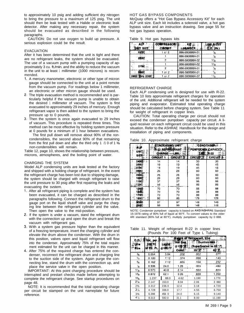
HOT GAS BYPASS COMPONENTSMcQuay offers a “Hot Gas Bypass Accessory Kit” for eachALP unit size. Each kit includes a solenoid valve, a hot gasbypass valve and an instruction drawing. See page 55 forhot gas bypass operation.
Table 9. Hot gas bypass kits
REFRIGERANT CHARGEEach ALP condensing unit is designed for use with R-22.Table 10 lists approximate refrigerant charges for operationof the unit. Additional refrigerant will be needed for the systempiping and evaporator. Estimated total operating chargeshould be calculated before charging system. See Table 11for weight of refrigerant in copper lines.
CAUTION: Total operating charge per circuit should notexceed the condenser pumpdown capacity per circuit. A li-quid receiver on each refrigerant circuit could be used in thissituation. Refer to the ASHRAE Handbook for the design andinstallation of piping and components.
Table 10. Approximate refrigerant charge
NOTE: Condenser pumpdown capacity is based on ANWASHAAE Standard15-1978 rating of 90% full of liquid at 90°F. To convert values to the olderARI standard (80% full at 80°F). multiply pumpdown capacity by 0 888.
Table 11. Weight of refrigerant R-22 in copper lines(Pounds Per 100 Feet of Type L Tubing)
is/8 1 1.237 1 88.0 1 4.62 1 1.190 1.770
2’h 2.147 153.0 8.04 2.06 3 060
2% 3.312 236.0 12.4 3.18 4.720
31/a 4.728 336.0 17.7 4.55 6.750
3% 6.398 456 0 24.0 6.15 9.140
4’ia 1 8.313 1 592.0 1 31.1 1 8.00 1 11.190
IM 269 I Page 9


FIELD WIRING
Wiring must comply with all applicable codes and ordinances.Warranty is voided if wiring is not in accordance with specifi-
cations. An open fuse indicates a short, ground or overload.Before replacing a fuse or restarting a compressor or fanmotor, the trouble must be found and corrected.
Copper wire is required for all power lead terminations atthe unit while either aluminum or copper can be used for allother wiring.
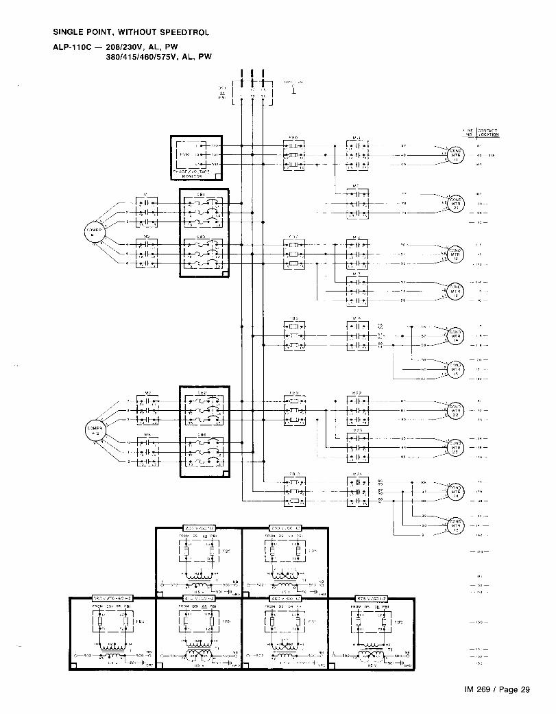
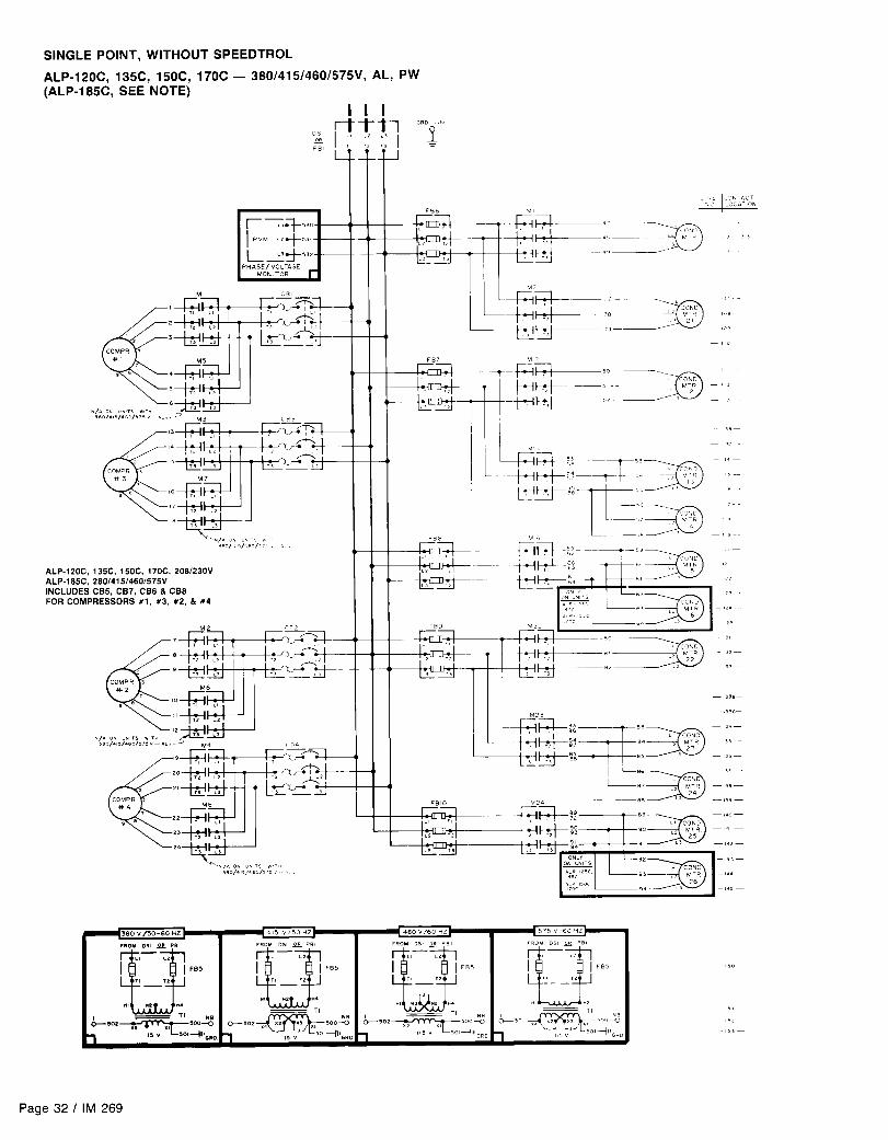
ALP units may be ordered with internal power wiring foreither single or multiple point power connection. If single pointpower connection is ordered, a single large power terminalblock or non-fused disconnect switch is provided and wiringwithin the unit is sized in accordance with the National Elec-trical Code. A single field supplied disconnect is required.An optional factory mounted transformer may be provided.
If multiple point wiring is ordered, three power connections,
one per compressor circuit plus one for condenser fans, arerequired and wiring with the unit is sized in accordance withthe National Electrical Code. Separate field supplied discon-nects are required for each of the three circuits. A singlepower block is provided for all of the condenser fans and theoptional 115V control transformer.
CAUTION: Internal power wiring to the compressors forthe single point versus the the multiple point option are dif-ferent. It is imperative that the proper field wiring be in-stalled according to the way the unit is built.
Figures 10, 11 and 12 show typical field wiring that is re-quired for unit installation. Items that require field wiring areliquid line solenoids (SV1 and SV2), optional hot gas bypasssolenoid (SV5) and the cooling thermostat as well as the unitpower supply.
Figure 10. Typical field wiring diagram for ALP-045C - 08OC with 4 steps of capacity control
FIELD WIRING TERMINAL
- - - FIELD WIRING
- FACTORY WIRING
- - - OPTIONAL FACTORY WIRING
BK BLACK WIRING (LINE)
W H WHlTE WIRING (NEUTRALI
Page 14 I IM 269


Table 18. Capacity reduction
SVl + Comp. 1 + Comp. 3 (R3 energized)
,‘: SV2 + Comp. 2 + Comp. 4 (R4 energized)
SW +Comp. 1, Ul. U2SV2 + Comp. 2, Ul, U2SVI + Comp. 1 (Ul, U2 de-energized)
t7lac, i SV2 + Comp. 2 (Ul, U2 de-energized)
a?$#!& m SVl + Comp. 1, Ul, U2 + Comp. 3 (R3 energized)SV2 + Comp. 2, Ul, U2 + Comp. 4 (R4 energized)
SVl + Comp. 1 + Comp. 3 (Ul, U2 de-energized)
Stage 3 Stage 5
Stage 4 Stage 6
Stage 1 Stag-e 1
Stage 2 Stage 2
Stage 3 Stage 3
Stage 4_I Stage 4- ..-_I Stage 5-
Stage 5--1 1 SV2 + Comp. 2 + Comp. 4 (Ul, UZ Stage 6 Stage 6de-energized) 1 I I
NOTES:1. Compressor staging for units with suction pressure controlled unloaders and unloaders controlled from a remote source (discharge air, return water, etc.) is the same.2. See page 54 for more information on unloaders controlled from suction pressure.
WATER PIPING FOR CHILLED WATER APPLICATIONS
Due to the variety of piping practices, it is advisable to follow the recommendations of localauthorities. They can supply the installer with the proper building and safety codes requiredfor a safe and proper installation.
FLOW SWITCH FOR CHILLED WATER APPLICATIONS
A WATER FLOW SWITCH MUST BE MOUNTED in eitherthe entering or leaving water line to insure that there will beadequate water flow and cooling load to the evaporator beforethe unit can start. This will safeguard against slugging thecompressors on startup. It also serves to shut down the unitin the event that water flow is interrupted to guard againstevaporator freeze-up.
A flow switch is available from McQuay under orderingnumber 860-175033B-00. It is a “paddle” type switch andadaptable to any pipe size from 1” to 6” nominal. Certain
Table 19. Flow switch minimum flow rates Figure 13.
Page 18 / IM 269
minimum flow rates are required to close the switch and arelisted in Table 18. Installation should be as shown in Figure13.
Electrical connections in the unit control center should bemade at terminals 5 and 6. The normally open contacts ofthe flow switch should be wired between these two terminals.There is also a set of normally closed contacts on the switchthat could be used for an indicator light or an alarm to in-dicate when a “no flow” condition exists.

EVAPORATOR FAN INTERLOCK FOR AIR HANDLER COIL INSTALLATIONS
It is important to interlock the air handler evaporator fan withthe condensing unit control to insure that there will be a cool-
purpose. Remove the jumpers between terminals 111 and11.2 for circuit 1 and 211 and 212 for circuit 2. Use these ter-
ing load on the evaporator before the unit can start to pre- minals for the evaporator fan interlock contacts. Be sure tovent compressor slugging. A pair of terminals for eachrefrigerant circuit is available in the unit control center for this
keep circuits separate by using two contacts on dual circuitmachines.
UNIT LAYOUT & PRINCIPLES OF OPERATION
Figure 14. Major Component LocationsThe figures below illustrate component locations within the unit for each unit size.
COMPRESSOR No. 1 -
COMPRESSOR No. 1
I I L---J
COMPRESSOR No. 2 -/
TOP VIEW OF UNIT
COMPRESSOR No. 2 J \_ COMPRESSOR No. 4
CONTROLCENTER
All electrical controls are enclosed in a weatherproof controlcenter with keylocked, hinged access doors. The controlcenter is composed of two separate compartments, linevoltage and control voltage. All of the line voltage com-ponents, except for the input terminals of the PVM, are
located in the compartment on the right side of the unit. Thecontrol voltage components are located on the left side withthe live terminals located behind a deadfront panel. This pro-tects service personnel from live terminals when accessingthe adjustable and resettable controls.
IM 269 I Page 19


NORMAL SEQUENCE OF OPERATION
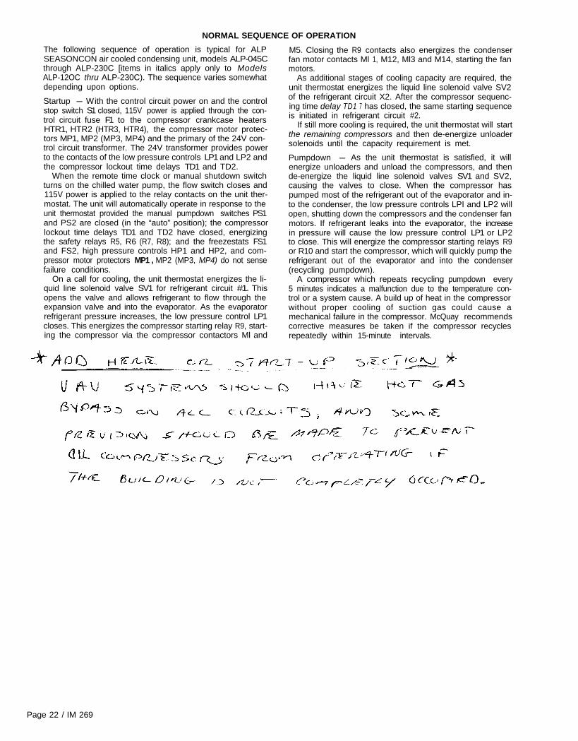
The following sequence of operation is typical for ALPSEASONCON air cooled condensing unit, models ALP-045Cthrough ALP-230C [items in italics apply only to ModelsALP-12OC thru ALP-230C). The sequence varies somewhatdepending upon options.
Startup - With the control circuit power on and the controlstop switch S1 closed, 115V power is applied through the con-trol circuit fuse F1 to the compressor crankcase heatersHTR1, HTR2 (HTR3, HTR4), the compressor motor protec-tors MP1, MP2 (MP3, MP4) and the primary of the 24V con-trol circuit transformer. The 24V transformer provides powerto the contacts of the low pressure controls LP1 and LP2 andthe compressor lockout time delays TD1 and TD2.
When the remote time clock or manual shutdown switchturns on the chilled water pump, the flow switch closes and115V power is applied to the relay contacts on the unit ther-mostat. The unit will automatically operate in response to theunit thermostat provided the manual pumpdown switches PS1and PS2 are closed (in the “auto” position); the compressorlockout time delays TD1 and TD2 have closed, energizingthe safety relays R5, R6 (R7, R8); and the freezestats FS1and FS2, high pressure controls HP1 and HP2, and com-pressor motor protectors MP1 , MP2 (MP3, MP4) do not sensefailure conditions.
On a call for cooling, the unit thermostat energizes the li-quid line solenoid valve SV1 for refrigerant circuit #1. Thisopens the valve and allows refrigerant to flow through theexpansion valve and into the evaporator. As the evaporatorrefrigerant pressure increases, the low pressure control LP1closes. This energizes the compressor starting relay R9, start-ing the compressor via the compressor contactors Ml and
M5. Closing the R9 contacts also energizes the condenserfan motor contacts Ml 1, M12, Ml3 and M14, starting the fanmotors.
As additional stages of cooling capacity are required, theunit thermostat energizes the liquid line solenoid valve SV2of the refrigerant circuit X2. After the compressor sequenc-ing time delay TD1 7 has closed, the same starting sequenceis initiated in refrigerant circuit #2.
If still more cooling is required, the unit thermostat will startthe remaining compressors and then de-energize unloadersolenoids until the capacity requirement is met.
Pumpdown - As the unit thermostat is satisfied, it willenergize unloaders and unload the compressors, and thende-energize the liquid line solenoid valves SV1 and SV2,causing the valves to close. When the compressor haspumped most of the refrigerant out of the evaporator and in-to the condenser, the low pressure controls LPI and LP2 willopen, shutting down the compressors and the condenser fanmotors. If refrigerant leaks into the evaporator, the increasein pressure will cause the low pressure control LP1 or LP2to close. This will energize the compressor starting relays R9or R10 and start the compressor, which will quickly pump therefrigerant out of the evaporator and into the condenser(recycling pumpdown).
A compressor which repeats recycling pumpdown every5 minutes indicates a malfunction due to the temperature con-trol or a system cause. A build up of heat in the compressorwithout proper cooling of suction gas could cause amechanical failure in the compressor. McQuay recommendscorrective measures be taken if the compressor recyclesrepeatedly within 15-minute intervals.
Page 22 / IM 269


STARTUP AND SHUTDOWN
PRE-STARTUP
1.
2.
3.
4.
5.
6.
1.
6.
1. 2.
3.
With all electric disconnects open, check all screw or lugtype electrical connections to be sure they are tight forgood electrical contact. Check all compressor valve con-nections for tightness to avoid refrigerant loss at start-up. Although all factory connections are tight before ship-ment, some loosening may have resulted from shippingvibration.On chilled water installations, check to see that all waterpiping is properly connected.Check the compressor oil level. Prior to startup, the oillevel should cover at least one-third of the oil sightglass.Check the voltage of the unit power supply and see thatit is within the * 10% tolerance that is allowed. Phasevoltage unbalance must be within &20/o.Check the unit power supply wiring for adequate ampaci-ty and a minimum insulation temperature rating of 75C.Verify that all mechanical and electrical inspections havebeen completed per local codes.
10.
CAUTION: Most relays and terminals in the unit control centerare hot with S1 and the control circuit disconnect on. Do notclose S1 until startup.
See that all auxiliary control equipment is operative andthat an adequate cooling load is available for initialstartup.Open the compressor suction and discharge shutoffvalves until backseated. Always replace valve seal caps.Making sure control stop switch S1 is open (off) andpumpdown switches PS1 and PS2 are on “manualpumpdown,” throw the main power and control discon-nect switches to “on.” This will energize crankcaseheaters. Wait a minimum of 12 hours before starting upunit.Open all water flow valves and start the chilled waterpump. Check all piping for leaks and vent the air fromthe evaporator as well as from the system piping to ob-tain clean, non-corrosive water in the evaporator circuit.
INITIAL STARTUP
Double check that the compressor suction and dischargeshutoff valves are backseated. Always replace valve sealcaps.Open the manual liquid line shutoff valve at the outlet ofthe subcooler.Adjust the dial on temperature controller CP1 to thedesired chilled water or leaving air temperature.Start the auxiliary equipment for the installation.Check to see that pumpdown switches PSI and PS2 arein the “manual pumpdown” (open) position. Throw theemergency stop switch S1 to the “on” position. Ifpressures on the low side of the system are above 60 psig,the unit will start and pump down.After the compressor lockout timer TD1 has timed out, start
7.
8.
9.
the system by moving pumpdown switches PS1 and PS2to the “auto pumpdown” position.After running the unit for a short time, check the oil levelin each compressor crankcase, rotation of condenser fans,and check for flashing in the refrigerant sightglass (see“Maintenance”, page 49).Superheat should be adjusted to maintain between 8 and12 degrees F.After system performance has stabilized, it is necesary thatthe “Compressorized Equipment Warranty Form” (FormNo. 415415Y) be completed to obtain full warrantybenefits. This form is shipped with the unit, and after com-pletion should be returned to McQuay’s Service Depart-ment through your sales representative.
TEMPORARY SHUTDOWN
Move pumpdown switches PS1 and PS2 to the “manual pumpdown” position. Afterthe compressors have pumped down, turn off the chilled water pump or evaporatorfan. It is especially important on chilled water installations that the compressors pumpdown before the water flow to the evaporator is interrupted to avoid freeze-up.
CAUTION: With the unit left in this condition, it is capable of recycling pumpdownoperation. To defeat this mode of operation, move control stop switch S1 to the “off”position.
STARTUP AFTER TEMPORARY SHUTDOWN1. Start the chilled water pump.2. With emergency stop switch S1 in the “on” position, move pumpdown switches
PS1 and PS2 to the “auto pumpdown” position.3. Observe the unit operation for a short time to be sure that the compressors do
not cut out on low oil pressure.
EXTENDED SHUTDOWN(For startup after extended shutdown, refer to applicable “Initial Startup” steps.)
Close the manual liquid line shutoff valves.After the compressors have pumped down, turn off thechilled water pump or evaporator fan.Turn off all power to the unit and to the auxiliaryequipment.
4.5.6.
Move the control stop switch S1 to the “off” position.Close the compressor suction and discharge valves.Tag all opened disconnect switches to warn against start-up before opening the compressor suction and dischargevalves.
Page 48 I IM 269

SYSTEM MAINTENANCE
GENERAL
On initial startup and periodically during operation, it will be supports on each side of the unit adjacent to the compressors.necessary to perform certain routine service checks. Among The gauges are factory installed with a manual shutoff valvethese are checking the compressor oil level and taking con- on each gauge line. The valves should be closed at all timesdensing, suction and oil pressure readings. During operation, except when gauge readings are being taken. On unitsthe oil level should be visible in the oil sightglass with the ordered without gauges, Shrader fittings should be installedcompressor running. On units ordered with gauges, conden- in the plugged ports provided on the suction and dischargesing, suction and oil pressures can be read from the vertical King valves on each compressor circuit.
FAN SHAFT BEARINGS
The fan shaft bearings are of the permanently lubricated type. No lubrication is required.
ELECTRICAL TERMINALS
CAUTION: Electric shock hazard. Turn off all power before continuing with the follow.ing service.
All power electrical terminals should be retightened every six months, as they tendto loosen in service due to normal heating and cooling of the wire.
COMPRESSOR OIL LEVEL
Because of the large refrigerant charge required in an air cool-ed condensing unit, it is usually necessary to put additionaloil into the system. The oil level should be watched carefullyupon initial startup and for sometime thereafter.
At the present time, Suniso No. 3GS, Calumet R015, andTexaco WF32 oils are approved by Copeland for use in thesecompressors. The oil level should be maintained at about one-third of the sightglass on the compressor body.
Oil may be added to the Copeland compressor through theoil fill hole in the crankcase. To add oil, isolate the crankcaseand pour or pump in the necessary oil. If the system containsno refrigerant, no special precautions are necessary other
than keeping the oil clean and dry.If the system contains a refrigerant charge, close the suc-
tion valve and reduce crankcase pressure to 1 to 2 psig. Stopthe compressor and close the discharge valve.
Add the required amount of oil. During the period the com-pressor is exposed to the atmosphere, the refrigerant willgenerate a vapor pressure, retarding the entrance of con-taminants. Before resealing the compressor, purge thecrankcase by opening the suction valve slightly for 1 or 2seconds. Close the oil port, open the compressor valves andrestore the system to operation.
CONDENSERS
Condensers are air cooled and constructed with s/8” O.D. in-ternally finned copper tubes bonded in a staggered patterninto slit aluminum fins. No maintenance is ordinarily requiredexcept the occasional removal of dirt and debris from the out-side surface of the fins. McQuay recommends the use offoaming coil cleaners available at air conditioning supply
outlets. Use caution when applying such cleaners as they maycontain potentially harmful chemicals. Care should be takennot to damage the fins during cleaning. Periodic use of thepurge valve on the condenser will prevent the buildup ofnon-condensables.
REFRIGERANT SIGHTGLASS
The refrigerant sightglasses should be observed period-ically. (A monthly observation should be adequate.) A clear
or a restriction elsewhere in the system. On sightglasses
glass of liquid indicats that there is adequate refrigerantordered from McQuay as part of the “Liquid Line Accessory
charge in the system to insure proper feed through the ex-Kits” listed on page 8, an element inside the sightglass in-
pansion valve. Bubbling refrigerant in the sightglass indicatesdicates what moisture condition corresponds to a given ele-
that the system is short of refrigerant charge. Refrigerant gasment color. If the sightglass does not indicate a dry condi-tion after about 12 hours of operation, the unit should be
flashing in the sightglass could also indicate an excessivepressure drop in the line, possibly due to a clogged filter-drier
pumped down and the filter-driers changed.
IM 269 / Page 49

SERVICENOTE: Service on this equipment is to be performed by qualified refrigeration service per-sonnel. Causes for repeated tripping of safety controls must be investigated and corrected.CAUTION: Disconnect all power before doing any service inside the unit.
FILTER-DRIERS
To change the filter-drier, pump the unit down by movingpumpdown switches PS1 and PS2 to the “manual pump-down” position.
trol. Close the manual liquid line shutoff valve(s). Turn powerto the unit back on and restart the unit by moving the controlswitch S1 to the “on” position. The unit will start pumpingdown past the low pressure setting. When the evaporatorpressure reaches O-5 psig, move control switch S1 to the“off” position.
Move the control switch S1 to the “off” position. Turn off allpower to the unit and install jumpers across the terminalsshown in the table. This will jump out the low pressure con-
Frontseat the suction line King valve(s). Remove andreplace the filter-drier(s). Evacuate the lines through the li-quid line manual shutoff valve(s) to remove non-condensablesthat may have entered during filter replacement. A leak checkis recommended before returning the unit to operation.
LIQUID LINE SOLENOID VALVE
The liquid line solenoid valves, which are responsible forautomatic pumpdown during normal unit operation, do notnormally require any maintenance. They may, however, re-quire replacement of the solenoid coil or of the entire valveassembly.
The solenoid coil may be removed from the valve bodywithout opening the refrigerant piping by moving pumpdownswitches PS1 and PS2 to the “manual pumpdown” position.
THERMOSTATIC EXPANSION VALVE
The expansion valve is responsible for allowing the properamount of refrigerant to enter the evaporator regardless ofcooling load. It does this by maintaining a constant superheat.(Superheat is the difference between refrigerant temperatureas it leaves the evaporator and the saturation temperaturecorresponding to the evaporator pressure.) Typically,superheat should run in the range of 10” F to 15” F. On valvespurchased through McQuay, the superheat setting can beadjusted by removing the cap at the bottom of the valve toexpose the adjustment screw. Turn the screw clockwise(when viewed from the adjustment screw end) to increase
the superheat setting and counterclockwisesuperheat. Allow time for system rebalancesuperheat adjustment.
The expansion valve, like the solenoid valve, should notnormally require replacement, but if it does, the unit mustbe pumped down by following the steps involved when chang-ing a filter-drier.
If the problem can be traced to the power element only,it can be unscrewed from the valve body without removingthe valve, but only after pumping the unit down.
INLET
The coil can then be removed from the valve body by simplyremoving a nut or snap-ring located at the top of the coil. Thecoil can then be slipped off its mounting stud for replacement.Be sure to replace the coil on its mounting stud before retur-ning pumpdown switches PS1 and PS2 to the “auto pump-down” position.
To replace the entire solenoid valve follow the steps in-volved when changing a filter-drier.
to reduceafter each
POWER ELEMENT(CONTAINS DIAPHRAGM)
OUTLET
ADJUSTMENT SCREW
/- CAP
Page 50 I IM 269

IN-WARRANTY RETURN MATERIAL PROCEDURE
COMPRESSOR
Copeland Refrigeration Corporation has stocking wholesalerswho maintain a stock of replacement compressors and ser-vice parts to serve refrigeration contractors and servicemen.
When a compressor fails in warranty, contact your localsales representative, or McQuay Warranty Claims Deparmentat the address on the cover of this bulletin. You will beauthorized to exchange the defective compressor at aCopeland wholesaler, or an advance replacement can be ob-tained. A credit is issued you by the wholesaler for the re-turned compressor after Copeland factory inspection of theinoperative compressor. If that compressor is out ofCopeland’s warranty, a salvage credit only is allowed. Pro-
vide McQuay with full details; i.e., McQuay unit model andunit serial numbers. Include the invoice and the salvage valuecredit memo copies and we will reimburse the difference. Inthis transaction, be certain that the compressor is definitelydefective. If a compressor is received from the field that testssatisfactorily, a service charge plus a transportation chargewill be charged against its original credit value.
On all out-of-warranty compressor failures, Copeland of-fers the same field facilities for service and/or replacementas described above. The credit issued by Copeland on thereturned compressor will be determined by the repair chargeestablished for that particular unit.
COMPONENTS OTHER THAN COMPRESSORS
Material may not be returned except by permission ofauthorized factory service personnel of McQuay Air Condi-tioning at Minneapolis, Minnesota. A “return goods” tag willbe sent to be included with the returned material. Enter the
The return of the part does not constitute an order forreplacement. Therefore, a purchase order must be enteredthrough your nearest McQuay representative. The order
information as called for on the tag in order to expedite han-dling at our factories and prompt issuance of credits.
should include part name, part number, model number andserial number of the unit involved.
Following our personal inspection of the returned part, and
All parts shall be returned to the pre-designated McQuayfactory transportation charges prepaid.
if it is determined that the failure is due to faulty material orworkmanship, and in warranty, credit will be issued oncustomer’s purchase order.
APPENDIXSTANDARD CONTROLS
NOTE: PERFORM AN OPERATIONAL CHECK ON ALL UNIT SAFETY CONTROLS ONCE PER YEAR.
OIL PRESSURE SAFETY CONTROL
The oil pressure safety control is a manually resettable devicewhich senses the differential between oil pressure at thedischarge of the compressor oil pump and suction pressureinside the compressor crankcase. When the oil pressurereaches approximately 15 psi above the crankcase suctionpressure, the pressure actuated contact of the control opensfrom its normally closed position. If this pressure differentialcannot be developed, the contact will remain closed andenergize a heater element within the control. The heater ele-ment warms a normally closed bimetallic contact and causesthe contact to open, de-energizing a safety relay and break-ing power to the compressor.
minutes for the heater element and bimetallic contacts to cooland reset the control again.
It takes about 120 seconds to warm the heater elementenough to open the bimetallic contact, thus allowing time forthe pressure differential to develop.
If during operation, the differential drops below 10 psi, theheater element will be energized and the compressor willstop. The control can be reset by pushing the reset buttonon the control. If the compressor does not restart, allow a few
To check the control, pump down and shut off all powerto the unit. Open the circuit breakers or the fused discon-nect for that compressor and install a voltmeter between ter-minals L and M of the oil pressure control. Turn on powerto the unit control circuit (separate disconnect or main unitdisconnect depending on the type of installation). Check tosee that the control stop switch S1 is in the “on” position.The control circuit should now be energized, but with theabsence of compressor power, no oil pressure differential candevelop and thus the pressure actuated contacts of the con-trol will energize the heater element and open the bimetalliccontacts of the control within 120 seconds. When this hap-pens, the safety relay is de-energized, the voltmeter readingwill rise to 24V, and the compressor contactor should open.Repeated operations of the control will cause a slight heatbuildup in the bimetallic contacts resulting in a slightly longertime for reset with each successive operation.
Pressure ActuatorContact
Heater ElementNeutral
Line
Note 2
L M*IIX
Bimetall ic Contacts
Neutral
Safety Relay
IM 269 / Page 51

HIGH PRESSURE CONTROL
The high pressure control is a single pole pressure activated trol on a high pressure gauge.switch that closes on a pressure rise. When the switch closes, The control is attached to a Shrader fitting and is locatedR1 is energized which in turn de-energizes the control cir- on a cylinder head near the discharge King valve. CAUTION:cuit, shutting down the compressor circuit. R1 also locks itself Although there is an additional pressure relief device in thein a manually resettable holding circuit through RS1. The system set at 450 psig, it is highly recommended that theswitch is factory set to close at 400 psig and open at 300 psig. “control stop” switch S1 be close at hand in case the high
To check the control, either block off condenser surface pressure control should malfunction.or start the unit with condenser fan motor fuses in only one After testing the high pressure control, check the pressurefan fuse block (FB6) and observe the cutout point of the con- relief device (on the condenser header) for leaks.
LOW PRESSURE CONTROL
The low pressure control is a single pole pressure switch that lowest evaporator pressure reached before cutout is thecloses on a pressure rise. It senses evaporator pressure and cutout setting of the control. Wait for the compressor lockoutis factory set to close at 60 psig and automatically open at time delays TD1 and TD2 to time out. By moving the pump-25 psig. The control has an adjustable range of 20 inches down switch(es) PSI and PS2 to the “auto pumpdown” posi-of Hg. to 100 psig and an adjustable differential of 6 to 40 tion, evaporator pressure will rise. The highest evaporatorpsig. To check the control (unit must be running), move the pressure reached before compressor restart is the cut-in set-pumpdown switch(es) PS1 and PS2 to the “manual pump- ting of the control.down” position. As the compressor pumps down, condenser The control is attached to a Shrader fitting and is locatedpressure will rise and evaporator pressure will drop. The below the suction King valve body.
FANTROL HEAD PRESSURE CONTROL
FANTROL is a method of head pressure control whichautomatically cycles the condenser fans in response to con-denser pressure and ambient air temperature. This maintainshead pressure and allows the unit to run at low ambient airtemperatures.
All ALP units have dual independent circuits with the fansfor circuit 1 and circuit 2 being controlled independently bythe condensing pressure and ambient air of each circuit. Fans
Table 23. Factory FANTROL Settings
11 and 21 start with each compressor and fans 12 and 22cycle on and off in response to condenser pressure. The cut-out and cut-in pressures are given in Table 23. Fans 13 and14 (circuit 1) and fans 23 and 24 (circuit 2) are con-trolled by ambient temperature and are factory set at thevalues given in Table 23. Note that the number of fans oneach unit varies. FANTROL sensor locations are shown inFigures 20 thru 23.
NOTES:(1) With SPEEDTROL, all units minimum ambient operating temperature drops to 0°F.(2) Minimum head pressure on partly loaded compressor is 110 psig; on full load it is 170 psig.
Figure 20. Figure 21. SPEEDTROL Controls
Page 52 / IM 269

Figure 22.
FANTROL Sensors.PC22 & PC12
Figure 23.
COMPRESSOR LOCKOUT
Compressor lockout consists of an adjustable 0 to 6 minutetime delay. It is wired in series with the R 5 relay that energizesthe R9 relay starting the compressor. Its purpose is to pre-vent rapid compressor cycling when cooling demands are er-ratic. The circuit illustrated is for the compressor circuit #1control circuit. The control circuit for compressor circuit #2is wired the same way. Five minutes is recommended for thecompressor lockout time delay.
When the unit thermostat no longer calls for cooling andthe compressor contactor have opened, the lockout timedelay breaks open the circuit, preventing compressor restart.
The circuit remains open for a period of 5 minutes so that,if the unit thermostat should call for cooling before the delayperiod has expired, the compressor will not restart. After 5minutes the time delay will close its contacts to complete thecircuit to R5 energizing R9 and starting the compressor.When R9 is energized another set of contacts will shuntaround TD1, allowing TD1 to reset open for timing out thenext compressor cycle.
To check the control, the compressor must be running in-itially. Move the pumpdown switch PS1 or PS2 to the “manualpumpdown” position. Immediately after the compressor hasstopped running, move the pumpdown switch back to the“auto pumpdown” position. The compressor should notrestart for 5 minutes.
Line Neutral
,net~~ - I@ Neutral
‘---II-----JLine -. 7; m Neutral
COMPRESSOR MOTOR PROTECTOR
The solid-state compressor motor protector module incor-porates a two-minute “time off” relay utilizing the bleed downcapacitor principle. Any time the protection system opens orpower to the module is interrupted, the two-minute “time off”delay is triggered, and the module will not reset for twominutes. Once the two-minute period is passed, the motorprotector contacts 1 and 2 reset, provided the protectionsystem is satisfied and power is applied to the module.
NOTE: If the power circuit is broken once the two-minuteperiod is passed the pilot circuit will reset without delay whenpower is reapplied.
l------24V Ltne Neutral
I MPl I115v Line
- - -t-. ’ Neutral
12___4_ 1
IM 269 / Page 53
APPENDIXOPTIONAL CONTROLS
SPEEDTROL HEAD PRESSURE CONTROL (OPTIONAL)
The SPEEDTROL system of head pressure control operates partments. Units with 460 volt power have a transformerin conjunction with FANTROL by modulating the motor speed mounted inside the condenser fan 21 fan compartment to stepon fans 11 and 21 in response to condensing temperature. the voltage down to 230 volts for the SPEEDTROL motors.By reducing the speed of the last fan as the condensing The SPEEDTROL control starts to modulate the motorpressure falls, the unit can operate at lower ambient speed at approximately 105°F and maintains a minimum con-temperatures. densing pressure of 170 to 180 psig.
The SPEEDTROL fan motor is a single phase, 2081240 volt, The SPEEDTROL sensors are clipped to a return bend onthermally protected motor specially designed for variable the bottom row of the condenser coil. SPEEDTROL controlsspeed application. The solid-state speed controls SC1 1 and and SPEEDTROL transformer are shown in Figures 21 andSC21 are mounted inside condenser fan 11 and 21 fan com- 23.
COMPRESSOR UNLOADERS (OPTIONAL)
UNLOADERS CONTROLLED FROM SUCTION PRESSURE:With a decrease in load, the suction pressure drops, pressure solenoid U1 which increases the compressor capacity.control PC8 closes, energizing unloader solenoid U1. Thiscloses the suction port to one cylinder bank and reduces the
PC8, cut-in: 64 psig; cut-out: 72 psig
compressor capacity. Compressor circuit 2 operates the samePC9, cut-in: 64 psig; cut-out: 72 psig
way. The cut-in and cut-out pressures can be adjusted to meet fieldWith an increase in the load, the suction pressure in- combinations. If the unloader cycles excessively, the differen-
creases, pressure control PC8 opens, de-energizing unloader tial between cut-in and cut-out should be increased.
LOW AMBIENT START (OPTIONAL)
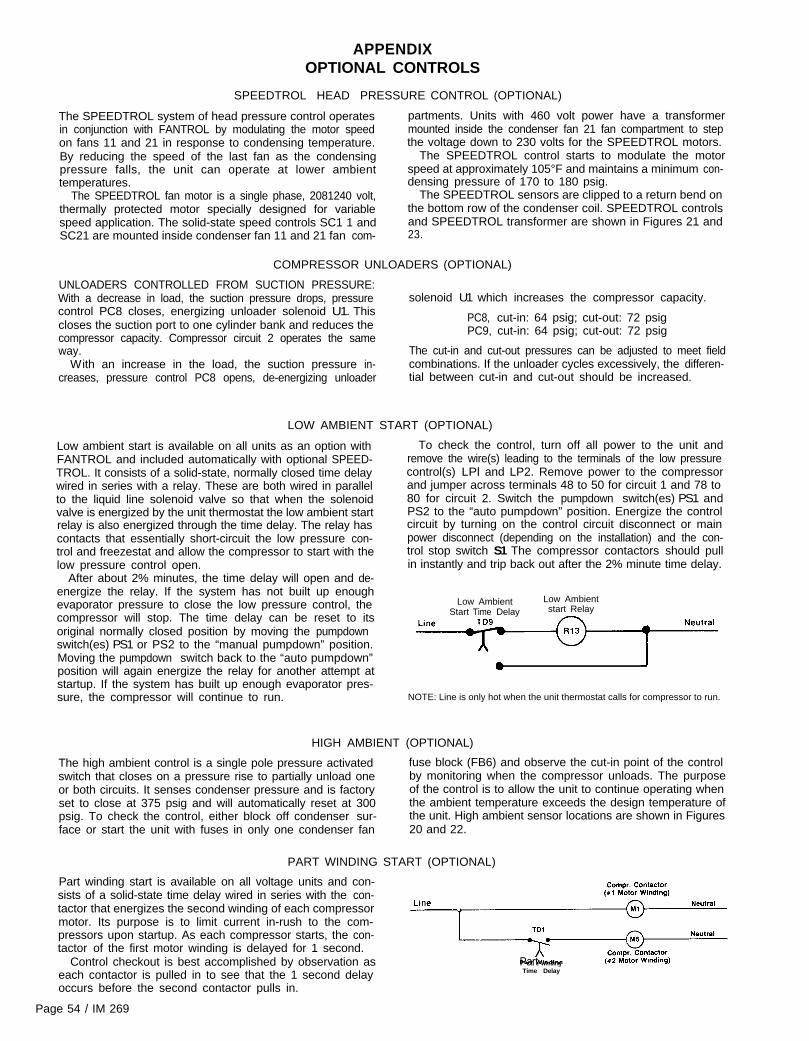
Low ambient start is available on all units as an option withFANTROL and included automatically with optional SPEED-TROL. It consists of a solid-state, normally closed time delaywired in series with a relay. These are both wired in parallelto the liquid line solenoid valve so that when the solenoidvalve is energized by the unit thermostat the low ambient startrelay is also energized through the time delay. The relay hascontacts that essentially short-circuit the low pressure con-trol and freezestat and allow the compressor to start with thelow pressure control open.
After about 2% minutes, the time delay will open and de-
To check the control, turn off all power to the unit andremove the wire(s) leading to the terminals of the low pressurecontrol(s) LPl and LP2. Remove power to the compressorand jumper across terminals 48 to 50 for circuit 1 and 78 to80 for circuit 2. Switch the pumpdown switch(es) PS1 andPS2 to the “auto pumpdown” position. Energize the controlcircuit by turning on the control circuit disconnect or mainpower disconnect (depending on the installation) and the con-trol stop switch S1 The compressor contactors should pullin instantly and trip back out after the 2% minute time delay.
energize the relay. If the system has not built up enoughevaporator pressure to close the low pressure control, thecompressor will stop. The time delay can be reset to itsoriginal normally closed position by moving the pumpdownswitch(es) PS1 or PS2 to the “manual pumpdown” position.Moving the pumpdown switch back to the “auto pumpdown”position will again energize the relay for another attempt atstartup. If the system has built up enough evaporator pres-sure, the compressor will continue to run.
Low Ambient Low AmbientStart Time Delay start Relay
0
NOTE: Line is only hot when the unit thermostat calls for compressor to run.
HIGH AMBIENT (OPTIONAL)
The high ambient control is a single pole pressure activatedswitch that closes on a pressure rise to partially unload oneor both circuits. It senses condenser pressure and is factoryset to close at 375 psig and will automatically reset at 300psig. To check the control, either block off condenser sur-face or start the unit with fuses in only one condenser fan
fuse block (FB6) and observe the cut-in point of the controlby monitoring when the compressor unloads. The purposeof the control is to allow the unit to continue operating whenthe ambient temperature exceeds the design temperature ofthe unit. High ambient sensor locations are shown in Figures20 and 22.
PART WINDING START (OPTIONAL)
Part winding start is available on all voltage units and con-sists of a solid-state time delay wired in series with the con-tactor that energizes the second winding of each compressormotor. Its purpose is to limit current in-rush to the com-pressors upon startup. As each compressor starts, the con-tactor of the first motor winding is delayed for 1 second.
Control checkout is best accomplished by observation aseach contactor is pulled in to see that the 1 second delayoccurs before the second contactor pulls in.
Page 54 / IM 269
-
Line I?--Part WindingTime Delay

PHASE/VOLTAGE MONITOR (OPTIONAL)
tection against three-phase electrical motor loss due to powerfailure conditions, phase loss, and phase reversal. Wheneverany of these conditions occur, an output relay is deactivated,disconnecting power to the thermostatic control circuit,automatically pumping down the unit.
The phase/voltage monitor is a device which provides pro- put relav does not close. oerform the followina tests.i.
2.
Check the voltages between Ll-L2, L1-L3-and L2-L3.These voltages should be approximately equal and within+ 10% of the rated three-phase line-to-line voltage.If these voltages are extremely low or widely unbalancedcheck the power system to determine the cause of theproblem.The output relay remains deactivated until power line con-
ditions return to an acceptable level. Trip and reset delayshave been provided to prevent nuisance tripping due to rapidpower fluctuations.
3.
When three-phase power has been applied, the output relayshould close and the “run light” should come on. If the out-
If the voltages are good, turn off the power and interchangeany two of the supply power leads at the disconnect.
This may be necessary as the phase/voltage monitoris sensitive to phase reversal. Turn on the power. The out-put relay should now close after the appropriate delay.
HOT GAS BYPASS (OPTIONAL)
Hot gas bypass is a system for maintaining evaporatorpressure at or above a minimum value. The purpose for do-ing this is to keep the velocity of the refrigerant as it passesthrough the evaporator high enough for proper oil return tothe compressor when cooling load conditions are light. It alsomaintains continuous operation of the chiller at light load con-ditions. Hot gas bypass kits are described on page 9.
The solenoid valve should be wired to open whenever theunit thermostat calls for the first stage of cooling (see Figures10 thru 12). The pressure regulating valve that McQuay of-fers is factory set to begin opening at 58 psig (32F for R-22)when the air charged bulb is in an 80F ambient temperature.The bulb can be mounted anywhere as long as it senses afairly constant temperature at various load conditions. Thecompressor suction line is one such mounting location. It isgenerally in the 50F to 60F range. The chart below indicatesthat when the bulb is sensing 50F to 60F temperatures, thevalve will begin opening at 54 to 56 psig. This setting canbe changed as indicated above, by changing the pressureof the air charge in the adjustable bulb. To raise the pressuresetting, remove the cap on the bulb and turn the adjustment
Hot Gas Bypass Piping Diagram
Hot Gas BypassSolenoid Valve
4Suction Line
External EqualizerConnection to SuctionSide of Evaporator
To Evaporator InletAfter Expansion Valve
Bypass Valve(On OX coils withdistributors, useSporlan auxiliarysideport connectoror equivalent)
screw clockwise. To lower the setting, turn the screwcounterclockwise. Do not force the adjustment beyond therange it is designed for, as this will damage the adjustmentassembly.
The regulating valve opening point can be determined byslowly reducing the system load (or increasing the requiredchilled water temperature setting indicated on the unit ther-mostat), while observing the suction pressure. When thebypass valve starts to open, the refrigerant line on theevaporator side of the valve will begin to feel warm to thetouch.
CAUTION: The hot gas line may become hot enough to causeinjury in a very short time, so care should be taken duringvalve checkout.
On installations where the condensing unit is remote fromthe evaporator, it is recommended that the hot gas bypassvalve be mounted near the condensing uni! to minimize theamount of refrigerant that will condense in the hot gas lineduring periods when hot gas bypass is not required.
Hot Gas Bypass Adjustment Range
REMOTE BULB ADJUSTMENT RANGE
6 80
zP$
7 0 4z
2 Jgz 6 0 Z$
?aE 2
P 50z f
2
O2
4 0
ti> 301 I I I I I I
3 0 4 0 50 6 0 7 0 SO 9 0 100 110
TEMP. (OF) AT BULB LOCATION
IM 269 / Page 55
TROUBLESHOOTING CHART
COMPRESSOR WILLNOT RUN
COMPRESSOR NOISYOR VIBRATING
HIGH DISCHARGEPRESSURE
LOW DISCHARGEPRESSURE
HIGH SUCTIONPRESSURE
LOW SUCTIONPRESSURE
COMPRESSOR WILLWILL NOT UNLOADOR LOAD
COMPRESSORLOADING/UNLOADINGINTERVALSTOO SHORT
LOSS OF OILPRESSURE ORNUISANCE OILPRESSURECONTROLTRIPS
COMPRESSORLOSES OIL
6.7.6.9.
Main switch open.Fuse blown. Circuit breakers open.
Thermal overloads tripped.
Defectve contactor or coil.System shut down by safety devices
No cooling required.Liquid line solenoid will not open.Motor electrical trouble.Loose wiring
1. Flooding of refrigerant into crankcase2. Improper piping support on suction or liquid line3. Worn compressor.
1. Noncondensables in system.2. System overcharged with refrigerant.3. Discharge shutoff valve partially closed.4. Fan not running.5. Dirty condenser c o i l6. FANTROL out of adjustment.
1. Check setting of expansion valve.2. Relocate, add or remove hangers3. Replace.
1. Purge the noncondensables.2. Remove excess.3. Open valve.4. Check electrical circuit.5. Clean coil.6. Adjust FANTROL settinqs.
1. Faulty condenser temperature regulation.2. Suction shutoff valve partially closed3. Insufficient refrigerant in system.4. Low suction pressure.5. Compressor operating unloaded
1. Check condenser control operation.2. Open valve.3. Check for leaks. Rapair and add charge.4. See Corrective Steps for low suction pressure5. See Corrective Steps for failure of compressor
below.
1. Excessive load. 1. Reduce load or add additional equipment.2. Expansion valve overfeeding. 2. Check remote bulb. Regulate superheat.3. Compressor unloaders open 3. See Corrective Steps below for failure of comp
1. Lack of refrigerant2. Evaporator dirty.3. Clogged liquid line filter-drier4. Clogged suction line or compressor suction gas s5. Expansion valve malfunctioning.6. Condensing temperature too low.7. Compressor will not load.
8. Insufficient air or water flow. 8. Adjust airflow or water gpm.
1. Defective capacity control. 1 Replace.2. Unloader mechanism defective. 2. Replace.3. Faulty thermostat stage or broken capillary tube. 3. Replace.4. Staaes not set for application. 4. Reset thermostat setting to fit application.
1. Erratic water thermostat. 1 Replace.2. Insufficient water flow 2 Adjust gpm
1. Clogged suction oil strainer2. Excessive liquid in crankcase.
3. Oil pressure gauge defective
6. Oil pump reversing gear stuck in wrong position.
4. Low oil pressure safety switch defective.5. Worn oil pump.
7. Worn bearings.8. Low oil level.
6 Reverse direction of compressor rotation.7. Replace compressor.
3 Repair or replace. Keep valve closed except w
6. Add o i l .
readings.4 Replace.5. Replace
9. Loose fitting on oil lines.10. Pump housing gasket leaks.11. Flooding of refrigerant into crankcase.12. Iced up evaporator coil.13. Insufficient air or water flow.
9. Check and tighten system.10. Replace gasket.11. Adjust thermal expansion valve.12 Clean coil.13. Adjust air flow or water qpm.
1. Lack of refrigerant. 1. Check for leaks and repair Add refrigerant.2. Excessive compression ring blow-by 2. Replace compressor.3. Suction superheat too high 3. Adjust superheat.4. Crankcase heater burned out. 4. Replace crankcase heater.5. Insufficient oil in system. 5. Add o i l until sightglass IS l/3 full.6. Suction risers too large 6. Check line sizing at design conditions and cha
7. Insufficient traps in suction risers.
6.7.8.9.
Close switch.Check electrical circuits and motor winding forgrounds Investigate for possible overloading.fuse or reset breakers after fault is corrected.loose or corroded connections.Overloads are auto reset. Check unit closely wcomes back on line.Repair or replace.Determine type and cause of shutdown and ccbefore resetting safety switch.None. Wait until unit calls for coolingRepair or replace coil.Check motor for opens, short circuit, or burnoCheck all wire junctions. Tighten all terminal s
shorts orReplaceCheck for
hen unit
rrect it
utcrews.
below.to load
load.
1. Check for leaks. Repair and add charge2. Clean chemically.3. Replace.4 Clean strainers.5. Check and reset for proper superheat.6. Check means for regulating condensing tempe7. See Corrective Steps below for failure of comp
unload.
ressor to
rature.ressor to
1. Clean.2. Check crankcase heater. Reset expansion va l
higher superheat. Check liquid line solenoid vioperation.
ve foralve
hen taking
incorrect.7. Install suction P-traps at each 20 foot vertical
nge if
rise.
Continued on Next Page
Page 58 / IM 269

COMPRESSORTHERMALPROTECTOR SWITCHOPEN
TROUBLESHOOTING CHART (Continued)
1.2.3.4.5.
6.7
Low voltage during high load conditionsDefective or grounded wiring in motorLoose power wiringHigh condensing temperature.Power line fault causing unbalanced voltage.
H igh ambient temperature around the overload relayFailure of second starter to pull in on part winding startsystems
1. Operating beyond design conditions2. Discharge valve partially shut.3 Blown valve plate gasket
12.34.5
6.7.
Check supply voltage for excessive line drip.Replace compressor motor.Check all connections and tighten.See Corrective Steps for high discharge pressure.Check supply voltage. Notify power company. Do notstart until fault is corrected.Provide ventilation to reduce heat.Repair or replace starter or time delay mechanism
1 Add facilities so conditions are within allowable limits.2 Open valve.3 Replace gasket
IM 269 / Page 59