Embed Size (px)
Citation preview

Limitorque MX Electronic ActuatorFCD LMENIM2306-06 - 10/13
USER INSTRUCTIONS
InstallationOperation
Maintenance
Experience In Motion
Limitorque MX Electronic Actuator FCD LMENIM2306-06 – 10/13
2
Contents1 Important Notes 72 Quick Start 9
2.1 Calibrate – Position Limits 92.1.1 Entering the Setup Mode 102.1.2 Electrical Operation Feature 102.1.3 Handwheel Operation Feature 11
2.2 DDC/Modbus Option 132.3 Check the Settings 13
3 Installation and Operation 143.1 Preparing the Stem Nut 14
3.1.1 Type “B” Bases: Torque-only Applications 143.1.2 Type “A” Bases: Thrust-only Applications 163.1.3 Type “BL” Drive: Splined Drive Application 20
3.2 Mechanical Installation Onto Valve or Gearbox 203.2.1 Mounting (Type “B” Bases): Torque-only 213.2.2 Removal (Type “B” Bases): Torque-only 213.2.3 Mounting (Type “A” Bases): Thrust-only 213.2.4 Removal (Type “A” Bases): Thrust-only 21
3.3 Electrical Connections 223.3.1 Removing Terminal Cover 223.3.2 Terminal Compartment Documents 223.3.3 Sealing Cable/Conduit Entries 223.3.4 Recommended Terminal Connections 223.3.5 Termination of Cables 243.3.6 Cable Connections 243.3.7 Network Installations 243.3.8 Foundation Fieldbus Installation 283.3.9 Network Wiring – Profibus DP/PA Installation 293.3.10 Network Wiring – DeviceNet 293.3.11 HART Installation 303.3.12 Replacing Terminal Cover 303.3.13 External Earth/Ground Connections 30
3.4 Terminal Block Shield Installation 303.5 Commissioning the Actuator 30
3.5.1 Default Configuration Set 313.5.2 View the Existing Settings 323.5.3 Entering the Setup Mode 323.5.4 Setting Position Limits 33
3.6 Operating the MX Actuator 363.6.1 Manual Operation 363.6.2 Electrical Operation 363.6.3 Local Control 363.6.4 Remote Control 373.6.5 Local Indication 37
4 Customizing the Actuator 384.1 Changing the Existing Settings 384.2 Password Entry 414.3 New Password 414.4 Valve Setup 42

3
Limitorque MX Electronic Actuator FCD LMENIM2306-06 – 10/13
flowserve.com
4.4.1 Close Direction 424.4.2 Close Seating 424.4.3 Open Seating 42
4.5 Torque Switch Timer 434.5.1 Status 434.5.2 Torque Timer 43
4.6 Torque Setup 444.6.1 Close Torque Valve or Open Torque Valve 44
4.7 Position Setup 454.7.1 Set Position Limits for Electrical Operation 454.7.2 Set Position Limits for Manual Operation 45
4.8 Modutronic Option 474.8.1 Status 474.8.2 Proportional Band 474.8.3 Fail Position 474.8.4 Deadband 474.8.5 Polarity (20 mA) 474.8.6 Delay After Stop 484.8.7 4-20 mA Signal Range 484.8.8 Set High Reference 484.8.9 Set Low Reference 484.8.10 Modutronic LCD Display 49
4.9 DDC/Modbus Option 494.9.1 Status 494.9.2 Network Address 504.9.3 Protocol 504.9.4 Analog Scale 504.9.5 ESD Action 504.9.6 Proportional Band 514.9.7 Deadband 514.9.8 Offset 514.9.9 Move To 514.9.10 Comm Loss Delay 514.9.11 Comm Loss Action 51
4.10 FF Option 514.10.1 Status 524.10.2 Terminate Bus 524.10.3 Analog Scale 524.10.4 ESD Action 524.10.5 OPEN/CLOSE Mode 524.10.6 Proportional Band 524.10.7 Deadband 524.10.8 Comm Loss Delay 534.10.9 Comm Loss Action 53
4.11 PB Option 534.11.1 Status 544.11.2 PB DP Operation 544.11.3 Comm Loss Delay 554.11.4 Comm Loss Action 55
4.12 DN Option 564.12.1 Status 564.12.2 Baud Rate 56

Limitorque MX Electronic Actuator FCD LMENIM2306-06 – 10/13
4
4.12.3 Network Address 564.12.4 Analog Scale 564.12.5 ESD Action 564.12.6 Proportional Band 574.12.7 Deadband 574.12.8 Comm Loss Delay 574.12.9 Comm Loss Action 57
4.13 HART Option 584.13.1 Status 584.13.2 Multi-drop 584.13.3 Input Action 594.13.4 Fail Position 594.13.5 Polling Address 594.13.6 Save Settings 594.13.7 Change Prop/Deadband 594.13.8 ESD Action 594.13.9 Change clock 60
4.14 Status and Alarm Contacts 604.14.1 Status and Alarm Contact Default Settings 604.14.2 Status Function 614.14.3 Contact 614.14.4 Valve Position 62
4.15 Two-speed Timer (Optional) 624.15.1 Status 624.15.2 Start Position 624.15.3 Stop Position 624.15.4 Pulse Time – ON 624.15.5 Pulse Time – OFF 63
4.16 Analog Output 634.16.1 APT Polarity Option 664.16.2 ATT Polarity Option 66
4.17 Remote Mode 674.17.1 Local Control 674.17.2 LED Customization 68
4.18 ESD (Emergency Shutdown) Overrides 684.18.1 ESD Override 684.18.2 Inhibit 694.18.3 Local Command 694.18.4 Stop 694.18.5 Jammed Valve* 694.18.6 Lost Phase* 694.18.7 Overtorque* 704.18.8 Motor Thermostat 704.18.9 Oil Over Temperature 704.18.10 Two-speed Timer 704.18.11 Network ESD 704.18.12 Torque Switch Timer 71
4.19 Inputs 714.19.1 Input Standard Remote Control 714.19.2 Status 72

5
Limitorque MX Electronic Actuator FCD LMENIM2306-06 – 10/13
flowserve.com
4.19.3 Custom Input Mode #1 – Momentary ESD/PSESD (Optional) 724.19.4 Custom Input Mode #2 – Momentary ESD/CSE (Optional) 744.19.5 Custom Input Mode #3 – ESD Time Delay Relay 744.19.6 Custom Input Mode #4 – Multi-position mode (optional) 744.19.7 Limigard Controls 764.19.8 SIL Mode – Standard SIL (Optional) 764.19.9 SIL Mode – Enhanced SIL (Optional) 77
4.20 Monitor Relay 804.21 Diagnostic Reset 814.22 TAG Number 824.23 LCD Contrast 824.24 Torque Boost 824.25 Motor Thermostat 834.26 Change Valve Data 834.27 Change Port 84
5 Troubleshooting 855.1 View Diagnostics Routine 855.2 Troubleshooting Problems/Corrective Action 85
5.2.1 Actuator Fails to Operate 865.2.2 Jammed Valve Detected 865.2.3 Actuator Operates but Does Not Drive Valve 875.2.4 Valve Does Not Seat Correctly 875.2.5 Status Messages 87
5.3 View Diagnostics 905.4 View Hardware Status 905.5 View Motor Status 915.6 View Power Supply 915.7 View Identification 925.8 View Torque Profile 925.9 View Operation Log 935.10 View DNET Status? 94
6 Maintenance 966.1 Lubrication 96
6.1.1 Oil Capacities 966.1.2 Checking Oil Level 96
7 Regulatory Information 977.1 Special Conditions for Safe Use (denoted by X after the certificate number) for Atex and IECEx Applications 997.2 Statement of Compliance With Applicable European Directives 99

Limitorque MX Electronic Actuator FCD LMENIM2306-06 – 10/13
6
FiguresFigure 1.1 – MX-05 Actuator 7Figure 2.1 – Electrical operation 11Figure 2.2 – Handwheel operation 12Figure 3.1 – B4 base 14Figure 3.2 – B4E base 15Figure 3.3 – Exploded view of B4/B4E base (MX-05 shown) 15Figure 3.4 – B1 base 16Figure 3.5 – Exploded view of B1 base 16Figure 3.6 – A1 base 16Figure 3.7 – Exploded view of A1/A1E base (MX-05/10/20/40 only) 17Figure 3.8 – Exploded view of thrust base (MX-85 only) 19Figure 3.9 – Exploded view of thrust base (MX-140/MX-150 only) 20Figure 3.10 – Power terminal connector size limitations 23Figure 3.11 – Terminal block rating; power terminals 23Figure 3.12 – Control terminal connector size limitations 23Figure 3.13 – View of terminal block 25Figure 3.14 – Standard wiring diagram 25Figure 3.15 – Removing outer plastic jacket 26Figure 3.16 – Separating cable parts 26Figure 3.17 – Stripping conductors and applying heat shrink tubing 27Figure 3.18 – Ring tongue connectors 27Figure 3.19 – Terminal block shield 30Figure 3.20 – User network connection for loop topology/Typical for all two-wire network protocols 31Figure 3.21– External earth/ground connection – housing 31Figure 3.22 – View settings 33Figure 3.23 – Position setup – electrical operation 35Figure 3.24 – Declutch lever shows direction of engagement (MX-05 shown) 36Figure 3.25 – Control panel 37Figure 4.1 – Entering the setup mode 39Figure 4.2 – Main menu selections 40Figure 4.3 – Changing settings 40Figure 4.4 – Password entry 41Figure 4.5 – New password 42Figure 4.6 – Torque Switch Timer 43Figure 4.7 – MX Nameplate 44Figure 4.8 – Torque setup 44Figure 4.9 – Electrical operation 46Figure 4.10 – Handwheel operation 46Figure 4.11 – Modutronic option 48Figure 4.12 – Modutronic signals 49Figure 4.13 – DDC 50Figure 4.14 – FF 53Figure 4.15 – Profibus DP 54Figure 4.16 – Profibus PA 55Figure 4.17 – DN option 57Figure 4.18 – HART 58Figure 4.19 – Status and alarm contacts (Shown with optional boards needed) 61

7
Limitorque MX Electronic Actuator FCD LMENIM2306-06 – 10/13
flowserve.com
Figure 4.20 – Two-speed timers 63Figure 4.21 – Change analog out 63Figure 4.22 – Change analog out voltage – APT 64Figure 4.23 – Change analog out current 64Figure 4.24 – Change analog out voltage – ATT 65Figure 4.25 – Change analog out current – ATT 65Figure 4.26 – Remote mode 67Figure 4.27 – Local control 67Figure 4.28 – ESD overrides 69Figure 4.29 – Custom input modes 73Figure 4.30 – Inputs 75Figure 4.31 – Inputs 76Figure 4.32 – SIL control (Standard) 77Figure 4.33 – SIL control (Enhanced) 78Figure 4.34 – SIL control (Enhanced) 80Figure 4.35 – Diagnostic reset 81Figure 4.36 – TAG number 82Figure 4.37 – LCD contrast 82Figure 4.38 – Torque boost 83Figure 4.39 – Motor thermostat 83Figure 4.40 – Change valve data 84Figure 4.41 – Change port and Bluetooth settings 84Figure 5.1 – Initialize routine 89Figure 5.2 – Diagnostic overview 90Figure 5.3 – View hardware status 90Figure 5.4 – View motor status 91Figure 5.5 – View power supply 91Figure 5.6 – View identification 92Figure 5.7 – View torque profile 92Figure 5.8 – View operation log 93Figure 5.9 – View DNET status 94Figure 7.1 - Typical IEC nameplate 101Figure 7.2 - Typical ATEX nameplate 102
TablesTable 3.1 - Hardware and torque for thrust base mounting 18Table 3.2 – Terminal block rating; control terminals 24Table 3.3 – Required ratings for external wires 24Table 3.4 – Loop topology connections 27Table 3.5 – Foundation fieldbus connections 28Table 3.6 – Profibus cable specifications 29Table 3.7 – DeviceNet cable specifications 29Table 3.8 – Default configurations 32Table 3.9 – LED indicators – default settings 37Table 4.1 – Digital input terminals 79Table 7.1 – EMC, EMI standards 100

Limitorque MX Electronic Actuator FCD LMENIM2306-06 – 10/13
8
Figure 1.1 – MX-05 Actuator
Piece Description
1 Handwheel
2 Declutch Lever (MX-05)
3 Oil Fill
4 Controls Cover
5 LCD
6 Control Knob
7 Ground Lug
8 Thrust/Torque Base
9 Conduit Entry
10 Terminal Compartment
11 Motor
12 Nameplate
2
1
2 3
7 8
4
5
11 12
10
6 9
1 Important Notes
• Please read this manual in its entirety before attempting to install or operate your MX actuator. A full understanding of the installation and operation options will assist you in installing the actuator in the most effective manner. Limitorque has designed the MX actuator for long life even in the harshest environments. Flexible control and protection options are provided to ensure the actuator meets your requirements.
• All actuator enclosures are sealed by O-rings, and cable entries are supplied with threaded plugs to protect the terminal compartment until the unit is wired. If the actuator cannot be installed immediately, it is recommended that it be stored in a clean, dry place, preferably in an area that is not subject to large fluctuations in temperature.
• Disconnect all incoming power before opening any cover on the actuator. The user/operator must ensure that safe working practices are employed at all times and are in accordance with local or national standards that are enforced at the particular site.
• To install and commission the actuator, only the terminal compartment cover needs to be removed. See Figure 1.1, Item 10. Settings for commissioning the actuator are done externally; therefore, no other covers need to be removed. The actuator was assembled in ideal dry conditions and the total sealing of the enclosure protects all electrical components against deterioration.

9
Limitorque MX Electronic Actuator FCD LMENIM2306-06 – 10/13
flowserve.com
NOTE: Removal of any cover, other than the terminal compartment cover, will invalidate the unit warranty. Exposure of actuator components to an environment that results in deterioration of internal components will also invalidate the unit’s warranty.
• During final field installation, ensure that all cable entries are correctly sealed in accordance with National Standards or Regulatory Authorities. All temporary transit plugs must be removed and any unused cable entries closed in an approved manner. See Section 3.3.3, Sealing Cable/Conduit Entries.

Limitorque MX Electronic Actuator FCD LMENIM2306-06 – 10/13
10
2 Quick Start
Quick Start provides step-by-step instructions for commissioning each MX actuator. This information is also available in Bulletin LMENIM2310, Quick Start-Up Instructions. These instructions are for the following:
• Position limits calibration – can be performed one of two ways:
1. Electrical operation: See Section 2.1.2, Electrical Operation Feature.
2. Handwheel operation: See Section 2.1.3, Handwheel Operation Feature.
• DDC operation: See Section 2.2, DDC Option.
• FF operation: See Section 4.10, FF Option.
• PB operation: See Section 4.11, PB Option.
• DeviceNet operation: See Section 4.12. DN Option.
When these Quick Start instructions are complete, the position limits will be set and the actuator will be ready for normal operation.
NOTE: The actuator has been configured with all customer-specified parameters and no further calibration should be necessary. If full valve data was not provided when ordering, or if changes are needed for parameters, see Sections 3.5 and 6, Commissioning the Actuator and Customizing the Actuator.
2.1 Calibrate – Position Limits1. Install the MX actuator on the valve.
2. Refer to the nameplate for the correct main power supply voltage. Switch on the main power to the unit.
3. Turn the red knob to the STOP position. The “SET CLOSE POSITION LIMIT” message will be displayed. When the red knob is in “LOCAL” or “REMOTE,” the liquid crystal display (LCD) screen will read “SET POSITION LIMITS.”
4. Calibrate end position limits one of two ways:
• Electrically, using the control panel. See Section 2.1.2, Electrical Operation Feature.
• Manually, using the handwheel. See Section 2.1.3, Handwheel Operation Feature.
Once the position limits have been set, the screen message will indicate the valve position as a percentage of the valve opening.
While setting limit switches, place the red selector knob in the “LOCAL” position to permit the actuator to run open or closed in push-to-run mode (inching) only.
a CAUTION: Extreme care must be taken as the valve approaches its end position.
The unit will not function with the red selector knob in the “REMOTE” position until both limit switches are set.

11
Limitorque MX Electronic Actuator FCD LMENIM2306-06 – 10/13
flowserve.com
The existing configuration of the actuator/valve parameters may be viewed by entering the “SETUP” mode.
2.1.1 Entering the Setup Mode1. Place the red selector knob in the “STOP” position.
2. Within 10 seconds, place the black control knob in the “YES” position, then the “NO” position, then again in the “YES” position (in quick succession—approximately one-two seconds).
3. The message “SETUP?” will appear in the LCD display for 10 seconds. If no setup action is taken within 10 seconds, the unit will reset.
4. Use the black control knob to answer “YES” or “NO” to the questions appearing in the display.
2.1.2 Electrical Operation FeatureThis feature allows for quick and simple calibration. To set the position limits electrically, enter the “CHANGE SETTINGS” mode via the “SETUP” mode.
1. Enter the “SETUP” mode as detailed in Section 2.1.1, Entering the Setup Mode.
2. When screen prompt reads “CHANGE SETTINGS,” select “YES.”
3. The screen will display the “CHANGE SETTINGS” mode menu items. Select “NO” until screen displays “CHANGE POSITION SETUP.” User may select to set close limit first or open limit first.
4. Select “YES.” “CLOSE” or “OPEN VALVE - OK?” is displayed.
5. Place the red selector knob in the “LOCAL” position. Move the black knob in the intended direction. The LCD screens are shown in Figure 2.1.
6. When valve has reached desired position, return the red selector switch to “STOP” and complete calibration.
The position settings are now complete. The actuator will now function as ordered, and may be run electrically to inspect for correct operation.
a CAUTION: On some valves, position limits could be set adjacent to each other, so be careful that the Close and Open limits are set sufficiently apart to permit operation. If the limits are set adjacent of each other, an error message will be displayed: “KEEP OPEN(CLOSE) LIMIT?”
NO FURTHER MOVEMENT IS PERMITTED UNTIL THE ERROR IS CORRECTED.
Should the User elect to proceed with the setting, an error will be displayed on the screen after re-booting stating “IDENTICAL LIMITS”. THE ACTUATOR WILL NOT MOVE UNTIL THE ERROR IS CORRECTED.

Limitorque MX Electronic Actuator FCD LMENIM2306-06 – 10/13
12
Figure 2.1 – Electrical operation
“NO ” operatesclose direction
“YES” operatesopen direction
Enter “SETUP ” mode
OPEN VALVERETURN TO STOP
OPEN VALVEOK ?
SAVE OPENLIMIT OK?
SETUP?
CLOSE VALVERETURN TO STOP
SAVE CLOSELIMIT OK?
CLOSE VALVEOK ?
CLOSE VALVEOK ?
EXITSETUP?
100% OPENSTATUS OK?
SET CLOSEPOSITION LIMIT?
YES
YES YES2
YES
YES
YES YES YES2
NO NONO NO NO
YES1
NONO
NO
NO
STOP
STOPSTOP
LOCAL
Switch to
LOCAL
Switch to
OPEN VALVEOK ?
SET OPENPOSITION LIMIT?
YES
NONO
SET POSITIONPRECISION?
POSITIONXXX% OPEN?
YES
NONO
POSITIONXXX.X% OPEN?
NO
IDENTICAL LIMITSKEEP OPEN LIMIT?
YES
NO
IDENTICAL LIMITSKEEP CLOSE LIMIT?
YES
NO
YES
YES
YES1
NOTE 1: If open and close limits are not identical
NOTE 2: If open and close limits are identical
2.1.3 Handwheel Operation FeatureTo set the position limits manually, enter the “CHANGE SETTINGS” mode via the “SETUP” mode.
1. Enter the “SETUP” mode as detailed in Section 2.1.1, Entering the Setup Mode.
2. When LCD reads “CHANGE SETTINGS?”, select “YES.”
3. The LCD will display the “CHANGE SETTINGS” mode menu items. Select “NO” until screen displays “CHANGE POSITION SETUP?”
4. Select “YES.” See Figure 2.2. Manually set position limits:
a. Close position limit
1. “SET CLOSE POSITION LIMIT?” is displayed.
2. Select “YES.” “CLOSE VALVE - OK?” is displayed.
3. Depress the declutch lever, and at the same time slowly rotate the handwheel until the clutch is fully engaged. Release the lever; the clutch will be retained in the handwheel mode by spring-loaded latches.
4. Ensure the valve is fully closed, then move the valve in the open direction for one handwheel turn to allow for coasting of the motor.
5. When the valve is in the desired position, select “YES” again. The LCD will read “SAVE CLOSE LIMIT OK?”
6. Select “YES” if the valve’s close limit position is correct. The close position limit is set.
b. Open position limit
1. “SET OPEN POSITION LIMIT?” is displayed.
2. Select “YES.” “OPEN VALVE - OK?” is displayed.

13
Limitorque MX Electronic Actuator FCD LMENIM2306-06 – 10/13
flowserve.com
3. Depress the declutch lever, and at the same time slowly rotate the handwheel until the clutch is fully engaged. Release the lever; the clutch will be retained in the handwheel mode by spring-loaded latches.
4. Ensure the valve is fully open, then move the valve in the close direction for one handwheel turn to allow for coasting of the motor.
5. When the valve is in the desired position, select “YES” again. The LCD will read “SAVE OPEN LIMIT OK?”
6. Select “YES” if the valve’s open position limit is correct. The open position limit is set.
7. Move the valve in the close direction. The open lamp should extinguish within one turn of the handwheel.
8. Move the valve back in the open direction and check that the open lamp illuminates just before the full open position is reached (approximately 1/2 to 1 turn).
9. If the calibration requires adjustment, select “NO” at the “SET CLOSE POSITION LIMIT?” prompt and repeat the “SET OPEN POSITION LIMIT?” routine.
10. Select “NO” to exit “POSITION SETUP?” or “YES” to return to “SET CLOSE POSITION LIMIT?”
a CAUTION: On some valves, position limits could be set adjacent to each other, so be careful that the Close and Open limits are set sufficiently apart to permit operation. If the limits are set adjacent to each other, an error message will be displayed: “KEEP OPEN(CLOSE) LIMIT?”
NO FURTHER MOVEMENT IS PERMITTED UNTIL THE ERROR IS CORRECTED.
Should the User elect to proceed with the setting, an error will be displayed on the screen after re-booting stating “IDENTICAL LIMITS”. THE ACTUATOR WILL NOT MOVE UNTIL THE ERROR IS CORRECTED.
Figure 2.2 – Handwheel operation
Declutch actuator; Rotate handwheel to “ CLOS E ” position limit
Rotate handwheel to “ OPEN ” position limit
Enter “SETUP” mode
OPEN VALVE OK ?
SAVE OPEN LIMIT OK?
SETUP?
SAVE CLOS E LIMIT OK?
CLOSE VALVE OK ?
SET CLOS E POSITION LIMIT?
SET OPEN POSITION LIMIT?
EXITSETUP?
100%STATUS OK
YE S STO P YE S YE S
YE S YE S YE S
YES
YES
NO NO NO
NO NO NO
NO
NO
SET POSITIONPRECISION?
POSITIONXXX% OPEN
YES
NO NO

Limitorque MX Electronic Actuator FCD LMENIM2306-06 – 10/13
14
2.2 DDC/Modbus OptionThe following instructions assume that all DDC option parameters are set with the exception of the address.
1. After setting position limits, remain in the “SETUP” mode. If not in the “SETUP” mode, enter the “SETUP” mode as detailed in Section 2.1.1, Entering the Setup Mode.
2. When LCD reads “CHANGE SETTINGS?”, select “YES.”
3. The LCD will display the “CHANGE SETTINGS” mode menu items. Select “NO” until screen displays “CHANGE DDC?” Select “YES.” LCD will display DDC menu items.
4. Select “YES” for each menu item until “DDC ADDRESS OK?” appears. Select “NO.”
5. Enter an address from one to 250 by toggling “NO” until the correct address is displayed. User may select to hold the knob in the “NO” direction and the number will automatically increment by one until the preferred address is reached.
a CAUTION: The network address must be entered in accordance with the user address assignment sheet. This assignment sheet should correspond to the contract specifications. The same address must not be used anywhere else in the same network.
The DDC address does not have to be set to exit the setup.
2.3 Check the Settings1. Operate the valve to the fully “CLOSE” position. Verify that the “CLOSE” (default GREEN) LED illuminates just as the
travel limit is reached, and the valve position is displayed as “0% OPEN.”
2. Operate the valve to the fully “OPEN” position. Verify that the “OPEN” (default RED) LED illuminates just as the travel limit is reached, and the valve position is displayed as “100% OPEN.”
15
Limitorque MX Electronic Actuator FCD LMENIM2306-06 – 10/13
flowserve.com
3 Installation and Operation
3.1 Preparing the Stem NutThe MX has two (2) basic base designs:
• Torque-only base, designated by a “B” prefix
• Thrust-only base, designated by an “A” prefix
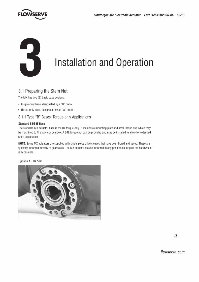
3.1.1 Type “B” Bases: Torque-only Applications
Standard B4/B4E BaseThe standard MX actuator base is the B4 torque-only. It includes a mounting plate and steel torque nut, which may be machined to fit a valve or gearbox. A B4E torque nut can be provided and may be installed to allow for extended stem acceptance.
NOTE: Some MX actuators are supplied with single piece drive sleeves that have been bored and keyed. These are typically mounted directly to gearboxes. The MX actuator maybe mounted in any position as long as the handwheel is accessible.
Figure 3.1 – B4 base

Limitorque MX Electronic Actuator FCD LMENIM2306-06 – 10/13
16
Figure 3.2 – B4E base
Figure 3.3 – Exploded view of B4/B4E base (MX-05 shown)
Torque nut
Retaining ring
Baseplate
MX base
Drive sleeve
Disassembly 1. Remove the retaining ring (B4 base) or spiral-wound ring (B4E base) that retains the torque nut in the drive sleeve.
2. Remove the torque nut. If the torque nut is difficult to remove, insert a suitable device into the drive sleeve through bore and gently tap it loose from the handwheel end.
3. Machine the torque nut to suit the valve stem or gearbox input shaft (see LMENSS2326, MX Performance and Dimensions for maximum stem capacity). Ensure sufficient clearance for a smooth, sliding fit.
Reassembly1. Clean the torque nut thoroughly and lightly grease.
2. Replace the torque nut in the drive sleeve. Ensure the torque nut meshes with the drive lugs.
3. Refit the retaining ring (B4 base) or spiral-wound ring (B4E base).
Optional B1 Base (not available for MX-85, MX-140 and MX-150)
An optional torque base assembly may be added to allow for a greater stem acceptance. This base is supplied with a fixed bore and key as defined by ISO 5210.

17
Limitorque MX Electronic Actuator FCD LMENIM2306-06 – 10/13
flowserve.com
Disassembly No disassembly is required since the torque nut has been machined to an international standard. Clean the bore and lightly grease.
Figure 3.4 – B1 base
NOTE: Fill base with a Lithium based EP0 grease.
Figure 3.5 – Exploded view of B1 base
Housing, torque/thrust
Pipe plug
Washer (M4) Socket head cap screw (M4 x 8)
Socket head set screw
Retainer, bearing
Pilot, torque/thrust
Bearing
Torque nut (B1)
Socket head cap screw (M8 x 20)
Pipe plug
MX-05 B1 MX-40 B1
Thrust nut assembly
3.1.2 Type “A” Bases: Thrust-only Applications
Standard A1/A1E BaseThe standard MX actuator thrust base is the A1, and may be bolted directly to the actuator. The thrust base contains a bronze alloy thrust nut that may be machined to suit the valve stem.
An A1E (extended) thrust nut can be provided and may be installed to reach shorter stems.
Figure 3.6 – A1 base
Disassembly – Units MX-05/10/20/40Refer to Figure 3.7.
Disassembly of the main housing from the base may be recommended to allow the base to remain on the valve if the actuator must be removed for service.

Limitorque MX Electronic Actuator FCD LMENIM2306-06 – 10/13
18
Pilot removalMX-10/20: Remove the screw and washer holding the valve pilot to the thrust base and remove pilot.
MX-40: Turn counterclockwise (CCW) and remove.
Thrust bearing and nut removal1. Remove the first set of thrust washers and bearing.
2. Remove stem nut.
NOTE: The thrust washers, bearing, and thrust nut may be removed at the same time. The second set of thrust washers and bearing does not have to be removed.
3. Machine the thrust nut to suit the valve stem. Ensure sufficient clearance to avoid unnecessary wear and heating during operation.
Reassembly – Units MX-05/10/20/40Refer to Figure 3.7.
1. Clean the thrust nut, washers, and bearing(s) thoroughly.
2. Slide second set of thrust washers and bearing in place if removed.
NOTE: Order of assembling thrust washers and bearing must be as follows: washer, thrust bearing, washer.
Pilot installationMX-05/10/20: Slide pilot into thrust base assembly and secure with washer and screw. Tighten fully.
MX-40: Place pilot into thrust base and turn clockwise (CW) until pilot is tight.
NOTE: Fill base with Nebula EP 0, Conoco Conolith EP 00, Mobil SHC 632, Dynalife-L-EP0, Triton ELL, or Lithium based EP0 grease.
Disassembly – Units MX-85Refer to Figure 3.8.
Disassembly of the main housing from the base may be recommended to allow the base to remain on the valve if the actuator must be removed for service.
Thrust base mounting plate removalRemove the six socket head cap screws holding the valve mounting plate to the thrust base housing and remove mounting plate.
Figure 3.7 – Exploded view of A1/A1E base (MX-05/10/20/40 only)Housing
Socket head cap
Socket head cap screw
Washer
Quad ring
Thrust washer
Pipe plug
Thrust Nut
Thrust washer
O-ring
Thrust pilot
Quad ring
Needle bearing
Thrust base standard nut
Thrust base extended nut

19
Limitorque MX Electronic Actuator FCD LMENIM2306-06 – 10/13
flowserve.com
Thrust bearing and nut removal1. Remove the first set of thrust washers and bearing.
2. Remove stem nut.
NOTE: The thrust washers, bearing, and stem nut may be removed at the same time. The second set of thrust washers and bearing does not have to be removed.
3. Machine the stem nut to suit the valve stem. Ensure sufficient clearance to avoid unnecessary wear and heating during operation.
Reassembly – Units MX-85Refer to Figure 3.8.
1. Clean the stem nut, washers, and bearing(s) thoroughly.
2. Slide second set of thrust washers and bearing in place if removed.
3. Install stem nut. Lubricate thoroughly.
4. Install first set of thrust washers and bearing.
NOTE: Order of assembling thrust washers and bearing must be as follows: washer, thrust bearing, washer.
NOTE: Fill base with Nebula EP 0, Conoco Conolith EP 00, Dynalife-L-EP0, Mobil SHC 632, Triton ELL, or Lithium based EP0 grease.
Thrust baseplate installationMount baseplate to thrust base housing and install the six socket head cap screws to the proper torque per Table 3.1.
Table 3.1 – Hardware and torque for thrust base mounting
Screw SizeTorque
ft-lb N m
M8 or 5⁄16 in. (8 mm) 12-14 16-19
M10 or 3⁄8 in. (9 mm) 25-30 33-40
M12 or 1/2 in. (13 mm) 40-50 53-67
M16 or 5⁄8 in. (16 mm) 90-100 122-135
M20 or 3/4 in. (19 mm) 180-200 244-271
NOTE: Screw mounting torque for mounting thrust base to main housing or thrust baseplate to thrust base housing.

Limitorque MX Electronic Actuator FCD LMENIM2306-06 – 10/13
20
Figure 3.8 – Exploded view of thrust base (MX-85 only)
Section A-A View show n
with standard nut
Section A-A View show n
with extended nut
A
A
Socket head cap screw s
Baseplate
Thrust washer
Thrust bearing
Quad ring
Thrust nut
Thrust bearing
Socket head cap screw s
Housing
Thrust washer
Pipe plug
O-ring
Quad ring
Disassembly – Units MX-140/MX-150Refer to Figure 3.9.
Disassembly of the main housing from the base may be recommended to allow the base to remain on the valve if the actuator must be removed for service.
Pilot removalRemove the two screws and washers holding the valve pilot to the thrust base and remove pilot.
Thrust bearing and nut removal
1. Remove the first set of thrust washers and bearing.
2. Remove stem nut.
NOTE: The thrust washers, bearing, and stem nut may be removed at the same time. The second set of thrust washers and bearing does not have to be removed.
3. Machine the stem nut to suit the valve stem. Ensure sufficient clearance to avoid unnecessary wear and heating during operation.
Reassembly – Units MX-140Refer to Figure 3.9.
1. Clean the stem nut, washers, and bearing(s) thoroughly.
2. Remove pipe plug.
3. Slide second set of thrust washers and bearing in place if removed.
4. Install stem nut. Lubricate thoroughly.
5. Install first set of thrust washers and bearing.
6. Install pipe plug.
NOTE: Order of assembling thrust washers and bearing must be as follows: washer, thrust bearing, washer.
NOTE: Fill base with Nebula EP 0, Conoco Conolith EP 00, Dynalife-L-EP0, Mobil SHC 632, Triton ELL, or Lithium based EP0 grease.

21
Limitorque MX Electronic Actuator FCD LMENIM2306-06 – 10/13
flowserve.com
Pilot installationSlide pilot into thrust base assembly and secure with the two washers and screws. Tighten fully.
3.1.3 Type “BL” Drive: Splined Drive ApplicationSteel alloy splined nuts are provided to a standard involute spline category for rising and rotating stem valves per customer requirements. Disassembly and reassembly is the same as the B4 base and the torque nut. See Section 3.1.1, Type “B” Bases: Torque-only Applications.
Figure 3.9 – Exploded view of thrust base (MX-140/MX-150 only)
Socket head cap screw s
Housing
Thrust bearing
Quad ring
Thrust nut
Thrust washers
Thrust bearing
O-ring
Socket head cap screw s
Washers
Thrust pilot
Pipe plug
Pipe plug
Section A-A View shown with
standard nut
Section B-B View shown with
extended nut A
B
B A
Quad ring
Thrust washers
3.2 Mechanical Installation Onto Valve or GearboxNOTE: Refer to MX Maintenance and Spare Parts bulletin (LMENIM2314) for more detailed instructions.
Before installing the actuator onto a valve or gearbox, check the following to ease installation:
• Verify that mounting flange is suited dimensionally to mate with the actuator base. Ensure that it is perpendicular to the valve stem or gearbox input shaft.
• Ensure the stem nut mates with the valve stem or input shaft. For screwed nuts, it is advisable to run the stem nut down the entire length of the stem to check for tightness. Keyed or splined shafts should exhibit a smooth, sliding fit with the key installed.
• Ensure there is adequate engagement of the stem nut with the valve stem or input shaft when mounted. Generally, the minimum length of engagement is 1.5 times the diameter of the stem.
• Verify that mounting studs or bolts are the correct length to suit the thickness of the mounting plate.
• Verify hardware specifications for English style:
• Socket head cap screw per ASTM A 574 and ANSI 18.3.
• Hex head cap screw per SAE J429 Grade 5.
• Verify hardware specifications for metric style: hex and socket head cap screws per Property Class 12.9.
• Clean and lubricate the valve stem or input shaft.
• Ensure adequate lifting facilities and slings are available at the installation site.
NOTE: Do not use the handwheel to lift the actuator.

Limitorque MX Electronic Actuator FCD LMENIM2306-06 – 10/13
22
3.2.1 Mounting (Type “B” Bases): Torque-onlyRefer to Figures 3.1 - 3.5.
1. Ensure torque nut is secured inside actuator drive sleeve with retaining ring.
2. Lower actuator onto the valve or gearbox stem. Align the stem nut key and keyway with valve or gearbox stem key seat.
3. Verify that the actuator and valve mounting adapter flanges mate correctly.
4. Secure the actuator to the valve mounting adapter with mounting bolts.
3.2.2 Removal (Type “B” Bases): Torque-onlyRefer to Figures 3.1 – 3.5.
1. Remove the bolts that secure the actuator to the valve mounting adapter. If type B1 base is used in addition to the standard type B4 baseplate, you may leave the B1 base attached to the actuator and remove as a unit.
2. Lift the actuator from the actuator mounting adapter.
3.2.3 Mounting (Type “A” Bases): Thrust-onlyRefer to Figures 3.6 – 3.9.
1. The following are two options for mounting the type A base actuator:
a. If the type A thrust base was removed from the valve mounting adapter, replace the thrust base onto the valve mounting adapter. Ensure the thrust base stem nut has the lugs positioned upward to engage with the drive sleeve slots when the actuator is reinstalled. Rotate the bronze nut while holding the base steady.
or
b. If the thrust base is installed on the valve mounting adapter, proceed to step two.
2. Lower the actuator along the threaded valve stem and onto the valve mounting plate. Ensure the thrust base stem nut lugs properly engage and align with the drive sleeve slots.
3. Install the bolts to secure the actuator to the thrust base assembly.
3.2.4 Removal (Type “A” Bases): Thrust-only1. Remove the bolts that secure the actuator to the thrust base assembly.
2. Remove the type A thrust base by removing the bolts that secure the actuator to the valve mounting adapter.
or
Leave the type A thrust base mounted to the valve mounting adapter until ready to remount the actuator. The thrust base will maintain valve position provided that the valve stem threads are locking.
3. Lift the complete actuator from the thrust base.
23
Limitorque MX Electronic Actuator FCD LMENIM2306-06 – 10/13
flowserve.com
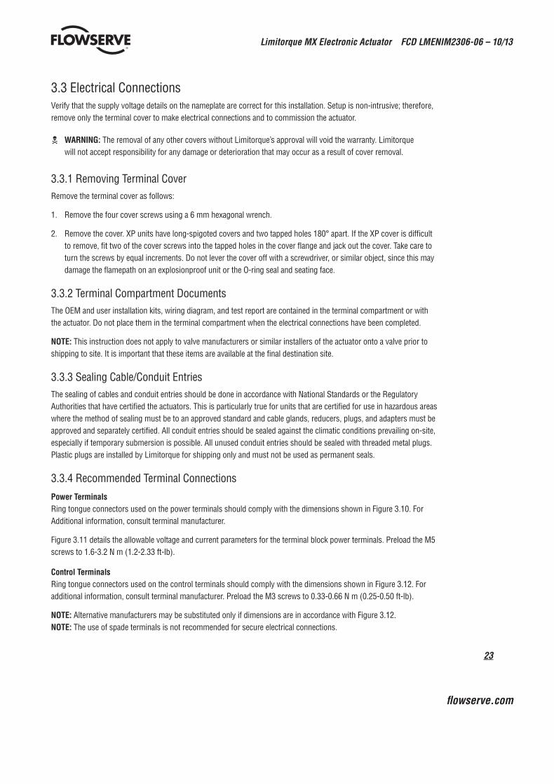
3.3 Electrical ConnectionsVerify that the supply voltage details on the nameplate are correct for this installation. Setup is non-intrusive; therefore, remove only the terminal cover to make electrical connections and to commission the actuator.
c WARNING: The removal of any other covers without Limitorque’s approval will void the warranty. Limitorque will not accept responsibility for any damage or deterioration that may occur as a result of cover removal.
3.3.1 Removing Terminal CoverRemove the terminal cover as follows:
1. Remove the four cover screws using a 6 mm hexagonal wrench.
2. Remove the cover. XP units have long-spigoted covers and two tapped holes 180° apart. If the XP cover is difficult to remove, fit two of the cover screws into the tapped holes in the cover flange and jack out the cover. Take care to turn the screws by equal increments. Do not lever the cover off with a screwdriver, or similar object, since this may damage the flamepath on an explosionproof unit or the O-ring seal and seating face.
3.3.2 Terminal Compartment DocumentsThe OEM and user installation kits, wiring diagram, and test report are contained in the terminal compartment or with the actuator. Do not place them in the terminal compartment when the electrical connections have been completed.
NOTE: This instruction does not apply to valve manufacturers or similar installers of the actuator onto a valve prior to shipping to site. It is important that these items are available at the final destination site.
3.3.3 Sealing Cable/Conduit EntriesThe sealing of cables and conduit entries should be done in accordance with National Standards or the Regulatory Authorities that have certified the actuators. This is particularly true for units that are certified for use in hazardous areas where the method of sealing must be to an approved standard and cable glands, reducers, plugs, and adapters must be approved and separately certified. All conduit entries should be sealed against the climatic conditions prevailing on-site, especially if temporary submersion is possible. All unused conduit entries should be sealed with threaded metal plugs. Plastic plugs are installed by Limitorque for shipping only and must not be used as permanent seals.
3.3.4 Recommended Terminal Connections
Power TerminalsRing tongue connectors used on the power terminals should comply with the dimensions shown in Figure 3.10. For Additional information, consult terminal manufacturer.
Figure 3.11 details the allowable voltage and current parameters for the terminal block power terminals. Preload the M5 screws to 1.6-3.2 N m (1.2-2.33 ft-lb).
Control TerminalsRing tongue connectors used on the control terminals should comply with the dimensions shown in Figure 3.12. For additional information, consult terminal manufacturer. Preload the M3 screws to 0.33-0.66 N m (0.25-0.50 ft-lb).
NOTE: Alternative manufacturers may be substituted only if dimensions are in accordance with Figure 3.12.NOTE: The use of spade terminals is not recommended for secure electrical connections.

Limitorque MX Electronic Actuator FCD LMENIM2306-06 – 10/13
24
Figure 3.10 – Power terminal connector size limitations
NOT TOEXCEED 15
NOT TOEXCEED 6.5
NOT TOEXCEED 9.8
TO BE SIZEDFOR M5 SCREW
SPADE AND SNAPTERMINALS
MAX. THICKNESS = 1.6 mm
TO BE SIZEDFOR M5 SCREW
NOT TOEXCEED 9.6
NOT TOEXCEED 15
RING TERMINAL
NOT TOEXCEED 3.5
FLANGEDSPADE TERMINAL
Figure 3.11 – Terminal block rating; power terminals Description L1 L2 L3
STD Rating
30 AMP 20 AMP 15 AMP
8 Awg/10 mm2 10 Awg/6 mm2 14 Awg/2.5 mm2
600 VAC RMS 150 VDC
Increased Safety Rating
27 AMP 18 AMP 13.5 AMP
8 Awg/10 mm2 10 Awg/6 mm2 14 Awg/2.5 mm2
500 VAC RMS 150 VDC
Note: Ratings will be the same for L1, L2, or L3, e.g., if 10 Awg is selected, then L1, L2 and L3 will have the same limitations.
Figure 3.12 – Control terminal connector size limitations
NOTE: All dimensions are in mm.
NOTE: Limitorque recommends the use of the following connector for optimum results: Thomas and Betts #RZ22-6.
NOTE: Alternative manufacturers may be substituted only if the dimensions are in accordance with Figure 3.12.
Table 3.2 lists the maximum allowable voltage and current parameters for the terminal block control terminals.
NOT TOEXCEED 4.0
NOT TOEXCEED 7.6
NOT TOEXCEED 5
TO BE SIZEDFOR M3 SCREW
SPADE AND SNAPTERMINAL
MAX. THICKNESS = 1.0 mm
NOT TOEXCEED 5
TO BE SIZEDFOR M3 SCREW
RING TERMINAL
NOT TO EXCEED 8.2
3X M5 SCREW
3X M5 SPRING WASHER 54X M3 SPRING
WASHER
54X M3 SCREW
FIGURE 3.13THE USE OF THE SPRING WASHERS ARE REQUIRED
ON INCREASED SAFETY APPLICATIONS.

25
Limitorque MX Electronic Actuator FCD LMENIM2306-06 – 10/13
flowserve.com
Table 3.2 – Terminal block rating; control terminals
Low Voltage Row STD Rating Increased Safety Rating
1 points 1-16, 50 Volt 0.5 AMP AC RMS 0.45 AMP AC RMS
2 points 17-35, 125 Volt 0.5 AMP AC RMS 0.45 AMP AC RMS
3 and 4 points 36-54, 250 Volt 5 AMP AC RMS 4.5 AMP AC RMS
3.3.5 Termination of CablesAll terminations should be made with insulated ring terminals using the appropriate crimping tool. See Figures 3.10 and 3.11 for power terminal connection recommendations. See Figure 3.12 and Table 3.2 and 3.3 for control terminal connection recommendations.
3.3.6 Cable ConnectionsSee Figure 3.14 for connection information.
1. Connect the main power supply cables, including the earth/ground wire using the M5 screws provided.
2. Attach the earth/ground wire to the separate screw on the inside of the terminal compartment.
3. Use the M3 screws installed in the terminal block to connect the control cables in accordance with the wiring diagram and the project specification.
4. Ensure that all connections are tight, including any spare termination screws that have not been used.
NOTE: A “Customer Connection(s) Diagram” sticker is attached to the interior of the terminal compartment cover. This may be removed and user termination numbers inscribed adjacent to Limitorque’s terminal block numbers for field connection reference. The diagram may also be used to assist in locating the terminal block positions. Service and factory contacts are contained on the sticker.
Certification is based on the use of appropriately rated wire for the application. Installation shall be in accordance with the current issue of the applicable national and or local electric code or regulations.
Table 3.3 – Required ratings for external wires
Up to Use wire rated at least
40°C Ambient 75°C
55°C Ambient 90°C
60°C and 65°C Ambient1 105°C
Note 1: Refer to unit nameplate.
3.3.7 Network InstallationsThe Limitorque MX offers a number of network options: DDC-Modbus, Foundation Fieldbus H1, Profibus DP_V1, Profibus PA, and DeviceNet.
Ensure that the network cable type is Belden 3074F, Belden 3105, Belden 9841 or another cable that is within 5% of the following specifications.
• Nominal impedance: 120 ohms @ 1 MHz
• Line to shield capacitance: 23.0 pF/ft (75.5 pF/m)
• Line to line capacitance: 12.8 pF/ft (42.0 pF/m)
Using other cables may result in decrease of internodal distance and/or an increase in communication error.
Limitorque MX Electronic Actuator FCD LMENIM2306-06 – 10/13
26
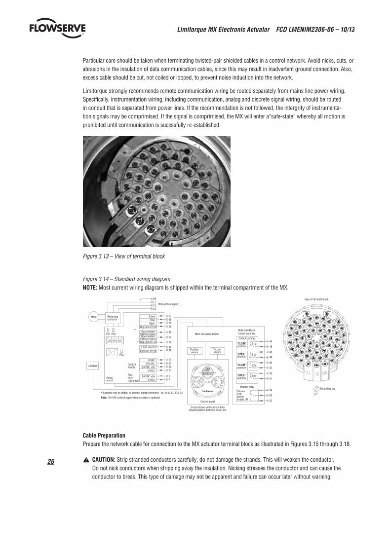
Particular care should be taken when terminating twisted-pair shielded cables in a control network. Avoid nicks, cuts, or abrasions in the insulation of data communication cables, since this may result in inadvertent ground connection. Also, excess cable should be cut, not coiled or looped, to prevent noise induction into the network.
Limitorque strongly recommends remote communication wiring be routed separately from mains line power wiring. Specifically, instrumentation wiring, including communication, analog and discrete signal wiring, should be routed in conduit that is separated from power lines. If the recommendation is not followed, the intergrity of instrumenta-tion signals may be comprimised. If the signal is comprimised, the MX will enter a“safe-state” whereby all motion is prohibited until communication is sucessfully re-established.
Figure 3.13 – View of terminal block
Figure 3.14 – Standard wiring diagramNOTE: Most current wiring diagram is shipped within the terminal compartment of the MX.
Cable Preparation Prepare the network cable for connection to the MX actuator terminal block as illustrated in Figures 3.15 through 3.18.
a CAUTION: Strip stranded conductors carefully; do not damage the strands. This will weaken the conductor. Do not nick conductors when stripping away the insulation. Nicking stresses the conductor and can cause the conductor to break. This type of damage may not be apparent and failure can occur later without warning.
Configurable SET-UP to give; Either -Contact closed-Valve OPEN S -Contact opened-Valve CLOSE OR : -Contact closed-Valve CLOSES -Contact opened-Valve OPEN S
3-WIRE 4-WIRE INHIBIT ESD
5
7
5
6
7
9
10
21
INTERNAL SUPPLY
110V AC
8
5
7
12
8
11
5
6
7
8
12
8
11
5
7
13
8
14
5
6
7
13
8
14
8 8
9
10
21
12 12
9
10
21
13 13
8
14
8
14
5 CLOSE
STO P 6
OPEN 7
CONTROL COMMON 8
11 0V AC
110V AC 12
+24V DC 13
0V DC 14
10 OPEN INHIBIT
CLOSE INHIBIT 9
ESD 21 FUNCTIO N POIN T
TERMINAL
EXTERNAL SUPPLY
24 TO 110 VOLT
AC/D C
8
11
8
11
AC/DC 0V
AC/D C 24-110V
AC/D C 0V
AC/DC 24-110V
AC/D C 0V
AC/D C 24-110V
AC/D C 0V
AC/DC 24-110V
EXTERNAL SUPPLY
Configurable SET-UP to give; Either -OPEN/CLOSE push-to-run (inching) mode OR -OPEN/CLOSE push and release (maintained) mode with mid- travel reversal (Stop before reverse)
mid-travel stop reversal and with mid-travel (maintained) MODE Push-and-release OPEN/STOP/CLOSE
close contacts maintained open or interlock/inhibit on SET-UP to give; Configurable during
CLOSED/OPEN/STOP/IGNORED maintained ESD signal: ACTIONS on receipt of a to give following modes of Configurable during SET-U P
REMOTE WIRING CONNECTIONS
7
8
2-WIRE
7
12
8
11
7
13
8
14
AC/D C 0V
AC/D C 24-110V
OUTPUT SWITCH CONTACT DEVELOPMENT
VALVE POSITIO N
FULL CLOSE
FULL OPEN FUNCTIO N
CLOSE LIMIT
AS4 OPEN LIMIT
AS 3 CLOSE LIMIT
OPEN LIMIT AS1 AS2
SWITCH OUTPU T
INTERNAL SUPPLY 24V DC
Grounding lug
View of terminal block
Reversing contactor
Close Stop Open
Dig Com #1-Ve
Close inhibit/ interlock Input 1
interlock Input 2Open inhibit/
Dig Com #2-Ve
0 VAC 110 VAC
24 VDC +Ve 0 VDC
24 VDC +Ve 0 VDC
272625
35
28
29
34
2423
2122
76
L1 L2 L3
FS1 FS2
FS3
LimiGard
Motor
board Power
PE
Three-phase supply
Controlsupply
Aux.input(Optional)
*
E.S.D. Input 0Dig Com #3-Ve 32
30Position sensor
44
45
48
49
46
47
50
51
S1a
S1b
S2a
S2b
“ CLOSE ” position
“ OPEN ” position
54
53
52
Show n with power supply off
Control panel
Torque sensor
Monitor relay
Circuit shown with valve in fully closed position and with power off.
Main processor board Status feedback output switches
Default setting
“ CLOSE ” position
“ OPEN ” position
CLOSE STOP
OPEN (YES) REMOTE
LOCAL (NO)
Limitorque *Jumpers may be added to connect digital commons - pt. 28 & 29, 31& 32
Note: 110 VAC control supply from actuator is optional.

27
Limitorque MX Electronic Actuator FCD LMENIM2306-06 – 10/13
flowserve.com
1. Remove 2 to 3 in. (5 to 8 cm) of the outer plastic jacket as shown in Figure 3.15. Do not cut or nick the drain wire or the insulated conductors.
Figure 3.15 – Removing outer plastic jacket
2. Separate the cable parts. Unbraid the braided shield and peel back the foil shield to the same point where the outer jacket was removed as shown in Figure 3.16.
3. Cut away the braided shield and the foil shield. Strip the insulation from the conductors approximately 1/2 inch (1 cm) as shown in Figure 3.17.
4. Apply heat shrink tubing to insulate the drain wire and to provide stress relief to the cable.
5. Install ring tongue connectors as shown in Figure 3.18.
a CAUTION: Do not melt the insulation.
6. Connect the network cables to the MX actuator terminal block per Table 3.4 and appropriate wiring diagram. Table 3.3 details a connection for the loop topology.
Figure 3.16 – Separating cable parts

Limitorque MX Electronic Actuator FCD LMENIM2306-06 – 10/13
28
Figure 3.17 – Stripping conductors and applying heat shrink tubing
Figure 3.18 – Ring tongue connectors
Table 3.4 – Loop topology connections
Terminal Block Number DDC
4 DATA-A1* (-)
5 DATA-A1 (+)
14 DATA-A2* (-)
13 DATA-A2 (+)
3 Surge Protection
In terms of voltage, DATA is negative with respect to DATA*.
NOTE: Surge protection must be grounded to be effective.
NOTE: Ground each segment of the cabling at only one point to prevent ground loops, which can affect system performance. Verify the actuator is properly grounded.
Limitorque defines an effective local earth ground as the M3 taps on the housing next to the terminal block. See figure 3.21.
NOTE: Safety ground may not be disturbed.
NOTE: Shielding is not sufficient to prevent induction of stray voltages onto signal leads from the power lines.
A network wiring diagram for a loop is shown in Figure 3.20.

29
Limitorque MX Electronic Actuator FCD LMENIM2306-06 – 10/13
flowserve.com
After installation is complete and prior to operation, inspect the network cable and its connection to each field unit for the following:
There should not be:
• Nicks in the insulation—this can cause a short to the grounded shield.
• Cut strands in a stranded conductor—this can cause a poor connection and eventually an open circuit.
• Cable armor shorted to the cable shield/drain wire—this may not be at ground potential and could be subject to lightning surges.
• Shield/drain wire grounded at more than one end of each cable segment (the section between each adjacent actuator on the loop). This will avoid ground loop problems.
• Ground/earth connection except at true ground potential and effective at all times.
3.3.8 Foundation Fieldbus InstallationEnsure that the Foundation Fieldbus cable type is Belden 3076F, or another cable that is within 5% of the following specifications.
• Characteristic impedance: 100 ohms @ 31.25 kHz
• Resistance, each wire: 7.32 ohms/1000 ft
• Attenuation: 0.914 dB/1000 ft @ 39 kHz
• Capacitative Unbalance: 3.6 pF/ft
Using other cables may result in decrease of internodal distance and/or an increase in communication error.
Particular care should be taken when terminating twisted-pair shielded cables in a FF control network. Avoid nicks, cuts, or abrasions in the insulation of data communication cables, since this may result in inadvertent ground connection. Also, excess cable should be cut, not coiled or looped, to prevent noise induction into the network.
Cable Preparation Prepare the network cable for connection to the MX actuator terminal block as follows in Figure 3.15 through 3.18. Table 3.5 details connections for Foundation Fieldbus.
Table 3.5 – Foundation fieldbus connections
Terminal Block Number FF Function
4 DATA (-)
5 DATA (+)
The shield must be connected to ground or earth at only one place. The cable shield is generally grounded at the power conditioner.
Reference the Fieldbus Foundation Application Guide 31.25 kbit/s Wiring and Installation guide for more information on network wiring.
a CAUTION: Strip stranded conductors carefully; do not damage the strands. This will weaken the conductor. Do not nick conductors when stripping away the insulation. Nicking stresses the conductor and can cause the conductor to break. This type of damage may not be apparent and failure can occur later without warning.

Limitorque MX Electronic Actuator FCD LMENIM2306-06 – 10/13
30
3.3.9 Network Wiring – Profibus DP/PA InstallationProfibus DP is based on RS 485 communication. The standard EN 50170 specifies the cable for use with Profibus DP.
The following specifications need to be fulfilled by the Profibus cable:
Table 3.6 – Profibus cable specifications
Parameter Type – Profibus DP
Impedance 135 to 165 ohm/3 to 20 MHz
Capacity < 30 pF/m
Resistance < 110 ohm/km
Wire gauge > 0.64 mm
Conductor area > 0.34 mm2
The Profibus DP cable is a shielded twisted pair cable.
In general, there are two different types of cables available. The most commonly used cable has solid wire for the Profibus line. When there is a need for more flexiblity (bending) and higher environmental resistance, a cable with stranded wire for the Profibus line and special jackets shall be used. Limitorque recommends the use of:
• Belden 3079A Specifications, 22 AWG, shielded, solid two conductor
Key Specifications• Capacitance/ft = 8.5 pF
• Nominal Impedance (ohms) – 150.0
Network Wiring - Profibus PAPlease refer to IEC 61158 & ANSI/ISA S.50.02 Part 2-1992 for network wiring guidelines. Refer to Table 3.5 for connections.
3.3.10 Network Wiring – DeviceNet DeviceNet is a CAN-based protocol that uses five wires including a shield. Two of the conductors are used for 24 VDC power and up to 8 amps (4 amps for NEC Class 2) may be passed along the hi-way from a suitable power source. Two conductors are used for the CAN bus signals, CAN_H and CAN_L, which are usually smaller in diameter. Flowserve recommends Belden 3082A cable for connecting to a DeviceNet network. The specifications for this cable are preferred.
Table 3.7 – DeviceNet cable specifications
Belden Part No.
AWG (Stranding) dia. Inches Nom. DCR
Insulation material
(color code)
Nominal O.D.
Nom Impedance
(ohms)
Nominal Capacitance
Test Frequency
(MHz)
Maximum Attenuation
dB/100ft
3082A
2 – 15 AWG (19 x 28) 3.6 ohm/1000 ft
11.8 ohm/km
Power pair (Black/Red)
12.2 mm 120 12.0 pF/ft 0.125 0.5 1
0.13 0.25 1.36 2 – 18 AWG (19 x 30)
6.9 ohm/1000 ft 22.7 ohm/km
Data pair (Blue/White)
3084A
2 – 22 AWG (19 x 34) 17.5 ohm/1000 ft
57.4 ohm/km
Power pair (Black/Red)
7.2 mm 120 12.0 pF/ft
0.125 0.5 1
0.29 0.50 1.70 2 – 18 AWG (19 x 36)
28.0 ohm/1000 ft 91.9 ohm/km
Data pair (Blue/White)

31
Limitorque MX Electronic Actuator FCD LMENIM2306-06 – 10/13
flowserve.com
Please refer to Table 3.4 for connections.
3.3.11 HART Installation WiringHART, or Highway Addressable Remote Transducer, is a digital signal over analog 4-20 mA communications. Please consult LMENIM2340, HART Network Installation and Operation Manual for correct wiring preparation and installation.
3.3.12 Replacing Terminal CoverVerify that the O-ring seal and spigot joint are clean and in good condition. Lightly coat these items with mineral-based lubricant before replacing the terminal cover and four retaining screws.
3.3.13 External Earth/Ground Connections In order to help meet the local electric codes of the installation, one external connection point is provided on the main gear housing for the attachment of earth/ground cables. See Figure 3.21. This is in addition to the ground connection inside the terminal compartment.
3.4 Terminal Block Shield InstallationSTEP 1
Remove terminal block cover.
STEP 2
Use Qty of 2 screws from terminal block or from end users bag to attach shield.
STEP 3
Remount terminal block cover.
Figure 3.19 – Terminal block shield
M3 X 5 SELF LOCK SCREW
USE QTY. OF TWO (2)TO MOUNT SHIELD.
USE 2 SCREWS FROMTERMINAL BLOCK OR
FROM END USERS BAG. SHIELD-TERMINAL BLOCK
3.5 Commissioning the ActuatorBefore attempting to commission the actuator, verify that the actuator is installed correctly on the valve and main power is “ON.”
After making the initial electrical connections detailed in Section 3.3, Electrical Connections, the MX actuator may be commissioned without removing any covers. No special tools are required. Configuration is accomplished through the use of the LCD and the control knobs mounted on the control panel.
For positioning the actuator:1. Place the red knob in the “LOCAL” position.
2. Move the black knob to the “OPEN” or “CLOSE” position.
Limitorque MX Electronic Actuator FCD LMENIM2306-06 – 10/13
32
For configuring the actuator:1. Place the red knob in the “STOP” position.
2. Move the black knob to the “YES” or “NO” position and release to answer questions appearing on the LCD display.
The OPEN and CLOSE position limits must be set after the actuator has been mounted on the valve. See Section 3.5.4, Setting Position Limits. All other actuator parameters are factory-set either in accordance with a Limitorque standard set of default values (see Section 3.5.1, Default Configuration Set) or the requirements specified with the purchase order. Reconfirm these preconfigured settings prior to placing the actuator into service since the requirements of the application may have changed after the manufacture of the actuator. See Section 3.5.2, View the Existing Settings.
3.5.1 Default Configuration SetUnless otherwise specified, actuators are shipped with the following configuration:
• When Open stopped by position limit; Open seating (position)
• When Close stopped by position limit; Close seating (position)
• Maintained local control; Mode (maintained)
• Clockwise to close; Close direction (CW)
• ESD – User configurable inputs; default is “OFF”
• Inhibits on; Inhibit status (Default = OFF)
• Remote control – three-wire maintained
• Password – 100
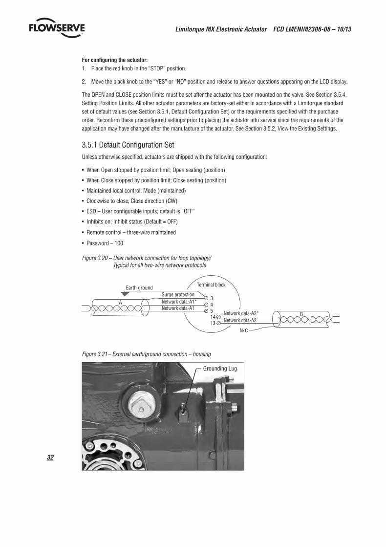
Figure 3.20 – User network connection for loop topology/ Typical for all two-wire network protocols
Surge protection Network data-A1* Network data-A1
N/ C
Earth ground Terminal block
3451413
A
B Network data-A2* Network data-A2
Figure 3.21 – External earth/ground connection – housing
Grounding Lug

33
Limitorque MX Electronic Actuator FCD LMENIM2306-06 – 10/13
flowserve.com
Table 3.8 – Default configurations
Modutronic OptionProportional band – 15%Deadband – 2%Polarity – 20 mA = OpenAction on loss of signal = Close
Modbus RTU protocol9600 baudAnalog scale = 0-100Proportional band – 15%Deadband – 2%Offset – 0 mAFF Option and PB Option
Analog scale = 0-100Proportional band – 15%Deadband – 2%
If the default configuration is acceptable, no further configuring is necessary. If any default setting needs to be changed, see Section 4, Customizing the Actuator.
3.5.2 View the Existing Settings All the existing setup data may be viewed on the LCD display by following a simple step-by-step dialog that may be selected in the following languages: English (default), Spanish, French, German, Italian, Portuguese, Russian, Malay, Mandarin, and Katakana.
1. Enter the “SETUP” mode as detailed in Section 2.1.1, Entering the Setup Mode.
2. Select the dialog language. Toggle “NO” to scan the language options. Select “YES” when the desired language appears on the LCD.
3. Scan menu selections on LCD and select “YES” when “VIEW SETTINGS” appears.
4. Scan through the series of displays and answer “YES” or “NO” at the appropriate prompts. Each display shows the state or value of the existing settings. See Figure 3.22.
NOTE: The “VIEW SETTINGS?” mode can be accessed without entering a password, but no changes to the settings can be made in this mode.
3.5.3 Entering the Setup Mode To customize the actuator, view settings, or view diagnostics, the user must enter the “SETUP” mode. A three-digit password is required to customize the actuator. All actuators are supplied with the same default password (100). See Sections 4.2 and 4.3, Password Entry and New Password for entering and changing password. Main power must be applied to execute the setup procedure. It is recommended that the actuator be mounted to the valve before commis-sioning the actuator.
Enter the “SETUP” mode as follows:
1. Place the red knob in the “STOP” position.
2. Within 10 seconds, place the black control knob in the “YES” position, then the “NO” position, then again in the “YES” position (in quick succession—approximately one-two seconds).
3. The LCD will display “SETUP?” for 10 seconds. If no action is taken within the 10 seconds, the unit will return to “STATUS OK.”
4. Using the black knob, answer “YES” or “NO” to the questions appearing on the LCD display.
NOTE: While in the “SETUP” mode, if there is a lapse of 15 minutes from last action, the unit will return to the “SETUP?” display. Any changes that have been made will be stored.

Limitorque MX Electronic Actuator FCD LMENIM2306-06 – 10/13
34
5. When configuration is complete, answer “YES” to “EXIT SETUP?” or move the red knob from “STOP” to “LOCAL” or “REMOTE.”
After exiting the “SETUP” mode, all settings will automatically be saved to a non-volatile memory and retained, even when power is removed from the actuator. However, if power is removed from the unit while the unit is in “SETUP” mode, customization changes will be lost.
Figure 3.22 – View settings
VIEWVALVE SETTINGS?
1
VIEWSETTINGS?
YES
NO
NO
YESYES
VIEW FF?
NO
YES
NOTE 1: These optional displayswill not appear unless theoption has been purchased.
NOTE 2: If enabled.NO
YES
NO
YES
NO
YES
NO
YES
VIEWLOCAL CONTROL?
NO
YES
YES
YES
NO
VIEWPB/DP?
VIEW 2-SPEEDTIMERS?
VIEW STATUS & ALARM CONTACTS?
NO
YES
NO
YES
NO
YES
NO
SeeNOTE 1
SeeNOTE 1
SeeNOTE 1
YES
NO
1
YES
YES
NO
NONO
YES
YES
NO
VIEWANALOG OUT?
VIEWPB/PA?
VIEWDEVICENET?
SeeNOTE
1SeeNOTE
SeeNOTE
1
1
SeeNOTE
SeeNOTE
VIEWREMOTE MODE?
VIEW ESDOVERRIDES?
VIEWMONITOR RELAY?
VIEWINPUTS?
VIEWTORQUE BOOST?
VIEWTHERMOSTAT?
VIEWVALVE DATA?
VIEWPORTS?
YES
VIEW BACK-UP POWER?
VIEWUNIT DATA?
VIEWMODUTRONIC?
VIEW TORQUESETTINGS?
SeeNOTE 1
SeeNOTE 2
YES
YES
NO
SeeNOTE 1
YES
NO
NO
VIEW TORQUETIMER?
YES
NO
VIEWDDC?
3.5.4 Setting Position Limits
This section will advise how to configure end-of-travel limits.
The actuator’s position limits may be set by manual operation or electrical operation.
c WARNING: If the actuator will not move after setting the limits, the limits have been set incorrectly.
Set Close Position Limit (Handwheel Operation)1. Enter the “SETUP” mode as detailed in Section 2.1.1, Entering the Setup Mode.
2. Enter “POSITION SETUP?” routine.
3. From the “SET CLOSE POSITION LIMIT?” display, select “YES.” “CLOSE VALVE OK?” will be displayed on the LCD.
4. Engage manual override as detailed in Section 3.6.1, Manual Operation.
5. Ensure that the valve is fully closed.
6. Move the valve in the open direction for one handwheel turn to allow for coasting of the motor.
7. When the valve is positioned correctly, select “YES” again. The LCD will display “SAVE CLOSE LIMIT OK?”
8. Select “YES.”
The close position limit is now calibrated. Check the position limit setting as follows:
1. Move the valve in the open direction. The close lamp should extinguish with approximately one turn of the handwheel.

35
Limitorque MX Electronic Actuator FCD LMENIM2306-06 – 10/13
flowserve.com
2. Move the valve back in the close direction and check that the close lamp illuminates just before the full close posi-tion is reached (approximately 1/2 to 1 turn).
3. Select “YES” at the “SET OPEN POSITION LIMIT?” prompt.
4. Set Position Precision? The MX permits position to be reported to the User in either default mode of XXX% OPEN, or single precision mode of XXX.X% OPEN. This may be preferred in Modulating or other positioning applications such as network move-to, analog fail move-to, communication loss move-to, or ESD move-to.
If the calibration requires adjustment:
1. Select “NO” at the “SET OPEN POSITION LIMIT?” prompt.
2. Repeat the “SET CLOSE POSITION LIMIT?” routine.
NOTE: The green LED is the default setting for indicating the (CLOSE) position.
Set Open Position Limit (Handwheel Operation)1. From the “SET OPEN POSITION LIMIT?” display, select “YES.” “OPEN VALVE OK?” will be displayed on the LCD.
2. Engage manual override as detailed in Section 3.6.1, Manual Operation.
3. Ensure that the valve is fully open.
4. Move the valve in the close direction for one handwheel turn to allow for coasting of the motor.
5. When the valve is positioned correctly, select “YES” again. The LCD will display “SAVE OPEN LIMIT OK?”
6. Select “YES.”
The open position limit is now calibrated. Check the open position limit setting as follows:
1. Move the valve in the close direction. The open lamp should extinguish with approximately one turn of the handwheel.
2. Move the valve back in the open direction and check that the open lamp illuminates just before the full close posi-tion is reached (approximately 1/2 to 1 turn).
3. Select “YES” at the “SET OPEN POSITION LIMIT?” prompt or “NO” to exit “POSITION SETUP?” dialog.
If the calibration requires adjustment:
1. Select “NO” at the “SELECT CLOSE POSITION LIMIT?” prompt.
2. Repeat the “SELECT OPEN POSITION LIMIT?” routine.
NOTE: The red LED is the default setting for indicating the (OPEN) position.
Set Close or Open Position Limit (Electrical Operation)1. Enter the “SETUP” mode detailed in Section 2.1.1, Entering the Setup Mode.
2. Enter “POSITION SETUP?” routine.
3. During “CLOSE VALVE - OK?” or “OPEN VALVE - OK?,” move the red knob to “LOCAL” and use the “OPEN” and “CLOSE” switch.
Unit will only operate locally and only in the push-to-run configuration (Inching mode). This does not exit the startup routine—moving red selector knob back to “STOP” returns the user to the same message. This permits the valve to be placed at its travel limits and avoids the necessity to use the handwheel. The unit will run while the black knob is engaged with no stop limit when in this mode. Any previously set travel limits will be ignored.

Limitorque MX Electronic Actuator FCD LMENIM2306-06 – 10/13
36
1. Move the red knob to “LOCAL” and move the black knob in the intended direction. LCD display will read:
OR CLOSE VALVE RETURN TO STO P
OPEN VALVE RETURN TO STO P
2. Once the “CLOSE” or “OPEN” valve position limit has been reached, return the red knob to “STOP” and complete setting the “CLOSE” or “OPEN” position limit. See Figure 3.23.
NOTE: Once the travel limits have been set, the actuator may be operated electrically from the remote inputs. Local maintained operation is also permitted. Check the operation of the actuator to ensure that the torque and limit settings are satisfactory. Place the selector switch in “LOCAL” and rotate the “OPEN/CLOSE” switch to operate the actuator in the “MOTOR” mode.
a CAUTION: On some valves, position limits could be set adjacent to each other, so be careful that the Close and Open limits are set sufficiently apart to permit operation. If the limits are set adjacent to each other, an error message will be displayed: “KEEP OPEN(CLOSE) LIMIT?”
NO FURTHER MOVEMENT IS PERMITTED UNTIL THE ERROR IS CORRECTED.
Should the User elect to proceed with the setting, an error will be displayed on the screen after re-booting stating “IDENTICAL LIMITS”. THE ACTUATOR WILL NOT MOVE UNTIL THE ERROR IS CORRECTED.
Figure 3.23 – Position setup – electrical operation
“NO ” operatesclose direction
“YES” operatesopen direction
Enter “SETUP ” mode
OPEN VALVERETURN TO STOP
OPEN VALVEOK ?
SAVE OPENLIMIT OK?
SETUP?
CLOSE VALVERETURN TO STOP
SAVE CLOSELIMIT OK?
CLOSE VALVEOK ?
CLOSE VALVEOK ?
EXITSETUP?
100% OPENSTATUS OK?
SET CLOSEPOSITION LIMIT?
YES
YES YES2
YES
YES
YES YES YES2
NO NONO NO NO
YES1
NONO
NO
NO
STOP
STOPSTOP
LOCAL
Switch to
LOCAL
Switch to
OPEN VALVEOK ?
SET OPENPOSITION LIMIT?
YES
NONO
SET POSITIONPRECISION?
POSITIONXXX% OPEN?
YES
NONO
POSITIONXXX.X% OPEN?
NO
IDENTICAL LIMITSKEEP OPEN LIMIT?
YES
NO
IDENTICAL LIMITSKEEP CLOSE LIMIT?
YES
NO
YES
YES
YES1
NOTE 1: If open and close limits are not identical
NOTE 2: If open and close limits are identical
Moving the red knob from “STOP” to “LOCAL” or “REMOTE” automatically saves to non-volatile memory all the changes that have been made.

37
Limitorque MX Electronic Actuator FCD LMENIM2306-06 – 10/13
flowserve.com
3.6 Operating the MX Actuator
3.6.1 Manual OperationOperate the actuator with the handwheel as follows:
1. Depress the declutch lever and, at the same time, slowly rotate the handwheel until the clutch is fully engaged.
2. Release the lever and it will return to its original position. The clutch will be retained in the handwheel mode by spring-loaded latches.
Manual operation is now possible and the actuator can only be returned to motor operation by energizing the motor. Energizing the motor will trip the spring-loaded latch and allow the clutch to disengage from the handwheel and re-engage with the gear drive. To prevent unauthorized manual operation of the actuator, the declutch lever may be padlocked in “MOTOR” mode. A 1/2 inch size padlock is recommended.
3.6.2 Electrical OperationBefore applying power to the actuator, check that the supply voltage details on the nameplate are correct for this installation. An incorrect supply connected to the actuator terminals could cause fuses to blow or cause permanent damage to the electrical components in the unit. Phase rotation need not be checked since all units are supplied with an Autophase Correction feature. Apply power to the actuator but do not operate the actuator without first checking that it has been set up and configured correctly for its intended application.
Figure 3.24 – Declutch lever shows direction of engagement (MX-05 shown)
3.6.3 Local Control Once the position limits have been set (see Section 3.5.4, Setting Position Limits) and the default mode is the main-tained mode, the actuator can be controlled locally from the control panel.
1. Place the red selector knob in the “LOCAL” position.
2. Select “OPEN” or “CLOSE” via the black control knob.
If maintained control has been selected, the actuator will continue to run when this control knob is released. The actuator may be stopped at any time by placing the red selector knob in the “STOP” position, or the direction may be reversed or stopped using the black control knob.
If non-maintained control mode (inching) has been selected, the actuator can be inched to any intermediate position by holding the black control knob in the desired position, “OPEN” or “CLOSE,” for as long as necessary. The actuator will stop when the knob is released.

Limitorque MX Electronic Actuator FCD LMENIM2306-06 – 10/13
38
3.6.4 Remote Control Once the position limits have been set, and “REMOTE” mode is enabled:
1. Place the red selector knob in “REMOTE” to permit command control by a remote device. Local “OPEN/CLOSE” mode will be prevented.
2. Rotating the red selector knob to the “STOP” position will automatically stop the actuator regardless of the remote control signal unless ESD override has been selected. See Section 4.18, ESD (Emergency Shutdown) Overrides.
The red selector knob may be locked in or out of any of its three positions, “LOCAL/STOP/REMOTE,” using a padlock. A 1/4 inch padlock is recommended.
The LCD displays status and valve position. In normal operation mode, the top line displays “XXX % OPEN,” while the bottom line displays “STATUS OK.” Refer to Section 4.13, Status and Alarm Contacts for a list of “ALARM” or “STATUS MESSAGES.” Table 3.9 details the LED indicators’ default settings.
3.6.5 Local Indication
Figure 3.25 – Control panel
CLOSE STOP
OPEN (YES) REMOTE
LOCAL (NO)
Red selector knob Black selector knob
Red
Yellow
Blue Green
Table 3.9 – LED indicators – default settings
LED IndicatorOperation Description
Yellow Red Green
OFF ON OFF Valve is fully open (Red knob in “REMOTE”)
OFF OFF ON Valve is fully close (Red knob in “REMOTE”)
OFF OFF Blinking Valve is closing (Red knob in “REMOTE”)
OFF Blinking OFF Valve is opening (Red knob in “REMOTE”)
ON OFF OFF Actuator in“REMOTE” and stopped in mid-travel
Blinking OFF OFF Monitor relay alarm or actuator (red knob) in “LOCAL” or “STOP”
Red and green LED indicators can be reversed. See Section 4.17, Local Control.
NOTE: The blue LED indicator is supplied to indicate optional Bluetooth availability in the MX. This LED will light when the Bluetooth feature is recognized by an external Bluetooth enabled device.

39
Limitorque MX Electronic Actuator FCD LMENIM2306-06 – 10/13
flowserve.com
4 Customizing the Actuator
The actuator settings can be customized; i.e., the default settings can be changed and the purchased options can be configured.
Language selection can also be customized. At the “SETUP IN ENGLISH?” prompt, select “NO” to move between the following languages: English, Spanish, German, French, Italian, Portuguese, Russian, Malay, Mandarin, Katakana and Turkish.
4.1 Changing the Existing Settings1. Verify main power is ON.
2. Enter the “SETUP” mode as detailed in Section 2.1.1, Entering the Setup Mode.
3. Answer “YES” to “Change Settings.”
4. Enter password if required. See Section 4.2, Password Entry. To change any of the existing settings or to set the end-of-travel limits for the Open and Close positions of the valve, it may be necessary to enter a password.
5. Answer “YES” or “NO” to each of the following groups of setup data. A “YES” allows the selected setup data group menu to be displayed. A “NO” moves the user to the next setup data group. For details of each data group, see Sections 4.2 – 4.27, Password Entry through Change Port.
• Valve setup• Torque Timer• Torque setup• Position setup • Modutronic• DDC (distributed digital control)• FF (Foundation Fieldbus control)• PB (Profibus Control)• DN (DeviceNet Control)• Status and alarm contacts• Two-speed timer• Analog Output• Remote mode• Local control• ESD Overrides (emergency shutdown)• Inputs• Monitor Relay• Diagnostic reset• TAG Number

Limitorque MX Electronic Actuator FCD LMENIM2306-06 – 10/13
40
• LCD contrast• Password• Motor thermostat• Valve Data• Port• Back-up Power• Restricted Setup (consult factory)
6. Make changes in each setup group as desired. Each display shows the state or value of the existing settings. See Figure 4.3.
7. When configuration is complete, answer “YES” to “EXIT SETUP?” Alternatively, the “SETUP” mode may be terminated at any time by moving the red selector knob from “STOP” to “LOCAL” or “REMOTE.” All the changes made so far will automatically be saved.
NOTE: Once you exit this mode and enter either the “VIEW SETTINGS?” mode or “VIEW DIAGNOSTICS?” mode, the password will need to be entered again to gain access to the “CHANGE SETTINGS?” mode in order to make further changes.
Figure 4.1 – Entering the setup mode
Entering the setup mode Language selection Change or view settings
See Figure 4.3
See Figure 3.22
See Figure 5.2
SETUPIN ENGLISH?
XX% OPENSTATUS OK
SETUP?
SETUPIN MANDARIN?
SETUPIN ESPANOL?
SETUPIN GERMAN?
SETUPIN RUSSIAN?
SETUPIN FRANCAS?
To place actuator in the“SETUP” mode, put redselector knob in “STOP.”
Operate black selector knob“YES,” “NO ,” “YES.” Themessage “SETUP?” will bedisplayed for 10 seconds.
CHANGESETTINGS
VIEWSETTINGS?
VIEWDIAGNOSTICS?
EXITSETUP?
SETUP?
YES
NO
NO
NO NO
NO NO
NO
NO
NO
NO
NO
YES
Toggle “NO” to select between English and other languages for setup dialogue.
YES
YES
YES
YES
SETUPIN ITALIAN?
NO
SETUPIN PORTUGUESE?
NO
SETUPIN KATAKANA?
NO
SETUPIN TURKISH?
NO
SETUPIN INDONESIAN?
NO

41
Limitorque MX Electronic Actuator FCD LMENIM2306-06 – 10/13
flowserve.com
Figure 4.2 – Main menu selections
CLOSE TORQUE
OPEN TORQUE
IDENTICAL LIMITS, KEEP CLOSED LIMIT?IDENTICAL LIMITS, KEEP OPEN LIMIT?
STATUSPROP BANDFAIL POSITIONDEADBANDPOLARITYDELAYHIGH SIGNALLOW SIGNAL
STANDARD REMOTE CONTROLNEGATIVE SWITCHING
NOTE 1: These are optionaldisplays that willnot appear unlesspurchased.
STATUS ANALOG SCALE MODE PROP/DEADBAND
STATUS PROTOCOL/BAUD RATENETWORK ADDRESS ANALOG SCALE ESD ACTIONPROP/DEADBANDOFFSET
RELAYFUNCTIONCONTACT
OPEN/CLOSESTATUSPOSITIONON PULSE TIMEOFF PULSE TIME
SETUP? SETUP IN ENGLISH ?
CHANGE SETTINGS
ENTE R PASSWORD
VIEW SETTINGS
VIEW DIAGNOSTICS
EXIT SETUP?
CHANGE/VIEW VALVE SETTINGS
CHANGE TORQUE TIMER
CHANGE/VIEW TORQUE SETUP
CHANGE POSITION SETUP
CHANGE/VIEW MODUTRONIC 1
CHANGE/VIEW DDC CHANGE/VIEW FF
1
1
CHANGE/VIEW STATUS & ALARM
CHANGE/VIEW 2-SPEED TIMERS
CHANGE/VIEW ANALOG OUT
CHANGE/VIEW REMOTE MODECHANGE/VIEW LOCAL CONTROL
CHANGE/VIEW ESD OVERRIDES
CHANGE/VIEW INPUTS
CHANGE/VIEW MONITOR RELAY
CHANGE DIAGNOSTIC RESET
CHANGE TAG NUMBER
CHANGE LCD CONTRAST
CHANGE PASSWORD
CHANGE/VIEW MOTOR THERMOSTAT
CHANGE/VIEW VALVE JAM SETTINGS
CHANGE/VIEW VALVE DATA
CHANGE/VIEW PORT
VIEW HARDWARE STATUS
VIEW MOTOR STATUS
VIEW ERROR CODE
VIEW POWER SUPPLY
VIEW IDENTIFICATION
VIEW TORQUE PROFILE
VIEW OPERATION LOG
VIEW QA DATA
CLOSE DIRECTION
CLOSE SEATING
OPEN SEATING
SETUP IN ...
MANDARIN?
ESPANOL?
GERMAN?
RUSSIAN?
FRANCAIS?
YES
NO
YES YES YES
NO
YES
NO
YES
1
CHANGE/VIEW UNIT DATACHANGE/VIEW BACKUP POWER
VALVE S/NVALVE MODEL #VALVE TYPE
CUSTOM CONTROL1
CHANGE/VIEW PB
CHANGE/VIEW DN STATUS ANALOG SCALE MODE PROP/DEADBAND
STATUSANALOG SCALEMODEPROP/DEADBAND
ITALIAN?
PORTUGESE?
INDONESIAN?
KATAKANA?
TURKISH?
NO
Figure 4.3 – Changing settings
YES
NO
NONO NONO
NO
NONO NO NO
NO
NO
NO NO NONO
NONO
NO
NONO NO
NONO
NO
NONO NO
CHANGEPB/DP?
CHANGEFF?
CHANGE2-SPEED TIMER?
NOTE: See topic list for appropriate page for each setting.
CHANGE SETTINGS ?
CHANGEPB/PA?
CHANGEDEVICENET?
CHANGE STATUS&ALARM CONTACTS?
CHANGEDDC?
CHANGEDDC?
NO
NO
NO
RESTRICTEDSETUP?
CHANGE BACK-UPPOWER?
CHANGEPORT?
CHANGE VALVEDATA?
CHANGE MOTORTHERMOSTAT?
CHANGETORQUE BOOST?
CHANGEPASSWORD?
CHANGELCD CONTRAST?
CHANGEMONITOR RELAY?
CHANGEDIAGNOSTIC RESET?
CHANGETAG?
CHANGEINPUTS?
CHANGELOCAL CONTROL?
CHANGEREMOTE MODE?
CHANGE ESDOVERRIDES?
CHANGEANALOG OUT?
CHANGEMODUTRONIC?
CHANGEPOSITION SETUP?
CHANGETORQUE SETUP?
CHANGEVALVE SETUP?
CHANGETORQUE TIMER?
ENTERPASSWORD

Limitorque MX Electronic Actuator FCD LMENIM2306-06 – 10/13
42
4.2 Password EntryDefault = 100
Unauthorized entry to the “CHANGE SETTINGS?” mode is prevented by a password protection feature. If password protection is not required, the password may be set to “000.” The user will not be prompted to enter a password when the password is set to “000.”
1. Enter the password digit by digit. The password is a three-digit number, ranging from 000-999. The factory default is 100.
2. If the wrong password is entered, re-enter the correct one. After three attempts to enter the correct password, a recovery screen will appear. The screen will display a serial number that can be used for password recovery. A password recovery service is available. Contact Limitorque service coordinator at (434) 528-4400.
Figure 4.4 – Password entry
“ NO ” alters digit
CHANGE SETTINGS?
ENTE R PASSWORD?
"0" 0 0 DIGIT 1 OK?
1 "0" 0 DIGIT 2 OK?
1 0 "0 " DIGIT 3 OK?
PASSWORD IS 100 OK?
VALVE SETUP?
“ NO ” alters digit “ NO ” alters digit
WRONG PASSWORD RETRY?
EXIT SETUP?
SETUP?
"1" 0 0 DIGIT 1 OK?
% OPE N STATUS OK
If password correct
If password incorrect
YES
NO NO NO NO NO
NO
NO
NO
YES YES YES YES YES
YES
YES
4.3 New PasswordThe password may be changed from the default of 100 to a customer-selected value as indicated in Figure 4.5.
The new password becomes effective as soon as the operator answers “YES” to the “RECORD PASSWORD?” display.
NOTE: Take care to record the new password in a secure location to ensure its retrieval in the future, yet prevent unauthorized access to the actuator “SETUP” routine.
If password protection is not required, the password may be set to “000.” The user will not be prompted to enter a password when the password is set to “000.”
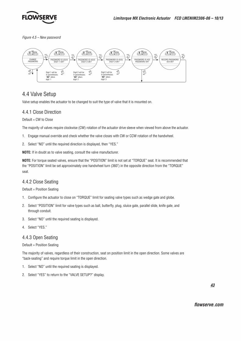
43
Limitorque MX Electronic Actuator FCD LMENIM2306-06 – 10/13
flowserve.com
Figure 4.5 – New password
Digit 1 will be in parentheses; “ NO ” alters digit 1
Digit 2 will be in parentheses; “ NO ” alters digit 2
Digit 3 will be in parentheses; “ NO ” alters digit 3
CHANGE PASSWORD
PASSWORD IS (0)0 0 DIGIT 1-OK?
PASSWORD IS 4(0) 0 DIGIT 2-OK?
PASSWORD IS 42(0) DIGIT 3-OK?
PASSWORD IS 423 PASSWORD OK?
RECORD PASSWORD 423-OK?
NO NO NO NO NO
YES YES YES YES YES YES
4.4 Valve SetupValve setup enables the actuator to be changed to suit the type of valve that it is mounted on.
4.4.1 Close DirectionDefault = CW to Close
The majority of valves require clockwise (CW) rotation of the actuator drive sleeve when viewed from above the actuator.
1. Engage manual override and check whether the valve closes with CW or CCW rotation of the handwheel.
2. Select “NO” until the required direction is displayed, then “YES.”
NOTE: If in doubt as to valve seating, consult the valve manufacturer.
NOTE: For torque seated valves, ensure that the “POSITION” limit is not set at “TORQUE” seat. It is recommended that the “POSITION” limit be set approximately one handwheel turn (360˚) in the opposite direction from the “TORQUE”
seat.
4.4.2 Close SeatingDefault = Position Seating
1. Configure the actuator to close on “TORQUE” limit for seating valve types such as wedge gate and globe.
2. Select “POSITION” limit for valve types such as ball, butterfly, plug, sluice gate, parallel slide, knife gate, and through conduit.
3. Select “NO” until the required seating is displayed.
4. Select “YES.”
4.4.3 Open SeatingDefault = Position Seating
The majority of valves, regardless of their construction, seat on position limit in the open direction. Some valves are “back-seating” and require torque limit in the open direction.
1. Select “NO” until the required seating is displayed.
2. Select “YES” to return to the “VALVE SETUP?” display.

Limitorque MX Electronic Actuator FCD LMENIM2306-06 – 10/13
44
4.5 Torque Switch TimerTorque switch timer permits a user to select a time for the torque switch to time out once the actuator determines that it has reached its torque seat. The torque switch timer can be adjusted from one (1) second to a maximum of fifteen (15) seconds. The default is five (5) seconds.
NOTE: It should be noted that the purpose of this feature is to ensure that the torque sensing has shut off the motor after a brief period of time. It is an additional safety feature to prevent the actuator from reaching a stall torque.
If operating in torque seating for either open or close torque seating, a backup timer can be used to halt the actuator to protect the valve in case the actuator does not torque out after it has passed the expected limit.
1. From “VALVE SETUP?” select “NO” to enter “CHANGE TORQUE TIMER” routine. This option will only appear if either the open or close valve setting is set to torque seating.
2. Select “YES” to change setting. If “NO” is selected, the “POSITION SETUP?” routine will be entered.
4.5.1 StatusDefault = ON
1. Select “NO” to change torque timer status to “OFF”. If “OFF” is selected you will not advance to timer selection for that direction.
4.5.2 Torque TimerThe timer value is how long in seconds that the unit will run once it has passed the expected position limit.
Default = 5 seconds
1. Select “NO” to increase the timer value. The timer is configurable from 1-15 seconds. The counter will wrap around to 1 second when you attempt to increase after 15 seconds.
NOTE: If the unit is only setup for open torque seating, then only the open torque timer will be available to change. This is the same with close torque seating and the close torque timer. If both open and close torque seating are selected then you will be prompted to change close torque timer first, followed by open torque timer.
Figure 4.6 – Torque Switch Timer
YES1
YES5YES2
YES4 YES6 YES8
CHANGE TORQUE SETUP?
CHANGE TORQUE TIMERS?
CLOSE TORQUE TIMER ON/OFF OK?
CLOSE TORQUE TIMER #SEC OK?
OPEN TORQUE TIMER ON/OFF OK?
NO9
NO YES3
NO10
YES
CHANGE VALVE SETUP?
OPEN TORQUE TIMER #SEC OK?
1 - 15 SECDEFAULT 5 SEC
1 - 15 SECDEFAULT 5 SEC
DEFAULT ON
DEFAULT ON
YES YES7
Note 1: YES & CLOSE Torque SeatedNote 2: YES & OPEN Torque Seated CLOSE Position SeatedNote 3: YES & TIMER OFFNote 4: YES & TIMER ONNote 5: YES & TIMER OFF & OPEN Torque Seated
Note 6: YES & OPEN Torque SeatedNote 7: YES & TIMER OFFNote 8: YES & TIMER ONNote 9: NO & Open or Close Torque SeatedNote 10: NO & OPEN/CLOSE Position Seated

45
Limitorque MX Electronic Actuator FCD LMENIM2306-06 – 10/13
flowserve.com
4.6 Torque SetupThe output torque can be changed between 40% and 100% of the rated torque as follows:
1. From “VALVE SETUP?” or “CHANGE TORQUE TIMER?” (if enabled) select “NO” to enter the “TORQUE SETUP?” routine.
2. Select “YES” to change the settings.
If “NO” is selected, the “POSITION SETUP?” routine will be entered.
NOTE: Except for arctic temperature actuators (-30°C or below), which permit torque to be changed from 60%-100%.
4.6.1 Close Torque Valve or Open Torque ValveThe output torque from the actuator to close or open the valve may be configured between 40% and 100% of the rated torque (as stated on the actuator nameplate), in 1% increments (unless limited by the factory).
To Increase the % of Torque Required:1. Select “NO” until the desired % is indicated.
2. Select “YES” to save the required torque.
Should the user select a maximum torque setting less than 100% due to valve or gearbox limitations, this selection can be password protected.
Figure 4.7 – MX Nameplate
Figure 4.8 – Torque setup
YES YES
(40%-100%)
NO
(40%-100%)
YES
NO NO
(Adjustable in 1% increments)
TORQUE SETUP?
CLOSE TORQUE VALUE (100%)-OK?
OPEN TORQUE VALUE (100%)-OK?

Limitorque MX Electronic Actuator FCD LMENIM2306-06 – 10/13
46
4.7 Position SetupChange Settings Menu. After successfully entering the password, answer “NO” to the Change Settings menu prompts until you reach the prompt “CHANGE POSITION SETUP?” Answer “YES.”
4.7.1 Set Position Limits for Electrical Operation1. Set closed valve position. At the “CLOSE VALVE–OK?” prompt, move the red control knob to “LOCAL.” Hold the
black control knob in the “CLOSE” position until the valve has reached the desired position. Move the red control knob to “STOP.”
2. Set the open valve position. At the “OPEN VALVE–OK?” prompt, move the red control knob to “LOCAL.” Hold the black control knob in the “OPEN” position until the valve has reached the desired position. Move the red control knob to “STOP.”
3. Inspect for correct operation. If the position limits are set adjacent to each other then an error message will be displayed: “KEEP OPEN (CLOSE) LIMIT?” The position calibration is now complete. The actuator will function as ordered. Inspect for correct operation by running actuator electrically.
NOTE: For torque seated valves, ensure that the Position limit is not set at torque seat. It is recommended that the Position limit be set approximately one handwheel turn (360˚) in the opposite direction from the torque seat.
a CAUTION: On some valves, position limits could be set adjacent to each other, so be careful that the Close and Open limits are set sufficiently apart to permit operation. If the limits are set adjacent of each other, an error message will be displayed: “KEEP OPEN(CLOSE) LIMIT?”
NO FURTHER MOVEMENT IS PERMITTED UNTIL THE ERROR IS CORRECTED.
Should the User elect to proceed with the setting, an error will be displayed on the screen after re-booting stating “IDENTICAL LIMITS”. THE ACTUATOR WILL NOT MOVE UNTIL THE ERROR IS CORRECTED.
4.7.2 Set Position Limits for Manual Operation1. Set close position. At “SET CLOSE POSITION LIMIT?” answer “YES.” At “CLOSE VALVE-OK?” depress declutch
lever and slowly rotate handwheel until clutch is fully engaged. Release declutch lever; the clutch will stay in hand-wheel mode. If the valve is fully closed, move the handwheel one turn in the open direction to allow for coasting of the motor. When valve is in the desired location, select “YES.” At “SAVE CLOSE LIMIT-OK?” select “YES” to set the close position or “NO” to adjust the setting.
2. Set open position. At “SET OPEN POSITION LIMIT?” select “YES” to get “OPEN VALVE-OK?.” Engage the clutch (see step 1). Valve should be fully opened. Move the handwheel one turn toward the closed position to allow for coasting of the motor. When valve is in the desired location, select “YES” again to set the open position or “NO” to adjust the setting.
3. Checking the settings. Turn the handwheel and verify that the open and close LED’s function correctly (see Checking the Settings). If adjustments are necessary, select “NO” to return to “CHANGE POSITION SETUP?” and repeat from step 1.

47
Limitorque MX Electronic Actuator FCD LMENIM2306-06 – 10/13
flowserve.com
Figure 4.9 – Electrical operation
“NO ” operatesclose direction
“YES” operatesopen direction
Enter “SETUP ” mode
OPEN VALVERETURN TO STOP
OPEN VALVEOK ?
SAVE OPENLIMIT OK?
SETUP?
CLOSE VALVERETURN TO STOP
SAVE CLOSELIMIT OK?
CLOSE VALVEOK ?
CLOSE VALVEOK ?
EXITSETUP?
100% OPENSTATUS OK?
SET CLOSEPOSITION LIMIT?
YES
YES YES2
YES
YES
YES YES YES2
NO NONO NO NO
YES1
NONO
NO
NO
STOP
STOPSTOP
LOCAL
Switch to
LOCAL
Switch to
OPEN VALVEOK ?
SET OPENPOSITION LIMIT?
YES
NONO
SET POSITIONPRECISION?
POSITIONXXX% OPEN?
YES
NONO
POSITIONXXX.X% OPEN?
NO
IDENTICAL LIMITSKEEP OPEN LIMIT?
YES
NO
IDENTICAL LIMITSKEEP CLOSE LIMIT?
YES
NO
YES
YES
YES1
NOTE 1: If open and close limits are not identical
NOTE 2: If open and close limits are identical
Figure 4.10 – Handwheel operation
Declutch actuator; Rotate handwheel to “ CLOS E ” position limit
Rotate handwheel to “ OPEN ” position limit
OPEN VALVE OK ?
SAVE OPEN LIMIT OK?
SAVE CLOS E LIMIT OK?
CLOSE VALVE OK ?
SET CLOS E POSITION LIMIT?
SET OPEN POSITION LIMIT?
YE S STO P YE S YE S
YE S YE S YE S
NO NO NO
NO NO NO
Enter “SETUP ” modeSETUP?
YES
SET POSITIONPRECISION?
POSITIONXXX% OPEN?
YES
NONO
POSITIONXXX.X% OPEN?
NO
YES
YES

Limitorque MX Electronic Actuator FCD LMENIM2306-06 – 10/13
48
4.8 Modutronic OptionThe Modutronic option enables the actuator to be controlled via a milliamp input signal.
• If the Modutronic option has been purchased, it is automatically calibrated when position limits are set. No further adjustments are required, unless the defaults do not suit the application.
• If the Modutronic option has not been purchased, the screens for changing Modutronic will not be available. To add the Modutronic option, please consult Limitorque service at (434) 528-4400.
4.8.1 StatusDefault = OFF
1. Select “NO” to change Modutronic status to “ON.” If “OFF” is selected, no further menus will be displayed.
4.8.2 Proportional BandProportional band is the range of errors between position and demand signal that will produce reduced speed (pulsing).
Default = 15%
To change from the default, select “NO” until the required value is displayed. The value is adjustable between 1% and 100%, in 1% increments.
4.8.3 Fail PositionFail position enables the customer to change the response of the actuator on loss of the milliamp signal.
Default = “CLOSE” Position
Fail position takes effect when the signal level falls below 2 mA or above 20.5 mA.
To Change the Default Position:Select “NO” to choose whether the valve moves to “CLOSE” position, or “OPEN” position, or “STOP” (stops) in its present position at the time of signal failure.
4.8.4 DeadbandDefault = 2%
The deadband should be wide enough to prevent “hunting” of the actuator but as low as possible to give adequate response to changes in the error signal.
To Change from the Default:Select “NO” to adjust the value between 1% and 50%, in 1% increments to suit the application, or 0.5% to 50.0% if the position precision is set to XXX.X%.
4.8.5 Polarity (20 mA)Polarity allows the user to change the valve position corresponding to the maximum milliamp value.
Default Setting is: 20 mA = Full Open
Select “NO” to select the required position of the valve that is to correspond to the maximum signal level of 20 mA.
Choose between: 20 mA = Full Close or Full Open.

49
Limitorque MX Electronic Actuator FCD LMENIM2306-06 – 10/13
flowserve.com
4.8.6 Delay After StopDefault setting = 0 seconds
To change from the default setting, select “NO” to adjust the length of delay time after the actuator stops modulating. The delay after stop is adjustable from 0-60 seconds.
Figure 4.11 – Modutronic option
4.8.7 4-20 mA Signal Range Signal range allows the user to change the signal range from the default range.
Default Setting is for High Reference = 20 mA (High Reference can also be scaled to some older 10-50mA instrumenta-tion systems. A 166.66 Ohm resistor should be placed across the milliamp inputs when scaled from 10-50 mA.)
Default Setting for Low Reference = 4 mA
To change signal range (i.e. 4 mA-12 mA or 12 mA-20 mA or others) answer “YES.” Proceed from “SET HIGH REFERENCE” to “SET HIGH REFERENCE - OK?” A “YES” answer will require the use of a calibrator. If no, change to the signal range is required, answer “NO” and return to “CHANGE MODUTRONIC?” dialog.
4.8.8 Set High ReferenceDefault = 20 mA
1. Select “NO” to accept pre-existing setting (no change).
2. Select “YES” to enter the display “APPLY HIGH LEVEL CONTROL SIGNAL.”
3. Apply this signal to terminal 19 and 20 indicated on the wiring diagram.
4. Select “YES” again to record this signal as the high reference. See Figure 4.10.
4.8.9 Set Low ReferenceDefault = 4 mA
1. Select “NO” to move from “SET HIGH REFERENCE” to “SET LOW REFERENCE.”
2. Select “YES” to enter the display “APPLY LOW LEVEL CONTROL SIGNAL.”
3. Using a calibrator, apply the low signal, and select “YES” to record this signal as the low reference.
YES YES
(OFF) (ON)
YES YES YES
(1%-100%) 1% increments
(0.1%-100%)0.1% increments*
* Only if SET POSITION PRECISION is set for XXX.X% OPEN
(0.1%-50%)0.1% increments*
(OPEN ) (STOP)
(1%-50%) 1% increments
YES YES
NO NO NO NO NO NO NO NO NO
NO
YES
CHANGE MODUTRONIC?
STATUS (ON)-OK?
PROP BAND (15%)-OK?
FAIL POSITION (CLOSE)-OK?
DEADBAND (2%)-OK?
POLARITY 20 m A=OPEN-OK?
D ELAY AFTER STO P 0 SECONDS-OK?
4-20 mA SIGNAL RANGE?
SET LO W REFERENCE-OK?
SET HIGH REFERENCE-OK?
POLARITY 20 mA-CLOSE-OK?
D ELAY AFTER STO P 60 SECONDS-OK?

Limitorque MX Electronic Actuator FCD LMENIM2306-06 – 10/13
50
Figure 4.12 – Modutronic signals
NO
YES YES
To “ SET LOW
REFERENCE ”
YES
YES YES
“ CHANGE MODUTRONIC”
YES
NO
NO
Flow to “ CHANGE MODUTRONIC ”
NO
NO
NO
SET HIGH REFERENCE-OK?
A PPLY HIGH LEVEL C ONTROL SIGNA L
HIGH REFERENCE (OK)-EXIT
SET LO W REFERENCE-OK?
APPLY L OW LEVEL C ONTROL SIGNA L
LOW REFERENCE (OK)-EXIT
4.8.10 Modutronic LCD DisplayWhen the Modutronic option has been purchased, is set to “ON,” and the red selector switch is in “REMOTE,” the normal LCD display will read:
XXX% OPEN XXX% DEMAND XXX.X% OPEN
XXX.X% DEMAND
*
* If SET POSITION PRECISION is set to XXX.X% OPEN
XXX% Demand is the percentage value of the milliamp input signal.
4.9 DDC/Modbus OptionDDC option enables the actuator to be controlled by an RS-485 serial communication signal. If the DDC option has been purchased, it is automatically enabled. The customer must set the DDC address.
NOTE: If the DDC option has not been purchased, the screens for changing DDC will not be available. To add the DDC option, please consult Limitorque service at (434) 528-4400.
The MX is equipped with the ability to either hardwire to digital inputs for control, set-up for analog control (Modutronic), or control via network protocols. In order to utilize this feature, then select “Multi-control mode” operation located in Section 4.16, Remote Mode. This is the default setting for remote control. There are three modes of remote control when remote mode is configured for multi control: digital control, analog control, and network control. Digital and network control operation is based on the last command received. Analog operation is initiated by either toggling user input 2 (configure for CSE input) or breaking and reapplying the analog control.
4.9.1 StatusDefault = ON
DDC Status enables user to change from the default condition to turn on and off the digital control capability of the actuator.
To Change from the Default Setting:Select “NO” to switch DDC to “OFF.” If “OFF” is selected, no further menus will be displayed.

51
Limitorque MX Electronic Actuator FCD LMENIM2306-06 – 10/13
flowserve.com
4.9.2 Network AddressDefault = 1
Network address allows user to assign a unique network address to an actuator.
1. The network address must be entered in accordance with the Instrument Data Sheet, and care must be taken to ensure that the same address is not used anywhere else in the same network.
2. Select “NO” for small incremental changes or hold it continuously in that position for larger changes until the required value is displayed. The address may be set at any value between 001 and 250.
4.9.3 ProtocolDefault = Modbus RTU 9600 Baud
Protocol changes the communication language/speed from the default to match the application.
To Change from the Default Language:Select “NO” to choose between MODBUS, ASCII, or RTU, and the baud rate depending on the design of the DDC system. Refer to the contract documentation.
4.9.4 Analog ScaleDefault = 0-100
Analog scale allows the user to change the scaling of the analog input from the default.
To Change from the Default Range:Select “NO” until the required scale is displayed. 0-255 and 0-4095 counts are available.
4.9.5 ESD ActionA network ESD function can be enabled after the ESD configuration has been established for the unit. This network ESD can be selected to either ignore the command; Close, Open, Stop, or Position the actuator.
Figure 4.13 – DDC
YES
NO
CHANGEDDC?
(ON)
YES
NO
STATUS(OFF)-OK?
(CLOSE)(OPEN)(STOP)
(POSITION)
YES
NO
ESD ACTION(IGNORE)-OK?
(CLOSE)(OPEN)(STOP)
(POSITION)
YES
NO
COMM LOSS ACTION(NONE)-OK?
(0-4095)
YES
NO
COMM LOSS DELAY(60 SEC)-OK?
(ASCII)
YES
NO
MODBUSRTU-OK?
(0-100%)
* *YES
NO
MOVE TOXXX% OPEN
(0-100%)
YES
NO
MOVE TOXXX% OPEN
(2400-19.2K)
YES
NO
BAUD RATE9600-OK?
(1-250)
YES
NO
DDC ADDRESS1-OK?
(0-255)(0-4095)
YES
NO
ANALOG SCALE(0-100)-OK
YES
NO
CHANGE PROPDEAD BAND?
(1-100%)
YES
NO
PROP BAND(8%)-OK?
(1-?%)
YES
NO
DEADBAND(2%)
* If POSITION is chosen, as action, this menu will appear.
NOTE: These settings are the same for multi-drop standard DDC on main board and DDC network board. If customer has both, then they will have the same settings.

Limitorque MX Electronic Actuator FCD LMENIM2306-06 – 10/13
52
4.9.6 Proportional BandProportional band is the range of errors between position and demand signal that will produce reduced speed (pulsing).
Default = 15%
To change from the default, select “NO” until the required value is displayed. The value is adjustable between 1% and 100%, in 1% increments.
4.9.7 DeadbandDefault = 2%
The deadband should be wide enough to prevent “hunting” of the actuator but as low as possible to give adequate response to changes in the error signal.
To Change from the Default Range:Select “NO” to adjust the value between 0.5% and 50%, in 0.5% increments to suit the application.
4.9.8 OffsetDefault = 4 mA/20 mA
No options are available. Select “YES.”
0-10 VDC is available on all units shipped after 6/01/03.
4.9.9 Move ToIf positioning is selected as an action, then the Move To dialog will appear. Position is configurable from 0-100%.
4.9.10 Comm Loss DelayDefault = 60 sec.
The User may select the amount of time delay before communication loss is flagged to the network. This selection is configurable from 120 seconds.
4.9.11 Comm Loss Action Default = None
The User may select what action the actuator should take when network communication is interrupted. This action is configurable as Close, Open, Stop, Position.
4.10 FF OptionFF option enables the actuator to be controlled by a Foundation Fieldbus communications signal. If the option has been purchased, it is automatically enabled. A Fieldbus System configuration tool must be used by the customer to set the FF address.
NOTE: If the FF option has not been purchased, the screens for changing FF will not be available. To add the FF option, please consult Limitorque service at (434) 528-4400.
The MX is equipped with the ability to either hardwire to digital inputs for control, set-up for analog control (Modutronic), or control via network protocols. In order to utilize this feature, then select “Multi-control mode” operation located in Section 4.16, Remote Mode. This is the default setting for remote control. There are three modes of remote control when remote mode is configured for multi control: digital control, analog control, and network control. Digital and network control operation is based on the last command received. Analog operation is initiated by either toggling user input 2 (configure for CSE input) or breaking and reapplying the analog control.

53
Limitorque MX Electronic Actuator FCD LMENIM2306-06 – 10/13
flowserve.com
4.10.1 StatusDefault = ON
FF Status enables user to change from the default condition to turn on and off the digital control capability of the actuator.
4.10.2 Terminate BusShould a user select to make this unique actuator the termination point for the network, select “YES.” If not, then “NO.” Default is “NO.”
4.10.3 Analog ScaleDefault = 0-100
Analog scale allows the user to change the scaling of the analog input from the default.
To Change from the Default Range:Select “NO” until the required scale is displayed. 0-255 and 0-4095 counts are available.
4.10.4 ESD ActionA network ESD function can be enabled after the ESD configuration has been established for the unit. This network ESD can be selected to either ignore the command; Close, Open, Stop, or Position the actuator.
4.10.5 OPEN/CLOSE ModeDefault = YES
To select operation as typically ”OPEN” or “CLOSE,” select “YES.” To select operation as position mode, select “NO.”
4.10.6 Proportional BandProportional band is the range of errors between position and demand signal that will product reduced speed (pulsing).
Default = 15%
To change from default, select “NO” until the required value is displayed. The value is adjustable between 1% and 100%, in 1% increments.
4.10.7 DeadbandDefault = 2%
The deadband should be wide enough to prevent “hunting” of the actuator but as low as possible to give adequate response to changes in the error signal.
To change from default, select “NO” to adjust the value between 1% and 50%, in 1% increments to suit the application.

Limitorque MX Electronic Actuator FCD LMENIM2306-06 – 10/13
54
Figure 4.14 – FF
4.10.8 Comm Loss DelayDefault = 60 sec.
The User may select the amount of time delay before communication loss is flagged to the network. This selection is configurable from 120 seconds.
4.10.9 Comm Loss Action Default = None
The User may select what action the actuator should take when network communication is interrupted. This action is configurable as Close, Open, Stop, Position.
4.11 PB OptionPB option enables the actuator to be controlled by a Profibus communications signal. If the option has been purchased, it is automatically enabled. A Fieldbus System configuration tool must be used by the customer to set the PB address.
NOTE: If the PB option has not been purchased, the screens for changing PB will not be available. To add the PB option, please consult Limitorque service at (434) 528-4400.
MX Multi-control Mode Operation - The MX is equipped with the ability to either hardwire to digital inputs for control, set-up for analog control (Modutronic), or control via network protocols. In order to utilize this feature, then select “Multi-control mode” operation located in Section 4.16, Remote Mode. This is the default setting for remote control. There are three modes of remote control when remote mode is configured for multi control: digital control, analog control, and network control. Digital and network control operation is based on the last command received. Analog operation is initiated by either toggling user input 2 (configure for CSE input) or breaking and reapplying the analog control.
NO (OFF)
YES
NO NO
NO
YES
YESYES YES
(1%-100%)1% Increments
(1%-50%)1% Increments
CHANGE FF?
STATUS (ON)-OK?
YES
CHANGE PROP/DEADBAND?
NO
YES
DEADBAND(2%)-OK?
PROP BAND(15%)-OK?
NO
OPEN/CLOSEMODE-OK?
POSITIONMODE-OK?
(CLOSE)(OPEN)(STOP)
(POSITION)
YES
NO
ESD ACTION(IGNORE)-OK?
(CLOSE)(OPEN)(STOP)
(POSITION)
YES YES
NO
COMM LOSS ACTION(NONE)-OK?
(0-4095)NO
COMM LOSS DELAY(60 SEC)-OK?
(0-100%)
** YES
NO
MOVE TOXXX% OPEN
(0-100%)
YES
NO
MOVE TOXXX% OPEN
* If POSITION is chosen, as action, this menu will appear.
NO(0-255)(0-4095)
YES
ANALOG SCALE0-100-OK?

55
Limitorque MX Electronic Actuator FCD LMENIM2306-06 – 10/13
flowserve.com
Figure 4.15 – Profibus DP
4.11.1 StatusDefault = ON
PB Status enables user to change from the default condition to turn on and off the digital control capability of the actuator.
4.11.2 PB DP OperationFigure 4.15 illustrates the setup sequence for the MX/QX PB DP field unit. For proper operation, either Position Mode or Open/Close Mode must be selected.
Follow these steps to enter and configure the setup mode:
1. Proceed through the Setup to the CHANGE PBDP? display.
2. Select YES to proceed to the PBDP-A STATUS (ON)-OK? display. PBDP-A Status enables the user to change from the default condition to turn on and off the digital control capability of the actuator.
3. Select YES to proceed to the PBDP-B STATUS (ON)-OK? display. PBDP-B Status enables the user to change from the default condition to turn on and off the redundant digital control capability of the actuator, if installed.
4. Select YES to proceed to the REDUNDANT MASTER (YES)-OK? display. Selecting REDUNDANT MASTER will allow for System Redundancy with two independent connections to Profibus masters. REDUNDANT MASTER must be set to NO for Flying Redundancy (single Profibus master connection).
5. If YES is selected, MONITOR STANDBY PB (ON)-OK? is displayed.
6. To allow the standby Profibus master to monitor the health of the actuator’s standby PB DP board, select YES.
7. The unit will display PB ADDRESS 1–OK? If OK, select YES. If NO, select different address (1-125).
8. Select YES to proceed to the ANALOG SCALE display.
9. From ANALOG SCALE, if the default value of 0-100 is OK, select YES. If not, select NO.
10. If YES is selected, ESD ACTION (IGNORE) – OK? is displayed.
11. For ignoring ESD ACTION, select YES. For setting ESD ACTION, select NO. If POSITION is chosen as action, ESD MOVE TO (XXX%)-OK? is displayed. Select NO to set desired position.
*
YES
NO
CHANGE PB/DP?
YES
NO
PBDP-A STATUS (ON)-OK?
YES
NO
PBDP-B STATUS (ON)-OK?
YES
NO
MONITOR STANDBY PB (ON)-OK?
YES
NO(0-125)Unit increments
PB ADRESS1 OK?
YES
NO(0-255)(0-4095)
ANALOG SCALE 0-100-OK?
YES
NO
REDUNDANT MASTER (YES)-OK?
YES
NO(CLOSE)(OPEN)(STOP)
(POSITION)
COMMLOSS ACTION (NONE)-OK?
YES
NO(0-100%)
ESD MOVE TO (XXX%)-OK?
YES
NO(0-4095)
COMMLOSS DELAY 60 SECS-OK?
YES
NO(CLOSE)(OPEN)(STOP)
(POSITION)
ESD ACTION (IGNORE)-OK?
* YES
NO(0-100%)
MOVE TO (XXX%)-OK?
YES
NO
OPEN/CLOSE MODE-OK?
YES
POSITION MODE-OK?
YES
NO
CHANGE PROP/ DEAD BAND?
YES
NO(1%-100%)1% Increments
PROP BAND (15%)-OK?
YES
NO(1%-50%)1% Increments
DEADBAND (2%)-OK?
* If POSITION is chosen, as action, this menu will appear.

Limitorque MX Electronic Actuator FCD LMENIM2306-06 – 10/13
56
12. If YES is selected, COMM LOSS ACTION (NONE) – OK? is displayed.
13. For no COMM LOSS ACTION, select YES. For setting COMM LOSS ACTION, select NO. If POSITION is chosen, as action, COMM LOSS MOVE TO (XXX%)-OK? is displayed. Select NO to set desired position.
14. If YES is selected, COMM LOSS DELAY (60 SEC) – OK? is displayed.
15. For a 60-second delay, select YES. Otherwise, select NO until the required value is displayed.
16. If YES is selected, OPEN/CLOSE MODE-OK? is displayed.
17. For OPEN/CLOSE MODE, select YES. For POSITION MODE, select NO. In position mode, the host device can set the valve position to any desired value; in OPEN/CLOSE MODE the host can only fully open or fully close the valve. The user must locally configure one of these two modes.
18. Proceed to configure the proportional band and deadband as discussed in the next sections.
4.11.3 Comm Loss DelayDefault = 60 sec.
The User may select the amount of time delay before communication loss is flagged to the network. This selection is configurable from 120 seconds.
4.11.4 Comm Loss Action Default = None
The User may select what action the actuator should take when network communication is interrupted. This action is configurable as Close, Open, Stop, Position.
Figure 4.16 – Profibus PA
NO(OFF)
YES
NO NO
NO
YES
YESYES YES
(1%-100%)1% Increments
(1%-50%)1% Increments
CHANGE PB/PA?
STATUS(ON)-OK?
YES
CHANGE PROP/DEADBAND?
NO
YES
DEADBAND(2%)-OK?
PROP BAND(15%)-OK?
NO
OPEN/CLOSEMODE-OK?
POSITIONMODE-OK?
NO
YES
NO
YES
PB ADDRESS(1)-OK?
(1-125)Unit Increments
(CLOSE)(OPEN)(STOP)
(POSITION)
YES
NO
ESD ACTION(IGNORE)-OK?
(CLOSE)(OPEN)(STOP)
(POSITION)
YES YES
NO
COMM LOSS ACTION(NONE)-OK?
(0-4095)NO
COMM LOSS DELAY(60 SEC)-OK?
(0-100%)
** YES
NO
MOVE TOXXX% OPEN
(0-100%)
YES
NO
MOVE TOXXX% OPEN
* If POSITION is chosen, as action, this menu will appear.
ANALOG SCALE0-100-OK?

57
Limitorque MX Electronic Actuator FCD LMENIM2306-06 – 10/13
flowserve.com
4.12 DN OptionDN option enables the actuator to be controlled by a DeviceNet communications signal. If the option has been purchased, it is automatically enabled. A DeviceNet System configuration tool must be used by the customer to set the DN address.
NOTE: If the DN option has not been purchased, the screens for changing DN will not be available. To add the DN option, please consult Limitorque service at (434) 528-4400.
The MX is equipped with the ability to either hardwire to digital inputs for control, set-up for analog control (Modutronic), or control via network protocols. In order to utilize this feature, then select “Multi-control mode” operation located in Section 4.16, Remote Mode. This is the default setting for remote control. There are three modes of remote control when remote mode is configured for multi control: digital control, analog control, and network control. Digital and network control operation is based on the last command received. Analog operation is initiated by either toggling user input 2 (configure for CSE input) or breaking and reapplying the analog control.
4.12.1 StatusDefault = ON
DN Status enables user to change from the default condition to turn on and off the digital control capability of the actuator.
4.12.2 Baud RateDefault = 125K Baud
Baud rate changes the communication speed from the default to match the application.
To Change from the Default Speed:Select “NO” to choose between 125k, 250k, 500k baud rate depending on the design of the DN system. Refer to the contract documentation.
4.12.3 Network AddressDefault = 1
Network address allows user to assign a unique network address to an actuator.
1. The network address must be entered in accordance with the Instrument Data Sheet, and care must be taken to ensure that the same address is not used anywhere else in the same network.
2. Select “NO” for small incremental changes or hold it continuously in that position for larger changes until the required value is displayed. The address may be set at any value between 001 and 63.
4.12.4 Analog ScaleDefault = 0-100
Analog scale allows the user to change the scaling of the analog input from the default.
To Change from the Default Range:Select “NO” until the required scale is displayed. 0-255 and 0-4095 counts are available.
4.12.5 ESD ActionA network ESD function can be enabled after the ESD configuration has been established for the unit. This network ESD can be selected to either “IGNORE” the network command; or Close, Open, Stop, Position the actuator.

Limitorque MX Electronic Actuator FCD LMENIM2306-06 – 10/13
58
4.12.6 Proportional BandProportional band is the range of errors between position and demand signal that will produce reduced speed (pulsing).
Default = 15%
To change from the default, select “NO” until the required value is displayed. The value is adjustable between 1% and 100%, in 1% increments.
4.12.7 DeadbandDefault = 2%
The deadband should be wide enough to prevent “hunting” of the actuator but as low as possible to give adequate response to changes in the error signal.
To Change from the Default Range:Select “NO” to adjust the value between 1% and 50%, in 1% increments to suit the application.
Figure 4.17 – DN option
DNET ADDRESSNET CTRL-OK?
ANALOG SCALE(0-100)-OK
* If POSITION is chosen, as action, this menu will appear.
YES
NO(ON)
YES
NO
(CLOSE)(OPEN)(STOP)
(POSITION)
YES
NO
ESD ACTION(IGNORE)-OK?
(CLOSE)(OPEN)(STOP)
(POSITION)
YES
NO
COMM LOSS ACTION(NONE)-OK?
(0-4095)
YES
NO
(ASCII)
YES
NO
(0-100%)
* *YES
NO
MOVE TOXXX% OPEN
(0-100%)
YES
NO
MOVE TOXXX% OPEN
(2400-115.2K)
YES
NO(1-250)
YES
NO
YES
NO
CHANGE PROPDEAD BAND?
(1-100%)
YES
NO
PROP BAND(8%)-OK?
(1-?%)
YES
NO
DEADBAND(2%)
CHANGEDEVICENET?
STATUS(OFF)-OK?
BAUD RATEAUTO-OK?
COMM LOSS DELAY(60 SEC)-OK?
4.12.8 Comm Loss DelayDefault = 60 sec.
The User may select the amount of time delay before communication loss is flagged to the network. This selection is configurable from 120 seconds.
4.12.9 Comm Loss Action Default = None
The User may select what action the actuator should take when network communication is interrupted. This action is configurable as Close, Open, Stop, Position.

59
Limitorque MX Electronic Actuator FCD LMENIM2306-06 – 10/13
flowserve.com
4.12.6 Proportional BandProportional band is the range of errors between position and demand signal that will produce reduced speed (pulsing).
Default = 15%
To change from the default, select “NO” until the required value is displayed. The value is adjustable between 1% and 100%, in 1% increments.
4.12.7 DeadbandDefault = 2%
The deadband should be wide enough to prevent “hunting” of the actuator but as low as possible to give adequate response to changes in the error signal.
To Change from the Default Range:Select “NO” to adjust the value between 1% and 50%, in 1% increments to suit the application.
Figure 4.17 – DN option
DNET ADDRESSNET CTRL-OK?
ANALOG SCALE(0-100)-OK
* If POSITION is chosen, as action, this menu will appear.
YES
NO(ON)
YES
NO
(CLOSE)(OPEN)(STOP)
(POSITION)
YES
NO
ESD ACTION(IGNORE)-OK?
(CLOSE)(OPEN)(STOP)
(POSITION)
YES
NO
COMM LOSS ACTION(NONE)-OK?
(0-4095)
YES
NO
(ASCII)
YES
NO
(0-100%)
* *YES
NO
MOVE TOXXX% OPEN
(0-100%)
YES
NO
MOVE TOXXX% OPEN
(2400-115.2K)
YES
NO(1-250)
YES
NO
YES
NO
CHANGE PROPDEAD BAND?
(1-100%)
YES
NO
PROP BAND(8%)-OK?
(1-?%)
YES
NO
DEADBAND(2%)
CHANGEDEVICENET?
STATUS(OFF)-OK?
BAUD RATEAUTO-OK?
COMM LOSS DELAY(60 SEC)-OK?
4.12.8 Comm Loss DelayDefault = 60 sec.
The User may select the amount of time delay before communication loss is flagged to the network. This selection is configurable from 120 seconds.
4.12.9 Comm Loss Action Default = None
The User may select what action the actuator should take when network communication is interrupted. This action is configurable as Close, Open, Stop, Position.
4.13 HART OptionHART option enables the actuator to be controlled by a Highway Addressable Remote Transducer communications signal. If the option is purchased, it is automatically enabled. The device address is fixed for point-to-point connection, but must be set by customer for multi-drop topology.
NOTE: If the HART option has not been purchased, the screens for changing HART will not be available. To add the HART option, please consult Limitorque service at (434) 528-4400.
The MX is equipped with the ability to either hardwire to digital inputs for control, set-up for analog control (Modutronic), or control via network protocols. In order to utilize this feature, select “Multi-control mode” operation located in Section 4.16, Remote Mode. This is the default setting for remote control. There are three modes of remote control when remote mode is configured for multi-control: digital control, analog control, and network control. Digital and network control operation is based on the last command received. Analog operation is initiated be either toggling user input 2 (configure for CSE input) or breaking and reapplying the analog control signal.
Figure 4.18 – HART
4.13.1 StatusDefault = ON
HART Status enables user to change from the default condition to turn on and off the digital control capability of the actuator.
4.13.2 Multi-dropDefault = Disabled
MULTI-DROP (ENABLED) or (DISABLED) allows the user to select the desired network topology. To change the setting, select NO until the required option is displayed. Select YES if the setting is correct to go to the next display.
NOTE: Changing the topology also requires that the network be wired correctly for the selected topology.
CHANGEHART?
ESD ACTION(IGNORE)-OK?
CHANGECLOCK?
CLOCK(DISABLED)-OK?
YEAR2012
MONTH1
DAY1
CHANGEHART?
MINUTE0
SECOND0
SAVECLOCK?
MOVE TOXXX% OPEN
(OFF)-OK?
STATUS(ON)-OK?
(ENABLED)-OK?
MULTI-DROP(DISABLED)-OK?
FAIL POSITION(CLOSE)-OK?
MOVE TOXXX% OPEN?
POLLING ADDRESS(O)-OK?
SAVESETTINGS-OK?
CHANGE PROP/DEADBAND?
PROP BAND(5%)-OK?
DEADBAND(2%)-OK?
(POSITION SETPOINT)-OK?
(OPEN)-OK?(STOP)-OK?
(POSITION)-OK?
Input no matter ifDigital or Analog
If Hart Actuatorand Multidrop
If fall position isnot “position”
If fail position is“position”
(ENABLED)-OK?
Address default is zeroRange is 0-63If Hart Actuctor
and not Multidrop
INPUT ACTION(USER INPUT)-OK?
YES
NO
(CLOSE)-OK?(STOP)-OK?(OPEN)-OK?
(POSITION)-OK?

Limitorque MX Electronic Actuator FCD LMENIM2306-06 – 10/13
60
4.13.3 Input ActionDefault = User Input
INPUT ACTION allows the user to set the input action as USER INPUT or POSITION SETPOINT.
NOTE: If MULTI-DROP ENABLED was chosen, skip to POLLING ADDRESS. Otherwise, FAIL POSITION display is shown. In multi-drop mode the input is digital only (write PV over network), so there is no analog fail action.
4.13.4 Fail PositionDefault = Close
FAIL POSITION allows the user to configure the action desired upon loss of the analog input signal. The selections are CLOSE, OPEN, STOP, and POSITION. Select the desired setting and proceed to the next display.
NOTE: If POSITION is chosen as the action, a MOVE TO display will be shown where the user can select the desired position between 0 and 100% open, in one percent increments, by selecting NO until the desired position is selected. Select YES once the setting is correct to go to the next display.
4.13.5 Polling AddressDefault = 0
POLLING ADDRESS allows the user to set the HART polling address of the unit. Point-to-Point units are typically set to address 0, and Multi-drop units are typically set from 1-63. HART 5 masters will always set Point-to-Point units to address 0.
4.13.6 Save SettingsSAVE SETTINGS allows the user to save the settings and make them active. This can result in a change in the hardware configuration on the HART board to support the change in configuration. Select NO to return to STATUS and change settings. Select YES to save the HART configuration settings and go to additional network settings.
NOTE: The configuration set in steps 1-6 will not be saved if the user does not select YES for SAVE SETTINGS.
4.13.7 Change Prop / DeadbandCHANGE PROP / DEADBAND allows for the setting of proportional band and deadband. Proportional band is the range of errors between the position and demand signal that will produce reduced speed (pulsing). The default value is 5%. To change from default, select NO until the required value is displayed. The value is adjustable between 1% and 100%, in 1% increments. The default deadband value is 2%. For error signals less than this, no motion occurs. The deadband should be wide enough to prevent “hunting” of the actuator but as low as possible to give adequate response to changes in the error signal. To change from the default, select NO to adjust the value between 1% and 50%, in 1% increments to suit the application.
4.13.8 ESD ActionDefault = None
ESD ACTION allows a network ESD function to be enabled after the ESD configuration has been established for the unit. This network ESD can be selected to do one of the following: ignore the command (NONE), CLOSE, OPEN, STOP, or POSITION the actuator. To change from the default setting, select NO until the required option is displayed. Select YES if the setting is correct to go to the next display.
NOTE: If POSITION is chosen as the action, a MOVE TO display will be shown where the user can select the desired posi-tion between 0 and 100% open, in one percent increments, by selecting NO until the desired position is selected. Select YES once the setting is correct to go to the next display.

61
Limitorque MX Electronic Actuator FCD LMENIM2306-06 – 10/13
flowserve.com
4.13.9 Change ClockCHANGE CLOCK allows the user to select the real time clock settings. Select NO if you do not wish to set the clock and the menus will return to CHANGE HART. Select YES to enable clock and set YEAR, MONTH, DAY, HOUR, MINUTE, and SECOND values. SAVE CLOCK allows the clock settings to be saved. The clock is non-volatile if power is lost or the unit is reset, the clock must be set again. If the clock is enabled, the LCD will display “SET CLOCK” after a power cycle/reset. If the clock is not enabled, the LCD will not display “SET CLOCK”. The clock may also be set and read from the network via HART commands 89 and 90. If the clock is not set, the HART board will keep a running counter in place of the clock.
4.14 Status and Alarm ContactsThe status and alarm contacts permit wiring to existing contacts for visibility of operation or fault conditions. (See wiring diagram for contact ratings.)
The status contacts (S) and optional alarm contacts (R) may be configured to have any one of the following functions:
• “CLOSING” – valve closing • “OPENING” – valve opening• “STOPPED” – valve stopped in mid-travel • “VALVE MOVING” – either direction• “LOCAL SELECTED” – red selector knob in “LOCAL”• “MOTOR OVERTEMP” – thermistor range exceeded• “OVERTORQUE” – torque exceeded in mid-travel• “MANUAL OVERRIDE” – actuator moved by handwheel• “VALVE JAMMED” – valve can’t move• “CLOSE TORQUE SW” – torque switch trip at “CLOSED”• “OPEN TORQUE SW” – torque switch trip at “OPEN”• “LOCAL STOP/OFF” – red selector knob at “STOP Selected”• “LOST PHASE” – one or more of three phases lost• “ESD SIGNAL” – signal active • “CLOSE INHIBIT” – close inhibit signal active• “OPEN INHIBIT” – open inhibit signal active• “ANALOG IP LOST” – 4-20 mA not present• “REMOTE SELECTED” – red selector in “REMOTE”• “LIMIGARD ACTIVE” – (future—LimiGard™ functionality is not affected)• “HARDWARE FAILURE” – indication• “NETWORK CONTROLLED” – permits relay control via DDC, FF, or other network driver• “CLOSE” – valve closed “(0% OPEN)”• “OPEN” – valve open “(100% OPEN)”• “MID-TRAVEL” – valve position, 1-99% open• “CSE CONTROL” – CSE station in LOCAL or STOP and controls actuator• “PS ACTIVE”, “PS PASSED”, “PS FAILED TARGET”, “PS FAILED RETURN”• “PS” – Partial Stroke, activated if PS is configured
4.14.1 Status and Alarm Contact Default SettingsAll actuators are supplied with the following status or alarm (optional) contact default factory settings:
Status ContactsS1a – Normally closed contact at valve fully Close
S1b – Normally closed contact at valve fully Open

Limitorque MX Electronic Actuator FCD LMENIM2306-06 – 10/13
62
S2a – Normally open contact at valve fully Close
S2b – Normally open contact at valve fully Open
Alarm Contacts (Optional/requires I/O board)R1 – Normally closed contact at valve fully Close R5 – Motor Overtemp
R2 – Normally closed contact at valve fully Open R6 – Remote Selected
R3 – Normally open contact at valve fully Close R7 – Overtorque
R4 – Normally open contact at valve fully Open R8 – Analog I/P (Input)
To change any of the default settings: Select “CHANGE STATUS & ALARM CONTACTS?” from the “SETUP” routine.
Select “YES” to enter the “SETUP” routine for each individual contact. Select “NO” until the particular contact is referenced in the display, then “YES” to make the changes.
4.14.2 Status FunctionToggle “NO” through the range of functions, as listed, until the desired feature is displayed.
Figure 4.19 – Status and alarm contacts (Shown with optional boards added)
NO
YES
NO
NO
NO
NO
NO
YES YES
NO
YES YES YES
YES
(CLOSE) (BLINKER)
Same as changing status contact S1
Same as changingalarm contact R1
NO
(Option)
CHANGE STATUS & ALARM CONTACTS?
CHANGE STATUS CONTACT S1a?
CHANGE ALARMCONTACT R1?
STATUS FUNCTION CLOSE?
CONTACT (OPEN)-OK?
STATUS FUNCTION(LOCAL SELECTED)?
CONTACT(CLOSE)-OK?
CONTACT S1b?
CONTACT S2a?
CONTACT S2b?
CONTACT R2?
CONTACT R3?
CONTACT R4?
CONTACT R5?
CONTACT R6?
CONTACT R7?
CONTACT R8?
Note: S1b, S2b are not configurable. They will change states from S1a, S2a. For example, if S1a is configured for normally closed, then S1b will be normally open.
NO (DISABLE)
YES
ENABLE ALARMCONTACT R1?
Status functions:1. CLOSING2. OPENING3. STOPPED4. VALVE MOVING5. LOCAL SELECTED6. MOTOR OVERTEMP7. OVERTORQUE8. MANUAL OVERRIDE9. VALVE JAMMED10. CLOSE TSW11. OPEN TSW12. LOCAL STOP/OFF13. LOST PHASE14. ESD SIGNAL15. CLOSE INHIBIT
16. OPEN INHIBIT17. ANALOG I/P LOST18. REMOTE SELECTED19. LIMIGARD ACTIVE20. HARDWARE FAILURE21. NETWORK CONTROLLED22. CLOSE23. OPEN24. MID-TRAVEL25. CSE CONTROL26. PS ACTIVE27. PS PASSED28. PS FAILED TARGET29. PS FAILED RETURN
4.14.3 ContactThis mode allows the user to select the state of the contact when the function is active. Select “NO” to choose whether the contact is required to be normally closed, normally open, or blinker when the function is active. When “Blinker” has been selected, the contact will switch automatically between open and close (1 second open/1 second close).

63
Limitorque MX Electronic Actuator FCD LMENIM2306-06 – 10/13
flowserve.com
4.14.4 Valve PositionThis display will appear only if the function “MID-TRAVEL POSITION” has been selected. Toggle “NO” until the display indicates the required value of percentage “OPEN” at which the contact should trip. If the contact has been selected as normally closed, then it will close when the trip point has been reached, with the actuator moving in the open direction.
NOTE: Status contacts (S) and optional alarm (R) contacts are latching type and will remain in their last set position in the event of a main power supply failure.
4.15 Two-speed Timer (Optional)The optional two-speed timer extends the operating time of the actuator, in the closing and/or the opening direction, by pulsing the motor ON and OFF. Pulsing may be applied to full valve travel or only a part of it. The ON and OFF pulse times are adjustable.
1. Select “CHANGE 2-SPEED TIMERS?”
2. Select “YES” to enter the “CHANGE OPEN TIMER?” routine.
3. If slow opening is required, select “YES;” otherwise select “NO” to move into the “CHANGE CLOSE TIMER?” routine.
4.15.1 Status
Select “NO” to switch the timer ON or OFF. If OFF, no further menus will be displayed.
4.15.2 Start PositionIf the Close or Open timer has been switched ON, pulsing will start when the set point is reached in the selected direc-tion and the actuator will continue pulsing until the valve reaches the desired “STOP” position.
Select “NO” until the display indicates the required value of percentage OPEN at which the pulsing should start. Adjustable in 1% increments as listed:
Closing = 0% to 99%. Opening = 1% to 100%.
4.15.3 Stop PositionIf the Close or Open timer has been switched ON, pulsing will commence as the valve moves out of its close position and the actuator will continue pulsing until stopped at the set point.
Select “NO” until the display indicates the required value of percentage open at which the pulsing should stop. Adjustable in 1% increments as listed:
Closing = 0% to 99%. Opening = 1% to 100%.
4.15.4 Pulse Time – ONThis mode allows user to change the ON pulse time from the default setting.
Default Setting = 2.0 Second
Select “NO” until the required length of ON pulse is displayed. Adjustable between 1 and 20 seconds, in 0.5 second increments.

Limitorque MX Electronic Actuator FCD LMENIM2306-06 – 10/13
64
Figure 4.20 – Two-speed timers
NO
YES YES YES YES YES YES
NO NO
YES YES YES YES YES
NO
YES
NO NO NO NO (0% - 99%) (Start +1% - 99% )
(OFF)
(OFF) (1% - 100%) 1% increments
(1% - 100% ) 1% increments
(1-20 sec) 0.5 sec
increments
(1-200 sec) 1.0 sec
increments
YES
NO NO NO NO NO
(1-20 sec) 0.5 sec
increments
(1-200 sec) 1.0 sec
increments
CHANGE 2-SPEED TIMERS?
CHANGE OPEN TIME R
STATUS (ON) OK?
START POSITION (90% OPEN)
STOP POSITIO N (100% OPEN)
PULSE TIM E (ON=2 SEC)-OK?
PULSE TIME (OFF=1 SEC)-OK?
CHANGE CLOSE TIMER?
STATUS (ON)-OK?
START POSITION (10% OPEN)
STOP POSITIO N (0% OPEN)
PULSE TIM E (ON=2 SEC)-OK?
PULSE TIM E (OFF=1 SEC)-OK?
4.15.5 Pulse Time – OFFThis mode allows user to change the OFF pulse time from the default setting.
Default Setting = 1 Second
Select “NO” until the required length of OFF pulse is displayed. Adjustable between 1 and 200 seconds, in 1.0 second
increments.
4.16 Analog OutputThe MX offers an optional, configurable analog output feedback signal. The User may select between APT (Analog Position Transmitter) or ATT (Analog Torque Transmitter) functionality. Each selection is defined below.
Figure 4.21 – Change analog out
YES YES
NOOUT 2? ON-OK? ATT-OK?NO
CHANGEANALOG OUT?
ANALOGOUT 1?
YES YES
NONO
STATUSOFF-OK?
STATUS FUNCTIONAPT-OK?

65
Limitorque MX Electronic Actuator FCD LMENIM2306-06 – 10/13
flowserve.com
Figure 4.22 – Change analog out voltage – APT
Figure 4.23 – Change analog out current – APT
YES YES
NO0-10VDC-OK?0-5VDC-OK?1-5VDC-OK?
CLOSE-OK?NO
ANALOG OUTVOLTAGE-OK?
YES
NO
OFFSET2-10VDC-OK?
POLARITY 10VDCOPEN-OK?
YES
NO
CALIBRATELOW SIGNAL?
YES
NO
YES
NO
CALIBRATEHIGH SIGNAL?
SAVESETTINGS?
YES
NO
10VDCOK?
YES
NO
2VDCOK?
If 5VDC optionselected: “5VDC”will be displayed.
YES YES
NO0-20MA-OK? CLOSE-OK?NO
ANALOG OUTCURRENT-OK?
YES
NO
OFFSET4-20MA-OK?
POLARITY 20MAOPEN-OK?
YES
NO
CALIBRATELOW SIGNAL?
YES
NO
YES
NO
CALIBRATEHIGH SIGNAL?
SAVESETTINGS?
YES
NO
20MAOK?
YES
NO
4MAOK?

Limitorque MX Electronic Actuator FCD LMENIM2306-06 – 10/13
66
Figure 4.24 – Change analog out voltage – ATT
Figure 4.25 – Change analog out current – ATT
YES YES
NO0-10VDC-OK?0-5VDC-OK?1-5VDC-OK?
MIN-OK?NO
ANALOG OUTVOLTAGE-OK?
YES
NO
OFFSET2-10VDC-OK?
POLARITY 10VDCMAX-OK?
YES
NO
CALIBRATELOW SIGNAL?
YES
NO
YES
NO
CALIBRATEHIGH SIGNAL?
SAVESETTINGS?
YES
NO
10VDCOK?
YES
NO
2VDCOK?
If 5VDC optionselected: “5VDC”will be displayed.
If 5VDC option selected:“POLARITY 5VDC”
will be displayed.
YES YES
NO0-20MA-OK?NO
ANALOG OUTCURRENT-OK?
YES
NO
OFFSET4-20MA-OK?
POLARITY 20MAMAX-OK?
YES
NO
CALIBRATELOW SIGNAL?
YES
NO
YES
NO
CALIBRATEHIGH SIGNAL?
SAVESETTINGS?
YES
NO
20MAOK?
YES
NO
4MAOK?
MIN-OK?

67
Limitorque MX Electronic Actuator FCD LMENIM2306-06 – 10/13
flowserve.com
4.16.1 APT Polarity OptionThe APT option provides a 4-20 mA feedback signal proportional to valve position. APT is connected at terminals 17 and 18 for 4-20 mA output. Consult actuator wiring diagram for details.
NOTE: If the second analog out option is turned ON but this option was not purchased, the display will show a hardware fault. An optional I/O board is required for this option. To purchase, please contact Limitorque service coordinator at (434) 528-4400.
During position limit calibration (see Section 3.5.4, Setting Position Limits) the APT is automatically calibrated to default settings: Default = 20 mA OPEN, 4 mA CLOSE.
To Customize the Settings: 1. Select “CHANGE APT?” from the “SETUP” routine. Select “YES.”
2. Select “NO” to select the status if OFF. If ON, select “YES” to enter the “Status Function APT?” display. Select “NO” to select ATT display.
3. Select “NO” to select 4 ma/0 VDC2. Select “YES” to enter the “POLARITY” display.
4. Select “NO” to choose between:
20 mA = OPEN
or
20 mA = CLOSE
OR
5. Select “NO” to recalibrate new value (low end 3.4-4.5 mA; high end 19.5-21 mA) as shown on meter. New value will not be shown on display.
4.16.2 ATT Polarity OptionThe ATT option provides a 4-20 mA signal proportional to actuator output torque and is for reference only. The signal range is from approximately 40% of rated torque to approximately 100% rated torque. This option is connected at terminals 17 and 18 for 4-20 mA output. Consult the actuator wiring diagram for details.
NOTE: If the second analog out option is turned ON but this option was not purchased, the display will show a hardware fault. An optional I/O board is required for this option. To purchase, please contact Limitorque service coordinator at (434) 528-4400.
To Customize the Settings: 1. Select “CHANGE ATT?” from the “SETUP” routine, then “YES” to select ATT status as “ON” or “OFF.”
2. Select “NO” to select the status if OFF. If ON, select “YES” to enter the “Status Function?” display. Select “NO” to select ATT display.
3. Select “NO” to select 4 ma/0 VDC2. Select “YES” to enter the “POLARITY” display.
4. Select “NO” to choose between:20 mA = OPENor 20 mA = CLOSE or
5. Select “NO” to recalibrate new value (low end 3.4-4.5 mA; high end 19.5-21 mA) as shown on meter. New value will not be shown on display.

Limitorque MX Electronic Actuator FCD LMENIM2306-06 – 10/13
68
4.17 Remote ModeRemote mode permits a User to select from multiple remote control permissions, or isolate remote control to a single control selection:
• Multi Control mode (default): There are three modes of remote control for the MX actuator allowed when the remote mode is configured for multi-control: digital control, analog control, and network control. Digital and network control operation is based on the last command received. Analog control operation in initiated by either toggling user input 2 (configured for CSE input) or breaking and reapplying the analog signal.
• Digital Control Only: the unit will operate only upon the last digital input command received.
• Network Control Only: the unit will operate only upon the last network command received.
• Analog Control only: the unit will operate only upon the last analog input command received.
Figure 4.26 – Remote mode
NO
YES YES
NO
CHANGEREMOTE MODE
MULTI-CONTROLMODE - OK?
NO
YES YES
NO
DIGITALCONTROL ONLY?
NETWORKCONTROL ONLY?
YES
NO
ANALOGCONTROL ONLY?
4.17.1 Local Control“LOCAL CONTROL” mode changes how the local control switches and display are used from the default settings.
Default = On & Maintain Mode
NOTE: User may select to disable the LOCAL CONTROL, which prohibits the cycling of the MX from OPEN to CLOSE or REVERSE. The LOCAL-STOP-REMOTE knob still functions, which permits the user to re-enter set-up and turn the LOCAL CONTROL back to “ON.”
Figure 4.27 – Local control
NO
YES YES
NO
YES
YES
NO
RED/GREEN LEDNORMAL-OK?
CHANGE LOCAL CONTROL?
RED/GREEN LEDREVERSED-OK?
MODE(MAINTAIN)-OK?
YES
NO
(Inching)
STATUSON-OK?

69
Limitorque MX Electronic Actuator FCD LMENIM2306-06 – 10/13
flowserve.com
• Maintain mode: the unit will operate continually in either direction when the black knob is actuated and released, until the position of the black knob is changed or the red knob is changed from “LOCAL” to either “STOP” or “REMOTE.”
• Inching mode: the unit will operate only when the black knob is held in the open or close position. If the black knob is released, the unit will stop.
To Customize the Settings:1. Select “CHANGE LOCAL CONTROL?” from the “SETUP” routine.
2. Select “YES” to enter the mode display.
3. Select “NO” to change from Maintain to Inching control.
4.17.2 LED CustomizationThis selection allows the customer to reverse the colors of the LED in open and close mode from the default setting.
Default = Red-Open/Green-Close
1. After mode selection, select “YES” to change the colors of the LEDs.
2. Select “NO” to change from the default to Red-Close/Green-Open.
4.18 ESD (Emergency Shutdown) OverridesAn external contact may be used to place the actuator in emergency shutdown mode. An ESD contact may be connected to the actuator to override existing command signals and send the valve to a predetermined position.
The ESD Action and Signal presence is selected in Section 4.19, Inputs. The default ESD input = Input 0., pt. 30 on
wiring diagram.
4.18.1 ESD OverrideIt may be desirable that ESD override other events. These events are selectable. The “>” symbol after ESD indicates that ESD will override that particular event. Sections 4.19 - 4.25, Inputs through Motor Thermostat list the choices.
Figure 4.28 – ESD overrides
YES YES YES
NO
YES YES YES
YES
YES
YES
YES YES
YES YES YES
NO NO NO
NO NO NO NO
* * *
* CAUTION: The user may select “ESD” tooverride these situations. Should theseconditions occur and the user has selected “ESD> ,” be advised that the actuator motor may be compromisedTherefore, selection of “ESD>”in these situations will void thewarranty and certification.
*
CHANGEESD OVERRIDES?
PRIORITYINHIBIT>ESD
PRIORITYLOCAL CMD>ESD
PRIORITYSTOP>ESD
PRIORITYJAMMED>ESD
PRIORITYLOST PHASE>ESD
PRIORITYOVERTORQUE>ESD
PRIORITYINHIBIT<ESD
PRIORITYLOCAL CMD<ESD
PRIORITYSTOP<ESD
PRIORITYESD>JAMMED
PRIORITYESD>LOST PHASE
PRIORITY ESD>OVERTORQUE
PRIORITYNW ESD>LOCAL ESD
PRIORITY*
YES
YES
NO
PRIORITYTHERMOSTAT>ESD
PRIORITYESD>THERMOSTAT
*
YES
YES YES
NO
PRIORITY2SPD > ESD
PRIORITYESD > 2SPD
*LOCAL ESD>NW ESD
YES
YES
NO
PRIORITYOIL OVERTEMP>ESD
PRIORITYESD>OIL OVERTEMP
*
YES
YESNO
PRIORITYTORQUE TIMER>ESD
PRIORITYESD>TORQUE TIMER

Limitorque MX Electronic Actuator FCD LMENIM2306-06 – 10/13
70
4.18.2 InhibitDefault = INHIBIT>ESD
To Customize the Settings:Select “NO” to choose:
• “ESD>INHIBIT” – ESD overrides active inhibit signal
• “INHIBIT>ESD” – Active inhibit signal will override ESD
NOTE: Removing the wires to these terminals can disable active inhibits.
4.18.3 Local CommandDefault = LOCAL>ESD
To Customize the Settings:Select “NO” to choose:
• “ESD>LOCAL” – ESD overrides local command to operate actuator
• “LOCAL>ESD” – Local command to operate actuator overrides ESD
4.18.4 StopDefault = STOP>ESD
To Customize the Settings:Select “NO” to choose:
• “ESD>STOP” – ESD overrides stop command
• “STOP>ESD” – Stop command overrides ESD
4.18.5 Jammed Valve*Default = JAMMED VALVE>ESD
To Customize the Settings:Select “NO” to choose:
• “ESD>JAMMED VALVE” – ESD overrides jammed valve indication
• “JAMMED VALVE>ESD” – Jammed valve indication overrides ESD (default)
* See CAUTION on Figure 4.24.
4.18.6 Lost Phase*Default = LOST PHASE>ESD
To Customize the Settings:Select “NO” to choose:
• “ESD>LOST PHASE” – ESD overrides lost phase indication
• “LOST PHASE>ESD” – Lost phase indication overrides ESD
* See CAUTION on Figure 4.24.

71
Limitorque MX Electronic Actuator FCD LMENIM2306-06 – 10/13
flowserve.com
4.18.7 Overtorque*Default = OVERTORQUE>ESD
To Customize the Settings:Select “NO” to choose:
• “ESD>OVERTORQUE” – ESD overrides overtorque situation
• “OVERTORQUE>ESD” – Overtorque situation overrides ESD
* See CAUTION on Figure 4.24.
4.18.8 Motor Thermostat Default = THERMOSTAT>ESD
To Customize the Settings:Select “NO” to choose:
• “ESD>THERMOSTAT” – ESD overrides Motor Thermostat tripped
• “THERMOSTAT>ESD” – Motor Thermostat tripped overrides ESD
NOTE: Disabling the motor thermostat voids all third party certifications including Factory Mutual, CSA, ANZex, IECEx and ATEX. Disabling the motor thermostat removes protection from overheating the motor and may cause unsafe conditions.
4.18.9 Oil Over TemperatureDefault = OIL OVERTEMP>ESD
To Customize the Settings:Select “NO” to choose:
• “ESD>OIL OVERTEMP”– ESD overrides high oil temperature
• “OIL OVERTEMP>ESD” – High oil temperature overrides ESD
4.18.10 Two-speed TimerDefault = 2SPD > ESD
To Customize the Settings:Select “NO” to choose:
• “ESD > 2SPD” - ESD overrides 2 speed timer
• “2SPD > ESD” - 2 speed timer overrides ESD
4.18.11 Network ESDDefault = LOCAL ESD > NW ESD
To Customize the Settings:Select “NO” to choose:
• “NW ESD > LOCAL ESD” - Network ESD overrides Local ESD
• “LOCAL ESD > NW ESD” - Local ESD overrides Network ESD
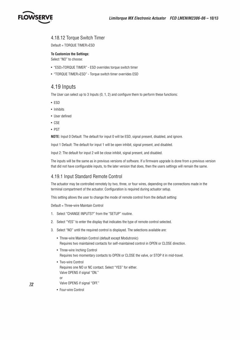
Limitorque MX Electronic Actuator FCD LMENIM2306-06 – 10/13
72
4.18.12 Torque Switch TimerDefault = TORQUE TIMER>ESD
To Customize the Settings:Select “NO” to choose:
• “ESD>TORQUE TIMER” - ESD overrides torque switch timer
• “TORQUE TIMER>ESD” - Torque switch timer overrides ESD
4.19 InputsThe User can select up to 3 Inputs (0, 1, 2) and configure them to perform these functions:
• ESD
• Inhibits
• User defined
• CSE
• PST
NOTE: Input 0 Default: The default for input 0 will be ESD, signal present, disabled, and ignore.
Input 1 Default: The default for input 1 will be open inhibit, signal present, and disabled.
Input 2: The default for input 2 will be close inhibit, signal present, and disabled.
The inputs will be the same as in previous versions of software. If a firmware upgrade is done from a previous version that did not have configurable inputs, to the later version that does, then the users settings will remain the same.
4.19.1 Input Standard Remote ControlThe actuator may be controlled remotely by two, three, or four wires, depending on the connections made in the terminal compartment of the actuator. Configuration is required during actuator setup.
This setting allows the user to change the mode of remote control from the default setting:
Default = Three-wire Maintain Control
1. Select “CHANGE INPUTS?” from the “SETUP” routine.
2. Select “YES” to enter the display that indicates the type of remote control selected.
3. Select “NO” until the required control is displayed. The selections available are:
• Three-wire Maintain Control (default except Modutronic) Requires two maintained contacts for self-maintained control in OPEN or CLOSE direction.
• Three-wire Inching Control Requires two momentary contacts to OPEN or CLOSE the valve, or STOP it in mid-travel.
• Two-wire Control Requires one NO or NC contact. Select “YES” for either. Valve OPENS if signal “ON.” or Valve OPENS if signal “OFF.”
• Four-wire Control

73
Limitorque MX Electronic Actuator FCD LMENIM2306-06 – 10/13
flowserve.com
4.19.2 StatusDefault Setting is: OFF
Select “NO” to choose whether the inhibit is “ON” or “OFF.”
4.19.3 Custom Input Mode #1 – Momentary ESD/PSESD (Optional)
Custom software is available for the MX that permits the User to establish certain performance characteristics for partial stroke (PS) testing and momentary contact closure ESD.
Note: These three inputs are normally configurable. However, when this custom mode is enabled, they are set to the predefined configuration and cannot be changed by the customer.
Input 0 (normal default – ESD) terminal 30:
• Set as disabled, user input function, signal present
Input 1 (normal default – Open Inhibit) terminal 34:
• Set as enabled, partial stroke enable function, signal present = active
Input 2 (normal default – Close Inhibit) terminal 35:
• Set as enabled, partial stroke enable function, signal absent = active
The partial stroke enable signals are setup as redundant signals for safety. There are two signal inputs, and BOTH must be in the active state. If the partial stroke enable inputs are in the active state, and an input is detected (>800 ms) on the momentary ESD/PSESD input, then a partial stroke ESD test will be run. If the partial stroke enable inputs are not active or in a fault state, and an input is detected on the momentary ESD/PSESD input, then the ESD will be latched in and the actuator will perform ESD until the ESD Release is given.
NOTE: These three inputs are the normal open-close-stop inputs. When this custom mode is enabled, they are set to the predefined configuration and cannot be changed by the customer. The only change the customer can make is to set the momentary ESD action (if action is position – then also the target value for the ESD) and the partial stroke target value.
Input 3 (normal default – stop) terminal 26:
• Set as enabled, ESD release function, signal absent = active
Input 4 (normal default – open) terminal 25:
• Set as enabled, ESD Release function, signal present = active
Input 5 (normal default – close) terminal 27:
• Set as enabled, momentary ESD/PSESD function, signal present > 800 ms = active, ESD action = Close, partial stroke target position = 0% open
The ESD release signals are setup as redundant signals for safety. There are two signal inputs, and BOTH must be in the active state. If there is an active ESD and both ESD release inputs are in the active state, the ESD will be unlatched and the unit will return to normal operation. If the ESD release inputs are in a fault state, an active ESD will NOT be released. The ESD release inputs will have no effect on a partial stroke ESD test. The momentary ESD/PSESD input will be ignored if there is a signal present for less than 100 ms, and is guaranteed to latch in the ESD/PSESD if the signal is present for greater than 800 ms. Once the ESD is latched in, the unit will perform the ESD action. In this case the ESD will move the unit to the close limit and remain in ESD mode until the ESD release indication is given using the ESD release inputs.

Limitorque MX Electronic Actuator FCD LMENIM2306-06 – 10/13
74
Figure 4.29 – Custom input modes
see
Note
4se
e No
te 5
see
Note
6
Note
4: T
he “
ESD
ACTI
ON”
men
u w
ill o
nly
appe
ar if
the
stat
us fu
nctio
n fo
r the
inpu
t is
“MOM
ENTA
RY E
SD/P
SESD
”.
Othe
rwis
e th
e “S
IGNA
L PR
ESEN
T” m
enu
will
retu
rn to
the
“CHA
NGE
INPU
TS”
men
u.
Note
5: T
he “
ESD
MOV
E TO
” m
enu
only
app
ears
if p
ositi
on is
cho
sen
as a
ctio
n .
Note
6: “
PS M
OVE
TO”
men
u on
ly a
ppea
rs if
the
stat
us fu
nctio
n of
the
inpu
t is
“MOM
ENTA
RY E
SD/P
SESD
”.
The
user
will
onl
y be
abl
e to
cha
nge
the
ESD
ACTI
ON (a
nd E
SD M
OVE
TO ta
rget
if E
SD a
ctio
n is
pos
ition
, and
the
PS M
OVE
TO s
ettin
gs w
hen
in th
is s
peci
al c
usto
m m
ode
1.Fo
llow
ing
are
the
prec
onfig
ured
set
tings
for e
ach
inpu
t.
CHAN
GEIN
PUTS
CHAN
GE S
TATU
SIN
PUT
(0)?
STAT
US(O
FF)?
INPU
T (1
)IN
PUT
(2)
INPU
T (3
)IN
PUT
(4)
INPU
T (5
)
(PSE
SD E
NABL
E)( M
OMEN
TARY
ESD
REL
EASE
)( M
OMEN
TARY
ESD
/PSE
SD)
(CLO
SE)
(OPE
N)(S
TOP)
(POS
ITIO
N)
(ABS
ENT)
(ON)
STAT
US F
UNCT
ION
USER
INPU
T?ES
D AC
TION
(IG
NORE
)-OK
?PS
MOV
E TO
O%
OPE
NES
D M
OVE
TO
XXX%
OPE
NSI
GNAL
(P
RESE
NT)-
OK?
YES
NO
YES
NO
YES
NO
YES
NO
YES
NO
YES
NO
YES
NO
YES
NO
INPU
T 0:
ON,
ESD
Tim
e De
lay
Rela
y, s
igna
l pre
sent
, ESD
act
ion
clos
ed.
INPU
T 1:
ON,
Use
r Inp
ut, s
igna
l pre
sent
INPU
T 2:
ON,
Use
r Inp
ut, s
igna
l pre
sent
INPU
T 3:
ON,
Sto
pIN
PUT
4: O
N, O
pen
INPU
T 5:
ON,
Clo
se
The
follo
win
g m
enus
will
app
ear i
f the
cus
tom
er h
as th
e cu
stom
mod
e in
put o
ptio
n, a
nd h
as e
nabl
ed c
usto
m m
ode
1 (in
rem
ote
cont
rol m
enu)
. Cus
tom
mod
e 2
is s
ame
as m
ode
1 ex
cept
ther
e is
no
PS s
eque
nce
avai
labl
e. S
ee T
able
4.1
.
CHAN
GEIN
PUTS
?CH
ANGE
IN
PUT
0?ST
ATUS
(ON)
- OK
?
INPU
T (1
)IN
PUT
(2)
(CLO
SE IN
HIBI
T)(O
PEN
INHI
BIT)
(BOT
H IN
HIBI
T)(U
SER
INHI
BIT)
-
See
Note
1
(OFF
)
STAT
US F
UNCT
ION
ESD
- OK?
Note
1: E
SD is
har
d od
ed fo
r INP
UT 0
. You
can
onl
y co
nfigu
re IN
PUTS
1 a
nd 2
for t
he o
ther
opt
ions
.No
te 2
: TDR
DEL
AY w
ill o
nly
show
for I
NPUT
0. A
ll ot
her i
nput
s th
is is
ski
pped
.No
te 3
: ESD
ACT
ION
men
u w
ill o
nly
appe
ar if
the
STAT
US F
UNCT
ION
for i
nput
s is
ESD
oth
erw
ise
the
SIGN
AL P
RESE
T m
enu
will
retu
rn to
the
CHAN
GE IN
PUTS
men
u.No
te 4
: The
ESD
MOV
E TO
men
u on
ly a
ppea
rs if
pos
ition
is c
hose
n as
act
ion.
YES
NONO
YES
NOYES
NOYES
INPU
T 0:
ON,
ESD
Tim
e De
lay
Rela
y, s
igna
l pre
sent
, ESD
act
ion
clos
ed.
INPU
T 1:
ON,
Use
r Inp
ut, s
igna
l pre
sent
INPU
T 2:
ON,
Use
r Inp
ut, s
igna
l pre
sent
INPU
T 3:
ON,
Sto
pIN
PUT
4: O
N, O
pen
INPU
T 5:
ON,
Clo
se
0-18
00 S
ECS
30 S
EC IN
CREM
ENTS
TDR
DELA
Y 0
SECS
- OK
?
YES NO
See
Note
2
See
Note
3Se
e No
te 4
ABSE
NT(IG
NORE
)(P
OSIT
ION)
(STO
P)(O
PEN)
SIGN
AL(P
RESE
NT)-
OK?
ESD
ACTI
ON(C
LOSE
)-OK
?ES
D M
OVE
TOXX
X% O
PEN
YES NO
YES NO
YES NO
The
follo
win
g m
enus
will
app
ear i
f the
cus
tom
er h
as th
e cu
stom
mod
e in
put o
ptio
n, a
nd h
as e
nabl
ed c
usto
m m
ode
3 (in
rem
ote
cont
rol m
enu)
.

75
Limitorque MX Electronic Actuator FCD LMENIM2306-06 – 10/13
flowserve.com
Figure 4.29 – Custom input modes
see
Note
4se
e No
te 5
see
Note
6
Note
4: T
he “
ESD
ACTI
ON”
men
u w
ill o
nly
appe
ar if
the
stat
us fu
nctio
n fo
r the
inpu
t is
“MOM
ENTA
RY E
SD/P
SESD
”.
Othe
rwis
e th
e “S
IGNA
L PR
ESEN
T” m
enu
will
retu
rn to
the
“CHA
NGE
INPU
TS”
men
u.
Note
5: T
he “
ESD
MOV
E TO
” m
enu
only
app
ears
if p
ositi
on is
cho
sen
as a
ctio
n .
Note
6: “
PS M
OVE
TO”
men
u on
ly a
ppea
rs if
the
stat
us fu
nctio
n of
the
inpu
t is
“MOM
ENTA
RY E
SD/P
SESD
”.
The
user
will
onl
y be
abl
e to
cha
nge
the
ESD
ACTI
ON (a
nd E
SD M
OVE
TO ta
rget
if E
SD a
ctio
n is
pos
ition
, and
the
PS M
OVE
TO s
ettin
gs w
hen
in th
is s
peci
al c
usto
m m
ode
1.Fo
llow
ing
are
the
prec
onfig
ured
set
tings
for e
ach
inpu
t.
CHAN
GEIN
PUTS
CHAN
GE S
TATU
SIN
PUT
(0)?
STAT
US(O
FF)?
INPU
T (1
)IN
PUT
(2)
INPU
T (3
)IN
PUT
(4)
INPU
T (5
)
(PSE
SD E
NABL
E)( M
OMEN
TARY
ESD
REL
EASE
)(M
OMEN
TARY
ESD
/PSE
SD)
(CLO
SE)
(OPE
N)(S
TOP)
(POS
ITIO
N)
(ABS
ENT)
(ON)
STAT
US F
UNCT
ION
USER
INPU
T?ES
D AC
TION
(IG
NORE
)-OK
?PS
MOV
E TO
O%
OPE
NES
D M
OVE
TO
XXX%
OPE
NSI
GNAL
(P
RESE
NT)-
OK?
YES
NO
YES
NO
YES
NO
YES
NO
YES
NO
YES
NO
YES
NO
YES
NO
INPU
T 0:
ON,
ESD
Tim
e De
lay
Rela
y, s
igna
l pre
sent
, ESD
act
ion
clos
ed.
INPU
T 1:
ON,
Use
r Inp
ut, s
igna
l pre
sent
INPU
T 2:
ON,
Use
r Inp
ut, s
igna
l pre
sent
INPU
T 3:
ON,
Sto
pIN
PUT
4: O
N, O
pen
INPU
T 5:
ON,
Clo
se
The
follo
win
g m
enus
will
app
ear i
f the
cus
tom
er h
as th
e cu
stom
mod
e in
put o
ptio
n, a
nd h
as e
nabl
ed c
usto
m m
ode
1 (in
rem
ote
cont
rol m
enu)
. Cus
tom
mod
e 2
is s
ame
as m
ode
1 ex
cept
ther
e is
no
PS s
eque
nce
avai
labl
e. S
ee T
able
4.1
.
CHAN
GEIN
PUTS
?CH
ANGE
IN
PUT
0?ST
ATUS
(ON)
- OK
?
INPU
T (1
)IN
PUT
(2)
(CLO
SE IN
HIBI
T)(O
PEN
INHI
BIT)
(BOT
H IN
HIBI
T)(U
SER
INHI
BIT)
-
See
Note
1
(OFF
)
STAT
US F
UNCT
ION
ESD
- OK?
Note
1: E
SD is
har
d od
ed fo
r INP
UT 0
. You
can
onl
y co
nfigu
re IN
PUTS
1 a
nd 2
for t
he o
ther
opt
ions
.No
te 2
: TDR
DEL
AY w
ill o
nly
show
for I
NPUT
0. A
ll ot
her i
nput
s th
is is
ski
pped
.No
te 3
: ESD
ACT
ION
men
u w
ill o
nly
appe
ar if
the
STAT
US F
UNCT
ION
for i
nput
s is
ESD
oth
erw
ise
the
SIGN
AL P
RESE
T m
enu
will
retu
rn to
the
CHAN
GE IN
PUTS
men
u.No
te 4
: The
ESD
MOV
E TO
men
u on
ly a
ppea
rs if
pos
ition
is c
hose
n as
act
ion.
YES
NONO
YES
NOYES
NOYES
INPU
T 0:
ON,
ESD
Tim
e De
lay
Rela
y, s
igna
l pre
sent
, ESD
act
ion
clos
ed.
INPU
T 1:
ON,
Use
r Inp
ut, s
igna
l pre
sent
INPU
T 2:
ON,
Use
r Inp
ut, s
igna
l pre
sent
INPU
T 3:
ON,
Sto
pIN
PUT
4: O
N, O
pen
INPU
T 5:
ON,
Clo
se
0-18
00 S
ECS
30 S
EC IN
CREM
ENTS
TDR
DELA
Y 0
SECS
- OK
?
YES NO
See
Note
2
See
Note
3Se
e No
te 4
ABSE
NT(IG
NORE
)(P
OSIT
ION)
(STO
P)(O
PEN)
SIGN
AL(P
RESE
NT)-
OK?
ESD
ACTI
ON(C
LOSE
)-OK
?ES
D M
OVE
TOXX
X% O
PEN
YES NO
YES NO
YES NO
The
follo
win
g m
enus
will
app
ear i
f the
cus
tom
er h
as th
e cu
stom
mod
e in
put o
ptio
n, a
nd h
as e
nabl
ed c
usto
m m
ode
3 (in
rem
ote
cont
rol m
enu)
.
4.19.4 Custom Input Mode #2 – Momentary ESD/CSE (Optional)Custom software is available for the MX that permits the user to establish certain performance characteristics momen-tary contact closure ESD and 4-wire remote control.
NOTE: These three inputs are normally configurable, however, when this custom mode is enabled, they are set to the predefined configuration and cannot be changed by the customer.
Input 0 (normal default – ESD) terminal 30: Set as remote stop
Input 1 (normal default – Open Inhibit) terminal 34: Set as remote close
Input 2 (normal default – Close Inhibit) terminal 35: Set as remote open
NOTE: These three inputs are the normal open-close-stop inputs. When this custom mode is enabled, they are set to the predefined configuration and cannot be changed by the customer. The only change the customer can make is to set the momentary ESD action (if action is position – then also the target value for the ESD).
Input 3 (normal default – Stop) terminal 26: Set as enabled, ESD release function, signal absent = active
Input 4 (normal default – Open) terminal 25: Set as enabled, ESD Release function, signal present = active
Input 5 (normal default – Close) terminal 27: Set as enabled, momentary ESD function, signal present > 800 ms = active, ESD action = Close.
The ESD release signals are setup as redundant signals for safety. There are two signal inputs, and BOTH must be in the active state. If there is an active ESD and both ESD release inputs are in the active state, the ESD will be unlatched and the unit will return to normal operation. If the ESD release inputs are in a fault state, an active ESD will NOT be released. The ESD release inputs will have no effect on a partial stroke ESD test. The momentary ESD input will be ignored if there is a present for less than 100 ms, and is guaranteed to latch in the ESD if the signal is present for greater than 800 ms. Once the ESD is latched in, the unit will perform the ESD action. In this case the ESD will move the unit to the close limit and remain in ESD mode until the ESD release indication is given using the ESD release inputs.
4.19.5 Custom Input Mode #3 – ESD Time Delay RelayCustom software is available for the MX that permits the User to establish certain performance characteristics for ESD.
NOTE: These three inputs are normally all configurable. However, when this custom mode is enabled, the customer still retains the ability to change inputs 1 and 2 to their choosing, but Input 0 will always remain ESD. The timer is default 0-30 min (30 sec increment with default 0 sec).
Input 0 (normal default – ESD) terminal 30: Set as enabled, ESD, 0 sec Delay(default), Signal present = active, ESD action Close
Input 1 (normal default – Open Inhibit) terminal 34: Set as enabled, User Input, Signal present = active
Input 2 (normal default – Close Inhibit) terminal 35: Set as enabled, User Input, Signal present = active

Limitorque MX Electronic Actuator FCD LMENIM2306-06 – 10/13
76
The ESD Time Delay Relay input (input 0) functions like any normal ESD input signal. Only if a time has been entered into the Delay Timer value then the unit will not act on that ESD for that delayed amount of time. If the ESD signal is removed, then the timer is canceled and will start fresh with the next assertion. You cannot change that Input 0 is ESD, but it can be enabled/disabled, set to signal present/absent, or you can change the ESD action.
NOTE: These three inputs are kept as open-stop-close inputs. When the custom mode is enabled, the wire mode is preset to 4-wire control and cannot be altered.
Input 3 (normal default – Stop) terminal 26Input 4 (normal default – Open) terminal 25Input 5 (normal default – Close) terminal 27
4.19.6 Custom Input Mode #4 - Multi-position Mode (Optional)Custom software is available for the MX that permits the User to establish certain performance characteristics for Multi Position controls for remote and local operations.
Input 0 (normal default - ESD) terminal 30: •SetasenabledMlMoveTo,signalpresent=active
Input 1 (normal default - Open Inhibit) terminal 34: •Setasdisabled,UserInput,signalpresent=active
Input 2 (normal default - Close inhibit) terminal 35: •Setasdisabled,UserInput,signalpresent=active
The custom input Multi Position Mode allows the user to configure up to 2 mid travel stop positions. The user will be able to send the actuator to either of these positions in either remote or local controls. In order to use local controls in multi-mode, that option will need to be selected in the CHANGE LOCAL Control menu. The user can select any of the standard wire controls for inputs 3, 4, and 5 (4-wire, 3- wire Maintain, or 3-wire Inching).
Figure 4.30 – Inputs
OFF-OK?
OFF-OK?
(OFF)
(CLOSE INHIBIT)(OPEN INHIBIT)(BOTH INHIBIT)(USER INPUT)
0-1800 SECS30 SEC INCREMENTS
See Note 4
See Note 5
See Note 6 See Note 7
ABSENT (IGNORE)(POSITION)(STOP)(OPEN)
See Note 3
NOTE 1: The custom mode will only appear if the if the custom mode option has been enabled.NOTE 2: The "open if signal" menu will only appear, if 2-wire option is chosen. Two wire control is not permitted if the user has modutronic or network control (DDC, FF, PB PA, PB DP, or Device Net).NOTE 3: The number of inputs displayed for configuration will depend upon the mode selected (standard, negative switching, or custom).NOTE 4: ESD is hard oded for INPUT 0. You can only configure INPUTS 1 and 2 for the other options.NOTE 5: TDR DELAY will only show for INPUT 0. All other inputs this is skipped.NOTE 6: ESD ACTION menu will only appear if the STATUS FUNCTION for inputs is ESD otherwise the SIGNAL PRESET menu will return to the CHANGE INPUTS menu.NOTE 7: The ESD MOVE TO menu only appears if position is chosen as action.NOTE 8: The user must select yes for the Save Settings menu, or the changes made in these menus will not be saved.NOTE 9: The SIL mode will only appear if one of the SIL modes has been enabled.NOTE 10: Wire modes does not appear for enhanced SIL.
INPUT 0: ON, ESD Time Delay Relay, signal present, esd action closed.INPUT 1: ON, User Input, signal presentINPUT 2: ON, User Input, signal presentINPUT 3: ON, StopINPUT 4: ON, OpenINPUT 5: ON, Close
See Note 1
MODE 3-WIRE INCHMODE 2-WIRE
MODE USER INPUTMODE 4-WIRE
See Note 2
See Note 2
See Note 8
MODE 3-WIRE INCHMODE 2-WIRE
MODE USER INPUTMODE 4-WIRE
CHANGEINPUTS
STANDARDREMOTE CONTROL
NEGATIVESWITCHING
MODE 3-WIREMAINT-OK
MODE 3-WIREMAINT-OK?
CHANGEINPUT(0)?
STATUS(ON) - OK?
STATUS FUNCTION ESD - OK?
TDR DELAY 0 SECS - OK?
SIGNAL(PRESENT)-OK?
SAVE SETTINGS?
ESD ACTION(CLOSE)-OK?
ESD MOVE TOXXX% OPEN
OPEN IF SIGNALON-OK?
CUSTOMCONTROL
CUSTOM MODE1-0K?
CUSTOM MODE2-0K?
CUSTOM MODE3-0K?
OPEN IF SIGNALON-OK?
CHANGEINPUT (5)?
YES
NO
YES
NO
YES
NO
YES
NO
YES
NO
YES
NO
YES
NO
YES
NO
YES
NO
YES
NO
YES
NO
YES
NO
YES
NO
YES
NO
YES
NO
YES
NO
YES
NO
YES
NO
CUSTOM MODE4-0K?
YES
NO
YES
NO
YES
NO

77
Limitorque MX Electronic Actuator FCD LMENIM2306-06 – 10/13
flowserve.com
Figure 4.31 – Inputs
4.19.7 Limigard ControlsThe Limigard controls is available for the MX that presents the user with redundant inputs at Inputs a and 5 for close, Inputs 1 and 4 for open, and Inputs 2 and 3 for stop. Both inputs need to be asserted in order for the actuator to move open or close. Only 1 stop input needs to be asserted in order for the actuator to stop.
NOTE: These three inputs are normally configurable, however, when this custom mode is enabled, they are set to the predefined configuration and cannot be changed by the customer.
Input a (normal default - ESO) terminal 30: Set as remote close
Input 1 (normal default · Open Inhibit) terminal 34: •SetasremoteopenInput 2 (normal default - Close Inhibit) terminal 35: •Setasremotestop
Input 3 (normal default - Stop) terminal 26:Input 4 (normal default - Open) terminal 25:Input 5 (normal default - Close) terminal 27:
4.19.8 SIL Mode – Standard SIL (Optional)Custom software is available for the MX that permits the User to establish certain performance characteristics for partial stroke (PS) testing and ESD.
NOTE: These three inputs are normally configurable. When this SIL mode is enabled, input 0 is preconfigured to ESD, input 1 is pre-configured to partial stroke, and both inputs cannot be changed by the customer. Input 2 can be configured to user input, inhibit, ESD or CSE.
Input 0 (normal default - ESD) terminal 30: •Setasenabled,ESD,signalpresentInput 1 (normal default - Open Inhibit) terminal 34: •Setasenabled,partialstrokefunction,signalpresent=activeInput 2 (normal default - Close Inhibit) terminal 35: •Setasdisabled,userinput,signalabsent=active
When this mode is selected, the ESD overrides are set so that ESD had priority over stop, local, and network ESD. You cannot change that Input 0 is ESD, but it can be enabled/disabled, set to signal present/absent, or you can change the ESD action.
NOTE: These three inputs are kept as open-stop-close inputs. When the custom mode is enabled, the wire mode is preset to 4-wire control and cannot be altered.
Input 3 (normal default - stop) terminal 26 Input 4 (normal default - open) terminal 25 Input 5 (normal default - close) terminal 27
CHANGEINPUTS
MODE4-WIRE OK?
MULTI POSITION2 OK?
CHANGEINPUT-0?
STATUS(ON)-OK?
M1 MOVE TO(XXX%) OPEN?
PROP BAND(XXX%) OPEN
DEAD BAND(XXX%) OPEN
(OFF)
NOTE 1: If using 1 Multi Position then Input 0 will be set as your M1 Move To and Inputs 1 and 2 are standard configurable. If 2 Multi Positions are used then Input 1 is set as your M2 Position and input 2 is standard configureable.
INPUT 0: ON, M1 Move To, signal presentINPUT 1: OFF, User Input, signal presentINPUT 2: OFF, User Input, signal presentINPUT 3: ON, STOPINPUT 4: ON, OPENINPUT 5: ON, CLOSE
SEE NOTE 13 WIREMAINT
3 WIRE INCH
Limitorque MX Electronic Actuator FCD LMENIM2306-06 – 10/13
78
Figure 4.32 – SIL control (standard)
4.19.9 SIL Mode – Enhanced SIL (Optional)Custom software is available for the MX that permits the User to establish certain performance characteristics for partial stroke (PS) testing and momentary contact closure ESD.
NOTE: These three inputs are normally configurable. When this SIL mode is enabled, input 0 is configurable to 2 wire control, user defined or inhibit. Inputs 1 and 2 are pre-configured for partial stroke enable and cannot be changed by the customer.
Input 0 (normal default - ESD) terminal 30: •Setasdisabled,userinputfunction,signalpresent
Input 1 (normal default - Open Inhibit) terminal 34: •Setasenabled,partialstrokeenablefunction,signalpresent=active
Input 2 (normal default - Close Inhibit) terminal 35: •Setasenabled,partialstrokeenablefunction,signalabsent=active
The partial stroke enable signals are setup as redundant signals for safety. There are two signal inputs, and BOTH must be in the active state. If the partial stroke enable inputs are in the active state, and an input is detected (>800 ms) on the momentary ESD/PSESD input, then a partial stroke ESD test will be run. If the partial stroke enable inputs are not active or in a fault state, and an input is detected on the momentary ESD/PSESD input, then the ESD will be latched in and the actuator will perform ESD until the ESD Release is given.
NOTE: These three inputs are the normal open-close-stop inputs. When this custom mode is enabled, they are set to the predefined configuration and cannot be changed by the customer. The only change the customer can make is to set the momentary ESD action (if action is position - then also the target value for the ESD) and the partial stroke target value.
SIL CONTROLSTANDARD?
STATUS(ON)-OK?
STATUS FUNCESD-OK?
MODEUSER INPUT?
CHANGEINPUT-0?
CHANGEINPUT 1?
NOTE 1: Input 2 can be configured like any standard input, i.e. inhibits. ESO, user inputNOTE 2: The ESO MOVE TO menu only appears of position is chosen an action.
SEE NOTE 2
SEE NOTE 1
ABSENT
STOPOPENCLOSEIGNORE
4-Wire3-Wire Main3-Wire Inch
2-WireUser Input
YES
NO
YES
OFF
YES
YES
YES
YES
YES YES YES
CHANGEINPUT-2?
SAVESETTINGS?
NO
SIGNALPRESENT-OK?
NO
ESD ACTIONPOSITION-OK?
NO
MOVE TOXXX%-OK?
NO
PROP BANDXXX%-OK?
DEAD BANDXXX%-OK?
NO NO
STATUS(ON)-OK?
ABSENT
YES YES
OFF
YES
YES
YES YES YES
STATUS FUNCPARTIAL STROKE
NO
SIGNALPRESENT-OK?
NO
PS MOVE TOXXX%-OK?
NO
PROP BANDXXX%-OK?
NO
DEAD BANDXXX%-OK?
NO

79
Limitorque MX Electronic Actuator FCD LMENIM2306-06 – 10/13
flowserve.com
Input 3 (normal default - stop) terminal 26: •Setasenabled,ESDreleasefunction,signalabsent=active
Input 4 (normal default - open) terminal 25: •Setasenabled,ESDReleasefunction,signalpresent=active
Input 5 (normal default - close) terminal 27: •Setasenabled,momentaryESD/PSESDfunction,signalpresent>800ms=active,ESDaction=
Close, partial stroke target position = 0% open The ESD release signals are setup as redundant signals for safety. There are two signal inputs, and BOTH must be in the active state. If there is an active ESD and both ESD release inputs are in the active state, the ESD will be unlatched and the unit will return to normal operation. If the ESD release inputs are in a fault state, an active ESD will NOT be released. The ESD release inputs will have no effect on a partial stroke ESD test. The momentary ESD/PSESD input will be ignored if there is a signal present for less than 100 ms, and is guaranteed to latch in the ESD/PSESD if the signal is present for greater than 800 ms. Once the ESD is latched in, the unit will perform the ESD action. In this case the ESD will move the unit to the close limit and remain in ESD mode until the ESD release indication is given using the ESD release inputs.
Figure 4.33 – SIL control (Enhanced)
SIL CONTROLENHANCED?
STATUS(OFF)-OK?
STATUS(OFF)-OK?
STATUS FUNCUSER INPUT-OK?
SIGNALPRESENT-OK?
CHANGEOUTPUT 0?
CHANGEINPUT-0?
VIEWDIAGNOSTICS?
YES AND2 WIRE
OPEN INHIBITCLOSE INHIBITBOTH INHIBIT2-WIRE OPEN2-WIRE CLOSE
NOTES:NOTE 1: 2 Wire controls are not selectable is DDC, PBCP, PBPA,Devicenet, FF, or Maclulating controls are enabled.
SEE NOTE 1
YES ANDNOT 2 WIRE
SEE NOTE 1
ABSENT
YES AND NOT POSITION
IGNORECLOSEOPENSTOP
YES
YES YES
OFF
YES YES YES YES
YES
YES
YES
ABSENTNO
NO NONO
STATUS FUNC USERMO ESD/PSESO-OK?
NO
SIGNALPRESENT-OK?
NO
ESD ACTIONPOSITION-OK?
NO
ESD MORE TOXXX%-OK?
NO
PROP BANDXXX%-OK?
NO
DEAD BANDXXX%-OK?
NO
PS MOVE TOXXX%-OK?
NO
YES

Limitorque MX Electronic Actuator FCD LMENIM2306-06 – 10/13
80
Table 4.1 – Digital input terminalsNegative Switching (Positive Earth)
Mode Input 0 Input 1 Input 2 Input 3 Input 4 Input 5
2-wire configurable open not used configurable not used not used
3-wire inch close open not used configurable not used not used
3-wire maint close open not used configurable not used not used
4-wire close open not used stop not used not used
User Input configurable configurable not used configurable not used not used
Terminal connections
Input 0 Input 1 Input 2 Input 3 Input 4 Input 5
+VDC -VDC +VDC -VDC +VDC -VDC +VDC -VDC +VDC -VDC +VDC -VDC
30 32 34 29 N/A N/A 26 28 N/A N/A N/A N/A
Custom Modes
Mode Input 0 Input 1 Input 2 Input 3 Input 4 Input 5
1 not used PS Enable 1 PS Enable 2 ESD Release 2 ESD Release 1 MO ESD/PSESD
2 stop close open ESD Release 2 ESD Release 1 MO ESD
3 ESD TDR configurable configurable stop open close
(MO - momentary signal)
4 M1 Position M2 Position configurable stop open close
Terminal connections
Input 0 Input 1 Input 2 Input 3 Input 4 Input 5
+VDC -VDC +VDC -VDC +VDC -VDC +VDC -VDC +VDC -VDC +VDC -VDC
30 32 or 33 34 29 or 31 35 29 or 31 26 28 25 28 27 28
Jumpers can be used to connect the digital commons as needed. 28 to 29, 31 to 32, 33, to VDC source common.
Limigard Mode
Mode Input 0 Input 1 Input 2 Input 3 Input 4 Input 5
close open stop stop open close
Sil Modes
Mode Input 0 Input 1 Input 2 Input 3 Input 4 Input 5
Standard ESD Partial Stroke Test configurable stop open close
Enhanced configurable PS Enable 1 PS Enable 2 ESD Release 2 ESD Release 1 MO ESD/PSESD

81
Limitorque MX Electronic Actuator FCD LMENIM2306-06 – 10/13
flowserve.com
4.2 Monitor RelayThe monitor relay indicates the actuator is available for remote operation. The monitor relay will de-energize on loss of power or if any of the following functions become active:
Normal operationEach selection is User configurable. Select “Enabled” to turn the feature on, and “Disabled” to turn the feature off.
• “LOCAL STOP/OFF” – Red selector knob in “STOP/OFF”
• “LOCAL SELECTED” – Red selector knob in “LOCAL”
• “TORQUE TIMER” - if enabled
Fault indicationEach selection is User configurable. Select “Enabled” to turn the feature on, and “Disabled” to turn the feature off.• “LOST PHASE” – Single phasing
• “VALVE JAMMED” – Valve cannot move when energized to pull out of valve seat
• “MOTOR OVERTEMP” – Thermistor range exceeded
The yellow LED will blink when monitor relay is de-energized.
Figure 4.34 – SIL control (Enhanced)
YES YES YES
YES YES YES
YES YES YES YES
NO NO NO NO
NONO NO
NO NONO
CHANGEMONITOR RELAY?
SELECT SETTINGS?
L0CALENABLED-OK?
ENABLED-OK? ENABLED-OK? ENABLED-OK?DISABLED-OK?DISABLED-OK?
DISABLED-OK? DISABLED-OK?DISABLED-OK?
LOCAL STOP ENABLED-OK?
INHIBIT SIGNALDISABLED-OK
ESD SIGNAL DISABLED-OK?
PS ENABLE ACTIVEENABLED-OK?
PS ENABLE FAULTENABLED-OK?
ESD RELEASE FAULTENABLED-OK?
OVERTORQUE DISABLED-OK?
The three following options will only show if the customer haspurchased and enabled custom option 1 or enhanced SIL.
These functions are monitored continuously and may not be changed, but an additional three functions may be configured individually during setup.
1. Select “CHANGE MONITOR RELAY?” from the “SETUP” routine.
2. Select “YES” to enter the “SELECT SETTINGS?” display. Select “YES” to access each of the following three functions:
• “OVERTORQUE” – Torque range exceeded in mid-travel, thermistor temperature exceeded, or malfunction in thermistor
• “INHIBIT SIGNAL” – Inhibit “ON” and active
• “ESD SIGNAL” – ESD “ON” and active
3. Select “NO” to:
• “ENABLED” – will trip monitor relay or
• “DISABLED” – will not trip monitor relay.

Limitorque MX Electronic Actuator FCD LMENIM2306-06 – 10/13
82
4.21 Diagnostic ResetFor diagnostic purposes the following parameters are recorded at certain points in the valve travel on every opening and closing stroke:
• Proportional measurements of torque
• Drive sleeve turns
• Contactor operations
• Maximum and minimum voltage
• Motor run time
• Stroke time
To enable the new values to be compared with previous measurements, it is essential to record reference values. Limitorque recommends this be done after the valve has been installed, commissioned, and is operating under normal process conditions, and after a plant shutdown or actuator/valve overhaul. The user may select to reset the torque profile at any time.
1. Select “RESET TORQUE PROFILE?” from the “RESET DIAGNOSTICS” routine.
2. Select “YES” to enter the “SAVE NEXT CYCLE?” display.
3. Select “NO” to switch the reset ON or OFF.
After the next complete cycling of the valve, in both the open and close directions, this reset will automatically be switched OFF.
4. Select “RESET COUNTERS” to reset all the listed parameters to “0.”
Figure 4.35 – Diagnostic reset
YES YES
YES
NO
NO
YES
NO NO
Resets: Drive sleeve turns Contactor operations Maximum voltage Minimum voltage Motor run time Stroke time
CHANGE DIAGNOSTICSRESET?
RESET TORQUE PROFILE?
RESET COUNTERS OK?
SAVE NEXT CYCLE OK?

83
Limitorque MX Electronic Actuator FCD LMENIM2306-06 – 10/13
flowserve.com
4.22 TAG NumberDefaults to blanks.
To Customize the Setting:1. Select “CHANGE TAG?” from the “SETUP” routine.
2. Select “YES” to enter the “ENTER DIGIT” displays.
3. Select “NO” to choose the required number or letter for each digit of the valve tag number, up to a maximum number of 16 digits.
The alphanumeric display scrolls from a symbol set, numerals and then A-Z in the following order: ! “ # $ % @ ‘ ( ) * + , - . / 0-9 : ; < = > ? A-Z. There is one blank at each end to enable a tag number with less than 16 digits to be entered clearly. To highlight the digit being entered, a dot appears over the space and the letter above the space disappears.
Figure 4.36 – TAG number
YES YES YE S
NO NO
YES YES/NO
“ NO ” changes digi t
NO NO
Same procedure for digits 3-16
YES
Up to 16 digits ma y be used. Alpha- numerics 0-9, then A-Z, plus blanks
Blank space appears first, then alphanumerics
This allows easy entry for tags of less than 16 digits
“ NO ” changes digit
CHANGE TAG?
ENTER DIGIT #1 "0"------_
ENTER DIGIT #2 MO “0”-----
ENTER DIGIT #16 M OOOOOOOOO“0”
RECORD TAG OK?
4.23 LCD ContrastPermits adjustment of the viewing contrast of the LCD.
1. Select “YES” to enter the “LCD CONTRAST” display.
2. Select “NO” to adjust contrast to desired level.
Figure 4.37 – LCD contrast
YES YES
NO NO “ NO ” adjusts LCD contrast
CHANGE LCD C ONTRAST?
LCD CONTRAST OK ?
4.24 Torque Boost – only available for arctic temperature actuators
Default = “AUTO”
Torque boost increases the capacity to move valves under conditions of low temperature or extreme valve stiffness. In the default setting, the MX will permit more output torque up to the unit’s maximum torque rating when the tempera-ture falls below 32°F (0°C). When configured as ON, torque boost will be present under all conditions regardless of temperature, and when OFF, torque boost will not be present.

Limitorque MX Electronic Actuator FCD LMENIM2306-06 – 10/13
84
Figure 4.38 – Torque boost
YE S YES
“ NO ” toggles options
NO (ON) (OFF)
CHANGE TORQUE BOOST?
TORQUE BOOS T (AUTO)-OK?
4.25 Motor Thermostat The thermostat setting may be customized:
1. Select “CHANGE MOTOR THERMOSTAT?” from the “SETUP” routine.
2. Select “YES” to enter the “MOTOR THERMOSTAT” display.
3. Select “NO” to choose between “ENABLED” and “DISABLED.”
In the “DISABLED” mode, the motor thermostat is bypassed and detection of an overheated motor does not prevent operation of the actuator. This feature is user-selected when required by the application and may be desirable during critical service.
NOTE: If the motor thermostat is disabled, third party certification including Factory Mutual, CSA, ANeZ, ATEX, and warranty, will be voided.
Figure 4.39 – Motor thermostat
YES YES
NO NO (DISABLED )
CHANGE MOTOR THERMOSTAT?
THERMOSTAT (ENABLED)-OK?
4.26 Change Valve Data“Change Valve Data” allows the user to identify the type of valve the MX actuator is mounted to.
• Select “YES” to “Change Valve S/N?” Then select “YES” to “ENTER DIGIT” displays.
• Select “NO” to choose the required number or letter for each digit of the valve S/N, up to a maximum of 16 digits.
• Select “YES” when the desired number or letter is displayed. When all digits have been entered select “YES” to “Record S/N OK?”
• Follow same sequence for “CHANGE VALVE MODEL #?”, “CHANGE VALVE TYPE?”
• If “YES” to “CHANGE VALVE TYPE?” then “VALVE TYPE UNDEFINED-OK?” is displayed. “VALVE TYPE UNDEFINED-OK?” is only shown until the valve type is chosen. In the rare event that the user would need to “REINITIALIZE” the MX actuator, the screen will reappear. See Figure 5.1.
• The alphanumeric display scrolls from a symbol set, numerals and then A-Z in the following order: ! “ # $ % & ‘ ( ) * + , - . / 0-9 : ; < = > @ A-Z. There is one blank at each end to enable a tag number with less than 16 digits to be entered clearly. To highlight the digit being entered, a dot appears over the space and the letter above the space disappears.

85
Limitorque MX Electronic Actuator FCD LMENIM2306-06 – 10/13
flowserve.com
Figure 4.40 – Change valve data
CHANGE VALVE DATA?
CHANGE VALVE S/N?
CHANGE VALVE MODEL #?
CHANGE VALVE TYPE?
VALVE TYPE UNDEFINED1-OK?
ENTER DIGIT #2
ENTER DIGIT #16 OK?
ENTER DIGIT #1
NO
NO
NOLinear Rotary Other
YES YES
YES/NO
YES
NO
YES
NO
YES
NO
YES
Change Character
NOChange Character
NOChange Character
S/N MODEL # TYPE
RECORD n Same Procedure for digits
3–16.
NOTE 1: Valve type "UNDEFINED"is only shown until the valve type is chosen. After that, it will not be displayed again unless Reinitialized.
YESYES
4.27 Change PortThe MX can have new firmware loaded via the local port connections (refer to wiring diagram) or via the IRdA port, located on the LCD board and accessible via the sight glass. If supplied, enable the optional “Bluetooth Port” for remote configuration and access of DIagnostic information.
Both ports cannot be enabled simultaneously as they both share the same serial port on the main board.
Default = Local Port
Figure 4.41 – Change port and Bluetooth settings
CHANGEPORTS?
“NO” toggles optionsIRDA-OK?
NONE-OK?
DIAGNOSTIC PORTBLUETOOTH-OK?
BLUETOOTHPRESENT-OK?
ADDRESS-OK?0CW0961586E2
BLUETOOTHTAG
FCC IDENTIFICATIONPOOWML-C40
BLUETOOTHLICENSE
CHANGEBLUETOOTH?
LOCAL PORT(ON)-OK?
NO
YES
BLUETOOTH NAMEUSE UNIT S/N-OK?
USE UNITTAG-OK?
NO
YES
SECURITYENABLED-OK?
CHANGEBLUETOOTH PIN
NO
YES
DISCOVERYENABLED-OK?
DISABLED-OK? DISABLED-OK?
ENTER DIGIT #1default123456789
15 character pin/passkey –no changes the character,yes goes to the next digit.
Diagnostic use only
NO
YES
NO
YES
YES/NO YES/NO YES/NO
NO
YES
NO
YES
NO

Limitorque MX Electronic Actuator FCD LMENIM2306-06 – 10/13
86
5 Troubleshooting
c WARNING: This actuator is non-intrusive. Do not open the control compartment on the actuator unless absolutely necessary. It was sealed in dry, clean conditions in the factory and entry to this compartment should not be neces-sary. Unauthorized entry could void the warranty.
If the actuator will not operate, before attempting to troubleshoot, verify the following:
• LCD display reads “XX% OPEN,” “STATUS OK.”
• Red selector switch is not in the STOP position.
• All three phases of the main power supply are present at the actuator terminals.
• The supply voltage is the same as that stated on the actuator nameplate.
• Optional 110 VAC is measured at terminals 23 and 24.
• 24 VDC is measured at terminals 22 (+Ve) and 21.
• If 24 VDC power supply is ON, check that the loading does not exceed 5 W across terminals 21 and 22 (remove wires from 21, 22, 23, and 24).
• LCD and LED display on the control panel are illuminated.
If these checks are satisfactory, then attempt to locate the fault using the “VIEW DIAGNOSTICS” routine. It is also recommended that the actuator settings be verified using “VIEW SETTINGS.”
5.1 View Diagnostics Routine1. Enter “VIEW DIAGNOSTICS” as detailed in Section 5.3, View Diagnostics.
2. Review the various displays to try to find the reason the actuator will not operate. The displays that may help to isolate the fault are as follows:
• View Hardware Status
• View Motor Status
• View Power Supply
5.2 Troubleshooting Problems/Corrective Action(Refer to LMENIM2314, MX Maintenance and Spare Parts and the standard wiring diagram in the Section 3.3, Electrical Connections). We recommend that only Limitorque service personnel perform this operation.
1. Switch off the main power supply and 24 VDC supply at terminals 6 and 7 (if used).
2. Remove control compartment cover (ACP) and protect against the ingress of moisture or dust.
3. Remove any wiring that has been connected to terminals 21, 22, 23 and 24.

87
Limitorque MX Electronic Actuator FCD LMENIM2306-06 – 10/13
flowserve.com
4. Switch on main power supply.
5. Measure VAC at 23, 24 – should be 110 VAC if actuator is supplied with optional 110 VAC circuit. If no power, check fuses FS1, FS2 (600 VAC, 1 A, fast acting, 10.3 x 38.1 mm tube) and FS3 (250 VAC, 0.1A, time delay, 5 x 20 mm glass tube) and replace if necessary. If replacing fuses does not fix the problem, replace damaged board. Contact Limitorque Service at (434) 528-4400.
6. Measure VDC at 21, 22 – should be 24 VDC, maximum power of 5W. If not, replace damaged board.
7. Replace the control compartment cover (ACP).
5.2.1 Actuator Fails to Operate
Actuator Fails to Operate from LOCAL Controls1. Place the red selector knob in “LOCAL.”
2. If motor runs but actuator output does not turn, check that declutch lever has returned to motor operation position.
3. Check LCD display for following alarms:• If motor runs but no actuator movement is detected, check if the display says “JAMMED VALVE” and free if
necessary.
• Inhibit signal may be present or absent at the terminals. Check for signal and adjust as necessary. “INHIBIT ACTIVE” appears on display.
• Thermal overload of the motor may have been detected. Check motor for high temperature. Thermal overload is self-resetting when motor cools. “MOTOR OVERTEMP” appears on the display.
4. Check to see if the position limits are set incorrectly on top of one another. See Section 3.5.4, Setting Position Limits.
Actuator Fails to Operate from REMOTE Controls1. Check that the actuator will operate from “LOCAL.” If not, then carry out the checks described below.
2. Check that the red knob is in “REMOTE.”
3. ESD signal may be present or absent at the terminals. Check for signal and adjust as necessary. (“ESD ACTIVE” at display.) If actuator was previously operated in “LOCAL,” then the fault is probably in the remote control circuit. Check the integrity of the cabling and that the connections to the terminals are in accordance with the wiring diagram. If motor runs in “LOCAL,” but not “REMOTE,” adjust ESD to be greater than local (“ESD>LOCAL”).
4. Confirm correct monitor relay operation. See Table 3.5.
5.2.2 Jammed Valve Detected1. Check that position limits have been set correctly. If valve is position-seated, the limits should stop the motor just
before the end-of-travel. Recalibrate the position limits if necessary. See Section 3.5.4, Setting Position Limits.
2. Check that torque settings are correct for the valve. Recalibrate if necessary. See Section 4.6, Torque Setup.
3. Check the condition of the valve and lubrication of the valve stem and thrust bearings. The valve may have remained in the same position for a long time and become corroded internally or externally. Engage manual over-ride and employ the handwheel drive to unseat the valve.
4. Verify that the actuator will now operate the valve. Open and close the valve a few times to check for correct opera-tion throughout the travel.
NOTE: To free a jammed valve from the “CLOSE” or “OPEN” position, engage manual override and attempt to unseat it using the handwheel drive. If a rising stem valve is jammed in the close position, loosen the fixing bolts that attach the thrust base to the valve. This will release the compression in the drive components and reduce the effort to unjam the valve. Partly open the valve, then retighten the bolts.

Limitorque MX Electronic Actuator FCD LMENIM2306-06 – 10/13
88
5.2.3 Actuator Operates but Does Not Drive Valve1. Verify that the declutch lever has returned to motor-operated position.
2. Verify that the stem nut is fitted correctly in the actuator base.
3. Verify that the stem nut has sufficient engagement with the valve stem.
4. Verify that the key is fitted in bore/keyway applications.
5.2.4 Valve Does Not Seat Correctly1. Verify that position limits are calibrated correctly for the valve travel.
2. Verify that the torque-seating valves have been configured to close on torque, not position.
3. Verify that closing torque value has been set high enough to suit the process conditions.
4. Verify that the valve is not obstructed.
5.2.5 Status MessagesNormal display status is listed in Section 3.6.5, Local Indication. Status or alarm messages are listed below. Once a status or alarm condition occurs, the message will be displayed on the bottom line of the Local Control Station (LCS) screen until the condition is addressed and cleared. If multiple status or alarm conditions are active, the bottom display will cycle through each screen until the condition is addressed and cleared (one message per four seconds).
Status or Alarm Messages (XX = Input # (0, 1, 2))“---% OPEN, STATUS OK” – Normal display
“---% OPEN, VALVE JAMMED” – Valve cannot start moving
“---% OPEN, LOST PHASE” – One of three phases lost
“---% OPEN, MOTOR OVERTEMP” – Thermistor range exceeded
“---% OPEN, OVERTORQUE” – Torque exceeded in mid-travel
“---% OPEN, HARDWARE FAILURE” – Indication
“---% OPEN, DDC OFF” – DDC enabled, but “OFF”
“---% OPEN, ESD ACTIVE” – ESD signal present
“---% OPEN, INHIBIT ACTIVE” – Inhibit signal present
“---% OPEN, FF OFF” – FF enabled but “OFF”
“---% OPEN, PB OFF” – PB enabled but “OFF”
“---% OPEN, DN OFF” – DN enabled but “OFF”
“---% OPEN, WARMING UP” – Warm up delay active (cold temperature option)
“---% OPEN, NO ANALOG SIGNAL” – 4-20 mA signal absent (Mod enabled, red selector switch in “REMOTE”)
“---% OPEN, DDC COM LOST” – DDC enabled, signal absent
“---% OPEN, THERMISTOR” – There is a failure with the motor thermistor
“---% OPEN, KNOBS” – There is a failure with the local knobs
“---% OPEN, DDC NOT PRESENT” – DDC board expected but not found (missing or not communicating)

89
Limitorque MX Electronic Actuator FCD LMENIM2306-06 – 10/13
flowserve.com
“---% OPEN, FF NOT PRESENT” – FF board expected but not found
“---% OPEN, PBDP NOT PRESENT” – Profibus DP board expected but not found
“---% OPEN, PBPA NOT PRESENT” – Profibus PA board expected but not found
“---% OPEN, DN NOT PRESENT” – Device Net board expected but not found
“---% OPEN, ANG1 NOT PRESENT” – Analog 1 board expected but not found
“---% OPEN, ANG2 NOT PRESENT” – Analog 2 board expected but not found
“---% OPEN, CONTACTOR” – Contactor failure
“---% OPEN, ENCODER” – Encoder failure
“---% OPEN, R1R4RM RLY FAILED” – R1-R4 board relay check failed
“---% OPEN, R5R8 RLY FAILED” – R5-R8 board relay check failed
“---% OPEN, DDC FAILED” – Communication with the main board failed, or hardware fault
“---% OPEN, FF FAILED” – Communication with the main board failed, or hardware fault
“---% OPEN, PBDP FAILED” – Communication with the main board failed, or hardware fault
“---% OPEN, PBPA FAILED” – Communication with the main board failed, or hardware fault
“---% OPEN, DN FAILED” – Communication with the main board failed, or hardware fault
“---% OPEN, R1R4RM NOT AVAIL” – R1-R4 board expected but not found
“---% OPEN, R5R8 NOT PRESENT” – R5-R8 board expected but not found
“---% OPEN, ENCODER WARNING” – The encoder has not yet failed, but there was a momentary glitch detected. If the glitch persists, encoder failure will be reported.
“---% OPEN, FF COM Lost” – FF enabled, signal absent
“---% OPEN, PB COM Lost” – PB enabled, signal absent
“---% OPEN, DN COM Lost” – DN enabled, signal absent
---%OPEN, ESD XX ACTIVE – Input # set for ESD, is asserted, and has highest priority
---%OPEN, ESD = XXX.X % = ESD ACTIVE and its action is “move to” ---.-% position
---%OPEN, ESD XX INHIBITED – Active ESD XX has been inhibited by an ESD override
---%OPEN, ESD XX CONFLICT – ESD XX is set for ESD, asserted, and is in conflict with the active ESD
---%OPEN, ESD OPEN – active ESD action is OPEN
---%OPEN, ESD CLOSED – active ESD action is CLOSED
---%OPEN, ESD STOP – active ESD action is STOP
---%OPEN, ESD IGNORE – active ESD action is IGNORE
--%OPEN, INHIBIT ACTIVE – INHIBIT signal is asserted
---%OPEN, INHIBIT CONFLICT – Conflict with multiple INHIBITs
---% OPEN, IDENTICAL LIMITS – Position limits identical preventing operation

Limitorque MX Electronic Actuator FCD LMENIM2306-06 – 10/13
90
---% OPEN, TORQUE TIMEOUT – The torque switch timed out after the actuator determined that it has reached its torque seat
“SET LIMITS” – Normal display if red selector knob is in “LOCAL” or “REMOTE” and position limits have not been set
“INITIALIZE” – “INITIALIZE” will be displayed if module has no actuator configuration. No operation will be permitted until initialization has been completed. Refer to “ROM ERROR” for routine on next page. See Figure 5.1.
“ANALOG OUT 1 LOSS” – Analog board output-driver chip is reporting a fault, and cannot be reset; resulting in loss of analog out signal.
“ANALOG OUT 2 LOSS” – Analog board output-driver chip is reporting a fault, and cannot be reset; resulting in loss of analog out signal.
RAM ErrorThe MX processor continually checks RAM for memory corruption errors. If corruption is detected, the processor will force a reset to clear RAM. The LCD will temporarily display the following prior to this reset:
“XXX% OPEN”
“RAM ERROR”
After the reset, the display will read normally. Any momentary commands (DDC command, momentary pushbutton, etc.) that were not completely executed must be reissued.
ROM ErrorThe MX processor continually checks EPROM for memory corruption errors. If corruption is detected, operation is disabled. If the selector switch is in “LOCAL” or “REMOTE,” the LCD will display the following:
“XXX% OPEN”
“ROM ERROR”
When the selector is placed in “STOP,” the unit will require reinitialization and the LCD will display the following dialog:
Figure 5.1 – Initialize routine
YES
NO NO
YES
NO
YES
YES YES
NO NO
YES
NO
UNIT SIZE MX-05-OK?
VOLTAGE 460 VOLT-OK?
Hz 60 Hz-OK?
ACTUATOR RP M 12/18-OK?
S/N 0------OK?
COLD (-60°C) UNIT YES/NO -OK?
INITIALIZE?
Answer “ NO ” until the correct unit size is displayed. Refer to nameplate.
Answer “ NO ” until the correct voltage is displayed. Refer to nameplate.
Answer “ NO ” until the correct frequency is displayed. Refer to nameplate.
Answer “ NO ” until the correct rpm is displayed. Refer to nameplate.
Answer “ NO ” until the value is displayed and then “ YES ” to enter . Refer to namplate for S/N.
Answer “NO ” toselect normaltemperatureparameters,-22°F to +158°F(-30°C to +70°C).
Answer “YES ” to select arctictemperature parameters,-76°F to +140°F (-60°C to+60°C).
Please refer to Limitorque MX Customer Connection(s) Diagramreverse side (located on theinside of the terminal compartmentcover) for customer defaultconfiguration.
Answer“NO ” tochange.
Answer “YES”to save settings.
NO
YES

91
Limitorque MX Electronic Actuator FCD LMENIM2306-06 – 10/13
flowserve.com
5.3 View DiagnosticsA large amount of historical data is stored in the actuator memory and can be retrieved very easily, without the need for password entry. The data is displayed in dialog format.
1. Enter the “SETUP” mode routine detailed in Section 2.1.1, Entering the Setup Mode.
2. Select “VIEW DIAGNOSTICS?”
3. Select “YES” to access the first display “VIEW HARDWARE?”
NOTE: It is recommended that ALL diagnostics information be recorded prior to contacting an authorized Limitorque service coordinator at (434) 528-4400. This information aids in diagnosing any problem the actuator may experience.
Figure 5.2 – Diagnostic overview
5.4 View Hardware StatusAccessing the “VIEW HARDWARE” routine will enable some of the actuator components to be reviewed for their integrity, as indicated below. These components are continuously being monitored.
Figure 5.3 – View hardware status
YES
NO
VIEWDIAGNOSTICS?
YES
NO
NO
YES
NO
YES
NO
YES
NO
VIEWOPERATION LOG?
YES
NO
VIEWQA DATA?
YES
NO
YES
NO
YES
VIEWHARDWARE?
VIEWERROR CODE?
VIEWMOTOR STATUS?
VIEWPOWER SUPPLY?
VIEWIDENTIFICATION?
VIEWTORQUE PROFILE?
YES
NO
VIEWQA DATA?
YES
NO
QA STAMPV#87654321-OK?
YES
NO
QA DATE01 AUG 2013?
YES
NO
QA TIME12:32:45
YES
YES YES
NO NO
YES
NO “NO ” toggles options??? (Analog input present 0-100%)OP (Open input present)CL (Close input present)STOP (Stop input present)ESD (ESD input present)IO (Open inhibit input present)IC (Close inhibit input present)
YES
NO
YES
NO
(See NOTE 1)
YES
NOTE 1: If ordered.NOTE 2: Reserved for future.
LimiGard functionalitythrough monitor relay.
(See NOTE 1)
VIEWHARDWARE
THERMISTOR(OK)-NEXT?
ENCODER(OK)-NEXT?
I/O OPTION(OK)-NEXT?
POWER BOARD(OK)-NEXT?
DDC(OK)-NEXT?
NO
(See NOTE 1)
NO
(See NOTE 2)
LIMIGARD(OK)-NEXT?
YES
A = ???
NO
FF(OK)-NEXT?
YES
NO
TORQUE SENSOR(OK)-NEXT?
YES
NO
YES
(See NOTE 1)
PB/DP(OK)-NEXT?
NO
(See NOTE 1)
PB/PA(OK)-NEXT?
YES
NO
DEVICENET(OK)-NEXT?
(See NOTE 1)

Limitorque MX Electronic Actuator FCD LMENIM2306-06 – 10/13
92
When VIEW QA DATA is approached, enter by saying YES.
QA STAMP: This identification number relates to the mainboard serial number. It is the same 8 alpha-numeric that is used to generate key codes that are required for the RESTRICTED MENU selections in the CHANGE SETTINGS.
QA DATEL If the whole unit was tested at the Lynchburg EOL or any of the QRCs, the date is the date the unit was tested. If the mainboard was replaced, the date shown relates to the day the board was tested during board manufac-turing by supplier.
QA TIME: Same as date but with time. Shows Hours: Minutes: Seconds.
5.5 View Motor StatusViewing “MOTOR STATUS” will provide information on the following:
•Ifthethree-phasepowersupplyisconnectedcorrectly.
•Ifautophasecorrectionisinoperation.
•Ifthereisafaultorlossofaphase.
•Temperatureofthewindingsinthemotor.
Figure 5.4 – View motor status
YES YES YES
“NO”toggles option
NONO
VIEWMOTOR STATUS?
PHASE ROTATIONOK?
TEMPERATURE(40 C) - OK?
“CORRECTED”“FAULT”
“PHASE LOST”
5.6 View Power SupplyViewing “POWER SUPPLY” will provide historical data on the maximum and minimum voltages that have been applied to the actuator, as well as the frequency of the AC supply. These can be reset. See Section 4.21, Diagnostic Reset.
Figure 5.5 – View power supply
YES YES YES
NO NO
YES
NONO
VIEW POWER SUPPLY?
M AXIMUM VOLTAGE (460 V)-NEXT?
CURRENT VOLTAGE (451 V)-NEXT?
FREQUENCY(60 Hz)-EXIT?
YES
NO
MINIMUM VOLTAGE(440 V)-NEXT?
NOTE: Motor temperature and voltage updates every 0.5 seconds.

93
Limitorque MX Electronic Actuator FCD LMENIM2306-06 – 10/13
flowserve.com
5.7 View IdentificationIn this dialog, the identity of the actuator may be reviewed. This dialog provides valuable information for the ordering of spare parts or checking the specification of the actuator.
NOTE: The serial number, order number, and software revision number were entered at the time of manufacture and cannot be changed on screen. The software revision number is necessary when option boards are ordered.
Figure 5.6 – View identification
YES YES YES
NO NO
YES
NO NO
YES
NO
VIEW IDENTIFICATION?
TAG #MOV257
SERIAL #M002567
ORDER #366765F
FIRMWARE REV. E654
YES YES
NO NO
YES
NO
YES
NO
VIEW NETWORKREVISIONS?
YES
NO
DDC MODBUSXXXXXXX
FF REVXXXXXXXX
YES
NO
PROFIBUS DPXXXXXXXX
PROFIBUS PAXXXXXXXX
DEVICENETXXXXXXXX
*Network revisions will only be displayed if the optional network board is installed within the MX.
****
-OK? -OK? -OK?
5.8 View Torque ProfileThe information contained in the “TORQUE PROFILE” dialog provides indication of the condition of the valve relative to the last time that the “DIAGNOSTIC RESET” reference values were reset. See Section 4.22, TAG Number. It can give an indication of a change in the process conditions, such as an increase in pressure.
Details are given for the REFERENCE and the LAST torque, expressed as a percentage of the rated torque (stated on the nameplate, Figure 4.7) that occurred at BREAKOUT, ENDING, and PEAK RUNNING for both the opening and closing directions. Torque will be expressed proportionally as a reference only from 40% to 100% inclusive. Initial indication may read 0% until torque exceeds 40% minimum.
• “BREAKOUT” – Amount of torque required to unseat the valve.
• “ENDING” – Amount of torque required to seat the valve.
• “PEAK RUNNING” – Maximum torque detected while cycling from BREAKOUT to ENDING. (Maximum mid-travel torque.)
Figure 5.7 – View torque profile
YES YES YES
NO NO
YES YES
NO NO NO
YES
NO
YES
NO
YES YES YES
NO NO
YES YES
NO NO NO
YES
NO
YES
NO
YES
VIEW O PEN D IRECTION?
B REAKOUT-REF 65(%)-NEXT?
BREAKOUT-LAST 70(%)-NEXT?
PEAK RUN REF 40(%)-NEXT?
ENDING-LAST 40(%)-EXIT?
PEAK RUN LAST 40(%)-NEXT?
ENDING - REF 40(%)-NEXT?
VIEW CLOSE D IRECTION?
B REAKOUT-REF 40(%)-NEXT?
BREAKOUT- LAST 43(%)-NEXT?
PEAK RUN REF 40(%)-NEXT?
ENDING-LAST 60(%)-EXIT?
PEAK RUN LAST 40(%)-NEXT?
ENDING-REF 55(%)-NEXT?
VIEW TORQUE PROFILE

Limitorque MX Electronic Actuator FCD LMENIM2306-06 – 10/13
94
5.9 View Operation LogThe “OPERATION LOG” provides information to assist in the maintenance program for the actuator because it indicates the total number of actuator turns, contactor operations, motor run time, and declutching operations since the actuator was manufactured. These figures may not be reset except in “RESTRICTED SETUP.” Contact factory.
The LCD screen definitions are as follows:
• “STROKE TIME” – Length of time of last actuator operation
• “TURNS TOTAL” – Total number of drive sleeve revolutions
• “TURNS RECENT” – Number of drive sleeve revolutions since last diagnostic reset. See Section 4.21, Diagnostic Reset, for reset diagnostics instructions.
• “CONTACTOR OPS” – Total number of contactor operations
• “OPS RECENT” – Number of contactor operations since last diagnostic reset. See Section 4.21, Diagnostic Reset, for reset diagnostics instructions.
• “MOTOR RUN TIME” – Total motor operational time
• “TIME RECENT” – Motor operational time since last diagnostic reset. See Section 4.21, Diagnostic Reset, for reset diagnostics instructions.
• “MOVED MANUAL #” – Total number of times unit has been operated manually
• “MANUAL # RECENT” – Number of times unit has been operated manually since last diagnostic reset. See Section 4.21, Diagnostic Reset, for reset diagnostics instructions.
Figure 5.8 – View operation log
TURNS RECENT 4294967296-OK?
YES YES YES
NO NO
YES YES
NO NO
YES
NO
YES YES YES
NO NO NO NO
(See NOTE 1 ) NOTE 1: Resetable –
See Section 4.21,Diagnostic Reset
(See NOTE 1 )
(See NOTE 1 ) (See NOTE 1 )
VIEW O PERATION L OG?
STROKE TIM E 65536 SECS-OK?
TURNS TOTAL 4294967296-OK?
OPS RECENT 4294967296-OK?
CONTACTOR OPS 4294967296-OK?
MOTOR RUN TIME 1193046xHR-OK?
TIME RECENT 4294967296-OK?
MOVED MANUAL# 4294967296-OK?
M ANUAL#RECENT 4294967296-OK?

95
Limitorque MX Electronic Actuator FCD LMENIM2306-06 – 10/13
flowserve.com
5.10 View DNET Status?This selection permits the User to view pertinent information that summarizes the status of the DeviceNet option board
Figure 5.9 – View DNET status
YES YES
NO NO
VIEWDNET STATUS?
YES
NO
VIEWMODULE STATUS?
YES
NO
OFF - NEXT?
YES
NO
NOT ONLINE - NEXT?
(OPERATIONAL)(STANDBY)
(RECOV FAULT)(UNRECOV FAULT)
(ONLINE)(CONNECTED)
(CONN TIMEOUT)(COMM FAULT)
VIEWNETWORK STATUS?
VIEW MODULE STATUS?Answer “YES” to determine status of individual DN board within the actuator.
Configuration choices are:
“OFF” = board installed but turned off
“STANDBY” = The device needs commissioning due to configuration missing, incomplete or incorrect.
“RECOVERABLE FAULT” = Conditions that can cause this event are e.g. communication fault, power fault or Limiguard fault of the SMT Main Board. Device may need resetting.
“UNRECOVERABLE FAULT” = Internal Diagnostic Fault detected e.g.
• Receive Queue Overrun
• Transmit Queue Overrun
• CAN Controller Overrun
Device may need replacing.
“SELF TESTING” = The device is in self-test mode
VIEW NETWORK STATUS?
Answer “YES” to determine status of DN network.
“NOT ON LINE” = Device is not on-line.
• The device has not completed the self-test yet.
• The device may not be powered, look at Module Status Display.
“ONLINE” = Device is on-line but has no connections in the established state.
• The device has passed the SELF test, is on-line, bus has no established connections to other nodes.
• For a Group 2 Only device it means that this device is not allocated to a master.
• For a UCMM capable device it means that the device has no established connections.
“CONNECTED” = The device is on-line and has connections in the established state.
• For a Group 2 Only device it means that the device is allocated o a Master.

Limitorque MX Electronic Actuator FCD LMENIM2306-06 – 10/13
96
• For a UCMM capable device it means that the device has one or more established connections.
“CONN TIMEOUT” = One or more I/O Connections are in the Timed-Out state.
“COMM FAULT” = Failed communication device. The device has detected an error that has rendered it incapable of communicating on the network (Duplicate MAC ID, or Bus-off).
“ID COM FLT REQ” = A specific Communication Faulted device. The device has detected a Network Access error and is in the Communication Faulted state. The device has subsequently received and accepted an Identify Communication Faulted Request. Long Protocol message.

97
Limitorque MX Electronic Actuator FCD LMENIM2306-06 – 10/13
flowserve.com
6 Maintenance
Under normal operating conditions, the MX is a maintenance-free actuator. For ordinary applications, the actuator will require no formal maintenance program. However, if the actuator is used under severe service conditions or operated in a Hazardous Location, the following maintenance procedures are required:
1. Check the oil level every 50 hours of operation at a minimum. Where conditions are severe due to frequent opera-tion or high ambient temperatures, a more regular inspection interval should be maintained.
2. Change the gear oil every 100 hours of operation. See Section 6.1: Lubrication.
3. All ball bearings, oil seals, O-rings and quad-rings are to be replaced after 450 hours of operation. See Bulletin LMENIM2314, MX Maintenance and Spare Parts for disassembly procedures.
Clean and lubricate the valve stem regularly to avoid torque build-up and wear due to silting and corrosion. Infrequent operation can lead to corrosion and contamination of the valve stem thread lubricant. Check any thrust bearings that are fitted to the actuator for proper lubrication at regular intervals. For additional details refer to LMENIM2314, MX Maintenance and Spare Parts.
6.1 LubricationMX actuators are oil-filled, as standard, using Mobil SHC 632. Exxon Teresstic SHP 320 may be used as a direct substitute. These products are synthetic machine oils suitable for ambient temperatures of -20°F to 250°F (-30°C to 120°C). For extreme low temperature conditions (< -30°C to 60°C), an alternative lubricant is available—Petro Canada TRAXON Synthetic 75W-90 with TOS. Consult factory for arctic temperature applications.
6.1.1 Oil CapacitiesTo avoid pressurization of the gearcase, the following recommended oil capacities should not be exceeded:
• MX-05 – 10 oz. (256 ml) MX-85 – 192 oz. (5.7 liters)
• MX-10 – 21 oz. (.6 liters) MX-140 – 192 oz. (5.7 liters)
• MX-20 – 48 oz. (1.4 liters) MX-150 – 192 oz. (5.7 liters)
• MX-40 – 65 oz. (1.9 liters))
6.1.2 Checking Oil LevelTo check the level:
1. Remove the uppermost filler plug on the gearcase.
2. Check that the level of oil is within 1 inch (25 mm) of the hole (when actuator is mounted with base horizontal).

Limitorque MX Electronic Actuator FCD LMENIM2306-06 – 10/13
98
7 Regulatory Information
Application of Council Directive(s)2004/108/EC; EMC Directive2006142/EC; Machinery Directive2003/10/EC; Airborne Noise Directive94/9/EC; ATEX Directive
Standard(s) to which Conformity Is Declared
ATEX Harmonized Standards
EN 60079-0:2009
EN 60079-1:2007
EN 60079-7:2007
EN 13463-1:2009
EN 13463-5:2003
Machinery
EN 60204-1:2006+A1:2009
EMC-
Emissions
EN 61000-6-3:2007+A1:2011
EN 61000-6-4:2007+A1:2011
EN 55011:2009+A1:2010
Immunity
EN 61000-6-2:2005
EN 61000-6-1:2007
Airborne Noise
EN 60204-1:2006+A1:2009
Materials of ConstructionTerminal & Control Covers- Aluminum Alloys 380 or 383CS Station- Aluminum Alloy 319Nameplate - Stainless SteelHousing- 356-T6 AluminumWindow- Heat tempered Soda Lime GlassAntenna Cover - Polytetrafluoroethylene
Notified Body for ATEXSIRA Test and Certification Ltd., Rake Lane, Eccleston, Chester CH4 9JN, EnglandNotified Body Number- 0518
EC Type Examination CertificateSIRA03ATEX1212X

99
Limitorque MX Electronic Actuator FCD LMENIM2306-06 – 10/13
flowserve.com
Manufacturer’s NameLimitorque, a division of Flowserve Corporation
Manufacturer’s Address5114 Woodall Road Lynchburg,
VA24502
Importer’s NameFlowserve Flow Control (UK) LtdA Division of Flowserve (GB) Ltd
Importer’s AddressEuro House, Abex Road, Newbury, Berkshire, RG14 5EY England
Type & Description of EquipmentValve Actuators
Model NumbersMXa-05, -10, -20,-40,-85,-140,-150MX Series Note: Tested with Limitorque products only and with standards applicable at time of tests.
Equipment Marking112 GEx d liB or IIC T4Tamb = -30°C to +65°CEx d liB T4 (MX-05/10/20/40)Tamb = -60°C to +65°CEx de liB or IIC T4Tamb = -30°C to +65°C(ambient range dependent upon type)
or
112 GcEx d liB or IIC T4Tamb = -30°C to +65°CEx d liB T4 (MX-05/10/20/40) Tamb = -60°C to +65°CEx de liB or IIC T4Tamb = -30°C to +65°C(ambient range dependent upon type)
I, the undersigned. hereby declare that the equipment specified above conforms to the above Directive(s) and Standard(s).
John ThilkingSr. Certification Engineer, ATEX/IECEx Authorized Person, Flowserve LimitorqueFlowserve Limitorque5114 Woodall RdLynchburg VA 24502April3, 2013
Table 4.1 – EMC – Electromagnetic Compatibility (EMC) and Electromagnetic Interference (EMI) standards to which this actuator complies:

Limitorque MX Electronic Actuator FCD LMENIM2306-06 – 10/13
100
7.1 Special Conditions for Safe Use (denoted by X after the certificate number) for Atex and IECEx Applications
1. ISO Class 12.9, M8/M10/M16/M20 socket-head cap screws (Yield Stress 1100 MPa) shall be used to replace the terminal, control, or motor compartment fasteners.
2. K-500 Monel, M8 socket-head cap screws (Yield Stress 700 MPa) shall be permitted as an alternative to the ISO Class 12.9 socket-head cap screws on the terminal or control compartments of Group IIB actuators.
3. K-500 Monel, M8/M10 socket-head cap screws (Yield Stress 700 MPa) shall be permitted as an alternative to the ISO Class 12.9 socket-head cap screws on the motor compartments of Group IIB, MX-05/10/20/40/85/140 (56 frame) actuators.
4. Stainless steel, A2 or A4, ISO Class 70, M10 socket-head cap screws (Yield Stress 450 MPa) shall be permitted as an alternative to the ISO Class 12.9 socket-head cap screws on MX-85 motor compartments.
5. Stainless steel, A2 or A4, ISO Class 70, M8 socket-head cap screws (Yield Stress 450 MPa) shall be permitted as an alternative to the ISO Class 12.9 socket-head cap screws on the terminal or control compartments of Group IIB actuators.
6. Stainless steel, A2 or A4, ISO Class 70, M10/M16/M20 socket-head cap screws (Yield Stress 450 MPa) shall be permitted as an alternative to the ISO Class 12.9 socket-head cap screws on MX-140 (180 frame) or MX-150 motor compartments.
7. Consult the manufacturer if dimensional information on the flameproof joints is necessary.
7.2 Statement of Compliance With Applicable European Directives
We, Flowserve Limitorque, 5114 Woodall Road, Lynchburg, VA, USA 24502, as the manufacturer of the equipment listed below:
MX-05, 10, 20, 40, 85, 140 and 150 electronic valve actuator. The MX is a non-intrusive electronic actuator. It is specifically designed for the purpose of being mounted to multi-turn valves (or other apparatus) in order to move the valve from fully closed to fully open.
Confirm, in accordance with the requirements of clause 1.2.7 of the Essential Health and Safety Requirements of Community Directive 94/9/EC on equipment and protective systems intended for use in potentially explosive atmospheres that the above equipment has been designed and manufactured to:
a) Avoid physical injury or other harm which may be caused by direct or indirect contact;
b) Assure that the surface temperature of accessible parts or radiation which cause a danger, are not produced;
c) Eliminate non-electric dangers which are revealed by experience;
d) Assure that foreseeable conditions of overload shall not give rise to dangerous situations.
And where these risks are wholly or partly covered by other Community Directives, the equipment satisfies the requirements of those specific Directives.
And that literature describing the equipment will not contradict the instructions with regard to safety aspects.
Issued on: August 2013
Authorized by:
Name: Earnest G. Carey, Jr.
Position: Manager Product Management and Marketing

101
Limitorque MX Electronic Actuator FCD LMENIM2306-06 – 10/13
flowserve.com
Applicable Emissions standards EN61000-6-4:2007+A1:2011 Industrial Environments - Class A - Test Limits & Levels
Radiated emissions
EN55011:2009+A1:2010 (CISPR11)330 MHz to 230 MHz
230 MHz to 1 GHz
40 dB (μV/m)
47 dB (μV/m)
FCC Part 15, (CFR47 Part 15.109
30 MHz to 88 MHz
88 MHz to 216 MHz
216 MHz to 960 MHz
> 960 MHz
90 dB (μV/m)
150 dB (μV/m)
210 dB (μV/m)
300 dB (μV/m)
Conducted emissions EN55011:2009+A1:2010 (CISPR11) 150 kHz to 500 kHz
500 kHz to 30 MHz
79 dB (μV) (quasi-pk), 66 dB (μV) (avg)
73 dB (μV) (quasi-pk), 60 dB (μV) (avg)FCC Part 15, (CFR47 Part 15.107)
Applicable immunity standards EN61000-6-2:2005 (Perf. Criteron) Industrial Environments - Test Limits & Levels
ESD IEC61000-4-2 (B)Air: AC, DC, Signal
Contact: AC, DC, Signal
±2 kV, ±4 kV, ±8 kV
±1 kV, ±2 kV, ±4 kV
Radiated RF immunity IEC61000-4-3 (A)Enclosure @ 80 MHz to 1 GHz 10 Vrms/m @ 80% AM, 1 kHz
Enclosure @ 1 GHz to 2.7 GHz 3 Vrms/m @ 80% AM, 1 kHz
Fast transients/burst IEC61000-4-4 (B) AC, Signal ±2 kV, ±1 kV
Voltage surges IEC61000-4-5 (B)Common: AC, Signal
Differential: AC, Signal
±2 kV, ±l kV
±l kV, ±l kV
Conducted RF immunity IEC61000-4-6 (A) AC @ 150 kHz to 80 MHz 10 Vrms @ 80% AM, 1 kHz
Magnetic field immunity IEC61000-4-8 (A) Three mounting axis 30A/m
Voltage dips and interruptsIEC61000-4-11 (B) 3 dips, 10 sec apart
> 95% dip for 1 cycle @ 50/60 Hz
30% dip for 500 ms @ 50/60 Hz
60% dip for 200 ms @ 50/60 Hz
IEC61000-4-11 (C) 3 dips, 10 sec apart > 95% interrupt for 5 sec @ 50/60 Hz
Table 7.1 – EMC – Electromagnetic Compatibility (EMC) and Electromagnetic Interference (EMI) standards to which this actuator complies:

Limitorque MX Electronic Actuator FCD LMENIM2306-06 – 10/13
102
Figure 7.1 – Typical IEC nameplate
103
Limitorque MX Electronic Actuator FCD LMENIM2306-06 – 10/13
flowserve.com
Figure 7.2 – Typical ATEX nameplate

To find your local Flowserve representative, visit www.flowserve.com, www.limitorque.com or call USA 1 800 225 6989
Flowserve CorporationFlow Control
United StatesFlowserve Limitorque5114 Woodall Road, P.O. Box 11318Lynchburg, VA 24506-1318Phone: 434-528-4400Facsimile: 434-845-9736
EnglandFlowserve LimitorqueEuro HouseAbex RoadNewburyBerkshire, RG14 5EYUnited KingdomPhone: 44-1-635-46999Facsimile: 44-1-635-36034
JapanLimitorque – Nippon Gear Co., Ltd.Asahi-Seimei Bldg. 4th Floor1-11-11 Kita-Saiwai, Nishi-KuYokohama-Shi, (220-0004)JapanPhone: 81-45-326-2065Facsimile: 81-45-320-5962
CanadaFlowserve Limitorque120 Vinyl CourtWoodbridge, Ontario L4L 4A3CanadaPhone 905-856-4565Fax 905-856-7905
SingaporeLimitorque Asia, Pte., Ltd.12, Tuas Avenue 20Singapore 638824Phone: 65-6868-4628Facsimile: 65-6862-4940
ChinaLimitorque Beijing, Pte., Ltd.RM A1/A222/F, East Area, Hanwei PlazaNo. 7 Guanghua Road, Chaoyang DistrictBeijing 100004, Peoples Republic of ChinaPhone: 86-10-5921-0606Facsimile: 86-10-6561-2702
IndiaFlowserve LimitorqueNo.10-12, THE OVAL, Third floorVenkatnarayana RoadT. Nagar, Chennai 600 017Phone: 91-44-2432-8755& 91-44-2432-4801Facsimile: 91-44-2432-8754
FCD LMENIM2306-06 (E/A4) 10/13
Flowserve Corporation has established industry leadership in the design and manufacture of its products. When properly selected, this Flowserve product is designed to perform its intended function safely during its useful life. However, the purchaser or user of Flowserve products should be aware that Flowserve products might be used in numerous applications under a wide variety of industrial service conditions. Although Flowserve can (and often does) provide general guidelines, it cannot provide specific data and warnings for all possible applications. The purchaser/user must therefore assume the ultimate responsibility for the proper sizing and selection, installation, operation, and maintenance of Flowserve products. The purchaser/user should read and understand the Installation Operation Maintenance (IOM) instructions included with the product, and train its employees and contractors in the safe use of Flowserve products in connection with the specific application.
While the information and specifications contained in this literature are believed to be accurate, they are supplied for informative purposes only and should not be considered certified or as a guarantee of satisfactory results by reliance thereon. Nothing contained herein is to be construed as a warranty or guarantee, express or implied, regarding any matter with respect to this product. Because Flowserve is continually improving and upgrading its product design, the specifications, dimensions and information contained herein are subject to change without notice. Should any question arise concerning these provisions, the purchaser/user should contact Flowserve Corporation at any one of its worldwide operations or offices.
© 2013 Flowserve Corporation, Irving, Texas, USA. Flowserve is a registered trademark of Flowserve Corporation.