Embed Size (px)
Citation preview

WM2012 Conference, February 26 - March 1, 2012, Phoenix, Arizona, USA
1
Limit Load and Buckling Analysis for Assessing Hanford Single-Shell Tank Dome Structural Integritya - 12278
Ken I. Johnson*, John E. Deibler*, Larry J. Julyk**, Naveen K. Karri*, Siva P. Pilli**Pacific Northwest National Laboratory, Richland, Washington 99352
**M&D Professional Services, Inc., Richland, Washington 99352
ABSTRACT
The U.S. Department of Energy, Office of River Protection has commissioned a structural analysis of record for the Hanford single shell tanks to assess their structural integrity. The analysis used finite element techniques to predict the tank response to the historical thermal and operating loads. The analysis also addressed the potential tank response to a postulated design basis earthquake. The combined response to static and seismic loads was then evaluated against the design requirements of American Concrete Institute standard, ACI-349-06, for nuclear safety-related concrete structures. Further analysis was conducted to estimate the plastic limit load and the elastic-plastic buckling capacity of the tanks. The limit load and buckling analyses estimate the margin between the applied loads and the limiting load capacities of the tank structure. The potential for additional dome loads from waste retrieval equipment and the addition of large dome penetrations to accommodate retrieval equipment has generated additional interest in the limit load and buckling analyses. This paper summarizes the structural analysis methods that were used to evaluate the limit load and buckling of the single shell tanks.
INTRODUCTION
The 149 single shell tanks (SSTs) at the Hanford site were constructed between the 1940’s and the 1960’s for temporary storage of radioactive waste material. The underground storage tank capacities range from fifty-five thousand gallons to one million gallons. The smallest tank type is approximately twenty feet in diameter, and the other three tank types are all seventy-five feet in diameter. While the free liquids have been removed in the Interim Stabilization Program, the tanks still contain significant waste volumes. The U.S. Department of Energy, Office of River Protection has commissioned a structural analysis of record for the Hanford SSTs as part of the Single Shell Tank Integrity Program. The ongoing waste storage and the progress toward waste retrieval obligate a robust understanding of tank integrity.
a This manuscript has been authored by Battelle Memorial Institute, Pacific Northwest Division, under Contract No. DE-AC06-76RL0 1830 with the U.S. Department of Energy. The publisher, by accepting the article for publication, acknowledges that the United States Government retains a non-exclusive, paid-up, irrevocable, world-wide license to publish or reproduce the published form of this manuscript, or allow others to do so, for United States Government purposes.
WM2012 Conference, February 26 - March 1, 2012, Phoenix, Arizona, USA
2
The overall methodology for tank integrity evaluation is described in the Evaluation Criteria report [1]. The integrity evaluation concentrates on demonstrating compliance with the American Concrete Institute (ACI) requirements described in ACI-349-06 [2]. The primary focus of the ACI code check is the evaluation of the concrete tank under combined flexure and axial loads. The dead, live, fluid, thermal and seismic loads are all considered. Material degradation due to temperature and aging is included.
The ACI evaluation demonstrates tank structural integrity based on the design code limits. However, determination of the actual load-capacity margin requires a more detailed analysis. Nonlinear response can redistribute load such that the actual capacity may exceed the code limit. The limit load analysis is a method of nonlinear analysis that establishes the actual dome load-capacity margin. The buckling analysisis motivated by the ACI code requirement to evaluate the stability of thin shell structures.
As waste retrieval efforts begin, there is interest in studying the effects of additional dome loads and penetrations. Dome loads may take the form of uniform surface loads as in the case of the 4-in. asphalt TY Farm interim surface barrier, or a concentrated load in the form of a crane used to install waste retrieval equipment, or the equipment itself as in the Mobile Arm Retrieval System (MARS). Penetrations will provide access to the tank for installation of the waste retrieval equipment.
Limit load and buckling analyses have been completed for the Type II and Type III SSTs and are documented in their respective analysis of record [3,4]. Results presented herein are largely taken from the evaluation of tank C-105, a Type II tank that is scheduled to have a 55 in. diameter penetration added at the center of the dome [5]. Similar penetrations are likely to be installed in other SSTs as waste retrieval efforts continue. The limit load and buckling results described here illustrate the effects of the 55-in. penetration in addition to the nominal nonlinear response.
LIMIT LOAD ANALYSIS
The limit load analysis was conducted as an extension to the static ACI structural analysis. The thermal and operating load history was applied to the static finite element model to establish the present day condition of the tank; including the effects of concrete thermal degradation, cracking, and creep. Additional surface loads were then applied until the tank structure offered little or no resistance to further load. The tank limit loads were evaluated for both the in situ uniform soil-load condition and for operational loads concentrated over the center of the tank dome. The effect of additional soil or surface barrier material was determined by applying a uniform pressure over the entire soil surface. The tank limit load for local concentrated operating loads was approximated by applying a local pressure on the soil surface over a 20-ft diameter area above the center of the tank. These loads were individually increased until concrete crushing and rebar yielding finally occurred. The analysis

WM2012 Conference, February 26 - March 1, 2012, Phoenix, Arizona, USA
3
identifies the limit load capacities and provides insight into the plastic failure modes for the uniform and concentrated loads and the effects of the dome penetration.
Figure 1 shows the 3D ANSYS® [6] finite element model used for the static ACI and limit load analyses. The tank limit loads were applied following the full thermal history described in Rinker et al. [3]. The analyses were conducted with both nominal and lower bound (LB) concrete strength and stiffness properties.
Dome
Haunch
Wall
Knuckle
Slab
10 ft Soil Overburden6
Figure 1. Finite Element mesh of Tank and Soil
The nonlinear character of the analysis is evident in the load-displacement curves. The displacement in these curves is the vertical displacement of the dome center relative to the haunch. Figure 2 shows the load-displacement response of the nominal tank under local loading. The inflection in the load–displacement response that typically occurs well before the limit load is characteristic of the large-scale cracking in the outer dome as shown in the inset of Figure3.

WM2012 Conference, February 26 - March 1, 2012, Phoenix, Arizona, USA
4
Subsequent Dome Crackingin Red
Initial Floor Cracking in Red
Figure 2. Dome Load-Displacement Response showing cracking progression –Local Load
The limit load is defined as the load at the onset of concrete crushing and rebar yielding. The limit load safety factor is defined as the ratio of the limit load plus the equivalent surface load divided by the equivalent surface load. The equivalent surface load is the load that results in the same dome center deflection as the in situ loads of soil and dome weight. For the uniform surface load, this is an equivalent uniform pressure applied at the surface of the soil. For the local surface load, this is the equivalent local pressure over a 20-ft-diameter that also gives the in situ dome deflection. The process for determining the equivalent surface loads is described in detail in Rinker et al. [3].

WM2012 Conference, February 26 - March 1, 2012, Phoenix, Arizona, USA
5
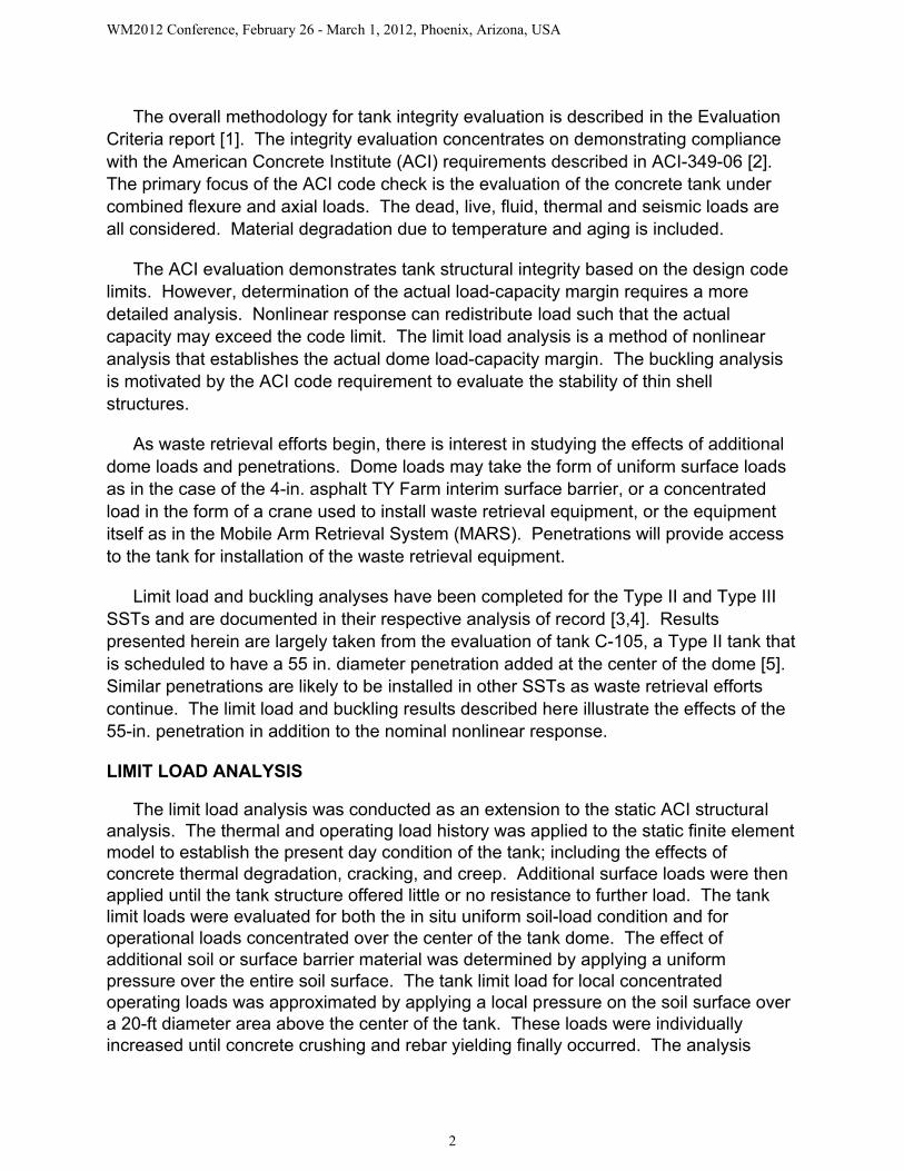
Table I summarizes the results of the limit load analysis. The penetration has a negligible effect on the uniform surface limit load. This is demonstrated in Figure 4, which shows that the load-displacement responses for the uniform surface load are essentially identical regardless of the presence of the penetration. The primary response for this loading is bending in the outer dome – haunch region, as shown in Figure 5 (exaggerated scale for clarity). This flattening of the dome and radial bulging of the wall is far removed from the penetration. The penetration accordingly has little effect on the response of the tank to the uniform surface load.
Table I. Summary of Limit Load Analyses
Geometry/Concrete
Limit Load - Uniform
(psi)
Limit Load - Local (kip)
Equiv Load -Uniform
(psi)Equiv Load -Local (kip)
Safety Factor
(uniform)*
Safety Factor (local)*
No Pen/Nom. 38 5300 6.35 531 6.98 10.98
Pen/Nom. 38 3300 6.31 491 7.02 7.72
No Pen/LB 33 4500 6.20 538 6.32 9.36
Pen/LB 33 2500 6.16 499 6.36 6.01
*Minimum Required Safety Factor = 3.0
WM2012 Conference, February 26 - March 1, 2012, Phoenix, Arizona, USA
6
Figure 4. Load-Displacement Response – Uniform Surface Load
Figure 5. Uniform Surface Load Tank Deformation (Scale Factor = 40)
In contrast, the penetration has a significant effect on the local limit load as shown in Figure 6. Figure 7 shows the tank deformation under the local load. The reverse bending of the dome at the center of the tank where the penetration will be added

WM2012 Conference, February 26 - March 1, 2012, Phoenix, Arizona, USA
7
suggests that the change in stiffness resulting from the penetration will have a significant effect. The penetration reduces the concentrated limit load by about 30% for the nominal concrete case.
Figure 6. Load-Displacement Response – Local Load
Figure 7. Local Load Tank Deformation (Scale Factor = 40)
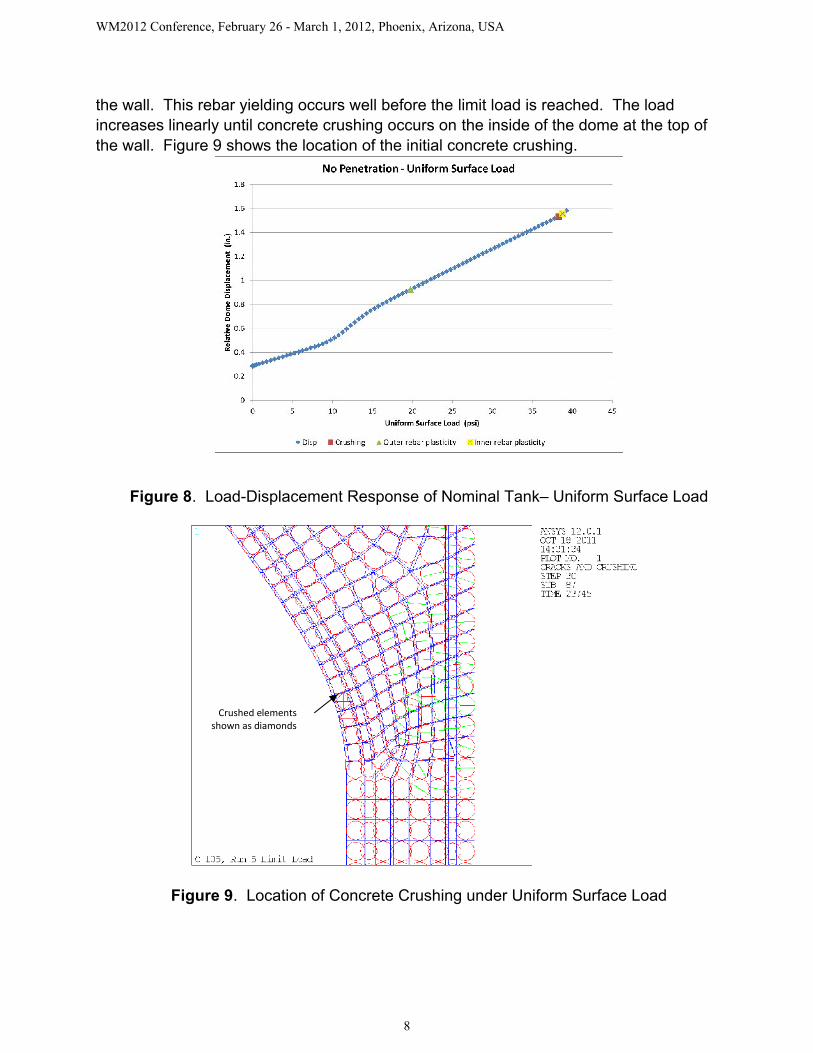
As noted above, the limit load is defined as the onset of both concrete crushing and yielding of the rebar. In the uniform surface loading case, Figure 8, the initial rebar yielding is in the form of tensile plastic strain in the outer meridional rebar at the top of
WM2012 Conference, February 26 - March 1, 2012, Phoenix, Arizona, USA
8
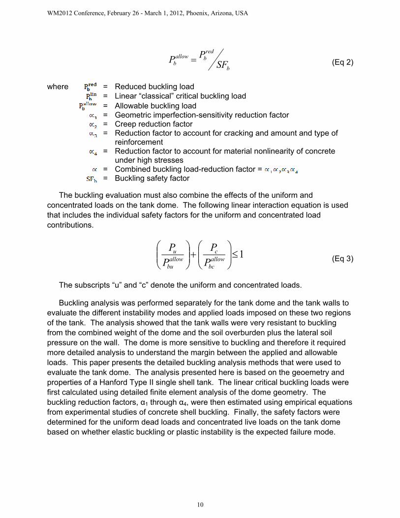
the wall. This rebar yielding occurs well before the limit load is reached. The load increases linearly until concrete crushing occurs on the inside of the dome at the top of the wall. Figure 9 shows the location of the initial concrete crushing.
Figure 8. Load-Displacement Response of Nominal Tank– Uniform Surface Load
Figure 9. Location of Concrete Crushing under Uniform Surface Load
Crushed elements shown as diamonds

WM2012 Conference, February 26 - March 1, 2012, Phoenix, Arizona, USA
9
In the local (concentrated) load case with the 55-in. penetration, the hoop rebar near the penetration yields in compression just prior to the onset of concrete crushing. For the nominal case (no penetration), the hoop rebar yields in compression after the onset of concrete crushing. For both local load cases, the load continues to increase after the initial crushing as shown in Figure 6, indicating the dome’s continuing ability to carry load, although with rapid decrease in stiffness. Figure 10 illustrates the progressive nature of the concrete crushing in the dome under the local loading.
Onset of Crushing at Lower Surface Crushing Progresses Through Thickness
Figure 10. Location of Concrete Crushing under Local Load (crushed elements shown as diamonds)
In conclusion, the limit load analysis establishes the load capacity of the tank based on the nonlinear analysis of the tank under increasing load. The effects of uniform surface loads and local concentrated loads were considered. The capacity of the tank under local concentrated loads is reduced by the presence of a large penetration at the center of the dome but is insensitive to uniform surface loads.
CONCRETE SHELL BUCKLING ANALYSIS
Chapter 19 of ACI 349-06 [2] requires the investigation of buckling instability for thin concrete shells, including the reduction in buckling capacity by large deflections, creep effects, temperature, cracking, and deviations between the actual and theoretical shell geometry. ACI 349-06 identifies ACI SP-67, Concrete Shell Buckling [7], as a source of approaches for determining the critical buckling loads of reinforced concrete shells. The following practical approach recommended by the International Association for Shell and Spatial Structures (IASS) Working Group No. 5, Recommendations for Reinforced Concrete Shells and Folded Plates, is described in ACI SP-67 [7].
linb
linb
redb PPP 4321 (Eq 1)
WM2012 Conference, February 26 - March 1, 2012, Phoenix, Arizona, USA
10
b
redballow
b SFPP (Eq 2)
where = Reduced buckling load= Linear “classical” critical buckling load= Allowable buckling load= Geometric imperfection-sensitivity reduction factor= Creep reduction factor= Reduction factor to account for cracking and amount and type of
reinforcement= Reduction factor to account for material nonlinearity of concrete
under high stresses= Combined buckling load-reduction factor = = Buckling safety factor
The buckling evaluation must also combine the effects of the uniform and concentrated loads on the tank dome. The following linear interaction equation is used that includes the individual safety factors for the uniform and concentrated load contributions.
1
allow
bc
callow
bu
u
P
P
P
P(Eq 3)
The subscripts “u” and “c” denote the uniform and concentrated loads.
Buckling analysis was performed separately for the tank dome and the tank walls to evaluate the different instability modes and applied loads imposed on these two regions of the tank. The analysis showed that the tank walls were very resistant to buckling from the combined weight of the dome and the soil overburden plus the lateral soil pressure on the wall. The dome is more sensitive to buckling and therefore it required more detailed analysis to understand the margin between the applied and allowable loads. This paper presents the detailed buckling analysis methods that were used to evaluate the tank dome. The analysis presented here is based on the geoemetry and properties of a Hanford Type II single shell tank. The linear critical buckling loads were first calculated using detailed finite element analysis of the dome geometry. The buckling reduction factors, α1 through α4, were then estimated using empirical equationsfrom experimental studies of concrete shell buckling. Finally, the safety factors were determined for the uniform dead loads and concentrated live loads on the tank dome based on whether elastic buckling or plastic instability is the expected failure mode.
WM2012 Conference, February 26 - March 1, 2012, Phoenix, Arizona, USA
11
Finite Element Critical Buckling Analysis
Finite element analysis can be used to accurately estimate the linear critical buckling load by simulating the geometric details of the tank geometry with its variable thickness, concrete elastic modulus, and the stiffening effect of the reinforcing bars. The finite element model can also be easily modified to investigate the effect of cutting a new penetration in the dome to facilitate waste retrieval. In comparison, the closest analytical approximation conservatively treats the tank as a thin spherical cap with clamped edges, constant thickness, and constant modulus.
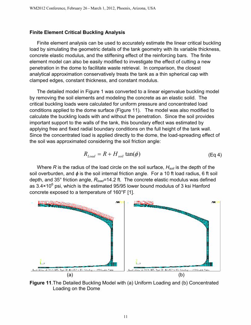
The detailed model in Figure 1 was converted to a linear eigenvalue buckling model by removing the soil elements and modeling the concrete as an elastic solid. The critical buckling loads were calculated for uniform pressure and concentrated load conditions applied to the dome surface (Figure 11). The model was also modified to calculate the buckling loads with and without the penetration. Since the soil provides important support to the walls of the tank, this boundary effect was estimated by applying free and fixed radial boundary conditions on the full height of the tank wall. Since the concentrated load is applied directly to the dome, the load-spreading effect of the soil was approximated considering the soil friction angle:
)tan(soilLoad HRR (Eq 4)
Where R is the radius of the load circle on the soil surface, Hsoil is the depth of the soil overburden, and ϕ is the soil internal friction angle. For a 10 ft load radius, 6 ft soil depth, and 35° friction angle, Rload=14.2 ft. The concrete elastic modulus was defined as 3.4×10⁶ psi, which is the estimated 95/95 lower bound modulus of 3 ksi Hanford concrete exposed to a temperature of 160°F [1].
(a) (b)
Figure 11.The Detailed Buckling Model with (a) Uniform Loading and (b) Concentrated Loading on the Dome
WM2012 Conference, February 26 - March 1, 2012, Phoenix, Arizona, USA
12
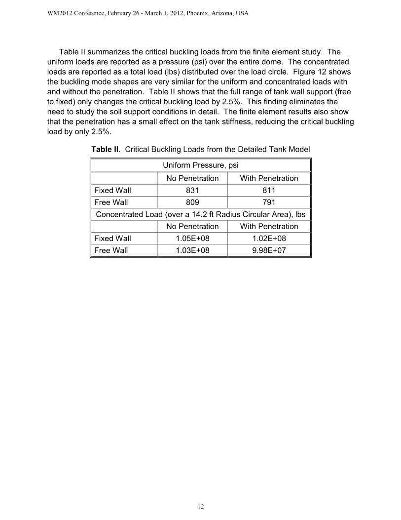
Table II summarizes the critical buckling loads from the finite element study. The uniform loads are reported as a pressure (psi) over the entire dome. The concentrated loads are reported as a total load (lbs) distributed over the load circle. Figure 12 shows the buckling mode shapes are very similar for the uniform and concentrated loads with and without the penetration. Table II shows that the full range of tank wall support (free to fixed) only changes the critical buckling load by 2.5%. This finding eliminates the need to study the soil support conditions in detail. The finite element results also show that the penetration has a small effect on the tank stiffness, reducing the critical buckling load by only 2.5%.
Table II. Critical Buckling Loads from the Detailed Tank Model
Uniform Pressure, psi
No Penetration With Penetration
Fixed Wall 831 811
Free Wall 809 791
Concentrated Load (over a 14.2 ft Radius Circular Area), lbs
No Penetration With Penetration
Fixed Wall 1.05E+08 1.02E+08
Free Wall 1.03E+08 9.98E+07

WM2012 Conference, February 26 - March 1, 2012, Phoenix, Arizona, USA
13
(a) (b)
(c) (d)
Figure 12.Buckling Mode Shapes for (a) Uniform Load Without the Penetration, (b) Uniform Load with the Penetration, (c) Concentrated Load Without the Penetration, and (d) Concentrated Load with the Penetration
Additional buckling calculations were performed with a 360° shell model of the Type-II tank dome to confirm the results in Table II and to investigate the potential for asymmetric buckling. The shell model was constructed following the mid-thicknessprofile of the tank dome and it includes the thickness variation from the center to the tangent point with the vertical wall. Table III reports the first and second mode eigenvalues (critical buckling loads) for the uniform and concentrated load conditions. Additional results are included where the load was offset 20 ft from the center to investigate if the dome was more or less susceptible to buckling compared to the centerloaded condition.
WM2012 Conference, February 26 - March 1, 2012, Phoenix, Arizona, USA
14
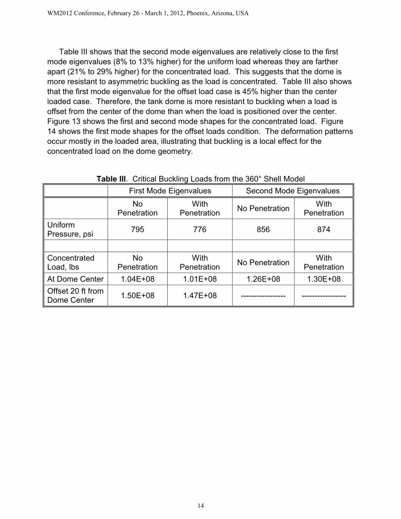
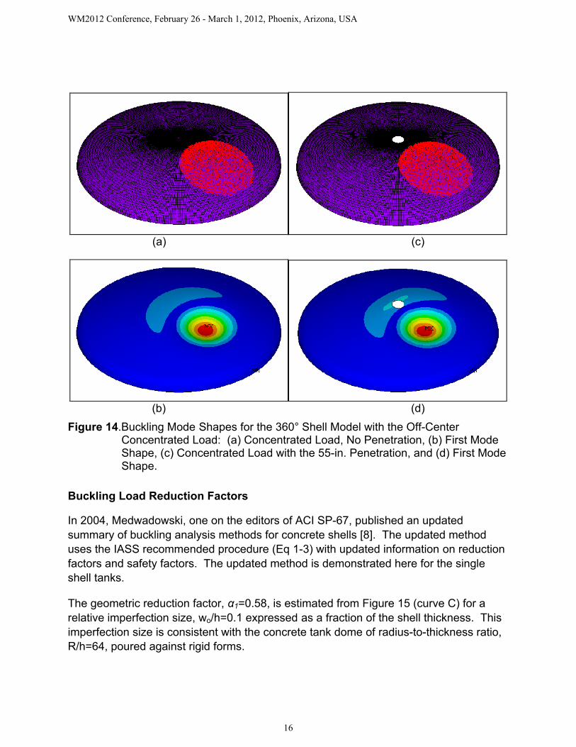
Table III shows that the second mode eigenvalues are relatively close to the first mode eigenvalues (8% to 13% higher) for the uniform load whereas they are farther apart (21% to 29% higher) for the concentrated load. This suggests that the dome is more resistant to asymmetric buckling as the load is concentrated. Table III also showsthat the first mode eigenvalue for the offset load case is 45% higher than the centerloaded case. Therefore, the tank dome is more resistant to buckling when a load is offset from the center of the dome than when the load is positioned over the center. Figure 13 shows the first and second mode shapes for the concentrated load. Figure 14 shows the first mode shapes for the offset loads condition. The deformation patterns occur mostly in the loaded area, illustrating that buckling is a local effect for the concentrated load on the dome geometry.
Table III. Critical Buckling Loads from the 360° Shell Model
First Mode Eigenvalues Second Mode Eigenvalues
No Penetration
With Penetration
No PenetrationWith
Penetration
Uniform Pressure, psi
795 776 856 874
Concentrated Load, lbs
No Penetration
With Penetration
No PenetrationWith
Penetration
At Dome Center 1.04E+08 1.01E+08 1.26E+08 1.30E+08
Offset 20 ft from Dome Center
1.50E+08 1.47E+08 ----------------- -----------------

WM2012 Conference, February 26 - March 1, 2012, Phoenix, Arizona, USA
15
(a) (d)
(b) (e)
(c) (f)
Figure 13. Buckling Mode Shapes for the 360° Shell Model: (a) Concentrated Load, No Penetration, (b) First Mode Shape, (c) Second Mode Shape, (d) Concentrated Load with the 55-in. Penetration, (e) First Mode Shape, and (f) Second Mode Shape.
WM2012 Conference, February 26 - March 1, 2012, Phoenix, Arizona, USA
16
(a) (c)
(b) (d)
Figure 14.Buckling Mode Shapes for the 360° Shell Model with the Off-Center Concentrated Load: (a) Concentrated Load, No Penetration, (b) First Mode Shape, (c) Concentrated Load with the 55-in. Penetration, and (d) First Mode Shape.
Buckling Load Reduction Factors
In 2004, Medwadowski, one on the editors of ACI SP-67, published an updated summary of buckling analysis methods for concrete shells [8]. The updated method uses the IASS recommended procedure (Eq 1-3) with updated information on reduction factors and safety factors. The updated method is demonstrated here for the single shell tanks.
The geometric reduction factor, α1=0.58, is estimated from Figure 15 (curve C) for a relative imperfection size, wo/h=0.1 expressed as a fraction of the shell thickness. This imperfection size is consistent with the concrete tank dome of radius-to-thickness ratio, R/h=64, poured against rigid forms.

WM2012 Conference, February 26 - March 1, 2012, Phoenix, Arizona, USA
17
Figure 15. Geometric Imperfection factor, α1.
The creep imperfection factor, α2, is calculated as: )log(25
12
cf (Eq 5)
Where fc is the concrete compressive strength at the time of loading measured in MPa. The estimated lower bound compressive strength of 31.7 MPa (4.6 ksi) gives α2=0.50.
The cracking and reinforcement factor, α3, is debated. Medwadowski [8] takes the position that prior to buckling the stresses in at least one direction (i.e., radial for the tank dome) will be compressive and cracking would not tend to reduce the shell stiffness in that direction. Tension in the other direction (i.e., hoop tension in the outer perimeter of the dome) would also tend to decrease the danger of buckling. Based on these observations Medwadowski proposed a value of α3=1.0. Based on the dome concrete properties and steel reinforcements, other estimates give α3=0.92, which is similar.
The plasticity reduction factor, α4, accounts for the nonlinear deformation of concrete when loaded to near its crushing strength. The equations for α4 are based on empirical evidence and Medwadowski recommends using the full quadratic form that condenses to the following equation.
2
3
4
1
1
ultP
P (Eq 6)
Where linbPP 3213 and Pult is the ultimate limit load.

WM2012 Conference, February 26 - March 1, 2012, Phoenix, Arizona, USA
18
Buckling Safety Factors
Medwadowski [8] provides guidance on defining safety factors that account for bucklingsensitivity to imperfections and whether elastic buckling or plastic instability is the expected failure mode. The safety factor is based on material failure when the critical buckling load times the geometric imperfection factor is greater than two times the ultimate limit load. In that case the structure would reach limit load failure before it buckled. Table IV summarizes the recommended safety factors.
Table IV. Buckling Safety Factors Recommended by Medwadowski [8]Structural Behavior Safety Factor, SF
Shells that are not sensitive to imperfections 1.75
All other shells:
Plastic Instability: ultlinb PP 21 1.75
Buckling Instability: ultlinb PP 21
h
wo
eSF5.1
5.2
For the single shell tank domes, ultlinb PP 101 for both uniform and concentrated loads.
Therefore, plastic instability would occur before buckling and a safety factor of 1.75 is appropriate.
Dome Buckling Evaluation
Table V summarizes the buckling analysis of the tank dome with and without a center penetration. The uniform pressure load corresponds to 6 ft of soil overburden at the dome center. The concentrated load is 400 kips distributed over a 10 ft radius area at the soil surface. These loading conditions are consistent with the limit load analysis described in this paper.
It is interesting to note that the combined effect of factors α1 through α4 reduces the buckling loads to about 5% of the linear critical buckling loads. This illustrates that the theoretical buckling loads must be reduced very significantly to account for the geometric defects and material property uncertainties present in reinforced concrete shells. A further margin of safety is then applied by dividing the reduced buckling loads by the 1.75 safety factors to calculate the allowable load capacity. Table V shows that for this particular loading example, the combined demand to capacity ratios for the tank dome are 0.61 without the penetration and 0.71 with the penetration. This demonstrates how the buckling analysis method can be used to assess the safety of tank loading conditions that may be applied during waste retrieval activities.

WM2012 Conference, February 26 - March 1, 2012, Phoenix, Arizona, USA
19
Table V. Summary of Dome Buckling Analysis
ItemTank Without the
PenetrationTank With the Penetration
Maximum Dome Temperature, Tmax, °F 160 160
Overburden Depth, ft 6.0 6.0
Soil Density, lb/ft3 125 125
Concrete Compressive Strength, fc, psi 4600 4600
Concrete elastic modulus at Tmax, 106 psi 3.4 3.4
Concrete Poisson’s ratio at Tmax 0.15 0.15
Concrete density, lb/ft3 145 145
Steel elastic modulus at Toper = 80°F, 106 psi 29.4 29.4
Steel Poisson’s ratio at Toper = 80°F 0.30 0.30
Unfactored critical uniform dome pressure, Pc, psi 809 791
α1, geometric reduction factor 0.58 0.58
α2, creep reduction factor 0.5 0.5
α3, cracking reduction factor 1.0 1.0
α4, nonlinear material reduction factor 0.164 0.168
Reduced uniform dome load, P4 = α1α2α3α4Pc, psi 38.7 38.6
Unfactored critical concentrated dome load, Pc, lb 103 × 106 99.8 × 10⁶
α1, geometric reduction factor 0.58 0.58
α2, creep reduction factor (creep model/SP-67) 0.50 0.50
α3, cracking reduction factor 1.0 1.0
α4, nonlinear material reduction factor 0.166 0.103
Reduced concentrated dome load, P4 = α1α2α3α4Pc, lb
4.97 × 10⁶ 2.98 × 10⁶
Finite Element Limit Loads
Total uniform limit load, psi 39.2 39.16
Total concentrated limit load, kip 5038 2999
Applied Pressure on Dome, psi 10.44 10.44
Applied Concentrated Dome Load, kip 400 400
Safety Factors, Uniform / Concentrated Loads 1.75 / 1.75 1.75 / 1.75
Combined Demand/Capacity,Uniform + Concentrated Loads
0.61 0.71
WM2012 Conference, February 26 - March 1, 2012, Phoenix, Arizona, USA
20
CONCLUSIONS
This paper summarizes the structural analysis methods that were used to evaluate the limit load and buckling limit states of the underground single shell tanks at the Hanford site. The limit loads were calculated using nonlinear finite element models that capture the progressive deformation and damage to the concrete as it approaches the limit load. Both uniform and concentrated loads over the tank dome were considered,and the analysis shows how adding a penetration in the center of the tank would affect the limit loads. For uniform surface loads, the penetration does not affect the limit load because concrete crushing and rebar yielding initiates first at the top of the wall, away from the penetration. For concentrated loads, crushing initiates at the center of the dome, so the penetration does reduce the concentrated limit load somewhat. However, the safety factors comparing the limit loads to the maximum allowable applied loads remain well above the required value of 3.0.
The buckling analysis method accounts for the geometric imperfections, concrete creep, cracking and reinforcements, and concrete plasticity in determining the allowable buckling load limits. The method was demonstrated in this paper for the evaluation of a tank before and after a penetration is added in the dome center. Finite element buckling models were used to accurately calculate the linear critical buckling loads. The models showed that adding the penetration reduces the linear critical buckling load by only 2.5%. Bounding cases also showed that the possible range of soil support on the walls does not significantly affect the dome buckling loads. Buckling models of the full 360° dome also showed that the dome is more resistant to buckling when the load is offset than when it is positioned over the center. These limit load and buckling analysis methods are being used at the Hanford site to assess the tank loads that can be safelyapplied during future waste retrieval activities.
ACKNOWLEDGEMENT
The authors would like to acknowledge the management support of Washington River Protection Solutions and the funding provided on behalf of the U.S. Department of Energy, Office of River Protection to perform the Single Shell Tank Analysis of Record Project.
REFERENCES
1. Johnson KI, JE Deibler, FG Abatt, and MW Rinker. 2010. Single-Shell Tank Structural Evaluation Criteria. RPP-46442, Rev. 0, Pacific Northwest National Laboratory, Richland, Washington.

WM2012 Conference, February 26 - March 1, 2012, Phoenix, Arizona, USA
21
2. ACI. 2007. American Concrete Institute Code Requirements for Nuclear Safety Related Concrete Structures. ACI 349-06, American Concrete Institute, Farmington Hills, Michigan.
3. Rinker MW, KI Johnson, SK Bapanapalli, NK Karri, JE Deibler, SP Pilli, CE Guzman-Leong, SE Sanborn, FG Abatt, JA Dewberry, BM Larsen, KL Stoops, and LJ Julyk. 2011. Single-Shell Tank Integrity Project Analysis of Record: Hanford Type II Single-Shell Tank Thermal and Operating Loads and Seismic Analysis. RPP-RPT-49989, Rev. 0, Pacific Northwest National Laboratory, Richland, Washington.
4. Rinker MW, KI Johnson, SK Bapanapalli, NK Karri, JE Deibler, SP Pilli, CE Guzman-Leong, SE Sanborn, FG Abatt, JA Dewberry, BM Larsen, KL Stoops, and LJ Julyk. 2011. Single-Shell Tank Integrity Project Analysis of Record: Hanford Type III Single-Shell Tank Thermal and Operating Loads and Seismic Analysis. RPP-RPT-49990, Rev. 0, Pacific Northwest National Laboratory, Richland, Washington.
5. Rinker MW, SK Bapanapalli, JE Deibler, CE Guzman-Leong, FG Abatt, BM Larsen, LJ Julyk, KI Johnson, NK Karri, SP Pilli, SE Sanborn, JA Dewberry, and KL Stoops. 2011. Single-Shell Tanks Large Riser Evaluation: An Evaluation of Single-Shell Tank 241-C-105 for the Addition of a Large Penetration in the Tank Dome. RPP-CALC-51195, Rev. 0, Pacific Northwest National Laboratory, Richland, Washington.
6. ANSYS®. 2011. ANSYS® Mechanical, Release 12. ANSYS Inc., Canonsburg, Pennsylvania.
7. ACI. 1981. Concrete Shell Buckling. ACI SP-67, EP Popov and SI Medwadowski (ed.), American Concrete Institute, Detroit, Michigan.
8. Medwadowski SJ. 2004. “Buckling of Concrete Shells: An Overview.” Journal of the International Association for Shell and Spatial Structures 2004, No. 144 pp. 51–63.


![Advances in Shell Buckling: Theory and Experimentsucess21/[214] Advances, shells...Advances in Shell Buckling: Theory and Experiments reasonably self-contained, I present in Secs](https://img.dokumen.tips/doc/110x75/5e9188f5900cb303c8385212/advances-in-shell-buckling-theory-and-experiments-ucess21214-advances-shells.jpg)


![Advances in Shell Buckling: Theory and Experimentsucess21/[214] Advances, shells IJBC 2015 [e-pub].pdf · January 23, 2015 14:36 WSPC/S0218-1274 1530001 Advances in Shell Buckling:](https://img.dokumen.tips/doc/110x75/5ab30c3f7f8b9a6b468e0b03/advances-in-shell-buckling-theory-and-ucess21214-advances-shells-ijbc-2015.jpg)