Embed Size (px)
Citation preview

1
LIGHTNING PROTECTION FOR CRITICAL EXPLOSIVES OPERATIONS
Mitchell Guthrie, Independent Engineering Consultant, 234 Guthrie Road, Blanch, NC 27212 USA, 336 694 6177, 336 694 5224, [email protected] Alain Rousseau, SEFTIM, 49 Rue de la Bienfaisance F-94300 Vincennes France,33-143281043, 33-143654337, [email protected] Abstract: Guthrie and Rousseau (2006) provided a discussion on the use of IEC 62305 standards for the protection of explosives storage facilities. This paper builds on that discussion and examines a practical case involving lightning protection system design for a process which includes a structure containing both a hazardous (classified) location and a critical process that requires a highly reliable service such as electrical power, water supply, etc.; characteristic of, for example, an explosives mixing or demil operation. For such applications, the protection level required could exceed the normal lightning protection level specified by existing standards due to sensitivity to internal arcing and the high level of reliability required of the critical service. The risk assessment must consider the entire range of operations conducted at the facility as well as the entire range of threats due to lightning, regardless of the probability of the threat. The first step is to perform a statistical analysis as per IEC 62305-2. This method analyzes in detail the structure, the operation, the incoming and outgoing lines (services) and, based on a probabilistic calculation, provides a risk level. The risk level then defines a protection scheme. However the most severe risk level may not be adequate to provide the protection level required for the application. Where protection greater than LPL I is required, we must then examine all lines that penetrate the facility walls, including sirens, process control lines, and instrumentation. Next we will need to review the potential equalization provided internal to the process and ensure that all sources of internal arcing are addressed. Finally, all critical parts of the process must be examined to address the mitigation of all possible threat scenarios.
1 Introduction
Protection against lightning for structures dealing with the processing of explosives devices aged beyond their service life can be quite complex. There are several phases in the process and each of them requires specific attention. In this paper, we will address three stages: (1) storage of the material awaiting processing; (2) processing of the material; and (3) treatment of waste. There may be a significant length of time between the arrival of the devices at the site and the start of the process. Structures associated explosives storage generally reflect a high level of risk of physical damage in lightning risk assessments due to the high concentration of explosives
Thirty-Third United States Department of Defense
Explosives Safety Seminar
2
material over a significant period of time. The second stage involves the processing of the device where the explosives or chemical materials are removed. At this stage the risk of physical damage is reduced because there is a lower amount of explosives involved in the structure but there is greater human exposure and at therefore the human risk needs to be considered. The final stage to be considered in this example is the final treatment made to be able to deal with each part and component in a regular waste chain. At this stage, the main threat is linked to the process. In some cases the continuity of the process is crucial to safety. This paper will work through an example that will address the three stages discussed above. The basic tool will be the IEC 62305-2 [1] lightning risk assessment standard but as we will see it is very often necessary to address more than that to obtain a viable protection system at a limited cost.
2 Structures under consideration The following sections provide a description of the construction of the structures used in this example along with an indication of the exposure of personnel associated with each structure. The structures are located in an area of low to moderate lightning activity. In this example we will assume a ground strike density, Ng, of 2 strikes/year/km².
2.1 Storage facility Guthrie and Rousseau [2] addressed the protection of a reinforced-concrete earth covered magazine. Conclusions of that paper were that quite often a lightning protection level more stringent than lightning protection level (LPL) I (the most stringent lightning protection level addressed in IEC 62305 [3] [4]) will be required to reduce the applicable risk below the tolerable level. Acceptable protection techniques to reduce the risk include masts, overhead ground wires, and integral systems [5]. For NATO applications, IEC 62305-3 will also allow the use of a mesh-type system. Another option available, if the facility is able to withstand a direct strike, is to use the structure itself as a natural lightning protection (as per a Faraday-type system). In some cases, regulations may allow the use of the rebar in steel reinforced concrete structures to serve as the strike termination component and down conductors. If there is concern over damage to the roof of the structure caused by a direct strike, for example resulting in leaks, one possible method available to the user of IEC 62305-3 [3] is the installation of a mesh-type lightning protection system. The spacing of the mesh will be dependent upon the selected lightning protection level. In United States national lightning protection standards such as NFPA 780 [6] and UL 96A [7], the mesh-type strike termination system is not specifically recognized as an acceptable method. In this exercise, we will select a different type of construction for the storage structure. The storage facility will consist of a steel frame with 5 meter spacing, masonry (concrete block) walls (without reinforcing steel), and a thin corrugated metallic outer surface. The structure will be 20 meters long by 10 meters wide with a height of 5 meters. There are no services connected to the structure. The metal frame of the structure is sufficient in size to withstand a direct strike and each part of the frame is connected to the others by large bolts with significant surface area contact. Some
3
may consider the frame to provide a natural lightning protection system (both strike termination and down conductors) as long as consideration is given to sparks and molten metal that may result from the impact of the strike to the metal (either the metal frame or the corrugated covering). United States lightning protection standards [6] [7] do not allow the exterior of a structure to serve as a “natural” strike termination device if it is less than 4.8 mm (3/16-inch) thick. There are no personnel normally present in the storage area. However, there is transient exposure of personnel associated with the transfer of material in and out of the storage facility as well as maintenance personnel performing such functions as vegetation control. The total estimated exposure of personnel to the site is determined to be 1500 hours per year. The risk of explosion needs to be addressed due to the large amount of solid explosive materials. In this case, the environment hazard is not considered as all the other structures at the site and adjacent to the facility are far enough away (although an explosion may result in some windows breaking in the closest structures)
2.2 Processing facility In this example, the structure also utilizes a metallic frame with masonry (concrete block) walls and a corrugated sheet metal exterior. This structure is 40 meters long, 10 meters wide and a height of 7 meters. The spacing between the steel frame members is 10 meters. As with the storage facility, the metal frame of the structure is sufficient in size to withstand a direct strike and each part of the frame is connected to the others by large bolts and significant surface area contact. While some may consider the frame of the structure to provide “natural” lightning protection, United States lightning protection standards [6] [7] do not allow the exterior of a structure to serve as a “natural” strike termination device if it is less than 4.8 mm (3/16-inch) thick. The magnetic field induced in the structure by a direct strike or a strike near the structure needs to be considered. The services connected to the structure are numerous:
• Water : in plastic pipe
• Compressed air : in plastic pipe
• Power: underground cable, connected to another building 600 meters away (L 9m x W 3m x H 3m)
• Telecom: one line, underground, connected to the same building as the power line (600 m away)
• Antenna: on roof.
• External lighting system: fed from the primary distribution panel of the structure
• Warning siren: connected to the primary distribution panel of the structure
• Remote control data line: connected to a small cabinet inside the structure
• Data line: connected to security fence.
4
Over the period of a year, it is estimated that 2 people are present 8 hours a day for a total duration of 3900 hours. The risk of explosion needs to be considered due to the small number of devices present before they are processed. Of course, volume of explosive material is much lower than for the storage facility.
2.3 Final treatment facility This structure is also metallic framed but with brick walls covered by corrugated sheet metal. The dimensions of the structure are 45 meters in length by 20 meters in width and a 8 meter height. The spacing between the steel frame members is 10 meters. As with the other facilities, the metal frame of the structure is sufficient in size to withstand a direct strike and each part of the frame is connected to the others by large bolts and significant surface area contact. While some may consider the frame of the structure to provide “natural” lightning protection, United States lightning protection standards [6] [7] do not allow the exterior of a structure to serve as a “natural” strike termination device if it is less than 4.8 mm (3/16-inch) thick. In this case, the risk of an explosion is minimized due to the low concentration of explosives material but there are other hazards associated with the reliability of the process. The services connected to the structure are numerous:
• Water : in plastic pipe
• Gas : in metal pipe
• Compressed air : in plastic pipe
• Power: underground cable, connected to another building 120 meters away (L 9m x W 3m x H 3m).
• Telecom: one underground line, connected to the same building as the power line (120 m away).
• Sprinkler system: metal pipe
• Antenna: on roof.
• External lighting system: fed from the primary distribution panel of the structure
• Warning siren: connected to the primary distribution panel of the structure
• Remote control data line: connected to a small cabinet inside the structure
There are 3 people normally present for a total duration estimated to be 1600 hours per year.

5
3 Risk assessment IEC 62305-2 [1] breaks the overall risk into four primary loss categories. These categories are: the risk of loss or injury to humans (R1), the risk of loss of the service to the public (R2), the risk of loss of cultural heritage (R3), and the risk of economic loss (R4). The risk of loss of human life, the loss of the structure, the loss of assets stored in the structure, as well as the effect on the ability of the organization to perform their intended function must be assessed. Risk category R1 adequately covers the risk of loss or injury to humans. It is generally accepted that the risk of economic loss, R4, is not a primary factor in the assessment of protection of explosives facilities. Safety must always take priority over cost where injury to humans and loss of critical assets are involved. When considering the risk of economic loss associated with the protection of explosives facilities there are numerous costs that are not normally valid for ordinary structures. In addition to the costs associated with the loss of the structure, assets contained in the structure, and costs resulting from human injury. The cost of explosives incident investigation and the associated public relations effort to ensure the local community and their elected representatives that the operations being conducted near their homes, schools, or offices are safe and they are not in danger. These costs will generally be much more than the cost of the installation and maintenance of a lightning protection system, depending upon the expected damage. In addition, there are discussions in IEC committees to try to refine the economic loss calculation as there are some drawbacks with this method [8]. There is normally a problem in getting the necessary data to estimate the cost of an incident investigation and associated public relations effort but there are generally procedures to estimate the cost of replacement of the structure and cost of the lightning protection system installation. Each of the primary risk categories is calculated by summing relevant risk components. The risk components are related to the loss (injury to humans, physical damage to the structure, and failure of internal systems) and the source of the threat (direct strike to the structure, flash near the structure, direct strike to a service connected to the structure and flash near a service connected to the structure). For example, risk component RA is associated with the risk of injury to humans due to a direct strike to the structure (touch and step voltages) while RU is the component related to injury to humans caused by touch voltage inside the structure due to lightning current injected into a line entering the structure. Each risk component is a product of the number of lightning events on the structure, the probability that the event will result in damage, and the extent of the damage. The number of lightning events, N, depends primarily on the dimensions of the structure and the average number of strikes to ground per year per square kilometer, Ng, in the area. The probability of damage, P, depends on the protection means provided (whether inherent in the construction of the structure or intentionally provided. The consequence of the loss, L, is a function of the use of the structure and its contents, the exposure of humans during lightning events, the value of the goods affected by the damage and the measures provided to limit the amount of loss. In the risk of injury to humans, the most important parameters under consideration in the consequence of the loss are the number of people exposed to the danger and
6
the length of exposure. The exposure of personnel can be limited greatly by the incorporation of lightning warning techniques into explosives handling Standard Operating Procedures (SOP). It must be stressed that no matter what lightning warning system technology is used, the efficiency will never be 100 percent so there will always be a finite probability of exposure of personnel to the probability of a first strike. Calculations have been performed using a commercially available software implementation IEC 62305-2 (Jupiter software Version 1.3 [9]).
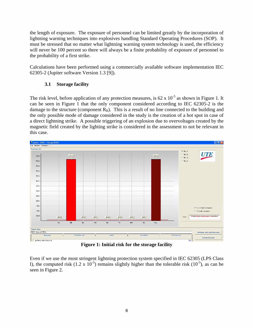
3.1 Storage facility The risk level, before application of any protection measures, is 62 x 10-5 as shown in Figure 1. It can be seen in Figure 1 that the only component considered according to IEC 62305-2 is the damage to the structure (component RB). This is a result of no line connected to the building and the only possible mode of damage considered in the study is the creation of a hot spot in case of a direct lightning strike. A possible triggering of an explosion due to overvoltages created by the magnetic field created by the lighting strike is considered in the assessment to not be relevant in this case.
Figure 1: Initial risk for the storage facility
Even if we use the most stringent lightning protection system specified in IEC 62305 (LPS Class I), the computed risk (1.2 x 10⁻⁵) remains slightly higher than the tolerable risk (10-5), as can be seen in Figure 2.

7
Figure 2: Risk for the storage facility when LPS Class I is installed
One must now determine the best method to reduce the computed risk. Since the calculation was made considering the installation of an LPS Class I lightning protection system, we will need to find other ways to reduce the threat. Even though there is no personnel normally present, the duration of the exposure of transient personnel is quite high as there are many people coming in or close to the facility quite often. A possible solution in this case would be to implement a lightning warning system into the SOP to minimize the exposure of personnel in the magazine area during thunderstorms. Lightning warning system have a finite efficiency which must be taken into account. The least expensive warning systems are based on the processing of the magnetic field emitted by lightning strikes. More expensive ones are based on the processing of the electrostatic field. Efficiencies considered generally range between 50 % and 90 % depending on the technology and the brand. In this case we will assume a lightning warning system is used which provides a 50% warning efficiency. If the system was 100% efficient, the remaining risk would be eliminated as it would be possible to eliminate personnel exposure in the storage area or its surroundings in case of lightning. Using an efficiency of only 50%, the risk remains but the duration is reduced by 50% of 1500 hours or 750 hours. As shown in Figure 3, a lightning protection system of LPL I used in conjunction with a lightning warning system with an efficiency of 50% will reduce the risk to a value below the tolerable risk (0.62 x10⁻⁵).

8
Figure 3: Final risk for the storage facility after implementation of a Class I LPS with a lightning warning system
As the metal frame forms a mesh of 5 meter spacing and as this is the dimensions requested by the standard for a LPS Class I protection system, there no need to implement a specific protection system provided that the metal frame meets the requirements for natural components, a suitable earthing system is used to provide grounding of the metal frame, and the required potential equalization techniques are implemented. Again, it must be stressed that United States lightning protection standards do not recognize the mesh system so an approved lightning protection system would have to be installed if this facility were located in the US.
3.2 Processing facility We will assume that only one of the two people present in the building will be in danger when the damage occurs due to surges along the lines (either from a direct strike to the building leading to big overvoltages on the connected lines or coming from a strike to these lines some distance from the building) and that both of them are in danger when exposed to a direct strike to the building. Based on these assumptions, the risk level before application of any protection measures is 14 x 10-3. If we consider that the storage facility studies led to the conclusion that a lightning warning system (LWS) is necessary, it is possible that the LWS can also reduce the exposure in this facility. The main danger in this structure occurs when people are manipulating the explosives devices. If we calculate the risk again based on this new level of exposure (50% of 3900 hours or 1950 hours), it reduces the resulting risk to 70 x 10-4 (see Figure 4). The main component of the risk is the damage to the structure due to incoming lines (component RV) and to a lesser extent direct damage to the building (RB) and damage due to overvoltages generated by a direct strike to the structure (Rc). A possible triggering of an explosion due to

9
overvoltages created by the lighting strike’s magnetic field is not considered relevant in this case, due to the way the explosives devices are processed.
Figure 4: Initial risk for the processing facility
To reduce the risk in this facility, we will need to:
- use the best available lightning protection system (LPS Class I with a mesh spacing of 5 m x 5 m) on the roof
- use also the natural elements of the building as down conductors spaced every 10 meters in accordance with IEC 62305-3, for a LPS Class I system
- protect the power and telecom lines with a coordinated set of surge protective devices (SPDs) in accordance with IEC 61643 [10] [11]. This will require Type 1 SPDs to handle a portion of the lightning current at the entrance of the lines (located in the main panel board for the power SPD and in at the telecom frame for the telecom line) and Type 2 SPDs to manage the overvoltages near the sensitive equipment (in our case, these Type 2 SPDs will be located in one or more subsidiary panel) supplying the equipment used for the process. It is imperative that the Type 2 and Type 1 SPDs used in the installation be coordinated together.
- install SPDs at the point of entry of the building for the antenna located on the roof, on the cable supplying the external lighting system, on the cable connected to the warning siren, on the data line connected to a small cabinet outside of the building and to the data line connected to the fence. These SPDs need to be Type 1 SPDs to provide equipotential bonding function but if the equipment need to be operational after the surge, Type 1+2 SPDs should be used in place of the Type 1 devices.

10
Figure 5: Risk for the processing facility when LPS Class I + SPDs are implemented
3.3 Final treatment facility
The total risk level, before application of any protection measures, is shown in Figure 6 to be 4.1 x 10⁻⁵. The primary components driving this risk are the damage to the structure due to a direct strike to the structure (component RB) and to the incoming lines (component RV).
Figure 6: Initial risk for the final treatment facility

11
To reduce the risk we may consider implementing a LPS Class IV (the least stringent of all LPS Classes in the standard) and we can obtain a risk level of 61 x 10-7 (which is below the tolerable risk). This also identifies that a Type 1 SPD based on a current withstand compatible with an LPS Class IV must be installed on the incoming lines.
Figure 7: Risk for the final treatment facility when LPS Class IV is implemented
4 Lightning protection based on possible damage scenarios
As shown in the previous sections, the risk assessment is a powerful tool to define what needs to be protected and at which level of protection. The possibility of taking care of additional measures such as SPDs in front of sensitive equipment or the use of a lightning warning system is also a benefit of the method. A limitation of the risk assessment method is that it describes the structure and the connected lines in what we could call a macroscopic view. Additional items such as antennas connected to the roof or external lighting systems cannot be characterized as incoming lines in this method due to their short length and specific layout. When we apply a closer view, we may also need to define protection for these items. These additional items are taken into account by the method and resulting need for protection, once it is determined that an LPS Class I protection system is found to be unable to reduce the risk to a tolerable level. When a Class I LPS or better is needed to reduce the risk, it is easy to integrate these additional items in the protection plan with the same level of protection even if they are not directly taken into account by the method. It may not always be necessary to protect these additional items. The situation is more difficult when the building appears to be self protected and needs no additional protection other than the natural lightning protection inherent in construction. In such
12
a case, the only method to determine what needs to be protected is a deterministic method. This method is based on establishing scenarios. Establishing scenarios dedicated to a specific building is also the solution to the second case where a Class I LPS is sufficient to provide protection and where protection of additional items may not be necessary. There are already some scenarios included in the risk assessment method: direct strike to the building leading to people injury, direct strike to the building leading to fire, induced strike on line leading to damage to electrical equipment and so on. But they are general scenarios and sometimes some specific scenarios need to be addressed. Let’s try to illustrate this with our examples. As far as the storage facility is concerned, the “basic” scenarios apply very well. However, one question can be raised: what will happen when a direct lightning will strike the structure if we use only the natural lightning protection system. The roof is made of metal sheets 1.5 mm thick which is not sufficient to avoid puncture. In the case of a lightning event, this will lead to sparks (between two sheets) or to molten metal dropping from the roof. A safety distance is then needed between the roof and the storage to ensure that these events will not trigger a fire and/or an explosion. This will require that the storage needs to be limited in height. IEC 62305-3 and all applicable US military standards also define separation distances in order to avoid sparkover between the lightning protection system and any grounded metal part in the vicinity. Regarding, the processing facility, part of the process which needs to be addressed is the device machining and possible surges occurring on the machine which can trigger a spark to the explosive device. This can be avoided by the installation of SPDs located on the supply of the machines used for processing the explosive device. The final stage of the process, waste treatment, seems to need no specific attention. The risk at this location is primarily a fire risk as the explosive material is not present anymore. Fire is very well addressed in the risk assessment so why should be need to establish some scenarios? We can provide one example to show that establishing scenarios is very important. If the process involved the presence of phosphorous, the material must be immersed in water at all times. Otherwise, exposure to air will cause a significant fires that is difficult to extinguish. Two scenarios can be then established. In the first one, a surge may damage some process control hardware which can, due to false order, open a water valve and let the water escape from the pipes when the process is running, leading ultimately to a fire at one or more places. This can be addressed by the installation of additional SPDs on the front of the process control equipment power supply, which the risk assessment hadn’t taken into account. The second scenario could be for a sparking between two metal parts (either between the metal frame of the building and metal part of the process or between two metal part of the process) leading to a water leakage. Protection means for that scenario are not easy to establish. First of all, one must check to see if the separation distance criterion is met between the internal structure of the process and the metal frame of the building. If not, equipotential bonding is needed between these parts at various places to ensure that no damaging spark will occur and especially at joint between two elements of the water pipes. Global bonding will be the rule in such a case.

13
5 Conclusions and recommendations
Lightning protection measures for an explosives storage structure is always a challenge. The first step in designing an efficient lightning protection system is to assess the risk in accordance with IEC 62305-2. The method leads to an evaluation of the risk parameters and protection measures required to decrease the calculated risk below the tolerable risk defined in the standard or set by the authority having jurisdiction. The risk assessment method detailed in IEC 62305-2 will provide a technique by which it can be determined whether the design should be compliant with a level of protection LPL I and LPL IV, or even better than LPL I. The IEC risk assessment can also identify those cases where measures above and beyond the installation of a lightning protection system may be required. An example is the use of a lightning warning system to reduce the exposure of personnel as a method to reduce the risk of injury to humans. The IEC 62305-2 risk assessment defines guidance for the lightning protection system needed to provide protection of the structure and to some extent internal electrical equipment. However, it does not address special scenarios. In the case of sensitive facilities or operations, it is often necessary to establish some scenarios to identify which part of the process need specific attention. This may lead for example to installation of additional SPDs to protect sensitive equipment or part of the process or to global equipotential bonding. It appears that in many cases, the definition of possible scenarios is as fundamental as the risk assessment and that such a combined approach will lead to the optimum protection for a specific structure. References 1. IEC 62305-2:2006, “Protection against lightning – Part 2: Risk management,” First Edition, International Electrotechnical Commission, Geneva, January 2006. 2. Guthrie Mitchell, Rousseau Alain, “A discussion on the use of IEC 62305 lightning protection standards for the protection of NATO explosives storage structures” Paper 9C, Thirty-Second United States Department of Defense Explosives Safety Seminar, August 2006. 3. IEC 62305-3:2006, “Protection against lightning – Part 3: Physical damage to structures and life hazard,” First Edition, International Electrotechnical Commission, Geneva, January 2006. 4. IEC 62305-1:2006, “Protection against lightning – Part 1: General principles,” First Edition, International Electrotechnical Commission, Geneva, January 2006. 5. DoD 6055.9-STD, “Ammunition and Explosives Safety Standards,” Chapter 7, Department of Defense, Washington, DC, 5 October 2004. 6. NFPA 780, “Standard for the Installation of Lightning Protection Systems,” National Fire Protection Association, Quincy, MA, 5 August 2004. 7. UL 96A, “UL Standard for Safety for Installation Requirements for Lightning Protection Systems,” 11th Edition, Underwriters Laboratories, Northbrook, IL, 26 July 2001. 8. Rousseau Alain, Gruet Pierre, “Practical approach for economic lightning risk evaluation”, Paper 8-12, International Lightning Protection Conference 2008 9. Jupiter; lightning risk assessment software developed by UTE (www.ute-fr.com)

14
10. IEC 61643-21, “Low voltage surge protective devices – Part 21: Surge protective devices connected to telecommunications and signaling networks – Performance requirements and test methods,” Edition 1.0, International Electrotechnical Commission, Geneva, 29 August 2000. 11. IEC 61643-1, “Low voltage surge protective devices – Part 1: Surge protective devices connected to low-voltage power distribution systems – Requirements and tests,” Edition 2.0, Amendment 2, International Electrotechnical Commission, Geneva, 30 March 2005. 12. IEC 62305-4:2006, “Protection against lightning – Part 4: Electrical and electronic systems within structures,” First Edition, International Electrotechnical Commission, Geneva, January 2006.