Embed Size (px)
Citation preview

lighting, electrics &communicationsL IGHTING , ELECTR ICS & COMMUNICAT IONS OVERV IEW . . . . 1 3 7
L IGHTING BAS ICS . . . . . . . . . . . . . . . . . . . . . . . . . . . . . . . . . 1 3 8
STORAGE /L IGHTING COMPAT IB I L ITY CHART . . . . . . . . . . . . . 1 3 9
CE IL ING FEED BAS ICS . . . . . . . . . . . . . . . . . . . . . . . . . . . . . . 1 4 0
PLANNING WITH CE IL ING FEED . . . . . . . . . . . . . . . . . . . . . . 1 4 1
BASE FEED BAS ICS . . . . . . . . . . . . . . . . . . . . . . . . . . . . . . . . . 1 4 2
POWER D I STR IBUT ION BAS ICS . . . . . . . . . . . . . . . . . . . . . . . . 1 4 3
WIRE SYSTEMS . . . . . . . . . . . . . . . . . . . . . . . . . . . . . . . . . . . 1 4 4
POWER ACCESS BAS ICS . . . . . . . . . . . . . . . . . . . . . . . . . . . . . 1 4 5
ELECTR ICS COMPAT IB I L ITY CHART . . . . . . . . . . . . . . . . . . . . 1 4 6
OUTLET COMPAT IB I L ITY CHART . . . . . . . . . . . . . . . . . . . . . . 1 4 7
COMMUNICAT IONS ACCESS BAS ICS . . . . . . . . . . . . . . . . . . . . 1 4 8
TYP ICAL SPEC IF ICAT ION . . . . . . . . . . . . . . . . . . . . . . . . . . . . 1 4 9
SUGGESTED PACKAGES FOR 8 - STAT ION CLUSTER . . . . . . . . . . 1 5 0
CASUAL WIRE BAS ICS . . . . . . . . . . . . . . . . . . . . . . . . . . . . . . 1 5 2
INTERNATIONAL ELECTR ICS BAS ICS . . . . . . . . . . . . . . . . . . . 1 5 3
t/o/s application guide – April 30, 2018


lighting, electrics & communications
t/o/s application guide – April 30, 2018
lighting, electrics & communications overview
T/O/S offers a variety of lighting, electrical and communications components.
• Local codes must be checked to ensure compliance• The electrical contractor is responsible for power distribution in order to obtain a balanced system within the limits of thebuilding
Power Pole (Complete) (EP)
Power Pole (Empty) (EPE)
Pole Divider (EPD)
Lay-In Pole (Complete) (EPH)
Lay-In Pole (Empty) (EPHE)
Plug-In Base Feed (BFKP)
Base Feed (BFK)
Split Base Feed (BFKS)
Panel Pass-ThroughHarness (EH)
M-Clip (TMC)
Four-Way Connector (EF)
Receptacle Harness(ES)
Voice & Data Module (VDM)
Raceway Box (ERB)
Voice & Data Adapter(VDA)
Voice & Data FaceplateAdapter (EVDF)
Outlet Knockout Cover (EDC)
Surge Suppressor (EDS5)
Outlets (ED)
Also available but not illustrated:
Power Pole Harness (IncludesJunction Box) (EPB)
No Raceway Jumper (EI)
Retractable Power Center (EPC)Worksurface Tray (TZW), Panel Tray (TZP) or Bridge Tray (TZB)
M-Clip (TMC) Universal Light (TU)Slim Profile UtilityLight (TYRT)
or

lighting, electrics & communications
t/o/s application guide – April 30, 2018
lighting basics
A variety of lighting options are available, to provide both ambient and task lighting.
All lighting products include energy-efficient fluorescent tubes
Slim Profile Utility Light (TYRT)• Is clip-mounted to the underside of theOverhead Cabinet (DSF), Shelf (DSO)and Hutch with Flipper Door (GHF)
• Provides moveable side-to-side tasklighting for the worksurface
• Has a 108" long cord that can beconcealed with a wire management clipthat routes the wire to power to theoutlets at the access door level
• Electronic ballasts (normal powerfactor) are cooler, quieter and moreenergy efficient than standard ballasts
Universal Light (TU)• Is magnetic and provides task lightingfor the worksurface
• Has a 108" long cord that can beconcealed in the vertical upright of thePanel and is managed with a wiremanagement clip that routes it topower and the access level
• Built-in resettable breaker option isavailable for installation inCanada/U.S.A. only
24", 36", 48"
Also Available:
Conflux Undercabinet (YLCU)Please see Complements: Teknion’sErgonomics & Accessories Program

lighting, electrics & communications
t/o/s application guide – April 30, 2018
storage/lighting compatibility chart
This compatibility chart illustrates which lights can be mounted on T/O/S storage products.
Universal Light (TU)
Slim Profile UtilityLight (TYRT)
Shelf (DSO) Flipper Door (S) OverheadCabinet (DSF)
Shelves/ DoubleWall/Open
Storage (SS/SO)Shelves (S)
Hutch withFlipper door(GHF)
Not Compatible Compatible

lighting, electrics & communications
t/o/s application guide – April 30, 2018
ceiling feed basics
Lay-In Pole (Complete) (EPH)
Includes an electrical harness and junction boxand provides an enclosure larger than the PowerPole (EP) for routing power and communicationsdirectly from the ceiling through the top of thepanel and down to raceway
Power is supplied to workstations through a ceiling feed or base feed. The following outlines the features of the ceiling feed.
• Power Poles can be used to house either electrical harnesses or communication cables. A Pole Divider (EPD) is available toensure safety if power and communications are to be run together. A Pole Divider must be ordered separately
• Pole heights are provided with a 111" harness• Lay-In Power Poles are equipped with a divider; therefore, it can be used to enclose both electrical harnesses andcommunication cables which travel from the ceiling to the top of the panel
Power Pole (Complete) (EP)• Includes an electrical harness and a junctionbox and routes power or communicationsdirectly from the building supply in the ceilingto the raceway level of the Panel
• Encloses electrical harnesses which travel fromthe junction box at the ceiling into the top ofthe Panel
Lay-In Pole (Empty) (EPHE) • Does not include electrical harnesses or ajunction box and provides an enclosure largerthan the Power Pole (Empty) (EPE) to routepower or communications from the ceiling tothe top of the Panel
• Does not include a power pole harness orjunction box. These items can be orderedseparately
Power Pole Harness (Includes Junction Box) (EPB)• Is designed for use with Power Poles (Empty) and Lay-In Poles (Empty)
• Includes a harness that is used to bring power down into the Panel fromthe ceiling and a junction box for making hard-wired connections to thepower supply within the ceiling
• Once the harness is routed into the Panel, it can be connected (at theraceway level) to any compatible Receptacle Harness (ES), Panel Pass-Through Harness (EH), or Four-Way Connector (EF)
• The 111" or 135" length represents portion of harness encased inflexible conduit. An additional 12" of exposed wires is provided on theinterior portion of the harness for connection within the raceway to anappropriate Receptacle Harness (ES, EH, EF)
Pole Divider (EPD)• Enables the separation of electrical harnessesand communication cables within a Power Pole
• Is a divider plate designed specifically for usewith the Power Pole (EP or EPE). It is appliedwhen total separation is required betweenelectrical power and communication cablesrouted through the same pole
Power Pole (Empty) (EPE)
Does not include electrical harnesses or ajunction box but provides a safe enclosure withwhich to route power or communications fromthe ceiling to the top of the Panel

lighting, electrics & communications
t/o/s application guide – April 30, 2018
planning with ceiling feed
Building power is fed from the plenum above the ceiling down to the workstation using power pole products.
determining power pole (EPE) height• The dimension between finished ceiling and the top of the panelplus 4" determines power pole height
• The power pole is available in 48", 72" and 96" heights and is cutin the field to specific height requirements
• Use the following chart to determine height required:
determining power pole harness (EPH)length• The overall ceiling height determines the length of the power poleharness required
• The power pole harness is available in 111" and 135" lengths and isspecified as follows:
determining power pole complete (EP)height• When specifying the power pole component height of the powerpole complete, use the Power Pole Height chart above
• Please note, use of the power pole complete is restricted to ceilingheights of 10'-0" and lower. This is because the power pole harnesscomponent measures 111" in length
• For ceiling heights above 10'-0", specify the Power Pole (EPE) andPower Harness (EPB) separately
Ceiling
Power Pole
Top of Panel
48" - 96"
Ceiling
Power Pole Harness
Raceway
ceiling height
Ceiling
Power Pole Complete
Raceway
10'-0" maximum
X= Ceiling Height – Panel Height
X Power Pole Height
up to 44" 48"
44" to 68" 72"
68" to 92" 96"
Ceiling Height Power Pole Harness Length
up to 10’-0" 111"
10'-0" to 13'-0" 135"

lighting, electrics & communications
t/o/s application guide – April 30, 2018
base feed basics
• Base Feeds can be connected to any compatible Receptacle Harness (ES), Panel Pass-Through Harness (EH), or Four-WayConnector (EF)
• Base Feeds transport power to the raceway level only. Additional harnesses are required to carry power through other panelsand must be ordered separately
Power is supplied to workstations through a ceiling feed or base feed. The following outlines the features of the base feed.
Strain Relief
Internal Section
Electrical conduit SupportPlate
External Section
Plug-In Base Feed (BFKP)• Can be plugged into the building power supplyand is installed in the base opening of the Paneland feeds power up into the Panel raceway
• External harness of the Plug-In Base Feedcomes in 24" or 72". The internal end is 30"long and must be secured within the Panel
• Outlet types that may be specified with thissystem are outlets on circuit 1 (i.e. DuplexED11 and Triplex ED111). These items areordered separately
Base Feed (BFK)• Is hard-wired to the building power supply andis installed in the base opening of the panel andfeels power up into the panel raceway
• External harness is enclosed in liquid-tight,PBC covered, flexible steel conduit. It measures72" long and is designed for hard-wiring. Theinternal end is 30" long and is designed to besecured within the panel
Split Base Feed (BFKS)• Is hard-wired to the building power supply in twoplaces and is installed in the base opening of thepanel and feeds power up into the panel raceway
• Is prepared for hard-wiring within the floormonument and at the base feed junction box.It is designed to comply with specific safetyrequirements in certain jurisdictions
• The external section measures 72" and is designedfor hard-wiring. The internal end is 30" longand is designed to be secured within the panel
Strain Relief
Internal Section
Electrical conduit SupportPlate
External Section
Strain Relief
Internal Section
Electrical conduit SupportPlate
External Section

lighting, electrics & communications
t/o/s application guide – April 30, 2018
power distribution basics
• Harnesses can make turns around corners to meet the requirements of all Two-Way Panel connections• Harnesses are equipped with Clips that attach to the edge of the Raceway and ground the Harness• The 36" long Receptacle Harness is recommended for 18", 24" and 30" wide panels. For all other panels use the 66" long Harness
Power is distributed through the panel system with a combination of harnesses, connectors and clips.
Four-Way Connector (EF)• Routes power in four directions fordistribution between two to fouradjacent panels without connectingto outlets
• Enters the panel through an openingat the raceway level and routespower through to adjacent panelraceways. This item does not allowfor power access
• Can be connected to any compatibleReceptacle Harness (ES) or Panel Pass-Through Harness (EH/HER) Powercomes in through one leg of theconnector and is distributed to theremaining three legs of the connectors.Each connector is 8" long
Panel Pass-Through Harness (EH)
• Routes power at the raceway levelthrough to adjacent panels but doesnot connect to outlets. This item isfor use with panels which do notrequire worksurface-height poweraccess
• Can be connected to any compatibleReceptacle Harness (ES), to otherPanel Pass-Through Harnesses(EH/HER), or Four-WayConnectors (EF). It cannot beconnected to Duplex or TriplexOutlets, except for at the end of apanel run
• Is equipped with clips that attach tothe edge of the raceway and groundthe harness
• Must be specified at least 6" longerthan the width of the panel intowhich it is being installed
• 36" length is recommended for 24"and 30" wide panels. All otherpanels should be outfitted with the66" or 102" long harness
or
Receptacle Harness (ES)
• Routes power to outlets in panelaccess areas and also carries powerthrough the raceway to adjacent panels
• Can be connected to any compatibleDuplex or Triplex Outlet (ED),Raceway Box (ERB) and any otherReceptacle Harness (ES), Panel Pass-Through Harness (EH), or Four-Way Connector (EF)
• Equipped with clips that attach tothe edge of the raceway and groundthe harness
• 36" length is recommended for 18",24" and 30" wide panels. All otherpanels should be outfitted with the66" long harness
8"
No Raceway Jumper (EI)• Designed for use in glass panels
• Allows power to pass through theaccess door section of the panel
• Should be specified so that thelength and the product codecorresponds to the width of theglass panel
Two-Way 90°
Four-Way 90°
Three-Way 180°
Two-Way 180°
Two-Way 60°
Straight Connection
Two-Way 45°
Also available:
Chicago Corner Ducts (CH)• Enclose electrical cables in betweencorner panel connections
• Are designed to meet electricalrequirements for inter-panelconnections in Chicago
• Installed at the raceway heightwithin all inter-panel connectionswhere raceways exist

lighting, electrics & communications
t/o/s application guide – April 30, 2018
• Example, if the system in use is 7-Wire Isolated (7G), each BaseFeed, Power Pole, Receptacle Harness etc. must also be specified for7G, as follows:
System Product Name Complete Product Code
7G Base Feed Kit BFK7G72A
High Capacity Power EPHT7G72A Pole (Complete)
Quadrex Receptacle ET7G36AHarness
• This specification is not required for lightingproducts. However, not all products are available for allwire systems. For more information, see ElectricsCompatibility Chart in this section
• There is a standard color coding for each wiring systemand for the connector patterns in conjunction with these:
Standard Circuit 1, Hot Wire: blackStandard Circuit 2, Hot Wire: redStandard Circuit 3, Hot Wire: blueIsolated Circuit, Hot Wire: orangeStandard Neutral Wire: whiteStandard Neutral Wire: white/redStandard Ground Wire: greenIsolated Neutral Wire: white/orange stripeIsolated Ground Wire; green/orange stripe
• In wiring systems with more than one incoming hot wire,except for the 8N wiring system, some or all of the hotwires use the same neutral and ground. For example, inthe 5-wire system, there are three hot wires. All three hotwires use the same neutral/return wire and the sameground wire
wire systems
It is important to specify each power and cable management product according to the wire system in use, see examples below
The following is some general information about the wiring systems offered in T/O/S.
Circuit 1 (Black)Circuit 2 (Red)Neutral (White)Ground (Green)
4-Wire (4b)
8-Wire Dual Isolated (8k)
Circuit 1 (Black)Circuit 2 (Red)Circuit 3 (Blue)Neutral (White)Ground (Green)
5-Wire (5d)
Circuit 1 (Black)Circuit 2 (Red)Neutral (White)Ground (Green)
Isolated Circuit 5 (Orange)Isolated Neutral (White/Orange)Isolated Ground (Green/Orange)
7-Wire Isolated (7g)
Circuit 1 (Black)Circuit 2 (Red)Neutral (White/Red)Ground (Green)
Isolated Circuit 5 (Orange)Isolated Neutral (White/Orange)Isolated Ground (Green/Orange)
8-Wire Separate Neutral (8n)
Panels No. IsolatedCircuits
No. RegularCircuits
Circuit 1 (Black)Circuit 2 (Red)Circuit 3 (Blue)Neutral (White)Ground (Green)
Isolated Circuit 5 (Orange)Isolated Neutral (White/Orange)Isolated Ground (Green/Orange)
8-Wire Isolated (8t)
Circuit 1 (Black)Circuit 2 (Red)Neutral (White)Ground (Green)
Isolated Circuit 5 (Orange)Isolated Circuit 6 (Blue)Isolated Neutral (White/Orange)Isolated Ground (Green/Orange)
3
2 1
0
0
2 1
3 1
2 2
2
Not Compatible Not Compatible

lighting, electrics & communications
t/o/s application guide – April 30, 2018
power access basics
All outlet knockouts in the panel access rail are for triplex outlets, so all duplex outlets are equipped with an adapter plate
Power is accessed in the workstation through outlets inside of an access door, access cover, or through power boxesaccessible on a Face Mounted Element.
Outlets (ED)• (Duplex and triplex) Provide access to power atworksurface height through the access door
• Are available for a variety of systems andconnect to any compatible Receptacle Harness(ES)
• Cannot be used with 8N (8 wire separateneutral) system. ED8N outlets must be usedwith 8N wire option
• That handle only Circuit 1 and/or Circuit 2can be used with the 8K wiring option. Foroutlets that also or exclusively handle theisolated circuits, Circuits 5 and 6, Outlets(Dual Isolated – ED8K) must be specified foruse with the 8K wiring option
Raceway Box (ERB)• Is available for single and double sidedapplications and provide face mounted access topower/communications at desk height andmust be specified with face mountedpower/communication elements (APC orAPCS)
• May be used in combination with internalpanel outlets. The Raceway Box is mountableat worksurface height on any panel widthbetween 36"-60" (not 18", 24" and 30" widePanels)
• Double-sided Raceway Box requires a FaceMounted Power/Communication Element(APC or APCS) on each side
• Includes two duplex outlets and onecommunication opening (1.850" x 2.875") oneach side
• Duplex outlets can be assigned to specificcircuits
• Can be installed on existing T/O/S Panels
• Cannot be used with 8N (8-wire separateneutral system). ERB8N Raceway Boxes mustbe used with 8N option
• Handles only Circuit 1 and/or 2 can be usedwith the 8K wiring option
• That also or exclusively handle the isolatedcircuits, Circuits 5 and 6, raceway box (DualIsolated ERB8K) must be specified for use withthe 8K wiring option
Outlet Knockout Cover (EDC)
Is an opening in the receptacle rail when anoutlet or surge protector has been removed forreconfiguration purposes
Surge Suppressor (EDS5)• Is an isolated ground outlet which protectssensitive equipment against electrical powersurges and provides access to power atworksurface height through the access door
• Is an outlet that offers protection against powersurges of up to 6000 volts can be connected toany compatible Receptacle Harness (ES)
• Is installed as a standard Duplex Outlet in thereceptacle rail and is equipped with a light thatindicates when power is present
Outlets (Separate Neutral) (ED8N)• (Duplex and triplex work with separate neutralsystems) Provide access to power at worksurfaceheight through the access door and can only beused with the 8N (separate neutral) wiring system
• Can connect to Receptacle Harness (ES) with 8Nwiring option
Outlets (Dual Isolated) (ED8K)• Provide access to power at worksurface heightthrough the access door and can only be used withthe 8K (Dual Isolated) wiring system
• Connect to Receptacle Harness (ES) with 8Kwiring option
• That do not handle the isolated Circuits, Circuits 5and 6, the regular outlets, ED, can be used for the8K system
Raceway Box (Dual Isolated) (ERB8K)• Is for the 8K wiring system only
• For Raceway Boxes that do not handle theIsolated circuits, Circuits 5 and 6, the regularraceway boxes can be used for the 8K system
Triplex Duplex
Single Double

lighting, electrics & communications
t/o/s application guide – April 30, 2018
electrics compatibility chart
CompatibleBase Feeds
BFK4B
BFKP4B*
BFKS4B
EP4B
EPH4B
EPB4B
EP8K
EPH8K
EPB8K
EP5D
EPH5D
EPB5D
EP7G
EPH7G
EPB7G
EP8T
EPH8T
EPB8T
ES4B
ES8K
ES5D
ES7G
ES8T
EH4B
EH8K
EH5D
EH7G
EH8T
EF4B
EF8K
EF5D
EF7G
EF8T
ED11*ED111*ED22 ED222
ED8K55 ED11ED8K56 ED22ED8K6 ED111ED8K555ED222ED8K666 ED8K125ED8K126ED8K156ED8K256
ED11 ED111ED22 ED222ED33 ED333
ED123
ED11 ED111ED22 ED222ED55 ED125
ED555EDS5A
ED11 ED111
ED22 ED222ED33 ED333ED55 ED123
ED125ED135 ED555
EDS5A
BFK8K
BFKS8K
BFK5D
BFKS5D
BFK7G
BFKS7G
BFK8T
BFKS8T
Circuit 1 (Black)Circuit 2 (Red)Neutral (White)Ground (Green)
Circuit 1 (Black)Circuit 2 (Red)Neutral (White)Ground (Green)
Circuit 1 (Black)Circuit 2 (Red)Circuit 3 (Blue)Neutral (White)Ground (Green)
Circuit 1 (Black)Circuit 2 (Red)Neutral (White)Ground (Green)
Isolated Circuit 5 (Orange)Isolated Neutral (White/Orange)Isolated Ground (Green/Orange)
Circuit 1 (Black)Circuit 2 (Red)Circuit 3 (Blue)Neutral (White)Ground (Green)
Isolated Circuit 5 (Orange)Isolated Neutral (White/Orange)Isolated Ground (Green/Orange)
CompatiblePower Poles& PowerHarness
CompatibleReceptacleHarnesses
CompatiblePass-ThroughHarnesses
CompatibleFour-WayConnectors
CompatibleOutlets
4-Wire (4B)
8-Wire Dual Isolated (8K)
5-Wire (5D)
7-Wire Isolated (7G)
8-Wire Isolated (8T)
BFK8N
BFKS8N
EP8N
EPH8N
EPB8N
ES8N EH8N EF8N
Isolated Circuit 5 (Orange)Isolated Neutral (White/Orange)Isolated Ground (Green/Orange)
Circuit 1 (Black)Circuit 2 (Red)Neutral (White/Red)Ground (Green)
ED8N11ED8N22ED8N55ED8N111ED8N222ED8N125ED8N555
Isolated Circuit 5 (Orange)Isolated Circuit 6 (Blue)Isolated Neutral (White/Orange)Isolated Ground (Green/Orange)
8-Wire Separate Neutral (8N)
The following chart outlines electrics compatibility.

lighting, electrics & communications
t/o/s application guide – April 30, 2018
outlet compatibility chart
• T/O/S Panels are available with raceways. A raceway is a built-in wire and cabling management duct which combinesunparalleled access to power and cabling at desk-top heightwith minimum visibility. See Application Guidelines, in thePanels section for further details
• T/O/S raceways are designed to allow separation of power fromdata/telephone lines
• How much power? Each piece of electrical equipment uses aspecified number of amperes. For example, the averagepersonal computer draws 2 to 4 amps. For every 10 amps, addanother circuit. Never push the system to the limit – alwaysoverestimate the requirement and keep future requirements inmind
• For use with a computer, a wire system with an isolated circuitis recommended to reduce interference
Not Compatible Compatible
The following chart indicates which outlets are compatible with each wire system type.
Wire System Code (see chart at left for details)
Outlet Type 4B 5D 7G 8T 8N 8K(Code)*
ED11
ED111
ED123
ED125
ED135
ED22
ED222
ED33
ED333
ED55
ED555
EDS5
ED8N11
ED8N22
ED8N55
ED8N111
ED8N222
ED8N125
ED8N555
ED8K55
ED8K56
ED8K66
ED8K555
ED8K666
ED8K125
ED8K126
ED8K256

lighting, electrics & communications
t/o/s application guide – April 30, 2018
communications access basics
T/O/S offers adapters to provide access to communication outlets.
Voice & Data Module (VDM)• Is an adapter which provides usable access tocommunication connectors at worksurfaceheight through the access door
• Are installed in the communication ductopening in the Panel raceway and canaccommodate a variety of connectors asindicated under Connector Compatibilityoptions on the product page
• Power outlets cannot be mounted on VDMs
• A Voice & Data Adapter (VDA)
• Must be specified for situations where it isdesirable to have the VDM hanging upsidedown (when communication cables enter fromthe top of the Panel)
Voice & Data Faceplate Adapter (EVDF)• Allows the installation of Modular FurnitureVoice & Data Faceplates in Decora faceplatesize cutouts
• Compatible with T/O/S Raceway Boxes (ERB)
FinishesThese products are finished in Black
Voice & Data Adapter (VDA)• Provides an interface with the VDM whencommunications are being brought in from thetop of the panel
• Allows the VDM to hang upside down
M-Clip (TMC)• Routes cabling and wiring within the accessdoor to maximize the space available for routing
• Attaches to Panel horizontal rails behind upperelements and are provided with a standardpanel to be used at 36" high – extras are onlyrequired for mounting at 51", 66" and 81" high
lighting, electrics & communications
t/o/s application guide – April 30, 2018
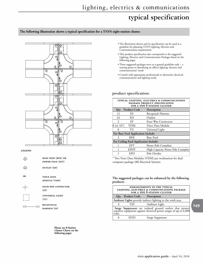
The following illustration shows a typical specification for a T/O/S eight-station cluster.
• The illustration shown and its specification can be used as aguideline for planning T/O/S Lighting, Electrics andCommunications requirements
• This product specification also corresponds to the suggestedLighting, Electrics and Communication Packages listed on thefollowing pages
• These suggested packages serve as a general guideline only – astarting point to identifying an office’s lighting, electrics andcommunications’ needs
• Consult with appropriate professionals to determine electrical,communications and lighting needs
The suggested packages can be enhanced by the followingproducts:
* Two Voice Data Modules (VDM) per workstation for dualcomputer package (8K Electrical System).
product specification:
()
()
- ()
Please see 8-StationCluster Charts on thefollowing pages
()
()
() ()
,
⁄⁄ - Qty Product Code Description12 ES Receptacle Harness24 ED Outlets 2 EF Four-Way Connectors
8 (or 16*) VDM Voice Data Module8 TU Universal Light
For Base Feed Application Include:2 BFK Base Feed
For Ceiling Feed Application Include:1 EPT Power Pole Complete1 EPHT High Capacity Power Pole Complete1 EPD Pole Divider
,
⁄⁄ - Qty Product Code Description
Ambient Lights provide indirect lighting to the work area.4 TAT Ambient Light
Surge Suppressors are isolated ground outlets that protectsensitive equipment against electrical power surges of up to 6,000volts.8 EDS5 Surge Suppressor
typical specification

lighting, electrics & communications
t/o/s application guide – April 30, 2018
suggested packages for 8-station cluster
Circuit 1 (Black)Circuit 2 (Red)Neutral (White)Ground (Green)
BenefitsDescriptionT/O/S Electrical System
• Most basic combination
• NOT recommended for computer applications or sensitiveelectronic equipment
• Each workstation has sufficient power for devices such as atypewriter, two bin lights and a pencil sharpener
• More power than the Budget Basic Package
• NOT recommended for computer applications or sensitiveelectronic equipment
• One or two of circuits can be designated for specificequipment
• Designated circuits are necessary for equipment that requires acontinuous draw of electricity (e.g. a coffee maker, fan andheater) or have high amperage (e.g. laser printer, smallphotocopiers and paper shredder)
Circuit 1 (Black)Circuit 2 (Red)Neutral (White)Ground (Green)
Isolated Circuit 5 (Orange)Isolated Neutral (White/Orange)Isolated Ground (Green/Orange)
• Low cost for workstations withoutcomputers and sensitive electronicequipment
• Separation from data cables
• Desk-height termination
• Flexible wire harnesses – non-Panelwidth specific and easy-to-handleangles
• Provides designated circuits for highamperage equipment or equipmentthat require a continuous draw
• Separation from data cables
• Desk-height termination
• Flexible wire harnesses – non-Panelwidth specific and easy-to-handleangles
4-Wire (4B), 2 general circuits per 4 workstations.
5-Wire (5D), 3 general circuits per 4 workstations.
• Basic package for workstations with computers
• Includes isolated circuit that should be designated to computers
• Remaining two general circuits meet other electrical needssuch as lighting
• Low cost for workstations withcomputers
• Isolated circuits prevent interferencefrom regular circuits that disruptscomputer use
• Separation from data cables
• Desk-height termination
• Flexible wire harnesses – non-Panelwidth specific and easy-to-handleangles
7-Wire, Isolated Ground (7G), 2 general circuits and 1 isolated circuit per 4 workstations.
Circuit 1 (Black)Circuit 2 (Red)Circuit 3 (Blue)Neutral (White)Ground (Green)
Computer Basic Package (7G Electrical System)
Budget General Package (5D Electrical System)
Budget Basic Package (4B Electrical System)
The following chart suggests lighting, electrics and communication packages that meet the diverse requirements of theoffice. These packages correspond to the typical specification listed in a previous page.

lighting, electrics & communications
t/o/s application guide – April 30, 2018
suggested packages for 8-station cluster (continued)
BenefitsDescriptionT/O/S Electrical System
• Recommended for workstations with computers
• More power than the Computer Basic Package
• Includes isolated circuit that should be designatedto computers
• One or two of circuits can be designated for specificequipment
• Ideal for computers and sensitive electronic equipment such aslaser printers, scanners, digitizers
• Sharing neutrals may cause interference between circuits
• Computers can be designated to isolated circuit and otherequipment to two circuits with separate neutral
Circuit 1 (Black)Circuit 2 (Red)Neutral (White)Ground (Green)
Isolated Circuit 5 (Orange)Isolated Circuit 6 (Blue)Isolated Neutral (White/Orange)Isolated Ground (Green/Orange)
• Isolated circuits prevent interferencefrom regular circuits that disruptscomputer use
• Allows designated circuits forhigh amperage equipment orequipment that require acontinuous draw
• Separation from data cables
• Desk-height termination
• Flexible wire harnesses – non-panel width specific and easy-to-handle angles
• Isolated circuits prevent interferencefrom regular circuits that disruptscomputer use
• Separate neutral for each circuitprevents interference betweenequipment on different circuits
• Separation from data cables
• Desk-height termination
• Flexible wire harnesses – non-panel width specific and easy-to-handle angles
• For workstations with two computers or with a computer andsensitive electronic equipment
• Offers 4 circuits that can handle high load requirements
• Two circuits are isolated sharing an isolated ground andisolated neutral, making it ideal for computer use
• Two isolated circuits accommodatetwo computers and preventinterference from regular circuitsthat disrupts computer use
• Total of 4 circuits can handle highelectrical load requirements
• Separation from data cables
• Desk-height termination
• Flexible wire harnesses – non-panelwidth specific and easy-to-handleangles8-Wire, Isolated Ground (8K),
2 general circuits and 2 isolated circuit per 4 workstations.
Dual Computer Package (8K Electrical System)
Computer Plus Sensitive Electronic Equipment Package (8N Electrical System)
Computer General Package (8T Electrical System)
The following chart suggests lighting, electrics and communication packages that meet the diverse requirements of theoffice. These packages correspond to the typical specification listed in a previous page.
Circuit 1 (Black)Circuit 2 (Red)Circuit 3 (Blue)Neutral (White)Ground (Green)
Isolated Circuit 5 (Orange)Isolated Neutral (White/Orange)Isolated Ground (Green/Orange)
8-Wire, Isolated Ground (8T), 3 general circuits and 1 isolated circuit per 4 workstations.
Circuit 1 (Black)Neutral (White)Circuit 2 (Red)Neutral (White/Red)Ground (Green)
Isolated Circuit 5 (Orange)Isolated Neutral (White/Orange)Isolated Ground (Green/Orange)
8-Wire, Isolated Ground (8N), 2 general circuits and 1 isolated circuit per 4 workstations.
Please Note: These suggested packages serve as a general guideline only. Consult with appropriate professionals to ensure a safe installation and that appropriatelocal codes are met.

lighting, electrics & communications
t/o/s application guide – April 30, 2018
casual wire basics
T/O/S offers options for casual wire management.
• Is specified as single units and can be applied to one or both sides of the Bridge (TPD)
• Can be ordered as part of the Bridge assembly or as a separate product
• Distributes wires from a Panel, along the Bridge to other worksurfaces or tables
• Can be used to manage the power cords of computer and electrical equipment
• Width is specified as the same dimension as the corresponding Bridge width
72" - 96"
• Slides up through the worksurface to provideeasy access to outlets concealed beneath thesurface and retracts to allow use of entireworksurface
• Includes three electrical outlets and is equippedwith a circuit breaker. The retractable featureallows concealment of the outlets
• Field-installed using the template provided withthe product. When installing on FreestandingModules Desks, take care to ensure that thelocation does not interfere with the wiretroughs
Bridge Tray (TZB)
• Base cable clips attach to the rail of Lyft ThinPanels to support casual wire routing
• No tools are required for securing clips
Retractable Power Center (EPC)
Base Cable Clips (Lyft) (HBCC)