Embed Size (px)
Citation preview

Design and specifications are each subject to change without notice. Ask factory for the current technical specifications before purchase and/or use.
Should a safety concern arise regarding this product, please be sure to contact us immediately.
Light Sensor (AMS3)
Photo IC type high sensitive light sensor
● Built-in optical fi lter : visibility characteristics close to human visibility● Liner photocurrent output proportionating to the brightness of surrounding environment● Environmentally-friendly silicon chip● RoHS compliant
Types
Ratings
Features
● Automatic lighting of lighting apparatus (domestic lighting, security light)● Day and night power saving operation of domestic appliances● Brightness detection of wall clocks (radio clocks)
● Absolute maximum ratings (Measuring condition: ambient temperature: 25 °C 77 °F)
● Recommended operating condition
Typical Applications
Through-hole type
Type (shape) PhotocurrentPart No.
Tape and reel package Baggage package
Through-hole type 260 μA✽ AMS302T AMS302
Item Symbol Absolute maximum ratings Remarks
Reverse voltage VR −0.5 V.DC to 8 V.DC −
Photocurrent IL 5 mA −
Power dissipation P 40 mW −
Operating temperature Topr −30 °C to 85 °C –22 °F to +185 °F Non-condensing at low temperatures
Storage temperature Tstg −40 °C to 100 °C –40 °F to +212 °F Non-condensing at low temperatures
Item Symbol AMS302 Remarks
Reverse voltageMinimum
VR
1.5 V.DC −
Maximum 6 V.DC −
Note: ✽Ev = 100 lx (Ev : Brightness, Fluorescent lamp is used as light source)
Standard packing : Tape and reel package Through-hole type : Carton : 2,000 pcs.; Case: 2,000 pcs. Baggage package Through-hole type : Carton : 500 pcs.; Case: 1,000 pcs.
Aug. 201500

Design and specifications are each subject to change without notice. Ask factory for the current technical specifications before purchase and/or use.
Should a safety concern arise regarding this product, please be sure to contact us immediately.
Light Sensor (AMS3)
0 20 40 60 80 1000
10
15
5
20
25
30
35
40
45
50
Ambient temperature (°C)
AMS302
Pow
er
dis
sip
ation (
mW
)
10 100 1000010001
10
1
100
1000
10000
0.1
Brightness (lx)
AMS302
Photo
curr
ent (μ
A)
500 600 700 800 900 1000 11004003000
0.2
0.1
0.4
0.6
0.8
0.3
0.5
0.7
0.9
1.0
human visibilityAMS302
Wavelength (nm)
Rela
tive s
ensitiv
ity
0−20−40 20 40 60 80 100+32−4−40 +68 +104 +140 +176 +212
0.6
0.8
1.0
1.2
1.4
Ambient temperature (°C °F)
AMS302
Rela
tive p
hoto
curr
ent
40 60 1008020+104 +140 +212+176+68
0.01
0.1
1
10
0.001
0.0001
Ambient temperature (°C °F)
AMS302
Dark
curr
ent
(μA
)
320 1 4 5 6 7 80
0.2
0.4
0.6
0.8
1.0
1.2
Reverse voltage (V.DC)
AMS302
Rela
tive p
hoto
curr
ent
IF
VO
tftr
90 %
10 %
White LED
Cathode
Anode
VCC
AMS✽✽✽
IF
RL
VO
VRAMS302 : 2.5 V
● Electrical and optical characteristics (Measuring condition: ambient temperature: 25 °C 77 °F)
Item Symbol AMS302 Condition
Peak sensitivity wavelength − lp 580 nm −
Photocurrent 1
Minimum
IL1
9.1 μA
VR=5 V.DC, Ev=5 lx ✽1Typical 13 μA
Maximum 16.9 μA
Photocurrent 2
Minimum
IL2
182 μA
VR=5 V.DC, Ev=100 lx ✽2Typical 260 μA
Maximum 338 μA
Photocurrent 3 Typical IL3 500 μA VR=5 V.DC, Ev=100 lx ✽2
Dark current Maximum ID 0.3 μA VR=5 V.DC, Ev=0 lx
Switching
time
Rise time Typical tr 8.5 msVcc=5.0 V.DC, V0=2.5 V.DC, RL=5 kΩ
Fall time Typical tf 8.5 ms
Note : ✽1 Fluorescent lamp is used as light source. Ev = Brightness ✽2 CIE standard illuminant ‘A’ is used as light source.
[Measuring method for switching time]
1. Power dissipation vs. ambient temperature characteristics
4. Photocurrent vs. brightness characteristics Light source : Fluorescent lamp Reverse voltage : 5 V.DC Ambient temperature : 25 °C 77 °F
2. Relative sensitivity vs. wavelength characteristics Reverse voltage : 5 V.DC Ambient temperature : 25 °C 77 °F
5. Relative photocurrent vs. ambient temperature characteristics Light source : Fluorescent lamp, Brightness : 100 lx Reverse voltage : 5 V.DC
3. Dark current vs. ambient temperature characteristics Reverse voltage : 5 V.DC
5. Relative photocurrent vs. reverse voltage characteristics Light source : Fluorescent lamp, Brightness : 100 lx Ambient temperature : 25 °C 77 °F
Reference Data
Aug. 201500
Design and specifications are each subject to change without notice. Ask factory for the current technical specifications before purchase and/or use.
Should a safety concern arise regarding this product, please be sure to contact us immediately.
Light Sensor (AMS3)
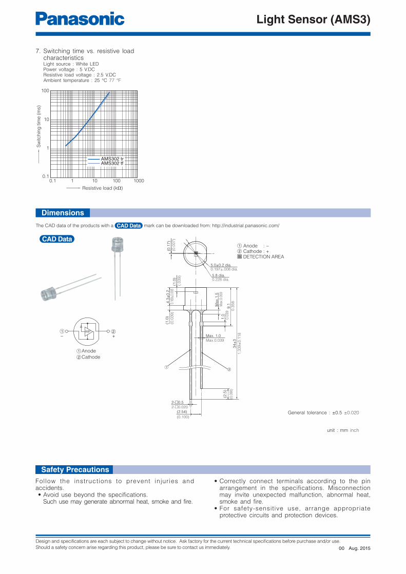
1001010.1 10000.1
1
10
100
Resistive load (kΩ)
AMS302 trAMS302 tf
Sw
itc
hin
g tim
e (
ms)
1 AMP 2
2Cathode
1Anode
− +
4.3
±0
.2
(2.54)
(0.100)
(1.0
)
0.16
9±0.
008
(0.0
39
)
2-□0.5
2-□0.020
34
±3
1.3
39
±0
.11
8
Ma
x.1
.5
(2.5
)
(0.0
98)
Max. 1.0Max.0.039
9.1
(1.0
)
(.0
39
)
(0.1
7)
(0.0
07
)
1.0
Max
.0.0
59
0.3
58
0.0
39
21
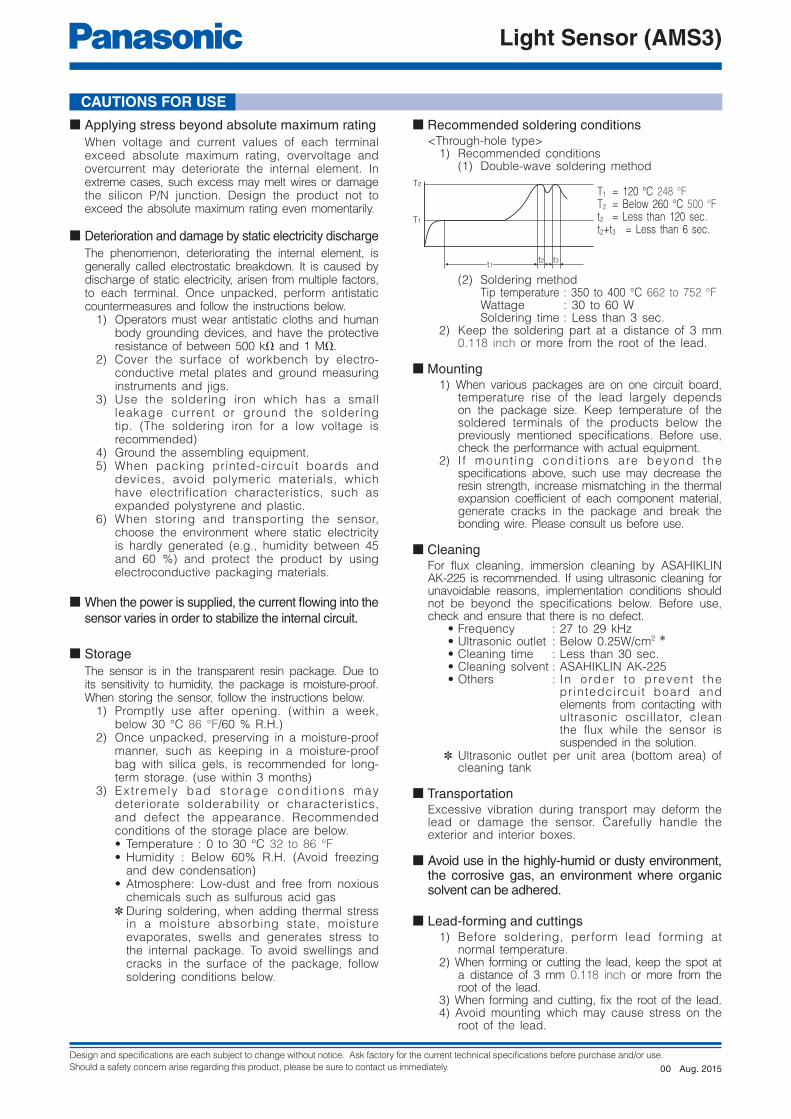
1 Anode : −2 Cathode : +
DETECTION AREA
5.0±0.2 dia.0.197±.008 dia.
5.8 dia.0.228 dia.
7. Switching time vs. resistive load characteristics Light source : White LED Power voltage : 5 V.DC Resistive load voltage : 2.5 V.DC Ambient temperature : 25 °C 77 °F
Dimensions
The CAD data of the products with a mark can be downloaded from: http://industrial.panasonic.com/
General tolerance : ±0.5 ±0.020
unit : mm inch
Safety PrecautionsFollow the instructions to prevent injuries and accidents. • Avoid use beyond the specifications. Such use may generate abnormal heat, smoke and fire.
• Correctly connect terminals according to the pin arrangement in the specifications. Misconnection may invite unexpected malfunction, abnormal heat, smoke and fire.
• For safety-sensitive use, arrange appropriate protective circuits and protection devices.
Aug. 201500
Design and specifications are each subject to change without notice. Ask factory for the current technical specifications before purchase and/or use.
Should a safety concern arise regarding this product, please be sure to contact us immediately.
Light Sensor (AMS3)
T1
T2
t1t2 t3
CAUTIONS FOR USE
■ Applying stress beyond absolute maximum rating
When voltage and current values of each terminal exceed absolute maximum rating, overvoltage and overcurrent may deteriorate the internal element. In extreme cases, such excess may melt wires or damage the silicon P/N junction. Design the product not to exceed the absolute maximum rating even momentarily.
■ Deterioration and damage by static electricity discharge
The phenomenon, deteriorating the internal element, is generally called electrostatic breakdown. It is caused by discharge of static electricity, arisen from multiple factors, to each terminal. Once unpacked, perform antistatic countermeasures and follow the instructions below.
1) Operators must wear antistatic cloths and human body grounding devices, and have the protective resistance of between 500 kΩ and 1 MΩ.
2) Cover the surface of workbench by electro-conductive metal plates and ground measuring instruments and jigs.
3) Use the soldering iron which has a small leakage current or ground the soldering tip. (The soldering iron for a low voltage is recommended)
4) Ground the assembling equipment.5) When packing printed-circuit boards and
devices, avoid polymeric materials, which have electrification characteristics, such as expanded polystyrene and plastic.
6) When storing and transporting the sensor, choose the environment where static electricity is hardly generated (e.g., humidity between 45 and 60 %) and protect the product by using electroconductive packaging materials.
■ When the power is supplied, the current fl owing into the
sensor varies in order to stabilize the internal circuit.
■ Storage
The sensor is in the transparent resin package. Due to its sensitivity to humidity, the package is moisture-proof. When storing the sensor, follow the instructions below.
1) Promptly use after opening. (within a week, below 30 °C 86 °F/60 % R.H.)
2) Once unpacked, preserving in a moisture-proof manner, such as keeping in a moisture-proof bag with silica gels, is recommended for long-term storage. (use within 3 months)
3) Ext remely bad storage condi t ions may deteriorate solderability or characteristics, and defect the appearance. Recommended conditions of the storage place are below. • Temperature : 0 to 30 °C 32 to 86 °F• Humidity : Below 60% R.H. (Avoid freezing
and dew condensation)• Atmosphere: Low-dust and free from noxious
chemicals such as sulfurous acid gas✽ During soldering, when adding thermal stress
in a moisture absorbing state, moisture evaporates, swells and generates stress to the internal package. To avoid swellings and cracks in the surface of the package, follow soldering conditions below.
■ Recommended soldering conditions<Through-hole type>
1) Recommended conditions(1) Double-wave soldering method
T1 = 120 °C 248 °FT2 = Below 260 °C 500 °Ft2 = Less than 120 sec.t2+t3 = Less than 6 sec.
(2) Soldering method Tip temperature : 350 to 400 °C 662 to 752 °F Wattage : 30 to 60 W Soldering time : Less than 3 sec.
2) Keep the soldering part at a distance of 3 mm 0.118 inch or more from the root of the lead.
■ Mounting1) When various packages are on one circuit board,
temperature rise of the lead largely depends on the package size. Keep temperature of the soldered terminals of the products below the previously mentioned specifications. Before use, check the performance with actual equipment.
2) I f mount ing condi t ions are beyond the specifications above, such use may decrease the resin strength, increase mismatching in the thermal expansion coefficient of each component material, generate cracks in the package and break the bonding wire. Please consult us before use.
■ CleaningFor flux cleaning, immersion cleaning by ASAHIKLIN AK-225 is recommended. If using ultrasonic cleaning for unavoidable reasons, implementation conditions should not be beyond the specifications below. Before use, check and ensure that there is no defect.
• Frequency : 27 to 29 kHz • Ultrasonic outlet : Below 0.25W/cm2 ✽
• Cleaning time : Less than 30 sec. • Cleaning solvent : ASAHIKLIN AK-225 • Others : In order to prevent the
printedcircuit board and elements from contacting with ultrasonic oscillator, clean the flux while the sensor is suspended in the solution.
✽ Ultrasonic outlet per unit area (bottom area) of cleaning tank
■ TransportationExcessive vibration during transport may deform the lead or damage the sensor. Carefully handle the exterior and interior boxes.
■ Avoid use in the highly-humid or dusty environment, the corrosive gas, an environment where organic solvent can be adhered.
■ Lead-forming and cuttings1) Before soldering, perform lead forming at
normal temperature.2) When forming or cutting the lead, keep the spot at
a distance of 3 mm 0.118 inch or more from the root of the lead.
3) When forming and cutting, fix the root of the lead.4) Avoid mounting which may cause stress on the
root of the lead.
Aug. 201500

Design and specifications are each subject to change without notice. Ask factory for the current technical specifications before purchase and/or use.
Should a safety concern arise regarding this product, please be sure to contact us immediately.
Light Sensor (AMS3)
D0
Δp Δh
H
L
F
P2 P
P0
W
W W0
W2
1
Anode side Cathode side
Note : Zigzag tape style is used.
● The following shows the packaging format
Through-hole type tape and reel (mm inch)
Type Tape dimensions
Light sensor
NaPiCa
Through-hole type
AMS302T
Term Symbol Explanation
Reverse voltage VR The applied voltage between the cathode and anode.
Photocurrent IL The current that fl ows between the cathode and anode when light is applied.
Power dissipation P The electric power loss that occurs between the cathode and anode.
Operating temperature ToprThe workable ambient temperature range at which normal operation is possible
under the condition of a prescribed allowable loss.
Storage temperature TstgThe ambient temperature range at which the sensor can be left or stored without
applying voltage.
Peak sensitivity wavelength lp The wavelength of light at which sensitivity is at its maximum.
Dark current IDThe current between the cathode and anode when reverse voltage is applied during
darkness.
Rise time tr Time required for the output waveform to rise from 10 % to 90 % when light is applied.
Fall time tf Time required for the output waveform to fall from 90 % to 10 % when light is cut.
Light Sensor NaPiCa terminology
Item Symbol Dimensions Remarks
Feed hole pitch
P012.7±0.30.500±0.012
Product interval pitch
P12.7±1.00.500±0.039
Product distance
P26.35±1.30.250±0.051
Product bottomdistance
H20.5±1.00.807±0.039
Lead interval F2.54±0.50.100±0.020
Product slant Δh0±1.0
0±0.039
Product tilt Δp0±1.0
0±0.039
Tape width W18.0+1.0
0.709+0.039
Holding tape width
W013.0±0.30.512±0.012
Feed hole position
W19.0+0.75
0.354+0.030
Holding tape distance
W20 to 0.5
0 to 0.020
Feed hole diameter
D03.8±0.2
0.150±0.008
Tape thickness
t0.5±0.20.020±0.008
Included holdingtape thickness
Defective productcutoff position
LMax:11.0Max:0.433
−0.5
−0.020
−0.020
−0.50
Aug. 201500


![^ u o o µ ] o ] v P W ] ] ] } v > } v W } P u...h August 2020 ^ u o o µ ] o ] v P W ] ] ] } v > } v W } P u, Z [ ^ u o o µ ] o ] v P W ] ] ] } v > } v W } P u } À ] P } i ( ] v](https://img.dokumen.tips/doc/110x75/61255bcc660d0b5c0765fc8b/-u-o-o-o-v-p-w-v-v-w-p-u-h-august-2020-u-o-o-.jpg)


![NATY - frigerio-corazza.com · W } ] o o & ] P ] } } Ì Ì ^ o W P ] v î ] ñ W } ] o o & ] P ] } } Ì Ì ^ o W P ] v ï ] ñ](https://img.dokumen.tips/doc/110x75/5fcfe2c0ec79a344b664dcdf/naty-frigerio-w-o-o-p-oe-oe-o-w-p-v-w-o-o-.jpg)


![Stroud District Playing Pitch Strategy Final Strategy June ... · ^ } µ ] ] W o Ç ] v P W ] Z ^ P Ç W & ] v o ^ P Ç ^ } µ ] ] W o Ç ] v P W ] Z ^ P Ç W & ] v o ^ P Ç](https://img.dokumen.tips/doc/110x75/5f4d47452b8d3e336c3a6031/stroud-district-playing-pitch-strategy-final-strategy-june-w-o-.jpg)


![v o ] ] ( l ] ( ] < i W v P v P l v v W P ] v W v P v } v](https://img.dokumen.tips/doc/110x75/61591b625c7eb4590a66de63/v-o-l-lt-i-w-v-p-v-p-l-v-v-w-p-v-w-v-p-v-v-.jpg)


