Embed Size (px)
Citation preview

www.led-professional.com
Review
ISSN 1993-890X
The technology of tomorrow for general lighting applications May/June 2010 | Issue 19
LpR
Light & Building ReviewThe Future of OLED Lighting
Distributor Report

© 2010 Avago Technologies. All rights reserved.
Your Imagination, Our Innovation
Your Imagination: 100,000 travelers rushing through an airport on a holiday weekend looking for an easy to read sign to locate their departure gate.
Our Innovation: Avago Technologies delivers the Worlds First SMT LED High Brightness Lamp designed for outdoor full color signs.
By allowing designers to utilize both sides of a PCB, our surface mount lamps allow for thinner, lighter signs while enabling pick and place assembly resulting in faster cycle times.
If a commitment to technical excellence and innovative solutions on Signs and Signal applications is critical to your design, contact Avago for a free sample. www.avagoresponsecenter.com/317
Imagine...
the World’s First SMT Lamp
LED professional Review | May/June 2010 | pagewww.led-professional.com 1
Copyright © 2010 Luger Research & LED-professional. All rights reserved.
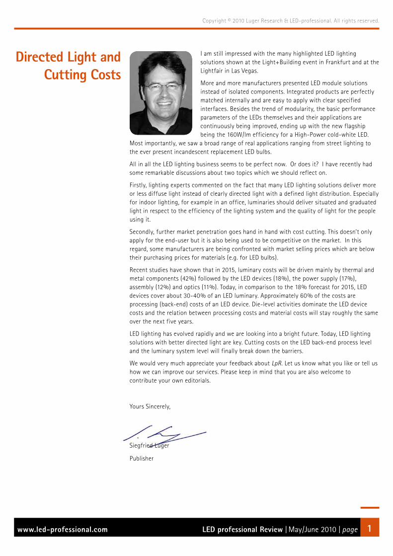
I am still impressed with the many highlighted LED lighting solutions shown at the Light+Building event in Frankfurt and at the Lightfair in Las Vegas.
More and more manufacturers presented LED module solutions instead of isolated components. Integrated products are perfectly matched internally and are easy to apply with clear specified interfaces. Besides the trend of modularity, the basic performance parameters of the LEDs themselves and their applications are continuously being improved, ending up with the new flagship being the 160W/lm efficiency for a High-Power cold-white LED.
Most importantly, we saw a broad range of real applications ranging from street lighting to the ever present incandescent replacement LED bulbs.
All in all the LED lighting business seems to be perfect now. Or does it? I have recently had some remarkable discussions about two topics which we should reflect on.
Firstly, lighting experts commented on the fact that many LED lighting solutions deliver more or less diffuse light instead of clearly directed light with a defined light distribution. Especially for indoor lighting, for example in an office, luminaries should deliver situated and graduated light in respect to the efficiency of the lighting system and the quality of light for the people using it.
Secondly, further market penetration goes hand in hand with cost cutting. This doesn’t only apply for the end-user but it is also being used to be competitive on the market. In this regard, some manufacturers are being confronted with market selling prices which are below their purchasing prices for materials (e.g. for LED bulbs).
Recent studies have shown that in 2015, luminary costs will be driven mainly by thermal and metal components (42%) followed by the LED devices (18%), the power supply (17%), assembly (12%) and optics (11%). Today, in comparison to the 18% forecast for 2015, LED devices cover about 30-40% of an LED luminary. Approximately 60% of the costs are processing (back-end) costs of an LED device. Die-level activities dominate the LED device costs and the relation between processing costs and material costs will stay roughly the same over the next five years.
LED lighting has evolved rapidly and we are looking into a bright future. Today, LED lighting solutions with better directed light are key. Cutting costs on the LED back-end process level and the luminary system level will finally break down the barriers.
We would very much appreciate your feedback about LpR. Let us know what you like or tell us how we can improve our services. Please keep in mind that you are also welcome to contribute your own editorials.
Yours Sincerely,
Siegfried Luger
Publisher
Directed Light andCutting Costs

LED professional Review | May/June 2010 | pagewww.led-professional.com 2
Copyright © 2010 Luger Research & LED-professional. All rights reserved.
Front-page pictureArtwork: Thomas Klobassa, ©LED professional 2010 L-Price LED bulb with remote phosphor from Philips
Copyrights – Luger Research e.U.
The editors make every reasonable effort to verify the information published, but Luger Research e.U. assumes no responsibility for the validity of any manufacturers, non profit organisations or individuals claims or statements. Luger Research e.U. does not assume and hereby disclaims any liability to any person for any loss or damage caused by errors or omissions in the material contained herein, regardless of whether such errors result from negligence, accident or any other cause whatsoever. You may not copy, reproduce, republish, download, post, broadcast, transmit, make available to the public, or otherwise use LED professional Review (LpR) content without prior written consent from Luger Research e.U. – Institute for Innovation & Technology, Austria.
LED professional Review (LpR) - Annual Subsriptions
LpR Digital Magazine
6 issues•
pdf download•
high resolution pictures and graphs•
printable•
commercial use•
access to all previous issues•
Euro 78.80•
http://www.led-professional.com/•subscriptions
LpR Printed Magazine
6 issues•
Euro 158.40•
Next LpR Issue - July/Aug 2010
LED Testing, Simulation & •Manufacturing
ImprintLED professional Review (LpR)
ISSN 1993-890X
Publisher
Luger Research e.U.Institute for Innovation & Technologydep LED professionalFaerbergasse 15, Haus RotA 6850 Dornbirn, Austria / Europephone +43 5572 394 489fax +43 5572 394 489 [email protected]
Publishing Editors
Siegfried LugerArno Grabher-Meyer
Account Manager
Theresa Koenig

LED professional Review | May/June 2010 | pagewww.led-professional.com 3
Copyright © 2010 Luger Research & LED-professional. All rights reserved.
Content
Editorial p1
Imprint p2
Product News p5
Event Reports
Light+Building Review by Arno Grabher-Meyer, LED professional p20
New Era for LEDs in Lighting by Alan R. Mills PhD., LED professional p28
Applications
Incandescent Replacement Lamps and Health by Wout van Bommel, Van Bommel Lighting Consultant p30
The Future of OLED Lighting by Ian Ashdown, byHeart Consultants Ltd; Brent York, Tangenesys Consulting Ltd. p34
LED High Bay Lighting by Michael Schratz, Dialight Corp. p38
Optics
Design and Manufacture of Achromatic Lenses by Christoph Gerhard, Dr. Geoff Adams and Stephanie Wienecke p40
Drivers
About PLC Reliability by Ashish Garg & Angad Singh Gill, Cypress Semiconductor Corp. p44
Exploration on Transmission Technology of RGB LED in Architectural Lighting by Tiger Yen and Jerome Lee, Macroblock, Inc. p48
Optimizing LED Drivers for Power, Display Life and the Visual Experience by Irene Signorino, Arkadiy Peker, Kevin Choi, Microsemi Corp. p53
Special Topics
Component Distributors – Partners for the LED Industry by Ingo Guertler, Europartners Consultants; Siegfried Luger, LED professional p58
LED professional – Patent Report p60
Advertising IndexAvago Technologies p C2
DSM Engineering Plastics p 4
Sharp p 11
CREE p 15
Setron p 18
OSRAM p 19
EBV Elektronik p 23
EldoLED p 27
Infineon p 29
Ocean Optics p 29
Vossloh-Schwabe p 33
CIOE Fair Shenzhen p 37
Taitronics p 41
Instrument Systems p 43
OLED Lighting Design Summit p 45
Signcomplex p 47
Light Middle East p 49
Forum LED p 51
Road Lamp Fair p 52
Kingbright Electronic p 54
LED Fair p 57
Lumiville / Inlight Expo p C3
Seoul Semiconductor p C4

Proven LED thermal management solution
Developing a polymer solution for thermal management in
LED applications was a challenging task. But fi nally the
DSM Knowledge Team has found a solution they can warmly
recommend. With Stanyl TC the heat dissipation is brilliantly
combined with design fl exibility and the high productivity of
polymer technology.
Stanyl® TC is rapidly establishing a position as the material
of choice for the LED Lighting industry. It’s the fi rst thermally
conductive plastic which has an optimal balance of
mechanical performance and heat dissipation properties.
It offers lighting producers and designers the ultimate design-
freedom, whilst providing all the necessary metal replacement
benefi ts, such as weight saving, higher productivity, easy
processing and overall system cost savings.
All this is made possible by the broad knowledge we can draw
on, not to mention our endless curiosity and our care
for a greener planet. With all the passion we have, we want
to create proven innovations for generations to come. More
information: www.livingsolutions.dsmep.com
Stanyl® TC Thermal conductivity combined with design freedom for LED lighting Stanyl® is a registered trademark of Royal DSM N.V.
Stanyl® TC

LED professional Review | May/June 2010 | pagewww.led-professional.com 5
Copyright © 2010 Luger Research & LED-professional. All rights reserved.
Product News
Cooper Lighting Expands Halo LED Recessed Downlight OfferingCooper Lighting, a division of Cooper Industries plc, has expanded its Halo LED H7 Collection offering additional choices in LED color temperatures and higher lumen options. The 6” LED downlight product line expansion–from the original Halo LED 600 Series–now includes the Halo LED 900 Series and Halo LED 1200 Series, offering a wide and versatile selection of energy-efficient LED recessed downlighting options for general lighting in commercial, retail, institutional and residential applications.
The Halo LED 1200 Downlight Series delivers in the range of 862-1541 lumens.
Designed for new construction projects or to retrofit existing 6” nominal compatible housings (with an Edison screw base adapter included with the module), the Halo LED H7 Collection features excellent color rendering (80 CRI) and offers the industry’s widest selection of color temperatures (2700K, 3000K, 3500K and 4000K). The superior optical design yields productive beam lumens providing smooth, even illumination, excellent cutoff and extremely low glare.
Consuming less than 15W, the Halo LED 900 Series modules deliver between 511-945 lumens–up to 66 lumens per watt (LPW)–depending upon the selected trim and color temperature. The series exceeds the light output and distribution of a 75W PAR30 or PAR38 halogen lamp, 85W BR40 or a 26W compact fluorescent luminaire.
The Halo LED 1200 Downlight Series delivers in the range of 862-1541 lumens depending upon the trim and color temperature selected and offers comparable light output and distribution of a 90W PAR38 halogen lamp, a 120W BR40 incandescent lamp, or a 32W compact fluorescent luminaire (lamp & reflector trim). Consuming only 24.8W, the high efficacy luminaire delivers up to 62 LPW. The Halo 1200 Series LED modules are universal voltage (120-277V).
The downlights are designed to deliver greater than 70% of initial lumens at 50,000 hours and feature a full range of dimming capabilities. For added retrofit capability, a new Retrofit Adapter Band (ML7RAB) is available for retrofitting housings that do not have torsion spring receivers.
The Halo LED H7 Collection is ENERGY STAR® qualified and can be used for California Title 24-2008 and IECC-2009 High Efficacy compliance with designated LED modules and LED trims. The LED downlights go through a serialized testing and measurement process that ensures color and lumen consistency that exceed ENERGY STAR® Solid State Lighting (SSL) Luminaire program standards.
The Halo LED H7 Collection is ideally suited for commercial, hospitality, healthcare, retail and residential applications.
High Efficient, Color Tunable LED-DownlightLUMITECH Produktion und Entwicklung GmbH presented for the first time its tuneable white light LED-Downlight E8 portfolio for “Individual Lighting” solutions at the Light+Building, Frankfurt, April 11th-16th, 2010. The LED-Downlight E8 offers highest quality white light, individually tuneable from warm white (2700 Kelvin) up to cool white (6500 Kelvin) thus allowing customised adjustments from “Morning Sun” to “Moonlight” and up to “Firelight” with a Colour Rendering Index (CRI) of 90. The E8 offers a comparable performance at 12W to 75W Halogen Lamps or 26W Compact Fluorescent Lamps (CFL), energy savings of up to 83% and a long lifetime of up to 35,000 hours.
LUMITECH’s LED-Downlight E8 is based on PI-LED® technology.

LED professional Review | May/June 2010 | pagewww.led-professional.com 6
Copyright © 2010 Luger Research & LED-professional. All rights reserved.
Main Technical Data:• LED Source COB LED-Modul• Voltage: 24 V DC• Power consumption: 12 W• Luminous flux: 1000 lm• Efficiency: 83 lm/W• System Efficiency: 82% (LOR)• CCT: 2,700 K (warm white) to 6.500 K (cool white)• CRI, Ra: 90 • Protection: IP 40
“The E8 portfolio has been created to offer individual lighting solutions for application in areas where not only adaptability, cost-effectiveness, and energy-efficiency, but also individuality, are the focus of the end-user” states Mr. Erwin Baumgartner, Managing Director, LUMITECH. The E8 Downlight offers tuneable white light, enhancing well-being in accordance with human biorhythms, and is therefore perfectly suited for application in restaurant, hotel, wellness and residential lighting.
Based on PI-LED® technology, LUMITECH’s LED light engines, was also featured at the fair, demonstrating individual light control for best “Value Lighting” and developed for application in shops and museums. With the correct colour temperature, goods are demonstrably fresher and more attractive looking.
LUMITECH’s LED light engines can be used to place products such as clothing, jewellery and food items in their best light, as well as providing a UV/IR free solution for museum lighting.
LedEngin, Inc. Announces Production Availability of LuxSpot™ AltaLedEngin, Inc. announced the immediate availability of LuxSpot™ Alta, the latest addition to the LuxSpot family of LED modules. LuxSpot Alta delivers over 6000 Lux at 21 watts of power, beating traditional 75W halogen MR16 lamps in performance at 10 times the service life.
LuxSpot Alta shares the same sleek, compact form as the standard LuxSpot with over double the lumens and lux opening up additional track and downlighting applications previously unattainable with LED solutions. The high quality, uniform light and excellent color quality coupled with its high performance lumen output - over 1200 lumens in 5500K, makes LuxSpot Alta the product of choice for many retail, hospitality and commercial directional lighting applications. LuxSpot Alta is available in warm, neutral and daylight color temperatures and narrow flood and flood beam distributions. Like the ultra-compact LuxSpot, LedEngin’s new LuxSpot Alta is powered by the company’s industry-leading multichip LED emitter and proprietary secondary optics.
LuxSpot™ Alta is the latest addition to the LuxSpot family of LED modules.
LedEngin LuxSpot Alta lamps deliver:• Center Beam Candle Power: (CBCP) over 6000 cd in narrow flood
beam and 3450 cd in flood beam in Daylight White (5500K). CBCP of 4250 cd in narrow flood beam in Warm White (3100K).
• Lumens: 1250 lm in Daylight White and 900 lm in Warm White.• Energy Savings: 70% as compared with 75W halogen MR16 lamps.• Life expectancy: 35,000 hours.• Power consumption of 21W• Full range of CCT: 2700K, 2900K, 3100K, 3500K, 4100K, 5500K• Beam distributions: Narrow flood and flood• Warranty: Three year limited warranty.
“We are pleased to offer customers our next-generation LED light source module, LuxSpot Alta, which is form and fit compatible to LuxSpot with over 2x the performance enabling many new applications for track and downlights. LuxSpot Alta provides over 70% power consumption savings compared to 75W halogen source yielding less than one year Return on Investment (ROI) in many retail and hospitality lighting applications. We have had excellent feedback from our premier customers on LuxSpot Alta and I look forward to commercial roll out of this product at other major fixture manufacturers,” said David Tahmassebi, chief executive officer, LedEngin, Inc.
Light Based Technologies: Leading-Edge Dimming TechnologyLight-Based Technologies Inc. has partnered with Bridgelux, Inc., of Livermore, California, USA, and Elpro Lichttechnik GMBH, of Arnsberg, Germany, to bring to market the new Gamma line of high performance, energy efficient, fully dimmable LED luminaires.
The high quality, cost-effective Gamma product line features the Bridgelux Warm White RS Array delivering 3000 lumens. The products also feature market-leading optical control, mechanical design and an innovative passive thermal management solution from Elpro; as well as control and power management from Light-Based Technologies through the use of their LB4 integrated circuit.

LED professional Review | May/June 2010 | pagewww.led-professional.com 7
Copyright © 2010 Luger Research & LED-professional. All rights reserved.
Elpro’s Gamma LED Spotlight is equiped with the Bridgelux Warm White RS Array delivering 3000 lumens and Light Based Technologies’ LB4 driver IC.
The Gamma products operate with conventional triac (phase-cut) dimmer switches and deliver superior, flicker-free performance with dimming capability to less than 1%. The LB4 integrated circuit delivers a significantly higher system efficiency compared to other triac compatible driver solutions to further enhance energy savings. The Gamma product series is compatible with commonly available cost-efficient dimmer switches that lighting designers and customers demand, simplifying the installation process within existing building infrastructures.
LED technology has made dramatic advancements over the past few years. Today’s leading-edge LED lighting technologies deliver the required quantity and quality of light, and feature the aesthetics and thermal management capabilities, in cost-effective solutions to displace conventional lighting technologies. “Elpro has a history of flexibility and innovation, so we are very proud to offer cutting edge LED technology that really satisfy customers’ demands,” said Horst Wiegelmann, Executive Director of Elpro.
With an estimated 150 million phase cut dimmers installed in North American residences, Jeanette Jackson, CEO of Light-Based Technologies, stated: “Triac, or phase cut, dimming is especially important due to the massive installed base, which is why we focused on developing our best-in-class solution.”
“The Gamma line is the result of a successful collaboration between three technology leaders committed to bringing to market high quality, energy efficient solid state lighting products to transform the global lighting industry into a $100 Billion dollar market opportunity. Bridgelux is focused on delivering integrated plug and play solutions tailored specifically for lighting, where energy savings, design flexibility and other benefits are beginning to drive massive adoption of solid state lighting,” says Jason Posselt, Vice-President of Marketing for Bridgelux.
MEGAMAN® LED: Retrofit for Conventional LampsMEGAMAN® marked a new era for the lighting industry by launching its ground breaking LED Lamp series, which offers a direct one-for-one replacement for halogen, metal halide and incandescent lamps. The MEGAMAN LEDs have comparable light intensity and colour consistency to their counterparts, but save up to 80% energy and generate much less heat.
Some LED retrofit lamps out of the MEGAMAN® portfolio.
Metal Halide Replacement:MEGAMAN® LED Metal Halide Replacement Series is developed to replace conventional metal halide lamps. With the patented Thermal Conductive HighwayTM (TCH) technology, heat is dissipated efficiently, minimizing deterioration towards the LED chip and other components.
With efficient thermal management, the MEGAMAN® LEDs provide high light output and lumen maintenance. Reaching a supreme luminous intensity, comparable to a higher wattage metal halide equivalents, this LED series delivers sound energy savings in operation. In addition to a lifetime of up to 40,000 hours, maintenance costs can be significantly reduced.
MEGAMAN® LED lamps also outperform the metal halide lamps as an instant-start and instant-restart lighting solution. The MEGAMAN® LED PAR38 is the first true retrofit to PAR38 Metal Halide Lamp while the models in AR111 and PAR30L support smooth diming from 100% to 1%.
LED MR16 Reflectors:MEGAMAN® announced the launch of a new series of MR16-compatible LED reflector lamps. The MEGAMAN® MR16 LED Reflectors feature excellent performance with 80% energy savings and low heat output, making it an ideal replacement for the blazing hot halogen. The MEGAMAN® MR16 LED Reflector is compact, with a GU5.3-compatible lamp cap and a beam angle of 36°.

LED professional Review | May/June 2010 | pagewww.led-professional.com 8
Copyright © 2010 Luger Research & LED-professional. All rights reserved.
With the patented “Thermal Conductive HighwayTM technology, the MR16 LED is optimized for a long lifetime of 30,000 hours to lower maintenance costs and provides the highest luminance comparable to its halogen counterparts. They are available in 8W and 10W to replace 35W and 50W halogen lamps. The MEGAMAN® MR16 LED Reflectors have a colour rendering index of up to 92. 100% to 1% linear dimming can be achieved.
LED Candle Series:At Light+Building 2010, MEGAMAN® showcased the new LED Candle Series, which resembles a point light source of incandescence. These LED Candles are designed to replace the incandescent candles. The MEGAMAN® LED Candle in 5W delivers a 180 lumen light output and a high CRI of 85 at a size equivalent to a 25W incandescent candle. With a unique ‘heat sink’ design for heat dissipation, the lamp enjoys a long lamp life of 30,000 hours and releases much less heat in operation, while also saving 80% power over incandescents.
The MEGAMAN® LED Candle Series is available in different glass cover finishings including the twisted glass, smooth glass and twisted golden cover. The MEGAMAN® LED Mini Classic in 5W can replace the P45 incandescent in 25W with a comparable size and 80% power savings.
Double-click and LED Replacement for 60 Watt Incandescent LampsAt Light+Building 2010, LEDON Lamp GmbH presented its extended product range of LED retrofit lamps for the first time.
Newly developed 10W LED replacement lamp for 60W incandescent bulbs will be available soon.
While LEDON lamps have so far replaced conventional 25 Watt and 40 Watt incandescent lamps, the extended portfolio of LEDON Lamp offers innovative and new developments in terms of shape and wattage. These include the two 5 Watt LED lamps replacing 25 watt
incandescent lamps in the shape of golf balls and candles. A particular highlight in the new LEDON product range is the 10 Watt LED lamp replacing the classic 60 Watt incandescent lamp. The 6 Watt LED replacement for 40 Watt incandescent globe lamps rounds off the extended portfolio. Due to the extended product range, LEDON Lamp now offers a suitable lighting solution for every household.
“We are very proud to present our new developments at Light+Building, particularly because LEDON Lamp was only founded nine months ago. This has only been possible because we have been able to rely on 10 years of LED expertise and on the resources of the entire Zumtobel Group. The products are ready to go into production and will be available from stock this summer. Our objective is, true to our slogan “LEDON – my light“, to offer consumers the best LED lamps including a very pleasant lighting quality and colour. Therefore, we are already working at full speed on the next generation of our product range“, said Detlef Mikulsky, general manager of LEDON Lamp GmbH.
Acriche: High Luminous Efficiency of 150 lm/WSeoul Semiconductor has announced that Acriche, which is made by its own patented technology and driven by an alternating current power source for household or industrial use, achieved a luminous efficiency of 100 lm/W in February, the company began to put the product into mass production in April and it also recently succeeded in achieving 150 lm/W.
Full-scale mass production of 100 lm/W has just begun and mass production of 150 lm/W is close due to rapid progress in research and development.
The mass production of 150 lm/W is scheduled to begin by the end of the year accelerating the replacement of halogen lamps, incandescent light bulbs and fluorescent lighting with LED technology. The European Union’s legeslation banning the sale of incandescent light

LED professional Review | May/June 2010 | pagewww.led-professional.com 9
Copyright © 2010 Luger Research & LED-professional. All rights reserved.
bulbs of more than 100 Watts from September 2009 and future steps to ban all use of inefficient conventional electric lighting are being seen as a turning point for LED adoption.
Acriche is the world’s only semiconductor light source that can be driven by a alternating current power source without the need of an AC-DC converter. This ability to operate without the use of a converter results in a significant reduction in energy losses and additional cost savings compared to standard DC LED technology, Acriche also offers a reduction in the enviromental impact of lighting, reducing carbon dioxide emissions without a compromise in brightness or quality of light. Due to these advantages, two of the world’s largest lighting companies already have products, for lighting applications, in mass production using the Acriche. In addition, more than 100 companies are beginning to utilse the Acriche in various applications. This latest development in technology has enhanced the reputation of Seoul Semiconductor as a world leader in environmentally friendly LED manufacture, by rapidly accelerating the development alternative soultions to conventional lighting.
Illumitex Unveils Aduro™ Series of High Power LEDsIllumitex, Inc., a developer of revolutionary high-brightness light emitting diodes (LEDs), revealed its first breakthrough product line, the Aduro™ series of packaged LEDs. The Aduro series transforms LED lighting design by emitting uniform, narrow-beam white light without the need for expensive, inefficient secondary optics. Based in Austin, Texas, with strong backing from world-renowned investors such as New Enterprise Associates, Illumitex is changing the way lighting is envisioned by enabling the most efficient and cost-effective LED lighting solutions in the world.
Illumitex Aduro™ ITX-500 and Aduro™ ITX-125 with nominal 500 and 125 lumens and radiation patterns of 10, 20 and 30 degree beam half-angles.
“What Illumitex has achieved is a fundamental breakthrough in delivering the most usable lumens to the task surface, thus providing unrivaled overall lighting system efficiency,” said Matt Thomas, CEO of Illumitex. “We have reinvented the basic die and package structure to create the industry’s most optically advanced LED. Our technology allows us to deliver perfectly uniform light exactly where the customer wants it.”
LEDworks, an Illumitex customer headquartered in Singapore, is currently leading a major lighting upgrade using Aduro-enabled lighting fixtures. “Illumitex has developed the most efficient and cost-effective LED lighting solution on the market,” said Philip Mak, CEO of LEDworks. “We are using Illumitex LEDs to create the industry’s highest performing lighting fixtures. The Aduro product line represents a huge leap forward in light quality. We view this installation as the first of many collaborations.”
Until now, traditional LED manufacturers have used a basic dome optic in an attempt to control the light output from the package. However, this has forced fixture manufacturers to utilize costly, inefficient secondary optical lenses and reflectors. Illumitex solves this problem with a breakthrough approach to light extraction that eliminates the cost and energy efficiency issues associated with secondary optics. The Illumitex solution results in a highly efficient and uniform distribution pattern at the beam angle of the customer’s choice.
Everlight Expands the Shuen LED Family with a Brand New 3W VersionAdding to the performance and popularity of Everlight’s 1W Shuen series High Power LED with a luminous flux up to 100 lm at 350 mA, Everlight Electronics Co., Ltd. (TSE:2393) announced the brand new 3W Shuen High Power LED with up to 170 lm when driving at 700 mA.
Everlight’s Shuen LEDs are now also available in a 3 Watt version.

LED professional Review | May/June 2010 | pagewww.led-professional.com 10
Copyright © 2010 Luger Research & LED-professional. All rights reserved.
Both, 1W and 3W Shuen packages are surface-mount high-power devices offering high brightness in a compact and slim form factor, making them suitable for different lighting applications including general illumination, flash, spot, signal, industrial and commercial lighting. The thermal pad of both the 1W and 3W Shuen Series are electrically isolated providing for improved thermal and electrical characteristics. It is well known that the benefits of LED devices are their environmentally friendly nature, energy savings, reliability and long life. All Shuen families exhibit these advantages while providing high efficiency luminous output.
The Shuen series not only offers slim size and high luminosity, but provides customers the flexibility of various CRI (Color Rendering Index) with 75 and 90 depending on their lighting applications. Within the global Solid-State Lighting market, Everlight strives to conform to all environmental initiatives. The Shuen series meets the European Union directives on the Restriction of Hazardous Substances in electronic equipment - namely the RoHS directive. All materials and processes of the Shuen series are free of form lead, mercury, cadmium, hexavalent, polybrominated biphenyls (PBB) or polybrominated diphenyl ethers (PBDE).
Features:• Small package with high efficiency• Typical view angle of 120°• ESD protection up to 8KV• Soldering method: SMT• Binning Parameters: Brightness, Forward Voltage ,Wavelength and
Chromaticity• Moisture Sensitivity Level: 1• RoHS compliant• Matches ANSI binning• Electrically isolated thermal pad
Applications:• General Lighting• Decorative and Entertainment Lighting• Commercial Lighting• Industrial Lighting• Signal and Symbol Luminaries
Everlight is also promoting closer working relationships between the R&D, Sales and Marketing teams to better meet and exceed the customer’s expectations in both product offering and technology perspectives. The Shuen LED series and its many technical features are a result of fostering a closer relationship between these teams.
Tyco Electronics: Solderless Socket Solution for the New Cree XLAMP® MP-L™Tyco Electronics, a global leader in engineered electronic components and solutions, has launched the Solderless LED Socket, Type CM, for easy integration of the new Cree XLamp® MP-L™ multichip LED into light fixtures.
The Solderless LED Socket provides a rapid termination solution for the XLamp MP-L™.
The socket, designed shortly after the release of Cree’s breakthrough 1500 lumen output LED, offers customers a simple termination solution for the LED while allowing ample optical clearance for the provided 120 degree beam angle. An additional benefit of the socket is the snap-on connect feature for the LEDIL Tyra series of reflectors, which offers directional optics in 18, 30 and 50 degree beam angles.
The Solderless LED Socket provides a rapid termination solution for the XLamp MP-L LED’s six 0.60mm2 connection pads that are mounted on the top of the LED. Tyco Electronics’ low-profile socket eliminates the need to solder by providing a solderless solution that reduces assembly time while providing a repeatable and separable termination. In addition, the socket is conveniently offered in two versions to suit wire or board applications - each version is offered with or without attachment features for optics.
The wire termination version incorporates a Tyco Electronics AMP mini CT connector header that mates to a cable mounted AMP mini CT plug - allowing for quick, easy wire connections. This version eliminates the need for a circuit board and allows the XLamp MP-L LED to be mounted directly to the heat sink using a thermally conductive adhesive. The board termination version, suitable for PCB-mount applications, provides a solderless termination directly to the PCB from the XLamp MP-L LED. This version suits applications where drive circuitry and remote connectors are integrated onto the same board as the LED.
Socket design meets UL 1977 requirements and utilizes standard, commercially available hardware for attachment. Pre-production product will be available for engineering evaluation beginning in July 2010, with expected production quantities set for August 2010.

Sharp offers lighting designers and product developers a forward-
looking LED portfolio for energy-saving general lighting
applications – with more freedom in designing light fi xtures
because the shape and size of the luminaire is less restrictive.
Whether single spotlight or wide-area ambient lighting, indoor or
outdoor usage, Sharp LEDs are a shining example of extremely
high colour rendering, utmost effi ciency, maximum lifetime and
minimal thermal dissipation – with colour temperatures from
warm to cold white (2,200 – 11,500 K), various colour LEDs and
compliance with the requirements of the international Energy
Star Program. Sharp LEDs come in compact housings for big
innovations in lighting. Have you seen the light yet?
Our Service Team will be glad to supply you with any
engineering samples and advice you need.
E-mail: [email protected]; Phone: +49 (0)180 507 35 07
Visit us at the Lumiville 2010from 1–3 June in Lyon at the booth of our partner Silica Lighting
GB_LED_210x297_HighCRI-Museum_Lumiville.indd 1 29.04.2010 14:16:38 Uhr

LED professional Review | May/June 2010 | pagewww.led-professional.com 12
Copyright © 2010 Luger Research & LED-professional. All rights reserved.
Clare: High-Voltage LED Driver for a Wide Variety of HB LED ApplicationsClare, Inc., an IXYS company, announced the immediate availability of the CPC9909 High-Voltage HB LED driver. The CPC9909 can drive from a few to hundreds of HB LEDs in-series and/or parallel combinations in a constant peak-current control topology. Manufactured using Clare’s 550V BCDMOS Silicon-On-Insulator (SOI) process, the CPC9909 operates directly off a rectified AC voltage supply, and does not require any additional low voltage supplies. LED brightness can be controlled via the pulse frequency modulation (PWM) input or the linear dimming input.
Features:• 8VDC to 550VDC Input Voltage Range• >90% Efficiency• Stable Operation at >50% Duty Cycle• Drives Multiple LEDs in Series/Parallel• Regulated LED Current• Linear or PWM Brightness Control Inputs• Resistor-Programmable Minimum Off-Time• SOIC-8 RoHS Compliant Package• Buck or Boost Configuration
Applications:• Flat-Panel Display RGB Backlighting• Signage and Decorative LED Lighting• DC/DC or AC/DC LED Driver Applications
Typical application circuit for linear dimming application using the CP9909.
CPC9909’s PWM with a constant peak-current control scheme is inherently stable, allowing the driver to be operated above 50% duty cycle without loop instability or sub-harmonic oscillations. LED dimming can be implemented by applying a small DC voltage to the LD pin, or by applying a low frequency PWM signal to the PWMD pin.
“The CPC9909 joins the expanding family of HVIC’s that our technologists have developed in our own proprietary high voltage SOI process, for power management applications. By enabling direct off
AC line LED control, we bring cost effective solutions for expanding LED general lighting applications and especially for backlighting of large area LCD displays and TVs. The ease of dimming control with DC or PWM inputs allows for digital control using our specialized line of Zilog MCUs with on board PWM outputs,” commented Dr. Nathan Zommer CEO of IXYS Corporation.
The CPC9909 is well suited for a variety of solid state HB LED lighting applications such as flat-panel display RGB backlighting, signage, decorative, LED lighting, and DC/DC or AC/DC LED driver applications. The CPC9909N is fully RoHS compliant, and is available in a standard 8-lead SOIC package. The CPC9909NE is available in a thermally-enhanced (50°C/W thermal resistance, junction-to-ambient) 8-lead SOIC package for higher ambient or power applications.
NXP Powers Efficient Lighting: Dimmable LED Controller ICNXP Semiconductors, a leading supplier of chipsets for energy-efficient IC based lighting solutions, announced the introduction of a new LED controller, the SSL2103. Extending NXP’s successful product family of AC/DC LED drivers (SSL2101/SSL2102) for a wide range of lighting applications such as retrofit lamps, the SSL2103 includes the functionality and performance of its sister product, the SSL2101, while extending the application reach towards higher power solutions. The SSL2103 is a versatile device for all AC/DC LED lighting segments with extended power range and extended dimmer compatibility, making it suitable for both dimmable and non-dimmable LED lamps. Furthermore, each product of the SSL210x family seamlessly integrates the same controller functions for easy proliferation into a wide range of LED lamp applications.
Block diagram of the SSL2103 mains LED driver with external switches for high power applications.

LED professional Review | May/June 2010 | pagewww.led-professional.com 13
Copyright © 2010 Luger Research & LED-professional. All rights reserved.
Features:• Flexibility for any power • Natural dimming curve via logarithmic correction, optimized for
human eye response down to 1%. • Start-up from rectified mains voltage (100, 110, or 230 V) • Supports majority of available dimmers (TRIAC, transistor) • External bleeder transistors for dimmer interoperability
- High integration reduces component count - Ideal for small form-factor applications - Buck, flyback, isolated, and non-isolated configurations - Thermal-enhanced and small SO14 package
• Meets safety and power-factor regulations - Built-in, dedicated circuitry for optimized valley switching
• Built-in demagnetization detection • Built-in protection circuitry
Applications: • SSL retro-fit lamps • LED modules (LED spots, down lights, lamps, etc.) • LED strings, especially in retail displays
The SSL2103 is designed to target higher power LED lighting (PAR20, PAR30 and PAR38) and to bring the complete flexibility to lamp designers in terms of power rating, form factor and dimmer control.
“As the global lighting industry embraces ‘digital lighting,’ more electronics are being built into each bulb creating smart, efficient and long-lasting alternatives to incandescent lighting. LEDs represent the future,” said Jacques Le Berre, marketing director, Lighting, NXP Semiconductors. “We are proud of the success of the SSL2101 because it highlights how our product is meeting market demand for LEDs and setting the pace for the industry to deliver more energy-efficient lighting solutions.”
The SSL2103 includes the functionality and performance of the SSL2101 and SSL2102 while extending its application reach towards a higher power domain. This reach is achieved through external power switches and its ability to operate dimmable or non-dimmable ballasts. Similar in design to the previous versions, the SSL2103 can achieve a lifetime performance of more than 75,000 hours at nominal operating temperature. NXP products in the AC/DC LED portfolio offer immense versatility for application materials and can be applied to isolated or non-isolated lamps. In addition, they can also be applied in 100V, 110V or 230V AC network and form factors for E27, GU10 or PARx lamps. The portfolio of products also includes integrated switches and bleeder circuitry, enabling a small form factor and less PCB surface.
New eldoLED Drivers, Controls and ModulesAt Light + Building 2010, eldoLED introduced numerous exciting new products: Integrated mains driver products, 12VAC dimmable LED drivers, PowerPIX & PowerBOX and Next generation DimWheel Colour.
From left to right: 12VAC dimmable LED driver, PowerPIX and next generation DimWheel Colour.
12VAC dimmable LED drivers:• eldoLED’s 12VAC platform for both retrofit (e.g. MR16 replacement)
and new LED luminaires is highlyscalable in both power and feature set.- High efficiency: 85% (92% typ. in DC operation) - High power factor: > 0.8 - Hybrid HydraDrive: no ‘off’ - no flicker - Compatibility with most transformers and dimmers - 425mA - 1,000mA LED current range and a maximum LED Vf of
13.2V - Optional interface for occupancy sensor or daylight control
device
Next generation DimWheel Colour:• DimWheel Colour is a powerful one-button DMX controller that
allows to set dim level, colour and show for LEDdrivers and DMX compatible luminaires. DimWheel Colour is easy to install with an EU-standard mounting plate and allows a quick setup of mode and features through front mounted DIP switches. DimWheel Colour offers no less than four operating modes:- 1-channel mode for general white LED lighting installations,
that lets you dim the light and turn it on or off.- 2-channel mode for applications requiring colour temperature
control, e.g. mixing warm and cool white light. In this mode, it is possible to set the colour temperature, dim the light and turn it on or off.
- 3- and 4-channel mode for static and dynamic full colour applications. These modes offer colour or show control plus dimming and on/off control. Colour control allows to create any hue and pick a saturation level for this hue. Show control lets run a show in DMX broadcast or chase mode and set the show speed.
LED professional Review | May/June 2010 | pagewww.led-professional.com 14
Copyright © 2010 Luger Research & LED-professional. All rights reserved.
PowerPIX & PowerBOX:• The successful PowerPIX modules were showcased at the eldoLED
stand in various colour versions - white, amber, RGBW/A - and displayed for use in direct pixelated, distributed tunable white light and dynamic full colour applications. PowerPIX’ RGBW LEDs expand the colour gamut of the traditional RGB solutions.
Integrated Mains Driver Products:• SOLOdrive AC: a single control channel, integrated AC mains LED
driver/controller targeted at DALI networked and standalone high-power, general white LED applications.
• DUALdrive AC: a dual control channel, integrated AC mains LED driver/controller, allows to set colour temperature and brightness in tunable white applications, or to separately balance ambient and task lighting in two control channel, white lighting luminaires. DALI and DALI Colour ready for networked applications.
• POWERdrive AC: an integrated AC mains, constant current driver/controller targeted at high-power, full colour architectural, entertainment and decorative lighting that require static or dynamic RGBW/A light output. LedSync, DMX-RDM and DALI (Colour) compatible.
• LINEARdrive AC: an integrated AC mains, constant voltage driver/controller targeted at low-power, static or dynamic full colour applications in architecture and entertainment, such as accent or cove lighting. LedSync, DMX-RDM and DALI (Colour) compatible.
eldoLED integrated mains LED driver/controllers feature a 20-bit resolution, high contrast, linear and gamma-corrected dimming curves, and are switch-dim compatible. The constant current versions are all highly efficient over a wide power range, and deliver their rated power over wide LED voltage and LED current ranges. POWERdrive AC and LINEARdrive AC offer eldoLED’s intuitive, 3-button user interface with display.
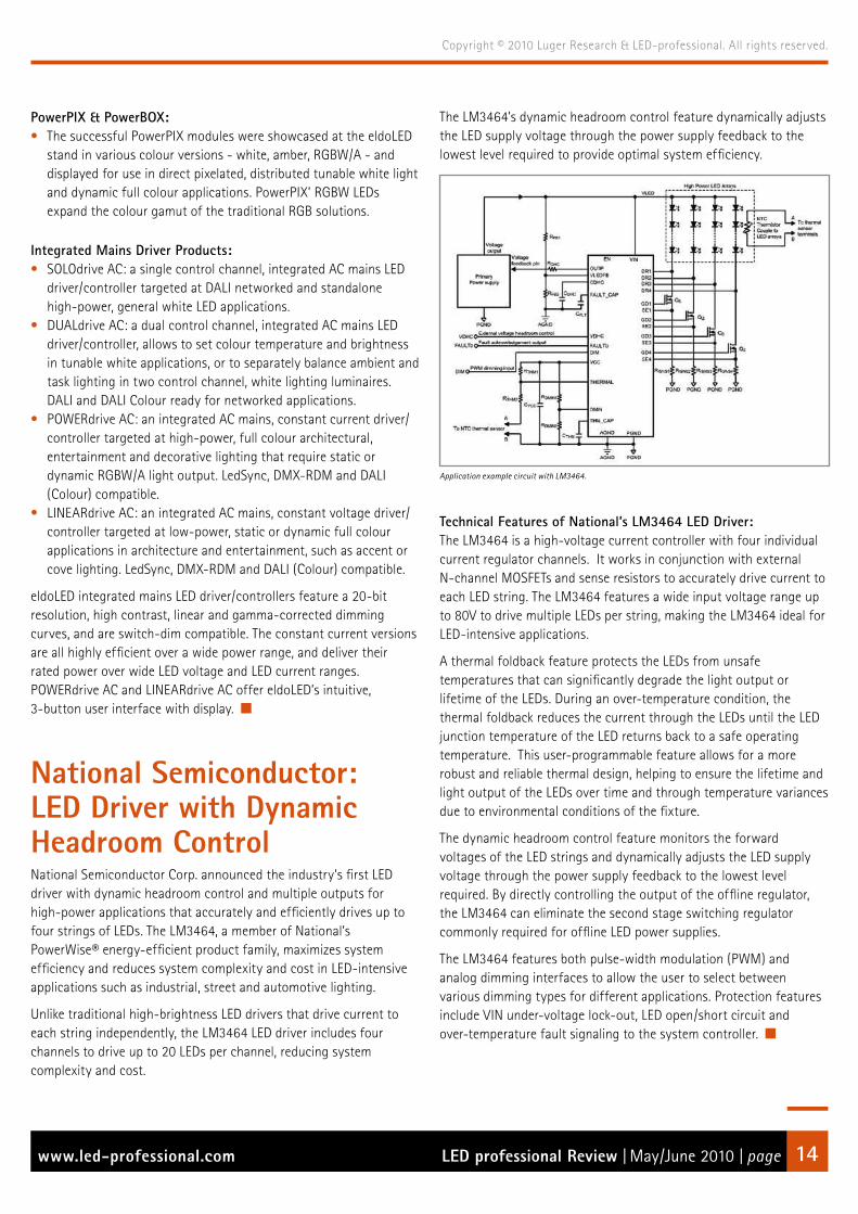
National Semiconductor: LED Driver with Dynamic Headroom ControlNational Semiconductor Corp. announced the industry’s first LED driver with dynamic headroom control and multiple outputs for high-power applications that accurately and efficiently drives up to four strings of LEDs. The LM3464, a member of National’s PowerWise® energy-efficient product family, maximizes system efficiency and reduces system complexity and cost in LED-intensive applications such as industrial, street and automotive lighting.
Unlike traditional high-brightness LED drivers that drive current to each string independently, the LM3464 LED driver includes four channels to drive up to 20 LEDs per channel, reducing system complexity and cost.
The LM3464’s dynamic headroom control feature dynamically adjusts the LED supply voltage through the power supply feedback to the lowest level required to provide optimal system efficiency.
Application example circuit with LM3464.
Technical Features of National’s LM3464 LED Driver:The LM3464 is a high-voltage current controller with four individual current regulator channels. It works in conjunction with external N-channel MOSFETs and sense resistors to accurately drive current to each LED string. The LM3464 features a wide input voltage range up to 80V to drive multiple LEDs per string, making the LM3464 ideal for LED-intensive applications.
A thermal foldback feature protects the LEDs from unsafe temperatures that can significantly degrade the light output or lifetime of the LEDs. During an over-temperature condition, the thermal foldback reduces the current through the LEDs until the LED junction temperature of the LED returns back to a safe operating temperature. This user-programmable feature allows for a more robust and reliable thermal design, helping to ensure the lifetime and light output of the LEDs over time and through temperature variances due to environmental conditions of the fixture.
The dynamic headroom control feature monitors the forward voltages of the LED strings and dynamically adjusts the LED supply voltage through the power supply feedback to the lowest level required. By directly controlling the output of the offline regulator, the LM3464 can eliminate the second stage switching regulator commonly required for offline LED power supplies.
The LM3464 features both pulse-width modulation (PWM) and analog dimming interfaces to allow the user to select between various dimming types for different applications. Protection features include VIN under-voltage lock-out, LED open/short circuit and over-temperature fault signaling to the system controller.

Photo depicts an actual installation using Cree XLamp LEDs. Cree, XLamp and the Cree logo are registered trademarks, and Lighting The LED Revolution is a trademark of Cree, Inc.
*
cr2284 LEDProf 05-06/10 Xlamp Brightest Digital AF.indd 1 4/26/10 4:55:14 PM

LED professional Review | May/June 2010 | pagewww.led-professional.com 16
Copyright © 2010 Luger Research & LED-professional. All rights reserved.
ERG Lighting: eDriver Family of LED Drivers with Universal Input and 90% EfficiencyERG Lighting, a new Division of Endicott Research Group, Inc., has introduced the eDriver family of LED power supplies for maximum efficiency in a range of solid state lighting (SSL) applications.
eDriver family of LED power supply.
The eDriver family is available in a broad range of constant voltage and constant current drivers. These driver modules are 90% efficient and fully isolated, with universal input (120V, 220V, 277V), power factor correction > 90%, and 0-10V dimming options.
eDrivers offer superior efficiency and economy and include the slimmest 100W LED power supplies on the market – up to 30% slimmer than other drivers in similar power ranges, and up to 50% smaller in total volume. All eDrivers are manufactured in the USA, with short lead times, full application engineering support and a 5-year warranty.
“It’s all about efficiency,” said Graham Upton, Vice President of Engineering. “Efficient power, size, cost and support. Endicott Research Group has been designing and manufacturing power supplies since 1979, and ERG Lighting has leveraged its expertise in LED control for solid state lighting.”
eDrivers provide the precise voltage and current critical for proper light output and SSL longevity and reliability. There is no wasted energy due to driver/load mismatch. ERG Lighting provides the exact driver that customers specify, with no unnecessary materials or functionality that would drive up the cost.
Applications for eDrivers include cove and architectural lighting, refrigeration lighting, parking and street lights, commercial and bay lighting, and more. All ERG Lighting eDrivers will have UL8750 and CE approvals and a rating of IP67. ERG is ISO 9001 certified as well as RoHS and REACH compliant.
ERG Lighting complements its eDriver family with its DRIVERsity program of custom solutions. Future options include multiple outputs, ambient light sensing, thermal feedback, a range of dimming control options, color temperature variation and custom mechanicals.
Glowled Research Claims a Novel Lens for LED LightingThe ground-breaking patented lens allows for LED-emitted light to be projected in all directions, effectively converting a point source of light (the LED package) into an envelope of light – something the basic structure of medium to high power LEDs has prevented thus far.
The lens allows for point source-emitted light to be projected in all directions evenly.
Glowled Ltd., a Washington-based, United Kingdom research and design facility and manufacturer of LED products, has filed world-wide patents for conversion of led source light into a useable envelope of light to be employed in the replacement of incandescent and CFL bulbs. Existing LED lighting has previously been based around side projection or front projection of light.
This lens technology is the first in the world and will enable lighting designers to light spaces with LEDs in fresh innovative ways. Thomas Bayat, the Founder of Glowled, said “The new lens provides excellent opportunities for LEDs to be used in direct replacement bulbs for many applications. The design of LED lighting products is currently constrained by directional lamp technology. This optical breakthrough will offer lamp designers more flexibility and scope to explore new applications.”
Glowled is focused on future research and development of LED products and Thomas Bayat would welcome approaches from partners, including existing lens manufacturers and suppliers who are interested in licensing the technology for commercial and consumer applications.

LED professional Review | May/June 2010 | pagewww.led-professional.com 17
Copyright © 2010 Luger Research & LED-professional. All rights reserved.
Khatod Featured Modular Optical System SolutionsKhatod presented its latest most innovative creation, Galileo Optical System for Power LED Lighting. By a simple combination of modules, Galileo Optical System allows customization of individual optical systems.
Khatod’s 6 by 2 Galileo optical system is just one out of a broad range of different modules for power LED lighting.
Galileo Optical System Characteristics: • An optical system combining different lenses to perform the
requested lighting beam• A wafer holding the lenses already mounted and directed
according to the requested pattern• A modular system allowing a huge possibilites for customizing the
final applications• The optics are made of PMMA and PC• The optics never come in contact either with the LEDs or with the
PCB• The optics are UV protected and guaranteed for outdoor
applications• The optics comply with UL94 specifications• Galileo Optical System is patent pending
Galileo Optical System Benefits: • The customer will receive a ready-to-use optical system according
to his requirements.• Four screws are sufficient to fix the module onto the PCB in few
minutes: the quickest mounting in the shortest time.• Available in a wide range of ready-to-use modules covering 80%
of current market requests.• The modules are available in 2 standard layouts; characteristics
and dimensions are available into the catalogue for each model.• Galileo Optical System is suitable for any application in Wide Area
Lighting.
Patented technology, innovative design, high versatile applications in Wide Area Lighting. No more need to mount and direct hundreds of single lenses in different beams in order to realize the pattern desired. A new-concept optical system, a single module, conceived and designed for immediate application.
Galileo Optical System development by Khatod included extensive work: new technology, innovative design, high optical expertise.
CeramCool LED Lamp Kit for Customer-specific LED LampsThe CeramCool LED Lamp Kit offers a flexible way to combine pre-optimized ceramic modules to create highly efficient, customer-specific LED retrofit lamps. The combination possibilities include standard LEDs, freely definable design and working elements, for individual types or complete product ranges – both large and small quantities. The kit’s standardized interface offers room for individual designs, shapes, colors or materials or for the CeramCool reflector. The latter captivates with its exquisite, indirect light along with pure ceramic quality.
The pre-optimized components of the CeramCool LED Lamp Kit can be combined as required: Sockets, base plates according to wattage, LED types based on customer specifications, reflectors and lenses.
The thermal advantage obtained, as a result of using the ceramic system, increases as demands on performance and design for lighting with LEDs grow. The kit already makes it possible to use a 10 Watt LED safely and efficiently while adhering to existing standards – a true alternative to a 60W light bulb.
The Technology:Ceramics combine electrical insulation and thermal conductivity, thus obviating the need for numerous layers of varying expansion coefficients. This boosts the long-term stability and reliability of the system and eliminates early failures caused by delamination. Efficient thermal management measurably relieves the burden on the LED. Thus, for an optimized CeramCool geometry for 4W cooling, the total thermal resistance of the ceramic assembly is not only 13% better with CeramCool Rubalit (Al2O3), but also 31% better with Alunit (AlN) than with aluminum.

LED professional Review | May/June 2010 | pagewww.led-professional.com 18
Copyright © 2010 Luger Research & LED-professional. All rights reserved.
Heat Sinks from Fischer Elektronik for Thermal Management of Sharp LEDsAlthough LEDs are clearly more energy efficient than light bulbs, which convert around 95% of current into heat and not into light, LEDs also waste a considerable amount of heat. Unlike in traditional light bulbs, this is not emitted as radiant heat but has to be dissipated through heat sinks. Without additional cooling measures, temperatures sometimes reaching well over 100°C would destroy LEDs. The dimension of the heat sinks depends on the number of the LEDs installed on the supporting substrate and the power they consume.
The high power density of modern LEDs places the greatest challenge on safe, practical heat dissipation, to achieve trouble-free operation, good luminous efficiency and a long service life.
Unlike other manufacturers, Sharp does not refer to the non-measurable junction temperature of the LED, but to the measurable temperature of the substrate. At a substrate temperature of 80°C, all Sharp LEDs have a specified service life of 40,000 operating hours.
The supporting material used by Sharp for almost all its high power LED products is high quality ceramic. This allows an efficient dissipation of heat and helps to keep the size of the required heat sinks to a minimum, thanks to its good heat conductivity properties. Although standard heat sinks are freely available on the market, the shape of cooling elements may be chosen at will as long as they guarantee the required heat dissipation. For this reason, heat sinks can also be used specifically as design elements when creating LED lamps.
Fischer Elektronik has developed concepts which are specially adapted to the constantly growing demand for LED heat sinks. In addition to many standard heat sinks which can be used to dissipate heat from the LEDs, it also offers specially modified heat sink variants for LEDs and versions which are specially adapted to individual Sharp LED products.
With its standard portfolio, Fischer Elektronik already offers a comprehensive range of different types of aluminium heat sinks which can be installed in many popular housing models used in the lighting industry.
The LEDs are fixed to the heat sink using either double-sided, heat conductive adhesive film or a suitable thermal adhesive. Additional safety can be achieved by using optional screw fittings. The standard surface finishes are anodised in black or natural.
When considering the overall system of a light, Fischer Elektronik closes an important gap, using its expertise in application-related heat management to complete Sharp’s LED partner network.
LED professional Review | May/June 2010 | pagewww.led-professional.com 20
Copyright © 2010 Luger Research & LED-professional. All rights reserved.
Event Reports
Light+Building Review> Arno Grabher-Meyer, LED professional
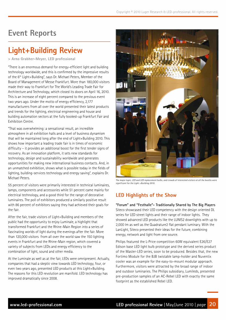
“There is an enormous demand for energy-efficient light and building technology worldwide, and this is confirmed by the impressive results of the 6th Light+Building”, says Dr. Michael Peters, Member of the Board of Management of Messe Frankfurt. More than 180,000 visitors made their way to Frankfurt for The World’s Leading Trade Fair for Architecture and Technology, which closed its doors on April 16, 2010. This is an increase of eight percent compared to the previous event two years ago. Under the motto of energy efficiency, 2,177 manufacturers from all over the world presented their latest products and trends for the lighting, electrical engineering and house and building automation sectors at the fully booked-up Frankfurt Fair and Exhibition Centre.
“That was overwhelming: a sensational result, an incredible atmosphere in all exhibition halls and a level of business dynamism that will be maintained long after the end of Light+Building 2010. This shows how important a leading trade fair is in times of economic difficulty – it provides an additional boost for the first tender signs of recovery. As an innovation platform, it sets new standards for technology, design and sustainability worldwide and generates opportunities for making new international business contacts. And, in an unmatched exhibition, shows what is possible today in the fields of lighting, building-services technology and energy saving”, explains Dr. Michael Peters.
55 percent of visitors were primarily interested in technical luminaires, lamps, components and accessories while 51 percent came mainly for electrical technology, and a good third for the range of decorative luminaires. The poll of exhibitors produced a similarly positive result with 86 percent of exhibitors saying they had achieved their goals for the fair.
After the fair, trade visitors of Light+Building and members of the public had the opportunity to enjoy Luminale, a highlight that transformed Frankfurt and the Rhine-Main Region into a series of fascinating worlds of light during the evenings after the fair. More than 120,000 visitors from all over the world saw the 150 lighting events in Frankfurt and the Rhine-Main region, which covered a variety of subjects from LEDs and energy efficiency to the combination of light, sound and other media.
At the Luminale as well as at the fair, LEDs were omnipresent. Actually, companies that had a skeptic view towards LED technology, four, or even two years ago, presented LED products at this Light+Building. The reasons for this LED revolution are manifold. LED technology has improved dramatically since 2008.
The major topic, LED and LED replacement bulbs, and crowds of interested visitors at all the booths were significant for the Light +Building 2010.
LED Highlights of the Show
“Forum” and “Festhalle”- Traditionally Shared by The Big Players Siteco showcased their LED competency with the design oriented DL series for LED street lights and their range of indoor lights. They showed advanced LED products like the LUNIS2 downlights with up to 2,000 lm as well as the Quadrature2 flat pendant luminary. With the LanLight, Siteco presented their ideas for the future, combining energy, network and light from one source.
Philips featured the L-Price competition 60W equivalent E26/E27 Edison base LED light bulb prototype and the derived series product of the Master-LED series, soon to be produced. Besides that, the new Fortimo Module for the BJB twistable lamp-holder and Nuventix cooler was an example for the easy-to-mount modular approach. Furthermore, visitors were attracted by the broad range of indoor and outdoor luminaries. The Philips subsidiary, Lumileds, presented pre-production samples of an AC-Rebel LED with exactly the same footprint as the established Rebel LED.

LED professional Review | May/June 2010 | pagewww.led-professional.com 21
Copyright © 2010 Luger Research & LED-professional. All rights reserved.
PHILIPS’ new Master-LED bulb, offering warm white light with over 800 lumens at 10 W, is directly derived from the development for the L-Price competition.
New advanced Fortimo Module for the BJB twistable lampholder with Nuventix cooler and simplified reflector mounting opportunities .
Zumtobel tended to show technical lighting with LED, as featured in the LED downlight PANOS Infinity, and the feasibility of OLED luminaries in an office installation. Their subsidiary, Tridonic, also showed OLED modules, as well as their range of LED modules. They highlighted the brand new Stark module, a Fortimo equivalent with high efficiency, CRI and tunable from CCT 2700 K to 6500 K, with a newly developed driver/supply. LEDON Lamps, the newly founded subsidiary, specialized in LED replacement lamps, presented a pre-production sample of a highly efficient 60W equivalent and a whole range of high quality replacement lamps of different form factors.
Elaborate booth concepts, spectacular and impressive colour and lighting designs were attracting the visitors all over the show.
Tridonic’s Starck Module offers adjustable CCT from 2700 to 6500 K.
Osram highlighted their PrevaLED module, expecting the chosen concept to establish a new standard for modular LED systems. The OLED pavilion inspired technicians as well as lighting designers. The new technology was combined with Osram’s vision of future lighting design and architecture.
Presentation of the abilities of the new PrevaLED modules.

LED professional Review | May/June 2010 | pagewww.led-professional.com 22
Copyright © 2010 Luger Research & LED-professional. All rights reserved.
Hall 5.0, and The Agora - The “Outdoor Lighting Boulevard”Apart from Thorn, Hess, Hella and Ragni, numerous other companies presented interesting LED products for street lighting. The improvements in LED technology also pushed the number of LED street lights with high lumen output and remarkably competitive solar street lights.
Improved efficiency and lumen packages also trigger Solar LED street lighting business.
Ruud Lighting presented their versatile new flagship, the FP-100, designed by Ferrara Palladino e Associati. Hidden inside the booth they also had an interesting new design-study of a modular street light in its early stage, before production. Schreder attracted visitors with their Pininfarina design concept for an OLED outdoor lamp and other design-oriented outdoor luminaires. Ewo GmbH showcased a 1600W powered area flood light, based on their DS31 LED-system modules, which illuminates an area of 100 x 100 meters with 20lx.
A selection of outdoor lights for different applications, from walkways to autonomous solar street lights, were on display at the Agora.
Powerful 1,600W LED panel for area lighting or floodlight applications.
Hall 4 - The Center of LED ComponentsMost of the renowned LED and array LED manufacturers like Avago, Bridgelux, Citizen, Cree, Cooper, Edison Opto, Everlight, GE, Nichia, Seoul Semiconductor, Sharp or Toshiba presented their portfolios with various new products. Verbatim and LG to name some of the newcomers in the LED lighting business, were present with very attractive products. Cree caused a stir with the announcement of the new XP-M package, with an efficiency of 160 lm/W for cool white LEDs.
Like many other LED manufacturers Cree offers different enduser products, like the PAR 38 replacement lamps.
Toshiba’s 100W equivalent prototype warm white LED bulb with more than 1600 lm at 20W, attracted a good number of visitors. Citizen focused on their range of highly efficient, high CRI, warm white products that provide MacAdam 3. Seoul Semiconductor announced the mass production of their 100 lm/W Acriche and their success in achieving 150 lm/W as a further step. Everlight showed the brand new 3W Shuen High Power LED with up to 170 lm when running at 700 mA and the expansion into the LED system business with luminaries. Sharp’s new “DoubleDome” allows lighting without a secondary lens, and the MiniZeni offers performance similar to the well established Zenigata.
A water resistant LED module for outdoor applications from newcomer LG.

Distribution is today.Tomorrow is EBV!
Thanks to LED Technology from EBV Elektronik
The bright & creative ideas of lighting architects would often dim & fail in the past because of technical difficulties or com-mercial constraints.
LEDs now make it possible to create a whole new world of lighting. They also provide much more effective lighting than conventional sources while consuming much less energy. All of this, and a service of up to 100,000 hours. However, to get the best from LEDs, you need the right partner with
the appropriate expertise and the ideal product range. This is where EBV excels. EBV Elektronik is the leading specialist for optoelectronics technology in EMEA’s semiconductor distribution.
Our experienced application experts, who concentrate solely on the use of LED technology in lighting, will offer you full support in turning your ideas into reality. Interested? Simply e-mail: [email protected]
www.ebv.com

LED professional Review | May/June 2010 | pagewww.led-professional.com 24
Copyright © 2010 Luger Research & LED-professional. All rights reserved.
Bridgelux offered their Array LEDs as easy to handle modules, the HelieonTM, now developed in cooperation with Molex. GE, Cooper, Toshiba and LG are following this trend as well, and presented their methods for easy-to-handle LED modules. Future Lighting’s approach to modular systems is the SimpleLED program, a broad portfolio of light engines which consists of LEDs on a board, with the option of a secondary optics and an onboard connector.
Verbatim is focusing entirely on the replacement market with their products that use UV/purple LEDs to produce the primary light which is converted to high CRI white light.
In this hall, other components like cooling systems, drivers, optics or providers of mounting systems, were also present. Just to name a few:
Ceramtec announced the availability of the CeramCool LED Lamp Kit that simplifies thermally reliable manufacturing of MR16 form factor based products. Nuventix is counting on the modular approach and showcased their range of improved coolers, now using half the power of the last generation while providing the same performance. Tyco supports the LED industry with its LED sockets, like the recently announced Type CM, for easy integration of the new Cree XLamp® MP-L™ multichip LED.
LEDIL, Carclo and Kathod showed their abilities to provide custom solutions in addition to their standard repertoire of LED secondary optics. Reflector manufacturers also discovered LEDs to be a relevant business since array LEDs captured a significant part of the solid state lighting market. Companies like Jordan now offer reflectors for LED downlights and different LED modules like the Fortimo, the Xicato or the Helieos module.
LED system providers, companies that offer LED modules from linear strip lights to LED panels, on top of complete solutions, like lamps and installations showcased their skills as well. NeoNeon featured the new water resistant linear high voltage LED rope with the unique ability to be driven without a driver from a length of a few centimeters up to 100 meters. A complete series of LED replacement lamps was also presented.
NeoNeon’s AC driven water-sealed flexible LED rope.
Xleds and Fawoo each introduced their high quality indoor and outdoor lamps and luminaires. Traxon/e:cue highlighted the newly developed facade modules and their new controls and driver series. eldoLED was proud to present the new series of directDrive AC off-line LED drivers. LED Linear - nomen est omen - presented their broad range of advanced and highly efficient LED products dedicated to linear lighting applications.
Traxon’s highlights wer the stainless steel LED facade modules and LED glass panels.
NOVALED is extending the range of lighting applications and solutions to specific market needs with OLEDs on metal. NEDO, the Japanese New Energy and Industrial Technology Development Organization, showed OLED products, based on modules, which were developed by Panasonic and NEC. Blackbody showcased a range of impressive OLED luminaries designed by Stark, C+B Lefebvre and Bertrand Médas.
Detailed view on the OLED Chandelier from Blackbody.

LED professional Review | May/June 2010 | pagewww.led-professional.com 25
Copyright © 2010 Luger Research & LED-professional. All rights reserved.
Designer lamp built of OLED modules.
Hall 10 - The Asian DistrictIt was clearly recognizable that a lot of effort was put into improving product quality. Especially for China, the government initiative for energy savings and LED technology has led to a remarkable boost of the LED industry. Numerous companies are now following the trend of switching over from conventional products to LED lighting products. While two years ago replacement lamps, some modules - LED strips and bars- or street lights were the main products, at Light+Building 2010, the bigger Chinese luminary manufacturers like SUNLIT Lo Ltd., introduced LED luminaries. Companies like YONYE or OPPLE announced the introduction of LED luminaries within the next few months.
Lots of action in Hall 10, high visitor frequency especially for Taiwanese and Chinese manufacturers.
The energy saving initiative has forced other companies to follow in the footsteps of companies like Kingsun, Shenzhen Crep Optoelectronics, Beijing Lampower Photoelectric Co. Ltd. or Unilumin Group Co. Ltd. which have been known for their LED street lights for years, and start producing a broad range of LED street lights themselves. In addition to LED street lights, the above-mentioned companies produce replacement bulbs and LED light tubes and modules as well. Some manufacturers, like ZheJiang Shenghui Lighting Co. Ltd. and Shenzhen Lamp Technology Co. Ltd. concentrate on LED modules, strips and replacement bulbs.
Improvements, Tendencies and TrendsToday, warm-white LEDs have a reasonable efficiency. In practice, a system-efficiency up to 80 lm/W can be achieved - a value that would have been almost a sensation with cold white LEDs two years ago. It may be even more important to note that the color rendering index (CRI) has improved in parallel as well. A CRI >80 is standard, and a CRI above 90 is not uncommon, ending up at a CRI of 98, which is similar to halogen light.
Improved packaging technology causes lower thermal resistance and as a result compact multi-chip packages with a high lumen output of about 3,000 lm.
The Bridgelux array LED with high lumen output is used in several LED downlights.
LED and component manufacturers are making a great effort to serve the needs of the lighting industry better than in previous years. Attempts to reduce the binning issues and to assure color consistency within three or even one MacAdams ellipse are just a few examples.

LED professional Review | May/June 2010 | pagewww.led-professional.com 26
Copyright © 2010 Luger Research & LED-professional. All rights reserved.
The system approach was accepted quite readily by the industry leaders. As a result, a modular approach makes LED technology more easily accessible to smaller luminaire manufacturers and lighting designers. Adequate cooling systems, optics, drivers and supplies for most standard applications are available for the LED modules. The next step might be that the module manufacturers will agree on a common standard to make different products interchangeable. This will be a big challenge, but a first step has been taken by the founding of the Zhaga consortium.
Luminaire manufacturers have learned how to manage LEDs better. Even so, some lighting designers may criticize that the recent generation of luminaries just simulates light distribution and that only a few ideas were generated that took full advantage of the opportunities of this new light source. But in fact, for a relatively young technology, remarkable progress has been made since the last Light+Building event. One should not forget that today’s established technologies had over 50 years to evolve. There are definately some additional lessons to be learned and costs have to come down in some cases to be fully competitive with HIT or T5 fluorescent lamps. Still, a huge step forward has been made and recently manufactured products can at least be used instead of 35W HIT downlights and spotlights, as well as most fluorescent downlights, and in addition, we have the highly efficient warm white LED panels that can replace T5 panel lights.
With the new generations of LEDs, high quality shop lighting has become possible.
LED replacement lamps for incandescent bulbs were shown by all of the renowned manufacturers. Due to thermal issues, 60W equivalent LED replacement bulbs will be state-of-the-art for the coming generation of E27-base bulbs. The limits for PAR38 are at a 75W equivalent and for MR16 replacements about 35W, in as far as no active cooling is applied.
Not only LEDs have improved, but also the drivers, supplies and controls have matured. New AC mains integrated drivers and innovative controls for LED systems which have adaptable color control were presented. Driver efficiency has increased practically to the limit while prices have stayed stable or even been reduced.
OLEDs are able to softly illuminate products and artworks.
OLEDs have come out of the labs to become actual products. Of course, right now they are at the stage that LEDs were at four to six years ago: They are not competitive in price and efficiency and are even limited in manufacturing size and durability. Having said that, the offered products are suited very well for prestigious high-end projects or design oriented projects and they are real eye-catchers. All at all, manufacturers showed promising prototypes and design studies, and they proved that OLEDs are on their way to another lighting revolution. The time for mass production of OLEDs may not be ripe yet but it is definitely on its way.

For North America please contact : eldoLED America Inc. | [email protected] or +1 408 451 9333 (San Jose, USA) For other countries please contact : eldoLED Europe bv | [email protected] or +31 40 2054050 (Eindhoven, The Netherlands)
DUALdrive AC series: for dual-channel white LED lighting applications
Tune your White!
DUALdrive AC and the single-channel SOLOdrive AC are world’s most ef cient fully dimmable mains LED drivers for general white LED lighting applications. The cost-effective DUALdrive AC is DALI, DALI Colour and 0-10V compatible, and also lets you dim light output over a momentary light switch. DUALdrive’s two control channels allow you to set colour temperature in tunable white applications, or balance ambient and task lighting in two control channel lumi-naires. Its maximum output power is available over a wide LED voltage and LED current range, making it the perfect companion for dual-channel white lighting applications.
For more information, please visit www.eldoled.com/dualdrive
Features & advantages:• 0-10V, DALI and DALI Colour compatible• Dimensions: 388 x 42 x 30 mm / 15.28 x 1.65 x 1.18 in. • Input voltage range: 100 - 277 VAC • Power output: 100W • LED output current setting via LEDcode • Highly ef cient (90%) over a wide power range • Integrated mains LED driver/controller simpli es setup and installation
DUALdrive AC:the most ef cient, fully dimmable, tunable white LED driver

LED professional Review | May/June 2010 | pagewww.led-professional.com 28
Copyright © 2010 Luger Research & LED-professional. All rights reserved.
New Era for LEDs in Lighting> Alan R. Mills PhD., LED professional
A new era for the LED and LEDs in lighting could be opening up this year with abundant evidence from record industry exhibit attendances approaching 3,000 at the “Strategies in Light” event. The exhibits provided a large increase in the number and type of light engines and luminaires being offered that can be used in a wide range of solid-state lighting applications, forming the basis for rapid future growth. Even after a poor first quarter in 2009, most high brightness LED (HBLED) markets returned to growth for the final three quarters supported by LED back lighting unit (BLU) markets, for mobile displays and by SSL applications in the general lighting segment. Thus, LED cellphone, auto and sign markets were lower but some LED market segments were still exhibiting healthy growth considering the poor global economic conditions in early 2009. Notable in LED application papers were the large number of LED lighting projects now installed and operating worldwide. Industry forecasters such as the iSuppli and Gartner companies are expecting renewed growth for the largest LED market (cellphones) in 2010 and onward, with even higher growth rates for the smart phone segment.
The general lighting market continued to grow, but the LED-LCD TV segment demonstrated exceptional potential, due in part to Samsung’s recent market initiative to rapidly expand its LED-LCD TV technology. With its new standardized LED TV BLUs being suitable for both TVs and PC monitors, and with a wide range of new TV models, Samsung is claiming a major market share in the TV segment (about 90%) and at the same time is stimulating competitors such as Hisense (China), JVC, LG, Sharp, Sony and Vizio (mainly a US vendor) to also expand their range of LED-LCD TVs. Each of these LED TVs, that use less power than the present cold cathode fluorescent (CCFL) BLU models, will contribute to lower energy demands in the future. High growth rates are forecast for TV BLUs with 50% penetration by 2013 plus a 90% LED penetration being forecast for notebooks in 2011 (in a total market of about 200 million units). Since 2007, medium power white LEDs have become the preferred BLU light source (over RGB LEDs) and some forecasters are indicating a possible shortage in supply of LEDs and materials in the near term, especially since some manufacturer’s LEDs do not meet the high specifications required for TV BLUs. However other factors such as the increasing rate of new LED tool installation could minimize this situation.
Jed Dorsheimer, a Principal Analyst from Canacord Adams, has estimated that if (or when) all TVs use LED BLUs, a tripling of today’s LED capacity would be needed. Without exceptional additions to capacity, Jed thought that there could be LED under capacity
beginning in 2010, which could expand to a 70 billion LED deficit by 2012. However, some leading LED manufacturers already have capacity expansion plans in progress, such as a 3x for Cree Inc., a 2x for Philips’ Lumileds. Samsung, which is in the process of acquiring about 100 LED reactors, has committed to an even greater degree of expansion. With near term order books estimated to total about 300 reactors, the outlook for the LED tool makers also looks good and the postulated future shortages may be avoided, but even more reactors will be required to meet the general lighting market LED needs, which is forecast to reach $80 billion by 2020.
In support of Samsung’s thrust into LED TVs, Jung Kyu Park, the director of BLU development at Samsung LED Co. Ltd., recently predicted that the LED BLU cost factor will only be 1.4 times that of a CCFL BLU in 2010, down from 6x in 2005. In addition, he reported that the cost per LED lumen will have fallen to less than 200 Korean Won per Watt by 2015 (about US$0.175 at 1140 Won to the dollar). At the same time, commercial LED output efficiency will have increased by about 30% to 200 lm/W further contributing to lower TV power use and enabling lower prices for the customers. Other benefits also accrue from LED use, such as an improved colour gamut and very thin or slim line TVs, but vary with the use of edge or direct back lighting formats. Samsung’s projected HBLED market segments for 2010 and their growth rates are reproduced in Table 1. During the last five years, the average HBLED selling price has declined about 11% per year as their production volumes have increased about 22% per year. These changes are some of the reasons for a 200 billion LED production year forecast for 2014 and for some LED-TV BLU forecasts to be as high as 40 million units in 2010 (see table 1).
In 2009, mobile phone unit sales were lower although smart phones still showed limited growth. Bob Steele, from Strategies Unlimited, has reported the overall 2009 LED market growth at about 5% to $5.3 billion although the large number of LEDs sold by weight are not included, a unit figure that may exceed the number of specification die (or 50 billion plus). The two highest growth rates were reported for medium power (up 152% from a low 2008 base) and high power LEDs, up 23%. The use of LEDs in autos expanded in 2009, but the market volume was lower by about 20%, because of the lower levels of car production. Bob also reported that the general lighting market continued to grow even in the weak economy, since many companies are now introducing new LED luminaires, a factor that probably accounted for the record attendance at the 2009 LightFair exhibition. With commercial LED outputs such as those just reported in the 130-140 lm/W range by Cree Inc. plus R&D outputs of 205 lm/W by Cree and 249 lm/W by Nichia, luminaires with external outputs in excess of 100 lm/W can now be manufactured, a key factor that will increase market acceptance of LED luminaires and enable a future increase in
Application TV BLU Notebook Signage Cars Lighting Mobile OtherMarket Size 1,514 432 636 1,146 800 1,871 1,264
CAGR (%) 64 34 4.5 12.2 40.3 -3.5 16.2
Table 1: 2010 HBLED Market (US$ millions) and growth rate by application (Source, Samsung).

LED professional Review | May/June 2010 | pagewww.led-professional.com 29
Copyright © 2010 Luger Research & LED-professional. All rights reserved.
market growth to 32% from 24% in 2009 and higher growth rates from 2010 onward. Other drivers for LED use were LED functionality (e.g. direction and controllability), the above noted efficiency increases, cost of ownership values and government regulations. Bob is forecasting an overall HBLED market growth rate of 53% to $8.2 billion for 2010, the highest growth rate since 2003. Unfortunately, some commercial LED products are still demonstrating poor market performance and by reputation could impede even higher growth rates.
Government support for LED general lighting was indicated by expansion of the US Energy Star programme, where the DOE and the EPA have expanded LED and luminaire testing to provide additional backing for residential lighting fixtures (luminaires), light specifications and consumer acceptance. This support will be part of the EPA/DOE 2010 Program Plan and will include rules to recognize cost effectiveness and identify the top 25% most efficient LED luminaire models, irrespective of the technology being used. This Energy Star Program should go a long way toward improving LED luminaire quality and future consumer acceptance. Rudi Hechfellner, the Director of Applications at Philips Lumileds, provided additional insight into LED lamp reliability by pointing out in his analysis that LED luminaires are only as reliable as the weakest link in the package. This can include solder joints, lens failures, poor heat sinking, luminaire maintenance and mechanical failures, but rarely is catastrophic failure due to the LEDs. Only by measuring the reliability of each part of the system can the luminaire lifetime be accurately estimated and tuned so that all components can last for similar periods of time. The 2010 Light Strategy conference provided a good cross section of the industry progress and excellent technical and market data to support the continuing growth and the healthy future often projected for the LED. Continuing US Government support for LEDs is again evident from the latest release of new Energy Star requirements.
In a recent market review and forecast for LED luminaires by Vrinda Bhandarkar from Pennwell Publishing, Vrinda proposes that convergence of the prior lighting technologies (lamps, ballasts and fixtures) is taking place in the modern LED or fluorescent luminaire. In this new era, the LED, the power supply, optics, heat controls and the fixture can be combined with remote controls and their flexible form factor to create the best potential to satisfy a wide range of efficient lighting applications such as portable, globes, MR-16s, decorative and linear fluorescent. LED luminaires, with their present outputs in excess of 100 lm/W, are now well placed to replace some fluorescent lamps and incandescents that will have been phased out in 10 countries by the end of 2010 and these will be eliminated in Canada and the European Union in 2012 and the USA in the following two years. Several key factors of LED luminaire production have yet to be optimised including optical design, mass production efficiencies, component interfaces, the ability of existing distribution channels to accommodate fast changing LED technology and a lack of worldwide standards. As the restrictions associated with these factors are eliminated they will contribute to higher efficiencies, lower costs and increasing market shares during the next five-year period. However,
these factors have not slowed market growth too much since Vrinda forecast the solid state luminaire market to be about $3.9 billion for 2010, growing to almost $14 billion in 2013. At this time the three largest LED luminaire market segments will be replacement lamps, commercial lighting and architectural use. Although LED lighting has been a disruptive technology for the lighting industry, its benefits are leading the way to a multi-billion dollar growth industry for the foreseeable future.
Strategies in Light meeting again provided abundant evidence for the health of the LED industry and about 600 technical attendees.
Jaz does it all!!
Visit us at LED4089-10 June 2010
Universal Portable Light Meter
www.oceanoptics.eu [email protected]
Lumen
Lux
PAR
CRI
CIE
CCT
Infineon BCR 32xU/BCR 42xULow cost LED drivers for medium power LEDs
THE BCR 32XU/BCR 42XU LED DRIVERS are dedicated LED drivers for 0.3 W – 0.5 W LEDs with a maximum output current of 250 mA. They are optimized in terms of cost, size and feature set for medium power LEDs.
Key Features & Benefi ts� Output current from 10 mA up to 250 mA (adj. with external resistor )� Supply voltage of 24 V (BCR 32xU) resp. 40 V (BCR 42xU) or higher � Direct microcontroller interface for dimming (BCR 321U, BCR 421U)� Reduction of output current at high temperatures contributing to long lifetime of LEDs� Power dissipation of 1000 mW� Minimum external component count � no inductors or capacitors required� Small size SC-74 package
[ www.infi neon.com/bcr32x_lp ]
10095_INF_Anz_BCR_95x88_v02.indd 1 26.04.2010 17:59:58 Uhr
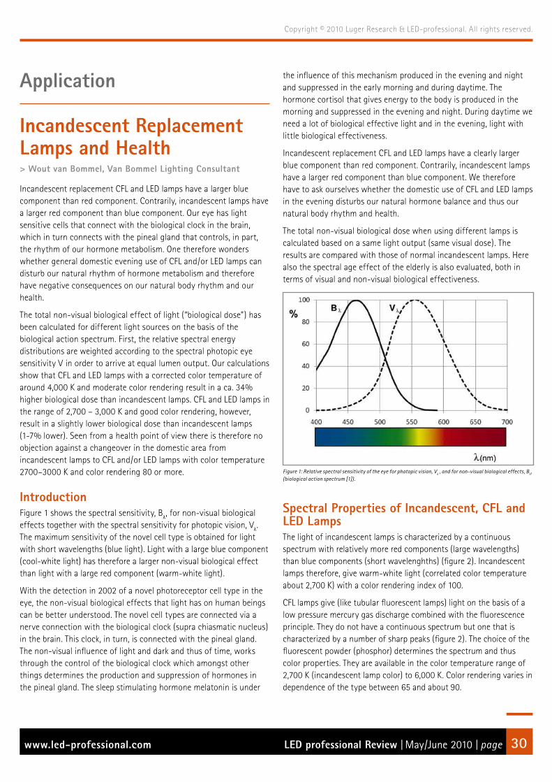
LED professional Review | May/June 2010 | pagewww.led-professional.com 30
Copyright © 2010 Luger Research & LED-professional. All rights reserved.
Application
Incandescent Replacement Lamps and Health> Wout van Bommel, Van Bommel Lighting Consultant
Incandescent replacement CFL and LED lamps have a larger blue component than red component. Contrarily, incandescent lamps have a larger red component than blue component. Our eye has light sensitive cells that connect with the biological clock in the brain, which in turn connects with the pineal gland that controls, in part, the rhythm of our hormone metabolism. One therefore wonders whether general domestic evening use of CFL and/or LED lamps can disturb our natural rhythm of hormone metabolism and therefore have negative consequences on our natural body rhythm and our health.
The total non-visual biological effect of light (“biological dose”) has been calculated for different light sources on the basis of the biological action spectrum. First, the relative spectral energy distributions are weighted according to the spectral photopic eye sensitivity Vλ in order to arrive at equal lumen output. Our calculations show that CFL and LED lamps with a corrected color temperature of around 4,000 K and moderate color rendering result in a ca. 34% higher biological dose than incandescent lamps. CFL and LED lamps in the range of 2,700 – 3,000 K and good color rendering, however, result in a slightly lower biological dose than incandescent lamps (1-7% lower). Seen from a health point of view there is therefore no objection against a changeover in the domestic area from incandescent lamps to CFL and/or LED lamps with color temperature 2700–3000 K and color rendering 80 or more.
IntroductionFigure 1 shows the spectral sensitivity, Bλ, for non-visual biological effects together with the spectral sensitivity for photopic vision, Vλ. The maximum sensitivity of the novel cell type is obtained for light with short wavelengths (blue light). Light with a large blue component (cool-white light) has therefore a larger non-visual biological effect than light with a large red component (warm-white light).
With the detection in 2002 of a novel photoreceptor cell type in the eye, the non-visual biological effects that light has on human beings can be better understood. The novel cell types are connected via a nerve connection with the biological clock (supra chiasmatic nucleus) in the brain. This clock, in turn, is connected with the pineal gland. The non-visual influence of light and dark and thus of time, works through the control of the biological clock which amongst other things determines the production and suppression of hormones in the pineal gland. The sleep stimulating hormone melatonin is under
the influence of this mechanism produced in the evening and night and suppressed in the early morning and during daytime. The hormone cortisol that gives energy to the body is produced in the morning and suppressed in the evening and night. During daytime we need a lot of biological effective light and in the evening, light with little biological effectiveness.
Incandescent replacement CFL and LED lamps have a clearly larger blue component than red component. Contrarily, incandescent lamps have a larger red component than blue component. We therefore have to ask ourselves whether the domestic use of CFL and LED lamps in the evening disturbs our natural hormone balance and thus our natural body rhythm and health.
The total non-visual biological dose when using different lamps is calculated based on a same light output (same visual dose). The results are compared with those of normal incandescent lamps. Here also the spectral age effect of the elderly is also evaluated, both in terms of visual and non-visual biological effectiveness.
Figure 1: Relative spectral sensitivity of the eye for photopic vision, Vλ , and for non-visual biological effects, Bλ, (biological action spectrum [1]).
Spectral Properties of Incandescent, CFL and LED LampsThe light of incandescent lamps is characterized by a continuous spectrum with relatively more red components (large wavelengths) than blue components (short wavelenghths) (figure 2). Incandescent lamps therefore, give warm-white light (correlated color temperature about 2,700 K) with a color rendering index of 100.
CFL lamps give (like tubular fluorescent lamps) light on the basis of a low pressure mercury gas discharge combined with the fluorescence principle. They do not have a continuous spectrum but one that is characterized by a number of sharp peaks (figure 2). The choice of the fluorescent powder (phosphor) determines the spectrum and thus color properties. They are available in the color temperature range of 2,700 K (incandescent lamp color) to 6,000 K. Color rendering varies in dependence of the type between 65 and about 90.

LED professional Review | May/June 2010 | pagewww.led-professional.com 31
Copyright © 2010 Luger Research & LED-professional. All rights reserved.
Incandescent replacement LED lamps function on the basis of light generation in semiconductor material combined with the fluorescence principle. In the semiconductor itself, blue light with a narrow spectral band around 450 nm is generated. Part of this light is transformed in a more or less continuous spectrum in the shorter wavelength area*. With cool-white LEDs (ca. 4,000 K) the blue peak in the spectrum at ca. 450 nm is still pronounced (Figure 3). With warm-white LEDs of a color temperature of around 2,700 – 3,000 K this peak is reduced and the red component increases.
Figure 2: Relative spectral energy distribution (E) of an incandescent lamp (GLS) and a typical example of a CFL lamp with color temperature 2700K together with the relative spectral sensitivity of the eye for photopic vision, Vλ, and for non-visual biological effects, Bλ, (biological action spectrum).
Figure 3: Relative spectral energy distribution (E) of an incandescent lamp (GLS) and a typical example of an LED lamp with color temperature 2700K and one with color temperature 4000K together with the relative spectral sensitivity of the eye for photopic vision, Vλ , and for non-visual biological effects, Bλ, (biological action spectrum).
Non-visual Biological DoseThe total non-visual biological effect of light (biological dose) can be calculated from the spectrum of a light source and the non-visual biological action spectrum as determined by Brainard on the basis of melatonin suppression during the night [1]. In order to get a correct comparison for different light sources, this dose has to be calculated
on the basis of light sources giving the same lumen output**. For this purpose the total lumen output is calculated from the relative spectral distributions according to:
LumenOutput (lamp) = ∑ (Eλ (lamp) * Vλ)
Next, all spectral energy values of a lamp are scaled to give a same lumen output according to:
Eλ (lamp, same lumen output) = Eλ (lamp) * LumenOutput (GLS) / LumenOutput (lamp)
Figure 4 shows the energy spectra of the incandescent lamp (GLS) and the two LED lamps on the basis of the same photopic lumen output. For all other lamps taken into account, a similar calculation has been made.
Figure 4: Relative spectral energy distribution (E) on the basis of the same lumen output of an incandescent lamp (GLS) and a typical example of the LED lamp with color temperature 2700K and one with color temperature 4000K together with the relative spectral sensitivity of the eye for photopic vision, Vλ , and for non-visual biological effects, Bλ, (biological action spectrum).
The “same lumen output spectra” are subsequently used to calculate the total relative biological dose according to:
Biological Dose (lamp) = ∑100 * (Eλ (lamp) * Bλ) / ∑ (Eλ (GLS) * Bλ)
Table 1 gives the values of the biological dose for the different lamps relative to the dose of an incandescent lamp.
Visual dose basis V (%)
Biological dose basis B (%)
Biological dose basis Rea
et al (%)
Incandescent lamp GLS 100 100 100
Halogen lamp 100 130,5 122,7
LED 2700 K, Ra 80 100 99,0 101,8
LED lamp 2850 K, Ra 90 100 92,9 100,0
LED lamp 4000 K, Ra 65 100 133,8 137,0
CFL compact lamp 2700 K, Ra 80 100 99,1 104,7
CFL compact lamp 4000 K, Ra 80 100 134,1 130,1
Table 1: Total visual dose (lumen output) and biological dose (%) relative to that of an incandescent lamp at a same lumen output.
* Latest developments show that it is possible to produce in the semiconductor material itself directly white light so that phosphor powder is not needed. This development has not been taken into account in our present analysis.** Since this often is not done in analysis described in the popular press, we often see wrong conclusions there solely based on the relative high peak values around the 450 nm area of LED lamps.

LED professional Review | May/June 2010 | pagewww.led-professional.com 32
Copyright © 2010 Luger Research & LED-professional. All rights reserved.
Research has shown that Abney’s law of additivity that holds for visual effects is not completely valid for the non-visual biological effects [2, 3, 4]. This means that the above given method to calculate the biological dose is not necessarily fully correct. The expectation however, is that deviations because of this are not large. Rea et al [5] published a hypothesis in which they explain the non-additivity through an interaction of the cones, rods and noval photoreceptors in the retina. On the same basis they determined an alternative non-visual biological action spectrum. We have calculated the biological dose also based on this action spectrum and also given in table 1 and shown as a graph in figure 5.
Figure 5: Total visual dose (lumen output) and biological dose (%) relative to that of an incandescent lamp at a same lumen output.
The conclusion is that the biological dose with the use of warm white CFL and LED lamps of approx. 2,700 K – 3,000 K and good color rendering is the same or smaller than the dose obtained when using incandescent lamps. Cool white CFL and LED lamps of about 4,000 K result in a higher biological dose. It is interesting to note that use of halogen lamps, results in a clearly higher visual dose than incandescent and CFL and LED lamps of 2,700 – 3,000 K.
Spectral Age EffectsThe clear crystalline eye lens turns yellowish with growing age. Figure 6 gives the transmission of the eye lens for the age group of 60 - 69 years relative to that of the age group of 20 - 29 years in dependence of wavelength. This spectral age effect has an influence on both the visual and biological dose. Based on the equal light output lamp spectra the reduction in visual and biological dose for 65 year old persons relative to 25 year old persons has been calculated. Table 2 gives the results and figure 7 displays the according graphics.
The more important effect is the lower visual dose with growing age, which in turn has a negative consequence for the visual possibilities of the elderly. The reduction is least with the incandescent lamp (7%). With the other lamps the reduction, for color temperatures smaller than 3,000 K, varies from 21 to 38% and for color temperatures around 4,000 K from 45 to 48%. With the use of incandescent, CFL, and LED lamps of ca. 2,700–3000 K the reduction of the biological dose is stronger than the reduction of the visual dose. This means that compensation for the visual reduction by using higher output lamps has no negative consequences on the final biological effect.
Figure 6: Transmission of the eye of 65 year old compared to that of a 25 year old persons, T65/T25, in dependence of the wavelength.
Visual dose
(%)
Biological dose
(%)25 yr. 65 yr. 25 yr. 65 yr.
Incandescent lamp GLS 100 92,9 100 64,1
Halogen lamp 100 79,1 130,5 105,0
LED 2,700 K, Ra 80 100 64,6 99,0 60,8
LED lamp 2,850 K, Ra 90 100 62,2 92,9 51,3
LED lamp 4,000 K, Ra 65 100 52,2 133,8 101,4
CFL compact lamp 2,700 K, Ra 80 100 55,3 99,1 51,4
CFL compact lamp 4,000 K, Ra 80 100 55,2 134,1 106,4
Table 2: Total visual and biological dose (%) of 25 and 65 year old’s relative to that of an incandescent lamp at equal lumen output (25 yrs).
Figure 7: Total visual and biological dose (%) of 25 and 65 year old people, relative to that of an incandescent lamp at equal lumen output (25 yrs).
ConclusionsAs indicated earlier, the discovery of the noval light sensitive cell that is so important for the non-visual biological effects only dates from 2002. Details of the mechanism behind non-visual biological effects are still being researched. We have, for example, discussed that there probably is an interaction between this cell type and the cones and rods. As indicated, such interaction has an influence on the biological action spectrum. Future research results about this interaction and about other details of the mechanism can lead to nuances in the conclusions that are given below.
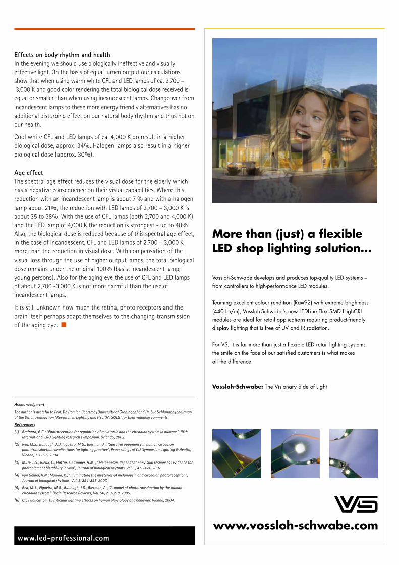
LED professional Review | May/June 2010 | pagewww.led-professional.com 33
Copyright © 2010 Luger Research & LED-professional. All rights reserved.
Effects on body rhythm and healthIn the evening we should use biologically ineffective and visually effective light. On the basis of equal lumen output our calculations show that when using warm white CFL and LED lamps of ca. 2,700 – 3,000 K and good color rendering the total biological dose received is equal or smaller than when using incandescent lamps. Changeover from incandescent lamps to these more energy friendly alternatives has no additional disturbing effect on our natural body rhythm and thus not on our health.
Cool white CFL and LED lamps of ca. 4,000 K do result in a higher biological dose, approx. 34%. Halogen lamps also result in a higher biological dose (approx. 30%).
Age effectThe spectral age effect reduces the visual dose for the elderly which has a negative consequence on their visual capabilities. Where this reduction with an incandescent lamp is about 7 % and with a halogen lamp about 21%, the reduction with LED lamps of 2,700 – 3,000 K is about 35 to 38%. With the use of CFL lamps (both 2,700 and 4,000 K) and the LED lamp of 4,000 K the reduction is strongest - up to 48%. Also, the biological dose is reduced because of this spectral age effect, in the case of incandescent, CFL and LED lamps of 2,700 – 3,000 K more than the reduction in visual dose. With compensation of the visual loss through the use of higher output lamps, the total biological dose remains under the original 100% (basis: incandescent lamp, young persons). Also for the aging eye the use of CFL and LED lamps of about 2,700 -3,000 K is not more harmful than the use of incandescent lamps.
It is still unknown how much the retina, photo receptors and the brain itself perhaps adapt themselves to the changing transmission of the aging eye.
Acknowledgment:
The author is grateful to Prof. Dr. Domien Beersma (University of Groningen) and Dr. Luc Schlangen (chairman of the Dutch Foundation “Research in Lighting and Health”, SOLG) for their valuable comments.
References:
[1] Brainard, G.C.; “Photoreception for regulation of melatonin and the circadian system in humans”, fifth International LRO Lighting research symposium, Orlando, 2002.
[2] Rea, M.S.; Bullough, J.D; Figueiro; M.G.; Bierman, A.; “Spectral opponency in human circadian phototransduction: implications for lighting practice”, Proceedings of CIE Symposium Lighting & Health, Vienna, 111-115, 2004.
[3] Mure, L.S.; Rieux, C.; Hattar, S.; Cooper, H.M. ; “Melanopsin-dependent nonvisual responses : evidence for photopigment bistability in vivo”, Journal of biological rhythms, Vol. 5, 411-424, 2007.
[4] van Gelder, R.N.; Mawad, K.; “Illuminating the mysteries of melanopsin and circadian photoreception”, Journal of biological rhythms, Vol. 5, 394-395, 2007.
[5] Rea, M.S.; Figueiro; M.G.; Bullough, J.D.; Bierman, A. ; “A model of phototransduction by the human circadian system”, Brain Research Reviews, Vol. 50, 213-218, 2005.
[6] CIE Publication, 158. Ocular lighting effects on human physiology and behavior. Vienna, 2004.
www.vossloh-schwabe.com
More than (just) a flexibleLED shop lighting solution...
Vossloh-Schwabe develops and produces top-quality LED systems –from controllers to high-performance LED modules.
Teaming excellent colour rendition (Ra=92) with extreme brightness(440 lm/m), Vossloh-Schwabe's new LEDLine Flex SMD HighCRImodules are ideal for retail applications requiring product-friendlydisplay lighting that is free of UV and IR radiation.
For VS, it is far more than just a flexible LED retail lighting system;the smile on the face of our satisfied customers is what makesall the difference.
The Visionary Side of LightVossloh-Schwabe:

LED professional Review | May/June 2010 | pagewww.led-professional.com 34
Copyright © 2010 Luger Research & LED-professional. All rights reserved.
The Future of OLED Lighting> Ian Ashdown, President, byHeart Consultants Ltd; Brent York, CEO, Tangenesys Consulting Ltd.
Organic light-emitting diodes (OLEDs) are currently a hot topic in the lighting industry. With major companies such as Osram, Philips, and General Electric displaying prototype products and announcing commercial availability of OLED panels for prototype lighting applications, it is difficult to ignore the industry buzz: “OLEDs are the future of lighting!”
Ten years ago, the industry buzz was, “semiconductor LEDs are the future of lighting!” Today, solid-state lighting (SSL) has become a commercial reality, and it may well overshadow fluorescent lamp technology in the future. However, industry should have learned an important lesson along the way:
People do not buy technology; they buy luminaires.
The importance of this lesson cannot be overstated. Referring to the IES Lighting Handbook, a luminaire is defined as:
Luminaire (light fixture): a complete lighting unit consisting of a lamp or lamps and ballast(s) (when applicable) together with the parts designed to distribute the light, to position and protect the lamps, and to connect the lamps to the power supply.
Architectural lighting has always been about more than just the lamp technology. People rely on the luminaire to properly distribute the light, both to provide desirable levels of horizontal and vertical illuminance, and to control visual glare. Lighting designers specify - and people buy - luminaires.
The lesson learned with solid-state lighting is that advances in LED technology were important only within the context of SSL luminaires. This applies equally to OLED technology. In particular, one needs to look beyond the technology and ask what it is that an OLED luminaire needs to do.
OLEDs in ReviewA typical OLED device consists of laminated organic thin films sandwiched between two electrodes and deposited on a glass or plastic substrate (figure 1). When a voltage is applied to the transparent electrodes, the current flow through the organic layers generates light as the electrons and holes recombine in the emissive layer.
If this looks familiar, it is because the principle of operation is identical to that of semiconductor LEDs. The transport and emissive layers are the organic equivalent of the indium gallium nitride (InGaN) thin films used in blue and green LEDs.
There are, however, important differences. While semiconductor LEDs are limited in size to roughly a Square millimeter or so, organic LEDs can (in principle) be fabricated by the Square meter using various manufacturing techniques. Moreover, the plastic substrates can be flexible.
Figure 1: Typical OLED device
Depending on the choice of organic materials for the emissive layer, OLEDs can be designed to emit any color, including white light with various color temperatures. This, in combination with high luminous efficacy and long lifetimes, reputedly make OLEDs ideal candidates for architectural lighting applications.
As seen with semiconductor LEDs, having light sources with high luminous efficacies and long lifetimes is only the beginning of the story. Lighting specialists need to consider how OLEDs will function as light sources in luminaires.
Optical CharacteristicsFrom a luminaire design perspective, luminary manufacturers are interested in the following optical characteristics of any light source:
Characteristic StandardLuminous efficacy (lm/W)Luminance (cd/m )L70 lifetime (hours) IES LM-80-08CCT (Kelvin) ANSI C78.377Colour Rendering Index (Ra) CIE 13.3-1994Chromaticity binning ANSI C78.377Unified Glare Rating (UGR) CIE 117-1995
Table 1: Light source optical characteristics.
OLED manufacturers today typically quote three parameters for their white light products: luminous efficacy (lm/W), luminance (cd/m ), and lifetime (hours). The first two are familiar, but some care needs to be taken with lifetime values.
As defined in IES LM-80-08, the rated lumen maintenance life Lp is the “elapsed operating time over which the LED light source will maintain the percentage, p, of its initial light output.” For lighting display purposes, the L50 (50% lumen maintenance) value is used, while for architectural lighting the L70 (70% lumen maintenance) value is required.
Reflecting OLED’s heritage as a display technology for television and mobile devices, many manufacturers state or assume L50 for their lifetime values. Converting these into L70 values however is easy - just divide the L50 value by two.

LED professional Review | May/June 2010 | pagewww.led-professional.com 35
Copyright © 2010 Luger Research & LED-professional. All rights reserved.
Six months ago, the state-of-the-art for commercially available white light OLED lighting panels featured 15 lm/W luminous efficacy, 1,000 cd/m2 luminance, and an L70 lifetime of 5,000 hours. However, OLED technology is advancing rapidly. For example, OLED manufacturer Visionox (www.visionox.com/en) has demonstrated prototype desk lamps featuring white light OLEDs with 40 lm/W and an L70 lifetime of 50,000 hours.
Figure 2: Visionox prototype desk lamps.
Applying Haitz’s Law (which successfully predicted that LED luminous intensities would double every 36 months), an optimist might reasonably conclude that architectural OLED luminaires are “just around the corner.” (The OLED manufacturers themselves are predicting another three to five years.) However, this begs the question: what is an OLED luminaire?
Lighting WallpaperMany OLED manufacturers do not see their products as being used as lamp replacements. In a recent interview with www.dvice.com, OLED scientist Anil Duggan of GE Research said:
“The big fantasy product that lighting designers always talk about is lighting wallpaper. Some lighting professionals want all offices and homes to have this very flexible light source. Flexible means a mechanically flexible light source that one can just paste wherever wanted and turn it on.”
The question is, does this make sense? Will lighting designers and, more importantly, consumers, accept “lighting wallpaper”? We have, after all, spent over a century designing and specifying luminaires that control the light emitted by bare lamps, mostly while shielding the lamps from direct view. Will users accept such a radically different design paradigm?
To answer this, a look back fifty years to a time when “luminous ceilings” were in vogue, can help. These consisted of white plastic diffusion panels backlit by linear fluorescent lamps. At the time, they were popular for residential kitchens and (in the movies) futuristic space stations (figure 3). Today, you will be hard-pressed to find any examples - most people do not like them.
Figure 3: Stanley Kubrick’s 200 - A Space Odyssey.
One notable exception is the Modern Wing of the Art Institute of Chicago, where the soft and essentially shadow-free lighting is well-suited for displaying sculptures and paintings (figure 4). For most applications however, lighting with directionality and shadows to define the visual environment is preferred. A typical counter example is a uniformly overcast sky. While the horizontal illuminance may be 50 to 100 times greater than what is expected for indoor environments, people often complain about the weather being “dark and dreary”.
Figure 4: Art Institute Chicago Modern Wing.
Whether OLED manufacturers can produce lighting wallpaper or luminous ceiling panels is immaterial if there is no significant market for their products.
While people may not accept lighting wallpaper or luminous ceilings, there is certainly a market to replace the millions of linear fluorescent lamp troffers in existing office buildings throughout the world. Energy-efficient OLED panels as retrofit luminaires would seem to be an ideal solution. There is, however, another problem: visual glare.

LED professional Review | May/June 2010 | pagewww.led-professional.com 36
Copyright © 2010 Luger Research & LED-professional. All rights reserved.
Visual GlareLinear fluorescent troffers are designed to limit their luminous intensity distributions at high viewing angles in order to prevent visual glare in the field of view. ANSI/IESNA RP-1, for example, specifies the maximum intensity to range from 300 cd at 65 degrees to 60 cd at 85 degrees. CIE 117 is even more specific with its Unified Glare Rating (UGR) for direct luminaires.
To quantify this issue, Lighting Analysts’ AGi32 was used to model two empty rooms measuring 24 x 24 meters with 64 1x4-foot direct linear fluorescent troffers. In the first model, used photometric data for a typical commercial luminaire, while for the second model a hypothetical 53x7-inch OLED panel with a luminance of 3,700 cd/m2 was used to produce the same horizontal workplane illuminance of 320 lux.
For the first model, the UGR values rarely exceeded 18 (“acceptable” visual glare). For the second model, the UGR value was 22 to 24 (“unacceptable” to “just uncomfortable”) throughout the floor space, regardless of viewer orientation. (Somewhat surprisingly, the intensities of the OLED panel were 283 cd at 65 degrees and 58 cd at 85 degrees, which satisfied RP-1 requirements.)
Quite simply, it is not possible to employ OLED panels as replacements for direct linear fluorescent troffers without some form of optical control to limit their luminance at high viewing angles. Unfortunately, the only way to do this without sacrificing some of the light emitted by the panels is to increase their luminance to that of T8 linear fluorescent lamps - 10,000 cd/m2.
It is possible that OLED panels can be used as light sources in suspended indirect linear luminaires, but these typically require batwing luminous intensity distributions to avoid unsightly “hot spots” on the ceiling. Past experience in designing such luminaires indicates that OLED panel luminances on the order of 10,000 cd/m2 will still be required.
Color IssuesWhite-light OLEDs typically employ different electrophosphorescent materials to generate red, green, and blue light (Figure 5). By balancing the light output from each material, the OLED manufacturer can adjust the correlated color temperature (CCT) over a wide range. To meet the expectations of the architectural lighting market, this range should be within the range of 2,700 to 6,500 Kelvin (ANSI C78.377).
The problem with this approach is that each electrophosphorescent material has a different L70 lifetime, with blue OLED materials typically half that of red and green OLED materials. As the OLED panels age, there will inevitably be significant color shifts.
This is not an important issue for OLED television displays, as each pixel color is driven independently by the video controller. All that is required is to occasionally adjust the display color balance. For white light OLED panels however, there is no color control. As a result, the panels may exhibit unacceptable color shifts long before their L70 lifetime is reached. (A rough calculation indicates that this may happen after a lumen depreciation of only two to three percent.)
Figure 5: Typical white light OLED spectrum.
What constitutes an “unacceptable” color shift? ANSI C78.377 permits white light LEDs to have variations in chromaticity within the limits of 7-step MacAdam ellipses. This may be compared with ANSI C78.376, which specifies smaller 4-step MacAdam ellipses for linear and some compact fluorescent lamps.
ANSI C78.377 implicitly recognizes the technical difficulties of chromaticity (“color”) binning for semiconductor LEDs, which is why it allows 7-step MacAdam ellipses. Seen side-by-side however, two colors that are seven MacAdam ellipses apart are easily distinguishable. If OLED panels are intended to be viewed directly, then 4-step MacAdam ellipses will likely define the limits of acceptable color shifts.
One potential solution to the problem of color shifts is to employ narrow stripes of red, green and blue OLED materials with separate electrical drivers for each color and optical feedback, similar to what is done with high-end SSL luminaires with RGB LEDs. However, this takes away from the simplicity of OLED panels.
ConclusionRegarding the architectural lighting requirements for future OLED-based luminaires, visual glare and color shifts with aging are important, but not the only issues. There are other factors that should be taken into account, for example CIE Colour Rendering Indices (CRI) and luminance uniformity. Low voltage power supply and thermal issues must be addressed, too. (Claims of “no heat” for OLEDs, notwithstanding whatever electrical power that is not converted to light is necessarily converted to heat.)
While the lighting industry is encouraged by the ongoing development of OLED technology, there is a risk that the OLED manufacturers may not fully appreciate the needs of the architectural lighting industry. Reasonable doubt is advisable that the availability of lighting wallpaper and luminous ceiling panels will result in a paradigm shift towards radically different lighting designs. The technology to create such designs has been available for over half a century, and they are not at all popular.

LED professional Review | May/June 2010 | pagewww.led-professional.com 37
Copyright © 2010 Luger Research & LED-professional. All rights reserved.
Another concern is that if OLED panels are to be employed as linear fluorescent lamp replacements, their luminance will have to be improved from the current 1,000 cd/m to perhaps 10,000 cd/m2 - a ten-fold improvement. At the same time, the L70 lifetimes will have to be improved five-fold or more. Luminance and lifetime are interdependent characteristics of OLEDs, and so these requirements will likely present a considerable challenge to the OLED manufacturers.
Luminaire designers should also be very much concerned about potential color shifts as the white light OLED panels age. Little relevant discussion of this topic can be found in the OLED research literature, but it is a critical issue that has to be addressed.
So what is the future of OLED lighting? Although one remains hopeful, it seems that no-one can honestly tell. Based on over one decade of experience in SSL research and development, some concerns have to be expressed. It is absolutely necessary that the architectural lighting industry, including everyone from lighting designers to luminaire manufacturers, will discuss these issues and communicate with the OLED manufacturers.
Whatever one may say, one statement is absolutely true: People do not buy technology; they buy luminaires.
References:ANSI. 2001. Specification for the Chromaticity of Fluorescent Lamps, ANSI C78.376-2001.ANSI. 2008. Specification for the Chromaticity of Solid State Lighting Products, ANSI_NEMA_ANSLG C78.377-2008.ANSMES. 2004. Office Lighting, ANSI/IESNA RP-1-04.CIE. 1995. Method of Measuring and Specifying Colour Rendering of Properties of Light Sources, CIE 13.3-1995.CIE. 1995. Discomfort Glare in Interior Lighting, CIE 117-1995.IES. 2008. Approved Method: Measuring Lumen Maintenance of LED Light Sources, IES LM-90-09.Navigant. 2009. Multi-Year Program Plan FY09-FY15: Solid-State Lighting Research and Development.

LED professional Review | May/June 2010 | pagewww.led-professional.com 38
Copyright © 2010 Luger Research & LED-professional. All rights reserved.
LED High Bay Lighting> Michael Schratz, Director of Marketing, Dialight Corp.
As a company specializing in cooking oil management solutions, Frontline International is rapidly growing a “green” business in producing equipment for recycling oil as alternative renewable fuels. At the time, Frontline was in the early stages of designing a new plant facility. In their other facility, they had been using fluorescent and incandescent lighting for the assembly areas. This required a large number of fixtures to get the bright light needed for assembly operations, and energy consumption was enormous. Palazzo and his team began investigating alternative lighting options to reduce the amount of energy that would be required to light their new plant. After evaluating high pressure sodium lights, newer fluorescent technologies and LED lighting solutions, they decided that LED lighting was the optimum eco-friendly solution.
Figure 1: Frontline’s new processing facility with LED High Bays from 7 metre high ceiling.
Brighter Illumination from fewer Light FittingsAfter comparing several LED lighting solutions, Frontline chose Dialight’s DuroSite Series LED High Bay lighting fixtures for several key reasons: their robust design and construction, their high energy efficiency, hands-free minimal maintenance and low total cost of ownership over time. Frontline felt they would be ideally suited for their high-ceiling manufacturing and warehouse facilities.
With unique high 11,900 lumens per 150 Watt efficacy, these High Bay fixtures combine the latest in LED technology, precision optics and next generation thermal management practices. The fixtures are able to deliver ultra-bright clear white light uniformly across the facility’s assembly floor from a height of seven metres with CRI of 70 and CCT of 6,000 K by using a custom focused narrow circular optic. Much more efficient than traditional HID fixtures, which waste light on walls and overlap, the precise optics are the sole factor enabling the customer to reduce the number of fixtures it required.
Even though at over 1000 sq metres the new facility is approximately three times the size of its other manufacturing facility, they were able to significantly downsize the number of lighting fixtures needed in the new plant to only 59 from over 100. They now get brighter illumination with fewer lights running on far less electricity, which not only lowers energy consumption and costs but reduces their carbon footprint, as well, in keeping with their sustainability initiative.
LED Versus Metal Halide Delivered LightA delivered light target of 50 foot candles at the floor was determined, equivalent to 538 lux. Tests showed that while a 250 Watt metal halide fixture met the target initially, it could not reach it at the end of its life, so the next option was 400 Watts which over-delivered 218 fc (2,345 lx) at the start and 104 fc (1,119 lx) at the end of life. In comparison the 150 Watt High Bay LED driven at 315 mA delivered a much more efficient 86.8 fc, 934 lx, at the start and still met the customer requirements of 59 fc, or 635 lx, after 60,000 hours, achieving the full lifetime value of its Cree XPG LEDs.
Figure 2: Lumen maintenance of different light sources compared to the DuroSite LED High Bay lighting fixture.
Figure 3: Illuminance with the 150 Watt LED High Bay shows initial 86.8 fc - 934 lx (a), and after 60,000 hours 59 fc - 635 lx (b), exceeding the specification of the client regarding brightness and even light distribution over life-time.
LED lighting features & benefits• 80% lumen maintenance after 60,000 hours• 77lm/W (LM-79) certified• Significant energy savings• Instant on/off• Maintenance free• Mercury free• Superior light quality• Minimal light pollution• No heat or UV• Simple installation

LED professional Review | May/June 2010 | pagewww.led-professional.com 39
Copyright © 2010 Luger Research & LED-professional. All rights reserved.
Improving Safety, Efficiency and Environment for Employees“Our employees love the new brightly lit facility, joking that it makes the old plant feel like a dungeon,” commented Palazzo. “It was very important for us to make sure we had enough lumens to make the workplace ergonomic for our employees. The High Bay overhead fixtures are a huge improvement, providing light bright enough for assembly work at waist level and even at floor level. The ultra-bright illumination not only expedites assembly work, it also makes the work environment much safer for our workers.”
Frontline’s electrical contractors were sceptical at first of the decision to install LED fixtures, Palazzo said. “But once they saw these High Bay fixtures and started working with them, they were impressed with how quickly and easily the fixtures installed, and how bright their illumination was. In fact, they brought in light meters that verified the even distribution of clear, white high quality light throughout the facility, even in remote corners. Now they are recommending LED lighting to their other customers.”
Figure 4: Face view of the DuroSite Series LED High Bay lights.
Figure 5: Comparison of a traditional High Bay compared to the DuroSite Series LED High Bay
Maintenance-free and Long Life LED Light FittingsAnother benefit that the project initiator recognised as a pivotal reason to install the LED unit was that these High Bay fixtures are virtually maintenance free. The LED lights sustain approximately 80% lumen capacity over 60,000 operating hours and last for an average of ten years. This lifespan vastly reduces maintenance burden and equipment replacement costs in comparison to fluorescent T5s, and their maintenance staff does not have to risk injury from changing high ceiling-mounted bulbs.
Fixture Type
(compared to the DuroSite
Series LED High Bay Fixture -
150W / 60,000 h)
T5HO
Fluorescent -
6 lamps / unit
(324W)
Metal Halide
(400W)
High Pressure
Sodium
(400W)Total system wattage 389W 480W 480W
Average lamp life 30,000 20,000 24,000
Annual energy savings per unit 9,068 12,609 12,609
Lifetime relamp & maintenance
savings [£]13,237 19,856 19,856
Annual energy savings [kWh] 123,486 170,646 170,646
Annual CO2 emission reduction
[in tons]106 146 146
Table 1: DuroSite Series LED High Bay Fixture energy saving potential. The calculation is based on the system wattage of 150W and the average lamp life of 60,000 hours from the DuroSite Fixture, and the number of units that are necessary to provide the desired lumen output after 60,000 hours.*
Today, initial cost - as usual for high quality LED lighting fixtures - is about twice the price of a competing standard product, but due to a lower number of fixtures, significant energy savings and relamp & maintenance savings, a typical payback of under 2 years can be expected.
ConclusionFrontline International is dedicated to sustainability initiatives that benefit associates, customers and community - from responsible manufacturing techniques through compliance with industry standards, workplace safety, energy conservation and protecting the natural environment. They plan to use energy efficient, ergonomic LED lighting solutions, like the High Bay overhead lighting fixtures, to help them continue to achieve their “green” sustainability goals.
* All figures are typical and based on calculations provided by the United States Department of Energy.

LED professional Review | May/June 2010 | pagewww.led-professional.com 40
Copyright © 2010 Luger Research & LED-professional. All rights reserved.
Optics
Design and Manufacture of Achromatic Lenses> Christoph Gerhard, Dr. Geoff Adams and Stephanie Wienecke
In the last few years, white-light LEDs such as phosphor-based LEDs or RGB systems have become well-established light sources in a number of applications. For instance, machine vision systems, microscopes, endoscopes and vivo imaging systems in bioscience applications are based on white-light LED illumination. However, wavelength dependant variations in the refractive index of optical media mean that light of different colours is focused at different positions along the optical axis. A simple lens will therefore show clear coloured fringes occur along boundaries of the image. Thus, chromatic aberration is one of the main optical “defects” that must be controlled if a white-light LED-based optical system is to image well. This effect can be reduced by using achromatic optics in the imaging system. Most commercial optical systems contain achromatic components. This paper reviews the basics of computer-assisted design and the manufacturing of such achromatic lenses.
Design of Achromatic LensesChromatic aberration is the result of the change in refractive index, n, with wavelength. The most obvious result of this is a change in focal length, so a simple lens could be perfectly focused for the blue (as for example for a monochromatic LED) but badly out of focus for the red. This effect is also known as longitudinal chromatic aberration. There are more subtle effects, such as lateral chromatic aberration and spherochromatism, which may be important in different types of systems. When dealing with visible systems, optical designers start by assessing the performance at three suitably spaced wavelengths, conventionally the red - C (656nm), yellow - d (588nm) and blue - F (486nm) Fraunhofer lines. The change in index or dispersion varies from glass to glass. One useful measure of this is the V-value, where
(1)
For optical glasses, the V-values range from 25 to 85, the higher being less dispersive [1]. A simple one glass lens will exhibit a fractional change of focal length of somewhere between 1.2 and 4%, depending upon the material used. However, by combining elements of different powers and materials, chromatic aberration can be much reduced. Such lenses are known as achromatic. The first such, an achromatic doublet was designed by Chester Moore-Hall in the 1730’s. This consisted of a stronger positive crown glass (high V or low dispersion) and a weaker negative flint glass (low V or high dispersion) cemented together. It turns out that the exact combination of powers and V-values can be derived using simple simultaneous equations, not requiring the use of a computer.
We might think that chromatic aberration could therefore easily be corrected in white-light LED-based imaging systems. However, there are two further problems that must be overcome: Firstly there are only a limited number of glasses or other optical materials with different indices and V-values, so we may not find an exact match. Figure 1 shows a standard plot of n- and V-values for Schott glasses, one of the main five or six manufacturers.
Figure 1: n/V-value plot, so-called Abbe-diagram.
Secondly, these equations only ensure that the focal lengths are equal at the C and F wavelengths. If the index variation was linear with wavelength, then we could correct chromatic aberration for any wavelength. Unfortunately, as shown in figure 2, though monotonic, the curves are distinctly non-linear.
Figure 2: Index of refraction of three different glasses vs. wavelength.
In fact, in the visible, to obtain sufficient accuracy, we have to describe the index curves using polynomials with at least six coefficients. Given this, no glass pairs exist which will completely cure even longitudinal chromatic aberration. Thus we might expect to see secondary spectrum (i.e. focal length variation between d and C/F) of about 0.03% [2]. By using special glasses this can be reduced somewhat. The use of a third glass may help secondary spectrum if carefully chosen,

LED professional Review | May/June 2010 | pagewww.led-professional.com 42
Copyright © 2010 Luger Research & LED-professional. All rights reserved.
and some astronomical objectives and binoculars lenses are indeed of the triplet form - though this is also to allow the design to correct non-chromatic aberrations such as astigmatism.
So far we have thought about simple doublets, but in more complex imaging systems such as photographic lenses or white-light LED-illuminated microscope objectives and eyepieces, a choice of two glasses is not generally sufficient. As shown in figure 3, such systems may have four, five or more glasses - but we cannot say that this is for chromatic correction alone.
Figure 3: Glasses used in an optical system consisting of several lenses.
In such systems, there are many design parameters which link together in extremely non-linear ways to impact on overall optical performance. Given this dependency, optimisation software is an absolute essential when finding the final curvatures, separations, and glasses [3, 4]. Typically such programs will start from some initial design and then, guided by the designer, iterate and refine the design until acceptable performance is reached. Looking at such systems afterwards we may guess approximately why a particular glass has been chosen, but the exact reasons or linkages will be hidden from our sight.
Manufacture of Achromatic DoubletsFrom the final lens design, production drawings, which contain essential information on each element, are generated. For instance, glasses, radii of the optical surfaces, mechanical and optical tolerances as well as coating specifications are given by this drawing. Further assembly drawings will also be generated for each achromat.
Let‘s see how such an achromat is manufactured. Since a simple achromatic doublet consists of two singlets cemented together, we start with the simplest case - the generation of a spherical surface in a plano-convex element.
In the manufacture of optics, the production process usually starts with cutting the raw material, the optical glass, which is provided in bars, blocks or solid blanks. For this purpose, diamond-studded circular saw blades are used. The glass is cooled by an injected lubrication solvent that is injected during the cutting. In this process, cuboid blanks are generated. These blanks are then ground circular subsequently in order to create plane-parallel cylindrical blanks for lenses. Next, rotating diamond cup wheels are used to pre-grind a radius on the plane surfaces, as shown in figure 4.
Figure 4: Scheme of the pre-grinding process.
In this process, the blank is fixed on a rotating work piece carrier. By introducing a specific angle to the axes of both the carrier and the grinding tool, a defined radius is applied to the plane surface [5]. In the next step, the generated radius is precision ground by using “bowls”, i.e. moulding tools that can be covered with pellets or feature a diamond-studded surface. As shown in figure 5, the processing method is nearly the same as for pre-grinding, but involving an additional oscillation of the particular tool.
Figure 5: Scheme of the precision grinding process using pellet-covered (left) and diamond-studded moulding tools (right).

LED professional Review | May/June 2010 | pagewww.led-professional.com 43
Copyright © 2010 Luger Research & LED-professional. All rights reserved.
In some cases, such as high-precision optical surfaces, the surface is lapped. Lapping is effected by using a compound of freely floating abrasive grain, called lapping powder, and water. In this case, the moulding tool is made of cast iron.
After precision grinding, the lens surface is polished. In principle, this step can be compared to the lapping procedure. For polishing, thin leaves, e.g. polyethylene or polyurethane, are used as polish layers that are pasted in moulding tools [5]. Alternatively, a coating made of pitch can be used as polish layer. The grain size of the polishing agent, a compound of water and abrasive such as cerium oxide or aluminium oxide, must be less than some tens of microns for high-quality polishing. In this step, the final profiling of the lens surface as well as a high surface quality is performed according to the specifications given in the drawing.
The polished surfaces can then be inspected using one of two methods. Historically the surface accuracy as well as scratches and digs were controlled visually by comparing the individual lens surfaces to etalons. Alternatively the surface accuracy can be measured interferometrically.
Once the single lenses have passed the quality control and been coated with antireflective coatings, the two singlets are cemented to form the achromatic doublet, usually with a cement that is hardened by exposure to UV-light. Here, the centring error, which is the deviation of the optical axes of both lenses, is aligned to a minimum value before cementing. After this step, the edge cylinder of the achromatic lens features a wedge error in relation to its optical axis. This error is corrected by centring. For this purpose, the lens is chucked between two clamping bells and then rotated as shown in figure 6.
Figure 6: Scheme of the centring process of a single biconvex lens.
By applying a centring tool, the edge is then ground parallel with respect to the optical axis. After this step, the wedge error of the centred achromatic lens amounts to some minutes of arc or, as the case may be for high-quality centring based on laser-assisted alignment, some arc seconds. Finally, the achromatic lens must pass a further quality control before it is used in the assembly of a complete optical system.
ConclusionsThe correction of chromatic aberration is one of the most important aspects that have to be considered when designing imaging optical systems based on white-light LED sources. Here, achromatic lenses or lens groups are used. For this purpose, the wavelength-dependent refractive index of available optical materials has to be taken into account. In such design processes, sophisticated optimization software allows the development of highly-corrected achromatic systems. The final task is the manufacture of the designed optics. In each step, high machining accuracies are required since the performance of any optical component is degraded by almost any slight departure from the design values.
References:[1] Schott AG: “Optical Glass - Properties”, Schott Pocket Catalog Version 1.5 6/2003[2] W T Welford: “Aberrations of Optical Systems”, (1986), Adam Hilger[3] Th. Thöniß, G. Adams, Ch. Gerhard: “Optical System Design - Software Tools Cover Envelope Calculations to
the Final Engineering Drawings”, Optik & Photonik 2/2009, Wiley-VCH Verlag[4] N. Harendt, Ch. Gerhard: “Simulation and Optimization of Optical Systems”, LED professional Review
10/2008, Luger Research[5] J. Bliedtner, G. Gräfe: “Optiktechnologie” (2008), Carl Hanser Verlag
light measurement
We bring quality to light.
Phone: +49 89 45 49 43 0 · [email protected] · www.instrumentsystems.com
LED Test and Measurement
Measure all optical and electrical parameters of single LEDs, high-
power LEDs and LED modules in conformity to international
standards accurately and within seconds. With equipment from
Instrument Systems – the world leader in LED metrology.
Ï Luminous intensity (candela)
Ï Luminous flux (lumen)
Ï Dominant wavelength (nm)
Ï Color coordinates (x, y, z)
Ï Spatial radiation pattern
Ï Thermal behavior

LED professional Review | May/June 2010 | pagewww.led-professional.com 44
Copyright © 2010 Luger Research & LED-professional. All rights reserved.
Drivers
About PLC Reliability> Ashish Garg & Angad Singh Gill, Cypress Semiconductor Corp.
Powerline communication (PLC) technology is experiencing a period of rapid growth. PLC is finding its way into multiple applications and market segments including lighting control, solar panel monitoring, smart grid, energy metering, in-home video distribution and electric cars. The global push for energy conservation is driving the need for intelligently communicating with energy generation and energy consuming devices. PLC offers a unique no-new-infrastructure solution to meet the requirement of rapidly deploying smart energy management around the world.
Semiconductor companies have taken note of this explosive demand for PLC solutions and as of today, system designers can purchase PLC solutions from over 10 different vendors. With so many solutions to choose from, it is hard to determine a PLC implementation that really suits all needs. It is necessary to know the factors that affect the performance of a PLC implementation and the product features that can help overcome communication challenges.
Figure 1 shows a generic block diagram of any communication system. The transmitter injects signal Tx into the medium, the impedance of the medium attenuates the signal, the noise in the medium corrupts the attenuated signal, while the receiver decodes the Rx signal.
Figure 1: Block diagram of a typical powerline communication system. Impedance of the powerline attenuates the Tx signal. Noise in the line can significantly affect the reliability of communication.
Looking at the left hand side of the diagram and working to the right:
Tx Signal Strength A stronger Tx signal implies more signal power into the line: it is less prone to the corrupting effects of the noise on the powerline and also travels farther. So why not continue to crank up the signal strength of a transmitter until getting the best communication performance on the powerline? Tx signal strength is tightly controlled by organizations like FCC (North America) and CENELEC (Europe). FCC and CENELEC also regulate the harmonics injected by the main Tx signal into the powerline. The logic behind these regulations is to avoid signals from corrupting one another.
Tx signal strength also affects the power consumption of the PLC node. The more signal energy injected into the line, the more energy the node consumes.
Tip #1: One should check if the PLC solution meets the Tx signal strength requirements for the target market and if the Tx gain is configurable. Is the PLC solution compliant with standards set by FCC and CENELEC?
Tip #2: One should check how much energy the PLC node consumes to achieve the best possible Tx signal strength as required by FCC and CENELEC. Of course, less is better.
Noise Once the Tx signal has been injected into the powerline, it is left to the mercy of the noise. Noise on the powerline comes from multiple sources in varied flavors. Simplistically, there are two types of noise on the line:
• Impulse noise: Whenever a blender is switched on in the kitchen – it makes the powerline go crazy. Lots of really nasty noise is injected into the line. This is impulse noise – noise that is unpredictable and comes in bursty sequences. It is tough to design a system for unpredictable impulse noise without compromising on baud rate. More often than not, this type of noise clobbers the PLC data packets on the line.
• Continuous noise: This type of noise is usually a function of the quality of powerline installation in a neighborhood, city, or a country. Because the original idea behind powerlines was to use them to carry power, and not data, not much attention was paid to noise levels on the line. Depending on which part of the world a system operates in, powerlines can be more or less noisy.
Figure 2: Impulse noise (left) and continuous noise (right) on the powerline.
Tricks of PLC implementers to overcome the affects of noise:• Bidirectional communication: If a PLC system communicates
only one way, then there is no way for the transmitter to know whether the communication was successful. This was one of the biggest drawbacks of the original uni-directional X10 PLC technology. Whenever blenders came on in the kitchen, the bedroom light switch stopped working.

From efficiency to aging, colour, reliability and cost… Get all the information you need to start working with OLEDs
Add value to many types of light installations and broaden design capabilities through improved colour range, viewing angles and more
Interact, test and explore OLED Technology: Understand how they work and the full extent of what they can and can’t do
Come face to face with the largest and most innovative lighting designers in the world as they candidly discuss how and why they are using OLED
Get realistic predictions as to when, where and how OLEDs are going to hit the market, and what they’ll be able to do when it happens
Dr Geoff WilliamsOLED Group LeaderThorn Lighting
Oscar PeñaSenior Creative DirectorPhilips Lighting
Iain RuxtonAssociateSpeirs and Major Associates
Peter NgaiVP of Research & Development Acuity Brands lighting
Mike HackVP - Strategic Product DevelopmentUniversal Display Corporation
Gerd GüntherVice President Novaled
Dr Dietrich BertramOLED ManagerPhilips
Co-Organisers:
Gold Sponsors:
Ingo MaurerFounder & DesignerIngo Maurer
See www.oledinsider.com/lighting-design/ for the agenda

LED professional Review | May/June 2010 | pagewww.led-professional.com 46
Copyright © 2010 Luger Research & LED-professional. All rights reserved.
• Retries: In case the transmitter does not receive an acknowledgement from the receiver, then an intelligent transmitter can re-send data packets. Retries, if automatically built into the PLC implementation, can be a very powerful tool for achieving high reliability communication on the powerline.
• Error detection: Cyclic Redundancy Checks (CRC) enable the receiver to identify errors in the data packets. In case an erroneous data packet is received, the receiver can choose to either request the transmitter to resend or to not acknowledge the data - triggering a data packet retry from the transmitter.
• Adaptive gain control: To overcome the affects of continuous noise, some PLC devices implement adaptive gain control. The receiver dynamically adjusts its sensitivity above the noise floor so that it does not get fooled into thinking that noise is communication data.
Tip #3: Which of the above four features does the PLC implementation of choice support? – The more the better.
ImpedanceImpedance of the powerline changes every time an appliance or node is plugged into the power socket. Dynamic change in impedance is one of the toughest PLC problems to solve. When a laptop is plugged into a power socket, the laptop power adaptor reduces the overall impedance of the line and causes attenuation of the signal on the powerline, thus reducing the distance travelled by the signal on the powerline. The PLC transmitter and receiver need to be designed to anticipate these impedance changes in the powerline for robust signal performance. Matching the impedance of the transmitter to that of the powerline allows maximum transfer of signal to the powerline and high receiver impedance ensures minimum signal loss on the receiver side.
Tip #4: A PLC solution should provide impedance matching and high receiver impedance.
Rx Receiver SensitivityThe PLC signal, depending on the powerline characteristics, loads, and the distance the signal has to travel on the powerline can be significantly attenuated by the time it is picked up by the receiver. A receiver that has high Rx sensitivity (i.e. can accept very low signal strengths) can pick up smaller signals from the line – thereby increasing the effective communication distance. But – high sensitivity is not always a good thing. If the receiver is highly sensitive, but it does not support adaptive gain control (as explained in the previous section) then the receiver can get false triggers from noise on the line.
Tip #5: One should check the Rx sensitivity of the PLC receiver. – Rx sensitivity and adaptive gain control go hand in hand.
Network ProtocolA robust and error free Network Protocol perhaps makes the biggest difference to the reliability of PLC communication. While the system design has very little to no control over the “physical” variables (like noise, impedance, Tx signal strength), an optimized Network Protocol implementation can go a long way in improving the performance of communication on the powerline.
Consider that most PLC applications support tens to hundreds of nodes connected on the same powerline. The Network Protocol arbitrates data packets between nodes so that all nodes get a fair chance to communicate on the line and no one node can always hog the communication bandwidth. The definition and implementation of the Network Protocol also determines the maximum number of PLC nodes that can communicate on the same line.
The CENELEC-mandated Carrier Sense Multiple Access (CSMA) implementation also ensures that one set of PLC nodes can co-exist with those of other vendors. With the explosive growth in PLC-enabled devices, this is an important way to future-proof the deployment of PLC devices.
Figure 3: Multiple PLC nodes sharing the same powerline. The CENELEC-mandated CSMA scheme ensures that multiple nodes can co-exist on the same powerline by sharing access.
Tip #6: When selecting the right PLC solution for the needs, the following network protocol questions must be kept in mind: Does the PLC chip come with a network protocol built in, or must an own code for the network protocol be programmed? Can this protocol be run on the PLC chip itself, or is another chip needed?
Closely related to selecting a reliable PLC solution is the cost of the system. When adding PLC to a system, designers may aggressively negotiate the pricing of the PLC chip, while completely ignoring the overall cost of adding the PLC functionality to the systems. A more holistic look at PLC cost added to a system is warranted.
PLC costs can be broadly categorized into Bill of Material (BOM) costs and the development costs as shown in figure 4. The BOM cost includes the cost for all the ICs and components that make up the system including PLC and other system functions. The development cost, on the other hand, includes the cost of resources that may include:

LED professional Review | May/June 2010 | pagewww.led-professional.com 47
Copyright © 2010 Luger Research & LED-professional. All rights reserved.
• Network Protocol implementation• Board and layout design• Certifying product to FCC, CENELEC, and UL standards
This begs the question - How to reduce the cost of a PLC system? A simple answer is to find PLC solutions that integrate as many points mentioned in figure 4 as possible, thus reducing the overall cost. For example, a solution that provides MODEM and network protocol on the same IC will be cheaper than a two-IC solution (one each for the MODEM and network protocol). As an example, Cypress Semiconductor’s powerline communication solution integrates MODEM, network protocol, and the ability to implement system functions on the same chip. Integrating a systems function, such as energy measurement, LCD driving, temperature sensing, load control, etc., along with PLC, e.g. on the Cypress CY8CPLC20 Programmable PLC device, would again reduce overall system cost.
Furthermore, semiconductor companies, like Cypress, provide a complete network protocol implementation and a 110VAC-240VAC reference design certified to CENELEC, FCC, and UL. These should also be factored into development costs, as well as time to market considerations.
Tip #7: The more complete a PLC solution is, the less time and money has to be spent. Overall system cost has to be taken into consideration. A system is more than just the PLC, and all the costs matter.
Figure 4: Costs involved with implementing a PLC solution

LED professional Review | May/June 2010 | pagewww.led-professional.com 48
Copyright © 2010 Luger Research & LED-professional. All rights reserved.
Exploration on Transmission Technology of RGB LED in Architectural Lighting> Tiger Yen and Jerome Lee, Macroblock, Inc.
In recent years, driven by the global boost of energy saving and emission reduction, it is evident that RGB LED lighting has been popular in architectural lighting, decorative and ambient lighting, as well as other commercial purposes. RGB LED lighting that is composed of RGB clusters in LED strips, mesh and other formats can apply in different appearances of architecture and business design with multi-lights and color. The above applications are easily installed from place to place and stacked up to achieve the required size and shape for the rental and architectural lighting market. However, if the architectural design becomes complicated and the scope of it expands, RGB lighting would suffer the signal distortion or degradation due to long-distance transmission. In order to achieve better lighting effects, it is necessary to consider more components, like RGB clusters and LED drivers. As a result, how to assure a reliable transmission system through RGB clusters becomes an issue in architectural lighting.
Figure 1: The Longquan Bridge in Shijiazhuang, China has adopted the Macroblock RGB LED driver in lighting design (Source: ARC Solid-State Lighting, Co.
The Bottleneck of Traditional Transmission TechnologyAt present, it is common to use three or four-wire transmission in RGB LED applications. Apart from clock and data signal lines, there are latch and gray scale (GCLK) signal lines or
OE overlined (as shown in figure 2) connecting to each LED driver. But either three or four-wire transmission infrastructure may consume more wires and interfaces for water-proof function with worse reliability and stability. Thus, more transmission interfaces and wires will be unable to meet the requirements of long-distance transmission and limits the extensive applications of RGB clusters. Concerning the one-wire transmission mode, the advantage is less cost of the transmission wire. On the other side, the disadvantage is more complex circuit design and higher costs to support the required transmission stability. Furthermore, the transmission frequency, the number of cascaded clusters and transmission distance will be limited within a certain range.
Therefore, in commercial lighting applications, it would be a trade-off in selecting an appropriate transmission mode to satisfy the requirements in better transmission performance, longer distance, lower cost, limited space, and higher reliability (refer to table 1 for the comparison table of different transmission modes). As a result, it becomes a breakthrough for architectural lighting to take wires, transmission performance and quality into account under proper cost control.
Figure 2: The traditional four-wire transmission.
Smart Two-Wire Transmission Technology to Increase Reliability and StabilityIf discarding the latch signal, the clock and data signals of the two-wire transmission can be used to complete the data latch (shown in figure 2) with the advantages of better transmission rate, lower cost and higher reliability. For example, under certain conditions, the two-wire transmission mode is able to cascade over 300 RGB clusters (table 1). However, if the number of data packets within a high level of clocks is taken as the Start and End commands, there will be propagation delay of input and output when the clock and data signal go through each LED driver. Besides, it will be difficult to control the end command and the pulse width will be distorted in cascading multi-level clusters through long-distance transmission. Therefore, this article proposes an intelligent transmission technology to solve the above problems in two-wire transmission interface.
Figure 3: Two-wire transmission with Clock and Data signals.
Smart Auto-Addressing and Auto-Latch in Data TransmissionIt is advantageous to use a smart transmission technology including Auto-addressing, Auto-latch and Phase-Inversed Clock to enhance the reliability of data transmission in cascaded RGB clusters. A complete data packet structure, as shown in figure 4a, includes:
• Prefix: a period to distinguish two data packets.
• Header: a scheme to define the cascaded IC numbers and also contain a command to decide the data type, including Command Header (H), Address (A), Length (the number of LED drivers in series), and Parity Check (P) in Header, as shown in figure 4b.
• Data: the gray scale data for each LED driver.
The Middle East Region‘s Leading Trade Show and Conference for Urban, Architectural, Theatrical and Retail Lighting Solutions
October 31 – November 2, 2010 Dubai International Convention and Exhibition Centre Dubai, United Arab Emirates
www.lightme.netOne of the world’s few
CARBON NEUTRALexhibitions
Light ME AD_LED Professional.indd 1 5/2/10 11:11 AM

LED professional Review | May/June 2010 | pagewww.led-professional.com 50
Copyright © 2010 Luger Research & LED-professional. All rights reserved.
During the transmission, it is suggested to always send 0(10b‘0000000000) as the address data, as shown in figure 4c. The address data in the header will be written in increasing order to serve as the address data for next LED driver. Each cascaded LED driver will automatically address and correctly write the data into the LED driver. Besides that, the length data in the header will not be changed with the number of LED drivers. And the configuration register of LED driver will save the parameters of logical operation of the length and address data. If the parameter is the same as the address data, this means that the data packet has been transferred to the last LED driver and the auto-latch function would be initiated. Furthermore, the length data would be written in descending order of cascaded LED drivers. For example, if there are 3 LED drivers, the length data would be written as 3-N (N could be a fix number). When the transmission is in bad condition, the parity check function will check the data in the header in order to prevent transmission loss.
Figure 4: (a) structure of data packet, (b) structure of header and (c) cumulative sum of address. (“H” means “Header”, “A” means “Address”, “L” is the number of IC in series, “P” is “Parity Check”, and “X1” means “Don’t care” mode).
Phase-Inversed Output Clock to Ensure Transmission StabilityIn the course of transmission, there will be distortion in signal and pulse width driven by long-distance transmission as well as cascaded clusters. As a result, it is hard to maintain 50% duty cycle. Besides, the distorted signal will not be able to drive the system correctly. Therefore, the maintenance of pulse width relies on the input pulse width and the equivalent output pulse width to the next transmission unit.
As shown in figure 5a, the main reason of distortion in pulse width results from the delay of the positive edge in the pulse width clock signal (from low to high level) as well as in delay negative edge (from high to low level). If the negative edge delay time is longer (which means slow change from high to low level ) or the positive edge delay time is shorter (which means fast change from low to high level), the pulse width of positive edge will become increasingly wider after cascading more clusters. As a result, delay and distortion of the duty cycle will happen when the clock goes through each LED driver. After the multi-stage of LED drivers, the duty cycle will be deviated from 50% to 56.45%, as shown in figure 5b.
Figure 5: (a) change of positive edge of clock, (b) timing waveform of clock duty cycle.
In response to above issues, a common solution is to cascade the LED driver by phase-inversed clock. By this approach, the pulse width of the clock will be inversed from input to output and the distortion will be eliminated. This improves the signal integrity of data transmission. The output clock is inversed through each stage of the transmission unit.
Modes One-Wire Two-Wire Three-Wire Four-Wire
Signal Data Data and Clock Data, Clock and Latch Data, Clock, Latch, and
OE or GCLK
Rates <500kbps >5 MbpsWorse than two-wire mode due to the clock and latch timing
Distance Usually shorter than 20 cm Usually longer than 2 m @ Clock = 5 MHz
Cascading numbers of RGB Cluster Usually less than 200 pieces Usually more than 300pieces and up to
over 1000 pieces at specific conditions Usually less than 300 pieces Usually less than 200 pieces
Cost
1. Lower cost in wire2. Higher cost in LED driver to reach stable transmission quality
1. Lower cost in wire 2. Lower cost in LED driver
1. Higher cost in wire2. Lower cost in LED driver
1. Higher cost in wire2. Lower cost in LED driver
Reliability
1. Less wires and connectors bring better reliability2. Poor noise margin causes worse reliability
1. Less wires and connectors bring better reliability2. Good noise margin brings better reliability
More wires and connectors cause worse reliability
Table 1: The comparison table of different transmission modes.

LED professional Review | May/June 2010 | pagewww.led-professional.com 52
Copyright © 2010 Luger Research & LED-professional. All rights reserved.
The low level of the transmission unit will be the high level for the next unit. Therefore, the negative edge of one level will be the positive edge of next level and vice versa. As the following figure 6a illustrates, despite the margin and inconsistency between the delay time of positive and negative edge, the time t1 and t2 will cancel each other at the same condition and maintain the original input pulse width. By this approach, the 10th stage duty cycle of input pulse width will be maintained closely to 50%, as shown in figure 6b.
Figure 6: (a) solution to maintain pulse width, (b) duty cycle of phase-inversed pulse width.
ConclusionWith the diversification of RGB LED applications, it is required to streamline the transmission frequency, wires and cost to reach a stable data transmission invariant to the external environment by selecting a reliable transmission technology. In order to resolve the problem that the long-distance transmission brings worse transmission quality, this article presents a two-wire transmission interface with intelligent auto-addressing and auto-latch technology. To ensure a stable transmission system, it is suggested to maintain the input clock signal of the pulse width and the duty cycle through the phase-inversed output clock scheme.

LED professional Review | May/June 2010 | pagewww.led-professional.com 53
Copyright © 2010 Luger Research & LED-professional. All rights reserved.
Optimizing LED Drivers for Power, Display Life and the Visual Experience> Irene Signorino, Marketing Director, Arkadiy Peker, System Architect, Kevin Choi, System Design Manager, Microsemi Corp.
High-Power (HP) LEDs are promising to deliver considerable advantages for customers in such diverse markets as consumer electronics, signage and specifically general illumination. However, the technological advances of the LEDs, achieved through improved manufacturing and packaging techniques, can be easily voided if a suboptimal LED driver is chosen. This is what is clearly happening in the market today, with frustrated end users (lighting fixtures designers and consumers, specifically) failing to receive the expected performance and life requirements touted by the LED manufacturers.
LEDs provide a light source which is very different from the ones previously used for illumination. They are complicated semiconductor devices whose photometric (luminous flux and luminous efficacy), electrical (current, voltage, power) and thermal (junction temperature) parameters are tightly interdependent and very often present highly nonlinear behavior.
For example, the spectrum of LEDs shifts to longer wavelength with increasing temperature [1] and the absolute value of these changes is different for red, green and blue LEDs. At the same time the LED spectrum also shifts toward shorter wavelength with increasing LED current, thus providing an opposite response to temperature and currents.
The industry must take this complicated behavior into consideration with, among other arrangements, an optimized LED driver system designed and specified over realistic operating ranges and for the specific application. If not, the reputation of LED lighting fixtures will be severely damaged, and we will not see their expected widespread adoption, because most users will be disappointed with flickering, cold and un-tunable light, suboptimal energy savings, and premature fixture failures.
A very common early mistake is to try and use standard off-the-shelf, low-cost power supplies to drive LED fixtures. These power supplies are usually designed to provide constant voltage to the load. However, since LEDs are current-driven devices whose brightness is proportional to their forward current, using a constant DC current source in order to maintain constant luminosity of the light fixture provides a design which is independent of the particular LED used. While choosing a constant DC current source seems a straightforward choice, we have to remember that most current installations are constant voltage ones. Therefore, the electricians doing the installation (and often recommending the fixture) will be more inclined to deal with a familiar set-up.
Key parameters that are directly affected by the LED driver systems include: light efficacy (lm/W); life expectancy (time in operation before the light output decreases typically to 70 percent of the initial value); quality of light (measured for instance by color rendering index, or CRI, and by correlated color temperature, or CCT); power factor correction (PFC); and total harmonic distortion (THD).
Features that can be enabled by intelligent LED drivers include true non-flickering dimming, interface with communication protocols to remotely monitor and manage the LED fixtures, color mixing, and custom color setting to uniquely enhance the end user experience.
There are a variety of ways in which the above parameters can be addressed and improved with an intelligent LED driver system.
Light efficacy is the perceived brightness relative input power and, as such, is directly dependant on electrical efficiency (power output versus power input), which in turn is determined by the LED driver.
Life expectancy targets vary (per Energy Star standards) by application (i.e. indoor/outdoor) and should always be specified in conjunction with expected operating conditions. At this time, while LED manufacturers are touting a 50 k-hours-or-higher life expectancy, many un-optimized power supplies are still failing at 10K hours, mostly limited by the weakest components like electrolytic capacitors. An LED driver supplier should estimate and provide the life expectancy of its system through information like mean time between failures (MTBF).
Luminaire Requirements:
Correlated Color Temperature (CCT)
The luminaire must have one of the following designated CCTs and fall within the 7-step chromaticity quadrangles as defined in the Appendix.
Nominal CCT(1) CCT (K)
2,700 K 2,725 ± 145
3,000 K 3,045 ± 175
3,500 K 3,465 ± 245
4,000 K 3,985 ± 275
4,500 K 4,503 ± 243
5,000 K 5,028 ± 283
5,700 K 5,665 ± 355
6,500 K 6,530 ± 510
Color Spatial Uniformity
The Variation of chromaticity in different directions (i.e., with a change in viewing angle) shall be within 0.004 from the weighted average point on the ClE 1976 (u‘.v‘) diagram.
Color MaintenanceThe change of chromaticity over the lifetime of the product shall be within 0.007 on the CIE 1976 (u‘.v1) diagram.
Color Rendering Index (CRI) Indoor luminaires shall have a minimum CRI of 75.
Table 1: Energy Star Requirements for Luminaries.
Quality of light is measured by, among other criteria, CCT, color spatial uniformity, color maintenance and CRI. It is also subject to specific regulatory requirements (see table 1) which are likely impossible to meet without tight LED driver control. In fact, due to differences in raw materials and manufacturing process variations,

LED professional Review | May/June 2010 | pagewww.led-professional.com 54
Copyright © 2010 Luger Research & LED-professional. All rights reserved.
there are significant parametric uncertainties in LED characteristics. These uncertainties include luminous flux, spectral power distribution, efficacy and efficacy degradation. As an example, the luminous efficacy of HP LEDs typically decreases by 0.2 percent to 1 percent per degree C rise in temperature, and can be even higher for aged LEDs.
The LED binning process is able to address some of the LED performance variations around the average values given in the technical data sheets. As a part of the LED manufacturing process, LEDs are sorted for flux and color (dominant wavelength) and assigned to „bins“ based upon the measured values.
Nevertheless, in order to meet stringent luminary requirements, the LED driver system needs to address the following issues:
• Effect of ambient temperature on LED light intensity and LED spectrum
• LED aging effect
• LED current accuracy
• Thermal management issues
• Color spatial uniformity due to spread in performance of the individual LEDs
• Accurate color representation and color maintenance
Design of high-quality white or RGB luminaries and LED drivers can not be achieved with low-cost, off-the-shelf power supplies, even if high quality LEDs are used. It requires a system approach based on multi-disciplinary knowledge of colorimetry, optics, power electronics, thermal management and control theory.
Power factor (PF) is defined as the ratio of real power (in Watts) to complex power (in Volt-Amperes or VA). When the power factor is low, the utility has to supply more current for a given amount of real power used; therefore, this parameter is critical for maximum energy savings. Minimum PF requirements are usually set by governments and reflected in international standards to ensure energy is not wasted.
PF is comprised of two components. The first is the phase shift induced between the sinusoidal input voltage and current due to either the inductive or capacitive nature of the load, and is referred to as the displacement power factor (DPF). DPF is defined as the cosine of the phase shift angle phi (φ). The second component is related to the non-linear characteristics of the load, and is referred to as the distortion factor. It is expressed as a function of the load’s total harmonic distortion (THD). The load’s power factor is the product of its distortion factor and its displacement power factor.
Controlling THD in a driving system is indispensable for meeting the PF requirement.
Dimming is what makes a light more adaptable to a specific application while increasing power savings and enhancing the end-user experience. Because of this - and because the human eye can very effectively detect flickering and jittering - proper dimming is critical for a lighting fixture. Dimming an LED light source has specific challenges as compared to dimming other more traditional light sources, and is directly controlled by the LED driver.

LED professional Review | May/June 2010 | pagewww.led-professional.com 55
Copyright © 2010 Luger Research & LED-professional. All rights reserved.
Traditional dimming methods (i.e. triac dimmers) work very poorly with LED light sources, because they do not take into consideration the unique features of these semiconductors. A sub-optimized dimming method can cause:
• Radio frequency (RF) Interference
• Power harmonics
• Audible noises – Class A sound rating ( Energy Star standards)
• Flickering
• Other interference
LED drivers that can minimize the above problems and the need for re-wiring the existing infrastructure will truly jump-start LED adoption in widespread general lighting applications.
Communication protocols to remotely control the fixtures (for fault signals, intelligent and timed operation etc.) are many, and depend on the application. It is extremely important that an intelligent LED driver be able to interface and process the following partial list of signals:
• Linear voltage control ( 0 -10V)
• Digital multiplex – DMX512
• Digital addressable lighting interface (DALI)
• Power-line communication (PLC)
• Relevant domestic standards include INSTEON, X10, Universal power-line bus (UPB) and ZigBee
All designers of LED driver systems for SSL lighting fixtures need to be familiar with the multiple standards addressing various aspects of the design. Standards are still actively being developed as the industry learns to deal with LEDs as a lighting source and understand its unique challenges.
A short and absolutely non-exhaustive list of these standards includes SSL-specific standards like IESNA LM-79-08, ANSI C82.2 (efficacy), IESNA LM80-08 (lumen depreciation), ANSI C78.377A (CRI), plus test standards like ANSI C82.77-2002 (PFC), EN61000-3-2 (harmonics) and EN61000-3-3 (flicker and voltage variations), and also safety-regulation standards including UL specific and SELV.
Color management for solid state lighting is what makes LED lighting truly differentiated and adaptable to multiple uses. It enables mixing of various colored LEDs, and gives the user full control of color-selection sequencing.
There are two ways to create LED-based white light: use either phosphor-based white LEDs or RGB LEDs. The RGB-based white light can have variable color point, which is very beneficial for high-end luminaries and architectural lighting. In order to ensure high color accuracy and meet color maintenance requirements, a color management control system must be used.
Companies have to take great effort to develop fast and highly accurate color management systems [2] for RGB luminaries, as illustrated in figure 1 by a development of Microsemi.
This color management system includes:
• RGB luminaries
• RGB color sensor
• Color manager
• LED drivers
Targeted white color point could be represented by color temperature CT and luminance level Yref or tristimulus values [X ref, Yref, Zref].
Figure 1: Color Management System for RGB Luminaries.

LED professional Review | May/June 2010 | pagewww.led-professional.com 56
Copyright © 2010 Luger Research & LED-professional. All rights reserved.
The accuracy of color management significantly depends on the performance of the RGB color sensor. Ideally, color sensors should have the CIE color matching functions as illustrated in figure 2.
Figure 2: CIE 1931 color matching functions.
However, commercially available RGB sensors do not match these CIE color matching functions. As a result, compensation methods are required.
To implement this compensation scheme, the output of the color sensor [R, G, B] is connected to the input of the color manager through low pass filters (LPFs). The calibrations block of the color manager then converts [R, G, B] the value of the color sensor to a tristimulus value, as follows:
Where:
Matrix ... color sensor signals after LPF;
Matrix ... tristimulus converted value RGB color sensor;
Matrix ... calibration matrix.
A digital controller compares reference data and measured data and, using a digital PI algorithm, develops RGB PWM for the LED drivers. For the highest accuracy, 12 bits PWM are used [3]. LED drivers control luminary RGB LEDs, which mixed light will represent as a targeted white point temperature.
In a sophisticated LED fixture, color temperature can be changed by the user through a communication protocol, such as power line communication (PLC), DXM412, or DALI.
To improve system accuracy, the temperature sensor can be connected to the color manager to adjust the influence of the temperature on LED spectral characteristics.
Parameter Value
Color accuracy Δu`v`<=0.002
Color loop settling time <180 msec
PWM resolution 12 bits
PWM frequency 120 Hz - 2,000 Hz
White point set up CT and Y, or X,Y,Z
Table 2: Major parameters of this color management system.
While LED performance is improving rapidly thanks to a number of industry achievements, system designers who are integrating these devices into their lighting fixtures might not be able to fully utilize these improvements if they do not have the proper LED driving expertise in-house. It is important to appreciate how specifically designed LED drivers differ from existing low-cost power supplies that were optimized over the years for older lighting technologies. Even more important, designers need to take a system approach in order to ensure optimal power and light management using LED light sources.
References:
[1] Subramanian Muthu, Frank J. Schuurmans, Michael D.Pashley “Red, Green and Blue LED based white light generation: Issues and control”- 2002
[2] Arkadiy Peker., Alon Ferentz, Dror Korcharz, Raanan Levi, Roni Blaut, Tamir Langer “Advance System Solution for Driving Milti Array RGB LED Backlight, Processing of SID-2008
[3] Subramanian Muthu, James Gaines “Red, Green and Blue LED based white Light Source: Implementation Challenges and Control Design”

LED professional Review | May/June 2010 | pagewww.led-professional.com 58
Copyright © 2010 Luger Research & LED-professional. All rights reserved.
Special Topics
Component Distributors – Partners for the LED Industry> Ingo Guertler, Europartners Consultants, Siegfried Luger, LED professional
Approximately 25% percent of the world’s total electronic components supply of more than $330 billion (US) is generated through distribution channels. This was a conclusion of the Worldwide Distribution Report, edited by Europartners Consultants.
A Historical Perspective on Today’s Market“To understand the electronic component distribution industry today it is important to appreciate the historical perspective and the evolution the industry has gone through, and is continuing to go through”, says Mr. Ingo Guertler from Europartners Consultants.
In the 1980’s, for example, virtually all distribution in Europe was done on a local basis with franchises awarded to country based distributors who sold their products locally. Most end-product companies did their own designing and manufacturing, usually on the same site. The larger companies were supported directly by the component manufacturers own workforce and the myriad of smaller companies supported via distribution. Typically, only a small part of the manufacturers’ turnover was made through distribution; an average of about 20% for semiconductors and frequently a lot less in the passive and electro-mechanical fields. Distributors were often seen by many manufacturers as “just another customer”, rather than partners.
This led to occasional clashes between the two, where once a distributor had built up a substantial and interesting client, the manufacturer would offer the end customers a direct account, thus robbing the distributor of a significant part of their business, often with limited compensation.
The industry we see today has evolved tremendously in the last quarter of a century, yet many of the concepts and ideas that support today’s ways of working have their roots in the market place described above.
The status of distribution in the electronic and especially in the LED industry has increased to a real partnership. The distributor today is the extended arm of the component manufacturer. Distribution today means selling products together. Modern distribution provides solutions for the markets like sophisticated logistic concepts, active designing capabilities, in some cases pre-productions and more.
In the meantime, a lot of end consumers take this extra service for granted without giving a thought about compensating for all the benefits. The distribution market today is highly complex, sophisticated and continually evolving. Because of the worldwide networked markets in the electronics industry, globalization is also required in the field of distribution.
The Top Twenty Global Acting Franchise DistributorsThe table below shows the top twenty, global or regional acting distributors in the world but does not include the Japanese companies.
Position Company HeadquarterGlobal revenue in
% of TOP 20
1 Arrow USA 25.9
2 Avnet USA 23.1
3 WPG & SAC Taiwan 12.1
4 Future USA 11.1
5 Yosun** Taiwan 7.6
6 TTI Inc USA 2.9
7 Digi-Key Inc USA 2.1
8 Rutronik Germany 2.1
9 Abacus Group*** UK 1.4
10 NU Horizons USA 1.4
11 DAC USA 1.3
12 Cytech Technology China 1.3
13 Electrocomponents UK 1.2
14 Excelpoint China 1.1
15 Newark / Farnell USA 1.0
16 Farnell Group UK 1.0
17 Bell Micro USA 0.9
18 MSC Group Germany 0.9
19 Sager USA 0.8
20 Richardson USA 0.8
Table 1: Top 20 global distributors*.
For years, Arrow, Avnet and Future have headed the “top twenty list”. These three companies represent the typical global acting distribution model and meet all the requirements of their global acting customer base. They are globally present; they are broad-liners and offer a very sophisticated logistics system.
WPG & SAC, a Taiwanese group overtook Future Electronics in 2007 with a growth of 22%. WPG & SAC mainly operates in the SEA market and has its core business in China. In addition, the merger with Yosun from Taiwan, based on a share swap deal and announced last month, puts this group into a very strong market position. Roughly 75% of the market is now dominated by only three global distributors.
TTI Inc. and Digikey Inc. are newcomers to this business and are gaining significant market shares from year to year. Both firms follow different models for selling products to the market.
TTI Inc. is a typical niche distributor, a specialist for passive and electro-mechanic products, with sales offices and logistic centers around the world, providing strong engineering support to their customers.
Digi-Key provides the market with a totally different, but successful model. International service from a single, geographically centralized location, without outside sale forces but a broad product portfolio is what distinguishes Digi-Key from other electronic component distributors.

LED professional Review | May/June 2010 | pagewww.led-professional.com 59
Copyright © 2010 Luger Research & LED-professional. All rights reserved.
*Source: Europartners Consultants and LED professional. Figures are estimated. Table includes active, passive, electromechanical and other electronic components like LEDs and others.
**Merged with WP & SAC in April 2010. ***Acquired by Avnet in 2008.
The Japanese distribution market with a DTAM (Distributable Total Available Market) of around $25 billion (US) has to be considered separately. The Japanese market is a relatively closed market and is supplied by more than ninety percent by domestic suppliers. Arrow, the number one distributor in the world, purchased Nippon Denso Industry Co. a few years ago. This is a Tokyo-based, value-added distributor of electronic components with established design and engineering expertise that expands their presence and enhances their competitive position. Besides Arrow, Avnet as well as Future Electronics are present in Japan.
The ten biggest distributors in Japan represent approximately ninety two percent of the Japanese DTAM.
Position Company HeadquarterTotal revenue in
% of TOP 10
1 Royden Japan 12,5
2 Ryson Japan 12,5
3 Sanshin Japan 12,0
4 Marubun Japan 11,2
5 Satori Japan 10,0
6 Tomen Electronics Japan 9,7
7 USC Japan 9,2
8 Shinko Shoji Japan 8,9
9 Kaga Japan 7,0
10 Macnica Japan 6,9Table 2: Top 10 Japanese distributors*.
Some Examples of LED Focused DistributorsBecause every lighting task is different, and LEDs offer countless options in terms of design, those lighting solutions require a great deal of advice and support. LED lighting systems can be installed by any qualified electrician, but LED light manufacturers and architects, for example, require technical support from electronics specialists. It is not merely the electronic circuitry of LEDs which differs completely from conventional lighting technology; the mechanisms on the component supply market are also different.
Arrow draws on a wide-reaching portfolio of market-leading companies and can therefore offer independent consultancy services. This includes Avago, CML, Cree, Everlight and Osram, in addition to Dow Corning, Fraen, Ledil, Khatod, Infineon, Linear Technology, Renesas, ST, Vishay and Zetex. With Cree, Arrow boasts a manufacturer whose power LEDs could be used for a wide range of applications. LED driver solutions are available from a range of producers, such as Fairchild Semiconductor, National Semiconductor, Texas Instruments, ON Semiconductor, ST Microelectronics and NXP. In addition to this, a comprehensive portfolio of passive components and mechanical parts such as switches, buttons and cooling elements from Fischer or Tyco Electronics are on offer.
Future Lighting Solutions, the distributor of Philips Lumileds products,
has made significant investments in the global warehouse capabilities with new distribution centers in Leipzig, Germany and Singapore. The state-of-the-art system allows for inventory profiling to support “zero” lead times.
The distributer EBV, from the Avnet Group, installed a General Lighting competence team exclusively focused on the deployment of LED technology from leading manufacturers in lighting applications throughout the EMEA (Europe – Middle East – Africa) region.
Endrich Bauelemente GmbH in Germany exclusively represents Citizen Electronics in Germany, Switzerland and Austria. In other European countries Endrich represents Everlight and Dominant.
Manfred Schwarztrauber, founder and CEO of MSC, stated that the MSC Lighting Competence Team offers expert advice to meet individually tailored lighting solutions in the fields of indoor or outdoor lighting, light sources, lighting fixtures, light fields or complete modules.
SchahlLED Lighting GmbH & Co. KG is the LED Competence Center of the Licht & Optik Group (L&O) and was founded as a sister company of Richard Schahl GmbH & Co. KG (RSM) in 2006 after being active in LED Lighting as a department at Richard Schahl since the year 2000.
The above list is not complete but LED professional will highlight one distributor per issue in detail starting with the market leader in the next issue.
Future OutlookThe potential of the fast growing LED business was recognized by most of the distributors the world over. They saw that multifaceted technical system support in different areas such as LEDs, optics and electronics was necessary and so they created LED lighting expert teams in the forefront of the component sales business. These structures play an important role in the success gleaned from the LED business for SME’s. On the other hand, low selling margins and expensive investments in high-quality logistic services are clearly things that can split the distribution market.
For the big distributors with a strong financial background last year’s so-called recession won’t create any significant problems. It will be the smaller companies with weaker financial conditions that will face problems. The result will be consolidations, takeovers and mergers within the worldwide distribution scene just like we saw with Yosun.
Additionally, what is already being observed is that a few of the big distributors, especially Japanese and American and possibly some European companies, will extend their activities into markets in which they are not yet, or just barely present in today.
All in all, distributors are valuable partners for the LED lighting industry and they play an important role in the market penetration of Solid-State Lighting.

LED professional Review | May/June 2010 | pagewww.led-professional.com 60
Copyright © 2010 Luger Research & LED-professional. All rights reserved.
Country Grtd. Patents
US (Amerika) 98
JP (Japan) 31
KR (Korea) 26
TW (Taiwan) 22
CN (China) 18
EP (Europe) 11
DE (Germany) 9
GB (Great Britain) 4
AT (Austria) 2
NO (Norway) 1Table 1: Top 10 priority countries.
LED professional – Patent Report> Siegfried Luger and Arno Grabher-Meyer, Editors, LED professional
Intellectual properties play an important role in the still young and highly dynamic LED area. The number of patent applications and granted patents is continuously increasing and it’s time-consuming to keep an overview. Therefore, LED professional publishes the bi-monthly “LED professional - Patent Report”, which is released in conjunction with the LED professional Reviews. The report covers the US & EP granted patents in the field of LED lighting for the last two-month period. Every granted patent is highlighted with: a selected drawing (Derwent), the original patent title, a specifically re-written title (Derwent), the IPC class, the assignee/applicant, the publication number and date, and last but not least the original abstract.
With the “LED professional – Patent Report” it’s easy to screen the IP-landscape, to check the “freedom-to-operate”, to check if it is necessary to file an opposition, to monitor the competition or even to get inspired to make your own inventions.
LED professional – Patent Report (LpR 19)Period: Mar 1, 2010 – Apr 30, 2010Regions: US & EU & DEApplication: General LightingGranted Patents: 222Pages: 77
The LED professional – Patent Report is only available for LED professional Review (LpR) digital subscribers.
To order or renew your digital subscription: Please visit http://www.led-professional.com/subscriptions.
Assignee Grtd. Patents
FOXCONN TECH CO LTD 17
SAMSUNG 16
PHILIPS 13
OSRAM 8
CREE INC 7
AVAGO TECHNOLOGIES 6
IND TECH RES INST 5
PANASONIC CORP 4
SANKEN ELECTRIC CO LTD 4
SOUL SEMICONDUCTOR 4Table2: Top 10 assignees.
IPC-Main Grtd. Patents IPC Description
H01L 91 Semiconductor Devices
F21V 69 Functional Features or Details of Lighting Devices
H05B 18 Electric Lighting
F21S 10 Not-Portable Lighting Devices
G05F 4 Systems for Regulating Electric or Magnetic Variables
H01J 4 Electrica Discharge tubes
C09K 3 Materials for Aapplications Not Otherwise Provided, ...
G02B 3 Optical Elements, Systems, or Apparatus
G09G 3 Arrangements or Circuits for Control…
H01R 3 Electrically-Conductive Coonnections…
H05K 3 Printed Circuits,…
G02F 2 Devices or Arrangements, Optical…
H01S 2 Devices Using Stimulated Emission
Table 3: Top technologies based on IPC-R(4 digits) codes.
Inventor Grtd. Patents
Wang, Bily 3
Zhang, Wen-Xiang 3
Chiang, Wen-Chiang 2
Lee, Dong Ho 2
Lee, Seon Goo 2
Otsuka, Koji 2
Wang, Pei-Choa 2
Yoo, Myung Cheol 2
Zheng, Shi-Song 2Table 4: Top inventors.