Embed Size (px)
Citation preview

Lifting Beams
Operation
A.5
Model 17 - Adjustable Lifting Beam
PRODUCT FEATURES:• Bail adjusts horizontally for lifting unbalanced loads.
• Provides clearance in low headroom applications.
• Spread adjusts in 6" increments along lifting beam.
• Shackles included.
• Optional swivel hooks available.
• Complies with ASME standards.
PRODUCT OPTIONS:• OPTION S - Pair of swivel hooks
Rated Spread Bail Adjustment HR Shackle
Model Capacity (in.) Range D Headroom Size Bail Dimensions (in.) Weight
Number (tons) Max. Min. (in.) (in.) (in.) (tons) A B C T (lbs.)
17-1 1/4-6 1-1/4 72 36 24 3 14.7 2 1 1/2 3 5 5/8 150
17-2-6 2 72 36 24 3 14.7 2 1 1/2 3 5 5/8 155
17-4-8 4 96 54 36 6 19.8 3 1/4 2 4 7 3/4 285
17-5-10 5 120 60 36 6 22.4 4 3/4 2 4 7 1 475
SPECIFICATIONS
BAIL ADJUSTEDFOR UNBALANCED
LOAD
LIFT POINTSADJUSTED FORLOAD LENGTH
Stro
ng
-Ba
c®
Se
ctio
n
20
14
-20
16
Ma
ste
r Ca
talo
gT
he
Ca
ldw
ell G
rou
p•
80
0-6
28
-4
26
3 •
ww
w.c
ald
we
llinc
.co
m

Lifting Beams
A.19
Model 27F - Four Point Lifting Beams
Model 27T - Three Point Lifting Beams
This low headroom lifting beam handles large loads using
multiple pick points. Each unit is custom designed for your
specific application. Complies with ASME standards.
OPTION A
MULTIPLE BAILS
Use 2 or 4 hoists to
increase lifting stability.
OPTION B
ADJUSTABLE BAIL
Is used when load-leveling
capability is required along
length of load.
OPTION C
ADJUSTABLE SPREAD
Use when adjustability in
length and width is required.
OPTION A
MULTIPLE BAILS
Use 2 hoists to
increase lifting stability.
OPTION B
ADJUSTABLE BAIL
Is used when load-leveling
capability is required along
length of load.
OPTION C
ADJUSTABLE SPREAD
Use when adjustability in
length and width is required.
This low headroom lifting beam handles large loads using
multiple pick points. Each unit is custom designed for your
specific application. Complies with ASME standards.
Shown with Option B
Stro
ng
-Ba
c®
Se
ctio
n
20
14
-20
16
Ma
ste
r Ca
talo
gT
he
Ca
ldw
ell G
rou
p•
80
0-6
28
-4
26
3 •
ww
w.c
ald
we
llinc
.co
m

Spreader Beams
A.24
PRODUCT FEATURES:• Ideal where headroom is not limited.• Adds stability to lift.• Telescopic spread standard.• Spread adjusts in 1" increments. • Available with standard chain or wire rope rigging.• Available with Adjust-A-Leg® rigging for off center load
adjustment (minimum lifting capacity will be approximately 10-15% of beam rating).
• Wide range of additional sizes and capacities available.• Complies with ASME standards.
OPTION CChain top rigging from beam to crane hook withcoupler attachment.
OPTION WWire rope top rigging frombeam to crane hook. WRLug required for 25-40 TONcapacity beams.
HR
C
B
A
45°
SPREAD
F
O
Model 32 - Adjustable Spreader Beams
TOP RIGGING OPTIONS
Specify Top Rigging
Shown with Option C
HR Headroom Weight A B C F - Hook O - Hook Chain
Spread Min./Max. Beam & Oblong Oblong Oblong To Beam Opening Rigging
Capacity Model (ft.) w/chain Hooks Dia. Width Height Bottom w/latch Weight
(tons) Number Min./Max. (in.) (lbs.) (in.) (in.) (in.) (in.) (in.) (lbs.)
32-2-4/6 4 / 6 48/57 70 9
232-2-6/10 6 / 10 72/88 85
1/2 2.36 3.94 5.5 0.9713
32-2-8/14 8 / 14 96/113 175 17
32-2-12/20 12 / 20 132/166 245 23
32-5-4/6 4 / 6 55/64 105 34
532-5-6/10 6 / 10 79/95 160
1 5.38 7.09 8.4 1.4147
32-5-8/14 8 / 14 102/126 205 61
32-5-12/20 12 / 20 138/172 670 82
32-10-4/6 4 / 6 60/69 130 49
1032-10-6/10 6 / 10 74/111 175
1-1/4 5.71 10.83 10.6 1.7869
32-10-8/14 8 / 14 108/132 460 88
32-10-12/20 12 / 20 144/163 680 118
32-15-4/6 4 / 6 64/72 165 78
1532-15-6/10 6 / 10 87/104 365
1-1/2 5.90 10.5 13.6 2.22111
32-15-8/14 8 / 14 111/135 478 145
32-15-12/20 12 / 20 147/180 700 194
SPECIFICATIONS
Stro
ng
-Ba
c®
Se
ctio
n
20
14
-20
16
Ma
ste
r Ca
talo
gT
he
Ca
ldw
ell G
rou
p•
80
0-6
28
-4
26
3 •
ww
w.c
ald
we
llinc
.co
m
Paper Roll Lifters/Positioners
A.33
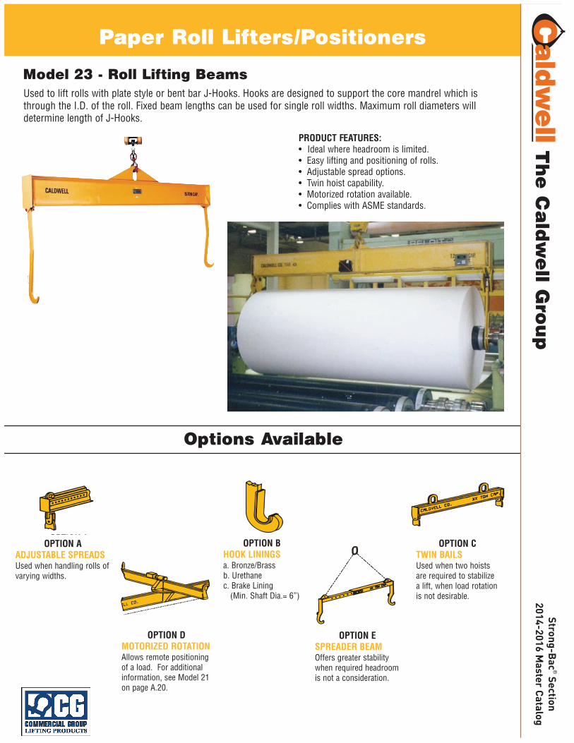
Model 23 - Roll Lifting Beams
OPTION E
SPREADER BEAM
Offers greater stabilitywhen required headroomis not a consideration.
OPTION A
ADJUSTABLE SPREADS
Used when handling rolls ofvarying widths.
OPTION B
HOOK LININGS
a. Bronze/Brassb. Urethanec. Brake Lining
(Min. Shaft Dia.= 6”)
OPTION C
TWIN BAILS
Used when two hoistsare required to stabilizea lift, when load rotationis not desirable.
OPTION D
MOTORIZED ROTATION
Allows remote positioning of a load. For additionalinformation, see Model 21 on page A.20.
Options Available
PRODUCT FEATURES:
• Ideal where headroom is limited.• Easy lifting and positioning of rolls.• Adjustable spread options.• Twin hoist capability.• Motorized rotation available.• Complies with ASME standards.
Used to lift rolls with plate style or bent bar J-Hooks. Hooks are designed to support the core mandrel which isthrough the I.D. of the roll. Fixed beam lengths can be used for single roll widths. Maximum roll diameters willdetermine length of J-Hooks.
Stro
ng
-Ba
c®
Se
ctio
n
20
14
-20
16
Ma
ste
r Ca
talo
gT
he
Ca
ldw
ell G
rou
p•
80
0-6
28
-4
26
3 •
ww
w.c
ald
we
llinc
.co
m

Coil Lifters & Upenders
A.40
Model 82RC - Close Stacking C-Hook
NOTE: E = Maximum coil width ÷ 2
Counterweight extends beyond arm one-half of the counterweight width, in capacities 25 ton and greater.
GUIDE
HANDLES
W
D
L
E
T A
C
B
HR
THROAT
PRODUCT FEATURES:• Recessed counterweight allows for close stacking of coils which
maximizes floor space.
• Handles a wide range of coil widths.
• Designed for heavy duty application.
• High tensile alloy steel plate reduces physical size and weight.• Counter balanced to hang level when empty.• Inside radius on hooks avoid coil edge contact.• Curved coil saddle is standard.
• Guide handle for ease of hook positioning.• Available with optional padding for additional coil protection.• Complies with ASME standards.
Dimensions (inches)
Lifting Arm Bail Dimensions
Model Capacity Coil Width Length Depth Width HR Opening Thk. Weight
Number (tons) Max. Min. Throat L D W Headroom A B C T (lbs.)
82RC-5-36 36 24 24 30 5-5/16 4 37-1/4 1-1/2 4 7 1-1/4 550
82RC-5-48 5 48 30 24 39 6-1/8 4 38-1/16 1-1/2 4 7 1-1/4 707
82RC-5-60 60 36 24 48 6-15/16 4 39 1-1/2 4 7 1-1/4 853
82RC-7 1/2-36 36 24 24 30 5-5/8 4 37-1/2 1-1/2 4 7 1-1/2 750
82RC-7 1/2-48 7-1/2 48 30 24 39 6-3/8 4 38-1/4 1-1/2 4 7 1-1/2 996
82RC-7 1/2-60 60 36 24 48 6-15/16 4 39 1-1/2 4 7 1-1/2 1161
82RC-10-48 48 30 24 39 7-3/16 4 41-1/4 2 5 9 1-3/4 1200
82RC-10-60 10 60 36 24 48 7-5/8 4 41-1/2 2 5 9 1-3/4 1645
82RC-10-72 72 42 24 57 7-1/4 4 41-1/8 2 5 9 1-3/4 2100
82RC-15-48 48 30 30 39 7-1/4 4 47-7/8 2 5 9 1-3/4 2054
82RC-15-60 15 60 36 30 48 8 4 48 2-1/4 5 9 1-3/4 2410
82RC-15-72 72 42 30 57 8-3/4 4 48-3/4 2 5 9 1-3/4 2814
82RC-20-60 60 36 30 48 9-1/8 4 52-1/8 2-1/4 6 12 2 2864
82RC-20-7220
72 42 30 57 9-3/4 4 52-1/2 2-1/4 6 12 2 2951
82RC-25-60 60 36 34 48 9 4 57-3/4 2-1/2 6 14 2-1/4 3077
82RC-25-7225
72 42 34 57 9-3/4 4 58-3/4 2-1/2 6 14 2-1/4 3570
82RC-30-60 60 36 34 48 9-7/8 4 58-3/4 2-3/4 6 14 2-1/2 3480
82RC-30-7230
72 42 34 57 10-5/8 4 59-3/8 2-3/4 6 14 2-1/2 4260
82RC-40-72 40 72 42 38 57 11 5 68 3-1/4 7 18 3 6100
COIL WIDTH
Other sizes available, consult factory.
SPECIFICATIONS
Center of the hoist and bail must
be in-line with the load's center
of gravity.
Stro
ng
-Ba
c®
Se
ctio
n
20
14
-20
16
Ma
ste
r Ca
talo
gT
he
Ca
ldw
ell G
rou
p•
80
0-6
28
-4
26
3 •
ww
w.c
ald
we
llinc
.co
m

Coil Lifters and Upenders
A.44
Model 83HW - Vertical “Eye” Coil Grab
DCOIL I.D.
F
Dimensions (inches)
Coil
Model Capacity Coil I.D. Width HR Weight
Number (tons) Min. Max. W Headroom A B C T F D J (lbs.)
83HW-2-1/2-24 2-1/2 16 24 20 36 1-1/2 3 5 3/4 5 3/4 15-1/2 250
83HW-5-24 5 16 24 24 41 2 4 7 1 6 1 15-1/2 350
83HW-7-1/2-24 7-1/2 16 24 24 42 2 4 7 1 6 1 15-1/2 425
83HW-10-24 10 16 24 30 50 2-1/2 5 9 1-1/4 6 1-1/2 15-1/2 500
Other sizes available, consult factory.
PRODUCT FEATURES:• Handles any size coil I.D. from 16" to 24".
• Efficient handling of vertically stacked coils.
• Available with chain wheel drive.
• Complies with ASME standards.
SPECIFICATIONS
Stro
ng
-Ba
c®
Se
ctio
n
20
14
-20
16
Ma
ste
r Ca
talo
gT
he
Ca
ldw
ell G
rou
p•
80
0-6
28
-4
26
3 •
ww
w.c
ald
we
llinc
.co
m

Sheet Lifters
A.55
Model 60M - Motorized Heavy Duty Sheet Lifters
PRODUCT FEATURES:• Versatile handling of bundles, sheets, plates and other
materials stacked horizontally.• Low headroom design for optimum lifting capabilities.• One person operation minimizes handling cost.• Self-locking worm gear drive for leg adjustment is standard.• Easy adjustment for different sheet widths.• Motorized leg adjustment, 460 volt. • Rack and pinion leg drive.• Designed for ease of maintenance.• Broad adjustment range handles various load widths.• Complies with ASME standards.
PRODUCT OPTIONS:• Battery powered motorization. • End chains with plate hooks (recommended for all widths 72”
and greater). • Extended grab shoe lengths.• Longer legs increase load clearance.• Controls shipped mounted or loose.• Other voltages available.
Dimensions (inches)
Model Capacity Load Width HR Shoe Min. Bail Opening Weight
Number (tons) Min. Max. Headroom D Aisle A B C T (lbs.)
60M-20-96 20 38 96 45 5.25 15 2.5 5 9 1.5 3150
Other sizes available, consult factory.
SPECIFICATIONS
Bail Opening
Do not lift loosely bundled, thin or oily sheets.
120
HR
24
D
LOAD WIDTH
B
A
C
T
Special 10 ton unit withextended bundle height.
Stro
ng
-Ba
c®
Se
ctio
n
20
14
-20
16
Ma
ste
r Ca
talo
gT
he
Ca
ldw
ell G
rou
p•
80
0-6
28
-4
26
3 •
ww
w.c
ald
we
llinc
.co
m

Pallet Lifters
A.64
Model 90 - Standard Fixed Forks Pallet Lifter
Model 95 - Heavy Duty Fixed Forks Pallet Lifter
PRODUCT FEATURES:• Double frame design for heavy capacities.
• Counter balanced to hang level when empty.
• Maintenance free.
• Complies with ASME standards.
E
B x C
NL
W
M
A
HR
J
PRODUCT FEATURES:• Converts overhead crane to lift truck.
• Counter balanced to hang level when empty.
• Maintenance free.
• Allows for ease of loading/unloading in not easily accessible areas.
• Complies with ASME standards.
Dimensions (inches)
Model Capacity Forks Bail Weight
Number (tons) L M N W E A B C J* HR (lbs.)
95-7 1/2-48 7-1/2 48 6 2-1/2 30 24 2 5 9 48 65 1910
95-7 1/2-60 7-1/2 60 10 3 38 30 2 5 9 60 79 2400
95-10-48 10 48 10 3 30 24 2 5 9 48 69 1950
95-10-60 10 60 10 3 38 30 2 5 9 60 81 3100
95-15-48 15 48 10 3 38 24 2 6 12 60 84 2250
95-15-60 15 60 10 3 38 30 2 6 12 60 75 3800
95-20-60 20 60 7 4 38 30 2-1/4 6 12 60 88 4300
95-20-72 20 72 8-1/4 4 44 36 2-1/4 6 12 60 88 4850
Dimensions (inches)
Model Capacity Forks Bail Weight
Number (tons) L M N W E A B C J* HR (lbs.)
90-1-36 1 36 2 2 25 18 1 6 5 48 57-1/2 292
90-1-42 1 42 2 2 25 21 1 6 5 48 57-1/2 310
90-1-48 1 48 2 2 25 24 1 6 5 48 58-1/2 371
90-1 1/2-36 1-1/2 36 3 2 25 18 1 6 5 48 58-1/2 388
90-1 1/2-42 1-1/2 42 3 2 25 21 1 6 5 48 58-1/2 432
90-1 1/2-48 1-1/2 48 3 2 25 24 1 6 5 48 58-1/2 459
90-2-36 2 36 3 2 25 18 1 6 5 48 59-1/2 448
90-2-42 2 42 4 2 25 21 1 6 5 48 59-1/2 536
90-2-48 2 48 4 2 25 24 1 6 5 48 59-1/2 627
90-3-42 3 42 4-1/2 2-1/2 25 21 1-1/2 6-1/8 7 48 61-1/2 766
90-3-48 3 48 4-1/2 2-1/2 27 24 1-1/2 6-1/8 7 48 61-1/2 823
90-3-54 3 54 4-1/2 2-1/2 30 27 1-1/2 6-1/8 7 48 61-1/2 969
90-4-48 4 48 5 3 27 24 1-1/2 6-1/8 7 48 63-1/2 1176
90-4-60 4 60 5 3 30 30 1-1/2 6-1/8 7 60 75-1/2 1393
90-5-48 5 48 5 3 30 24 1-1/2 6-1/8 7 48 63-1/2 1193
90-5-60 5 60 4-1/2 2-1/2 38 30 1-1/2 8-1/8 7 60 75-1/2 1403
L
N
W
M
HR
A
B x C
JE
Center of hoist and bail must be in-line
with the load's center of gravity.
SPECIFICATIONS
SPECIFICATIONS
* Additional 3" - 4" clearance recommended above load for ease of loading and unloading the lifter.
* Additional 3" - 4" clearance recommended above load for ease of loading and unloading the lifter.
Stro
ng
-Ba
c®
Se
ctio
n
20
14
-20
16
Ma
ste
r Ca
talo
gT
he
Ca
ldw
ell G
rou
p•
80
0-6
28
-4
26
3 •
ww
w.c
ald
we
llinc
.co
m

A.77
Lifting Tongs
Model 77 - Bale Lifting Tongs
Standard Indentation Type
PRODUCT FEATURES:• Lifts bales of paper, cotton, and other materials.
• Wide gripping surface for load stability.
• Includes Auto-Latch mechanism for one person operation.
• Complies with ASME standards.
Model Rated Capacity Bale Width Unit Height Pad Dimensions (in.) Weight
Number (tons) (in.) Loaded (in.) Width Height (lbs.)
77-1/2-36 1/2 36 52 18 9 280
77-1/2-48 1/2 48 56 18 9 300
77-1-36 1 36 52 18 9 280
77-1-48 1 48 56 18 9 300
SPECIFICATIONS
Stro
ng
-Ba
c®
Se
ctio
n
20
14
-20
16
Ma
ste
r Ca
talo
gT
he
Ca
ldw
ell G
rou
p•
80
0-6
28
-4
26
3 •
ww
w.c
ald
we
llinc
.co
m
Rotating Crane Hooks
A.68
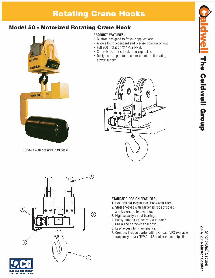
Model 50 - Motorized Rotating Crane Hook
PRODUCT FEATURES:
• Custom designed to fit your applications.• Allows for independent and precise position of load.• Full 360° rotation @ 1-1/2 RPM.• Controls feature soft-starting capability.• Designed to operate on either direct or alternating
power supply.
1
2
3
4
5
Shown with optional load scale.
STANDARD DESIGN FEATURES:
1. Heat treated forged steel hook with latch.2. Steel sheaves with hardened rope grooves
and tapered roller bearings. 3. High capacity thrust bearing. 4. Heavy duty helical-worm gear motor. 5. Chain and sprocket final drive. 6. Easy access for maintenance.7. Controls include starter with overload, VFD (variable
frequency drive) NEMA - 12 enclosure and pigtail.
Stro
ng
-Ba
c®
Se
ctio
n
20
14
-20
16
Ma
ste
r Ca
talo
gT
he
Ca
ldw
ell G
rou
p•
80
0-6
28
-4
26
3 •
ww
w.c
ald
we
llinc
.co
m

Material Handling
A.72
PRODUCT FEATURES:
• Organize material for a specific job.
• Quickly transport tools or components
from one area to another.
• Easily keep inventory contained and under control.
• Designed to fit your specific application requirements.
• Complies with ASME standards.
Caldwell custom designed material baskets provide the ideal solution when lifting and
transporting components on the job site or manufacturing facility.
Caldwell material baskets are not rated for handling personnel.
Model MB - Material Baskets
Heavy duty steel with solid
steel door and fork pockets. Lightweight aluminum with
mesh door and fork pockets.
Short, solid sided
basket with no door.
Stro
ng
-Ba
c®
Se
ctio
n
20
14
-20
16
Ma
ste
r Ca
talo
gT
he
Ca
ldw
ell G
rou
p•
80
0-6
28
-4
26
3 •
ww
w.c
ald
we
llinc
.co
m
C.6
Standard Posi-Turner®
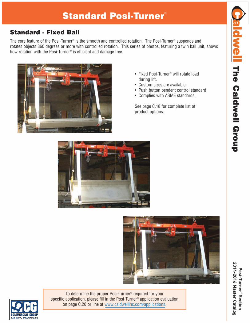
Standard - Fixed Bail
The core feature of the Posi-Turner® is the smooth and controlled rotation. The Posi-Turner® suspends and
rotates objects 360 degrees or more with controlled rotation. This series of photos, featuring a twin bail unit, shows
how rotation with the Posi-Turner® is efficient and damage free.
• Fixed Posi-Turner® will rotate load
during lift.
• Custom sizes are available.
• Push button pendent control standard
• Complies with ASME standards.
See page C.18 for complete list of
product options.
To determine the proper Posi-Turner® required for your specific application, please fill in the Posi-Turner® application evaluation
on page C.20 or line at www.caldwellinc.com/applications.
Po
si-T
urn
er®
Se
ctio
n
20
14
-20
16
Ma
ste
r Ca
talo
gT
he
Ca
ldw
ell G
rou
p•
80
0-6
28
-4
26
3 •
ww
w.c
ald
we
llinc
.co
m

C.7
Standard - Fixed Bail
Standard Posi-Turner®
Model Rated Maximum Roller HR Headroom Unit
Number Capacity (lbs.) Sling Span (in.) Single / Double Dia. (in.) (in.) Weight (lbs.)
.5FS-72 500 72 S 2.0 14.5 245
1FS-48 1000 48 S 2.0 14.5 225
1.5FS-72 72 S 4.0 28 365
1.5FS-84 84 S 4.0 28 400
1.5FS-96 1500 96 S 4.0 28 430
1.5FS-108 108 S 4.0 28 455
1.5FS-120 120 S 4.0 28 480
2FS-80 80 S 5.6 32.5 750
2FS-120 2000 120 S 5.6 32.5 1050
2FS-250 250 D 5.6 35 2250
3FS-80 80 S 5.6 32.5 750
3FS-120 3000 120 S 5.6 32.5 1200
3FS-250 250 D 5.6 35 2550
4FS-80 80 S 6.6 36.4 900
4FS-120 4000 120 S 6.6 36.4 1300
4FS-250 250 D 6.6 39 2900
6FS-80 80 S 8.6 36.4 1000
6FS-120 6000 120 S 8.6 36.3 1500
6FS-250 250 D 8.6 39 3200
10FS-80 80 S 8.6 38.8 2200
10FS-120 10000 120 S 8.6 38.8 2300
10FS-250 250 D 8.6 41 4200
16FS-80 80 S 10.8 45 3000
16FS-120 16000 120 S 10.8 45 3600
16FS-250 250 D 6.6 47 4600
22FS-15022000
150 D 6.6 45 3300
22FS-270 270 D 6.6 51 4900
33FS-15033000
150 D 8.6 53 3900
33FS-270 270 D 8.6 54 7900
44FS-15044000
150 D 10.8 60 5700
44FS-270 270 D 10.8 61 9700
55FS-15055000
150 D 10.8 63 5700
55FS-270 270 D 10.8 70 13200
66FS-15066000
150 D 10.8 69 8000
66FS-270 270 D 10.8 75 17800
88FS-15088000
150 D 10.8 75 10800
88FS-270 270 D 10.8 83 23700
110FS-150110000
150 D 12.8 75 12900
110FS-270 270 D 12.8 86 27900
Application evaluation required; consult factory for additional information.
DOUBLE ROLLER SLING SPAN
HR
SINGLE ROLLER SLING SPAN
HR
SPECIFICATIONS
Po
si-T
urn
er®
Se
ctio
n
20
14
-20
16
Ma
ste
r Ca
talo
gT
he
Ca
ldw
ell G
rou
p•
80
0-6
28
-4
26
3 •
ww
w.c
ald
we
llinc
.co
m

Rig-Release® Manual Releasing Hook
E.6
PRODUCT FEATURES:• Rope Guide allows rigging to be released when hook is either
above or beside the operator. If hook is located below the operator please see Upward Pull option on page E.20.
• Designed for rugged outdoor use.• Easy to use - simply rig, lift, set and release.• LOCK & CAPTURE feature engages with very little load weight (see Minimum Load in chart below).• Rated load capacity can be lifted from either Lift Arm or the lower Strip Sling Hook. Do not
exceed rated capacity of hook.• Oversized bail for easy mounting on crane hook - 5, 10 & 15 ton units provided with fixed bails. • Designed and manufactured to ASME standards.
Patent No. 7,380,849
SPECIFICATIONS - Manual Release
Model RR - Manual Release Unit
Model Rated Weight
Number Cap. (tons) D E F G J K L O A B C T (lbs.)
RR-1 1 1.15 0.75 1.25 2.77 4.25 23.10 19.75 0.89 0.63 3.00 6.00 0.63 14
RR-2.5 2.5 1.75 1.00 1.50 4.25 9.56 31.67 26.88 1.09 0.63 3.00 6.00 0.63 45
RR-5 5 1.83 1.50 1.50 5.00 11.13 36.40 30.75 1.36 2.00 4.00 7.00 1.25 110
RR-10 10 2.25 1.75 2.00 6.31 11.00 41.16 32.13 2.08 2.00 4.00 7.00 1.25 200
RR-15 15 3.00 2.50 2.50 6.31 15.00 49.25 39.25 2.27 2.50 5.00 9.00 1.50 325
SPECIFICATIONSRated *Minimum Recommended **Maximum Allowable
Model Capacity Load (lbs.) Lifting Slings Rigging Weight (lbs.)
Number (tons) Basket Choker Rope Dia. (inches) Basket Choker
RR-1 1 30 15 3/8 14 7
RR-2.5 2.5 80 40 5/8 28 14
RR-5 5 230 115 7/8 60 30
RR-10 10 230 115 1-1/4 100 50
RR-15 15 400 200 1-1/2 100 50
Chart data is based uponthe minimum number of springs.
*If minimum load weight is not met, safety mechanism will not engage into the LOCK & CAPTURE position. **If maximum allowable rigging weight is exceeded, unit will remain in the LOCK & CAPTURE position and can not be released.
If the maximum allowable rigging weight needs to be increased, additional springs can be added, refer to the Instruction Manual.
Rigging
Lifting at less than minimumload can result in injury or death.
NOTE: For larger capacities see page E.21.
Dimensions (inches) Bail Dimensions (inches)
1 Ton Unit Shown
Rig
-Re
lea
se®
Se
ctio
n
20
14
-20
16
Ma
ste
r Ca
talo
gT
he
Ca
ldw
ell G
rou
p•
80
0-6
28
-4
26
3 •
ww
w.c
ald
we
llinc
.co
m
E.7
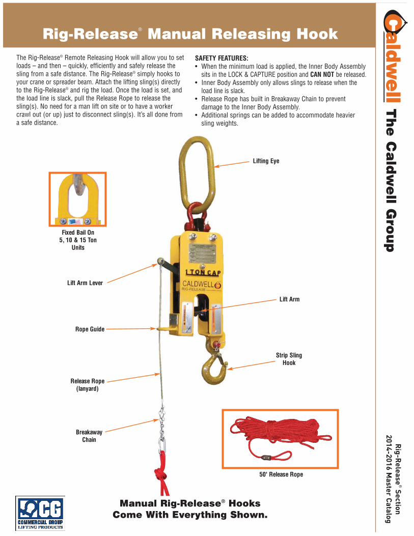
Rig-Release® Manual Releasing Hook
SAFETY FEATURES:• When the minimum load is applied, the Inner Body Assembly
sits in the LOCK & CAPTURE position and CAN NOT be released.• Inner Body Assembly only allows slings to release when the
load line is slack.• Release Rope has built in Breakaway Chain to prevent
damage to the Inner Body Assembly.• Additional springs can be added to accommodate heavier
sling weights.
The Rig-Release® Remote Releasing Hook will allow you to setloads – and then – quickly, efficiently and safely release thesling from a safe distance. The Rig-Release® simply hooks toyour crane or spreader beam. Attach the lifting sling(s) directlyto the Rig-Release® and rig the load. Once the load is set, andthe load line is slack, pull the Release Rope to release thesling(s). No need for a man lift on site or to have a workercrawl out (or up) just to disconnect sling(s). It’s all done froma safe distance.
Lifting Eye
Lift Arm
Strip SlingHook
Release Rope(lanyard)
Rope Guide
50' Release Rope
Fixed Bail On5, 10 & 15 Ton
Units
Lift Arm Lever
Manual Rig-Release® Hooks
Come With Everything Shown.
Breakaway Chain R
ig-R
ele
as
e®
Se
ctio
n
20
14
-20
16
Ma
ste
r Ca
talo
gT
he
Ca
ldw
ell G
rou
p•
80
0-6
28
-4
26
3 •
ww
w.c
ald
we
llinc
.co
m

Booms
G.4
The Fixed Boom, Model FB, has a telescoping boom with a maximum horizontal reach of 12 feet. This model is
available in 3,000, 4,000, 6,000 and 8,000 lb. capacities.
PRODUCT FEATURES:• Alternate hook positions. • Handle at end for easy extension.
• Telescoping boom. • Fixed or swivel hooks available.
• Restraining chain with grab hook. • Boom locking t-pin.
C
A
30
HR
36
7'
EXTENDS TO 12'(1' INCREMENTS)
B 12TYP.
Model FB - Telescopic Fork Lift Booms
Dimensions (in.) Maximum Capacity @ Hook Position (lbs.)Model Weight
Number A B C HR O 3’-6’ 7’ 8’ 9’ 10’ 11’ 12’ (lbs.)
FB-302-1/2 7-1/2 22
16 1.00 3000 3000 2600 2200 1900 1600 1500 340
FB-40 16 1.09 4000 3200 2600 2200 1900 1600 1500 340
FB-602-1/2 7-1/2 22
17 1.36 6000 5000 4200 3500 3000 2700 2500 390
FB-80 18 1.61 8000 7000 5700 4800 4100 3600 3100 520
SPECIFICATIONS
O
Model FBFixed Type Fork Lift Boom
NOTE: All dimensions on drawings shown in inches unless stated.
NOTE: Models FB-30 and FB-40 are only available with swivel hooks.
Capacity of lift truck and attachment combination may be less than
capacity shown on attachment. Consult lift truck manufacturer.
Lif-T
ruc™
Se
ctio
n
20
14
-20
16
Ma
ste
r Ca
talo
gT
he
Ca
ldw
ell G
rou
p•
80
0-6
28
-4
26
3 •
ww
w.c
ald
we
llinc
.co
m

G.17
Rated Dimensions (in.)Model Capacity Weight
Number (lbs.) A B C D E O (lbs.)
15-2-20 4000 20 6-5/8 2-1/2 10-3/8 1-7/16 1-11/32 60
15-5-24 10000 24 9-3/8 2-1/2 11-21/32 1-7/16 1-11/32 68
A
CF
DE
O
LIFT TRUCKFORK
B A
C
OD
E
Lift Truck Fork
B
Model 10S-2-20
Model 10 - Single Hook Beam - Fixed or Swivel
Model 15 - Double Hook Beam - Swivel
SPECIFICATIONS
Model Model Rated Dimensions (in.)
Number Number Capacity Fixed Swivel Weight
Fixed Swivel (lbs.) A C D F F E O (lbs.)
10-2-20 10S-2-20 4000 20 3-1/4 9-1/8 7-1/4 8-7/8 1-1/8 1-5/32 21
10-5-24 10S-5-24 10000 24 3-1/4 10-3/4 9-1/4 11-7/16 1-13/16 1-11/16 42
10-5-36 10S-5-36 10000 36 3-1/4 16-3/4 9-1/4 11-7/16 1-13/16 1-11/16 80
10-7.5-36 10S-7.5-36 15000 36 4-1/4 16-1/4 13-3/4 15-3/4 2-1/4 2-7/32 166
10-10-36 10S-10-36 20000 36 4-1/4 16 14-5/8 16-7/16 2-19/32 2-13/32 180
10-15-36 10S-15-36 30000 36 4-1/4 15-7/8 14-1/2 16-5/16 2-19/32 2-13/32 210
SPECIFICATIONS
Model 10S-7.5-36
Fork BeamsL
if-Tru
c™
Se
ctio
n
20
14
-20
16
Ma
ste
r Ca
talo
gT
he
Ca
ldw
ell G
rou
p•
80
0-6
28
-4
26
3 •
ww
w.c
ald
we
llinc
.co
m