Embed Size (px)
Citation preview

Wire Rope & Slings
79
Wire
Ro
pe
Wire Rope & Slings
Wir
eR
ope
80
D/d - Basket Hitch Effect
Tests have shown that when a sling body is bent around a diameter, the strength of the sling is decreased.
D/d ratio is the ratio of the diameteraround which the sling is bent, divided by the body diameter of the sling.
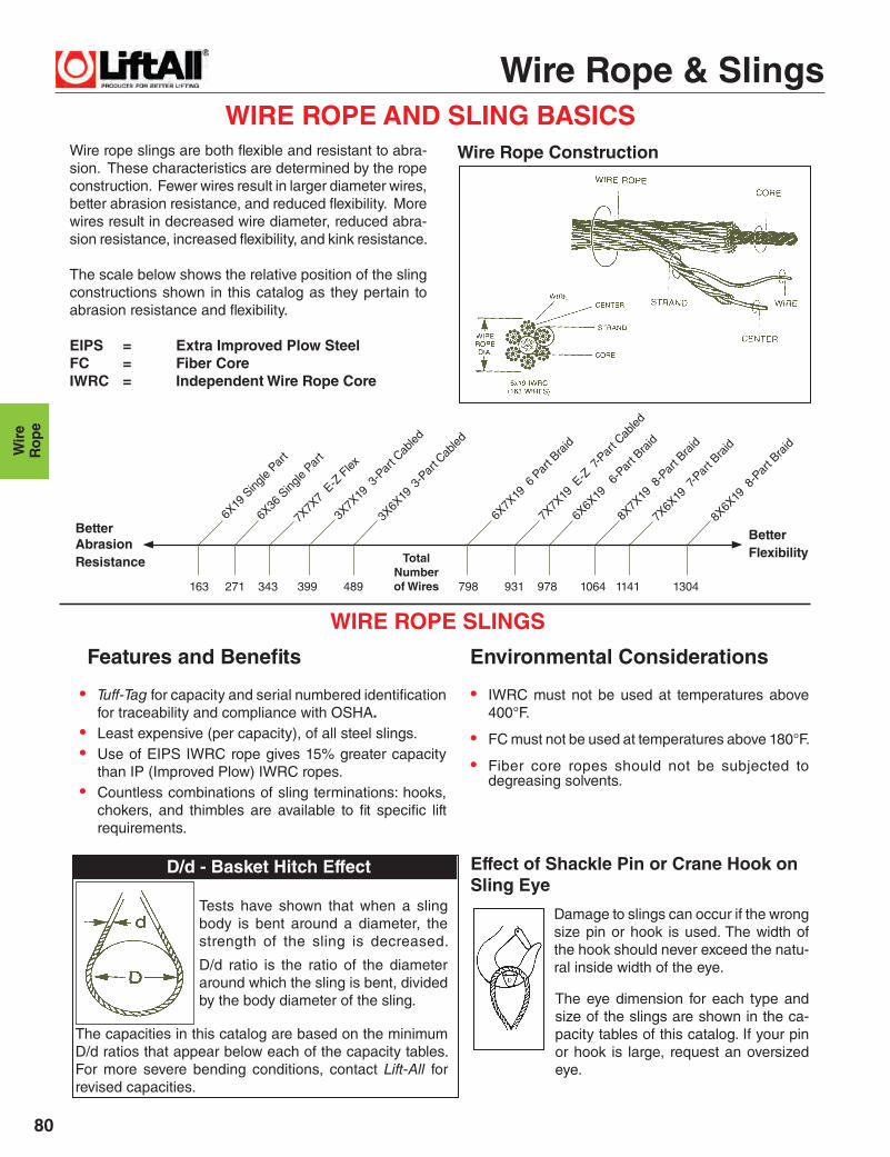
WIRE ROPE AND SLING BASICSWire rope slings are both fl exible and resistant to abra-sion. These characteristics are determined by the rope construction. Fewer wires result in larger diameter wires, better abrasion resistance, and reduced fl exibility. More wires result in decreased wire diameter, reduced abra-sion resistance, increased fl exibility, and kink resistance.
The scale below shows the relative position of the sling constructions shown in this catalog as they pertain to abrasion resistance and fl exibility.
EIPS = Extra Improved Plow SteelFC = Fiber CoreIWRC = Independent Wire Rope Core
Better Abrasion Resistance
Better Flexibility
WIRE ROPE SLINGS
• Tuff-Tag for capacity and serial numbered identifi cation for traceability and compliance with OSHA.
• Least expensive (per capacity), of all steel slings.• Use of EIPS IWRC rope gives 15% greater capacity
than IP (Improved Plow) IWRC ropes.• Countless combinations of sling terminations: hooks,
chokers, and thimbles are available to fi t specifi c lift requirements.
Wire Rope Construction
6X19
Sing
le Par
t
6X36
Sing
le Par
t
7X7X
7 E
-Z F
lex
3X6X
19 3
-Par
t Cab
led
3X7X
19 3
-Par
t Cab
led
6X7X
19 6
Par
t Bra
id
7X7X
19 E
-Z 7
-Par
t Cab
led
6X6X
19
6-Par
t Bra
id
8X7X
19 8
-Par
t Bra
id
7X6X
19 7
-Par
t Bra
id
8X6X
19 8
-Par
t Bra
id
TotalNumberof Wires163 271 343 399 489 798 931 978 1064 1141 1304
The capacities in this catalog are based on the minimum D/d ratios that appear below each of the capacity tables. For more severe bending conditions, contact Lift-All for revised capacities.
• IWRC must not be used at temperatures above 400°F.
• FC must not be used at temperatures above 180°F.
• Fiber core ropes should not be subjected to degreasing solvents.
Effect of Shackle Pin or Crane Hook on Sling Eye
Features and Benefi ts Environmental Considerations
The eye dimension for each type and size of the slings are shown in the ca-pacity tables of this catalog. If your pin or hook is large, request an oversized eye.
Damage to slings can occur if the wrong size pin or hook is used. The width of the hook should never exceed the natu-ral inside width of the eye.
Wire Rope & Slings
81
Wire
Ro
pe
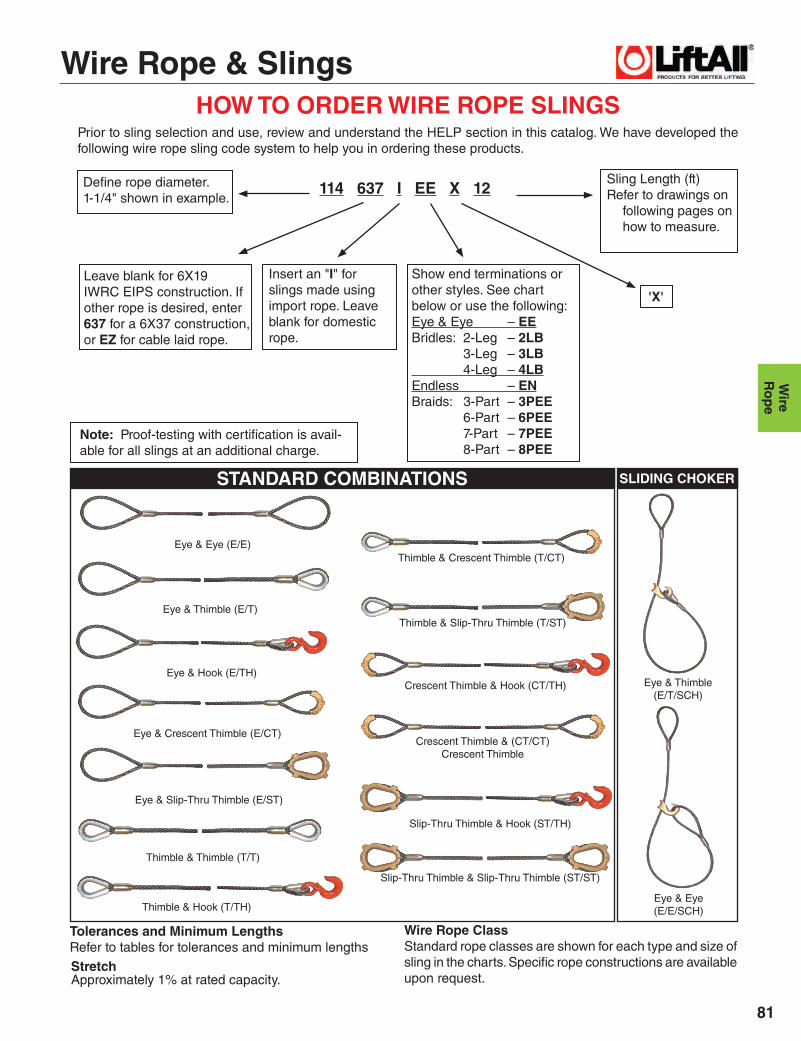
HOW TO ORDER WIRE ROPE SLINGSPrior to sling selection and use, review and understand the HELP section in this catalog. We have developed the following wire rope sling code system to help you in ordering these products.
Defi ne rope diameter.1-1/4" shown in example.
Tolerances and Minimum LengthsRefer to tables for tolerances and minimum lengths
Note: Proof-testing with certifi cation is avail-able for all slings at an additional charge.
Eye & Eye (E/E)
Eye & Thimble (E/T)
Eye & Hook (E/TH)
Eye & Crescent Thimble (E/CT)
Eye & Slip-Thru Thimble (E/ST)
Thimble & Crescent Thimble (T/CT)
Thimble & Slip-Thru Thimble (T/ST)
Crescent Thimble & Hook (CT/TH)
Crescent Thimble & (CT/CT)Crescent Thimble
Slip-Thru Thimble & Hook (ST/TH)
Eye & Thimble (E/T/SCH)
Eye & Eye (E/E/SCH)
Thimble & Thimble (T/T)
Thimble & Hook (T/TH)
Leave blank for 6X19 IWRC EIPS construction. Ifother rope is desired, enter 637 for a 6X37 construction,or EZ for cable laid rope.
Show end terminations orother styles. See chart below or use the following:Eye & Eye – EEBridles: 2-Leg – 2LB 3-Leg – 3LB 4-Leg – 4LBEndless – ENBraids: 3-Part – 3PEE 6-Part – 6PEE 7-Part – 7PEE 8-Part – 8PEE
114 637 I EE X 12
Slip-Thru Thimble & Slip-Thru Thimble (ST/ST)
StretchApproximately 1% at rated capacity.
Wire Rope ClassStandard rope classes are shown for each type and size of sling in the charts. Specifi c rope constructions are available upon request.
'X'
Sling Length (ft)Refer to drawings on
following pages on how to measure.
STANDARD COMBINATIONS SLIDING CHOKER
Insert an "I" for slings made using import rope. Leave blank for domestic rope.

Wire Rope & Slings
Wir
eR
ope
82
PERMALOC WIRE ROPE SLINGSLift-All Permaloc slings are made using the fl emish splice technique to form the eyes. Unlike the simple return loop method that places 100% of its strength on the swaged sleeve, Permaloc slings have reserve strength should the sleeve become damaged in use.
Features and Benefi tsMaintains all the basic Lift-All wire rope sling features plus ...
Promotes Safety
• Reserve strength: Integrity of eyes not solelydependent upon steel sleeves.
• IWRC resists crushing better than FC ropes.
Saves Money
• When specifi ed, thimble eyes protect wire ropefrom wear for increased life.
• Good abrasion resistance for longer life.
Permaloc With Single Part Body
Note: Larger diameter slings available. Basket ratings are based on a minimum D/d of 25.1 Minimum sling length when using standard eyes.
Length Tolerances (Single Part Wire Rope Slings): Standard length tolerance is plus or minus two rope diameters, OR plus or minus 0.5% of the sling length, whichever is greater.** See Sliding Choker Hook capacities in HARDWARE section when using these hooks.
WARNING *
IWRC (Independent Wire Rope Core) Fiber core available at reduced capacities
Do not exceed rated capacities. Sling capacity decreases as the angle from horizontal decreases. Slings should not be used at angles of less than 30°.Refer to the Effect of Angle chart in the HELP section of this catalog.
Wire Rope Class
Rope Dia. (in.)
EIPS IWRC
1Min.Sling
Length
StandardEye Size
W X L(in.)
ThimbledEye Size
W X L(in.)
EyeHookCap.
(tons)
CrescentThimbleEye Size
W X L (in.)
Slip ThruThimbleEye Size
W X L (in.)
Sliding ChokerHook
**(in.)
Rated Capacity* (tons)
Vertical ChokerVertical Basket
1/4 .65 .48 1.3 1'-6" 2 X 4 0.88 X 1.63 1 2 X 4 2.13 X 4.13 3/8
5/16 1.0 .74 2.0 1'-9" 2.5 X 5 1.06 X 1.88 1 2 X 4 2.50 X 4.13 3/8
3/8 1.4 1.1 2.9 2'-0" 3 X 6 1.13 X 2.13 1.5 2 X 4 2.50 X 4.13 3/8
7/16 1.9 1.4 3.9 2'-3" 3.5 X 7 1.25 X 2.25 2 2 X 5 2.38 X 4.38 1/2
1/2 2.5 1.9 5.1 2'-6" 4 X 8 1.5 X 2.75 3 2.25 X 6 2.38 X 4.38 1/2**
9/16 3.2 2.4 6.4 2'-9" 4.5 X 9 1.5 X 2.75 4.5 2.25 X 7 2.38 X 4.38 5/8
5/8 3.9 2.9 7.8 3'-0" 5 X 10 1.75 X 3.25 4.5 2.75 X 7 3.38 X 6.63 5/8**
3/4 5.6 4.1 11 3'-6" 6 X 12 2 X 3.75 7 3.25 X 8.5 3.38 X 6.63 3/4**
7/8 7.6 5.6 15 4'-0" 7 X 14 2.25 X 4.25 11 4.5 X 10 3.75 X 7.13 7/8
1 9.8 7.2 20 4'-6" 8 X 16 2 X 4.5 11 4.5 X 11.5 3.75 X 7.13 1
1-1/8 12 9.1 24 5'-0" 9 X 18 2.88 X 5.13 15 4.88 X 13 4.38 X 8.38 1-1/8
1-1/4 15 11 30 5'-6" 10 X 20 3.5 X 6.5 15 5.5 X 14.5 4.38 X 8.38 1-1/4
1-3/8 18 13 36 6'-0" 11 X 22 3.5 X 6.25 22 6 X 16 5 X 9.5 1-3/8
1-1/2 21 16 42 7'-0" 12 X 24 3.5 X 6.25 22 6 X 17.5 5 X 9.5 1-1/2**
1-3/4 28 21 57 8'-0" 14 X 28 4.5 X 9 30 7 X 20 6.75 X 11.75 –
2 37 28 73 9'-0" 16 X 32 6 X 12 37 7.X 23.5 8 X 14.5 −
2-1/4 44 35 89 10'-0" 18 X 36 7 X 14 45 8.5 X 26 8 X 15.5 −
2-1/2 54 42 109 11'-0" 20 X 40 − − 8.5 X 29.5 − −
Mechanically swaged, fl emish eye splice
6X37
EIP
S IW
RC
Flemish splice technique
6X19
EIP
S IW
RC

Wire Rope & Slings
83
Wire
Ro
pe
PERMALOC BRIDLE SLINGSFeatures and Benefi tsMaintains all the basic Lift-All wire rope sling features plus ...
Promotes Safety
• Bridles provide better load control and balance.
• Independent wire rope core resists crushing.
Saves Money
• Alloy steel hardware assures long life.
• Thimble eyes protect wire rope from wear for increased life.
• Reduces load damage by using fi xed points on load.
Saves Time
• Easier rigging provided when hooking into fi xed lifting points.
Length Tolerances (Single Part Wire Rope Slings): Standard length tolerance is plus or minus two rope diameters, OR plus or minus 0.5% of the sling length, whichever is greater. The legs of bridle slings, or matched slings are normally held to within one rope diameter.
Other fi ttings and latches are available upon request.1 Minimum length based on thimbled eye and eye. WARNING *
2-Leg Bridle 3-Leg Bridle 4-Leg BridlePermalocBridle Slings(With Single Part Body)
Do not exceed rated capacities. Sling capacity decreases as the angle from horizontal decreases. Slings should not be used at angles of less than 30°. Refer to the Effect of Angle chart in the HELP section of this catalog.
RopeDia.(in.)
1Min.Sling
Length
EyeHookCap.
(tons)
Rated Capacity* (tons)
OblongLink
StockDia. (in.)
Rated Capacity* (tons)
OblongLink
StockDia. (in.)
Rated Capacity* (tons)
OblongLink
StockDia. (in.)60° 45° 30° 60° 45° 30° 60° 45° 30°
1/4 1'-3" 1 1.1 .91 .65 1/2 1.7 1.4 .97 1/2 2.2 1.8 1.3 1/2
5/16 1'-6" 1 1.7 1.4 1.0 1/2 2.6 2.1 1.5 1/2 3.5 2.8 2.0 3/4
3/8 1'-8" 1-1/2 2.5 2.0 1.4 1/2 3.7 3.0 2.2 3/4 5.0 4.1 2.9 3/4
7/16 1'-10" 2 3.4 2.7 1.9 3/4 5.0 4.1 2.9 3/4 6.7 5.5 3.9 1
1/2 2'-0" 3 4.4 3.6 2.5 3/4 6.6 5.4 3.8 1 8.8 7.1 5.1 1
9/16 2'-2" 4-1/2 5.5 4.5 3.2 3/4 8.3 6.8 4.8 1 11 9.0 6.4 1-1/4
5/8 2'-4" 4-1/2 6.8 5.5 3.9 1 10 8.3 5.9 1-1/4 14 11 7.8 1-1/2
3/4 2'-9" 7 9.7 7.9 5.6 1-1/4 15 12 8.4 1-1/2 19 16 11 1-3/4
7/8 3'-3" 11 13 11 7.6 1-1/4 20 16 11 1-1/2 26 21 15 2
1 3'-6" 11 17 14 9.8 1-1/2 26 21 15 1-3/4 34 28 20 2-1/4
1-1/8 4'-0" 15 21 17 12 1-1/2 31 26 18 1-3/4 42 34 24 2-3/4
1-1/4 4'-6" 15 26 21 15 1-3/4 38 31 22 2 51 42 30 2-3/4
1-3/8 5'-0" 22 31 25 18 1-3/4 46 38 27 2-1/4 – – – –
1-1/2 5'-6" 22 37 30 21 2 55 45 32 2-1/4 – – – –
1-3/4 6'-6" 30 49 40 28 2-1/4 – - – – – – – –
2 8'-0" 37 63 52 37 2-3/4 – – – – – – – –6X37
EIP
S IW
RC
6X19
EIP
S IW
RC
6X19
6X37
Wire Rope & Slings
Wir
eR
ope
84
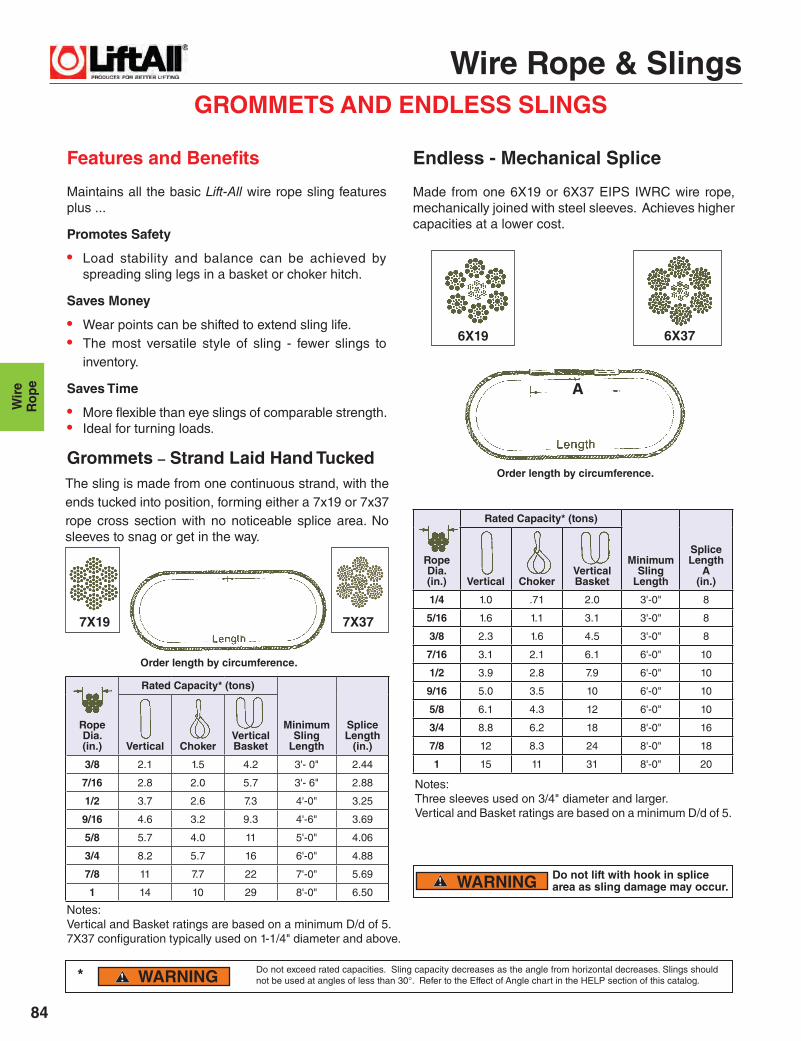
GROMMETS AND ENDLESS SLINGS
Features and Benefi ts
Maintains all the basic Lift-All wire rope sling features plus ...
Promotes Safety
• Load stability and balance can be achieved by spreading sling legs in a basket or choker hitch.
Saves Money
• Wear points can be shifted to extend sling life.• The most versatile style of sling - fewer slings to
inventory.
Saves Time
• More fl exible than eye slings of comparable strength.• Ideal for turning loads.
Made from one 6X19 or 6X37 EIPS IWRC wire rope, mechanically joined with steel sleeves. Achieves higher capacities at a lower cost.
Do not lift with hook in splice area as sling damage may occur.
Notes:Vertical and Basket ratings are based on a minimum D/d of 5. 7X37 confi guration typically used on 1-1/4" diameter and above.
WARNING
WARNING
6X19 6X37
7X19 7X37
Notes:Three sleeves used on 3/4" diameter and larger. Vertical and Basket ratings are based on a minimum D/d of 5.
Order length by circumference.
Order length by circumference.
Rope Dia. (in.)
Rated Capacity* (tons)
Minimum Sling
Length
Splice Length
(in.)Vertical ChokerVertical Basket
3/8 2.1 1.5 4.2 3'- 0" 2.44
7/16 2.8 2.0 5.7 3'- 6" 2.88
1/2 3.7 2.6 7.3 4'-0" 3.25
9/16 4.6 3.2 9.3 4'-6" 3.69
5/8 5.7 4.0 11 5'-0" 4.06
3/4 8.2 5.7 16 6'-0" 4.88
7/8 11 7.7 22 7'-0" 5.69
1 14 10 29 8'-0" 6.50
RopeDia.(in.)
Rated Capacity* (tons)
Minimum Sling
Length
Splice Length
A(in.)Vertical Choker
VerticalBasket
1/4 1.0 .71 2.0 3'-0" 8
5/16 1.6 1.1 3.1 3'-0" 8
3/8 2.3 1.6 4.5 3'-0" 8
7/16 3.1 2.1 6.1 6'-0" 10
1/2 3.9 2.8 7.9 6'-0" 10
9/16 5.0 3.5 10 6'-0" 10
5/8 6.1 4.3 12 6'-0" 10
3/4 8.8 6.2 18 8'-0" 16
7/8 12 8.3 24 8'-0" 18
1 15 11 31 8'-0" 20
The sling is made from one continuous strand, with the ends tucked into position, forming either a 7x19 or 7x37 rope cross section with no noticeable splice area. No sleeves to snag or get in the way.
*
Endless - Mechanical Splice
Grommets – Strand Laid Hand Tucked
Do not exceed rated capacities. Sling capacity decreases as the angle from horizontal decreases. Slings should not be used at angles of less than 30°. Refer to the Effect of Angle chart in the HELP section of this catalog.
A
Wire Rope & Slings
85
Wire
Ro
pe
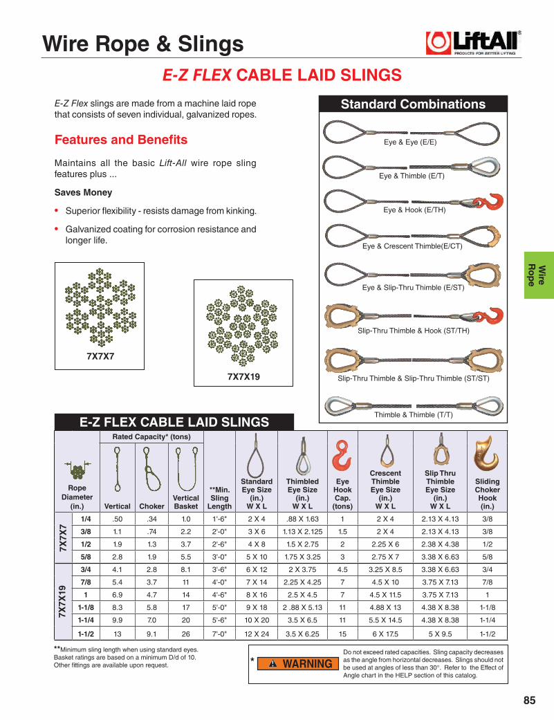
E-Z FLEX CABLE LAID SLINGS
E-Z Flex slings are made from a machine laid rope that consists of seven individual, galvanized ropes.
Features and Benefi ts
Maintains all the basic Lift-All wire rope sling features plus ...
Saves Money
• Superior fl exibility - resists damage from kinking.
• Galvanized coating for corrosion resistance and longer life.
**Minimum sling length when using standard eyes.Basket ratings are based on a minimum D/d of 10.Other fi ttings are available upon request.
Eye & Eye (E/E)
Eye & Thimble (E/T)
Eye & Hook (E/TH)
Eye & Crescent Thimble(E/CT)
Eye & Slip-Thru Thimble (E/ST)
Slip-Thru Thimble & Hook (ST/TH)
Slip-Thru Thimble & Slip-Thru Thimble (ST/ST)
Thimble & Thimble (T/T)
7X7X7
7X7X19
WARNING Do not exceed rated capacities. Sling capacity decreases as the angle from horizontal decreases. Slings should not be used at angles of less than 30°. Refer to the Effect of Angle chart in the HELP section of this catalog.
RopeDiameter
(in.)
Rated Capacity* (tons)
**Min.Sling
Length
StandardEye Size
(in.)W X L
ThimbledEye Size
(in.)W X L
EyeHookCap.
(tons)
CrescentThimbleEye Size
(in.)W X L
Slip Thru ThimbleEye Size
(in.)W X L
Sliding ChokerHook (in.)Vertical Choker
VerticalBasket
1/4 .50 .34 1.0 1'-6" 2 X 4 .88 X 1.63 1 2 X 4 2.13 X 4.13 3/8
3/8 1.1 .74 2.2 2'-0" 3 X 6 1.13 X 2.125 1.5 2 X 4 2.13 X 4.13 3/8
1/2 1.9 1.3 3.7 2'-6" 4 X 8 1.5 X 2.75 2 2.25 X 6 2.38 X 4.38 1/2
5/8 2.8 1.9 5.5 3'-0" 5 X 10 1.75 X 3.25 3 2.75 X 7 3.38 X 6.63 5/8
3/4 4.1 2.8 8.1 3'-6" 6 X 12 2 X 3.75 4.5 3.25 X 8.5 3.38 X 6.63 3/4
7/8 5.4 3.7 11 4'-0" 7 X 14 2.25 X 4.25 7 4.5 X 10 3.75 X 7.13 7/8
1 6.9 4.7 14 4'-6" 8 X 16 2.5 X 4.5 7 4.5 X 11.5 3.75 X 7.13 1
1-1/8 8.3 5.8 17 5'-0" 9 X 18 2 .88 X 5.13 11 4.88 X 13 4.38 X 8.38 1-1/8
1-1/4 9.9 7.0 20 5'-6" 10 X 20 3.5 X 6.5 11 5.5 X 14.5 4.38 X 8.38 1-1/4
1-1/2 13 9.1 26 7'-0" 12 X 24 3.5 X 6.25 15 6 X 17.5 5 X 9.5 1-1/2
7X7X
19
*
Standard Combinations
E-Z FLEX CABLE LAID SLINGS
7X7X
7

Wire Rope & Slings
Wir
eR
ope
86
E-Z FLEX TWO LEG BRIDLE SLINGS
Promotes Safety
• Bridles provide better load control and balance.
Saves Money
• Excellent fl exibility - resists damage from kinking.
• Galvanized coating for corrosion resistance and longer life.
• Alloy steel hardware assures long life.
Do not lift with hook in splice area as sling damage may occur.
** Minimum length based on thimbled eye and eye hook.
WARNING
WARNING
Eye Hook Choker
RopeDia. (in.)
Rated Capacity* (tons)
**Min.Sling
Length
OblongLink
StockDia.(in.)
EyeHookCap.
(tons)
SlidingChokerHook(in.)60° 45° 30° 60° 45° 30°
1/4 .87 .71 .50 .60 .49 .34 1'-3" 1/2 1 3/8
3/8 1.9 1.5 1.1 1.3 1.0 .74 1'-8" 1/2 1-1/2 3/8
1/2 3.2 2.6 1.9 2.2 1.8 1.3 2'-0" 3/4 2 1/2
5/8 4.8 3.9 2.8 3.3 2.7 1.9 2'-4" 1 3 5/8
3/4 7.0 5.8 4.1 4.8 3.9 2.8 2'-9" 1 4-1/2 3/4
7/8 9.4 7.6 5.4 6.4 5.2 3.7 3'-3" 1 7 7/8
1 12 9.7 6.9 8.2 6.7 4.7 3'-6" 1 1-/4 7 1
1-1/8 14 12 8.3 10 8.2 5.8 4'-0" 1-1/2 11 1-1/8
1-1/4 17 14 9.9 12 9.8 7.0 4'-6" 1-1/2 11 1-1/4
1-1/2 22 18 13 15 13 9.1 5'-6" 2 15 1-1/2
Saves Time
• Easier rigging when hooking into fi xed lifting points.
• Sliding choker hook speeds rigging of bundled materials.
Features and Benefi ts
Maintains all the basic Lift-All wire rope sling features plus ...
E-Z FLEX 2-Leg Bridles
*
7X7X
19
Do not exceed rated capacities. Sling capacity decreases as the angle from horizontal decreases. Slings should not be used at angles of less than 30°. Refer to the Effect of Angle chart in the HELP section of this catalog.
7X7X
7
Wire Rope & Slings
87
Wire
Ro
pe
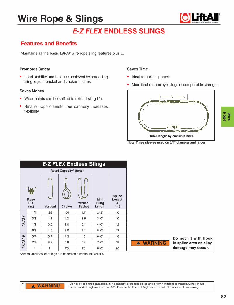
E-Z FLEX ENDLESS SLINGS
Promotes Safety
• Load stability and balance achieved by spreading sling legs in basket and choker hitches.
Saves Money
• Wear points can be shifted to extend sling life.
• Smaller rope diameter per capacity increases fl exibility.
Do not lift with hook in splice area as sling damage may occur.
E-Z FLEX Endless Slings
WARNING
WARNING
A
Vertical and Basket ratings are based on a minimum D/d of 5.
< >
Note: Three sleeves used on 3/4" diameter and larger
Order length by circumference
RopeDia. (in.)
Rated Capacity* (tons)
Min.Sling
Length
SpliceLength
A(in.)Vertical Choker
VerticalBasket
1/4 .83 .54 1.7 2'-3" 10
3/8 1.8 1.2 3.6 3'-0" 10
1/2 3.0 2.0 6.1 4'-0" 12
5/8 4.6 3.0 9.1 5'-0" 12
3/4 6.7 4.3 13 6'-0" 18
7/8 8.9 5.8 18 7'-0" 18
1 11 7.3 23 8'-0" 207X7X
19
*
Saves Time
• Ideal for turning loads.
• More fl exible than eye slings of comparable strength.
Features and Benefi ts
Maintains all the basic Lift-All wire rope sling features plus ...
Do not exceed rated capacities. Sling capacity decreases as the angle from horizontal decreases. Slings should not be used at angles of less than 30°. Refer to the Effect of Angle chart in the HELP section of this catalog.
7X7X
7

Wire Rope & Slings
Wir
eR
ope
88
HIDDEN TUCK HAND SPLICED SLINGS
Features and Benefi ts
Maintains all the basic Lift-All wire rope sling features plus ...
Promotes Safety
• Hidden Tuck buries wire ends to avoid snags and injuries.
Saves Time
• No steel sleeves to catch under load.
Basket ratings are based on a minimum D/d of 15.
Hidden Tuck Hand Spliced Fiber Core
RopeDia. (in.)
EIPS FC
Min.Sling
Length
StandardEyeSize
W x L(in.)
Rated Capacity* (tons)
Vertical ChokerVerticalBasket
1/4 .54 .42 1.1 2'-0" 3 X 6
5/16 .83 .66 1.7 2'-3" 3 X 6
3/8 1.2 .94 2.4 2'-6" 3 X 6
7/16 1.6 1.3 3.2 2'-9" 3.5 X 7
1/2 2.0 1.6 4.0 3'-0" 4 X 8
9/16 2.5 2.1 5.0 3'-6" 4.5 X 9
5/8 3.1 2.6 6.2 4'-0" 5 X 10
3/4 4.3 3.7 8.6 4'-6" 6 X 12
7/8 5.7 5.0 11 5'-6" 7 X 14
1 7.4 6.4 15 6'-0" 8 X 16
WARNING * Do not exceed rated capacities. Sling capacity decreases as the angle from horizontal decreases. Slings should not be used at angles of less than 30°. Refer to the Effect of Angle chart in the HELP section of this catalog.
6X19
EIP
S F
C

Wire Rope & Slings
89
Wire
Ro
pe
MULTI-PART CABLED SLINGS3-PART CABLED
Constructed by hand cabling one rope to form a 3-part body with 2-part eyes.
Features and Benefi ts
Maintains all the basic Lift-All wire rope sling features plus …
Saves Money
• Good abrasion resistance increases useful life of sling.
• Resists damage from kinking.
Saves Time
• Flexible and easy to handle.
• Small sleeve over component rope won't get in the way.
3-PART CABLED
Constructed by hand cabling one rope to form a 7-part body with 4-part eyes.
Features and Benefi ts
Maintains all the basic Lift-All wire rope sling features plus ....
Saves Money
• Resists damage from kinking.
Saves Time
• Superior fl exibility makes sling easy to rig and use.
• Small sleeve over component rope won't get in the way.
7-PART CABLED
7X7X19 7X6X19
3X7X19 3X6X19
Component Rope(in.)
Sling BodyDia. (in.)
Rated Capacity* (tons)
Min.Sling
Length
StandardEye
W X L(in.)
CrescentThimbleEye Size
W X L(in.)
Slip-ThruThimbleEye Size
W X L(in.)Vertical Choker
Vertical Basket
3/16 3/8 1.2 .82 2.4 2'-0" 3 X 6 2 X 4 2.13 X 4.13
1/4 1/2 1.9 1.3 3.9 2'-6" 4 X 8 2.25 X 4 2.38 X 4.38
5/16 5/8 3.0 2.1 6.0 3'-0" 5 X 10 2.75 X 5 3.38 X 6.63
3/8 3/4 4.3 2.9 8.6 3'-6" 6 X 12 3.25 X 6 3.38 X 6.63
7/16 7/8 5.8 4.0 12 4'-0" 7 X 14 4.5 X 9 3.75 X 7.13
1/2 1 7.6 5.2 15 4'-6" 8 X 16 4.5 X 9 3.75 X 7.13
9/16 1-1/8 9.6 6.6 19 5'-0" 9 X 18 4.88 X 10 4.38 X 8.38
5/8 1-1/4 12 8.0 23 5'-6" 10 X 20 5.5 X 11 4.38 X 8.38
3/4 1-1/2 17 11 34 7'-0" 11 X 22 6 X 12 5 X 9.5
Component RopeDia.(in.)
Sling Body Dia. (in.)
Rated Capacity* (tons)
Min.Sling
Length
StandardEye
W X L(in.)
CrescentThimbleEye Size
W X L(in.)
Slip-Thru ThimbleEye Size
W X L(in.)Vertical Choker
VerticalBasket
1/8 3/8 1.3 .91 2.6 2'-0" 3 X 6 2 X 4 2.13 X 4.13
3/16 9/16 2.8 1.9 5.6 2'-6" 4 X 8 2.25 X 6 2.38 X 4.38
1/4 3/4 4.7 3.2 9.3 3'-0" 5 X 10 2.75 X 7 3.38 X 6.63
5/16 15/16 6.5 4.5 13 3'-6" 6 X 12 3.25 X 8.50 3.75 X 7.13
3/8 1-1/8 9.6 6.6 19 4'-0" 7.5 X 15 4.50 X 10 3.75 X 7.13
7/16 1-5/16 14 9.3 27 4'-6" 9 X 18 4.88 X 13 4.38 X 8.38
1/2 1-1/2 18 12 35 5'-0" 10 X 20 5.50 X 14.50 4.38 X 8.38
6X19
EIP
S IW
RC
6X19
WARNING * Do not exceed rated capacities. Sling capacity decreases as the angle from horizontal decreases. Slings should not be used at angles of less than 30°. Refer to the Effect of Angle chart in the HELP section of this catalog.
Basket ratings based on a minimum D/d of 10 (using sling body dia.).
Basket ratings based on a minimum D/d of 10 (using sling body dia.). See fi rst page of WIRE ROPE section.
7-PART CABLED
7X19
GA
C7X
19 G
AC

Wire Rope & Slings
Wir
eR
ope
90
MULTI-PART BRAIDED SLINGS
Constructed by braiding one rope to form an 8-part round body with 4-part web seized eyes.
Features and Benefi ts
Maintains all the basic Lift-All wire rope sling features plus ...
Promotes Safety
• Resists rotation, for improved load control.
Saves Money
• The most kink resistant sling available.
• Greater fl exibility for re duced load damage.
Saves Time
• Flexible - easy to rig.
8-PART ROUND BRAID
WARNING
6-PART FLAT BRAID6X7X19 6X6X19
8X7X19 8X6X19
Do not exceed rated capacities. Sling capacity decreases as the angle from horizontal decreases. Slings should not be used at angles of less than 30°. Refer to the Effect of Angle chart in the HELP section of this catalog.
ComponentRope Dia. (in.)
Sling BodyDia.(in.)
Rated Capacity* (tons)
Min. Sling
Length
StandardEye
W x L (in.)
CrescentThimbleEye Size
W x L(in.)
Slip ThruThimbleEye Size
W x L(in.)Vertical Choker
VerticalBasket
1/8 9/16 1.1 1.0 2.2 2'-0" 3 X 6 2 X 4 2.13 X 4.13
3/16 13/16 2.4 2.1 4.7 3'-0" 4 X 8 2.25 X 6 2.38 X 4.38
1/4 1-1/8 3.9 3.4 7.8 3'-6" 5 X 10 3.25 X 8 3.38 X 6.63
5/16 1-3/8 5.5 4.8 11 4'-6" 6 X 12 4.50 X 10 3.75 X 7.13
3/8 1-1/16 8.1 7.1 16 5'-0" 7 X 14 4.63 X 12 3.75 X 7.13
7/16 2 11 10 23 6' 0" 8 X 16 5.50 X 14 4.38 X 8.38
1/2 2-1/4 15 13 30 6' 6" 9 X 18 6.0 X 16 5.00 X 9.50
9/16 2-1/2 19 16 38 7' 0" 10 X 20 6.50 X 18 5.00 X 9.50
5/8 2-13/16 23 20 46 8' 0" 11 X 22 7.0 X 20 6.75 X 11.75
3/4 3-3/8 33 29 66 9' 0" 12 X 24 8.0 X 24 8.00 X 14.50
ComponentRope Dia. (in.)
Sling BodyDia.(in.)
Rated Capacity* (tons)
Min. Sling
Length
StandardEye
W X L(in.)
CrescentThimbleEye Size
W X L(in.)
Slip-ThruThimbleEye Size
W X L(in.)Vertical Choker
VerticalBasket
1/8 9/16 X 3/8 .84 .74 1.7 2'-0" 3 X 6 2 X 4 2.13 X 4.13
3/16 13/16 X 1/2 1.8 1.5 3.5 3'-0" 4 X 8 2.25 X 7.0 2.38 X 4.38
1/4 1-1/8 X 11/16 2.9 2.6 5.9 3'-6" 5 X 10 3.25 X 8.5 3.38 X 6.63
5/16 1-3/8 X 7/8 4.1 3.6 8.2 4'-6" 6 X 12 4.5 X 11.5 3.38 X 6.63
3/8 1-11/16 X 1 6.0 5.3 12 5'-0" 7 X 14 4.88 X 13 3.75 X 7.13
7/16 2 X 1-3/16 8.6 7.5 17 6' 0" 8 X 16 6.0 X 16 3.75 X 7.13
1/2 2-1/4 X 1-5/16 11 9.8 22 6' 6" 9 X 18 6.0 X 17.5 4.38 X 8.38
9/16 2-1/2 X 1-1/2 14 12 28 7' 0" 10 X 20 7.0 X 20 4.38 X 8.38
5/8 2-13/16 X 1-11/16 17 15 35 8' 0" 11 X 22 7.0 X 23.5 5.0 X 9.50
3/4 3-3/8 X 2 25 22 49 9' 0" 12 X 24 8.5 X 26 6.75 X 11.756X
19 E
IPS
IW
RC
6X19
EIP
S IW
RC
*
6-PART FLAT BRAIDConstructed by braiding one rope to form a 6-part fl at body with web seized eyes.
Features and Benefi ts
Maintains all the basic Lift-All wire rope sling features plus ...
Promotes Safety
• Wide bearing surface provides better load con-trol and balance.
• Resists rotation, improving load control.
Saves Money
• Resists damage from kink-ing.
• Reduces load damage.
Saves Time
• Flexible - easy to rig.
8-PART ROUND BRAID
Basket ratings based on a minimum D/d of 10 (using sling body dia.). See 1st pg. of WIRE ROPE sec.
Basket ratings based on a minimum D/d of 10 (using sling body dia.). See 1st pg. of WIRE ROPE sec.
7X19
GA
C7X
19 G
AC

Wire Rope & Slings
91
Wire
Ro
pe
Features• Easy to adjust legs for a level lift of unbalanced and non-symmetrical loads.• Can be locked in place for repetitive lifts.• Use in pairs for 4-Point lifts.• Can be used as top rigging for spreader beams.• Great as rigging to move machinery.
ADJUST-A-LEGAdjustable 2-Leg Wire Rope Sling
* Reach should be a length of 70% or greater of the distance between pick up points.
Rated Capacity Legs @ 45°
(tons)
PartNumber
Standard Reach*
(ft.)
Rope Diameter
(in.)
Top Assembly A • B • C • T
(in.)
Hook Size
(tons)
Weight(lbs.)
1 AAL1 3 5/16 1.13 • 3.13 • 5.00 • 0.63 1 7.5
2 AAL2 4 5/16 1.13 • 3.13 • 5.00 • 0.63 1-1/2 20
4 AAL4 6 7/16 1.13 • 3.13 • 5.00 • 0.63 3 32
6 AAL6 9 9/16 1.75 • 5.25 • 8.38 • 0.81 5 76
8 AAL8 9 5/8 1.75 • 5.25 • 8.38 • 0.88 7 90
12 AAL12 9 3/4 2.38 • 5.63 • 8.75 • 1.06 11 152
15 AAL15 9 7/8 2.38 • 5.63 • 8.75 • 1.06 11 175
Level lifting of non-symmetrical loads where lift points are not equidistant from center of gravity.
OPERATION:For a level lift, adjust the leg lengths so that the master plate is above the approximate center of gravity. Test position by
lifting only until one end of the load is raised. Lower and reposition master plate and legs for another test. Repeat until
load raises without tilting. Adjust-A-Leg must be loaded to at least 10% of rated capacity before legs will fully lock
into place.
Level lifting of symmetrical loads where lift points are not equi- distant from center of load.
Lifting of any load at an angle.
Typical Applications
Reach
B
A
C A
C
Reach*

Wire Rope & Slings
Wir
eR
ope
92
SWAGED THREADED STUDS• Choice of studs made of specially selected carbon steel or stainless steel.
• Custom OEM engineering available.
STRAIGHT THREADED STUDS
TURNED THREADED STUDS
* Nominal Breaking Strength based on 6X19 or 6X37 IWRC EIPS wire rope, with assembly used as a straight tension member.
PartNumber
RopeDia(in.)
NominalBreakingStrength*
(tons)
Dimensions (in.)
N.C.**Thread
N.F.Thread
AfterSwage
AApprox.
B C D
STS-8 1/4 3.4 0.44 4.06 1.50 0.50 13 20
STS-10 5/16 5.3 0.56 5.25 1.88 0.63 11 18
STS-12 3/8 7.6 0.63 6.25 2.25 0.75 10 16
STS-14 7/16 10.2 0.75 7.31 2.63 0.88 9 14
STS-16 1/2 13.3 0.88 8.25 3.00 1.00 8 14
STS-18 9/16 16.8 1.00 9.25 3.38 1.13 7 12
STS-20 5/8 20.6 1.13 10.13 3.75 1.25 7 12
STS-24 3/4 29.4 1.25 12.81 4.50 1.50 6 12
STS-28 7/8 39.5 1.50 14.56 5.25 1.75 5 12
STS-32 1 51.7 1.75 16.25 6.00 2.00 4.5 12
STS-36 1-1/8 65.0 2.00 18.25 6.75 2.25 4.5 12
STS-40 1-1/4 79.9 2.25 20.25 7.50 2.50 4 12
PartNumber
RopeDia(in.)
NominalBreakingStrength*
(tons)
Dimensions (in.)
N.C.**Thread
N.F.Thread
AfterSwage
AApprox.
B C D
TTS-10 5/16 5.3 0.63 5.72 1.75 0.63 11 18
TTS-12 3/8 7.6 0.75 6.75 2.00 0.75 10 16
TTS-14 7/16 10.2 0.88 7.66 2.25 0.88 9 14
TTS-16 1/2 13.3 1.00 8.56 2.50 1.00 8 14
TTS-18 9/16 16.8 1.13 9.63 2.75 1.13 7 12
TTS-20 5/8 20.6 1.25 10.66 3.13 1.25 7 12
TTS-24 3/4 29.4 1.50 12.69 3.75 1.50 6 12
TTS-28 7/8 39.5 1.75 14.63 4.38 1.75 5 12
TTS-32 1 51.7 2.00 16.66 5.00 2.00 4.5 12
TTS-36 1-1/8 65.0 2.25 18.63 5.63 2.25 4.5 12
TTS-40 1-1/4 79.9 2.50 20.66 6.25 2.50 4 12
TTS-44 1-3/8 96.0 2.75 22.53 6.88 2.75 4 12
TTS-48 1-1/2 114 3.00 24.50 7.50 3.00 4 12
** N.C. - Coarse threads are standard
* Nominal Breaking Strength based on 6X19 or 6X37 IWRC EIPS wire rope, with assembly used as a straight tension member.
** N.C. - Coarse threads are standard

Wire Rope & Slings
93
Wire
Ro
pe
SWAGED SOCKET ASSEMBLIESFeatures and Benefi ts
Promotes Safety
• Achieves 100% of nominal rope breaking strength.
• All assemblies are proof-tested before shipment to customer.
Saves Money
• Custom engineered assemblies are available for specifi c rigging needs.
Open Swaged Sockets
Swage Socket Dimensions (Forged Steel)
* Values given apply to 6X19 or 6X37 IWRC EIPS rope when pendants are used for slings. If used as boom suspension system or other applications, contact Lift-All for ratings.
Open & Closed Swaged Sockets
RopeDiameter
(in.)
MinimumPendantLength
Vertical
Capacity*(tons)
1/4 11-0" 0.68
5/16 1'-3" 1.1
3/8 1'-3" 1.5
7/16 1'-8" 2.0
1/2 1'-8" 2.7
9/16 2'-0" 3.4
5/8 2'-0" 4.1
3/4 2'-5" 5.9
7/8 2'-10" 8.0
1 3'-2" 10
1-1/8 3'-7" 13
1-1/4 4'-0" 16
RopeDia.(.in.)
Open Socket Closed Socket
R (in.)
O(in.)
D(in.)
Weight(lbs.)
W(in.)
K(in.)
Weight(lbs.)
1/4 1.16 0.69 0.69 0.52 0.75 0.50 0.38
5/16 1.34 0.82 0.82 1.12 0.88 0.69 0.77
3/8 1.34 0.82 0.82 1.25 0.88 0.69 0.72
7/16 1.50 1.00 1.00 2.08 1.06 0.88 1.42
1/2 1.50 1.00 1.00 2.08 1.06 0.88 1.35
9/16 1.63 1.25 1.19 4.48 1.25 1.13 2.92
5/8 1.63 1.25 1.19 4.75 1.25 1.13 2.85
3/4 2.00 1.50 1.38 7.97 1.44 1.31 4.90
7/8 2.38 1.75 1.63 11.30 1.69 1.50 6.63
1 2.75 2.00 2.00 17.80 2.06 1.75 10.30
1-1/8 3.13 2.25 2.25 27.50 2.31 2.00 14.50
1-1/4 3.50 2.50 2.50 35.75 2.56 2.25 20.75
Closed Swaged Sockets
Wire Rope & Slings
Wir
eR
ope
94
Diameter(in.)
Break Strength
IWRC
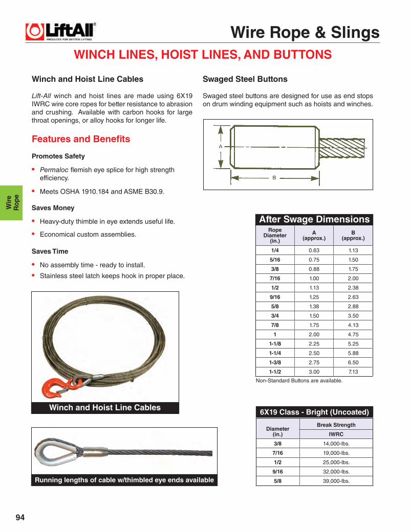
3/8 14,000-lbs.
7/16 19,000-lbs.
1/2 25,000-lbs.
9/16 32,000-lbs.
5/8 39,000-lbs.
WINCH LINES, HOIST LINES, AND BUTTONS
Winch and Hoist Line Cables
Lift-All winch and hoist lines are made using 6X19 IWRC wire core ropes for better resistance to abrasion and crushing. Available with carbon hooks for large throat openings, or alloy hooks for longer life.
Features and Benefi ts
Promotes Safety
• Permaloc fl emish eye splice for high strength effi ciency.
• Meets OSHA 1910.184 and ASME B30.9.
Saves Money
• Heavy-duty thimble in eye extends useful life.
• Economical custom assemblies.
Saves Time
• No assembly time - ready to install.
• Stainless steel latch keeps hook in proper place.
Swaged Steel Buttons
Swaged steel buttons are designed for use as end stops on drum winding equipment such as hoists and winches.
After Swage Dimensions
6X19 Class - Bright (Uncoated)
RopeDiameter
(in.)
A (approx.)
B (approx.)
1/4 0.63 1.13
5/16 0.75 1.50
3/8 0.88 1.75
7/16 1.00 2.00
1/2 1.13 2.38
9/16 1.25 2.63
5/8 1.38 2.88
3/4 1.50 3.50
7/8 1.75 4.13
1 2.00 4.75
1-1/8 2.25 5.25
1-1/4 2.50 5.88
1-3/8 2.75 6.50
1-1/2 3.00 7.13
Non-Standard Buttons are available.
Winch and Hoist Line Cables
Running lengths of cable w/thimbled eye ends available

Wire Rope & Slings
95
Wire
Ro
pe
Note: Specialty ropes are available upon request.
WIRE ROPE
The Nominal Breaking Strength of wire rope should be considered the straight line pull, which will ACTUALLY BREAK a new, UNUSED, rope (with both rope ends fi xed to prevent rotation). The Nominal Breaking Strength of the rope should NEVER BE USED AS ITS WORKING LOAD.
To determine the working load of a wire rope, the MINIMUM or NOMINAL Breaking Strength MUST BE REDUCED by a DESIGN FACTOR. The design factor will vary depending upon the type of machine and installation, and the work permitted. YOU must determine the applicable Design Factor for your use.
For example, a Design Factor of "5" means that the Minimum or Nominal Breaking Strength of the wire rope must be DIVIDED BY FIVE to determine the maximum load that can be applied to the rope system.
Design Factors have been established by OSHA, by ANSI, by ASME, and similar government and industrial organiza-tions.
No wire rope should ever be installed or used without full knowledge and consideration of the Design Factor for the application.
The above is based on the 'Wire Rope Safety Bulletin' pub-lished by the "WIRE ROPE TECHNICAL BOARD."
Rope Diameter
(in.)
Approx.Weight
per Foot(lbs.)
NominalBreakingStrength
(tons)
1/4 0.12 3.40
5/16 0.18 5.27
3/8 0.26 7.55
7/16 0.35 10.2
1/2 0.46 13.3
9/16 0.59 16.8
5/8 0.72 20.6
3/4 1.04 29.4
7/8 1.42 39.8
1 1.85 51.7
1-1/8 2.34 65.0
1-1/4 2.89 79.9
1-3/8 3.50 96.0
1-1/2 4.16 114
1-5/8 4.88 132
1-3/4 5.67 153
1-7/8 6.50 174
2 7.39 198
RopeDia. (in.)
Approx. Weight
per Foot(lbs.)
NominalBreakingStrength
(tons)
3/8 0.25 6.15
7/16 0.35 8.33
1/2 0.45 10.8
9/16 0.58 13.6
5/8 0.71 16.8
3/4 1.02 24.0
7/8 1.39 32.5
1 1.82 42.2
1-1/8 2.30 53.1
WIRE CORE
Extra Improved Plow Steel (EIPS) Higher Capacities
Six Strand Ropes Having 9 to 26 Wires Per Strand
Better Abrasion Resistance
Six Strand Ropes Having 27 to 49 Wires Per Strand
More Flexible
6X19
6X37
19X7
6X19 and 6X37 Class Wire Rope
These high quality wire ropes are available in cut lengths or by the reels.
ROTATION RESISTANT WIRE ROPE
6X19 CLASS
6X37 CLASS

Wire Rope & Slings
Wir
eR
ope
96
CABLE & COMPONENTSGalvanized (GAC) and Stainless Steel (SSAC) Cable
Galvanized Cable Coated with Clear Vinyl (VGAC)Galvanized
CableConstruction
CableDiameter
(in.)
Coatedto
(in.)
Weight per Reel
(lbs.)
StandardLength
(ft./Reel)
Nominal Break Strength
(lbs.)
7X71/16 3/32 7 500 480
3/32 3/16 7 250 920
1/8 3/16 10 250 1,700
7X191/8 3/16 10 250 2,000
3/16 1/4 19 200 4,200
1/4 5/16 28 200 7,000
RopeDia.(in.)
Dimensions(in.) Quantity
Per Bag
WeightPer Bag
(lbs.)A B C
1/8 1.31 0.69 0.25 100 4
3/16 1.31 0.69 0.31 100 4
1/4 1.31 0.69 0.38 100 4
5/16 1.50 0.82 0.44 80 3
3/8 1.63 0.94 0.50 80 4
7X7Cable
Diameter(in.)
Weight per Reel
(lbs.)
StandardLength
(ft./Reel)
Nominal Break Strength(lbs.)
GalvanizedCable (GAC)
StainlessSteel Cable
(SSAC) Type 304
1/16 5 500 480 430
3/32 9 500 920 820
1/8 15 500 1,700 1,500
7X19 3/32 9 500 1,000 920
1/8 15 500 2,000 1,760
5/32 12 250 2,800 2,400
3/16 17 250 4,200 3,700
1/4 25 250 7,000 6,400
5/16 38 200 9,800 9,000
3/8 52 200 14,400 12,000
RopeDiameter
(in.)
Dimensions(in.)
WeightEach(lbs.)A B C
1/4 1.63 0.88 0.44 0.08
5/16 1.88 1.06 0.53 0.14
3/8 2.13 1.13 0.66 0.22
7/16 2.32 1.25 0.75 0.36
1/2 2.75 1.50 0.94 0.51
9/16 2.75 1.50 1.00 0.35
5/8 3.25 1.75 1.03 0.75
3/4 3.75 2.00 1.25 1.47
7/8 4.25 2.25 1.44 1.85
1 4.50 2.50 1.69 3.00
1-1/8 5.13 2.88 1.81 4.00
1-1/4 6.50 3.50 2.19 8.17
1-3/8 & 1-1/2 6.25 3.50 2.56 11.75
1-5/8 8.00 4.00 2.72 17.00
1-3/4 9.00 4.50 2.84 17.75
1-7/8 & 2 12.0 6.00 3.09 25.00
2-1/4 14.0 7.00 3.63 39.50
B
A
C
B
A
C
Heavy Duty Wire Rope Thimbles
Standard Wire Rope Thimbles
Wire Rope & Slings
97
Wire
Ro
pe
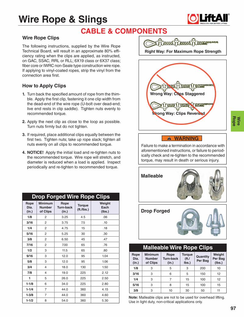
CABLE & COMPONENTSWire Rope Clips
The following instructions, supplied by the Wire Rope Technical Board, will result in an approximate 80% effi -ciency rating when the clips are applied, as instructed, on GAC, SSAC, RRL or RLL; 6X19 class or 6X37 class; fi ber core or IWRC non-Seale type construction wire rope. If applying to vinyl-coated ropes, strip the vinyl from the connection area fi rst.
How to Apply Clips
1. Turn back the specifi ed amount of rope from the thim-ble. Apply the fi rst clip, fastening it one clip width from the dead-end of the wire rope (U-bolt over dead-end; live end rests in clip saddle). Tighten nuts evenly to recommended torque.
2. Apply the next clip as close to the loop as possible. Turn nuts fi rmly but do not tighten.
3. If required, place additional clips equally between the fi rst two. Tighten nuts; take up rope slack; tighten all nuts evenly on all clips to recommended torque.
4. NOTICE! Apply the initial load and re-tighten nuts to the recommended torque. Wire rope will stretch, and diameter is reduced when a load is applied. Inspect periodically and re-tighten to recommended torque.
Failure to make a termination in accordance with aforementioned instructions, or failure to period-ically check and re-tighten to the recommended torque, may result in death or serious injury.
Wrong Way: Clips Reversed
Drop Forged Wire Rope Clips
WARNING
Malleable Wire Rope Clips
Note: Malleable clips are not to be used for overhead lifting. Use in light duty, non-critical applications only.
RopeDia.(in.)
MinimumNumberof Clips
RopeTurn-back
(in.)
Torque(ft./lbs.)
QuantityPer Bag
WeightPer Bag
(lbs.)
1/8 3 5 3 200 10
3/16 3 6 5 150 12
1/4 3 7 15 100 12
5/16 3 8 15 100 15
3/8 3 10 30 50 11
RopeDia. (in.)
MinimumNumberof Clips
RopeTurn-back
(in.)
Torque(ft./lbs.)
WeightEach(lbs.)
1/8 2 3.25 4.5 .06
3/16 2 3.75 7.5 .10
1/4 2 4.75 15 .18
5/16 2 5.25 30 .30
3/8 2 6.50 45 .47
7/16 2 7.00 65 .76
1/2 3 11.5 65 .80
9/16 3 12.0 95 1.04
5/8 3 12.0 95 1.06
3/4 4 18.0 130 1.50
7/8 4 19.0 225 2.12
1 5 26.0 225 2.50
1-1/8 6 34.0 225 2.80
1-1/4 7 44.0 360 4.15
1-3/8 7 44.0 360 4.60
1-1/2 8 54.0 360 5.30
Wrong Way: Clips ReversedWrong Way: Clips Reversed
Right Way: For Maximum Rope Strength
Wrong Way: Clips Staggered
Malleable
Drop Forged
Wire Rope & Slings
Wir
eR
ope
98
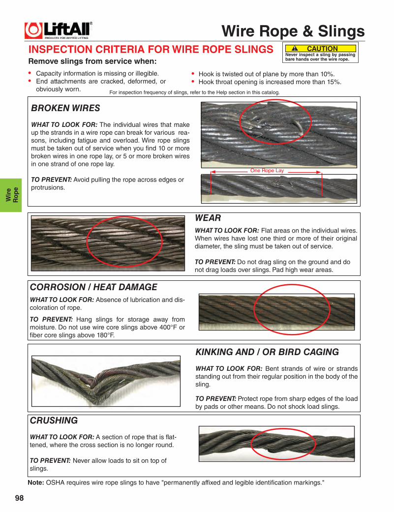
INSPECTION CRITERIA FOR WIRE ROPE SLINGS
BROKEN WIRES
WHAT TO LOOK FOR: The individual wires that make up the strands in a wire rope can break for various rea-sons, including fatigue and overload. Wire rope slings must be taken out of service when you fi nd 10 or more broken wires in one rope lay, or 5 or more broken wires in one strand of one rope lay.
TO PREVENT: Avoid pulling the rope across edges or protrusions.
CORROSION / HEAT DAMAGEWHAT TO LOOK FOR: Absence of lubrication and dis-coloration of rope.
TO PREVENT: Hang slings for storage away from moisture. Do not use wire core slings above 400°F or fi ber core slings above 180°F.
CRUSHING
WHAT TO LOOK FOR: A section of rope that is fl at-tened, where the cross section is no longer round.
TO PREVENT: Never allow loads to sit on top of slings.
WEARWHAT TO LOOK FOR: Flat areas on the individual wires. When wires have lost one third or more of their original diameter, the sling must be taken out of service.
TO PREVENT: Do not drag sling on the ground and do not drag loads over slings. Pad high wear areas.
KINKING AND / OR BIRD CAGING
WHAT TO LOOK FOR: Bent strands of wire or strands standing out from their regular position in the body of the sling.
TO PREVENT: Protect rope from sharp edges of the load by pads or other means. Do not shock load slings.
Remove slings from service when:
• Capacity information is missing or illegible. • End attachments are cracked, deformed, or
obviously worn. For inspection frequency of slings, refer to the Help section in this catalog.
Note: OSHA requires wire rope slings to have "permanently affi xed and legible identifi cation markings."
One Rope Lay
CAUTION Never inspect a sling by passing bare hands over the wire rope.
• Hook is twisted out of plane by more than 10%.• Hook throat opening is increased more than 15%.

Wire Rope & Slings
99
Wire
Ro
pe
SLING WEIGHTS
* Zero Base Weight accounts for the additional rope and sleeves required to form two standard eyes.
TO ESTIMATE SLING WEIGHTS
Sling Weight = (Length x Per Foot Weight) + Zero Base Weight + Fitting Weights
RopeDia. (in.)
ZeroBase
Weight*(lbs.)
Per Foot
Weight(lbs.)
ThimbledEye
Wt. Ea.(lbs.)
AlloyEye
HookWt. Ea.
(lbs.)
CrescentThimbleWt. Ea.(lbs.)
Slip ThruThimbleWt. Ea.(lbs.)
SlidingChokerHook
Wt. Ea.(lbs.)
1/4 0.31 0.12 0.08 0.63 0.50 1.3 1.3
5/16 0.47 0.18 0.14 0.63 0.50 1.3 1.3
3/8 0.73 0.26 0.22 0.85 0.50 1.3 1.3
7/16 1.3 0.35 0.36 1.4 0.50 1.5 1.9
1/2 1.7 0.46 0.51 1.9 0.75 1.5 1.9
9/16 3.1 0.59 0.51 3.7 0.75 1.5 1.9
5/8 3.5 0.72 0.75 3.7 1.2 3.4 4.0
3/4 5.7 1.0 1.5 7.3 2.0 3.4 4.5
7/8 8.9 1.4 1.9 15 3.3 5.6 10
1 13 1.9 3.0 15 3.8 5.6 10
1-1/8 18 2.3 4.0 22 5.0 8.6 26
1-1/4 25 2.9 8.2 22 6.8 8.6 26
1-3/8 32 3.5 12 38 8.0 10 50
1-1/2 41 4.2 12 38 8.0 10 50
1-3/4 65 5.7 18 60 17 18 −
2 99 7.4 25 105 22 53 −
2-14 169 9.4 40 148 39 70 −
2-1/2 278 12 − − 39 126 −

Wire Rope & Slings
Wir
eR
ope
100
RopeDia.(in.)
*ZeroBase
Weight(lbs.)
PerFoot
Weight(2-Legs)
*ZeroBase
Weight(lbs.)
Per Foot Weight(lbs.)
(3-Legs)
*ZeroBase
Weight(lbs.)
Per Foot Weight(lbs.)
(4-Legs)
1/4 2.8 .23 2.8 .35 4.7 .46
5/16 3.2 .36 5.7 .54 6.9 .72
3/8 5.8 .52 7.5 .78 12 1.0
7/16 8.1 .70 14 1.0 17 1.4
1/2 10 .92 17 1.4 26 1.8
9/16 20 1.2 27 1.8 39 2.4
5/8 21 1.4 34 2.2 42 2.9
3/4 38 2.1 60 3.1 85 4.2
7/8 58 2.8 89 4.3 121 5.7
1 76 3.7 114 5.6 171 7.4
1-1/8 108 4.7 163 7.0 250 9.4
1-1/4 131 5.8 210 8.7 296 12
1-3/8 197 7.0 320 11 − −
1-1/2 230 8.3 350 13 − −
1-3/4 380 11 − − − −
2 550 15 − − − −
TO ESTIMATE BRIDLE SLING WEIGHTS
4-Leg Bridle3-Leg Bridle2-Leg Bridle
SLING WEIGHTS
* Zero Base Weight includes Oblong Link, Thimbled Eyes and Sling Hooks
ACKNOWLEDGEMENT
Lift-All wire rope slings and rated capacities comply with all OSHA, ASME B30.9, and Wire Rope Technical Board publications. Portions of this section of the cat-alog were taken from the Wire Rope Sling User’s Manual with the permission of the Wire Rope Technical Board and the American Iron and Steel Institute.
Sling Weight = (Length x Per Foot Weight) + Zero Base Weight