Embed Size (px)
Citation preview

Pump DivisionIDP Pacific Worthington Jeumont-Schneider Pumps Byron Jackson Durco Pleuger
INSTALLATION AND MAINTENANCE INSTRUCTIONS
MENLife-timelubricatedbearings
NOT 04 96 356 V06 AN

MEN NOT 0496356 V06 AN
Pump Division Page: 2 - 48
INSTALLATION AND MAINTENANCE INSTRUCTIONSThe information contained in this document is confidential. It must not be disclosed or copied without our written consent.
Dear Customer,
You have chosen a pump from FLOWSERVE for your plant, thank you for trusting us.The information contained in this leaflet will allow you to benefit from a motor pump inthe best conditions of installation, operation and maintenance, therefore we ask you totake enough time to read it.
Your FLOWSERVE agent is at your disposal for any further information about yourequipment (installation, running, additional equipments). Do not hesitate to contact him ifneeded.
__________________________________
Traduction en Anglais du manuel d'installation et d'entretien NOT 04 96 356 V06 FR
Translation of the instruction book NOT 04 96 356 V06 FR

MEN NOT 0496356 V06 AN
Pump Division Page: 3 - 48
INSTALLATION AND MAINTENANCE INSTRUCTIONSThe information contained in this document is confidential. It must not be disclosed or copied without our written consent.
TABLE OF CONTENTS
1. SAFETY ...........................................................................................................................................................5
2. PUMP DESCRIPTION...................................................................................................................................9
2.1 Coverage charts.......................................................................................................................................11
3. HANDLING...................................................................................................................................................15
3.1 General instructions concerning handling...............................................................................................153.2 Pump masses ...........................................................................................................................................163.3 Slinging of motor pumps units................................................................................................................17
4. PREPARATION BEFORE INSTALLATION...........................................................................................18
4.1 Unpacking and Inspection.......................................................................................................................184.2 Storage ....................................................................................................................................................18
5. INSTALLATION ..........................................................................................................................................19
5.1 Location ..................................................................................................................................................195.2 Foundation ..............................................................................................................................................195.3 Alignment................................................................................................................................................215.4 Suction and discharge pipework .............................................................................................................225.5 Electrical Connections ............................................................................................................................27
6. STARTING AND RUNNING ......................................................................................................................28
6.1 Priming of a flooded pump .....................................................................................................................286.2 Priming of a sump suction pump.............................................................................................................286.3 Bring controls and preparation before the first starting and after each service call ................................296.4 First pump start-up ..................................................................................................................................306.5 Running...................................................................................................................................................326.6 Stopping and restarting in continuous running .......................................................................................336.7 Shutdown ................................................................................................................................................33
MEN NOT 0496356 V06 AN
Pump Division Page: 4 - 48
INSTALLATION AND MAINTENANCE INSTRUCTIONSThe information contained in this document is confidential. It must not be disclosed or copied without our written consent.
7. FAULT FINDING CHART..........................................................................................................................34
8. MAINTENANCE...........................................................................................................................................36
8.1 Generalities about inspections and maintenance . ...................................................................................368.2 Maintenance Schedule.............................................................................................................................378.3 Standard maintenance..............................................................................................................................378.4 Maintenance of the shaft seal system ......................................................................................................37
9 REPAIR OF THE PUMP .............................................................................................................................39
9.1 Dismantling of a MEN pump ..................................................................................................................409.2 Reassembly of a MEN pump...................................................................................................................419.3 Recommended screw torques..................................................................................................................449.4 Mechanical seal .......................................................................................................................................44
10. RECOMMENDED SPARES........................................................................................................................46
10.1 Recommended Spares .............................................................................................................................4610.2 General arrangement drawing .................................................................................................................4710.3 Sectional drawing parts list .....................................................................................................................48

MEN NOT 0496356 V06 AN
Pump Division Page: 5 - 48
INSTALLATION AND MAINTENANCE INSTRUCTIONSThe information contained in this document is confidential. It must not be disclosed or copied without our written consent.
1. SAFETY
This operation manual gives basic instructions which are to be observed during installation, operationand maintenance of the pump. It is therefore imperative that this manual be read by the responsiblepersonnel/operator prior to assembly and commissioning. It is always to be kept available at theinstallation site.
It is not only the general safety instructions contained under this main heading safety that are to beobserved but also the specific information provided under the other main headings.
Qualifications and training of personnel
The personnel responsible for operation, maintenance, inspection and assembly must be adequatelyqualified. Scope of responsibility and supervision of the personnel must be exactly defined by the plantoperator. If the staff does not have the necessary knowledge they must be trained and instructed, whichmay be performed by the machine manufacturer or supplier on behalf of the plant operator. Moreover,the plant operator is to make sure that the contents of the operating manual are fully understood by thepersonnel.
Hazards in the event of non-compliance with the safety instructions
Non compliance with the safety instructions may produce a risk to the personnel as well as to theenvironment and the machine and results in a loss of any right to claim damages.
For example, non-compliance may involve the following hazards :
- Failure of important functions of the machines/plant- Failure of specified procedures of maintenance and repair- Exposure of people to electrical, mechanical and chemical hazards- Endangering the environment owing to hazardous substances being released.
Gloves and safety boots are compulsory in all the plants and, no matter how small the risk of an objectfalling, a safety helmet is recommended.
Never exceed the limits of flow rate, pressure and temperature specified in this leaflet. It is possiblethat the equipment may not withstand and create material or physical damages.
Unauthorized alterations and production of spare parts
Any modification may be made to the machine only after being authorized by the manufacturer. Usingspare-parts and accessories authorized by the manufacturer is in the interest of safety. Use of otherparts may exempt the manufacturer from any liability.

MEN NOT 0496356 V06 AN
Pump Division Page: 6 - 48
INSTALLATION AND MAINTENANCE INSTRUCTIONSThe information contained in this document is confidential. It must not be disclosed or copied without our written consent.
Pump noise
When the pump noise level exceeds 85 dBA attention must be given to prevailing Health and SafetyLegislation, to limit the exposure of plant operating personnel to excessive noise. The usual approach isto control exposure time to the noise or to enclose the machine to reduce emitted sound to thesurroundings.
Pump noise level is dependent on a number of factors :
the type of motor fitted, the operating capacity, pipework design, and acoustic characteristics of thebuilding.
The noise levels specified in the table below give a general guide to the levels to expect.
2900 min-1 2900 min-1 1450 min-1 1450 min-1
MOTORSIZEkW
PUMP &MOTOR
dBA
PUMPONLYdBA
PUMP &MOTOR
dBA
PUMPONLYdBA
<0.55 64 62 63 620.75 67 62 63 621.1 67 64 65 641.5 70 66 66 662.2 71 68 68 683 74 70 70 704 75 71 71 71
5.5 83 73 72 717.5 83 74 73 7211 84 76 74 7315 85 77 75 74
18.5 85 79 76 7522 85 79 77 7530 93 81 80 7637 93 82 80 7645 93 83 80 7655 95 84 82 7775 95 86 83 7890 95 86 85 78110 95 87 86 79132 95 87 86 79160 96 88 86 79
The dBA values are based on the noisiest ungeared electric motors which are likely to be encountered,they are Sound Pressure levels at 1 meter from the directly driven pump, for "free field over areflecting plane".
MEN NOT 0496356 V06 AN
Pump Division Page: 7 - 48
INSTALLATION AND MAINTENANCE INSTRUCTIONSThe information contained in this document is confidential. It must not be disclosed or copied without our written consent.
If a pump unit only has been purchased, for fitting with your own driver, then the "pump only" noiselevels from the table should be combined with the level for the driver obtained from the supplier.Consult a Noise Specialist for this calculation.
In areas where the staff has to intervene, remember that when the level of the sound pressure is :
- Below 70 dBA : It is not necessary to take special precautions.
- Above 70 dBA : People working continuously in the machine room mustbe supplied with protective devices against noise.
- Below 85 dBA : No particular measures need to be taken for casualvisitors staying in the room during a limited period.
- Above 85 dBA : The room must be considered as a dangerous areabecause of the noise and a warning sign must be fixed ateach entry warning the people coming into the room,even for a short period, that they must wear hearingprotection.
- Above 105 dBA : Special hearing protection adapted to this noise level andto the spectral noise components must be installed and awarning sign to this effect erected at each entry. The staffin the room must wear ear protection.
Make sure that the noise which travels through the walls and windows does not generate too high noiselevels in the machine room's surroundings.

MEN NOT 0496356 V06 AN
Pump Division Page: 8 - 48
INSTALLATION AND MAINTENANCE INSTRUCTIONSThe information contained in this document is confidential. It must not be disclosed or copied without our written consent.
Pumps for Food Use or Potable Water
If the pump has not been specifically ordered for a food or drinking water application it must not beused for these type of applications. If it has been ordered for this type of application the followingrecommendations are to be followed.
Cleaning prior to operation
Pumps that are to be used for a food or drinking water application should be cleaned before being putinto initial operation and after the installation of spare parts that are in contact with the liquid.
The cleaning should include at least the following steps :
Caustic rinse for 20-25 minutes at 80°C.Clean water rinse for 20-25 minutes at 80°C.Acid rinse for 15-20 minutes at 80°C.Clean water rinse for 20-25 minutes at 80°C.
The flow rate during this period must be at least 100 % of the maximum operation flow.
The concentrations of the caustic and acid rinses should be as per the supplier's recommendations.
The above procedure is a general procedure. The user should ajust the conditions based on theirexperience. Cleaning once the pump has been commissioned will depend on the application andoperating conditions. The user must ensure that the cleaning procedures are suitable for the applicationand operating conditions.

MEN NOT 0496356 V06 AN
Pump Division Page: 9 - 48
INSTALLATION AND MAINTENANCE INSTRUCTIONSThe information contained in this document is confidential. It must not be disclosed or copied without our written consent.
2. PUMP DESCRIPTION
The MEN pump is a single-stage centrifugal pump with an axial inlet and a vertical outlet. Thedimensions of the volute pump casing, of the suction and discharge diameters, of the settlement feet aswell as of the shaft end diameter and position correspond to standards : DIN 24255 and NF EN 733.
! The pump must be stored in a non explosive, ventilated location, sheltered from badweather, dust and vibrations.
The reliability of the delivered machine can only be ensured if it is used according to the conditionsgiven in this manual. The maximum values specified in this manual must never be exceeded.
∗ Maximum working pressure at discharge 16 bars∗ Maximum working pressure at suction 10 bars∗ Maximum pumped fluid temperature :
- Gland packing ≤ 105° Celsius- Mechanical seal ≤ 120° Celsius
∗ Minimum pumped fluid temperature - 10° Celsius∗ Maximum ambient temperature 40° Celsius∗ Maximum solid suspension 50 g/m3
∗ Density 1∗ Viscosity 1 mm2/s∗ Rotation speed (frequency 50 Hz) :
- MEN 1450 min-1
- MEN 2900 min-1
∗ Rotation speed (frequency 60 Hz) :- MEN 1750 min-1 (ou) 3500 min-1
! The maximum speed is shown on the pump nameplate.
MEN NOT 0496356 V06 AN
Pump Division Page: 10 - 48
INSTALLATION AND The information contained in this document is
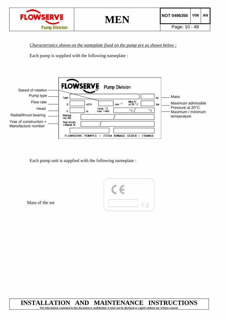
Characteristics shown on the nameplate fixed on the pump are as shown below :
Each pump is supplied with the following nameplate :
Each pump unit is supplied with the following nameplate :
Mass of the set
Pump typeSpeed of rotation
Flow rate
Year of construction +Manufacture number
Head
Radial/thrust bearing
Mass
Maximum admissiblePressure at 20°CMaximum / minimumtemperature
MAINTENANCE INSTRUCTIONSconfidential. It must not be disclosed or copied without our written consent.

MEN NOT 0496356 V06 AN
Pump Division Page: 11 - 48
INSTALLATION AND MAINTENANCE INSTRUCTIONSThe information contained in this document is confidential. It must not be disclosed or copied without our written consent.
2.1 Coverage charts
2.1.1 1450 min-1 (50Hz) : coverage charts (Q,H)

MEN NOT 0496356 V06 AN
Pump Division Page: 12 - 48
INSTALLATION AND MAINTENANCE INSTRUCTIONSThe information contained in this document is confidential. It must not be disclosed or copied without our written consent.
2.1.2 2900 min-1 (50Hz) : coverage charts (Q,H)

MEN NOT 0496356 V06 AN
Pump Division Page: 13 - 48
INSTALLATION AND MAINTENANCE INSTRUCTIONSThe information contained in this document is confidential. It must not be disclosed or copied without our written consent.
2.1.3 1750 min-1 (60 Hz) : coverage charts(Q,H)

MEN NOT 0496356 V06 AN
Pump Division Page: 14 - 48
INSTALLATION AND MAINTENANCE INSTRUCTIONSThe information contained in this document is confidential. It must not be disclosed or copied without our written consent.
2.1.4 3500 min-1 (60 Hz) : coverage charts(Q,H)

MEN NOT 0496356 V06 AN
Pump Division Page: 15 - 48
INSTALLATION AND MAINTENANCE INSTRUCTIONSThe information contained in this document is confidential. It must not be disclosed or copied without our written consent.
3. HANDLING
3.1 General instructions concerning handling
Boxes, crates, pallets or cartons may be unloaded using fork lift vehicles or slings dependent ontheir size and construction.
To lift heavy pieces above 30kg, use a winch adapted to the mass and in accordance with thecurrent local regulations.
To lift machines or pieces with one or several suspension rings, only use hooks and chains incompliance with the local regulations concerning safety. Never put cables, chains or ropesdirectly on or in the suspension rings. Cables, chains or lifting ropes must never presentexcessive bending.
Never bend the lifting hooks, suspension rings, chains, etc... which should only be made toendure stresses within calculated limits. Remember that the capacity of a lifting device decreaseswhen the direction of the lifting force direction makes an angle with the device axis.
To increase the safety and the efficiency of the lifting device, all the lifting elements must be asperpendicular as possible. If necessary a lifting beam can be placed between the winch and theload.
When heavy pieces are lifted up, never stay or work under the load or in the area which could bein the path of the load if it were to swing or fall away. Never leave a load hanging from a winch.The acceleration or the slowing-down of lifting equipment must stay in the safety limits for thestaff.
A winch must be positionned in such a way that the load will be raised perpendicularly. Wherepossible necessary precautions must be taken to avoid the swing of the load, using for exampletwo winches making approximately the same angle, below 30°, with the vertical.

MEN NOT 0496356 V06 AN
Pump Division Page: 16 - 48
INSTALLATION AND MAINTENANCE INSTRUCTIONSThe information contained in this document is confidential. It must not be disclosed or copied without our written consent.
3.2 Pump masses
All masses are in kg
PUMP TYPEPUMPMASS
MASS OFPUMP CASING
MASS OFCASING COVER
MEN 50-32-125 30MEN 50-32-160 35MEN 50-32-200 38MEN 50-32-200L 43MEN 65-40-125 33MEN 65-40-160 36MEN 65-40-200L 44MEN 65-40-250 51 Mass < 30 kgMEN 65-40-250L 58MEN 65-50-125 35MEN 65-50-160 44 Mass < 30 kgMEN 65-50-200L 48MEN 65-50-250L 57MEN 80-65-125 39MEN 80-65-160 46MEN 80-65-200L 55MEN 80-65-250L 85 32MEN 80-65-315 105 43MEN 100-80-160 49 31MEN 100-80-200L 78 33MEN 100-80-250L 91 40MEN 100-80-315 113 47MEN 125-100-200L 94 43MEN 125-100-250L 100 50MEN 125-100-315 123 52MEN 125-100-315L 125 56MEN 125-100-400 185 72 39MEN 125-100-400L 189 75 40MEN 150-125-250L 120 72 Mass < 30 kgMEN 150-125-315L 200 73 30MEN 150-125-400L 230 88 38MEN 200-150-315L 203 103 30MEN 200-150-400L 240 104 38
All motors (for masses see the motor description plate) must be handled with a winch.
! For masses above 30 kg, manual handling is forbidden.

MEN NOT 0496356 V06 AN
Pump Division Page: 17 - 48
INSTALLATION AND MAINTENANCE INSTRUCTIONSThe information contained in this document is confidential. It must not be disclosed or copied without our written consent.
3.3 Slinging of motor pumps units
! Use handling means in accordance with motor pump unit mass mentioned on the CEplate. For the masses of the pumps bare end of shaft see table § 3.2 and nameplate.
To avoid distortion, lift up motor pump unit as shown
Motor pump unit
Bareshaft pump
! When handling always wear gloves, safety boots and an industrial safety helmet.
! For masses above 30 kg, manual handling is forbidden.

MEN NOT 0496356 V06 AN
Pump Division Page: 18 - 48
INSTALLATION AND MAINTENANCE INSTRUCTIONSThe information contained in this document is confidential. It must not be disclosed or copied without our written consent.
4. PREPARATION BEFORE INSTALLATION
4.1 Unpacking and Inspection
The pump should be checked against the delivery advice note and any damage or shortagereported immediately to Flowserve. Any crate/carton/wrappings should be checked for any spareparts or accessories which may be packed with the pump.
4.2 Storage
Store the pump in a clean, dry location away from vibration. Leave piping connection covers inplace to keep dirt and other foreign material out of pump casing. Turn pump once a week toprevent brinelling of the bearings and the seal faces, if fitted, from sticking.
The pump may be stored as above for up to 6 months. Consult FLOWSERVE for preservativeactions when a longer storage period is needed.
MEN NOT 0496356 V06 AN
Pump Division Page: 19 - 48
INSTALLATION AND MAINTENANCE INSTRUCTIONSThe information contained in this document is confidential. It must not be disclosed or copied without our written consent.
5. INSTALLATION
5.1 Location
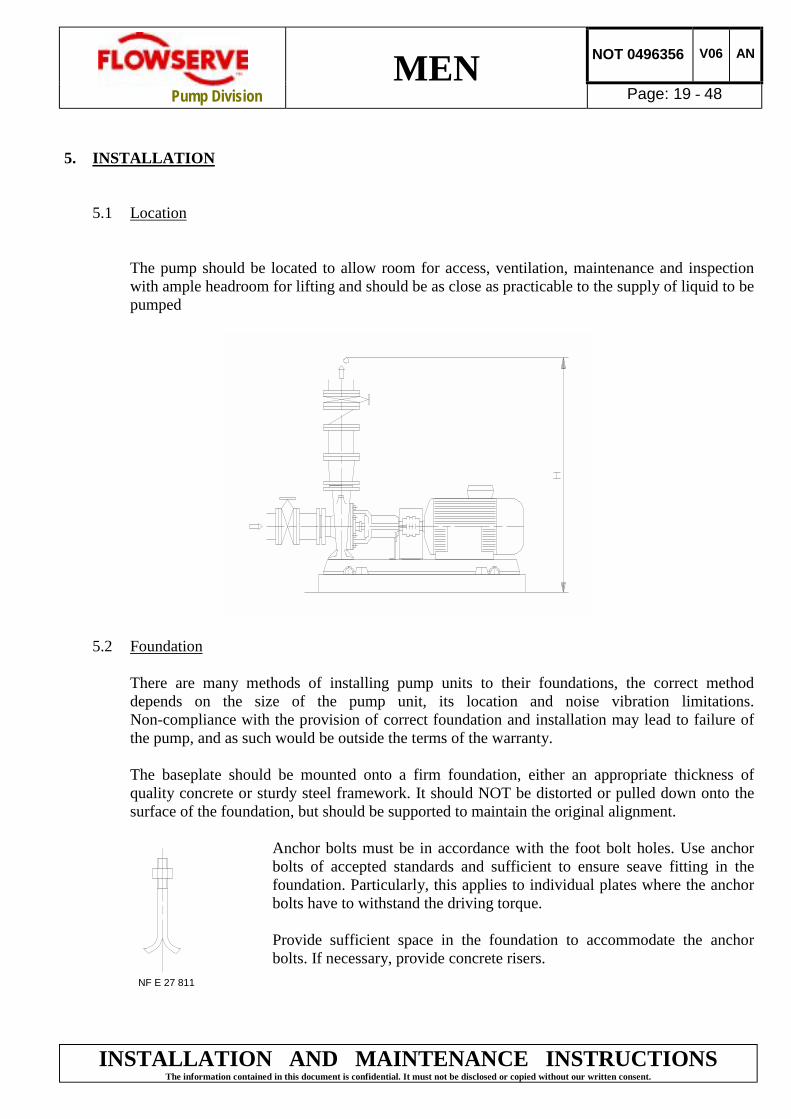
The pump should be located to allow room for access, ventilation, maintenance and inspectionwith ample headroom for lifting and should be as close as practicable to the supply of liquid to bepumped
5.2 Foundation
There are many methods of installing pump units to their foundations, the correct methoddepends on the size of the pump unit, its location and noise vibration limitations.Non-compliance with the provision of correct foundation and installation may lead to failure ofthe pump, and as such would be outside the terms of the warranty.
The baseplate should be mounted onto a firm foundation, either an appropriate thickness ofquality concrete or sturdy steel framework. It should NOT be distorted or pulled down onto thesurface of the foundation, but should be supported to maintain the original alignment.
Anchor bolts must be in accordance with the foot bolt holes. Use anchorbolts of accepted standards and sufficient to ensure seave fitting in thefoundation. Particularly, this applies to individual plates where the anchorbolts have to withstand the driving torque.
Provide sufficient space in the foundation to accommodate the anchorbolts. If necessary, provide concrete risers.
NF E 27 811

MEN NOT 0496356 V06 AN
Pump Division Page: 20 - 48
INSTALLATION AND MAINTENANCE INSTRUCTIONSThe information contained in this document is confidential. It must not be disclosed or copied without our written consent.
Usually the pump and its drive are mounted on a common baseplate. If not, individual baseplatesunderneath each machine foot shall be installed. Baseplates are to be fully grouted.
5.2.1 Setting the baseplate for anchoring- Clean the foundation surface thoroughly.- Put shims on the foundation surface (approx 20-25 mm thick), one on each side of the
bolt hole (as an alternative, levelling srews can be used).
- Lay the baseplate and level in both directions with extra shims. The baseplate should belevel to within 0,5 mm per 1 m
5.2.2 Baseplate grouting
Prepare the site for grouting. Before grouting clean the foundation surface thoroughly andprovide external barriers as shown :
Barriers
Prepare grouting product (concrete, resin) in accordance with manufacturers' instructions.
MEN NOT 0496356 V06 AN
Pump Division Page: 21 - 48
INSTALLATION AND MAINTENANCE INSTRUCTIONSThe information contained in this document is confidential. It must not be disclosed or copied without our written consent.
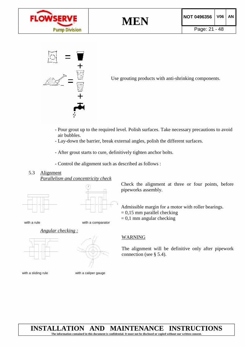
Use grouting products with anti-shrinking components.
- Pour grout up to the required level. Polish surfaces. Take necessary precautions to avoidair bubbles.
- Lay-down the barrier, break external angles, polish the different surfaces.
- After grout starts to cure, definitively tighten anchor bolts.
- Control the alignment such as described as follows :
5.3 AlignmentParallelism and concentricity check
Check the alignment at three or four points, beforepipeworks assembly.
Admissible margin for a motor with roller bearings.= 0,15 mm parallel checking= 0,1 mm angular checking
Angular checking :WARNING
The alignment will be definitive only after pipeworkconnection (see § 5.4).
with a rule with a comparator
with a sliding rule with a caliper gauge

MEN NOT 0496356 V06 AN
Pump Division Page: 22 - 48
INSTALLATION AND MAINTENANCE INSTRUCTIONSThe information contained in this document is confidential. It must not be disclosed or copied without our written consent.
If necessary, improve the machine alignment :
→ Complete unit mounted on common baseplate :
The machines are first aligned accurately in our workshops. Usually, any misalignmentobserved on-site is due to a wrong adjustment under the baseplate (disturbed during transportor because of forces excerted by the pipework). It is only necessary to rectify the adjustmentunder baseplate. If it proves to be insufficient, modify the motor and the pipeworksadjustment.
→ Pump and motor mounted on individual baseplates :
Machines are (or must be) first mounted on their own baseplate in the workshop. Once the pumpis set, it will be regarded as the fixed piece. Any alignment necessary shall be carried out on themotor.
! Never connect the electric motor before the setting has been completely finished.
5.4 Suction and discharge pipework
The dimensions of the pipes do not directly depend on suction and discharge diameters of thepump.
- First, choose a flow speed < 2m/s at suction, and about 3 m/s at discharge.
- Take into account the available NPSH which must be superior to the required NPSH of thepump.
Never use pump as a support for piping.Do not mount expansion joints in such a way that their force, due to internal pressure, may act onthe pump flange.
Maximum forces and moments allowed on the pump flanges vary with the pump size and type.These external strains may cause misalignment, hot bearings, worn couplings, vibrations and thepossible failure of the pump casing.
When designing the pipes (§ 5.4.1, § 5.4.2, § 5.4.3) take necessary precautions in order not toexceed maximum allowed strains.

MEN NOT 0496356 V06 AN
Pump Division Page: 23 - 48
Forces and moments applied to the pump flanges must never exceed the values shown in thetable below :
MENPump
SuctionDNA
DischargeDNR Forces (daN) Moments
(mdaN.)(mm) (mm) Fv max Fh max Σ Mt max
50-32-125 50 32 125 95 2050-32-160 50 32 125 95 1750-32-200 50 32 125 95 1750-32-200L 50 32 125 95 1765-40-125 65 40 135 100 2265-40-160 65 40 135 100 2265-40-200L 65 40 135 100 2065-40-250 65 40 135 100 2565-40-250L 65 40 135 100 2565-50-125 65 50 135 100 2265-50-160 65 50 135 100 2265-50-200L 65 50 135 100 2065-50-250L 65 50 135 100 2580-65-125 80 65 145 105 2780-65-160 80 65 145 105 2780-65-200L 80 65 145 105 2780-65-250L 80 65 145 105 2780-65-315 80 65 145 105 27100-80-160 100 80 180 125 47100-80-200L 100 80 180 125 47100-80-250L 100 80 180 125 47100-80-315 100 80 180 125 47125-100-200L 125 100 320 190 95125-100-250L 125 100 330 200 102125-100-315 125 100 310 185 92125-100-315L 125 100 310 185 92125-100-400 125 100 285 170 82125-100-400L 125 100 285 170 82150-125-250L 150 125 450 290 155150-125-315L 150 125 415 260 140150-125-400L 150 125 410 255 137200-150-315L 200 150 500 325 175200-150-400L 200 150 500 325 175
INSTALLATION AND MAINTENANCE INSTRUCTIONSThe information contained in this document is confidential. It must not be disclosed or copied without our written consent.
Forces and moments values are applied to the wholeflanges and not flange by flange. For their sharing out onthe pump flanges, refer to standard NFE 44 - 145.

MEN NOT 0496356 V06 AN
Pump Division Page: 24 - 48
INSTALLATION AND MAINTENANCE INSTRUCTIONSThe information contained in this document is confidential. It must not be disclosed or copied without our written consent.
5.4.1 Design of a flooded suction line
The suction line must be as short and direct as possible, never mount an elbow directly onthe inlet flange of the pump.
Flooded suction configuration
Valve
Non-return valve
Coupling
Motor
Coupling guard
Baseplate
Continuous flowvalve
- Avoid sharp elbows or sudden narrowings. Use convergents ≤ 20° (total angle).
- Arrange the pipework so that there are no air pockets (no bulges).
- If high points cannot be avoided in suction line, provide them with air relief cocks.
- If a strainer is necessary, its net area should be three or four times the area of the suction pipe.
- If an inlet valve is necessary, choose a model with direct crossing.
! Do not tighten flanges before the final check (see § 5.4.4).

MEN NOT 0496356 V06 AN
Pump Division Page: 25 - 48
INSTALLATION AND MAINTENANCE INSTRUCTIONSThe information contained in this document is confidential. It must not be disclosed or copied without our written consent.
5.4.2 Design of a suction lift line
The inlet pipe must be as short and as direct as possible, never place an elbow directly onthe pump inlet nozzle.
Sump suction configuration
Valve
Non-return valveCoupling
Motor
Coupling guard
Immersionsufficient Baseplate: I
≥ I 3 x D
- Avoid sharp elbows or sudden narrowings. Use convergents ≤ 20° (total angle) withupright generating.
- Arrange that the suction pipework is inclined upwards towards the pump ensuring thatthere are no peaks.
- If a foot valve is necessary, do not oversize it because it would generate pulsations(valve beating).
! Do not tighten flanges before the final check (see § 5.4.4).

MEN NOT 0496356 V06 AN
Pump Division Page: 26 - 48
INSTALLATION AND MAINTENANCE INSTRUCTIONSThe information contained in this document is confidential. It must not be disclosed or copied without our written consent.
5.4.3 Design of a discharge line
- If discharge line is provided with a divergent, its total angle will be between 7° and 12°.
- Install the discharge valve after the non-return valve downstream.
The non-return valve will be set in the discharge pipe to protect the pump from anyexcessive pressure surge and from reverse rotation.
If necessary, a control manometer can be connected on the pipework.
Control manometer
! Do not tighten flanges before the final check (see § 5.4.4).

MEN NOT 0496356 V06 AN
Pump Division Page: 27 - 48
INSTALLATION AND MAINTENANCE INSTRUCTIONSThe information contained in this document is confidential. It must not be disclosed or copied without our written consent.
5.4.4 Final check and completion of installation
- Check the tightening of anchor boltsTighten them if necessary !
- Check that protective covers on suction and discharge flanges are removed
- Check that holes of pipework flanges are parallel and correspond to those of the pump.
- Tighten suction and discharge flanges !
- Check the alignment pump-motor according to the procedure § 5.3.Rectify if necessary by adjusting the motor only !
- Check by hand that the pump turns freely.A binding indicates a distortion of the pump, which is due to excessive pipes strains. Ifnecessary the pipework design must be re-examined !
- If it provided, connect auxiliary pipe systems (hydraulic, pneumatic, sealing system).
- Control tightness and functionality of auxiliary pipings.
5.5 Electrical Connections
Electrical connections should be made by a qualified electrician in accordance with the relevantlocal regulations.
The motor must be wired up in accordance with the motor manufacturer's instructions (normallysupplied within the terminal box) including any temperature, earth leakage, current and otherprotective devices as appropriate. The identification nameplate should be checked to ensure thepower supply is appropriate.
A device to provide emergency stopping shall be fitted.
Carry out the ground connections according to the current local regulations.
! To avoid any risk of jamming, the direction of rotation will be checked after primingof the pump (§ 6.1, 6.2) and before the first start (§ 6.4).
MEN NOT 0496356 V06 AN
Pump Division Page: 28 - 48
INSTALLATION AND MAINTENANCE INSTRUCTIONSThe information contained in this document is confidential. It must not be disclosed or copied without our written consent.
6. STARTING AND RUNNING
These operations must be carried out by personnel with approved qualifications
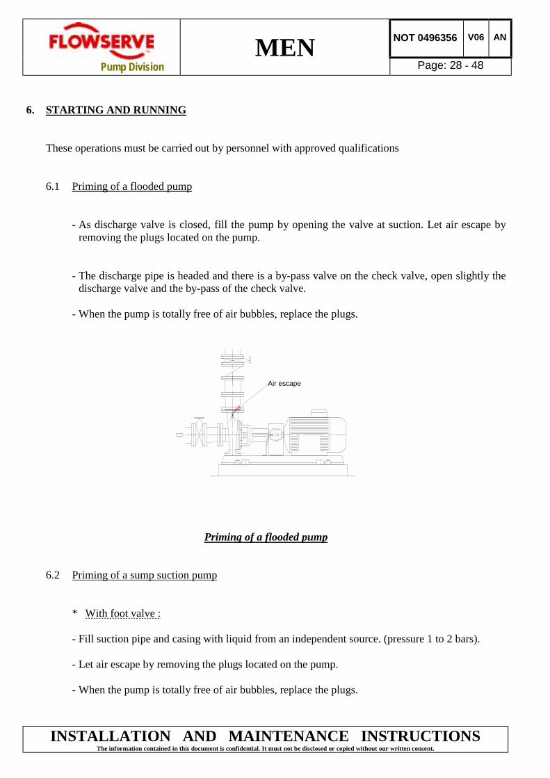
6.1 Priming of a flooded pump
- As discharge valve is closed, fill the pump by opening the valve at suction. Let air escape byremoving the plugs located on the pump.
- The discharge pipe is headed and there is a by-pass valve on the check valve, open slightly thedischarge valve and the by-pass of the check valve.
- When the pump is totally free of air bubbles, replace the plugs.
Air escape
Priming of a flooded pump
6.2 Priming of a sump suction pump
* With foot valve :
- Fill suction pipe and casing with liquid from an independent source. (pressure 1 to 2 bars).
- Let air escape by removing the plugs located on the pump.
- When the pump is totally free of air bubbles, replace the plugs.

MEN NOT 0496356 V06 AN
Pump Division Page: 29 - 48
INSTALLATION AND MAINTENANCE INSTRUCTIONSThe information contained in this document is confidential. It must not be disclosed or copied without our written consent.
EXTERNAL SOURCE
Air escape
Priming of sump suction pump with foot valve
Without foot valve :
- Priming may be accomplished by means of venting system.
NOTE : Foot valves are not recommended when the pumped liquid has suspended solidparticles. They may lodge between foot valve seat and shutter.
6.3 Bring controls and preparation before the first starting and after each service call
Necessarily :
*Check the tightening of the different plugs.
* Check that the gland lightly tightens the packing rings.
! Risk of seal ring overheating.
* Check the direction of rotation of the motor. Refer to the rotation arrow of the pump.
! Install all protection systems and more particularly the coupling guard and theshieldgrid (reference 9610) of the bearing.
* Open all suction valves (if existing)
* Close the outlet valve and the bypass valve* Ensure inlet pipe and pump casing are completely full of liquid.

MEN NOT 0496356 V06 AN
Pump Division Page: 30 - 48
INSTALLATION AND MAINTENANCE INSTRUCTIONSThe information contained in this document is confidential. It must not be disclosed or copied without our written consent.
Safety instructions when the pump is running.
If hot or freezing components of the machine can present a danger to operators, they must beshielded to avoid accidental contact. If a 100% protection is not possible, the machine accessmust be confined to the maintenance staff only.
! If the temperature is greater than 80°Celsius, a warning plate must be clearly placedon the pump.
It is strictly forbidden to open switch cupboards, switch boxes, or all other live electricequipment. If it is necessary to open them in order to take readings, to carry out tests oradjustments for example, only a skilled technician may do them with adapted tools. Make surethat physical protection against electrical risks are used.
6.4 First pump start-up
! Suction valves must be fully open when pump is running. Never run the pump dry, itwill cause damage.
Start motor and check outlet pressure.
If pressure is satisfactory, slowly OPEN outlet valve
Do not run the pump with the outlet valve closed for a period longer than 30 seconds.
If NO pressure, or LOW pressure, STOP the pump. Refer to fault finding chart for faultdiagnosis.
The pump should run smoothly and without vibration.
The pump must never run at a capacity of less than 40% of that at the best efficiency.
! Never remove a plug when the pump is running.

MEN NOT 0496356 V06 AN
Pump Division Page: 31 - 48
INSTALLATION AND MAINTENANCE INSTRUCTIONSThe information contained in this document is confidential. It must not be disclosed or copied without our written consent.
Pump fitted with a stuffing box :
If the pump has a packed gland there must be some leakage from the gland. Gland nuts shouldinitially be fingertight only. Leakage should take place soon after the stuffing box is pressurised.If no leakage takes place the packing will begin to overheat. If overheating takes place the pumpshould be stopped and allowed to cool before being restarted. When the pump is restarted itshould be checked to ensure leakage is taking place at the packed gland.
The pump should be run for ten minutes with steady leakage and the gland nuts tightened by 10degrees at a time until leakage is reduced to an acceptable level, normally between 10 to 20 dropsper minute. Bedding in of the packing may take around 15 minutes.
! Shieldgrids being removed duringinstallation of the gland packing, it must beensured that they are replaced as soon asthis operation is completed.
Pump fitted with a mechanical seal :
A mechanical seal ensures a seal without leakage and does not need any adjustment.Nevertheless if a light leakage occurs during start-up, it should disappear after the initial runningin of the friction faces.
! NEVER RUN A MECHANICAL SEAL DRY, EVEN FOR A SHORT WHILE.
MEN NOT 0496356 V06 AN
Pump Division Page: 32 - 48
INSTALLATION AND MAINTENANCE INSTRUCTIONSThe information contained in this document is confidential. It must not be disclosed or copied without our written consent.
6.5 Running
6.5.1 Routine Inspection (daily/weekly)
Check the behaviour of the pump while running : noise level, vibrations, bearingstemperature, flow rate and pressure.
- Normal running Effective speed of vibration ≤ 5,6 mm/sTemperature ≤ 70° Celsius
- Alarm Effective speed of vibration between 5,6 mm/s and 11,2 mm/sTemperature between 70° Celsius and 90° Celsius
- Compulsory stop Efficient speed of vibrations > 11,2 mm/sTemperature > 90° Celsius
Check that there are no abnormal fluid or lubricant leaks (static and dynamic seals) andthat any sealant systems (if fitted) are full and operating normally.
Pump fitted with a stuffing box : leakage of 10 to 20 drops per minute.Pump fitted with a mechanical seal : no leakage.
6.5.2 Periodic inspection (6-Monthly)
Check foundation bolts for security of attachment and corrosion.
Check pump running records for hourly usage to determine if bearing lubricant requireschanging.
The coupling should be checked for correct alignment and worn driving elements.
NOTE : If a check shows a bad running of the motor pump unit, the user must :
- Refer to the "fault finding chart" chapter 7 of this leaflet to apply the recommendedsolutions.
- Ensure that your equipment corresponds to the arrangements of this leaflet
- Contact FLOWSERVE after-sales Department if the problem persists.

MEN NOT 0496356 V06 AN
Pump Division Page: 33 - 48
INSTALLATION AND MAINTENANCE INSTRUCTIONSThe information contained in this document is confidential. It must not be disclosed or copied without our written consent.
6.6 Stopping and restarting in continuous running
According to hydraulic conditions of the installation and its automation degree, stop and restartprocedures can have different forms. Nevertheless all of them must respect imperatively thefollowing rules :
* Stopping : - Avoid that the unit turns in the opposite direction to the normal running.- Make sure that the discharge line pressure does not reach the foot valve.- Avoid a continuous running below the authorized flow rate (see § 6.4)
* Restart : - Ensure that the pump is completely full of liquid.- Ensure a continuous supply with a sufficient available NPSH.- Ensure a back pressure so that the motor power is not in excess.
! Respect the starting frequency imposed by the motor manufacturer.
! Protect the pump against water hammer when stopping or starting.
6.7 Shutdown
- Close the outlet valve and stop the motor- Eventually close the inlet valve.
For prolonged shutdowns and especially when ambient temperatures are likely to drop belowfreezing point, the pump and any cooling and flushing arrangements must be drained orotherwise protected.

MEN NOT 0496356 V06 AN
Pump Division Page: 34 - 48
INSTALLATION AND MAINTENANCE INSTRUCTIONSThe information contained in this document is confidential. It must not be disclosed or copied without our written consent.
7. FAULT FINDING CHART
Insufficient flow rate
Irregular pump running
Driver overloaded
Mechanical seal leak
Equipment vibration
Excessive pump casing temperature
POSSIBLE CAUSES SOLUTIONS
x x x x Pump or suction pipe not completely filled - Check and complete filling
x x x Air bubbles in pipes - Check and deaerate the pipes
x x x Suction level too low - Check : the available NPSH > the required NPSH
- Reduce geometrical suction lift
- Reduce head losses in pipes and in fittings (diameter increase and appropriate fitting positions)
- Check valves and strainers
- Check the immersion head of the suction valve
x x Wrong rotation - Reverse 2 phases on motor terminal boxes
x x x The motor is running on 2 phases only - Check and control the motor electrical power supply
x Motor running too low - Check the connection in the terminal box according to the voltage
x x Total manometric head system higher than pumpdifferential head
- Check the discharge head
- Check the head losses in discharge pipes (partly closed valve, foreign particles, back pressure too high)
- Modify the installation or change the pump set
x x Total manometric head system lower than pumpdifferential head
-Throttle at discharge valve or trim the impeller (contact our local agent) CONSULT FLOWSERVE
x x x Pipes (valves, filter...) - Control, dismantle and clean
x x Insufficient flow rate - Check the suction and discharge pipes (valves, back pressure)
x Worn wear-ring surfaces - Foresee pump mending. CONSULT FLOWSERVE
x x x x Seizure, jamming - CONSULT FLOWSERVE
x x x x Excessive strains on flanges - Check the flange connections and eliminate strains (pipe positionning or elastic sleeves mounting)
x Defective mechanical seal - Check and replace all the mechanical seal parts
- Mechanical seal : CONSULT FLOWSERVE
x x x x Defective motor bearings - CONSULT FLOWSERVE
x x Specific gravity or viscosity of liquid too high - Consult our local agent to analyse the problem
x Misalignment - Check the alignment of the pump and of its driver
x Foundations not sufficiently rigid - Check the setting of baseplates : tightening, bad adjustment, seal

MEN NOT 0496356 V06 AN
Pump Division Page: 35 - 48
INSTALLATION AND MAINTENANCE INSTRUCTIONSThe information contained in this document is confidential. It must not be disclosed or copied without our written consent.
Insufficient pressure
Pump looses prime after starting
POSSIBLE CAUSES SOLUTIONS
x Rotation speed too low (check the driver) - Check the connection in the terminal box according to the voltage
x x Presence of air - Check and deaeratex Suction pressure insufficient - Check : the available NPSH > the required
NPSHx Mechanical defects - CONSULT FLOWSERVE
x Air leak in the suction pipe - Check suction pipe is airtightx Restriction in suction pipe - Check diameter of suction pipex Suction level too low - Check the available NPSH > the required NPSH
- Reduce geometrical suction lift- Reduce head losses in pipes and in fittings (diameter increase and appropriate fitting positions)- Check valves and strainers- Check the immersion head of the suction valve
x Obstruction of suction pipe - Check condition of pipex Defective gland packing on the shaft - Check the screwing of the gland and the gland
packing.- Check and replace all the gland pakings. Never run dry- Mechanical seal : CONSULT FLOWSERVE
x Defective gasket - CONSULT FLOWSERVE

MEN NOT 0496356 V06 AN
Pump Division Page: 36 - 48
INSTALLATION AND MAINTENANCE INSTRUCTIONSThe information contained in this document is confidential. It must not be disclosed or copied without our written consent.
8. MAINTENANCE
8.1 Generalities about inspections and maintenance .
It shall be the plant operator's responsibility to ensure that all maintenance inspection andassembly work is performed by authorised and qualified personnel who have adequatelyfamiliarised themselves with the subject matter by studying this manual in detail.
Any work on the machine shall only be performed when it is at a standstill, it being imperativethat the procedure for shutting down the machine described in this manual be followed.
On completion of work all safety and protective facilities must be re-installed and made operativeagain. Prior to restarting the machine, the instructions listed concerning operation/commissioningare to be observed.
! An oil and grease leakage may make the ground slippery. The maintenance of amachine must always begin and finish by cleanning the ground and the exterior of themachine.
- When platforms, stairs and guard rails are required for maintenance, they must be placed for aneasy access to areas where maintenance and inspection must be carried out by the operator .However, the positionning of these accessories must not hold up the access or the lifting of apiece to be serviced.
- When air or compressed inert gas are used to clean the machines, the operator and those peoplein the vicinity must be careful and have appropriate gas-protection, wearing at least eyeprotectors. DO NOT SPRAY air or compressed inert gaz on skin. DO NOT DIRECT an air orgas jet towards other people .Never use air or compressed inert gas to clean clothes .
- Before working on the pump, take measures to avoid an uncontrolled start . Put on the startingdevice a warning board with the words : "Machine under repair : do not start" . Concerningelectric drive equipment, lock the main switch open and withdraw fuses . Put a warning boardwith these words : " Machine under repair : do not connect" on the fuse box or on the mainswitch.
- Never clean pieces with inflammable solvents or carbon tetrachloride . Protect yourself againsttoxic fumes when cleaning pieces with cleaning agents .

MEN NOT 0496356 V06 AN
Pump Division Page: 37 - 48
INSTALLATION AND MAINTENANCE INSTRUCTIONSThe information contained in this document is confidential. It must not be disclosed or copied without our written consent.
8.2 Maintenance Schedule
Our specialist service personnel can help with preventative maintenance records and providecondition monitoring for temperature and vibration to identify the onset of potential problems.
8.3 Standard maintenance
Roller bearing
The bearing housings are provided with life-time lubricated ball bearings. No maintenance isrequired.
8.4 Maintenance of the shaft seal system8.4.1 Pump fitted with a packed gland
A well run in and correctly adjusted packed gland requires little maintenance.If, after some time, leakages become too important, the gland should be tightened again,in order to restore these to a normal level.
If a re-tightening is not possible, the gland must be refilled :
Removal and valuation- Remove the shieldgrids- Draw back the gland- Remove the packing rings with an extractor designed for this purpose (including the
lantern if it exists ; relocate its position and its direction of rotation).- Carefully control the state of the sleeve surface ; the presence of many marked grooves
will indicate that it must be replaced.- Carefully clean the different pieces of the packed gland.
Fitting of the packing ringsThe packing must be cut so that the external diameter is lightly tightened and there is aninitial gap between the sleeve and the packing ring.For that purpose wind the packing helically around the shaft sleeve or a chuck of the samediameter. (Take precautions to avoid damage of the sleeve)
Example of straight cut Example of bevel cut
! Ensure a tightening on the stuffing box housing and not on the sleeve.

MEN NOT 0496356 V06 AN
Pump Division Page: 38 - 48
INSTALLATION AND MAINTENANCE INSTRUCTIONSThe information contained in this document is confidential. It must not be disclosed or copied without our written consent.
Setting of packing
Follow the instructions :
- Assembly of the packing in S.- Staggering by about 90° between two packings.- Assemble packing after packing.
After setting the last packing, fix the gland on the packings and screw up the nut by hand.
After this screwing phase, the shaft should turn by hand as easily as before the setting ofthe packings.
For the bearing of 24 : Do not forget to mount the 4131 follower between the last packingand the gland flange.
8.4.2 Pump fitted with a mechanical seal
The current maintenance is limited to seal control. It is necessary to detect the leastleakage which announces the beginning of the deterioration of friction faces or secondaryseal elements (rings, bellows, synthetic membranes). It is advisable to stop as quickly aspossible the machine and to call on an approved engineer to repair the seal.
∅ D D1 A x A
30
40
50
46
50
70
8
10
10
3 x 125
4 x 165
4 x 195
24
32
42
∅ No x lgth Bearing

MEN NOT 0496356 V06 AN
Pump Division Page: 39 - 48
INSTALLATION AND MAINTENANCE INSTRUCTIONSThe information contained in this document is confidential. It must not be disclosed or copied without our written consent.
9. REPAIR OF THE PUMP
! If the pump presents abnormalities or a persistent malfunction, contact immediately :
FLOWSERVE
After-sales Service
Tel. : 02 43 40 57 57 (33) 2 43 40 57 57Fax. : 02 43 40 58 17 (33) 2 43 40 58 17
! Assembly and disassembly must be carried out by FLOWSERVE personnel or itsapproved repairers whose list may be sent on request. It is obvious that the followinginstructions and recommendations cannot replace their knowledge and experience.
- The pump should be disassembled only if certain signs of anomalies or malfunction areobserved.
Disassemble only to the extent that the problem spot may be reached..
- In any case, the disassembly must be carried out by qualified personnel who have read theinstructions of the leaflet, and in particular the safety instructions.
- Disassembly must be done with great care to avoid damage to the pumps internal parts. Tomake reassembly easier, display parts in the disassembly order. Protect all machined surfacesfrom metal/metal contacts and from corrosion.
Before all disassembly it is imperative to :
NEVER DO MAINTENANCE WORK WHILST THE UNIT IS CONNECTED TOPOWER
*Close the outlet and inlet valve
*Wait until the pump casing is at ambient temperature*Be sure that the pump casing is not under pressure
DRAIN PUMP AND ISOLATE PIPEWORK BEFORE DISMANTLING THE PUMP.
MEN NOT 0496356 V06 AN
Pump Division Page: 40 - 48
INSTALLATION AND MAINTENANCE INSTRUCTIONSThe information contained in this document is confidential. It must not be disclosed or copied without our written consent.
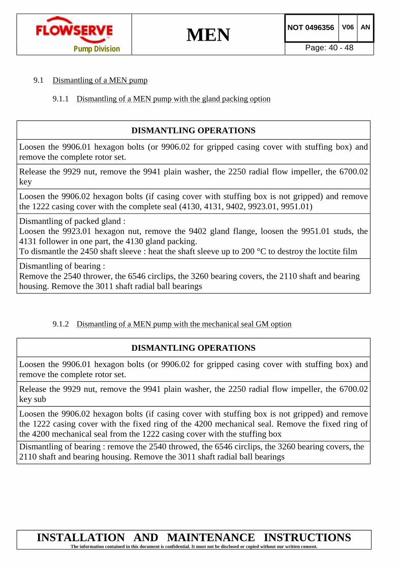
9.1 Dismantling of a MEN pump
9.1.1 Dismantling of a MEN pump with the gland packing option
DISMANTLING OPERATIONS
Loosen the 9906.01 hexagon bolts (or 9906.02 for gripped casing cover with stuffing box) andremove the complete rotor set.
Release the 9929 nut, remove the 9941 plain washer, the 2250 radial flow impeller, the 6700.02key
Loosen the 9906.02 hexagon bolts (if casing cover with stuffing box is not gripped) and removethe 1222 casing cover with the complete seal (4130, 4131, 9402, 9923.01, 9951.01)
Dismantling of packed gland :Loosen the 9923.01 hexagon nut, remove the 9402 gland flange, loosen the 9951.01 studs, the4131 follower in one part, the 4130 gland packing.To dismantle the 2450 shaft sleeve : heat the shaft sleeve up to 200 °C to destroy the loctite film
Dismantling of bearing :Remove the 2540 thrower, the 6546 circlips, the 3260 bearing covers, the 2110 shaft and bearinghousing. Remove the 3011 shaft radial ball bearings
9.1.2 Dismantling of a MEN pump with the mechanical seal GM option
DISMANTLING OPERATIONS
Loosen the 9906.01 hexagon bolts (or 9906.02 for gripped casing cover with stuffing box) andremove the complete rotor set.
Release the 9929 nut, remove the 9941 plain washer, the 2250 radial flow impeller, the 6700.02key sub
Loosen the 9906.02 hexagon bolts (if casing cover with stuffing box is not gripped) and removethe 1222 casing cover with the fixed ring of the 4200 mechanical seal. Remove the fixed ring ofthe 4200 mechanical seal from the 1222 casing cover with the stuffing boxDismantling of bearing : remove the 2540 throwed, the 6546 circlips, the 3260 bearing covers, the2110 shaft and bearing housing. Remove the 3011 shaft radial ball bearings

MEN NOT 0496356 V06 AN
Pump Division Page: 41 - 48
INSTALLATION AND MAINTENANCE INSTRUCTIONSThe information contained in this document is confidential. It must not be disclosed or copied without our written consent.
9.2 Reassembly of a MEN pump
9.2.1 Packing option
ASSEMBLY OPERATIONS
Mount the 3011 radial ball bearings with press in support on the 2110 pump shaft collars. Do not press on
the outer bearing race but on the inner one.
Press the 3260 bearing cover, pump side
Press the 6546 circlips and check its position in the bearing arrangement, pump side.
Turn over the bearing and attach the bearing cover with the circlip.
Put the bearing housing vertically, pump side, supported on the work bench, press together the shaft +radial ball bearings + 3260 bearing cover (coupling side) into the bearing housing. Position the bearings intheir arrangements without pressure, (press on the outer bearing race, if the 3260 bearing cover is notmounted).
Press the circlips on the coupling side, check its correct position in the groove
Check that the shaft freely rotates without any jarring
Verify that the axial clearance is between 0,1 and 0,5 mm.
Mount the 2540 rubber thrower against the pump cover (at 1 mm).
Carefully degrease the surface of the shaft sleeve of the 2110 shaft and the 2450 bore of the sleeve.
Spray the « T of LOCTITE » activator on the shaft sleeve surface
Lay down the 601 « LOCTITE BLOCPRESS » glue on the shaft surface and in the bore of the 2450 sleeve
Press the shaft sleeve on the shaft surface (big external bevel towards the pump) by rotating to spread wellthe glue. Wipe up the excess glue. Let the loctite glue polymerize for at least 15 min.
Prepare and clean the 1222 casing cover with stuffing box
Press the 4130 gland packing taking care to stagger the joints by 90°degrees to eachother. (See theparagraph concerning the stuffing box conception) . Press the 4131 follower.
Press the 9951.01 stuffing box studs and thoroughly tighten
Lubricate the external diameter of the 9402 gland flange
Assemble the 9402 gland flange and screw up the 9923.01 hexagon nut by hand

MEN NOT 0496356 V06 AN
Pump Division Page: 42 - 48
INSTALLATION AND MAINTENANCE INSTRUCTIONSThe information contained in this document is confidential. It must not be disclosed or copied without our written consent.
ASSEMBLY OPERATIONS
Check by hand that the shaft sleeve is secured well to the shaft
Mount the 1222 casing cover with stuffing box on the bearing, and adjust it suitably (stud of the stuffingbox in the horizontal axis).
Tighten screws of the 9906.02 casing cover with stuffing box according to torque (see torque table, do notuse striking-face wrench to block).* For the pumps 50.32.125, 65.40.125, 65.50.125, 80.65.125, 50.32.160, 65.40.160, 100.80.200 and125.100.200, the 1222 casing cover with stuffing box is gripped between the 3200 bearing and the 1111pump casing and will be fixed only when the pump casing is mounted with 9906.02 hexagon bolts.
Prepare the 2250 impeller, carefully check water lines and clean them if necessary. Lightly greasehydraulic rings.
Mount the 6700.02 key on the shaft
Mount the impeller on the shaft
Mount the 9941 plain washer
Grease the threaded shaft end. Screw up and tighten the 9929 self-braked nut while being careful withtorques (see § 9.3).
Prepare and carefully clean the 1111 pump casing.
Mount the 9621.01 and 02 hexagonal filling and drain plugs with their 4590.01 and 02 gaskets.
Put the pump casing supported on the suction flange and install the 9460 special ring.
Suspend the bearing, casing cover and impeller arrangement vertically from a lifting block and set lowerthe whole arrangement into the well orientated pump casing.
Prepare the 9906.01 or 02 hexagon bolts. For the pump of types MEN 80.65.125, 80.65.160, 80.65.200 L,100.80.160, 125.100.250 L, put a tightness product such as « TUBETANCHE 577 » on these bolts.
Screw up and stagger according to recommended torque. Do not use a striking-face wrench.
Check the mobile rotation which should not have any jarring
Mount the 6700.01 key on the shaft.
You may tighten a little, by hand, the nuts of the stuffing box.
! Reset the 9610 workpiece guards on the bearing and the 3134 support foot.

MEN NOT 0496356 V06 AN
Pump Division Page: 43 - 48
INSTALLATION AND MAINTENANCE INSTRUCTIONSThe information contained in this document is confidential. It must not be disclosed or copied without our written consent.
9.2.2 Mechanical seal option
ASSEMBLY OPERATIONS
Mount the 3011 radial ball bearings with press in support on the 2110 pump shaft collars. Do not press onthe outer bearing race but on the inner one.Press the 3260 bearing cover, pump side
Press the 6546 circlips and check its position in the bearing arrangement, pump side.
Turn over the bearing and the bearing cover rests on the circlip for a bore
Put the bearing housing vertically, pump side, supported on the work bench, press together the shaft +radial ball bearings + 3260 bearing cover (coupling side) into the bearing housing. Position the bearings intheir arrangements without pressure, (press on the outer bearing race, if the 3260 bearing cover is notmounted).
Press the circlips on the coupling side, check its correct position in the groove
Check that the shaft freely rotates without any hard spot
Check that the axial clearance is located at 0,1 mm maximum.
Prepare and clean the 1222 casing cover on the bearingTighten screws of the 9906.02 casing cover with stuffing box according to torque (see table torque, do notuse striking-face wrench to block).* For the pump 50.32.125, 65.40.125, 65.50.125, 80.65.125, 50.32.160, 65.40.160, 100.80.200 and125.100.200, the 1222 casing cover with stuffing box is gripped between the 3200 bearing and the 1111pump casing and will be fixed only when the pump casing is mounted with 9906.02 hexagon bolts.
Prepare the 4200 mechanical sealPut O-ring for rotating seal ring and joint O-ring for stationary seal ring into soapy water.Mount the stationary seal ring in the casing cover with the set of tools defined in § 9.4Mount the rotating seal ring, the spring and the mechanical seal cupel with the set of tools defined in § 9.4Prepare the 2250 impeller. Check the vanes cleanlinessGrease hydraulic ringsMount the 6700.02 key on the shaft
Mount the impeller on the shaft and avoid gripping the mechanical seal cupel.Mount the 9941 plain washer
Grease the shaft end threading. Screw up and tighten the 9929 self-braked nut and respect torques (see §9.4).
Prepare and carefully clean the 1111 pump casing.
Mount the 9621.01 and 02 hexagonal filling and drain plugs with their 4590.01 and 02 gasket.
Put the pump casing supported on the suction flange and install the 9460 special ring.
Present the bearing, the casing cover, the impeller hanging vertically from a lifting block and set the wholein the well orientated pump casing.

MEN NOT 0496356 V06 AN
Pump Division Page: 44 - 48
INSTALLATION AND MAINTENANThe information contained in this document is confidential. It must not be disclose
ASSEMBLY OPERATIONS
Prepare the 9906.01 ou 02 hexagon bolts. For the pump of types MEN 80.65.125, 80.65.160, 80.65.200 L,100.80.160, 125.100.250 L, put a tightness product such as « TUBETANCHE 577 » on these bolts.
Screw up and stagger according to recommended torque. Do not use a striking-face wrench.
Check the good rotation of the moving body (no jarring)
Mount the 6700.01 coupling key on the shaft.
! Reset the 9610 workpiece guards on the bearing and the 3134 support foot.
Nota : These recommendations correspond to a consecutive assembly and to a completedismantling. For a partial dismantling, only certain areas will be relevant.
9.3 Recommended screw torques
The torques to be applied are :
SCREW TORQUE
Casing / cover Casingcover/Bearing
HM 10 3 m.daN 3 m daNHM 12 5 m.daNHM 14 10 m.daN 5m.daN
The tightening torques have been calculated as a functiThese torques correspond to a tension of the shaft end ofThe tolerance allowed on the tightening torques is ± 30 %
9.4 Mechanical seal
The mechanical seal assembly does not need any partensured by a clear support of the mechanical seal cupelring is set with the help of the tube and the rotating sealset with the help of the assembly cone and the tube.
DiamM 1M 1M 1M 2M 2
SHAFT END NUT
eter Torque2 6 m daN4 8 m daN8 12 m.daN0 14 m.daN4 16 m.daN
CE INSTRUCTIONSd or copied without our written consent.
on of the forces produced by the pumps. 25 % to 50 % of the elastic limit.
icular adjustment. The correct setting is on the impeller hub. The stationary seal ring, with its joint slided on the shaft, is

MEN NOT 0496356 V06 AN
Pump Division Page: 45 - 48
INSTALLATION AND MAINTENANCE INSTRUCTIONSThe information contained in this document is confidential. It must not be disclosed or copied without our written consent.
Set of tools for mechanical seal assembly (not supplied by FLOWSERVE)
Tube for stationary Assembly cone Tube to completeseal ring for rotating seal ring setting of the ring
O-ring φ3
SET OF TOOLS SET OF TOOLS DIMENSIONS PUMP TYPEφA+0,5
0 φB±0,1 φC±0,2 φD±0,2 φE±0,15
0φG±0,1 φF±0,2 L MEN
TUBE FOR 42 39,7 30 28,5 3,3 1,25 3 60
50-32-125,50-32-160,50-32-20050-32-200L,65-40-125,65-40-16065-40-200L,65-40-250,65-40-250L65-50-125,65-50-160,65-50-200L65-50-250L,80-65-125,80-65-16080-65-200L,100-80-160
STATIONARY
SEAL RING55 52,7 44,1 38,5 3,3 1,25 3 60
80-65-250L,80-65-315,100-80-200L100-80-250L,100-80-315,125-100-200L125-100-250L,125-100-315,125-100-315L150-125-250L
69 66,9 54,4 51 3,3 1,25 5,5 60 125-100-400,125-100-400L,150-125-315L150-125-400L,200-150-315L,200-150-400L
φA±0,1 φB+0,1
0 φDg6 L±0,5MEN
ASSEMBLY22 19 16 30
50-32-125,50-32-160,50-32-20065-40-125,65-40-160,65-50-12565-50-160,80-65-125
CONE FOR 28 24 20 4050-32-200L,65-40-200L,65-40-25065-40-250L,65-50-200L,65-50-12580-65-160,80-65-200L,100-80-160
ROTATING 38 28 24 55 80-65-315,100-80-315,125-100-315
SEAL RING 38 34 32 6080-65-250L,100-80-200L,100-80-250L125-100-200L,125-100-250L125-100-315L,150-125-250L
50 46 40 69 125-100-400,125-100-400L150-125-315L150-125-400L,200-150-315L,200-150-400L
φA±0,2 φB+0,4
0 φD±0,1 φH+0,1 L MEN
TUBE FOR
ROTATING37 28,5 28,5 7,9 60
50-32-125,50-32-160,50-32-20050-32-200L,65-40-125,65-40-16065-40-200L,65-40-250,65-40-250L65-50-125,65-50-160,65-50-200L65-50-250L,-80-65-125,80-65-16080-65200L,100-80-160
SEAL RING46,1 38,5 38,5 7,9 60
80-65-250L,80-65-315,100-80-200L100-80-250L,100-80-315,125-100-200L125-100-250L,125-100-315125-100-315L,150-125-250L
60,5 51 51 8,5 60125-100-400,125-100-400L150-125-315L,150-125-400L200-150-315L,200-150-400L

MEN NOT 0496356 V06 AN
Pump Division Page: 46 - 48
INSTALLATION AND MAINTENANCE INSTRUCTIONSThe information contained in this document is confidential. It must not be disclosed or copied without our written consent.
10. RECOMMENDED SPARES
Flowserve keep records of all pumps that have been supplied. When ordering spares the followinginformation should be quoted.
(1) Pump serial number(2) Pump size(3) Part name(4) Part number(5) Number of parts required
The pump size and serial number are shown on the pump nameplate.
To ensure continued satisfactory operation, replacement parts to the original design specificationshould be obtained from Flowserve. Any change to the original design specification (modification oruse of a non-standard part) will invalidate the pumps safety certification.
Apply the request to : FLOWSERVE POMPESRoute d'Angers72234 Arnage CedexFRANCE
Tél : 02 43 40 57 34 (33) 2 43 40 57 34Télex : 720079Fax : 02 43 40 58 17 (33) 2 43 40 58 17
10.1 Recommended Spares
1500, 2250, 3011, 4130 (ou 4200), 4590-01, 4590-02, 9460
Destroy all the rings after dismantling, replace them when reassembling
IT IS RECOMMENDED THAT BEARINGS ARE NOT REUSED AFTER ANYREMOVAL FROM THE SHAFT.
After serving during two years, replace the gland packing.

MEN NOT 0496356 V06 AN
Pump Division Page: 47 - 48
INSTALLATION AND MAINTENANCE INSTRUCTIONSThe information contained in this document is confidential. It must not be disclosed or copied without our written consent.
10.2 General arrangement drawing
MEN pumps
IMPELLER DIAMETER 125 Without back hub ring Clamped casing cover With wear-rings (MEN pumps)

MEN NOT 0496356 V06 AN
Pump Division Page: 48 - 48
INSTALLATION AND MAINTENANCE INSTRUCTIONSThe information contained in this document is confidential. It must not be disclosed or copied without our written consent.
10.3 Sectional drawing parts list
ITEMS DESIGNATION
1111 Pump casing1222 Casing cover with stuffing box1500 Wear ring2110 Pump shaft2250 Radial flow impeller2450 Shaft sleeve2540 Thrower3011 Radial ball bearings3134 Support foot3200 Bearing housing3260 Bearing cover4130 Gland packing4131 Follower4200 Mechanical seal
4590-01 Gasket4590-02 Gasket
6546 Circlip6700-01 Key6700-02 Key
9402 Gland flange9460 Special ring9610 Various protections
9621-01 Screwed plug9621-02 Screwed plug
9683 Description plate9906-01 Hexagon bolt9906-02 Hexagon bolt9906-03 Hexagon bolt9923-01 Hexagon nut9923-02 Hexagon nut
9929 Self-braked nut9941 Plain washer
9951-01 Stud