Embed Size (px)
Citation preview

LLNL-TR-407386 – Rev. 1
LIFE Materials: Overview of Fuels and Structural
Materials Issues Volume 1
October 25, 2008
Author: J.C. Farmer This work performed under the auspices of the U.S. Department of Energy by Lawrence Livermore National Laboratory under Contract DE-AC52-07NA27344.

1
LIFE Materials:
Overview of Fuels and Structural Materials Issues
Volume 1
Joseph Collin Farmer
Chemistry, Materials, Earth and Life Sciences Directorate
National Ignition Facility and Photon Sciences Directorate
Lawrence Livermore National Laboratory
7000 East Avenue
Livermore, California 94550
July 4th 2008 – First Draft Completed
September 6th 2008 – Revision 0a
September 29th 2008 – Revision 0b
October 25th 2008 – Revision 1a

2
Executive Summary The National Ignition Facility (NIF) project, a laser-based Inertial Confinement Fusion (ICF) experiment designed to achieve thermonuclear fusion ignition and burn in the laboratory, is under construction at the Lawrence Livermore National Laboratory (LLNL) and will be completed in April of 2009. Experiments designed to accomplish the NIF’s goal will commence in late FY2010 utilizing laser energies of 1 to 1.3 MJ. Fusion yields of the order of 10 to 20 MJ are expected soon thereafter.
Laser initiated fusion-fission (LIFE) engines have now been designed to produce nuclear power from natural or depleted uranium without isotopic enrichment, and from spent nuclear fuel from light water reactors without chemical separation into weapons-attractive actinide streams. A point-source of high-energy neutrons produced by laser-generated, thermonuclear fusion within a target is used to achieve ultra-deep burn-up of the fertile or fissile fuel in a sub-critical fission blanket. Fertile fuels including depleted uranium (DU), natural uranium (NatU), spent nuclear fuel (SNF), and thorium (Th) can be used. Fissile fuels such as low-enrichment uranium (LEU), excess weapons plutonium (WG-Pu), and excess highly-enriched uranium (HEU) may be used as well. Based upon preliminary analyses, it is believed that LIFE could help meet worldwide electricity needs in a safe and sustainable manner, while drastically shrinking the nation’s and world’s stockpile of spent nuclear fuel and excess weapons materials. LIFE takes advantage of the significant advances in laser-based inertial confinement fusion that are taking place at the NIF at LLNL where it is expected that thermonuclear ignition will be achieved in the 2010-2011 timeframe.
Starting from as little as 300 to 500 MW of fusion power, a single LIFE engine will be able to generate 2000 to 3000 MWt in steady state for periods of years to decades, depending on the nuclear fuel and engine configuration. Because the fission blanket in a fusion-fission hybrid system is subcritical, a LIFE engine can burn any fertile or fissile nuclear material, including un-enriched natural or depleted U and SNF, and can extract a very high percentage of the energy content of its fuel resulting in greatly enhanced energy generation per metric ton of nuclear fuel, as well as nuclear waste forms with vastly reduced concentrations of long-lived actinides. LIFE engines could thus provide the ability to generate vast amounts of electricity while greatly reducing the actinide content of any existing or future nuclear waste and extending the availability of low cost nuclear fuels for several thousand years. LIFE also provides an attractive pathway for burning excess weapons Pu to over 99% FIMA (fission of initial metal atoms) without the need for fabricating or reprocessing mixed oxide fuels (MOX). Because of all of these advantages, LIFE engines offer a pathway toward sustainable and safe nuclear power that significantly mitigates nuclear proliferation concerns and minimizes nuclear waste.

3
An important aspect of a LIFE engine is the fact that there is no need to extract the fission fuel from the fission blanket before it is burned to the desired final level. Except for fuel inspection and maintenance process times, the nuclear fuel is always within the core of the reactor and no weapons-attractive materials are available outside at any point in time. However, an important consideration when discussing proliferation concerns associated with any nuclear fuel cycle is the ease with which reactor fuel can be converted to weapons usable materials, not just when it is extracted as waste, but at any point in the fuel cycle. Although the nuclear fuel remains in the core of the engine until ultra deep actinide burn up is achieved, soon after start up of the engine, once the system breeds up to full power, several tons of fissile material is present in the fission blanket. However, this fissile material is widely dispersed in millions of fuel pebbles, which can be tagged as individual accountable items, and thus made difficult to divert in large quantities.
Several topical reports are being prepared on the materials and processes required for the LIFE engine. Specific materials of interest include:
• Baseline TRISO Fuel (TRISO)
• Inert Matrix Fuel (IMF) & Other Alternative Solid Fuels
• Beryllium (Be) & Molten Lead Blankets (Pb/PbLi)
• Molten Salt Coolants (FLIBE/FLiNaBe/FLiNaK)
• Molten Salt Fuels (UF4 + FLIBE/FLiNaBe)
• Cladding Materials for Fuel & Beryllium
• ODS FM Steel (ODS)
• Solid First Wall (SFW)
• Solid-State Tritium Storage (Hydrides)
This Topical Report is Volume 1 in a 12-volume series which is summarized below, and discusses data and models pertinent to the performance of materials in LIFE engine applications found in Volumes 2 through 9. It also discusses current understanding of issues related to proliferation resistance, repository requirements, and licensibility found in Volumes 10, 11 and 12, respectively. Liquid metal coolants such as Pb-17Li may have to be dealt with in future editions as the engine design further evolves.
4
Topical reports are organized in 12 volumes:
• Volume 1 – Overview of Fuels & Structural Materials Issues
• Volume 2 – Design & Fabricability
• Volume 3 – Transmutation & Phase Formation
• Volume 4 – Radiation Effects
• Volume 5 – Thermomechanical Effects
• Volume 6 – Corrosion & Environmental Cracking
• Volume 7 – Molten-Salt Coolants
• Volume 8 – Molten-Salt Fuels
• Volume 9 – On-Site Solid-State Tritium Storage
• Volume 10 – Proliferation Resistance
• Volume 11 – Fuel Cycle & Repository
• Volume 12 – Licensability
Volume 1, entitled Overview of Fuels and Structural Materials Issues, is organized as follows:
• Executive Summary
• Table of Contents, List of Tables, and List of Figures
• Acronyms & Nomenclature
• Chapter A. LIFE Requirements for Materials
• Chapter B. Summarize Existing Knowledge
• Chapter C. Gaps in Knowledge & System Vulnerabilities
• Chapter D. Strategy for Future Work
• Bibliography
• Tables Summarizing Important Properties
• Figures & Illustrations

5
Table of Contents Executive Summary ........................................................................................................................ 2
Table of Contents............................................................................................................................ 5
List of Tables .................................................................................................................................. 9
List of Figures ............................................................................................................................... 10
Acronyms...................................................................................................................................... 16
Chapter A. LIFE Requirements for Materials............................................................................... 18
Mission...................................................................................................................................... 18
Materials of Construction ......................................................................................................... 18
Tungsten First Wall................................................................................................................... 19
Neutron Multiplication Blanket ................................................................................................ 19
Fission Blanket.......................................................................................................................... 20
Structural Materials................................................................................................................... 20
Molten Salt Coolant .................................................................................................................. 21
Chapter B. Summary of Existing Knowledge............................................................................... 22
Topical Report .......................................................................................................................... 22
Nuclear Reactions ..................................................................................................................... 22
Tungsten First Wall................................................................................................................... 23
Neutron Multiplication Blanket ................................................................................................ 24
Sub-Critical Fission Blanket ..................................................................................................... 25
Fertile & Fissile Material Options ........................................................................................ 25
Baseline TRISO Fuel for LIFE Engine................................................................................. 26
Solid Hollow Core Fuel ........................................................................................................ 29
Fuel Fabrication Processes.................................................................................................... 29
Coolants and Liquid Fuels ........................................................................................................ 29

6
Coolants ................................................................................................................................ 29
Liquid Fuels & Continuous On-Line Reprocessing.............................................................. 31
Tritium Recovery & Permeation........................................................................................... 32
Selection of Structural and First Wall Materials....................................................................... 33
Iron-Based and Nickel-Based Steels..................................................................................... 34
Oxide Dispersion Strengthened Ferritic-Martensitic Steels ................................................. 35
Alternatives to Steel.............................................................................................................. 36
Vanadium Alloys .................................................................................................................. 36
Molybdenum Alloys ............................................................................................................. 37
Niobium Alloys..................................................................................................................... 37
Other Advanced Materials of Interest................................................................................... 38
Radiation Damage of Engine Materials.................................................................................... 39
Effect for Radiation on Structural Steels, Refractory Alloys and Ceramics......................... 39
Effect for Radiation on Oxide Dispersion Strengthened (ODS) Ferritic Steels ................... 39
Effect of Radiation on Nickel-Based Alloys ........................................................................ 40
Effect of Radiation on Beryllium Neutron Multiplier .......................................................... 41
Corrosive Attack of Engine Materials ...................................................................................... 41
Corrosion Mechanisms ......................................................................................................... 41
Corrosion Models.................................................................................................................. 44
Application of Mixed Potential Theory to Engine Materials................................................ 45
Cathodic Protection and Sacrificial Anodes ......................................................................... 47
Corrosion Rate Limited by Corrosion Product Solubility .................................................... 49
Mechanical Fracture and Fatigue.......................................................................................... 50
Environmental Fracture ........................................................................................................ 50
End of Fuel Cycle ..................................................................................................................... 51

7
Limited Production of Weapons-Attractive Materials.......................................................... 53
Interim Storage...................................................................................................................... 53
Geological Disposal of Spent LIFE Fuels ............................................................................ 55
Other Alternatives................................................................................................................. 58
Safe Handling of Tritium...................................................................................................... 58
Cost and Availability of Advanced Materials........................................................................... 58
Cost of Advanced Steels ....................................................................................................... 58
Requirements of Lithium & Beryllium for LIFE Reactor .................................................... 59
Availability of Beryllium...................................................................................................... 59
Availability of Lithium ......................................................................................................... 60
Summary ................................................................................................................................... 62
Chapter C. Gaps in Knowledge & System Vulnerabilities........................................................... 63
Chapter D. Strategy for Future Work ........................................................................................... 64
Fuel Development..................................................................................................................... 65
Objectives – Fuels................................................................................................................. 65
Tasks – Fuels......................................................................................................................... 66
Deliverables – Fuels.............................................................................................................. 67
Structural and First Wall Materials........................................................................................... 68
Objectives ............................................................................................................................. 68
Tasks – Structural & First Wall Materials ............................................................................ 69
Deliverables – Structural & First Wall Materials ................................................................. 70
Summary ....................................................................................................................................... 71
Acknowledgements....................................................................................................................... 71
Financial Support ...................................................................................................................... 71
Visionary Leadership ................................................................................................................ 71

8
Bibliography ................................................................................................................................. 72
Tables............................................................................................................................................ 79
Figures......................................................................................................................................... 104
Appendix A................................................................................................................................. 166
Other High-Temperature Materials as Building Blocks ......................................................... 166
Carbides .............................................................................................................................. 166
Nitrides................................................................................................................................ 166
Borides ................................................................................................................................ 166
Intermetallics....................................................................................................................... 166
Silicides............................................................................................................................... 167
Carbon................................................................................................................................. 167
Tungsten.............................................................................................................................. 167
Tantalum ............................................................................................................................. 168
Molybdenum....................................................................................................................... 168
Molybdenum Alloys ........................................................................................................... 168
Niobium .............................................................................................................................. 168
Niobium Alloys................................................................................................................... 169
Vanadium............................................................................................................................ 169
Vanadium Alloys ................................................................................................................ 169
Chromium ........................................................................................................................... 169
Platinum .............................................................................................................................. 170
Titanium.............................................................................................................................. 170

9
List of Tables Table 1 – Performance Characteristics of Various Types of LIFE Plants.................................... 79
Table 2 – Fluence and Damage Levels in the LIFE Engine ......................................................... 80
Table 3 – Density and Melting Points of Candidate Fissionable Fuels ........................................ 80
Table 4 – Challenges Facing TRISO Fuels & Mitigation Strategies............................................ 81
Table 5 – Blanket and Coolant Properties .................................................................................... 82
Table 6 – Important Physical Properties of Candidate Structural Materials ................................ 84
Table 7 – Nuclear Related Properties of Candidate Structural Materials..................................... 86
Table 8 – Radiation Swelling of Inconel 600 ............................................................................... 87
Table 9 – Guidance on Acceptable Compositions for Oxidation-Resistant Refractory Steels..... 88
Table 10 – Materials Compatibility with Li2BeF4 Coolant .......................................................... 89
Table 11– Free Energies of Formation for Various Fluorides...................................................... 90
Table 12 – Corrosion of Steels in High Temperature Molten Salts.............................................. 91
Table 13 – Solubilities of Chromium in Various Fluoride Salts .................................................. 94
Table 14 – Worldwide LWR SNF Inventories & Required YME Repositories........................... 95
Table 15 – Equivalent Worldwide LIFE SNF Inventories & Required YME Repositories......... 96
Table 16 – Comparison of LWR & Equivalent LIFE Fleets: Required YME Repositories......... 97
Table 17 – Comparison of Mass Flow & TRU Generation for Various Fuel Cycles................... 98
Table 18 – Assumed System Properties for Interim Storage...................................................... 100
Table 19 – Interim Storage Assuming Area Fraction Available for Heat Conduction = 0.10 ... 101
Table 20 – Interim Storage Assuming Area Fraction Available for Heat Conduction = 0.05 ... 102
Table 21 – Key radionuclides in TSPA for Yucca Mountain..................................................... 103
10
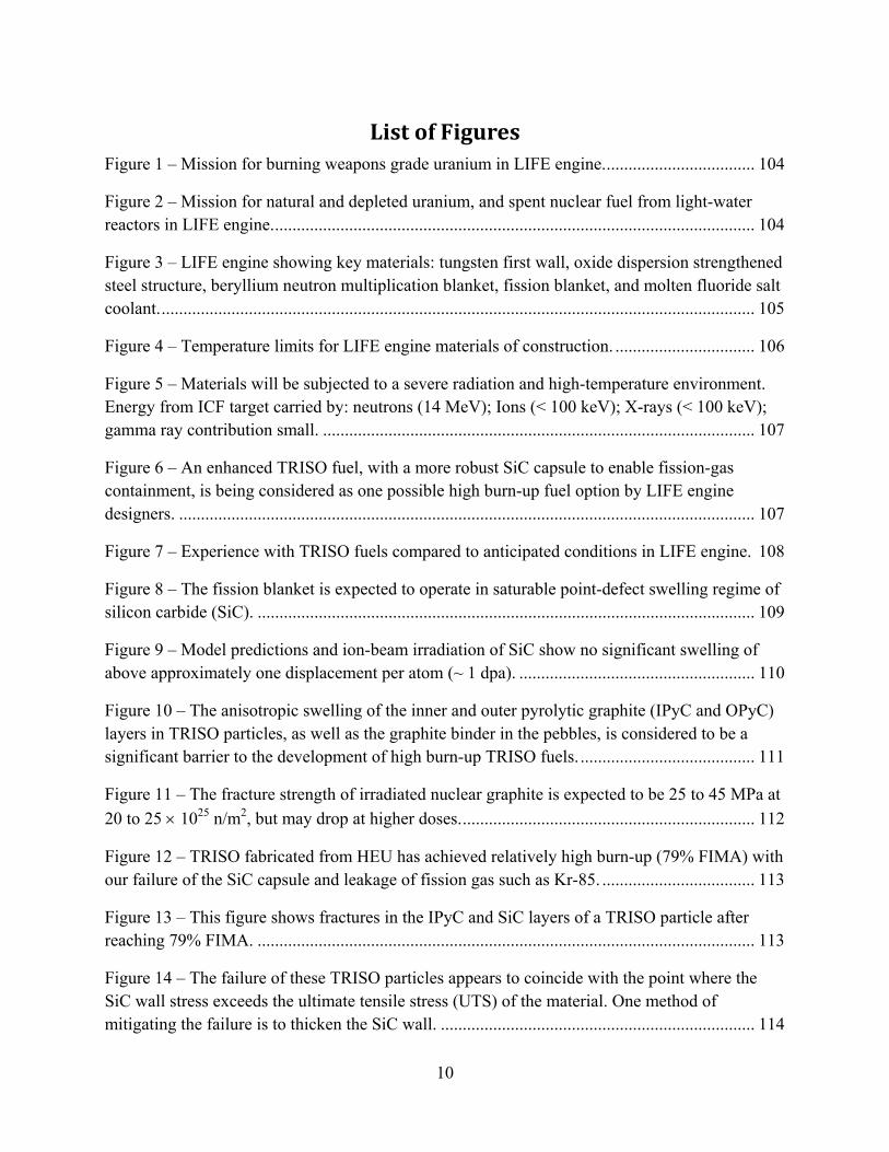
List of Figures Figure 1 – Mission for burning weapons grade uranium in LIFE engine................................... 104
Figure 2 – Mission for natural and depleted uranium, and spent nuclear fuel from light-water reactors in LIFE engine............................................................................................................... 104
Figure 3 – LIFE engine showing key materials: tungsten first wall, oxide dispersion strengthened steel structure, beryllium neutron multiplication blanket, fission blanket, and molten fluoride salt coolant......................................................................................................................................... 105
Figure 4 – Temperature limits for LIFE engine materials of construction. ................................ 106
Figure 5 – Materials will be subjected to a severe radiation and high-temperature environment. Energy from ICF target carried by: neutrons (14 MeV); Ions (< 100 keV); X-rays (< 100 keV); gamma ray contribution small. ................................................................................................... 107
Figure 6 – An enhanced TRISO fuel, with a more robust SiC capsule to enable fission-gas containment, is being considered as one possible high burn-up fuel option by LIFE engine designers. .................................................................................................................................... 107
Figure 7 – Experience with TRISO fuels compared to anticipated conditions in LIFE engine. 108
Figure 8 – The fission blanket is expected to operate in saturable point-defect swelling regime of silicon carbide (SiC). .................................................................................................................. 109
Figure 9 – Model predictions and ion-beam irradiation of SiC show no significant swelling of above approximately one displacement per atom (~ 1 dpa). ...................................................... 110
Figure 10 – The anisotropic swelling of the inner and outer pyrolytic graphite (IPyC and OPyC) layers in TRISO particles, as well as the graphite binder in the pebbles, is considered to be a significant barrier to the development of high burn-up TRISO fuels. ........................................ 111
Figure 11 – The fracture strength of irradiated nuclear graphite is expected to be 25 to 45 MPa at 20 to 25 × 1025 n/m2, but may drop at higher doses.................................................................... 112
Figure 12 – TRISO fabricated from HEU has achieved relatively high burn-up (79% FIMA) with our failure of the SiC capsule and leakage of fission gas such as Kr-85. ................................... 113
Figure 13 – This figure shows fractures in the IPyC and SiC layers of a TRISO particle after reaching 79% FIMA. .................................................................................................................. 113
Figure 14 – The failure of these TRISO particles appears to coincide with the point where the SiC wall stress exceeds the ultimate tensile stress (UTS) of the material. One method of mitigating the failure is to thicken the SiC wall. ........................................................................ 114

11
Figure 15 – SiC wall stress verses fuel burn-up for enhanced TRISO fuel for LIFE engine. .... 115
Figure 16 – Crack initiation at defects in silicon carbide layer are being accounted for in finite element model, and the calculations based upon that model. ..................................................... 116
Figure 17 – TRISO will experience dynamic stress due to thermal pulsing at 10 ot 20 Hz, which may cause thermal fatigue. ......................................................................................................... 116
Figure 18 – Phase diagram showing formation of low-melting Pd5Si as a result of the reaction of a Pd (fission product) with SiC capsule in TRISO fuel particle. ................................................ 117
Figure 19 – Phase transformations in fission fuels at high burn-up are being modeled. Relevant binaries include: C-Pu, O-Pu, O-U, Pu-U, Pd-Si, Pd-C, Si-C & others. .................................... 118
Figure 20 – Solid-hollow core (SHC) fuel design with high uranium mass fraction and enhanced strength encapsulation materials. ................................................................................................ 119
Figure 21 – Predicted stress in the wall of solid hollow-core (SHC) fuel at fission gas pressures corresponding to 20, 40, 60, 80 and 99.9% FIMA. .................................................................... 120
Figure 22 – Numerical analysis indicates a substantial strength margin in SHC pressure boundary. In all cases, the stress is well below the yield and ultimate tensile stresses of the wall material. ...................................................................................................................................... 120
Figure 23 – Enhanced TRISO Process for Nat-U & DU. ........................................................... 121
Figure 24 – Other processes may be needed for the conversion of light water reactor spent nuclear fuel into LIFE fuel.......................................................................................................... 121
Figure 25 – A binary mixture of BeF2 and LiF to form Li2BeF4 produces a eutectic composition with a low melting point of less than 400°C............................................................................... 122
Figure 26 – Phase diagram reveals regions of stable operation for liquid fuels in LIFE engine.123
Figure 27 – New ODS FM steels such as 9Cr-ODS & Kobe 12YWT have demonstrated exceptional tensile strength at high temperature......................................................................... 124
Figure 28 – New ODS FM steels such as 9Cr-ODS & Kobe 12YWT have demonstrated exceptional creep resistance at high temperature; additional development is needed................ 125
Figure 29 – Additional data for EUROFER 97 showing the exceptional high-temperature strength and creep resistance of ODS steels. .............................................................................. 126
Figure 30 – Fatigue cycling of 9Cr-Fe and 12Cr-Fe ODS at temperatures from 600 to 800°C. 127

12
Figure 31 – Ferritric steels experience less irradiation-induced swelling than Type 316 austenitic stainless steel............................................................................................................................... 128
Figure 32 – Ion-beam irradiation of 9Cr-Fe ODS ferritic steel has shown no detectable void formation up to 150 displacements per atom.............................................................................. 129
Figure 33 – Ion-beam irradiation of ODS steel has shown no detectable void formation up to 150 displacements per atom............................................................................................................... 130
Figure 34 – Dispersions in matrix mitigate irradiation-induced swelling attributable to helium...................................................................................................................................................... 131
Figure 35 – ODS FM steels have been successfully joined using industrial welding processes.132
Figure 36 – Fuel pins with ODS steel cladding and welded end-caps........................................ 133
Figure 37 – The microstructure of 9-12% Cr steels can be improved dramatically with hot rolling, which is known in the literature as thermomechanical treatment (TMT). ..................... 134
Figure 38 – Mechanism for corrosion of ODS ferritic steel, showing formation of the chromium depletion layer, and dissolution of iron and chromium into the molten salt............................... 135
Figure 39 – Mixed potential theory applied to ODS ferritic steel without sacrificial beryllium anode in molten Li2BeF4 at 815°C.............................................................................................. 136
Figure 40 – Mixed potential theory applied to ODS ferritic steel with sacrificial beryllium anode in molten Li2BeF4 at 815°C. ....................................................................................................... 136
Figure 41 – A comparison of these two curves, taken from Figures 39 and 40 respectively, clearly show the cathodic shift of the open circuit corrosion potential due to galvanic coupling of beryllium and ODS steel at 815°C.............................................................................................. 137
Figure 42 – Limited corrosive attack of ODS by molten salts, assuming a rate of attack of 5.0 mils per year, and saturation of the salt with chromium at a concentration of approximately 3,000 parts per million. ......................................................................................................................... 138
Figure 43 – Limited corrosive attack of ODS by molten salts, assuming a rate of attack of 70.1 mils per year, and saturation of the salt with chromium at a concentration of approximately 3000 parts per million. ......................................................................................................................... 139
Figure 44 – LIFE engine’s fuel-cycle story, including interim storage and disposal of waste in geological repository................................................................................................................... 140
Figure 45 – TRU inventory in fission blanket of LIFE engine (spent fuel) at various levels of burn-up (FIMA). ......................................................................................................................... 141
13
Figure 46 – Compositon of fission blanket of LIFE engine (spent fuel) at various levels of burn-up (FIMA)................................................................................................................................... 142
Figure 47 – Assuming current statutory limits for the disposal of spent nuclear fuel, a single Yucca Mountain repository could service more LIFE engines that light-water reactors. .......... 143
Figure 48 – A single Yucca Mountain repository could enable more electrical power generation with a fleet of LIFE engines than with a fleet of light-water reactors. ....................................... 143
Figure 49 – Electrical generating capacity for 1st Scenario: LWR fleet with no LIFE and energy deficit. ......................................................................................................................................... 144
Figure 50 – Electrical generating capacity for 2nd scenario: LIFE introduced in 2030 to fill the projected need for electrical power............................................................................................. 145
Figure 51 – SNF generated for two scenarios: (1) light water reactors with no LIFE engines and (2) introduction of LIFE engines in 2030. .................................................................................. 146
Figure 52 – Repositories required for two scenarios: (1) LWR with no LIFE and (2) LIFE intro in 2030. ....................................................................................................................................... 147
Figure 53 – LIFE engine’s more complete burn generates far less plutonium per reactor than typical LWR................................................................................................................................ 148
Figure 54 – LIFE engine’s more complete burn also generates less TRU per reactor than LWR...................................................................................................................................................... 148
Figure 55 – LIFE fuel pebble is less attractive target than LWR fuel rod since the pebble has less TRU and more radioactivity. ...................................................................................................... 149
Figure 56 – LIFE fuel (pebble) is a much less attractive target for theft than LWR fuel (rod): less TRU and more radioactivity. ...................................................................................................... 149
Figure 57 – Power Curves for interim storage of LIFE spent fuel in standard transportation, aging and disposal container during dry interim storage with area fraction for heat transfer between TRISO pebbles of 0.10. .............................................................................................................. 150
Figure 58 – Temperature and cooling air required for LIFE spent fuel in standard transportation, aging, and disposal container during dry interim storage with area fraction for heat transfer between TRISO pebbles of 0.10. ................................................................................................ 151
Figure 59 – Artist’s rendering of drift inside of Yucca Mountain Repository with temperature limits shown. ............................................................................................................................... 152
Figure 60 – A comparison of the heat generated by containers filled with LIFE and LWR spent nuclear fuels during the first million years. ................................................................................ 153

14
Figure 61 – Temperature of the container filled with LIFE spent fuel (waste package), drift wall, and ventilation air used for cooling during the pre-closure sequential emplacement of finge containers (from single LIFE engine) in a repository drift, assuming no preceding period of interim storage for cooling.......................................................................................................... 154
Figure 62 – A comparison of the radioactivity from containers filled with LIFE and LWR spent nuclear fuels during the first million years. ................................................................................ 155
Figure 63 – Comparison of energy-normalized inventories of radionuclides considered to be significant for the performance of the Yucca Mountain repository............................................ 156
Figure 64 – Comparison of mass-normalized inventories of radionuclides considered to be significant for the performance of the Yucca Mountain repository............................................ 157
Figure 65 – The risk-to-benefit ratio for a Yucca Mountain repository completely filled with spent nuclear fuel from a fleet of LIFE engines compared to that of a similar repository completely filled with spent fuel from a fleet of light water reactors, showing risk for the LIFE scenario. ...................................................................................................................................... 158
Figure 66 – Simple scaling suggests that the risk of a Yucca Mountain repository completely filled with spent nuclear fuel from LIFE engines is slightly more than that of a repository completely filled with spent nuclear fuel from a fleet of light-water reactors, but still well within the statutory limits established with 10 CFR 63. ........................................................................ 159
Figure 67 – A side-by-side comparison of two proposed fuel cycles, one for the accelerator transmutation of waste and another with LIFE engines.............................................................. 160
Figure 68 – LIFE requires safe on-site tritiuim storage with solid-state tritide systems, which have been demonstrated on relatively large scale....................................................................... 161
Figure 69 – Equilibrium pressure as a function of temperature for numerous solid-state storage media for hydrogen isotopes including tritium........................................................................... 161
Figure 70 – Cost of raw materials required for the production of ferritic and austenitic steels, nickel-based alloys, and various refractory alloys. These costs were provided by the United States Geological Survey (USGS). ............................................................................................. 162
Figure 71 – The proven U.S. reserves, U.S. mine shipments, and world mine shipments of beryllium expressed in metric tons. ............................................................................................ 163
Figure 72 – The number of LIFE engines that can be built from proven US reserves, US mine shipments, and world mine shipments of beryllium. .................................................................. 163
Figure 73 – The proven U.S. reserves, U.S. consumption and exports, deducting imports, and world production of lithium, expressed in metric tons. .............................................................. 164

15
Figure 74 – The number of LIFE engines that can be built from proven U.S. reserves, U.S. consumption and exports, deducting imports, and world production of lithium. ....................... 164
Figure 75 – A systematic approach to materials modeling will enable design of next-generation materials...................................................................................................................................... 165
Figure 76 – Accelerated testing of materials will be done in three-beam accelerator. ............... 165

16
Acronyms ATR Advanced Test Reactor
ABWR Advanced Boiling Water Reactor
ALWR Advanced Light Water Reactor
APWR Advanced Pressurized Water Reactor
BHN Brinell Hardness Number
BWR Boiling Water Reactor
CTE Coefficient of Thermal Expansion
CV Cyclic Voltammetry
EIS Electrochemical Impedance Spectroscopy
FFHR Force Free Helical Reactor
FIMA Fission of Initial Metal Atoms
FLIBE: Molten Fluoride Salt (Li2BeF4)
FLINABE Molten Fluoride Salt (LiNaBeF4)
FLINAK Molten Fluoride Salt (Li-Na-K-F)
HEU Highly Enriched Uranium
HIC Hydrogen Induced Cracking
HFIR High Flux Isotope Reactor
ICF Inertial Confinement Fusion
INL Idaho National Laboratory
IMF Inert Matrix Fuel
IPyC Inner Pyrolytic Carbon (Layer)
LEU Low Enriched Uranium
LIFE Laser Initiated Fusion-Fission Energy
LLNL Lawrence Livermore National Laboratory

17
LP Linear Polarization
LWR Light Water Reactor
MD Molecular Dynamic
NIC National Ignition Campaign
NIF National Ignition Facility
NP New Production
NPR New Production Reactor
MHTGR Modular High Temperature Gas-Cooled Reactor
OCP Open Circuit Potential
ODS Oxide Dispersion Strengthened
OPyC Outer Pyrolytic Carbon (Layer)
ORNL Oak Ridge National Laboratory
PWR Pressurized Water Reactor
RN Radionuclide
SCC Stress Corrosion Cracking
SDR Slip Dissolution Repassivation
SHC Solid Hollow Core Fuel
SNF Spent Nuclear Fuel
SSRT Slow Strain Rate Testing
TMT Thermo Mechanical Treatment
TRISO TRI-ISO-tropic Fuel
UTS Ultimate Tensile Strength
WP Waste Package
YMP Yucca Mountain Project

18
Chapter A. LIFE Requirements for Materials
Mission There are three primary missions for the LIFE engine, which include the burning of excess weapons-grade plutonium (WG-Pu), natural and depleted uranium (DU and HEU), and light-water reactor (LWR) spent nuclear fuel (SNF). The LIFE engine enable the direct burning of such fuels with no isotopic enrichment or chemical separation, with the potential to attain very high burn-up, which is quantified in terms of fission of initial metal atoms (FIMA).
Weapons grade plutonium (WG-Pu) and highly-enriched uranium (HEU) can be digested directly into a molten salt, thereby forming a high burn-up liquid fuel for the direct incineration of old weapons materials, as shown in Figure 1. Natural and depleted uranium (Nat-U and DU) can be incorporated into a variety of solid fuels including TRI-structural ISO-tropic fuel (TRISO), baseball or solid hollow core (SHC), inert matrix fuel (IMF), and encapsulated powder fuels, as shown in Figure 2.
The performance characteristics of various types of LIFE engines, capable of burning both depleted uranium and plutonium, are summarized Table 1. Plants based upon “hot-spot” ignition require only a compression laser, while plants based on “fast ignition” require both compression and ignition lasers.
Materials of Construction The fusion-fission chamber is the heart of the LIFE engine, and is shown in Figure 3. Materials of construction fall into several broad categories, including: (1) lasers and optics, (2) fusion targets, (3) tungsten first wall, (4) neutron multiplication blanket, (5) sub-critical fission blanket, (6) structural and cladding materials, (7) coolants and/or liquid fuels, (8) reflector, and (9) balance of plant. Issues related to lasers and optics, as well as fusion targets are discussed elsewhere. This collection of topical reports focuses on fission fuels, structural and first wall materials, the neutron multiplier, coolants and some special materials such as metal tritides required for the balance of plant. This report focuses on the interaction of (6) structural and cladding materials with (7) coolants and/or liquid fuels. As shown in Figure 4, the operating windows for these materials are bounded by radiation embrittlement at lower temperatures, and by thermal creep at higher temperatures. The operating conditions for LIFE have been selected to enable the survivability of known materials of construction.
19
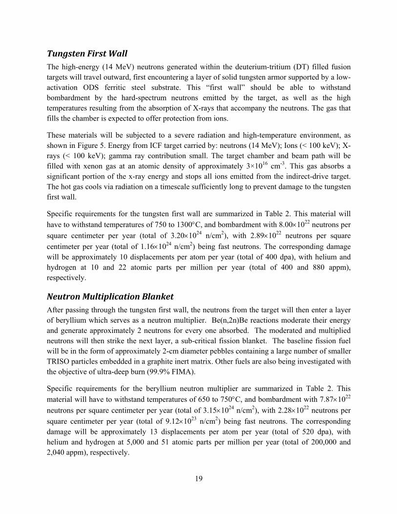
Tungsten First Wall The high-energy (14 MeV) neutrons generated within the deuterium-tritium (DT) filled fusion targets will travel outward, first encountering a layer of solid tungsten armor supported by a low-activation ODS ferritic steel substrate. This “first wall” should be able to withstand bombardment by the hard-spectrum neutrons emitted by the target, as well as the high temperatures resulting from the absorption of X-rays that accompany the neutrons. The gas that fills the chamber is expected to offer protection from ions.
These materials will be subjected to a severe radiation and high-temperature environment, as shown in Figure 5. Energy from ICF target carried by: neutrons (14 MeV); Ions (< 100 keV); X-rays (< 100 keV); gamma ray contribution small. The target chamber and beam path will be filled with xenon gas at an atomic density of approximately 3×1016 cm-3. This gas absorbs a significant portion of the x-ray energy and stops all ions emitted from the indirect-drive target. The hot gas cools via radiation on a timescale sufficiently long to prevent damage to the tungsten first wall.
Specific requirements for the tungsten first wall are summarized in Table 2. This material will have to withstand temperatures of 750 to 1300°C, and bombardment with 8.00×10²² neutrons per square centimeter per year (total of 3.20×1024 n/cm2), with 2.89×10²² neutrons per square centimeter per year (total of 1.16×1024 n/cm2) being fast neutrons. The corresponding damage will be approximately 10 displacements per atom per year (total of 400 dpa), with helium and hydrogen at 10 and 22 atomic parts per million per year (total of 400 and 880 appm), respectively.
Neutron Multiplication Blanket After passing through the tungsten first wall, the neutrons from the target will then enter a layer of beryllium which serves as a neutron multiplier. Be(n,2n)Be reactions moderate their energy and generate approximately 2 neutrons for every one absorbed. The moderated and multiplied neutrons will then strike the next layer, a sub-critical fission blanket. The baseline fission fuel will be in the form of approximately 2-cm diameter pebbles containing a large number of smaller TRISO particles embedded in a graphite inert matrix. Other fuels are also being investigated with the objective of ultra-deep burn (99.9% FIMA).
Specific requirements for the beryllium neutron multiplier are summarized in Table 2. This material will have to withstand temperatures of 650 to 750°C, and bombardment with 7.87×10²² neutrons per square centimeter per year (total of 3.15×1024 n/cm2), with 2.28×10²² neutrons per square centimeter per year (total of 9.12×10²³ n/cm2) being fast neutrons. The corresponding damage will be approximately 13 displacements per atom per year (total of 520 dpa), with helium and hydrogen at 5,000 and 51 atomic parts per million per year (total of 200,000 and 2,040 appm), respectively.

20
Fission Blanket An enhanced TRISO fuel particle with a more robust silicon carbide capsule than conventional fuel particles enables fission-gas containment at very high burn-up. This TRISO configuration is being considered as one possible high burn-up fuel option for the LIFE engine. The enhanced TRISO will have to endure more radiation damage than conventional TRISO fuels. The experience base for TRISO fuels is limited, with 8 to 20% FIMA demonstrated with low enriched uranium (LEU), and 79% FIMA demonstrated with highly enriched uranium (HEU) [Petti et al. 2004]. These LEU and HEU fuels experienced only approximately 3.5×10²¹ n/cm2, but at a relatively high temperature of 1100 to 1200°C. In contrast, LIFE fuels will experience a much higher neutron dose of approximately 1.2×10²³ n/cm2, but at a much lower temperature of about 700°C. The temperature spike in the fuel pellets that result from the pulse of neutrons entering the fission blanket every 1/20th of a second is approximately 20°C.
Specific requirements for the silicon carbide capsule and graphitic material in the TRISO fuel are summarized in Table 2. The silicon carbide capsule will have to withstand temperatures of 750 to 800°C, and bombardment with 2.97×10²¹ neutrons per square centimeter per year (total of 1.18×10²³ n/cm2), with 7.66×10²⁰ neutrons per square centimeter per year (total of 3.06×10²² n/cm2) being fast neutrons. The corresponding damage will be approximately 6 displacements per atom per year (total of 240 dpa), with helium and hydrogen at 88 and 139 atomic parts per million per year (total of 3,520 and 5,560 appm), respectively. The graphitic materials will have to withstand temperatures of 750 to 800°C, and bombardment with 2.97×10²¹ neutrons per square centimeter per year (total of 1.18×10²³ n/cm2), with 7.66×10²⁰ neutrons per square centimeter per year (total of 3.06×10²² n/cm2) being fast neutrons. The corresponding damage will be approximately 3 displacements per atom per year (total of 120 dpa).
Structural Materials The LIFE engine’s structural challenges include: need for high-temperature strength; resistance to high-temperature creep; immunity to radiation damage, including swelling and helium embrittlement; resistance to corrosion and environmental cracking in high-temperature molten fluoride salts; and the ability to be fabricated into necessary shapes and configurations with practical welding processes. It is hoped that these challenges can be met with oxide dispersion strengthened (ODS) ferritic steels, sheets and coatings of refractory metals such as tungsten, advanced solid or liquid fuels, and other advanced reactor materials.
Specific requirements for the tungsten first wall are summarized in Table 2. This material will have to withstand temperatures of 650 to 750°C, and bombardment with 8.00×10²² neutrons per square centimeter per year (total of 3.20×1024 n/cm2), with 2.89×10²² neutrons per square centimeter per year (total of 1.16×1024 n/cm2) being fast neutrons. The corresponding damage will be approximately 36 displacements per atom per year (total of 1,440 dpa), with helium and hydrogen at 312 and 1,176 atomic parts per million per year (total of 12,480 and 47,040 appm),

21
respectively. The ODS structural steel will have to withstand static and cyclic stresses, and corrosion by molten fluoride salts for 5 to 40 years, and may require protection with corrosion-resistant refractory-metal coatings.
Molten Salt Coolant Clad fuel pebbles formed from several thousand TRISO fuel particles, or an alternative solid fuel such as SHC or IMF are immersed in a molten fluoride salts that carries away heat to drive electrical generators. The very high volumetric heat capacities of these salts allow the fission blanket to be compact and have high power density when coupled to a point source of fusion neutrons (fusion target) [Sviatoslavsky et al. 2004]. Preferred coolants are FLIBE (Li2BeF4) in the primary coolant loop and FLINABE (LiNaBeF4) in the secondary coolant loop. Note that FLIBE is a binary mixture of lithium and beryllium fluorides (2LiF + BeF2 = Li2BeF4). The FLIBE input temperature is 620°C and the exit temperature for this design is 680°C. The transmutation of lithium in these coolants produces tritium for the steady stream of fusion targets that must be fed to the LIFE engine, thereby making the system self sufficient in tritium. Unfortunately, this reaction also produces very corrosive hydrofluoric acid species (HF and TF), which can rapidly degrade structural and cladding materials. In the case of homogenous liquid fuels, UF4 can be dissolved in these molten salt mixtures.
22
Chapter B. Summary of Existing Knowledge
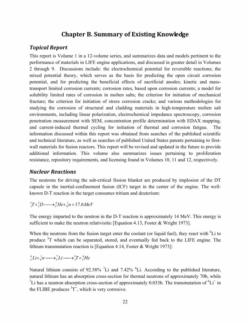
Topical Report This report is Volume 1 in a 12-volume series, and summarizes data and models pertinent to the performance of materials in LIFE engine applications, and discussed in greater detail in Volumes 2 through 9. Discussions include: the electrochemical potential for reversible reactions; the mixed potential theory, which serves as the basis for predicting the open circuit corrosion potential, and for predicting the beneficial effects of sacrificial anodes; kinetic and mass-transport limited corrosion currents; corrosion rates, based upon corrosion currents; a model for solubility limited rates of corrosion in molten salts; the criterion for initiation of mechanical fracture; the criterion for initiation of stress corrosion cracks; and various methodologies for studying the corrosion of structural and cladding materials in high-temperature molten salt environments, including linear polarization, electrochemical impedance spectroscopy, corrosion penetration measurement with SEM, concentration profile determination with EDAX mapping, and current-induced thermal cycling for initiation of thermal and corrosion fatigue. The information discussed within this report was obtained from searches of the published scientific and technical literature, as well as searches of published United States patents pertaining to first-wall materials for fusion reactors. This report will be revised and updated in the future to provide additional information. This volume also summarizes issues pertaining to proliferation resistance, repository requirements, and licensing found in Volumes 10, 11 and 12, respectively.
Nuclear Reactions The neutrons for driving the sub-critical fission blanket are produced by implosion of the DT capsule in the inertial-confinement fusion (ICF) target in the center of the engine. The well-known D-T reaction in the target consumes tritium and deuterium:
MeVnHeDT 6.1710
42
21
31 ++→+
The energy imparted to the neutron in the D-T reaction is approximately 14 MeV. This energy is sufficient to make the neutron relativisitic [Equation 4.13, Foster & Wright 1973].
When the neutrons from the fusion target enter the coolant (or liquid fuel), they react with 6Li to produce 3T which can be separated, stored, and eventually fed back to the LIFE engine. The lithium transmutation reaction is [Equation 4.14, Foster & Wright 1973]:
HeTLinLi 42
31
73
10
63 +→→+
Natural lithium consists of 92.58% 7Li and 7.42% 6Li. According to the published literature, natural lithium has an absorption cross-section for thermal neutrons of approximately 70b, while 7Li has a neutron absorption cross-section of approximately 0.033b. The transmutation of 6Li+ in the FLIBE produces 3T+, which is very corrosive.
23
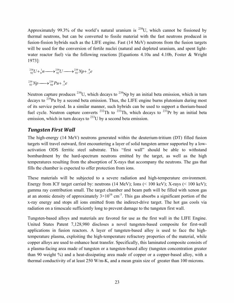
Approximately 99.3% of the world’s natural uranium is 238U, which cannot be fissioned by thermal neutrons, but can be converted to fissile material with the fast neutrons produced in fusion-fission hybrids such as the LIFE engine. Fast (14 MeV) neutrons from the fusion targets will be used for the conversion of fertile nuclei (natural and depleted uranium, and spent light-water reactor fuel) via the following reactions [Equations 4.10a and 4.10b, Foster & Wright 1973]:
eNpUnU 01
23993
23992
10
23892 −+→→+
ePuNp 01
23994
23993 −+→
Neutron capture produces 239U, which decays to 239Np by an initial beta emission, which in turn decays to 239Pu by a second beta emission. Thus, the LIFE engine burns plutonium during most of its service period. In a similar manner, such hybrids can be used to support a thorium-based fuel cycle. Neutron capture converts 232Th to 233Th, which decays to 233Pr by an initial beta emission, which in turn decays to 233U by a second beta emission.
Tungsten First Wall The high-energy (14 MeV) neutrons generated within the deuterium-tritium (DT) filled fusion targets will travel outward, first encountering a layer of solid tungsten armor supported by a low-activation ODS ferritic steel substrate. This “first wall” should be able to withstand bombardment by the hard-spectrum neutrons emitted by the target, as well as the high temperatures resulting from the absorption of X-rays that accompany the neutrons. The gas that fills the chamber is expected to offer protection from ions.
These materials will be subjected to a severe radiation and high-temperature environment. Energy from ICF target carried by: neutrons (14 MeV); Ions (< 100 keV); X-rays (< 100 keV); gamma ray contribution small. The target chamber and beam path will be filled with xenon gas at an atomic density of approximately 3×1016 cm-3. This gas absorbs a significant portion of the x-ray energy and stops all ions emitted from the indirect-drive target. The hot gas cools via radiation on a timescale sufficiently long to prevent damage to the tungsten first wall.
Tungsten-based alloys and materials are favored for use as the first wall in the LIFE Engine. United States Patent 7,128,980 discloses a novel tungsten-based composite for first-wall applications in fusion reactors. A layer of tungsten-based alloy is used to face the high-temperature plasma, exploiting the high-temperature refractory properties of the material, while copper alloys are used to enhance heat transfer. Specifically, this laminated composite consists of a plasma-facing area made of tungsten or a tungsten-based alloy (tungsten concentration greater than 90 weight %) and a heat-dissipating area made of copper or a copper-based alloy, with a thermal conductivity of at least 250 W/m-K, and a mean grain size of greater than 100 microns.
24
The regions separating the heat-resistant tungsten-alloy face and the heat-dissipating copper face is separated by a refractory-metal-copper composite; the refractory-metal-copper composite having a macroscopically uniform copper and tungsten concentration progression and a refractory metal concentration ranging from 10 to 40 volume % throughout material’s thickness of 0.1 mm to 4 mm. The refractory metal phase forms a virtually continuous skeleton in this composite structure. Refractory-metal-copper composites with nearly continuous skeletons can also be produced by pressing powder mixtures or composite powders and sintering. Aside from W-Cu and Mo-Cu composites produced in this way, the use of rolled or extruded Mo-Cu composites has proven to be particularly advantageous.
Suitable tungsten materials for the plasma-facing segment are believed to include monocrystalline tungsten, pure tungsten, AKS (aluminum-potassium-silicate doped) tungsten, UHP (ultra-high-purity) tungsten, nanocrystalline tungsten, amorphous tungsten, ODS (oxide-dispersion-strengthened) tungsten, W-Re, ODS-W-Re and carbide-, nitride, or boride-precipitation-hardened tungsten alloys with preferred a carbide, nitride or boride concentration of between 0.05 and 1 vol. %. Segmentation of the tungsten/tungsten-alloy components is advantageous. As the crack propagation rate of the tungsten components is significantly higher in the direction of deformation than perpendicular to it, it may be advisable in the case of parts exposed to high levels of stress to produce the tungsten parts in such a way that the direction of deformation is perpendicular to the plasma-facing surface. In order to achieve sufficient structural stability and rigidity, a component consisting of a metallic material with strength of more than 300 MPa is bonded to the copper segment. Particularly suitable metallic materials include age-hardened Cu--Cr--Zr, and ODS-Cu materials as well as austenitic steels.
Neutron Multiplication Blanket Current fusion reactor concepts consider the application of beryllium as neutron moderator and neutron multiplier [Ursu 1985, Section 12.5.3, p. 434]. The 14-MeV neutrons from the ICF target bombard beryllium in the neutron multiplication blanket where Be(n,2n)Be reactions moderate their energy and generate approximately 2 neutrons for every one absorbed. Beryllium is one of the best solid moderators and is used either as metallic beryllium or as beryllium oxide. Beryllium has a low absorption cross section, a high scattering cross section, and a high melting point of 885°C (1158K). Beryllium is a light metal with an elastic modulus slightly superior to that of steel, and does not readily oxidize in air.
With the advent of fusion and fusion-fission reactors in the future, beryllium is expected to become and increasingly important material. Published estimates indicate that a fusion reactor generation capacity of one-million megawatts will require approximately 4.6×10⁷ kilograms of beryllium. The availability of this strategic material is discussed by Shedd [2007].
Beryllium is stable under the modest neutron irradiations that have been encountered in conventional nuclear systems, but may be problematic at the fluencies expected in the LIFE

25
engine [Ursu 1985]. Its exposure to neutron fluencies up to 2.3×10²¹ n/cm2 does not entail any sizeable dimensional change, nor does its electrical resistivity and corrosion resistance changes. As for the other properties, the thermal conductivity decreases slightly, the tensile strength increases from 500 MPa to about 714 MPa, whereas the elongation decreases from 1.4 to 0.3 percent. Notably, the hardness increases by about 30%. Also, the generation of helium as a result of irradiation causes beryllium to become brittle.
Beryllium and its salts, including FLIBE and FLINABE are considered very toxic and will have to be handled very carefully. Assuming an eight-hour work day, the maximum allowable concentration of beryllium aerosol in a fusion reactor facility should be no more than 2 micrograms per cubic meter. Exposure of he public should be no more than 0.01 micrograms per cubic meter.
Sub-Critical Fission Blanket WG-Pu and HEU can be digested directly into a molten salt, thereby forming a high burn-up liquid fuel for the direct incineration of old weapons materials. Natural and depleted uranium (Nat-U and DU) can be incorporated into a variety of solid fuels including: TRI-structural ISO-tropic fuel (TRISO); baseball or solid hollow core (SHC); inert matrix fuel (IMF); and granular and powder fuels encapsulated in protective shells.
Fertile & Fissile Material Options
Several types of fertile and fissile materials were considered during the conceptual design of the LIFE engine. Solid uranium fuels could be fabricated from nitrides, oxides, carbides, oxycarbides, silicides, aluminides and metallic alloys. The density and melting points of candidate fissionable fuels are summarized in Table 3, and are listed from the highest to the lowest melting point. Oxides, nitrides and carbides have the highest melting points. Commercial TRISO fuels use a mixed ceramic phase, uranium oxy-carbide (UOC), which appear to minimize thermal migration effects of the kernel.
Compounds such as UF4 and Th4 are soluble in molten salts comprised of lithium fluoride and beryllium fluoride, such as FLIBE [Ursu, Chapter 7, p. 247, 1985]. These dissolved uranium and thorium salts can therefore be used as homogenous liquid-phase fuels, which are immune to radiation damage, but are prone to the precipitation of metallic fission products and plutonium (PuF3). Continuous on-line reprocessing will be required for such fuels, and the potential risk of proliferation may be higher than that of a solid fuel. An obvious exception would be the burning of weapons grade plutonium, where the threat of proliferation will only diminish. If these materials become oxidized, problematic volatile compounds can form. The gaseous UF6 species is very well known, and could form during the inadvertent oxidation of UF4. Such volatilization could be controlled through electrochemical control and manipulation of the uranium oxidation state.

26
Concepts for blanket/coolant materials have evolved over several decades. That evolution is discussed in the book by Ursu [1985], as well as in earlier articles by Grimes and Cantor [1972] and others. The early evolution of these concepts is briefly summarized as follows:
• 1957 (UKAEA, Harwell): 238U – 6Li
• 1957 (KAPL): UO2SO4
• 1965 (MIT): LiF-BeF2-UF4 and LiF-UF4
• 1969 (MIT): 71%LiF-2%BeF2-27%ThF4
• 1970 (MIT): 235U-233U-239Pu-6Li
• 1972 (PNL): Natural Uranium
• 1972 (Grimes et al. at ORNL): Li2BeF4 and LiNaBeF4
Baseline TRISO Fuel for LIFE Engine
Figure 6 shows an enhanced TRISO fuel, which has a more robust SiC capsule than conventional configurations to enable fission-gas containment at very high burn-up. This TRISO configuration is being considered as one possible high burn-up fuel option for the LIFE engine. The enhanced TRISO will have to endure more radiation damage than conventional TRISO fuels, as shown in Figure 7. The experience base for TRISO fuels is limited, with 8 to 20% FIMA demonstrated with low enriched uranium (LEU), and 79% FIMA demonstrated with highly enriched uranium (HEU) [Petti et al. 2004]. These LEU and HEU fuels experienced only approximately 3.5×10²¹ n/cm2, but at a relatively high temperature of 1100 to 1200°C. In contrast, LIFE fuels will experience a much higher neutron dose of approximately 1.2×10²³ n/cm2, but at a much lower temperature of about 700°C. The temperature spike in the fuel pellets that result from the pulse of neutrons entering the fission blanket every 1/20th of a second is approximately 20°C.
Commercial TRISO fuels use a mixed ceramic phase, uranium oxy-carbide (UOC), which appear to minimize thermal migration effects of the kernel. Ultimately, several different types of fertile and fissile materials could be used for fabrication of solid fuels for the LIFE engine. Ultimately, solid fission fuel for the engine could be fabricated from nitrides, oxides, carbides, oxycarbides, silicides, aluminides and metallic alloys. The LIFE engine enable the direct burning of such fuels with no isotopic enrichment or chemical separation, with the potential to attain very high burn-up, which is quantified in terms of fission of initial metal atoms (FIMA).
While the limitations of TRISO fuel at ultra-high burn-up are recognized and acknowledged, this fuel form is being used for the baseline design since the highest level of burn-up has been achieved with it. Based upon a thorough review of the technical and scientific literature, it is believed that an enhanced TRISO particle, based upon fuels already developed by INL, may

27
provide an acceptable option for the nearly complete burning (> 99% FIMA) of weapons-grade plutonium [Petti et al. 2004]. Other potentially superior fuels are being investigated in parallel, and include a new solid hollow core (SHC) fuel, inert matrix fuel (IMF), nano-structural fuels, powdered and granular fuels, and others.
In contrast, serious issues must be dealt with to achieve high-burn-up (> 99% FIMA) during 50 years of operation in a LIFE engine that is optimized to burn depleted uranium (DU). Challenges facing such enhanced high burn-up TRISO fuels in the LIFE Engine include: irradiation-induced damage of fuel materials, including swelling of the SiC and graphite; fuel failure due to the accumulation of noble fission gases such as Kr-85 within the SiC containment capsule; the thermo-mechanical response of non-isotropic PyC layers; which can be mitigated in part with uninterrupted TRISO processing; fatigue driven by thermal pulsing within the engine; thermal migration of kernel inside the SiC capsule, which can be mitigated in part by replacing UO2 with UCO; attack the containment capsule by fission products such as Pd; and abrasion and corrosive attack of the fuel pebble. Table 4 summarizes these challenges, as well as possible mitigation strategies. The detailed research and development plan that will evolve in the future will lead to improved understanding through modeling and experimentation, and will provide the team solid guidance on exactly how to modify the well-established TRISO structure to withstand higher levels of radiation and fission gas buildup expected at such high burn-up.
LIFE TRISO fuel will operate below 1000°C, avoiding the non-saturable void-swelling regime. The fission blanket is expected to operate in the saturable point-defect swelling regime of silicon carbide (SiC), which is shown in Figure 8. Based upon published data for damage levels up to 8.5 displacements per atom (dpa), the swelling of SiC capsule expected to be 0.4 to 0.9 % [Snead et al. 2007]. Data at much higher irradiation levels is desperately needed, and will be generated during future irradiations with three-beam accelerators, high-flux hard-spectrum test reactors, and ultimately, LIFE pilot units. The three-beam accelerators will be used to simultaneously irradiate materials samples helium, hydrogen, and heavy ions to introduce damage.
Based upon a detailed kinetic model that accounts for the growth of dislocation loops, as well as ion-beam irradiation studies at Kyoto University’s DuET facility, irradiation-induced swelling of SiC is expected to reach an asymptotic value of less than approximately one percent (~1%) as the dose increases [Ryazanov et al. 2002]. Model predictions and ion-beam irradiation of SiC show no significant swelling of above approximately 1 displacement per atom (1 dpa), as shown in Figure 9. However, the need to obtain data at higher neutron fluence cannot be overstated.
The anisotropic swelling of the inner and outer pyrolytic graphite (IPyC and OPyC) layers in TRISO particles, as well as the graphite binder in the pebbles, is considered to be a significant barrier to the development of ultra-high burn-up TRISO fuels, as shown in Figure 10. The swelling of the lattice normal to the hexagonal planes (along c-axis) is substantially greater than that parallel to the planes (along a-axis). A material that swells isotropically, and to a lesser

28
extent, is preferable As shown in Figure 11, the fracture strength of irradiated nuclear graphite is expected to be 25 to 45 MPa at 20 to 25 × 1025 n/m2, but may drop at higher doses [Zinkle 2008].
New Production Reactor (NPR) TRISO fuels were subjected to a neutron dose of 3.7×1025 n/m2 (3.7×10²¹ n/cm2), and demonstrated the ability to achieve 64% when exposed neutrons from ATR, and the ability to achieve 79% FIMA prior to fission gas release when exposed to neutrons from HFIR. Differences observed between the experiments done at ATR and HFIR may be attributable in part to the softer neutron spectrum at HFIR. In regard to LIFE, additional testing and data are needed at doses as great as 1027 n/m2 (1023 n/cm2) [Petti et al. 2004].
TRISO fabricated from HEU has achieved relatively high burn-up (79% FIMA) with our failure of the SiC capsule and leakage of fission gas such as Kr-85, as shown in Figure 12. The observed probability of failure appeared to be approximately 1 in 77,500 at this level of burn-up. Achieving such high burn-up with TRISO fabricated with natural or depleted uranium is a much greater challenge. Figure 13 shows fractures in the IPyC and SiC layers of a TRISO particle after reaching 79% FIMA. The observed leakage of fission gas from these particles appears to be due to the pressurization and fracture of the spherical silicon carbide pressure vessel.
One plausible explanation of the failure of the NPR TRISO at 64% FIMA is over pressurization of silicon carbide capsules with fission gas. The failure of these TRISO particles may coincide with the point where the SiC wall stress exceeds the ultimate tensile stress (UTS) of the material, as shown in Figure 14. Thus, one practical method of mitigating the failure may be to thicken the SiC wall.
Additional engineering of TRISO technology developed by DOE complex (INL, ORNL, BWXT and others) could lead to much higher burn-ups of natural and depleted uranium, with the mechanical ability to accommodate 95% to 99% FIMA. Enhanced TRISO particles have been designed with enough SiC wall thickness for fission-gas containment at 99.9% burn-up. Figure 15 shows a prediction of SiC wall stress verses fuel burn-up for this enhanced fuel. Crack initiation at defects in the SiC capsule must be accounted for in the development of enhanced TRISO fuels, and has now been modeled with finite element codes such as ALE3D and ABAQUS, as shown in Figure 16. The enhanced TRISO fuel will also experience dynamic stress due to thermal pulsing at 10 to 20 Hz in the LIFE Engine, which may cause thermal fatigue. Numerical analysis indicates fuel design will endure 10 to 20 Hz thermal pulse, as shown in Figure 17 [P. Damange, J. Marian, M. Serrano de Caro, LLNL, 2008]. Note that these models also incorporate the effects of radiation swelling on fuel materials; improvements in predictive ability over the coming years will increase confidence and lead to far better fuel designs.
Survival of the SiC capsule is complicated by reactions involving fission products such as Pd, which can be understood with the help of the phase diagram shown in Figure 18 [Okamoto 2000]. Deleterious low-melting eutectics form between fission products and encapsulation materials. A frequently cited example is the Pd-Si reaction. Pd5Si phase formation threatens

29
TRISO performance above the melting point of Pd5Si, which is 836°C. Thermal migration of kernal in temperature gradient can bring such fission products in close proximity of the SiC. Mitigation includes the use of sacrificial SiC in (or around) the kernel and a ZrC diffusion barrier. It is important to note that the TRISO operating temperature is expected to be below the melting point of deleterious phases such as Pd5Si. Other possible phase transformations in the TRISO fuel are being predicted with THERMOCALC, and require knowledge of various binary pairs (C-Pu, O-Pu, O-U, Pu-U, Pd-Si, Pd-C, Si-C, etc.) as shown in Figure 19 [L. Kaufman, P. Turchi, LLNL, 2008].
The baseline TRISO fuel has several potential limitations. The mass fraction of fertile material in both conventional and enhanced TRISO fuel is limited by the packing efficiency of small TRISO particles (1-mm) in the larger TRISO pebble (2-cm), which is believed to be approximately 30%. The strength of the pressure boundary is limited by the properties of CVD silicon carbide. Furthermore, there is no means to control the buoyancy of the pebbles in the molten salt coolant.
Solid Hollow Core Fuel
New fuel designs will enable us to overcome limitations of the current high burn-up solid fuels such as TRISO. The new solid hollow core (SHC) design being developed by LLNL may provide benefits unattainable with more conventional pebbles [Farmer, Latkowski and Abbott 2007-2008]. For example, higher mass fractions of fertile material can be incorporated into SHC than TRISO fuel. The predicted wall stresses in the SHC fuel at fission gas pressures corresponding to 20, 40, 60, 80 and 99.9% FIMA are shown in Figures 21 and 22, and are substantially less than those in comparable TRISO fuels [P. Damange, J. Marian, M. Serrano de Caro, LLNL, 2008]. The use of sacrificial SiC in the SHC should help mitigate attack of fuel materials by fission products. The specific use of sacrificial SiC in solid fuels is attributed to R. J. Lauf et al. [1984].
Fuel Fabrication Processes
The conceptual process for fabrication of enhanced TRISO fuel for LIFE from natural and depleted uranium is based upon conventional TRISO processing technology, and is shown in Figure 23. A process for the conversion of LWR spent nuclear fuel into IMF-type LIFE fuel is shown in Figure 24. Molten salt fuels do not experience radiation damage, and enable direct digestion of materials such as WG-Pu and HEU for incineration, and will be discussed in the following section entitled Coolants and Liquid Fuels.
Coolants and Liquid Fuels
Coolants
High-temperature liquid-phase coolants appropriate for heat transfer in nuclear power systems such as the LIFE engine fall into two broad categories, liquid metals and molten salts. Liquid metal include Hg, Na, K, Pb, Bi, Pb-Bi, Sn, Li, Li-Al, Pb-Li, Sn-Li, and others. Molten salts

30
include FLIBE (2LiF + BeF2 = Li2BeF4), FLINABE (LiF + NaF + BeF2 = LiNaBeF4), FLINAK (LiF + NaF + KF) and others (for example, 24NaBF4 + 24NaF). FLIBE has been proposed for use in the primary coolant loop of the LIFE engine, while beryllium-free FLINAK has been proposed for use in the secondary loop. The lithium in the primary loop coolant will enable tritium breeding, while the beryllium helps moderate neutrons.
Molten salt coolants are less prone to catch fire than the liquid metal coolants, and can be used to breed tritium via the transmutation of lithium. A binary mixture of BeF2 and LiF produces the eutectic composition Li2BeF4, which has a relatively low melting point of less than 400°C, as shown in Figure 25. The formula weight, density, melting point and boiling point of several of these candidates are summarized in Table 5 [Williams et al. 2006; Moir et al. 1985; Wright and Foster 1973; Rosenthal et al. 1971]. Pure FLIBE has relatively low viscosity, comparable to kerosene at ambient temperature, and therefore would be expected to flow well.
Note that several other programs have investigated the use of molten fluoride salts. FLIBE is considered as a candidate material for tritium breeding in a fusion liquid due to its chemical stability and low electrical conductivity. The Jupiter-II Irradiation Tests for Fusion Research also focused on the use of FLIBE [Petti et al. 2006]. It was selected for the conceptual design of the Force Free Helical Reactor (FFHR). The tritium release behavior and the corrosion of the structural materials by FLIBE were key to success in this application. In this particular design, a ferritic steel (Fe-9Cr-2W) and a vanadium alloy (V-4Cr-4Ti) are the candidate materials for the blanket structure [Nishimura et al. 2001].
Investigators at the University of Tokyo (YAYOI) placed a Monel crucible with 100 to 300 grams of FLIBE in a fast-neutron reactor and heated the salt to 873K [Nishimura et al. 2001]. The neutron flux during these irradiations was 108 to 109 n cm-2 sec. At hydrogen partial pressures above 1000 Pa, the primary tritium-bearing species responsible for tritium release is gaseous diatomic HT. These investigators determined the normalized release rates for tritium in flowing stream of helium purge gas with various concentrations of hydrogen. The normalized tritium release rate dropped dramatically below hydrogen partial pressures of 1000 Pa. Steady state was achieved after approximately 120 to 140 minutes of purging.
Unfortunately, the transmutation of lithium in this coolant produces very corrosive tritium fluoride species (TF), which behaves like hydrofluoric acid and can rapidly degrade structural materials. Thermal neutrons react with Li+ and convert it to T+, which then reacts with fluoride anions to form gaseous TF. Exchange reactions between tritons (T+) and diatomic hydrogen (H2) formed protons (H+) and diatomic HT. The corrosion of structural components of the LIFE engine in contact with this coolant must be understood.
It may be possible to control the release of tritium from the FLIBE blanket through the manipulation of electrochemical oxidation and reduction reactions, using an on-line electrolytic

31
cell. The reduction of tritons (T+) in such a cell would simultaneously remove the threat of acidic TF, while enabling the extraction of tritium from the salt for storage in solid-state media.
Liquid Fuels & Continuous On-Line Reprocessing
If a homogenous liquid fuel is desired, fertile/fissile materials can be dissolved in these molten salt mixtures. Unlike solid fuels, molten salts with dissolved uranium, thorium and plutonium will not be structurally damaged by long-term exposure to neutron bombardment. From a purely technical point of view, such liquid fuels might therefore serve as ideal fuels for achieving nearly complete burn-up. Such molten salt fuels have been considered for graphite-moderated molten-salt breeder reactors that operate on the thorium-uranium fuel cycle, and enable continuous reprocessing of the fuel. Reprocessing is used to keep fission products at desirable levels. A widely referenced fuel salt consists of Li2BeF4 (FLIBE) with dissolved fissile UF4 and a blanket salt consisting of Li2BeF4 with dissolved fertile ThF4. These conceptual designs assumed that NaBF4 and NaF2 would be used as secondary loop coolants. FLINABE and FLINAK based systems are also possible.
These liquid-phase solutions are very complex. In-depth understanding must be developed through application of internationally accepted predictive codes such as THERMOCALC to predict the formation of various phases, including precipitates such as plutonium trifluoride (PuF3). The prediction of phase diagrams for complex liquid fuels, with large numbers of fission products, requires that the phase diagrams for several binary pairs of salts first be developed. For example, equilibrium phase diagrams have already been predicted for: BeF2-LiF (FLIBE), BeF2-ThF4, BeF2-UF4, BeF2-ZrF4, LiF-PuF3, LiF-ThF4, LiF-ZrF4, ThF4-UF4 and several other systems. The LIFE Project has recently predicted a phase diagram for the most basic FLIBE-based liquid fuel, assumed to consist primarily of lithium, beryllium, uranium and plutonium fluorides. This phase diagram is shown in Figure 26, and reveals regions of stable operation for such liquid fuels. Such systems would have to be operated at compositions and temperatures where no solid-phase precipitates form. Other continuous molten-salt processing schemes are reviewed elsewhere by Farmer, Shaw, Moir and Halsey [2008].
Most of our practical knowledge pertaining to liquid fuel comes from the development of the molten salt breeder reactor (MSBR) [Foster and Wright 1973]. The MSBR concept depends upon molten fluoride salts containing 7LiF, BeF2, ThF4 and 233UF4 being pumped through a graphite moderated core where heat released by fission will raise the salt temperature to 700°C (~1300°F), close to the operating temperature of the LIFE engine. The heated salt then passes through an intermediate heat exchanger where its enthalpy is reduced by transfer of heat to a secondary salt, sodium fluoroborate, which in turn may transfer energy to steam at 3500 psia and 540°C (~1000°F).
Initially, a two-salt MSBR design was favored, with a fuel salt containing only fissile UF4 and no fertile ThF4, and a blanket salt containing only ThF4 and no UF4. The fuel and blanket salts were

32
passed in close proximity to one another inside a graphite moderator block, where uranium-233 was bred from thorium. Unfortunately, problems due to dimensional instability of the graphite moderator block after long-term neutron irradiation were encountered.
In the case of the two-salt MSBR, a relatively simple on-line fuel reprocessing plant was enabled by the physical separation of fissile and bred uranium in the graphite moderator block [Figure 13.31, Foster and Wright 1973]. In the conceptual on-line salt reprocessing plant, fuel salt is fluorinated to convert dissolved UF4 to gaseous UF6, thereby allowing uranium separation from the liquid stream. The remaining salt is separated from rare earth and other fission products by vacuum distillation. Approximately 5% of the fuel salt is discarded in this conceptual process, with the need for LiF and BeF2 makeup. In contrast, the blanket salt is fluorinated primarily for the removal of bred uranium from the fertile thorium. Approximately 5% of the blanket salt is also discarded in this process, with the need for LiF, BeF2 and ThF4 makeup. The total salt leaving the loop is approximately 8%. A LIFE engine with liquid fuel would require a separation process for the continuous removal of rare earth fission products to prevent the precipitation of PuF3. Similar salt removal would therefore be expected in a LIFE engine.
A reactor design with a single-salt two-region core and an easily replaceable graphite core assembly evolved, due to the problems anticipated with dimensional stability of the graphite in the two-salt design. This design eliminated the need for complicated flow paths inside the moderator block. The value of k∞ was found to peak at approximately 4% salt content and drop to below unity at approximately 18% salt content. It was found that a core with 13% salt content would be critical with k∞ of 1.034, while a reflector region having less than 37% salt content would be sub-critical with k∞ of 0.392. A breeding ratio of 1.07 to 1.08 was predicted for such a system with low fuel costs and small fuel inventories.
In the conceptual MSBR, the strong neutron capture of protactinium-233 (σa = 43b) in the core of the core leads to the production of protactinium-234, which in turn would decay to non-fissionable uranium-234. It is therefore be necessary to remove 233Pa (27.4-day half life) from the core so that it has time to decay to fissionable 233U. A liquid-to-liquid extraction process may be the best means for separating protactinium and uranium from the molten salt. An electrolysis process is then used to selectively recycle the uranium from salt in the decay tank to the MSBR fuel salt. Residual protactinium is then trapped in solidified salt for discarding.
The removal of noble gases such as xenon from the core of the MSBR is also essential for efficient breeding. Specifically, helium purging is used to remove xenon-135 (σa = 2.72×10⁶b), reducing the concentration of this gaseous fission poison by an order-of-magnitude (×10).
Tritium Recovery & Permeation
Tritium recovery and permeation from molten fluoride salts in the molten salt breeder reactor (MSBR) has been previously studied, and is believed to be analogous to the application of such salts in the LIFE engine [Foster and Wright 1973; Moir et al 1984]. In the case of the MSBR, it

33
was assumed that tritium was dissolved in the molten salt, with the formation of tritium fluoride (TF) suppressed. It was believed that tritium in the MSBR would permeate through the hot steel tubes of heat exchangers and steam generators at a rate of approximately 1 gram per day in the absence of permeation barriers, assuming that 1% of the helium coolant flow rate was processed for tritium recovery at 90% efficiency per pass (90% separation efficiency). Tritiated water in the steam system was considered to be a personnel hazard at concentration levels well below one part per million (< 1 ppm), a level that would be reached quickly without costly isotopic processing. The use of permeation barriers (coatings) on MSBR and steam generator tubes was said to be able to reduce the leak rate of tritium into the steam system by two orders-of-magnitude (×100). For the option wi\th the lowest estimated leak rate of 55 curies per day, it may be possible to purge the steam system continuously to prevent the accumulation of tritiated water.
Selection of Structural and First Wall Materials The upper operating temperature limit of structural materials for reactors is determined by one of several factors, all of which become more pronounced with increasing exposure time, and which include: (1) thermal creep (grain boundary sliding or matrix-diffusion creep); (2) high temperature He embrittlement of grain boundaries; (3) cavity swelling (particularly important for SiC and Cu alloys); and (4) coolant compatibility/corrosion issues. In many cases, the upper temperature limit will be determined by coolant corrosion/compatibility rather than by thermal creep or radiation effects.
Broad ranges of high-melting radiation-tolerant structural material have been proposed for fusion-fission reactor structures. The properties of these materials are generally compromised by radiation damage. The upper operating temperature for each candidate structural material is summarized as follows:
• Refractory Metals: T < 4000°C
• Carbides: T < 4000°C
• Nitrides: T < 3500°C
• Borides: T < 3500°C
• Oxides: T < 3000°C
• Intermetallics: T < 3000°C
• Silicides: T < 2500°C
• Sulfides: T < 2500°C

34
• Nickel-Based Alloys (Hastelloys A, N, X; Inconels): T < 650-800°C
• Iron-Based Austenitic Steels (9-12% Ni): T < 600-650°C
• Other Steels (5-15% Cr): T < 500-600°C
• Ferritic Steels (3-3.5% Cr): T < 400-550°C
Metallic alloys that have been considered for structural components in variouss nuclear reactor applications include austenitic stainless steels, ferritic steels, and refractory metal alloys such as V-Cr-Ti, which are summarized in Tables 6 and 7. The austenitic steels are prone to extreme swelling and high temperature thermal creep, as will be discussed subsequently. Ferritic steels show relatively little swelling during neutron irradiation, and can be enhanced by inclusion of a nano-dispersion of oxide particles. The refractory may be useful at higher temperatures than the levels that can be attained with austenitic and ferritic steels. Refractory metals are found in Groups IVB and VB of the periodic table, and include Nb, Ta, Cr, Mo, and W, as serve as the basis of refractory alloys. Tungsten-based alloys and materials are frequently preferred for first-wall applications in fusion reactor designs.
Iron-Based and Nickel-Based Steels
The performance of iron and nickel based alloys in nuclear applications is discussed in substantial detail by Ursu [1985, Section 12.5.2, p. 441-445]. Insights from Ursu are summarized in this section. The mechanical and corrosion performance, ease of fabrication, and relatively low cost of iron- and nickel-based steels make them logical choices for the fabrication of reactor structural components. The addition of refractory metals such chromium enhances high-temperature tensile strength, as well as corrosion resistance, though such performance is generally compromised by irradiation. The performance of iron and nickel based alloys in nuclear applications is discussed in substantial detail by Ursu [1985, Section 12.5.2, p. 441-445]. Insights from Ursu are summarized in several of the following paragraphs.
In the temperature range of 400-550°C, pearlitic-ferritic steels are frequently used. To extend the range of operating temperatures to 450-550°C, it is necessary to increase the chromium (Cr) content to 3-3.5 weight percent (3-3.5%). Carbide-forming elements such as molybdenum, tungsten, and vanadium (Mo, W, and V) are also beneficial for extending the range of operating temperature. These steels are said to behave acceptably with hydrogen within this range of temperatures.
Ferritic stainless steels are chromium-containing alloys with body-centered cubic (bcc) crystal structures [Davis 1995]. Chromium content is usually in the range of 10.5-30 weight percent (10.5-30%). Some grades contain molybdenum, silicon, aluminum, titanium, or niobium (Mo, Si, Al, Ti, or Nb) to confer particular characteristics. Ferritic alloys have good ductility and

35
formability, but high-temperature strengths are relatively poor compared to those of austenitic grades. Toughness may be somewhat limited at low temperatures in heavy sections.
Annealed ferritic stainless steels usually have yield and tensile strengths of 240-380 MPa (35-55 ksi) and 415-585 MPa (60-85 ksi), respectively. Ductilities end to range from 20 to 35 percent. More highly alloyed ferritic stainless steels may have yield and tensile strengths as high as 515 MPa (75 ksi) and 655 MPa (95 ksi), respectively. These alloys are not strengthened by heat treatment or cold working. The strain-hardening rates of ferrite are relatively low and cold work lowers ductility.
Whereas martensitic stainless steels offer only moderate corrosion resistance, that of ferritic stainless steels can range from moderate for lower alloyed grades, to outstanding for more highly alloyed grades. Typical applications for ferritic stainless steels include equipment for handling oxidizing acids and organic acids, food processing equipment, and heat exchangers and piping used in seawater.
To enable operation at higher temperatures, in the 500-600°C range, additional chromium is required. Chromium additions of 5-15 weight percent (5-15%) increase the re-crystallization temperature and prevent plastic deformation. For example, enhanced steels with 12 weight percent chromium (12% Cr) have been shown to behave well at an applied stress of 200 MPa and a temperature of 500°C for 10.000 hours At the upper limit of this temperature range, molybdenum, tungsten, vanadium and niobium (Mo, W, V or Nb) are needed.
Austenitic steel with 18% Cr, 9% Ni and 1% Ti, with carbides, have been shown to be capable of withstanding an applied stress of 200 MPa at 630°C for 10,000 hour. Nickel alloys can be used as structural materials at temperatures up to 700°C, nickel-cobalt alloys can be used up to 800°C, and chromium alloys can be used up to 1100°C.
Refractory steels are used in the temperature range 900-1200°C, but cannot serve reinforcement purposes. Their strength depends upon temperature and increases with the rise in Cr concentration.
Oxide Dispersion Strengthened Ferritic-Martensitic Steels
New oxide dispersion strengthened (ODS) ferretic-martensitic (FM) steels have been developed specifically for a variety of nuclear applications, including cladding for fuel in fast reactors. These alloys are therefore considered to be good candidates for cladding for fuel in fast-flux reactors, as well as for the construction of LIFE engine structural components. These alloys exploit the ability of the ferritic matrix to withstand extreme neutron irradiation with relatively little swelling. Oxide dispersion strengthening with Y2O3 or TiO2 nanoparticles enhances tensile strength and creep resistance at high temperature [Allen et al. 2005]. These alloys are therefore considered to be good candidates for construction of structural components of the LIFE engine.

36
The ODS FM steels known as Kobe 12YWT and 9Cr-ODS have demonstrated exceptional tensile strength and creep resistance at relatively high temperature, as shown in Figures 27 and 28 [Ukai and Fujiwara 2002; Klueh et al. 2007]. To further emphasize this point, the yield strengths and elongations as functions of test temperature for several additional ODS steels, including as-received EUROFER 97, CRPP ODS EUROFER97 with 0.3 wt. % Y2O3 and CRPP ODS EUROFER97 with 0.3 wt. % Y2O3 and 0.3 wt. % TiO2 are shown in Figure 29 [Schaublin et al. 2006].
Given the thermal pulsing of the LIFE Engine, the resistance of materials of construction to thermal fatigue is also of interest. ODS FM steels appear to have much longer fatigue life than conventional ferritic steels such as modified 9Cr-1Mo steels, as shown in Figure 30. Predictions based upon regression analysis of data for Nf < 100,000 cycles. Strain-controlled low-cycle fatigue tests were conducted for 9Cr-ODS and 12Cr-ODS at 873-1023K. The total strain ranges were controlled from 0.5 to 1.5% with a strain rate of 0.1% per second. Corresponding plastic strain ranged from 0.01 to 1%. The ODS has longer fatigue life than modified 9Cr-1Mo ferritic steel. The oxide dispersion strengthening prevented softening or hardening during cycling [Ukai and Ohtsuka 2007].
Alternatives to Steel
Zinkle et al. have performed and outstanding critical analysis of the operating temperature windows for nine candidate structural materials for fusion reactors [Zinkle et al. 2004]. These include: four reduced-activation structural materials (oxide-dispersion-strengthened and ferritic/martensitic steels containing 8-12%Cr, V-4Cr-4Ti, and SiC/SiC composites), copper-base alloys (CuNiBe), tantalum-base alloys (e.g. Ta-8W-2Hf), niobium alloys (99Nb-1Zr), and molybdenum and tungsten alloys. The results are compared with the operating temperature limits for Type 316 austenitic stainless steel. Several factors define the allowable operating temperature window for structural alloys in a fusion reactor. The lower operating temperature limit in all body-centered cubic (bcc) and most face-centered cubic (fcc) alloys is determined by radiation embrittlement (decrease in fracture toughness), which is generally most pronounced for irradiation temperatures below similar to 0.3 TMP where TMP is the melting temperature (Figure 4). The lower operating temperature limit for SiC/SiC composites will likely be determined by radiation-induced thermal conductivity degradation, which becomes more pronounced in ceramics with decreasing temperature.
Vanadium Alloys
Vanadium alloys have been investigated for structural and first-wall applications in fusion reactors [Smith et al. 2000]. Insights from Smith et al. are summarized in this section. These refractory alloys provide favorable safety and environmental features such as low long-term activation, low decay heat and contact dose, and the potential for recycle. Vanadium alloys discussed by these investigators cover a broad range of compositions, V-(0-15)%Cr-(1-20)%Ti-(0-1)%Si, with particular emphasis given to a reference alloy, V-4Cr-4Ti. The three key alloying

37
elements, vanadium, chromium and titanium, are mutually soluble in each other at elevated temperatures, and they all exhibit favorable low-activation characteristics.
Vanadium alloys with a few percent titanium are resistant to irradiation-induced swelling and embrittlement at projected operating temperatures, and are believed to be compatible with liquid-metal blanket/coolants. Helium and hydrogen transmutation rates in vanadium alloys are substantially less than those for other candidate materials exposed to high-energy neutrons characteristic of deuterium-tritium plasmas. Irradiation does harden the materials. For example, the yield stress of V-4Cr-Ti increases from the pre-irradiation level of 200-300 MPa to 600-700 MPa at a damage level of approximately 30 dpa, and temperatures of 430 to 600°C.
The primary thermo-mechanical treatment of these alloys is a solution anneal at approximately 1000°C for one hour. Properties are relatively insensitive to annealing conditions for 950-1100°C for 0.5-2 hours. Thermal aging at temperatures ranging from 500 to 1000C, for exposure times up to 5000 hours, show no significant grain growth (grain size 20 ± 2 µm). In summary, candidate vanadium alloys exhibit good resistance to irradiation damage at temperatures of interest and offer a potential for long operating lifetime.
Other important physical properties of these candidate materials are summarized in Table 6 [Smith et al. 2000]. In particular, the coefficient of thermal expansion of V-Cr-Ti is lower than that of austenitic and ferritic steels, which would help alleviate thermal stress and associated environmental cracking, and the thermal conductivity is significantly higher, which would help alleviate concerns regarding heat transfer. This could make these materials good choices in applications where thermal pulsing is determined to be problematic.
Molybdenum Alloys
Molybdenum alloy with small additions of titanium, zirconium and carbon, such as 99.4%Mo-0.5%Ti-0.08%Zr-0.01%C, have good strain endurance and fracture toughness at high temperature. However, their susceptibility to oxidation requires that it be coated with thermal-spray coatings of Si-Al-Co. Other cladding is also possible. Additions of rhenium have been used to improve the ductility and fabricability of molybdenum alloys. Specific Re-containing molybdenum alloys that have been developed include: Mo-7Re (13 wt. % Re); Mo-27Re (42 wt. % Re); and Mo-30Re (45 wt. % Re). After neutron irradiation of Mo-27Re and Mo-30Re at 750 to 1075°C, MoRe3 (Chi phase) precipitates formed at grain boundaries and on the surface at a damage level of 1.5 dpa; these precipitates were not observed in Mo-7Re [Ursu 1985]. Neutron activation may also pose challenges.
Niobium Alloys
These materials also have good strain endurance and fracture toughness. Some of the best tensile properties obtained with niobium-based alloys have been reported with: (1) Nb-15%W-3%Ti-1%Zr and (2) Nb-10%-3%Ti-1%Zr. Titanium additions have enhanced the hardness of these

38
alloys, and have improved their refractory properties, allowing them to operate at temperatures as high as 1300°C. These materials tend to have better ductility than Mo alloys. Furthmore, these materials can be prepared using cold and hot pressing. Furthermore, argon arc welding is possible. Coatings of silicon have been used to prevent high temperature oxidation [Ursu 1985].
Other Advanced Materials of Interest
The LIFE engine will push crystalline engineering materials to their limits of radiation tolerance. The intense neutron bombardment will displace atoms from lattice sites numerous times, and may eventually convert crystalline materials into an amorphous state, with substantial helium and hydrogen implantation. Since a completely amorphous material may evolve at the extremes of neutron bombardment, the search for any new solid-phase material with immunity to extreme neutron irradiation should include amorphous materials (expected end state). Neutron bombardment would not displace atoms from lattice sites since none exist. The challenge in the development of radiation tolerant amorphous metals will be the attainment of high fracture toughness, and incorporation of features that enable either trapping of large quantities of helium and hydrogen, or that enable the rapid transport of these species out of the matrix.
In addition to the possible application as radiation-tolerant structures, amorphous materials may also have other important applications in the LIFE engine. For example, the high boron content of Fe49.7Cr17.7Mn1.9Mo7.4W1.6B15.2C3.8Si2.4 (SAM2X5) makes it an extremely effective neutron absorber for thermal neutrons, and suitable for criticality control applications [Farmer et al. 2007-2008]. Other yttrium-containing amorphous metals such as SAM1651 could be optimized for the absorption of fast neutrons by substituting Gd for Y or other alloying constituents, and should be explored for LIFE shielding.
Average measured values of the neutron absorption cross section in transmission (Σt) for Type 316L stainless steel, Alloy C-22, borated stainless steel, a Ni-Cr-Mo-Gd alloy, and SAM2X5 have been determined to be approximately 1.1, 1.3, 2.3, 3.8 and 7.1, respectively. This material and its parent alloy have been shown to maintain corrosion resistance up to the glass transition temperature, and to remain in the amorphous state after receiving relatively high neutron dose.
Materials used in criticality control applications must be relatively stable during irradiation with thermal neutrons. Melt-spun ribbon samples of various iron-based amorphous metals were subjected to high neutron dose in the 1.5 MW TRIGA reactor at McClellan Nuclear Radiation Center (MNRC) [22]. The neutron flux was 1.6×10¹⁰ n cm-2 sec-1. Samples were irradiated for three different times: duration of 1st irradiation was 44 minutes; duration of 2nd irradiation was 132 minutes; and duration of 3rd irradiation was 263 minutes. The corresponding neutron doses were: 4.3×10¹³ n cm-2, 1.3×10¹⁴ n cm-2 sec-1 and 2.6×10¹⁴ n cm-2, respectively. These doses are equivalent to approximately 670, 2000 and 4000 years inside the waste packages designed for emplacement at Yucca Mountain. An exposure corresponding to a 4000-year service life does not cause any detectable, deleterious phase transformations.

39
Radiation Damage of Engine Materials
Effect for Radiation on Structural Steels, Refractory Alloys and Ceramics
Austenitic stainless steel (316), high-strength ferritic steel (HT-9), a refractory V-Cr-Ti alloy, and silicon-carbide, all of potential interest for application in the LIFE engine, have been irradiated with values of the radiation damage rate, helium transmutation rate, hydrogen transmutation rate, and nuclear heating rate measured. Irradiations were done with 14-MeV neutrons at a superficial power density of approximately 1 MW/m2 for 1 year. These data are tabulated in Table 7 [Smith et al. 2000]. In general, ferritric stainless steels exhibit much less irradiation-induced swelling than Type 316 austenitic stainless steels, as shown in Figure 31 [Gelles 1996; Toloczko 2000; Klueh & Harries 2001; Zinkle 2008].
Annealed and aged ferritic stainless steel with fine niobium carbide (NbC) precipitates and relatively coarse Laves-phase particles was bombarded with a 4-MeV beam of iron ions. The damage level was 100 displacements per atom (100 dpa) at 400-600°C. Much of the damaged structure consisted of dislocation tangles that coarsened with increasing temperature. Cavity formation began at 450°C, appeared to peak at approximately 535°C, and was absent at 600°C. The maximum swelling observed during these tests was only 0.2 percent (0.2 %). The Laves particles exhibited recoil dissolution and restructuring [Farrell and Lee 1986].
Bombardments with iron, helium and deuterium (Fe, He, and D) beams or iron and helium (Fe and He) beams, at ratios of 10 and 45 atomic parts per million (appm) He/dpa, introduced high concentrations of small bubbles and comparatively few large bias-driven cavities. The latter were initiated at bubble clusters on niobium carbide (NbC) particles. The maximum extent of swelling was 0.75% and occurred at 550°C. Recoil dissolution of the Laves phase was retarded by the gases. Large critical cavity sized and an unbalanced dislocation and cavity sink strengths contributed to low swelling of this alloy. Such behavior makes dispersion strengthened ferritic steels generally attractive for LIFE applications.
Effect for Radiation on Oxide Dispersion Strengthened (ODS) Ferritic Steels
ODS ferritic steels have even better resistance to irradiation-induced damage than conventional ferritic steels without oxide dispersion strengthening. The alloy known as 9Cr-ODS was irradiated with Ni ions at 500°C and showed no detectable void formation at: 0, 5, 50, and 150 dpa, as shown in Figure 32. The effect of ion-beam irradiation on the oxide particles was also studied. The average size of these particles decreased from 11.7 nm for the un-irradiated case to 9.3 nm for the irradiated case at 150 dpa, as shown in Figure 33 [T. R. Allen et al. 2005]. Dispersions of nano-precipitates have also been shown to mitigate irradiation-induced swelling attributable to helium, as shown in Figure 34. Helium appears to be trapped at nano-precipitates in the matrix [Mansur and Lee 1991].

40
ODS ferritic steel has been used successfully to fabricate prototype fuel pins for testing in Russia’s BOR-60 reactor, a sodium-cooled fast reactor [Ukai et al. 2005]. No failures were observed at 5% burn-up (5% FIMA) and 25 displacements per atom (25 dpa). Tests are underway at this reactor which will provide data at 15% FIMA and 75 dpa. ODS alloys appear very resistant to irradiation effects, including high He levels, with a generally good balance of properties, and thus appear ideally suited for Chamber wall applications to 150 displacements per atom (150 dpa) and 1500 atomic parts per million helium (1500 appm He).
Friction stir, inertial and pressurized resistance provide best results Y2O3 particles remain in weld. Figure 35 shows a longitudinal cross-section in the vicinity of welded 9Cr-ODS steel cladding and its end-plug joined with pressurized resistance welding. Figure 36 shows fuel pins with ODS steel cladding and welded end-caps. Fuel pins with ODS steel cladding and welded end-caps, joined with pressurized resistance welding are being tested in BOR-60 reactor: 5% FIMA and 25 dpa were achieved in 2004; 15% FIMA and 75 dpa were achieved in 2008. To the best of our knowledge, no failures of the base metal or welds were experienced at 75 dpa [Ukai et al. 2005]. Others have also successfully joined ODS FM steels using industrial welding processes [Wright and O’Donnel].
Other approaches to dispersion-strengthening also exist, such as thermomechanical treatment (TMT). The microstructure of 9-12% Cr steels has been improved dramatically with hot rolling, which has become known as thermomechanical treatment (TMT). TMT has been used to process 9Cr-1Mo and 12 Cr steels, thereby forming precipitates at dislocations, as shown in Figure 37. Dispersions of precipitates produced with TMT are much finer than those observed in conventionally processed 9-12 Cr steels, and mechanical properties are substantially improved. [Klueh et al. 2005 & 2007].
Effect of Radiation on Nickel-Based Alloys
The irradiation induced swelling of austenitic nickel-based Inconel 600 and Type 316 stainless steel reflector components was studied in detail more than 20 years ago [Makenas et al. 1986, Table 1, Figure 11]. Transmission electron microscopy samples of Inconel 600 wee prepared from two of the swelling samples used to generate the data in Table 8. Limited void swelling was found in the low neutron fluence specimen, while extensive voidage was found in the higher fluence, middle-of-core specimen. Irradiation-induced swelling of nickel-based austenitic steels such as Inconel 600 exceeds 5% at 9×10²² n cm-2 and E > 0.1 MeV. Makenas et al. also discussed the implications of swelling on the performance of the reflector assemblies. Such swelling will probably make such austenitic nickel-based alloys unacceptable for widespread application in the LIFE engine.
The voids exhibit the truncated octahedral shapes normally found in face-centered cubic alloys. Neither transmission electron microscopy (TEM) nor the subsequent topical metallographic examination for second phases were helpful in determining the irradiation temperature of these

41
specimens since Inconel 600 is not prone to temperature-dependent phase changes, which might indicate a specific temperature.
Effect of Radiation on Beryllium Neutron Multiplier
The general experience with beryllium (Be) is that it will swell and crack after receiving relatively low radiation doses, and that these problems will preclude its use for any structural function at doses as high as 200 dpa [Moir et al. 2007]. Beryllium swells by T and He produced during transmutation. At approximately 600°C, beryllium begins to release tritium (T), and continues the release up to 900°C. If beryllium is used only for non-structural components, such as pebbles or high-porosity metallic foams, with no requirements for strength and stability, problems associated with radiation-induced swelling may be inconsequential [A. Caro et al. 2007]. In summary, the integrity of Be components in the neutron multiplication blanket remains a worrisome problem that requires substantial attention.
Corrosive Attack of Engine Materials
Corrosion Mechanisms
The steels used for construction of the LIFE engine must be able to withstand high temperatures without melting or excessive thermal creep. Chromium has been added to many of the structural steels of interest to enhance both high-temperature mechanical properties, as well as oxidation and corrosion resistance. Table 9 provides some general guidance on acceptable ranges of composition for refractory oxidation-resistant steels. An alloy 0.35 to 0.45% for carbon, 2 to 3% for silicon, and 8 to 10% for chromium is suggested for operation at 850°C, close to the current design temperature of the LIFE Engine. The concentration of chromium in the ODS FM steels proposed for construction of the LIFE Engine fall within the recommended range.
In addition to having good high-temperature mechanical properties and being able to withstand oxidation, the structural materials used for construction of the LIFE Engine will have to withstand corrosive attack by the FLIBE (Li2BeF4) coolant. The corrosion and chemical compatibility of candidate metals and alloys is summarized in Table 10, entitled Materials Compatibility with Li2BeF4 Coolant, and is consistent with assessments in the literature [Ursu 1985, Section 12.4.4, Table 12.17, p. 436].
The corrosion of structural materials are due to the oxidative dissolution of reduced alloy constituents (M) with the high-temperature molten fluoride salt (XF), as described by Cheng et al. [2003]:
XMFXFM +→+
In this reaction, X represents lithium, sodium, beryllium, or transmutation products, such as tritium. The transmutation of lithium produces hydrogen isotopes which react with free fluoride

42
to form acid (HF, for example), making the blanket and coolant much more corrosive than it would otherwise be.
The relative corrosion susceptibility of refractory metals and Fe-Cr steels can be understood by ranking the free energies of formation for their respective fluoride salts, as done in Table 11 [Cheng et al. 2003]. The transmutation of lithium in the Li2BeF4 forms corrosive tritium fluoride, which behaves chemically like hydrogen fluoride, or hydrofluoric acid. The ultimate selection of materials for long-term containment such corrosive transmutation products in fluid pumping loops requires the use of alloy systems with constituents that form fluoride salts less thermodynamically stable than hydrogen fluoride. It is therefore useful to rank candidate alloying constituents based upon the free energies of formation of their respective fluoride salts, each with the units of kilocalories per gram mole of fluoride at 1000 Kelvin. Such a ranking reveals that MoF6, WF6, NiF2, VF5, VF4 have less negative free energies than that of HF, indicating acceptability of Mo, W, Ni, and V, while FeF2 has a free energy comparable to HF, indicating marginal acceptability of Fe-based alloys. Chromium has more negative free energy, which explains the dissolution of chromium by such fluoride salts, and the formation of the well-known chromium depletion layer. Some refractory materials such as Nb-based and Ta-based alloys would be expected to be unacceptable for long-term exposure in high-temperature fluoride salts. Note that metallic beryllium (the proposed neutron multiplier in LIFE engine) would be expected to undergo dissolution in Li2BeF4, especially with galvanic coupling to more noble materials such as Mo-, W-, Ni-, V- and Fe-based alloys.
As previously discussed, molten salts used as blankets/coolants in fusion-fission hybrid reactors become extremely corrosive through the transmutation of lithium in the blanket/coolant, which results in the formation of hydrofluoric acid species (HF and TF). The corrosion mechanisms of steels and refractory alloys in these electrolytes are not yet completely understood, however, reasonable assumptions can be made based upon published experimental data. Corrosion may be controlled by manipulation of the oxidation potential, but it is expected that vigilant control would be required.
The postulated corrosion mechanisms for steels in molten fluoride salts are very complicated and are illustrated in Figure 38. The anodic process will involve the oxidative dissolution of metallic elements in the structural material, thereby forming dissolved metal cations. In the absence of oxygen, electrons generated by the anodic oxidation of the structural material must be consumed by some other electrochemical reduction process. Based upon published information, it is assumed that this cathodic reaction will involve reduction of H+ and T+ cations and the formation of gaseous hydrogen (H2), deuterium (D2), tritium (T2) and other dimmer species formed from the three hydrogen isotopes. This reduction will liberate fluoride anions (F-) which will then form ion pairs with dissolved metal cations produced by the anodic dissolution of metallic elements from the structural materials. Some of these metal fluoride salts will be in thermochemical equilibrium with volatile metal fluoride species. The high ionic strength of the molten salt makes it a highly conductive supporting electrolyte for corrosion reactions.

43
The published results of thermochemical simulation with the MALT2 database and the GEM code have provided valuable insight into the corrosion ferritic stainless steel and vanadium-based alloys in FLIBE [Nishimura et al. 2001]. Chemical species predicted to form in the gas phase include: (H,T)2, (H,T)F, ((H,T)F)2, (H,T)2O, Be(H,T)2, BeF2, LiBeF3 and FeF3. Chemical species predicted to form in the condensed liquid phase due to the corrosion of ferritic stainless steel include: Fe, Cr, Fe3W2, Cr2O3, CrF2, CrF3, BeO, Li2BeF4 and LiBeF3.
Experimental observations of the corroded surface were made with X-ray diffraction (XRD), Rutherford backscattering (RBS) and Moessbauer Spectroscopy have provided additional insight. The existence of α-Fe, Fe2O3 and spinel phases on the surface were detected with XRD. The formation of the chromium depletion layer after a 3-day immersion in the molten salt was found with Moessbauer Spectroscopy. Trivalent iron was also detected, suggesting the formation of Fe2O3. Rutherford backscattering (RBS) was used to measure the thickness of the oxygen penetration layer, which was found to be 200 nanometers.
These data indicate that the Cr2O3 film provides only limited corrosion protection. The preferential dissolution of chromium into the Li2Be4 salt results in the formation of a chromium depletion layer, which lies below a mixed oxide film of Fe(Fe,Cr)2O4 and disperse deposit of Fe2O3 particles. Dissolution and fluorination of iron leads to the formation of the volatile FeF3 species. The formation of this volatile iron species can be suppressed by increasing the partial pressure of hydrogen partial pressure in the system. While the presence of metallic beryllium has a positive effect on the formation of corrosive HF (TF), it promotes formation of problematic gaseous BeH2.
The transmutation of lithium in the Li2BeF4 salt leads to the formation of acidic tritium fluoride, which has the chemical behavior of hydrofluoric acid, as previously discussed. The reduction of T+ at the ODS-salt interface may lead to the formation of reduced T2, with the simultaneous oxidation of Fe and Cr in the alloy to form Cr+3 and Fe+2. Atomic tritium adsorbed on the surface of the ODS steel could be absorbed by the steel, which could lead to tritium (hydrogen) induced cracking. The presence of metallic beryllium is predicted to suppress the formation of HF (TF).
Cathodic tritium charging forms adsorbed tritium adatoms on the surface of the ODS FM steel. These tritium adatoms can recombine at the surface and form gaseous diatomic tritium. Alternatively, these adatoms may be absorbed into the bulk material and cause embrittlement and cracking, a situation that can be worsened by any dissolved species that might serve as a recombination poison. The mechanism would be analogous to that of hydrogen induced cracking (HIC). In many metals, such as titanium, infused hydrogen diffuses up stress gradients to crack tips, forming brittle hydride phases. These brittle hydride phases periodically rupture under the stress at the crack tip, and enable crack propagation through the classical film rupture mechanism.

44
Furthermore, hydrogen isotopes absorbed by the bulk material may reduce oxide dispersion strengthening particles, further compromising high-temperature and radiation-tolerant mechanical properties. The possible reduction of oxide dispersion strengthening agents by absorbed hydrogen isotopes deserves further attention.
The localized corrosion, specifically the pitting of steels and refractory alloys has been reported in FLIBE molten salts. Pitting of alloys is frequently associated with the localized destabilization of passive films with halide anions, such as fluoride, the reaction of such halide anions with relatively soluble inclusions in the alloy surface, or the localized reaction of such aggressive anions with specific active sites on the surface of an immune metal. In all cases, a threshold electrochemical potential exists, above which localized attack can occur.
In experimental studies with vanadium, pits with diameters of approximately 200 microns were observed. After 10-day immersions, the alloy became brittle. X-ray diffraction did not show the formation of VF2, VOF, or VO, which could have formed protective scales, but were not observed to do so. FLIBE is a very stable molten salt, however, under irradiation it forms acidic HF and TF, and causes severe corrosion of structural materials, including ferritic steels (specifically, Fe-9Cr-2W) and vanadium alloys (specifically, V-4Cr-4Ti). This does not necessarily rule out the design and fabrication of other high-performance ferritic and refractory alloys that could perform well in such environments. Alloys with elements forming less volatile fluoride species would be particularly interesting. Other pertinent corrosion studies have also been performed [Indacochea et al. 1999].
Corrosion Models
A wide range of vapor and aqueous phase corrosion models have been reviewed and documented by Farmer et al. [1991]. For example, crevice corrosion can occur in conventional light-water reactors, which leads to dramatic lowering of pH inside the crevice due to the hydrolysis of dissolved metal cations. Halide ions are simultaneously driven into the crevice by the potential difference that exists between the cathode at the crevice mouth, and the anode deep within the crevice. Low pH and high chloride ion concentration inside the crevice lead to accelerated corrosive attack, including other modes of localized attack such as pitting. Localized corrosion models include several for pit initiation: the halide nuclei theory; the point-defect model; and the stochastic probability model. Transport-limited models for the propagation pits are also reviewed, including cases where the growth of a hemispherical pit is limited by the presence of a salt film. The possibility of initiating a corrosion fatigue crack at pits is discussed, where the pit is considered to be a surface flaw. Models for initiation and propagation stress corrosion cracks via brittle film fracture at the crack tip are reviewed, and include the film rupture and slip dissolution models. Cases where the propagation of cracks is controlled by anodic dissolution at the tip, and assumed to be mass-transport limited are also considered. While relatively few fundamental corrosion models have been successfully applied to the corrosive molten salt environment inside nuclear reaction systems, the possibility exists to do so. The successful

45
corrosion engineering of the LIFE engine will makes such extensions of corrosion science essential.
Application of Mixed Potential Theory to Engine Materials
When two metals are galvanically coupled, a intermediate "mixed potential" is established. The exact position of this mixed potential, which is located between the oxidation-reduction potentials of the coupled metals, is determined by their relative electrode kinetics. The anodic and cathodic reactions are usually assumed to obey Tafel kinetics, and electro-neutrality must be preserved in the reactions. The intersection of the anodic and cathodic Tafel lines identifies the formal mixed potential. This will be the rest potential of both galvanically coupled metals. At this potential, one metal will undergo anodic dissolution, while the other will be cathodically protected, with the possible recombination of hydrogen ions on the surface. As an example, consider the zincs on your boats brass propeller, the less noble metal (zinc) will undergo anodic dissolution to protect the more noble metal from corrosion (brass or steel).
By galvanically coupling either metallic lithium or beryllium to iron immersed in a blanket of FLIBE, a mixed potential will be established for the couple between the two reduction-oxidation (redox) potentials. This mixed potential will be more positive than the reversible potential for either the lithium and beryllium couple and more negative than the reversible potential for either the iron and hydrogen couple. The lithium or beryllium will therefore undergo preferential dissolution, while the solid iron will be cathodically protected, and the hydrogen ions (from hydrofluoric acid species) will be converted to free fluoride anion and hydrogen gas. This may be an over simplified explanation, and the published standard potentials (which are directly related to the Gibbs free energies for the reactions) are for aqueous solutions (solutions with hydrogen ions). However, they do provide sufficient insight for a generalized understanding.
The coupling of a sacrificial material, such a lithium or beryllium, to a more noble material, such a ODS ferritric streel, serves to protect the steel at the expense of the sacrificial material. The extent of the protection provided by such galvanic coupling can be predicted through application of the mixed potential theory.
While the actual reactions involved in the corrosion of structural and cladding materials in the LIFE engine by molten salt coolants and fuels are numerous and complex, the following representative reactions can be used to shed light on the possible benefits of galvanically coupling beryllium and ODS ferritic steel. The anodic oxidation reactions for iron and chromium free electrons at the interface, and occur at nearly the same potential:
voltseFeFe 409.022 −+↔ −+
voltseCrCr 410.033 −+↔ −+

46
The transmutation of lithium in the molten salt will continuously generate a supply of tritium cations for the depolarization of the anodic corrosion reactions. Tritium cations are expected to behave electrochemically like hydrogen ions. The cathodic reduction of these dissolved cations will consume electrons produced during the anodic dissolution of the ODS steel.
voltsHeH 022 2↔+ −+
In this case, the dissolution rate of the engine wall will be bound by the tritium breeding rate, minus the rate at which tritium is removed from the salt. This reaction will serve as an ideal depolarization reaction for the anodic dissolution of iron and chromium, and may also provide adsorbed hydrogen isotopes at the interface which can diffuse into the bulk, thereby causing hydrogen embrittlement and hydrogen-induced cracking. Such bulk hydrogen could also reduce Y2O3 and TiO2 nanoparticles, thereby removing the nanostructural feature responsible for high-temperature strengthening, and immunity to excessive irradiation-induced swelling. If this is found to be problematic, TMT-type materials may provide an opportunity for superior performance.
Beryllium can be galvanically coupled to the ODS steel, thereby enabling it to serve as a protective sacrificial anode.
voltseBeBe 70.122 −+↔ −+
At the mixed potential that results from the coupling of the reactions for the anodic dissolution of iron and chromium, the reaction for the cathodic reduction of hydrogen isotope ions, and the reaction for the sacrificial anodic dissolution of beryllium, the anodic current densities and corrosion rates for iron and chromium will be suppressed, since these reactions will occur at a more cathodic potential than they would otherwise occur. The mixed potential can be substituted into the expressions for anodic current density, and the corresponding corrosion rate.
As shown in Figure 39, mixed potential theory applied to ODS ferritic steel without Be in molten Li2BeF4. In this case, the anodic Tafel line is assumed to be due to the anodic dissolution of iron and chromium from the ODS, while the cathodic Tafel line is assumed to be due to the electrolytic reduction of tritium cations. The intersection of these two Tafel lines defines the open circuit corrosion current, and the dissolution current density (corrosion rate).
As shown in Figure 40, mixed potential theory applied to ODS ferritic steel with sacrificial Be in molten Li2BeF4. In this case, the anodic Tafel line is assumed to be due to the anodic dissolution of sacrificial beryllium, as well as iron and chromium from the ODS, while the cathodic Tafel line is assumed to be due to the electrolytic reduction of tritium fluoride. The intersection of these two Tafel lines defines the open circuit corrosion current, and the dissolution current density (corrosion rate). Most of the anodic current density is attributed to dissolution of the sacrificial beryllium, which shifts the open circuit corrosion potential to more negative levels, where the dissolution rates of Fe and Cr are less.

47
As shown in Figure 41, mixed potential theory applied to ODS steel with and without beryllium in molten Li2BeF4. A comparison of these two curves, taken from Figures 39 and 40 respectively, clearly show the cathodic shift of the open circuit corrosion potential due to galvanic coupling of beryllium and ODS steel.
Cathodic Protection and Sacrificial Anodes
The corrosive attack of ODS FM steels in FLIBE may be manageable, provided that steps are taken to control the dissolution of the chromium into the fluoride salt. Corrosion resistance can be enhanced through careful engineering design, avoiding galvanic coupling of dissimilar metals, unless sacrificial protection is sought.
The use of sacrificial anodes is a form of passive electrochemical protection. Based upon preliminary analysis, it appears that either lithium (Li) or beryllium (Be) can be used as sacrificial anodes for the protection of the more noble ODS FM steel components. In the case of pure FLIBE, the introduction of metallic beryllium (Be) into FLIBE is considered a viable means of mitigating the corrosion of steels, since it promotes the conversion of hydrofluoric acid (HF or TF) species to hydrogen (H2 or HT). If beryllium is used, the formation of colloidal beryllium in the molten salt may be problematic, in that it will thicken the solution. The formation of these particles may cause the salt solutions to become viscous, gray in appearance, and may necessitate continuous on-line removal. At this point, it should be noted that the beryllium neutron multiplier should be protected with a cladding or encapsulation to prevent unacceptable rates of dissolution and loss of dimensional tolerance during the service of the LIFE engine. Dimensional change would result in a loss of Be particle percolation in the annular regions of the LIFE engine, and jamming.
In essence, the beneficial effects observed by placing metallic beryllium in contact with neutron-irradiated FLIBE, with lithium transmutation products such as HF and TF can be understood, at least conceptually, by considering the electromotive series. Any electrochemical potential more negative (cathodic) than the stated Nernst potential will push the reactions to the right (reduction, acceptance of electron). Any electrochemical potential more positive (anodic) than the stated Nernst potential will push the reactions to the left (oxidation, liberation of electron by reduced metal or gas).
It is believed that metallic beryllium and lithium reduce hydrofluoric acid (HF/TF) formed from lithium transmutation products, and therefore eliminates aggressive free fluoride anions from the melt, along with the corrosive attack of structural materials caused by these species. The reactions for beryllium and lithium are:
222 TBeFBeTF +→+
2222 TLiFLiTF +→+

48
Since more LiF than BeF2 is consumed within the fusion reactor, the use of metallic lithium is the preferred method of reducing hydrofluoric acid and replenishing the lithium in the molten-salt blanket and coolant. The dissolution of either can be actively controlled with an adder potentiostat if desired.
Similar electrochemical protection may be accomplished with adder potentiostats (operational amplifiers with formal reference electrodes). Instead of relying on a sacrificial anode to maintain the surface to be protected at the appropriate potential, the potentiostat can be used to apply the potential through application of a carefully controlled current. Thus, the redox state of the ferritic steel and transmuted lithium (H+ and T+) can be intentionally converted to the gaseous forms in a well controlled manner.
The ODS FM steel structure may also undergo corrosive attack by liquid fuels, which would consist of Li2BeF4 and dissolved UF4, as well as a broad range of fission products. The ability of the broad range of fission products available at high burn-up to depolarize the anodic dissolution of the engine wall must be addressed. The use of sacrificial anodes and cathodic protection systems to mitigate the corrosion of the LIFE Engine in this aggressive environment should also be investigated.
An electrochemical controller could be used to mitigate the corrosive effects of HF and TF, and the attack of structural materials, such electrochemical control can also be used to manipulate the oxidation state of soluble uranium species (UF3, UF4 and UF6). The formation of the volatile hexavalent uranium species should be avoided if possible.
The use of high-temperature cathodic protection systems to control corrosion and actinide volatility in liquid fuels should be investigated. Imposed currents could suppress corrosion current and convert any potentially volatile hexavalent uranium species to the less volatile tetravalent form.
In summary, the free energy of formation of fluorides of the alloying elements found in steels and refractory alloys can be used to determine the relative stability of these materials in molten salts. The reduction of lithium transmutation products (H+ and T+) drives the electrochemical corrosion process, and liberates aggressive fluoride ions that pair with ions formed from dissolved structural materials. Corrosion can be suppressed through the use of metallic Be and Li, though the molten salt becomes laden with colloidal suspensions of Be and Li corrosion products in the process. Alternatively, imposed currents and other high-temperature cathodic protection systems are envisioned for protection of the structural materials. This general approach is highly successful in the protection of ship hulls. Electrochemical control could prove to be enabling technology for such high-temperature molten-salt reactors.

49
Corrosion Rate Limited by Corrosion Product Solubility
Corrosion rates of ODS ferritic steel by Li2BeF4 and Li-Na-K-F coolants are expected to be less than approximately 1 mil per year. Corrosive attack by these coolants will probably be limited by saturation of the electrolyte with dissolved iron and chromium. The beneficial effects of Be on the corrosion of ODS can be understood by application of mixed potential theory. Several refractory metals are also appropriate choices for corrosion protection in high-temperature fluoride salts. ODS has been successfully joined using several different industrial welding processes, and provides exceptional high-temperature properties LIFE engine design
The corrosion of austenitic iron and nickel based alloys such as Type 316 stainless steel and Inconel have been studies by Oak Ridge National Laboratory in a variety of high-temperature fluoride salts, with the results given in Table 12. Results for the alloy INOR-8 are also reported. Corrosion rates for the iron-based stainless steel appear to be bounded between approximately 5 and 150 mils per year [Williams et al. 2006].
As previously discussed, chromium from the ODS ferritic steel is expected to dissolve into both the FLIBE in the primary cooling loop, as well as into the FLINAK in the secondary cooling loop. The dissolution of alloy chromium will be limited to some extent by the saturation concentration of the chromium in the fluoride salt. These limiting solubility values are given in Table 13, and have been used to estimate the maximum wall penetration expected in the steel LIFE engine. The tabulated solubility for beryllium in fluoride salts further illustrates the facile dissolution of the neutron multiplier in these salts. Uranium is of course also readily dissolved, which is beneficial in the formation of damage tolerant liquid fuels [Williams et al. 2006].
A simple model has been developed to account for the dissolution of LIFE Engine materials in the high temperature FLIBE and FLINAK. This model assumes a constant rate of corrosion until the solution becomes saturated with chromium. If the molten salt coolant or fuel saturates with iron and chromium corrosion products, the continued dissolution of the ODS ferritic steel is assumed to cease. The parameters used in this solubility-limited corrosion model for the LIFE engine are summarized as follows:
37808.7 cmgods ≈ρ
30000.2 cmgsalt ≈ρ
2408,839,6 cmAods ≈
3053,248,1 cmVsalt ≈
saltjsalt ppmC ρ×≈ 000,3*,

50
3*, 006.0 cmgC jsalt ≈
yrmiltor jcorr 1.7150, ≈
The solubility of chromium in various molten fluoride salts is summarized in Table 13. Limited corrosive attack of the ODS FM steels by the high-temperature molten fluoride salts has been predicted for two cases. Case 1 assumes a constant rate of attack of 5.0 mils per year, and cessation of corrosion at the point when the salt becomes saturated with dissolved chromium at a concentration of 3000 ppm as shown in Figure 42. Case 2 assumes a constant rate of attack of 70.1 mils per year, and cessation of corrosion at the point where the salt becomes saturated with dissolved chromium at a concentration of 3,000 ppm as shown in Figure 43.
Mechanical Fracture and Fatigue
The Griffith criterion for crack propagation relates the energy release rate to stress, flaw size and elastic modulus, and provides the theoretical basis for predicting mechanical fracture. This criterion enables a threshold (critical) stress to be calculated for a given flaw size, or vice versa [Thornton & Colangelo 1985, Chapter 9].
The effects of stress concentration at a crack tip are accounted for in a stress intensity factor (KI), which is calculated from the applied stress, characteristic crack dimensions, and modulus. Similarly, the threshold (critical) stress intensity factor (KIC) is calculated from the critical stress, critical crack dimensions, and modulus. The stress intensity factor (KI) for the concentration of tensile stress at a surface imperfection can be found in any one of several references [Andresen & Ford 1994; Farmer et al. 1991; Thornton & Colangelo 1985]. When the stress intensity factor exceeds the threshold ( ICI KK > ), the conditions for crack initiation and propagation are met.
Fatigue cracks may initiate and propagate when periodic fluctuations in stress are applied to a material. The fatigue crack velocity is proportional to the amplitude of the fluctuating stress intensity factor, raised to some power.
Environmental Fracture
When corrosive environments and tensile stress coexist, stress corrosion cracking (SCC) may occur. When SCC of a material occurs, the critical stress for fracture is lower than that for purely mechanical fracture. The straining at the crack tip causes slip and fracture of a brittle oxide film assumed to exist at the root of the crack. Once the passive oxide film fractures and the crack length is increased by an amount equivalent to the thickness of the film, the bare metal exposed at the crack tip is repassivation, and the film fracture process is repeated in a step wise manner.
Nakayama and Takano [1986] applied a slip-dissolution-repassivation (SDR) model to the SCC of Type 304 stainless steel in boiling 42% MgCl2 solutions. Similar models have been developed for stress corrosion cracking and also assume that propagation is due to the fracture of the

51
passive film at the crack tip [Ford 1983; Andresen 1987-88; Jones 1987; Farmer et al. 1991]. Stress corrosion cracking (SCC) is assumed to initiate and propagate when the stress intensity factor exceeds the threshold stress intensity factor for SCC ( ICI KK > ). Once initiated, stress corrosion cracks have been shown to propagate at a rate proportional to the crack tip strain rate raised to the nth power. The proportionality factor is also expressed in terms of the adjustable parameter n, which depends upon the repassivation kinetics at the root of the crack. The slip-dissolution model for stress corrosion cracking has been used to predict crack propagation in boiling-water reactors (BWRs) [Andresen and Ford 1994].
Other more fundamental models have been under development for more than two decades, but are not yet sufficiently mature to enable quantitative prediction of engine components. For example, a molecular dynamics (MD) model for the propagation of cracks in a surface covered with a thin brittle film was developed several years ago by Paskin et al. [1980-83]. Atoms were assumed to be arranged in a triangular lattice and to interact with a 6-12 Leonard Jones potential: Newton’s laws of motion were solved, thereby enabling prediction molecular motion in the material near the incipient crack. An external tensile load was applied to each atom of the uppermost row, and each atom of the lowermost row of the sample. While such simulations provide invaluable insight into the mechanisms of SCC and other environmental cracking, quantitative predictions in realistic environments may not yet be possible for the LIFE engine, and more empirical models may still be required. More recently, others have done additional work on simulating environmental cracking of alloys, including SCC, with MD techniques.
End of Fuel Cycle
The actual worldwide SNF inventories from the existing fleet of light-water reactors, and the corresponding number of Yucca Mountain Equivalent (YME) repositories is summarized in Table 14. The equivalent worldwide SNF inventories from a hypothetical fleet of LIFE engines with generating capacity comparable to the existing fleet of light-water reactors, and the corresponding number of YME repositories is summarized in Table 15. The SNF generation and required YME repositories for the actual LWR fleet, and the hypothetical fleet of LIFE engines is shown in Table 16. The YME repository is assumed to have a disposal capacity of approximately 70,000 MTHM (capacity of 63,000 MTHM reserved for commercial fuel).
Estimates in Tables 14 through 16 are based upon data for the worldwide fleet of light water reactors, and the spent nuclear fuel generated by those reactors, and was taken from a recent publication by the International Atomic Energy Agency [Fukuda et al. 2007]. The assumed cost for a Yucca Mountain Equivalent (YME) repository was based upon recent statements by the United States Department of Energy [Nuclear Waste News 2008]. The Cost for the Yucca Mountain Repository has increased from the original life-cycle cost of $58 billion to more than $90 billion. The increased cost is due to a variety of factors, including the cost of temporarily storing the current of spent nuclear fuel, as well as escalating costs for construction and

52
procurement of materials for the engineered barrier system. Given the escalating cost for geological disposal and such strong public and governmental opposition, any nuclear power-generation that can increase the quantity of electrical energy serviced by facility such as Yucca Mountain, thereby decreasing the need for a larger number of future repositories, should be welcome.
The mass flows and transuranic waste generation by various fuel cycles, including two based upon LIFE engines, are compared in Table 17. The data for the various non-LIFE fuel cycles was taken from publications by the NEA [Advanced Nuclear Fuel Cycles and Radioactive Waste Management, NEA No. 5990, Nuclear Energy Agency, Organization for Economic Co-Operation and Development, 2006, p. 30, Table 2.2].
The LIFE engine’s once-through fuel-cycle story is summarized in Figure 44, and includes breeding and incineration in the LIFE engine, interim storage of the spent fuel removed from the engine, and the ultimate disposal of that waste in a geological repository [Farmer et al. 2008]. First, natural uranium, depleted uranium (DU), light water reactor spent nuclear fuel (LWR SNF), highly enriched uranium (HEU), or weapons grade plutonium (WG-Pu) is burned in the LIFE engine to 80 to 99.9% FIMA. The inventory of transuranics (TRU) in the fission blanket of LIFE engine at various levels of burn-up is shown in Figures 45 and 46 [Shaw et al. 2008].
Assuming current statutory limits for the disposal of spent nuclear fuel, a single YME repository could service more LIFE engines that light-water reactors. LIFE could extend the useful service life of deep geologic repositories by factor of twenty (×20). LIFE would require less repository capacity than LWR. Twenty times more electricity could be produced with nuclear before filling up repository (Figure 47). A single YME repository could enable more electrical power generation with a fleet of LIFE engines than with a fleet of light-water reactors. LIFE could extend the useful service life of deep geologic repositories by factor of twenty (×20) (Figure 48). These calculations assume that each reactor will have a service life of approximately 50 years: LWR = 1.2 GWe per 900 metric tons of heavy metal waste; LIFE = 1.0 GWe per 40 metric tons of heavy metal (MTHM) waste [Farmer et al. 2008].
A more complex scenario for the transition from the current fleet of light water reactors to LIFE engines is shown in Figures 49 through 50. Electrical generating capacity for the first scenario is shown in Figure 49. In this case, it is assumed that the LWR fleet grows so that it can continue to provide 16% of the projected demand, and that no LIFE engines will be built. This scenario leads to a relatively large energy deficit, with the demand far exceeding the available electrical power. Electrical generating capacity for the second scenario is shown in Figure 50. In this case, it is assumed that LIFE engines are introduced in 2030 to fill the projected need for electrical power. The total SNF that would have to go to a geological repository for permanent disposal for the two scenarios is shown in Figure 51. In the second scenario, it is assumed that the LWR SNF that is generated would be burned in the emerging fleet of LIFE engines. The number of YME repositories for the two scenarios is shown in Figure 52 [Farmer et al. 2008].

53
Limited Production of Weapons-Attractive Materials
LIFE engines will produce less transuranic (TRU) and plutonium (Pu) for immobilization and disposal than comparable light water reactors. A LIFE engine’s more complete burn promises to generate far less plutonium per reactor than typical LWR (Figure 53). A LIFE engine with an assumed electrical generating capacity of 1 GWe will discharge less than one kilogram of plutonium (1 kg Pu) after 99.5% FIMA. In contrast, an LWR discharges approximately 9,000 kilograms of plutonium (~ 9,000 kg Pu). The more complete burn possible with a LIFE engine will also generate far less TRU than a comparable LWR (Figure 54) [Farmer et al. 2008].
The smallest unit of fission fuel from the conceptual LIFE engine is a spherical pebble, and is believed to be far less attractive for possible theft than the smallest unit of fission fuel from a typical LWR, which is a single cylindrical rod. At the end-of-burn, a fuel pebble from a LIFE engine has a calculated specific activity of approximately 2.1×10⁶ Ci/kg-TRU, compared to a specific activity for fuel rod from a typical LWR of approximately 2.3×10⁴ Ci/kg-TRU. Fuel pebbles removed from the LIFE engine will contain much less plutonium than fuel rods removed from a typical LWR, but will be much hotter, both thermally and radioactively. A single fuel pebble from a LIFE engine will therefore be a far less attractive target for theft than a single fuel rod from a typical LWR (Figures 55 and 56) [Farmer and Zhao 2008].
Interim Storage
After removal from the LIFE engine, the fuels will be thermally and radioactively hot, and will require cooling to survive in interim storage and the repository. Prior to packaging, LIFE pebbles could be initially cooled for several months to five years in a relatively high temperature cooling fluid such as FLINAK. Once the pebbles are packaged, the surface of the package must be kept cool during interim storage, transport and eventual emplacement underground.
The pseudo steady-state temperature profile inside a solid fuel inside a metal container can be described quantitatively by combining two well-known solutions to the transport equations for heat transfer found in Theodore’s book on transport phenomena [Theodore 1971]. The result of combining equations from the aforementioned examples enables calculation of the maximum center-line temperature of the fuel mass inside the container and is summarized as follow:
+
×
+= =
fuelmetal
arod k
Abbaa
kq
TT4
ln2
max
The quantity qr=a is the heat flux on the outer surface of the container, which is calculated from the thermal output of the fuel at any point in time, kmetal is the effective thermal conductivity of the metal container, A is the power density in the volume occupied by the fuel, kfuel is the effective thermal conductivity of the fuel mass, a is the outer radius of the container, and b is the outer radius of the fuel mass (inner radius of container). Since the fuel mass consists of TRISO pebbles, with conductive filler in interstitial volumes between pebbles, the fuel thermal
54
conductivity is degraded by multiplying it a quantity defined as the area fraction available for heat conduction (f). The effective fuel thermal conductivity is then calculated as:
0fuelfuel kfk ×=
The calculation accounts for an additional heat transfer resistance at the surface of the container. The flux of heat into the surrounding air is:
( )airodairod TThq −=
Reasonable ranges for the heat transfer coefficient range from 3-11 W/m2-K for natural convection in air, and 28-114 W/m2-K for forced convection in air [Bennett and Myers 1974]. Values of thermal conductivity are for silicon carbide (fuel) and nickel-based container material. Quantities are further defined in Table 18 [Farmer et al. 2008].
The characteristics of a hypothetical interim storage facility for LIFE spent nuclear fuel (SNF) are summarized in Table 19 and 20 [Farmer et al. 2008]. The spent TRISO fuel from a single LIFE engine, assuming that the machine was fueled with 40 metric tons of depleted uranium, is contained in 10 to 11 containers, each with a length of 5.95 meters. These containers are assumed to sit horizontally in a square flow channel (4.2 m × 4.2 m) with a closed-cooling air system. A cooling air velocity of 1 meter per second corresponds to a volumetric flow rate of 695 cubic meters per minute, with an assumed entrance temperature of 25°C, and an exit temperature of 60°C. The calculated maximum temperature inside the fuel mass is 261°C for an assumed heat transfer coefficient of 11 W/m2-K and an f-value of 0.10, and 359°C for an assumed heat transfer coefficient of 11 W/m2-K and an f-value of 0.05, both of which are well within comfortable operation for the TRISO fuel. In both cases, the surface temperature of the metal container is about 151°C, and the temperatures at the fuel-container interface is about 163°C, well below the temperature where intermetallic phases deleterious to long-term corrosion performance precipitate in Ni-Cr-Mo alloys such as Alloy C-22.
The temperature levels that will be experienced by the fuel materials during interim storage have been calculated, with the results also summarized for two different heat transfer scenarios in Tables 19 and 20 [Farmer et al. 2008]. With proper ventilation, the centerline of the stored spent fuel from the LIFE engine should not exceed 250 to 300°C. This temperature is well below the melting points of fuel materials, as well as the melting points of eutectics that are expected to form between silicon carbide encapsulation materials and fission products such as palladium. The Repository Design Team for LIFE continues to explore and optimize the interim storage and repository design for this hybrid fuel. The predicted power, cooling air flow, and temperature for a container filled with LIFE spent fuel during dry interim storage are shown in Figures 57 and 58, respectively [Farmer et al. 2008]. The close-packed TRISO pebbles inside the container are assumed to have an effective fractional area for thermal conduction of 0.10 (factor used to degrade thermal conductivity to account for interstitial spaces). After 100-years in such interim
55
storage, the centerline temperature of the fuel mass should decay to a temperature corresponding roughly to the boiling point of water.
Geological Disposal of Spent LIFE Fuels
Following the initial cooling at the reactor site, a geological repository similar to Yucca Mountain (YM) may be used for long-term storage or disposal. The size of a geological repository to accommodate a entire fleet of LIFE engines (with the same generating capacity as our current light water reactor (LWR) fleet with a once-through fuel cycle) will be only 5 to 10 percent (approximately 7%) of that required for disposal of LWR spent nuclear fuel (SNF) in a geological repository similar to YM.
An Artist’s rendering of a drift inside the YM geological repository with temperature limits is shown Figure 59. When completed, the repository will have 108 parallel drifts with a centerline spacing of approximately 81 meters. The drift wall temperature must be kept below 200°C to minimize deleterious mineral transformations and swelling. The mid-pillar temperature, at a distance of 40.5 meters from the drift centerline, must be kept below 96°C to permit drainage of the infiltrating water. Next, the temperature of the drift walls must remain below 200°C to minimize swelling of the rock due to mineral phase transitions. Finally, the mid-pillar temperature must remain below 96°C (water boiling temperature) to permit drainage of infiltrating water between drifts.
Waste packages filled with spent fuel from LIFE satisfy repository temperature limits. The container, which will be fabricated from austenitic nickel-based Alloy C-22 must be maintained below 300°C to minimize formation of deleterious (P, σ and µ) intermetallic phases which deplete the matrix of those alloying constituents (Cr, Mo and W) which impart outstanding corrosion resistance. In the case of LWR SNF, the temperature limit for the zirconium alloy cladding is approximately 350°C. In the case of LIFE SNF, this would be replaced by the upper temperature limit for the TRISO fuel, which is assumed to lie between approximately 700 and 1400°C. Consistent with the current license application for YM the waste package outer shell temperature must remain below 300°C to minimize deleterious phase transformations in the Alloy-22 (precipitation of P, σ and µ phases), which deplete the matrix of those alloying elements responsible for the containers long-term corrosion performance.
Sufficient air flow through the interim storage facility and repository drifts will be required to ensure that the three temperature limits for the repository are not exceeded during the storage or disposal of LIFE SNF. The following assumptions were made to enable temperatures inside the repository to be predicted: (1) LIFE engines fueled with 40 metric tons depleted uranium; (2) incorporation of this uranium into the kernels of 1-millimeter diameter TRISO particles; (3) the incorporation of these small TRISO particles into approximately 13-14 million 2-centimeter TRISO pebbles; (4) operation at full electrical power of 779 megawatts for 40 years; (5) operation at a reduced power level for 10 years to incinerate the remaining actinides, with an

56
ultimate burn-up of 99% fraction initial metal atoms (FIMA); (6) post-incineration aging of the TRISO pebbles for 5 years prior to emplacement in the underground interim storage facility; (7) post-aging specific thermal power of 548 kilowatts per 40 metric tons of burned depleted uranium, based upon ORIGIN2 simulation; (8) placement of the 13-14 million TRISO pebbles into 10-11 standard spent nuclear fuel containers, adapted to accommodate the spherical fuel pebbles at a sub-theoretical packing fraction of 60 percent; (9) each container will have an inner length of 4.87 meters, an outer length of 5.95 meters, an inner diameter of 1.64 meters, an outer diameter of 2.72 meters, and a volume of 10.26 cubic meters; (10) an end-to-end separation of 10 centimeters; (11) an initial linear power density of 8.8 kilowatts per meter after post-incineration aging of 5 years; (12) a linear power density of 1.45 kilowatts per meter inside the geological repository; (13) a thermal conductivity inside the waste package of 87 watts per meter per Kelvin, and (14) a pebble centerline temperature of less than 900°C.
A comparison of the heat generated by containers filled with LIFE and LWR spent nuclear fuels during the first million years is shown in Figure 60. Thermal power of LIFE SNF decreases with increasing burn-up (%FIMA). The difference in FIMA power is burnup of actinides; fission products are in quasi-equilibrium. The higher LIFE thermal power can be accommodated by repository design options. Linear power density in the repository (kW/m) decreases with increasing burn-up (%FIMA) [Blink et al. 2008].
Assuming the most conservative case, the maximum possible power density (closest packing) of the spent LIFE fuel and no cooling during interim storage at the LIFE engine site, the required cooling air velocities to meet these operational temperature limits during such long-term storage or disposal in an underground facility similar to YM are approximately 2.6 feet per second. This cooling air velocity, while well within engineering bounds, can be lowered by distributing the spent LIFE fuel over a larger area. If interim storage is used to cool the fuel, the power of each spent fuel container drops substantially. Consequently, the required ventilation air velocity in a geological repository would also drop, with an expected velocity of ventilation in the repository comparable to that expected for a repository filled with containers of LWR spent nuclear fuel.
Ventilation will be used to keep the temperature of LIFE SNF containers within limits during the pre-closure period of the repository, in a manner analogous to that for LWR SNF, as illustrated in Figure 61. This prediction of LIFE SNF container (waste package) temperature is for containers located near the drift’s ventilation air exit. The ventilation air flow is assumed to be approximately 15 cubic meters per second (15 m3/s), with a velocity in the drifts of approximately 1.79 miles per hour (1.79 mph) or 2.6 feet per second. In addition to air flow, emplacement sequencing is also used as a means to control repository temperature within acceptable bounds. For example, in the case discussed here, it is assumed that all LIFE fuel is located in a centralized underground interim storage facility with the length of a single emplacement tunnel (drift) being 666 meters, which is long enough to accommodate 112 containers. Emplacement would be done sequentially, with seven 16-container groups moved into the drift at 10-year intervals. The saw-tooth pattern in the temperature-time profile is due to

57
the phased, sequential periodic emplacement of the containers from the LIFE engine every 10 years. In this particular case, the burn-up is assumed to be approximately 99% FIMA [Blink et al. 2008].
The radioactivity of LIFE SNF has also been modeled and decreases as the burn-up (%FIMA) increases, as shown in Figure 62. The difference in FIMA power is burn-up of actinides; fission products are in quasi-equilibrium. Estimates for LIFE include some radionuclides (RNs) not included in the available estimates for LWR SNF, also called commercial spent nuclear fuel (CSNF). For example, Cm-246 is more important in LIFE SNF than in LWR SNF due to the high neutron fluence in LIFE (8 n captures). Other RNs such as Zr-93 and Nb-93m need to be closely scrutinized to determine why they are not included in available estimates for CSNF [Blink et al. 2008].
In one LIFE plant simulation, after approximately 40 years in the LIFE reactor, the activity of a single 2-centimeter diameter TRISO pebble is estimated to be significantly less than 400 curies, and comparable to the fuel rods removed from light-water reactors. After aging outside the LIFE reactor in interim storage, the activity decays relatively quickly. After aging for 10 years, the activity of a single pebble is predicted to drop by more than one order-of-magnitude to less than 15 curies. Then, after aging for an additional 10 years, the activity drops below well below 10 curies. After 50 years (comparable to period required retrieval of LWR fuel in YM), the activity drops to well below 5 curies, and after 100 years, the activity is well below 1 curie.
While the radioactivity and thermal output are comparable to current fuel forms, the criticality safety for any high burn-up TRISO fuel may be appreciably better than LWR fuel assemblies. This waste form may provide substantial benefits in during disruptive volcanic and seismic events. The fission products are contained in the pebbles and silicon carbide capsules, which will help isolate the waste from the surrounding environment. Current waste packages rely to some extent on borated stainless steel basket assemblies for criticality control within the containers. Such reliance would be much less important in a distributed fuel form such as TRISO or IMF.
Key radionuclides (RNs) identified as dominating the doses for different time periods in the YM repository’s total system performance assessment for license application (TSPA-LA) are summarized in Table 21 [Shaw et al. 2008].
A comparison of energy-normalized inventories of RNs considered significant for the performance of the YM repository is shown in Figure 63. Plotted is the maximum ratio (at any time) of the activities per unit electrical energy generated by spent LIFE fuel (DU, 99% FIMA) and CSNF (41.2 GWt-day/MT ~ 4.3% FIMA) [Shaw et al. 2008].
Similarly, a comparison of mass-normalized inventories of RNs considered significant for the performance of the YM repository is shown in Figure 64. Plotted is the maximum ratio (at any time) of the specific activities (Ci/MTIHM) of spent LIFE fuel (DU, 99% FIMA) and CSNF (41.2 GWt-day/MT ~ 4.3% FIMA). The most significant nuclides are less abundant in LIFE fuel,

58
but several are higher. Some nuclides in LIFE fuel are not accounted for in the Yucca Mtn. TSPA (93Zr, 244Pu, 246Cm, 248Cm) [Shaw et al. 2008].
The risk-to-benefit ratio for a YME repository completely filled with spent nuclear fuel from a fleet of LIFE engines compared to that of a similar repository completely filled with spent fuel from a fleet of light water reactors, showing risk for the LIFE scenario, is shown in Figure 65. The dose predicted by performance assessment that is attributable to the generation of a given quantity of electricity is approximately ten times (~10×) less for LIFE waste than for LWR SNF [Shaw et al. 2008].
Simple scaling suggests that the risk of a YME repository completely filled with spent nuclear fuel from LIFE engines is slightly more than that of a repository completely filled with spent nuclear fuel from a fleet of light-water reactors, but still well within the statutory limits established with 10 CFR 63, as shown in Figure 66. Scaled dose from a Yucca-Mountain-like repository containing LIFE waste is of the same order of magnitude as the Yucca Mountain TSPA-LA results, and well below the proposed regulatory limit. Major contributors to long term dose from LIFE waste are 129I, 135Cs, and 242Pu. We will need to do performance assessment calculations using accepted software tools (e.g., GoldSim) in the future [Shaw et al. 2008].
Other Alternatives
Another sub-critical system that has been proposed for the burning of spent nuclear fuel is known as accelerator transmutation of waste (ATW). In this process, reprocessing is used to separate TRU from LWR SNF for burning in a lead-bismuth cooled reactor. In contrast, SNF can be burned in LIFE without significant isotopic enrichment or chemical reprocessing. A side-by-side comparison of two proposed fuel cycles, one with ATW and the other with LIFE engines is shown in Figure 67 [Farmer 2008].
Safe Handling of Tritium
LIFE requires safe on-site tritiuim storage with solid-state tritide systems, which have been demonstrated on relatively large scale. The storage capacity of various solid-state hydrogen and hydrogen-isotope storage systems are compared in Figure 68 [DeLuchi 1989]. Solid-state tritium storage media must be selected that will release the tritium with relatively mild temperature swings near ambient temperature. The pressure-temperature characteristics of several candidate solid-state storage systems are compared in Figure 69. In Mg-Ni system may be an attractive system, with both high storage capacity, and modest operating temperature.
Cost and Availability of Advanced Materials
Cost of Advanced Steels
A cost model was developed and used to predict the cost to produce nickel-based alloys, including Type 316 stainless steel, as well as nickel-based Alloys C-276 and C-22. This cost
59
model used raw materials data compiled by the United States Geological Survey (USGS), and represented graphically in the following Figure 70. The cost of raw materials required for the production of ferritic and austenitic steels, nickel-based alloys, and various refractory alloys. These costs were provided by the United States Geological Survey (USGS).
Requirements of Lithium & Beryllium for LIFE Reactor
Substantial quantities of beryllium and lithium will be required to build and operate LIFE plants. Typical inventories of beryllium and lithium for one selected LIFE engine design are: 14 to 15 MT of beryllium; and 6.24 to 7.75 MT of lithium. Typical inventories for the entire plant are slightly greater: 23.5 MT of beryllium; and 18.72 to 23.25 MT of lithium. The availability of these strategic materials must be evaluated to ensure that there is enough material to warrant the continued development of LIFE technology.
Availability of Beryllium
Legislation and government programs that impact the availability of Beryllium are described by the Minerals Yearbook published by the United States Geological Survey. The Defense Production Act Title III provided for a $9M Contract to Brush Engineering Materials (BEM) Incorporated, and enabled the construction of a new facility to make metallic beryllium products. The completion of construction is expected in the 2009-2010 timeframe. The National Defense Stockpile (NDS) was established so that the United States could maintain stockpiles of strategic materials such as beryllium for use during national emergencies. The NDS goal for December 31, 2006 was 45 metric tons of metallic beryllium powder, consolidated with hot isostatic pressing (HIP). This is in contrast to the 155 metric tons of beryllium metal proposed in the 2004 NDS Requirements Report to Congress in 2003.The USGS believes that the United States will remain self-sufficient in beryllium production [Shedd 2007].
BEM has reported proven bertrandite ore (Be4Si2O7(OH)2) reserves in Joab County, Utah of about 5.94 million dry metric tons with an average grade of 0.267% beryllium. This source represented about 15,900 metric tons of beryllium metal. If calculated more accurately, it is about 15,593 metric tons based upon the average grade.
During 1st Quarter 2007, BEM supplied Be blanks to the JET nuclear fusion reactor project. Other uses included metal-matrix composites for speakers, defense applications, tactical optics, including forward-looking IR systems, airborne electronics, space systems, and medical and industrial X-ray systems. Other exporters of Be include China and Kazakhstan.
The proven U.S. reserves, U.S. mine shipments, and world mine shipments of beryllium, expressed in metric tons (MT), are summarized in Figure 71. The corresponding number of LIFE engines that can be built from proven US reserves, US mine shipments, and world mine shipments of beryllium, are summarized in Figure 72. The proven reserves of 15,593 metric tons of beryllium metal in Joab County, Utah (USGS 2006) are sufficient to build approximately 664

60
LIFE plants, assuming that each system would require 24.5 metric tons of metallic beryllium. Approximately 155 metric tons of beryllium were shipped from mines within the United States in 2006, which was enough for the construction of approximately 7 LIFE plants. Annual worldwide mine shipments would be enough to build about 8 LIFE plants. The estimated 2006 US Be consumption of 91 MT Be Metal was valued at $28 million. This corresponds to a cost of approximately $308 per kilogram ($139 per pound).
Availability of Lithium
Annualized 2006 lithium consumption in the US is estimated to be approximately 2,500 MT Li Metal, and was approximately 32% greater than the consumption in 2004. The single lithium carbonate (Li2CO3) producer within the US appears to be Chemetall Foote Corp (US subsidiary of German Chemetall GmbH, which is owned by Rockwood Holdings of Princeton, NJ) [Ober 2007].
Chemetall Foote Corp produces lithium carbonate from brine wells near Silver Peak, Nevada. Chemetall Foote Corp also has other lithium operations in Silver Peak, Nevada; New Jacksonville, Tennessee, and Kings Mountain, North Carolina. Other countries involved in lithium production include: Canada, Chile, Argentina, Brazil, Portugal, China and Zimbabwe. Chile has been the world’s leading producer of lithium carbonate since 1997, the year it first surpassed the US in production. Production in Chile was from two brine operations on the Salar de Atacama in the Andes Moutains. Concentrated brines were processed at two plants in Antofagasta. Chemetall Foote’s subsidiary in Chile is Sociedad Chilena de Litio Ltda. and is involved in this production. Australia produces about 60% of the world’s supply of solid lithium minerals at the Sons of Gwalia Ltd.’s Greenbushes spodumene mine. According to Austrialia’s Department of Industry and Resources, this is the largest spodumene (LiAl(SiO3)2) deposit in the world. Canada’s Tantalum Mining Corporation Ltd. (subsidiary of Hudson Bay Mining Company) also operates a substantial spodumene mine and concentrating plant near Bernic Lake in Manatoba
In regard to competing markets for lithium, lithium-ion and lithium polymer gel batteries appear to have the greatest potential (by large margin) for growth. The world market for these rechargeable batteries was $4 billion in 2005, and is expected to grow to tens of billions (perhaps $75 billion) in the next few decades. This market has been lost almost completely to the Chinese due to differences in labor cost between China and other countries, including both the US and Japan.
Lithium batteries is now the second-ranked end-use for lithium and is expected to become the leading end use in the near future, due to the proliferation of wireless communications and computing, which rely almost exclusively on advanced lithium-ion batteries.

61
Other well-known markets for lithium include lithium compounds used as catalysts and reagents for the production of synthetic rubbers, plastics and pharmaceuticals. For example, N-butyllithium is used to initiate the styrene-butadiene reaction necessary for the production of abrasion-resistant rubbers which require no vulcanization. Lithium hydroxide monohydrate is also a key ingredient in multipurpose greases.
The proven U.S. reserves, U.S. consumption and exports, deducting imports, and world production of lithium, expressed in metric tons (MT) are summarized in Figure 73. The number of LIFE engines that can be built from proven U.S. reserves, U.S. consumption and exports, deducting imports, and world production of lithium are summarized in Figure 74. Approximately 32,688 LIFE plants could be built with proven 2006 lithium reserves in the United States (750,000 MT). Approximately 32 LIFE plants could be built with 2006 domestic mine production (740 MT), while 903 LIFE plants could be built with 2006 worldwide shipments of lithium (21,000 MT).

62
Summary Several topics and issues related to the development of high burn-up fuels for the sub-critical fission blanket in a LIFE Engine have been addressed in this Topical Report and include: detailed description of the structure of TRISO, SHC and IMF fuels, and the processes required for their fabrication; radiation swelling of silicon carbide and graphite used in the fuels; static and dynamic stresses associated with the accumulation of fission gas and thermal pulsing; stress analysis with ALE3D and ABAQUS finite element models; thermal migration of the uranium oxycarbide kernel; attack of the silicon carbide capsule with fission products such as palladium; and the abrasion and corrosive attack of clad pebbles. Methods for mitigating identified problems include: operation of the LIFE engine at a lower operating temperature to avoid the non-saturable void-swelling regime; designing the TRISO fuel with a thicker SiC capsule; using ZrC as a getter to capture liberated oxygen; substituting UOC for UO2 to prevent kernel migration; and using sacrificial SiC is used close to the kernel to capture threatening fission products such as palladium.
Several topics have also been addressed related to the structural and first wall materials. New oxide dispersion strengthened (ODS) ferritic-martensitic (FM) steels such as 9Cr-ODS & Kobe 12YWT have exceptional tensile strength at high temperature, have been used successfully use for cladding fuel pins in the BOR-60 sodium-cooled fast reactor ODS has been successfully joined using several different industrial welding processes, and provides exceptional high-temperature properties LIFE engine design. Based upon published corrosion rates for other chromium containing steels, a reasonable estimate for the corrosion rate of ODS by molten fluoride salts believed to be on the order of 1 mil per year.
The LIFE engine will produce substantially less HLW and weapons-attractive material (Pu and TRU) than an LWR of comparable capacity. It appears that an interim storage facility and deep geological repository can be built for LIFE SNF with adequate thermal management, capable of preventing waste packages from exceeding the allowable operating temperature for container materials. Tritium inventories can be managed with well-known and characterized solid state storage media. There are adequate supplies of Li and Be to build and supply the required fleet of LIFE engines.
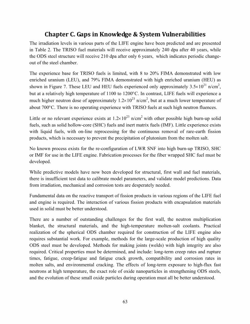
63
Chapter C. Gaps in Knowledge & System Vulnerabilities The irradiation levels in various parts of the LIFE engine have been predicted and are presented in Table 2. The TRISO fuel materials will receive approximately 240 dpa after 40 years, while the ODS steel structure will receive 210 dpa after only 6 years, which indicates periodic change-out of the steel chamber.
The experience base for TRISO fuels is limited, with 8 to 20% FIMA demonstrated with low enriched uranium (LEU), and 79% FIMA demonstrated with high enriched uranium (HEU) as shown in Figure 7. These LEU and HEU fuels experienced only approximately 3.5×10²¹ n/cm2, but at a relatively high temperature of 1100 to 1200°C. In contrast, LIFE fuels will experience a much higher neutron dose of approximately 1.2×10²³ n/cm2, but at a much lower temperature of about 700°C. There is no operating experience with TRISO fuels at such high neutron fluences.
Little or no relevant experience exists at 1.2×10²³ n/cm2 with other possible high burn-up solid fuels, such as solid hollow-core (SHC) fuels and inert matrix fuels (IMF). Little experience exists with liquid fuels, with on-line reprocessing for the continuous removal of rare-earth fission products, which is necessary to prevent the precipitation of plutonium from the molten salt.
No known process exists for the re-configuration of LWR SNF into high burn-up TRISO, SHC or IMF for use in the LIFE engine. Fabrication processes for the fiber wrapped SHC fuel must be developed.
While predictive models have now been developed for structural, first wall and fuel materials, there is insufficient test data to calibrate model parameters, and validate model predictions. Data from irradiation, mechanical and corrosion tests are desperately needed.
Fundamental data on the reactive transport of fission products in various regions of the LIFE fuel and engine is required. The interaction of various fission products with encapsulation materials used in solid must be better understood.
There are a number of outstanding challenges for the first wall, the neutron multiplication blanket, the structural materials, and the high-temperature molten-salt coolants. Practical realization of the spherical ODS chamber required for construction of the LIFE engine also requires substantial work. For example, methods for the large-scale production of high quality ODS steel must be developed. Methods for making joints (welds) with high integrity are also required. Critical properties must be determined, and include: long-term creep rates and rupture times, fatigue, creep-fatigue and fatigue crack growth, compatibility and corrosion rates in molten salts, and environmental cracking. The effects of long-term exposure to high-flux fast neutrons at high temperature, the exact role of oxide nanoparticles in strengthening ODS steels, and the evolution of these small oxide particles during operation must all be better understood.

64
Chapter D. Strategy for Future Work Over the next twelve months, the LIFE Materials Team will deliver more detailed predictive models for structural and first wall materials, as well as for solid and liquid fuels, a detailed plan for experiments necessary to calibrate and validate model parameters, and preliminary results from the initial materials performance experiments, assuming that adequate resources are available for the planned work scope. Specific issues that must be dealt with include: stresses associated with the accumulation of fission gases within the particles of fuel surrounding the fusion target area; pulsed heating of the fuel and first wall, and the associated mechanical stresses; high-temperature creep of structural materials; corrosion and environmental cracking of those reactor components exposed to the high-temperature molten-salt coolant and tritium breeding blanket; radiation damage on fuels, structural and first wall materials; the creation of appropriate test environments for materials within the laboratory, including extreme neutron fluxes with representative energy spectra, rapid thermal pulsing with homogeneous heating; exposures to high-temperature lithium-beryllium-fluoride molten salts, and special problems associated with the use of beryllium multipliers in such applications. Planning, modeling and early experimental work will be used to begin solving materials problems currently believed to challenge the LIFE reactor concept. A detailed research and development strategy will be formulated, thereby enabling the team to attack crucial materials problems in an efficient and comprehensive manner. The initial fabrication of prototypical fuels by an experienced industrial partner will be initiated, incorporating those design changes necessary to allow the fuels to survive higher burn-up and neutron dose. The proposed developmental work will leverage the extensive knowledge base within the Department of Energy that is now being Advanced Gas Reactor (AGR), and will provide impetus for creating fuels capable of even higher burn-up, and capable of accommodating a much broader range of uranium feeds.
This section of the Topical Report (TR) describes work that will be done to address the materials challenges that have been identified and discussed. Materials research and development activities will focus on: fuel design, fabrication, and performance; and structural and first wall and structural materials options, fabrication and performance; specialty materials for the balance of plant; materials availability and cost; and issues pertaining to the end of the fuel cycle, including proliferation resistance, interim storage, and geological disposal of the residual waste.
A systematic approach to materials modeling will enable design of next-generation materials, as illustrated in Figure 65. Accelerated testing of materials will be required, including irradiations in a new three-beam accelerator facility at LLNL, as illustrated in Figure 66.

65
Fuel Development
Objectives – Fuels
The primary objective of this portion of the proposed work is to develop detailed understanding, the research and development plans for future work that enables the development of two fuel forms: (1) a pure fissile fuel form that consists primarily of U-235 or Pu-239; and (2) a fertile fuel form that consists primarily of U-238.
Three primary fuel sources are envisioned for the LIFE engine: natural uranium, and depleted uranium, and spent nuclear fuel (SNF) from light water reactors (LWR). LIFE technology is unique in that it will enable natural and depleted uranium fuels to be completely burned to fission products, without the need for either chemical processing or enrichment.
Initially, three solid fuels and associated fabrication processes will be evaluated: TRISO (TRI-structural ISO-tropic), SHC (solid hollow core), and IMF (inert matrix fuel), all with protective cladding. The relatively well-developed TRISO process is being favored at the present time as the baseline for the production of fuels capable of surviving high burn-up and high neutron dose. A liquid fuel that is completely immune to radiation damage can be formed by dissolving fertile of fissile materials into molten fluoride salts, and will be developed in parallel. The existence of several parallel paths for system development provides substantial “up-side” potential, and promises to make the proposed development very robust.
Ongoing work at BWXT, INEEL and elsewhere will be leveraged. LLNL will partner with Idaho National Laboratory on the development of their comprehensive integrated TRISO modeling code PARFUME with a goal of expanding its capabilities to include fatigue and thermal shock effects that fuel particles will experience in the LIFE engine. An experimental plan will be developed for employing slabs of TRISO component materials to study bond strength and cracking issues. In addition, a plan will also be composed to use NIF ignition neutrons to validate aspects of PARFUME’s predictions for actual LIFE candidate fuel particles. Work will be initiated with BWXT to develop fuels that can survive conditions even more severe than those encountered in the INL NPR (New Production Reactor).

66
Tasks – Fuels
1) Collect published reports and articles on materials required for solid fuel fabrication, including but not limited to: fertile and fissile materials, in both metallic and ceramic forms; silicon carbide; zirconium carbide; carbons and graphite; and graphite fibers with refractory coatings such as silicon carbide; and molten-salt resistant cladding materials a) Establish database from published data b) Use PARFUME code to predict TRISO performance c) Obtain other established models to predict fuel performance
2) Develop detailed models for high burn-up solid fuels (TRISO, SHC & IMF) accounting for:
a) Stresses due to fission gas accumulation and thermal pulsing b) Transmutation and the effects of such compositional change on properties c) Irradiation-induced structural damage on fuel performance d) Chemical reactivity of materials with high-temperature molten salts
3) Apply those models/codes to predict the failure mechanism of solid fuels under assumed
conditions representative of the conceptual LIFE engine a) Weapons-Grade Plutonium (WG Pu) b) High Enriched Uranium (HEU) c) Natural and Depleted U (DU)
4) Identify predictive modeling needs
a) Specific data required as inputs to codes b) Advanced physics methodologies for predicting the evolution of materials under extreme
environments, and over prolonged periods of time, accounting for the stochastic-nature of the problem, and leveraging advances in supercomputing
5) Radiation effects studies for solid fuel materials
a) Initial accelerated testing with triple-beam accelerator b) High-fluence neutron effects in reactor c) High-fluence neutron effects LIFE demonstration unit d) Determine the feasibility of performing neutron irradiations at external facilities
6) Fabrication of advanced prototypical fuels for testing
a) Enhanced TRISO fuels in collaboration with BWXT, ORNL and INL b) New SHC fuels in collaboration with additional partners experience in composites c) Inert Matrix Fuels in Collaboration with CEA
7) Develop thermochemical model of liquid fuel a) Predict the solubilities of uranium and plutonium b) Predict the solubilities of rare-earth (RE) and noble-metal (NM) fission products
8) Develop an on-line process for continuous removal of RE and NM fission products 9) Testing of high burn-up solid and liquid fuels in LIFE demonstration unit

67
Deliverables – Fuels
1) Comprehensive suite of models for prediction of anticipated failure modes in solid fuels 2) Calibrated model parameters for the various models 3) Documented model validation with existing experimental database 4) Predicted time-dependent temperature distribution in solid fuels 5) Predicted lifetime of solid fuel designs under expected LIFE conditions 6) Sensitivity analysis determining the relative effects of temperature, radiation, fission gas
buildup, and molten-salt corrosion on fuel lifetime of solid fuels 7) Assessment of solid fuel designs with determination of their relative abilities to reach
extended burn-ups and withstand high damage-rates, as well as helium and hydrogen production in LIFE operating conditions
8) Identification of suitable liquid fuel compositions to meet LIFE missions 9) Conceptual design for continuous on-line process for removal of RE/NM fission products 10) Documentation of the irradiation testing strategy for prototype fuel particles that will be used
in FY09 and beyond, including a detailed program to integrate multiple pre-exiting particle accelerators to simultaneously damage materials and implant species such as helium.

68
Structural and First Wall Materials
Objectives
The LIFE Engine requires materials that can withstand harsh conditions of radiaiton, high temperature, active chemical agents, and pulsed (20/s thermal and mechanical stress for periods of time as long as 60 years. While we have identified materials and materials systems candidates for first wall and fuel, practical experience and modeling code validation regarding these materials under the extreme conditions of LIFE does not yet exist. Even if an appropriate neutron material testing facility were to exist, testing materials over the intervals of 60 years will never be a viable option. Accelerated testing methods coupled to advanced theory and modeling is the only way to rapidly evaluate candidate materials. Thus, development of capabilities for reliable accelerated material testing becomes a critical priority for the development of LIFE.
As part of the point design effort we will develop detailed plans for a multi-ion-beam accelerated materials radiation facility while carrying out early experimental simulations of reactor environment radiations by sequential materials irradiations with helium and heavy ions to simulate the materials property changes associated with the LIFE environment. Four key materials will be studied: tungsten, which will be used to fabricate the solid first wall; oxide dispersion strengthened ferritic steel, the structural material for engine construction; beryllium, the proposed neutron multiplier; and graphite, the proposed as a reflector in the baseline engine design. The ODS steel will be studied to radiation damage levels in excess of 200 dpa. Silicon carbide will be studied at radiation damage levels representative of pure fissile and pure fertile fuels. Temperatures for these irradiations will be representative of the anticipated operating temperatures for LIFE.
Integral with this experimental simulation will be the implementation of existing and the development of advanced modeling codes to interpret the experimental data. More importantly the successful implementation of the modeling codes will also serve as a confidence builder for prediction of material performance under LIFE conditions.
The degradation and failure of LIFE Engine components will be limited by high-temperature corrosion in Li2BeF4, LiNaBeF4 and other coolants. A testing program will be needed to understand the corrosion, environmental fracture, thermally-driven fatigue, and radiation damage of hybrid reactor materials in high-temperature molten salts with high neutron fluence. Corrosion and environmental cracking will be exacerbated by thermal aging and radiation damage of crystalline solids, and the formation of transmutation products such as tritium fluoride and related chemical species (TF, DF & HF). Galvanic coupling of dissimilar materials, with one serving as a catalytic cathode, will drive anodic dissolution of the other at an accelerated rate. Enhanced mass transport in the intense flow-field of the vortex and annuli will accelerate corrosive dissolution of materials.
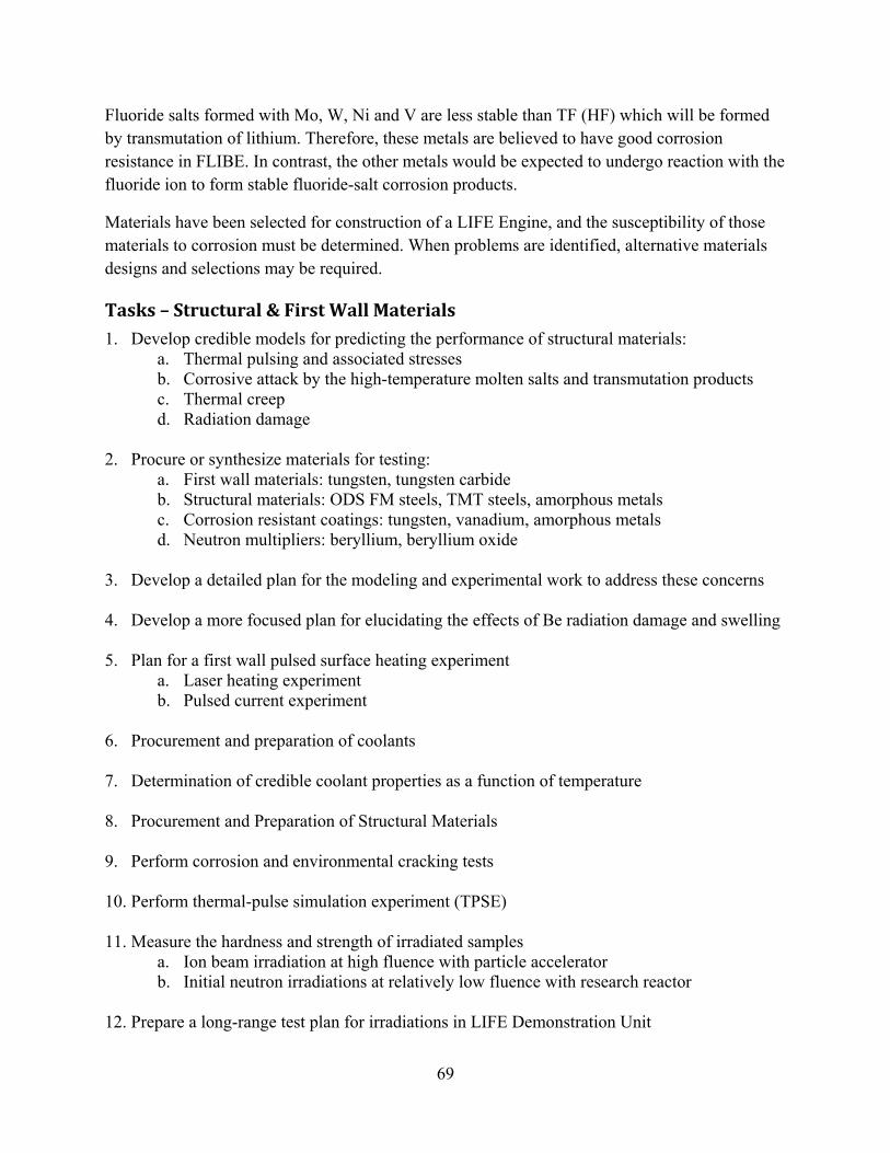
69
Fluoride salts formed with Mo, W, Ni and V are less stable than TF (HF) which will be formed by transmutation of lithium. Therefore, these metals are believed to have good corrosion resistance in FLIBE. In contrast, the other metals would be expected to undergo reaction with the fluoride ion to form stable fluoride-salt corrosion products.
Materials have been selected for construction of a LIFE Engine, and the susceptibility of those materials to corrosion must be determined. When problems are identified, alternative materials designs and selections may be required.
Tasks – Structural & First Wall Materials
1. Develop credible models for predicting the performance of structural materials: a. Thermal pulsing and associated stresses b. Corrosive attack by the high-temperature molten salts and transmutation products c. Thermal creep d. Radiation damage
2. Procure or synthesize materials for testing:
a. First wall materials: tungsten, tungsten carbide b. Structural materials: ODS FM steels, TMT steels, amorphous metals c. Corrosion resistant coatings: tungsten, vanadium, amorphous metals d. Neutron multipliers: beryllium, beryllium oxide
3. Develop a detailed plan for the modeling and experimental work to address these concerns 4. Develop a more focused plan for elucidating the effects of Be radiation damage and swelling 5. Plan for a first wall pulsed surface heating experiment
a. Laser heating experiment b. Pulsed current experiment
6. Procurement and preparation of coolants 7. Determination of credible coolant properties as a function of temperature 8. Procurement and Preparation of Structural Materials 9. Perform corrosion and environmental cracking tests 10. Perform thermal-pulse simulation experiment (TPSE) 11. Measure the hardness and strength of irradiated samples
a. Ion beam irradiation at high fluence with particle accelerator b. Initial neutron irradiations at relatively low fluence with research reactor
12. Prepare a long-range test plan for irradiations in LIFE Demonstration Unit

70
Deliverables – Structural & First Wall Materials
1. Necessary database to support to support development of conceptual and predictive models
a. Thermal pulse model b. Corrosive model c. Thermal creep model d. Radiation damage model
2. Credible conceptual mechanistic model for:
a. Thermal pulsing and associated stresses b. Corrosive attack by molten salts c. Thermal creep d. Radiation damage
3. Quantitative predictive model for:
a. Thermal pulsing and associated stresses b. Corrosive attack by molten salts c. Thermal creep d. Radiation damage
4. Library of calibrated model parameters:
a. Thermal pulse model b. Corrosive model c. Thermal creep model d. Radiation damage model
5. Quantitative assessment of the performance and life time of structural and first-wall materials 6. High quality material samples for testing:
a. First wall materials: tungsten, tungsten carbide b. Structural materials: ODS FM steels, TMT steels, amorphous metals c. Corrosion resistant coatings: tungsten, vanadium, amorphous metals d. Neutron multipliers: beryllium, beryllium oxide
7. Data for further calibration and validation of models
a. Pulsed heating experiment with laser b. Pulsed heating experiment with current c. Coolant properties as function of temperature d. Corrosion rates as function of temperature and radiation damage e. Hardness, strength and creep as function of temperature and radiation damage f. Ion beam irradiation at high fluence with particle accelerator g. Initial neutron irradiations at relatively low fluence with research reactor
8. Long-range test plan for irradiations in LIFE Demonstration Unit

71
Summary The LIFE Engine is an advanced high-performance nuclear energy conversion device with an ICF spark plug and requires integration of some of the world’s most advanced reactor materials. The initial engine concept includes a W 1st wall, ODS steel structure, Be neutron multiplier blanket, TRISO fission blanket, and molten salt coolant.
There are three primary missions for the LIFE engine, which include the burning of excess weapons-grade plutonium (WG-Pu), natural and depleted uranium (DU and HEU), and light-water reactor (LWR) spent nuclear fuel (SNF). Materials in the LIFE Engine will be subjected to a severe radiation and high temperature environment. Such operating conditions will challenge current materials and stimulate development of next-generation materials. The LIFE engine’s structural challenges include: need for high-temperature strength; resistance to high-temperature creep; immunity to radiation damage, including swelling and helium embrittlement; resistance to corrosion and environmental cracking in high-temperature molten fluoride salts; and the ability to be fabricated into necessary shapes and configurations with practical welding processes. It is hoped that these challenges can be met with oxide dispersion strengthened (ODS) ferritic steels, sheets and coatings of refractory metals such as tungsten, advanced solid or liquid fuels, and other advanced reactor materials.
The design of LIFE engines capable of meeting the identified missions will require data and models that account for the corrosion and environmental cracking of as-received and irradiated structural and cladding materials in high-temperature molten salt coolants and liquid fuels.
This Topical Report is Volume 1 in a 12-volume series which is summarized below, and discusses data and models pertinent to the performance of materials in LIFE engine applications found in Volumes 2 through 9. It also discusses current understanding of issues related to proliferation resistance, repository requirements, and licensibility found in Volumes 10, 11 and 12, respectively.
Acknowledgements
Financial Support George Miller, Director, Lawrence Livermore National Laboratory
Visionary Leadership Edward Moses, Principal Associate Director, National Ignition Facility & Photon Sciences
Tomas Diaz de la Rubia, Principal Associate Director, Science and Technology

72
Bibliography
T. R. Allen, J. Gan, J. I. Cole, S. Ukai, S. Shutthanandan and S. Thevuthasan: The stability of 9Cr-ODS oxide particles under heavy-ion irradiation, Nuclear Science & Engineering 151 (2005) 305–312.
P. L. Andresen, F. P. Ford: Intl. Journal of Pressure Vessels and Piping, 59 (1994) 61-70.
P. L. Anderson: Modeling of water and material chemistry effects on crack tip chemistry and resulting crack growth kinetics, 3rd International Conference, Degradation of Materials in Nuclear Power Industry, Traverse City, MI, August 31st through September 4th 1987 (General Electric Corporate Research Center, Schenectady, NY, 1987).
P. L. Andresen, F. P. Ford: Modeling of irradiation effects on stress corrosion crack growth rates, Presented at International Cooperative Group on Irradiation Assisted Stress Corrosion Cracking, 1988 Summer Meeting, Abisko, Sweden, June 7th through 8th 1988 (General Electric Corporate Research Center, Schenectady, NY, 1988).
T. Angeliu, J. Ward and J. Witter: Assessing the effects of radiation damage on Ni-base alloys for the Prometheus space reactor system (LM-06K033, April 4th 2007, Knolls Atomic Power Laboratory, KAPL, Lockheed Martin, P. O. Box 1072, Schenectady, NY 12301-1072, Telephone 518-395-6163, Email [email protected]).
ASTM G 5-94: Standard reference test method for making potentiostatic and potentiodynamic anodic polarization measurements. Designation G 5-94, In 1997 Annual Book of American Society for Testing and Materials Standards, Section 3, Vol. 3.02 (ASTM, 1997), pp. 54–57.
ASTM G 5-87: Standard reference test method for making potentiostatic and potentiodynamic anodic polarization measurements. Designation G 5-87, In 1989 Annual Book of American Society for Testing and Materials Standards, Section 3, Vol. 3.02 (ASTM, 1989), pp. 79–85. ASTM G 3-89: Standard practice for conventions applicable to electrochemical measurements in corrosion testing. Designation G 3-89, In 1997 Annual Book of American Society for Testing and Materials Standards, Section 3, Vol. 3.02, (ASTM, 1997), pp. 36–44. ASTM G 61-86: Standard test method for conducting cyclic potentiodynamic polarization measurements for localized corrosion susceptibility of iron-, nickel-, or cobalt-based alloys. Designation G 61-86, In 1997 Annual Book of American Society for Testing and Materials Standards, Section 3, Vol. 3.02 (ASTM, 1997), pp. 231–235. A. J. Bard, L. R. Faulkner: Chapter 2, Potentials and Thermodynamics of Cells; Chapter 3, Kinetics of Electrode Reactions; Chapter 4, Mass Transfer by Migration and Electromigration; Chapter 8, Methods Involving Forced Convection Hydrodynamic Methods, Section 8.3, Rotating Disk Electrode; Chapter 9, Techniques Based on Concepts of Impedance, Electrochemical

73
Methods; Electrochemical Methods, Fundamentals and Applications (John Wiley & Sons, New York, NY, 1980) pp. 44-85; 86-135; 28-315; 316-369.
C. O. Bennet, J. E. Myers: Chapter 14, Some Design Equations for the Flow of Incompressible Fluids; Chapter 25, Boiling and Condensation, Heat & Mass Transfer, 2nd Ed. (McGraw-Hill, 1974) pp. 193-217; 400-417.
E. T. Cheng, B. J. Merril and Dai-Kai Sze: Nuclear aspects of molten salt blankets, Fusion Engineering and Design, Fusion Engineering and Design 69 (2003) 205-213.
J. R. Davis, Ferritic Steels, Guide to Materials Selection, ASM Engineered Materials Handbook, M. M. Gauthier, Volume Chair (American Society of Metals International, Materials Park, OH, 1995) 116-117.
M. A. DeLuchi: Hydrogen vehicles: an evaluation of fuel storage, performance, safety, environmental impacts, and cost, International Journal of Hydrogen Energy 14, 2 (1989) 81-130.
K. F. Farrell and E. H. Lee: Ion damage in a Fe-10Cr-6Mo-0.5Nb ferritic steel, Radiation-Induced Changes in Microstructure, 13th International Symposium, Part I, Garner, Packan, Kumar, Editors, ASTM STP 955 (American Society for Testing and Materials, ASTM, Philadelphia, PA, 1986) pp. 498-519.
A. Caro: Chemistry, Materials and Life Sciences Directorate, Lawrence Livermore National Laboratory, 7000 East Avenue, Livermore, California 94551, Telephone 925-422-1711, Email [email protected].
P. Damange, J. Marian and M. Serrano de Caro: LLNL, 2008.
M. A. DeLuchi: Hydrogen vehicles: an evaluation of fuel storage, performance, safety, environmental impacts, and cost, International Journal of Hydrogen Energy 14, 2 (1989) 81-130.
J. C. Farmer et al.: Corrosion resistance of amorphous Fe49.7Cr17.7Mn1.9Mo7.4W1.6B15.2C3.8Si2.4 coating, a new criticality control material, Journal of Nuclear Technology 161, 2 (2008) 169-189.
J. C. Farmer et al.: Corrosion resistance of thermally sprayed high-boron iron-based amorphous-metal coatings: Fe49.7Cr17.7Mn1.9Mo7.4W1.6B15.2C3.8Si2.4, Journal of Materials Research 22, 8 (2007) 2297-2311.
J. Farmer, S. Lu, D. McCright, G. Gdowski, F. Wang, T. Summers, P. Bedrossian, J. Horn, T. Lian, J. Estill, A. Lingenfelter, W. Halsey: General and localized corrosion of high-level waste container in Yucca Mountain, The 2000 ASME Pressure Vessel and Piping Conference, Seattle, Washington, July 23-27, 2000, Transportation, Storage, and Disposal of Radioactive Materials, PVP Vol. 408 (2000) 53-70.
J. Farmer, S. Lu, T. Summers, D. McCright, A. Lingenfelter, F. Wang, J. Estill, L. Hackel, H-L. Chen, G. Gordon, V. Pasupathi, P. Andresen, S. Tang, M. Herrera: Modeling and mitigation of

74
stress corrosion cracking in closure welds of high-level waste containers for Yucca Mountain, The 2000 ASME Pressure Vessel and Piping Conference, Seattle, Washington, July 23-27, 2000, Transportation, Storage, and Disposal of Radioactive Materials, PVP Vol. 408 (2000) 71-81.
J. C. Farmer, R. D. McCright: Crevice corrosion and pitting of high-level waste containers: integration of deterministic and probabilistic models, Paper No. 98160, Symposium 98-T-2A, Corrosion 98, San Diego, CA March 22-27, 1998 (National Association of Corrosion Engineers, Houston, Texas, 1998). J. C. Farmer, F. T. Wang, R. A. Hawley-Fedder, P. R. Lewis, L. J. Summers, L. Foils: Electrochemical treatment of mixed and hazardous wastes, oxidation of ethylene glycol and benzene by silver (II), Journal of the Electrochemical Society 139, 3 (1992) 654-662. J. C. Farmer, F. T. Wang, P. R. Lewis, L. J. Summers: Destruction of chlorinated organics by cobalt (III) mediated electrochemical oxidation, Journal of the Electrochemical Society, 139, 11 (1992) 3025-3029. J. C. Farmer, F. T. Wang, P. R. Lewis, L. J. Summers, Electrochemical treatment of mixed and hazardous wastes: oxidation of ethylene glycol by cobalt (III) and iron (III), Transactions of the Institute of Chemical Engineering 70 B (1992) 158-164. J. C. Farmer, G. E. Gdowski, R. D. McCright, H. S. Ahluwalia: Corrosion models for performance assessment of high-level radioactive waste containers, Nuclear Engineering Design, 129 (1991) 57-88.
J. C. Farmer, R. D. McCright: A review of models relevant to the prediction of performance of high-level radioactive waste disposal containers, Corrosion 89, April 17-21, 1989, New Orleans, LA (National Association of Corrosion Engineers, Houston, Texas, 1989). J. C. Farmer: Underpotential deposition of copper on gold and the effects of thiourea studied by AC impedance 132, 11 (1985) 2640-2648. F. P. Ford: Current understanding of the mechanisms of stress corrosion and corrosion fatigue, Symposium on Environment-Sensitive Fracture, Evaluation and Comparison of Test Methods, Gaithersburg, MD, April 25th through 28th 1982, ASTM Special Technical Publication 821, ASTM Publication Code Number (PCN) 04-82100-27, S. W. Dean, E. N. Pugh, G. M. Ugiansky, Editors (American Society of Testing and Materials, Philadelphia, PA, 1983) pp. 32-51.
A. R. Foster, R. L. Wright, Jr.: Chapter 4, Nuclear Reactions, Fusion, Chapter 11, Radiation Damage and Reactor Materials, Dispersion-Type Alloys (TRISO), Chapter 13, Nuclear Reactors, Molten Salt Breeder Reactor, Fusion by Laser, Fusion-Fission Symbiosis, Table 13.6, Typical MSBR Compositions and Properties, Figure 13.31, MSBR Fuel Processing Flow Diagram, Basic Nuclear Engineering, 2nd Ed. (Allyn and Bacon, Incorporated, Boston, MA, 1973) pp. 72-80, 330-342, 416-422, 446-449.

75
K. Fukuda, W. Danker, J. S. Lee, A. Bonne, M. J. Crijns: IAEA Overview of Global Spent Fuel Storage, IAEA-CN-102/60 (Department of Energy, International Atomic Energy Agency, Vienna, Austria, 2007) Table I.
W. R. Grimes, S. Cantor: Molten salt as blanket fluids in controlled fusion reactors, The Chemistry of Fusion Technology, Plenum Press, 1972.
C. R. Hammond: The Elements, Nomenclature of Inorganic Chemistry, Physical Constants of Inorganic Compounds, Chemical Rubber Company (CRC) Handbook of Chemistry and Pysics, 61st Ed. (R. C. Weast, M. J. Astle, Editors, CRC Press Incorporated, Boca Raton, FL 33431, 1980) B-2 through B166.
J. I. Han and J. -Y. Lee: Hydriding kinetics of LaNi5 and LaNi4.7Al0.3, International Journal of Hydrogen Energy 14, 3 (1989) 181-186.
P. N. Haubenreich, J. R. Engel: Experience with the molten-salt reactor experiment, Nuclear Applications and Technology 8 (1970) 118-121.
J. E. Indacochea, J. L. Smith, K. R. Litko and E. J. Karell: Corrosion performance of ferrous and refractory metals in molten salts under reducing conditions, Journal of Materials Research 14, 5 (1999) 1990-1995.
R. H. Jones: Stress corrosion cracking, ASM Metals Handbook, 9th Ed. Vol. 13 (ASM, Metals Park, OH, 1987) p. 160.
R. L. Klueh, N. Hashimoto and P. J. Maziasz: New nano-particle-strengthened ferritic-martensitic steels by conventional thermo-mechanical treatment, Journal of Nuclear Materials 367-370 (2007) 48-53.
G. Y. Lai: Molten Salt Corrosion, Chapter 9, Corrosion in Molten Fluorides, Section 9.6, High-Temperature Corrosion of Engineering Alloys, (American Society of Metals International, Materials Park, OH, 1990) pp. 179-180.
R. J. Lauf, T. B. Lindemer and R. L. Pearson: Out-of-reactor studies of fission-product/silicon-carbide interactions in HTGR fuel particles, Journal of Nuclear Materials 120 (1984) 6-30.
M. J. Lubin and A. P. Fraas: Fusion by laser, Scientific American, 225, 6 (1971).
B. J. Makenas, R. G. Trenchard, S. L. Hecht, J. M. McCarthy and F. A. Garner: The effect of swelling in Inconel 600 on the performance of FFTF reflector assemblies, Radiation-Induced Changes in Microstructure, 13th International Symposium, Part I, Garner, Packan, Kumar, Editors, ASTM STP 955 (American Society for Testing and Materials, ASTM, Philadelphia, Pennsylvania, 1986) pp. 206-229.
Mansur and Lee: Journal of Nuclear Materials 179-181 (1991) 105.

76
R. W. Moir, J. D. Lee, F. J. Fulton, F. Huegel, WS. S. Neef, Jr., A. E. Sherwood, P. H. Berwald, R. H. Whitley, C. D. C. Wong, J. H. DeVan, W. R. Grimes, S. K. Ghose: Design of a Helium-Cooled Molten-Salt Fusion Breeder, Fusion Technology 8 (1985) 465-473.
T. Nakayama, M. Takano: Application of slip-dissolution-repassivation model for stress corrosion cracking of AISI 304 stainless steel in boiling 42% MgCl2 solution, Corrosion 42, 1 (1986) 10-14.
Nuclear Energy Agency: Advanced Nuclear Fuel Cycles and Radioactive Waste Management, NEA No. 5990 (Nuclear Energy Agency, Organization for Economic Co-Operation and Development, 2006) p. 30, Table 2.2.
Nuclear Waste News: “DOE Testifies, Yucca's Costs Doubled, New Estimates of More Than $90 Billion”, Nuclear Waste News, Capitol Press LLC, Vol. 28, No. 15, July 21, 2008, p. 1.
J. S. Newman: Chapter 16, Fundamental Equations; Chapter 17, Convective Transport Problems, Section 103, Rotating Disk, Section 105, Annulus, Section 109, Rotating Cylinder, Electrochemical Systems, 2nd Ed. (Prentice Hall, Englewood Cliffs, NJ, 1991), pp. 301-304; 305-339.
H. Nishimura, A. Suzuki, T. Terai, M. Yamawaki, S. Tanaka, A. Sagra and O. Motojima: Chemical behavior of Li2BeF4 molten salt as a liquid tritium breeder, Fusion Engineering and Design 58-59 (2001) 667-672.
J. A. Ober: Lithium, 2006 Minerals Yearbook; Mineral Commodity Summaries (USGS, October 2007, Tel 703-648-7717, Email [email protected]).
D. O’Donnel: Joining of Oxide Dispersion Strengthened Materials, Special Welding and Joining Topics, (Complete Reference Required) pp. 1037-1040.
H. Okamoto: Desk Handbook of Phase Diagrams for Binary Diagrams (American Society of Metals, International, Materials Park, Ohio, 2000).
A. Paskin, K. Sieradzki, D. K. Som, G. J. Dienes: Dislocation enhancement and inhibition induced by films on crack surfaces, Acta Metall. 31, 8 (1983) 1253-1265.
A. Paskin, K. Sieradzki, D. K. Som, G. J. Dienes: Environmentally induced crack nucleation and brittle fracture, Acta Metall. 30 (1982) 1781-1788.
A. Paskin, K. Sieradzki, D. K. Som, G. J. Dienes: Computer simulation of crack propagation, Phys. Rev. Lett. 44 (1980) 940-943.
L. Pauling: Chapter 15, Oxidation-Reduction Reactions, Electrolysis, General Chemistry (Dover Publications, New York, NY, 1947, 1950, 1970) pp. 513-550.
77
D. Petti, P. Martin, M. Phélip and R. Ballinger: Development of improved models and designs for coated-particle gas reactor fuels (Final Report, International Nuclear Energy Research Initiative (INEEL/EXT-05-02615, Idaho National Engineering and Environmental Laboratory, Idaho Falls, Idaho 83415, December 2004).
D. A. Petti, G. R. Smolik, M. F. Simpson, J. P. Sharpe, R. A. Andrerl, S. Fukada, Y. Hatano, M. Hara, Y. Oya, T. Terai, D-K. Sze, S. Tanaka: Jupiter-II molten salt FLIBE research, an update on trituium, mobilization and redox chemistry experiments, Fusion Engineering and Design 81 (2006) 1439-1449.
B. A. Pint, P. F. Tortorelli, A. Jankowski, J. Hayes, T. Muroga, A. Suzuki, O. I. Yeliseyeva, V. M. Chernov: Recent progress in the development of electrically insulating coatings for a liquid lithium blanket, Journal of Nuclear Materials 329-333 (2004) 119-124.
B. A. Pint, J. L. Moser and P. F. Tortorelli: Liquid metal compatibility issues for test blanket modules, Fusion Engineering and Design 81 (2006) 901-908.
M. W. Rosenthal, P. R. Kasten, R. B. Briggs: Nuclear Technology 8, 2 (1970) 111.
A. I. Ryazanov, A. V. Klaptsov, A. Kohyama and H. Kishimoto: Radiation swelling of SiC under neutron irradiation, Journal of Nuclear Materials 307-311 (2002) 1107-1111.
R. Schaublin et al.: Microstructural development under irradiation in European ODS FM steels, Journal of Nuclear Materials 351 (2006) 247-260.
K. B. Shedd, Beryllium, 2006 Minerals Yearbook; Mineral Commodity Summaries (USGS, October 2007, Tel 703-648-4974, Email [email protected]).
L. Smart and E. Moore: Solid State Chemistry, An Introduction, 2nd Ed. (Chapman and Hall, London, UK, 1992, 1996; Reprinted by Stanley Thornes Publishers Ltd., Ellenborough House, Wellington Street, Cheltenham GL50 1YW, UK) 379.
D. L. Smith, M. C. Billone, K. Natesan: Vanadium-base alloys for fusion first-wall/blanket applications, International Journal of Refractory Metals and Hard Materials 18 (2000) 213-224.
L. L. Snead, T. Nozawa, Y. Katoh, T-S. Byun, S. Kondo and D. A. Petti: Handbook of SiC properties on fuel performance modeling, Journal of Nuclear Materials 371 (2007) 329-377.
A. Suzuki, T. Muroga, B. A. Pint, T. Yoneoka and S. Tanaka: Corrosion behavior of AlN for self-cooled Li/V blanket application, Fusion Engineering and Design 69 (2003) 397-401.
I. N. Sviatoslavsky, M. E. Sawan, E. A. Mogahed, S. Majumdar, R. Mattas, S. Malang, P. J. Fogarty, M. Friend, C. P. C. Wong and S. Sharafat: Engineering and geometric aspects of the solid wall re-circulating fluid blanket based on advanced ferritic steel, Fusion Engineering and Design 72 (2004) 307-326.

78
L. Theodore: Energy transport, Example 4.6.2, Long hollow cylinder, Example 4.6.3, Solid cylinder with uniform heat generation rate, Transport Phenomena for Engineers (International Textbook Company, London, UK, 1971) pp. 157-161.
P. A. Thornton and V. J. Colangelo: Chapter 9, Fracture Toughness of Engineering Materials, Fundamentals of Engineering Materials (Prentice-Hall Incorporated, Englewood Cliffs, NJ, 1985) pp. 262-325.
R. Treseder, R. Baboian, and C. Munger: Polarization resistance method for determining corrosion rates, Corrosion Engineer’s Reference Book, 2nd Ed. (National Association of Corrosion Engineers, NACE, Houston, Texas, 1991) pp. 65-66.
D. F. Williams, L. M. Toth and K. T. Clarno: Assessment of candidate molten salt coolants for the advanced high-temperature reactor (ORNL/TM-2006/12, Nuclear Science and Technology Division, Oak Ridge National Laboratory, P.O. Box 2008, Oak Ridge, Tennessee 37831-6283, March 2006).
I. Wright, B. Pint and Z. Ping Lu: Overview of ODS alloy development (Oak Ridge National Laboratory, 1 Bethel Road, Oak Ridge, TN).
S. Ukai, M. Fujiwara: Perspective of ODS alloys application in nuclear environments, Journal of Nuclear Materials 307-311 (2002) 749-757.
S. Ukai et al.: Oxide dispersion strengthened (ODS) fuel pin fabrication for BOR-60 irradiation test, Journal of Nuclear Science & Technology 42, 1 (2005) 109-122.
S. Ukai and S. Ohtsuka: Low cycle fatigue properties of ODS ferritic-martensitic steels at high temperature, Journal of Nuclear Materials 367-370 (2007) 234-238.
I. Ursu: Chapter 5, Moderator Materials, Chapter 12, Materials in Fusion Reactors, Physics and Technology of Nuclear Materials (Pergamon Press, New York, New York, 1985) pp. 169-206, 406-457.
W. C. Young: Chapter 12, Shells of Revolution; Pressure Vessels; Pipes, Table 32, Spherical Vessel, Case No. 2a, Uniform Internal Pressure, Roark’s Formulas for Stress and Strain, 6th Ed. (McGraw-Hill Incorporated, San Francisco, CA) pp. 515-646.
S. J. Zinkle and N. M. Ghoniem: Operating temperatue windows for fusion reactor structural materials, Fusion Engineering and Design, 51-51 (2000) 55-71.
S. J. Zinkle: Materials in extreme nuclear environments (Invited Presentation, National Ignition Facility, Lawrence Livermore National Laboratory, March 17, 2008).
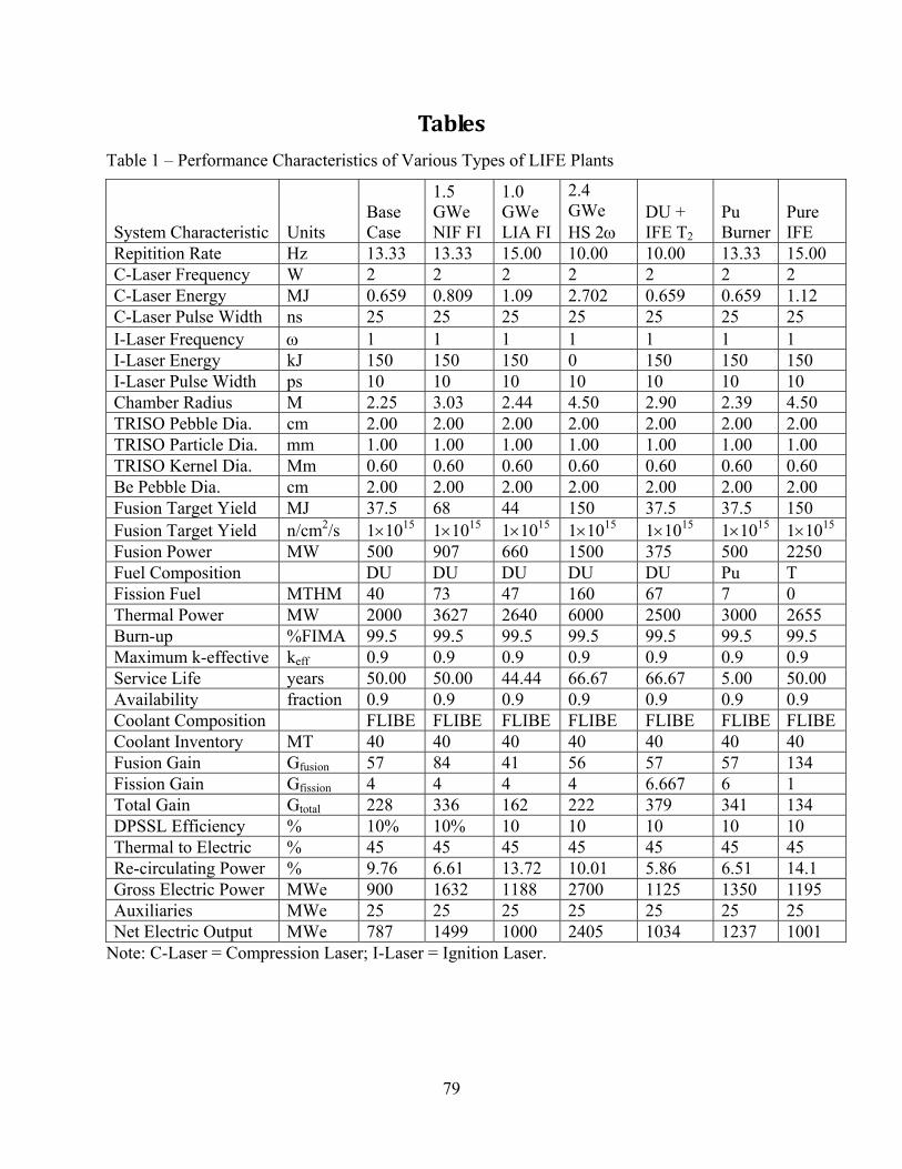
79
Tables
Table 1 – Performance Characteristics of Various Types of LIFE Plants
System Characteristic Units Base Case
1.5 GWe NIF FI
1.0 GWe LIA FI
2.4 GWe HS 2ω
DU + IFE T2
Pu Burner
Pure IFE
Repitition Rate Hz 13.33 13.33 15.00 10.00 10.00 13.33 15.00 C-Laser Frequency W 2 2 2 2 2 2 2 C-Laser Energy MJ 0.659 0.809 1.09 2.702 0.659 0.659 1.12 C-Laser Pulse Width ns 25 25 25 25 25 25 25 I-Laser Frequency ω 1 1 1 1 1 1 1 I-Laser Energy kJ 150 150 150 0 150 150 150 I-Laser Pulse Width ps 10 10 10 10 10 10 10 Chamber Radius M 2.25 3.03 2.44 4.50 2.90 2.39 4.50 TRISO Pebble Dia. cm 2.00 2.00 2.00 2.00 2.00 2.00 2.00 TRISO Particle Dia. mm 1.00 1.00 1.00 1.00 1.00 1.00 1.00 TRISO Kernel Dia. Mm 0.60 0.60 0.60 0.60 0.60 0.60 0.60 Be Pebble Dia. cm 2.00 2.00 2.00 2.00 2.00 2.00 2.00 Fusion Target Yield MJ 37.5 68 44 150 37.5 37.5 150 Fusion Target Yield n/cm2/s 1×10¹⁵ 1×10¹⁵ 1×10¹⁵ 1×10¹⁵ 1×10¹⁵ 1×10¹⁵ 1×10¹⁵ Fusion Power MW 500 907 660 1500 375 500 2250 Fuel Composition DU DU DU DU DU Pu T Fission Fuel MTHM 40 73 47 160 67 7 0 Thermal Power MW 2000 3627 2640 6000 2500 3000 2655 Burn-up %FIMA 99.5 99.5 99.5 99.5 99.5 99.5 99.5 Maximum k-effective keff 0.9 0.9 0.9 0.9 0.9 0.9 0.9 Service Life years 50.00 50.00 44.44 66.67 66.67 5.00 50.00 Availability fraction 0.9 0.9 0.9 0.9 0.9 0.9 0.9 Coolant Composition FLIBE FLIBE FLIBE FLIBE FLIBE FLIBE FLIBE Coolant Inventory MT 40 40 40 40 40 40 40 Fusion Gain Gfusion 57 84 41 56 57 57 134 Fission Gain Gfission 4 4 4 4 6.667 6 1 Total Gain Gtotal 228 336 162 222 379 341 134 DPSSL Efficiency % 10% 10% 10 10 10 10 10 Thermal to Electric % 45 45 45 45 45 45 45 Re-circulating Power % 9.76 6.61 13.72 10.01 5.86 6.51 14.1 Gross Electric Power MWe 900 1632 1188 2700 1125 1350 1195 Auxiliaries MWe 25 25 25 25 25 25 25 Net Electric Output MWe 787 1499 1000 2405 1034 1237 1001
Note: C-Laser = Compression Laser; I-Laser = Ignition Laser.

80
Table 2 – Fluence and Damage Levels in the LIFE Engine Be Blanket
Tungsten ODS Steel Beryllium SiC GraphiteFast Fluence (n/cm2) 2.89E+22 2.89E+22 2.28E+22 7.66E+20 7.66E+20
Total Fluence (n/cm2) 8.00E+22 8.00E+22 7.87E+22 2.97E+21 2.97E+21Damage (dpa) 10 36 13 6 3
He (appm) 10 312 5000 88H (appm) 22 1176 51 139
Temperature (°C) 750-1300 650-750 650-750 750-800 750-800
First Wall TRISO Fuel
Note: The irradiation levels in various parts of the LIFE engine have been predicted and are presented in Table 1. The TRISO fuel materials will receive approximately 240 dpa after 40 years, while the ODS steel structure will receive 210 dpa after only 6 years, which indicates periodic change-out of the steel chamber.
Table 3 – Density and Melting Points of Candidate Fissionable Fuels
Uranium Compound
Density (g/cm3) Melting Point (°C) Analog Structure
UN 14.32 2850 NaCl Cubic
UO2 10.97 2880 CaF2 Cubic
UC2 11.68 2470 Tetragonal
UC 13.63 2370 NaCl Cubic
USi 10.40 1600 Orthorhombic
UAl2 8.10 1590
UAl3 6.70 1320
U 19.13 1133
Th4 6.32 1114
UF4 6.70 1036
UAl4 6.00 730
Note: A wide variety of potential fuel materials exist for solid and liquid fuels. In the case of solid fuels, nitrides, oxides, carbides, silicides, aluminides and metals have all been considered. As shown in Table 2, oxides, nitrides and carbides have the highest melting points. Commercial TRISO fuels use a mixed ceramic phase, uranium oxy-carbide (UOC), which minimized thermal migration effects of the kernel.

81
Table 4 – Challenges Facing TRISO Fuels & Mitigation Strategies
Challenges facing TRISO fuels Design feature meeting the challenge
Irradiation swelling of SiC capsule & PyC layers
The LIFE engine is designed with a lower operating temperature to avoid the non-saturable void-swelling regime
Stress in SiC capsule due to fission gas (Kr & Xe) pressure
The SiC capsule is designed with a thicker wall
Reaction of C & O2 released from UOC to form CO
ZrC is used as a getter is used to capture liberated oxygen
Fuel kernel migration up temperature gradient
UOC is substituted for UO2 in fuel kernel
Fission product (FP) attack of SiC capsule Sacrificial SiC is used close to kernel to form stable 1:3:3:5 U:Pd:Si:C (MP ~ 1952°C) Use of diffusion barrier to FP prevent contact
Note: Several challenges must be met to achieve high burn-up with TRISO-type fuels in the LIFE engines. The challenges that must be met, and known strategies for meeting these challenges are outlined in Table 3.

82
Table 5 – Blanket and Coolant Properties
Salt Formula
Form
ula
Wei
ght
Mel
ting
Poin
t
Late
nt H
eat o
f Fu
sion
Vap
or P
ress
ure
(900
ºC)
Den
sity
Hea
t Cap
acity
(7
00°C
)
Vis
cosi
ty
Ther
mal
C
ondu
ctiv
ity
Neu
tron
Cap
ture
vs
. Gra
phite
Mod
erat
ing
Rat
io
FW MP ∆Hf Pvap ρ ρ × Cp µ Κ (g/mol) (ºC) (cal/g) (mm Hg) (g/cm3) (cal/cm3/ºC) (cP) (W/m-K) Li 6.9 179 554 Be 9.0 1283 1820 Na 23.0 97.81 970 K 39.1 63.65 860 LiF 25.9 842 2300 BeF2 47.0 1086 LiF-BeF2 33.0 460 1.2 1.94 1.12 5.6 1.00 8 60 LiF-NaF-BeF2 38.9 315 1.7 2.00 0.98 5.0 0.97 20 22 KF-ZrF4 103.9 390 2.8 2.80 0.70 5.1 0.45 67 3 Rb-ZrF4 132.9 410 1.3 3.22 0.64 5.1 0.39 14 13 LiF-NaF-ZrF4 84.2 436 5 2 2.79 0.84 6.9 0.53 20 13 LiF-NaF-KF 41.3 454 0.7 2.02 0.91 2.9 0.92 90 2 LiF-NaF-RbF 67.7 435 0.8 2.69 0.63 2.6 0.62 20 8 72LiF-16BeF2-12ThF4 63.00 0.1 torr 3.35 12 1.10 70LiF-12BeF2-18ThF4 3.87 71LiF-2BeF2-27ThF4 54.00 4.52 15-25 0.70

83
Note: A wide variety of high temperature fluids exist that can be used to cool fission, fusion and fusion-fission hybrid systems, and include liquid metals and alloys, and fluoride salts. These include lithium, beryllium, sodium, potassium, alkali metal alloys, lithium fluoride, beryllium fluoride, lithium-beryllium fluoride (FLIBE = Li2BeF4), and mixed alkali-metal fluorides (FLiNaK = Li-Na-K-F). The presence of the lithium in the salt enables breeding of tritium, while the beryllium helps moderate neutrons. At the present time, the LIFE engine design specifies FLIBE for the primary coolant system, with the extraction of breed tritium from this fluid. The secondary cooling loop will use beryllium-free FLiNaK, which is both less expensive and less hazardous than the FLiNaK. The properties of many of these high-temperature heat-transfer fluids are summarized in Table 5 [Williams et al. 2006; Moir et al. 1985; Wright and Foster 1973; Rosenthal et al. 1971].

84
Table 6 – Important Physical Properties of Candidate Structural Materials
Property Type 316L Stainless Steel
Type HT-9 Ferritic Steel
V-Cr-Ti Alloy
Melting Temperature ( °C) 1400 1420 1890
Density (g/cm3) 8.0 7.8 6.1
Poisson’s Ratio 0.27 0.27 0.36
Modulus of Elasticity (GPa at 400°C) 168 180 120
Linear Thermal Expansion (10-6/K)
400°C 17.6 11.8 10.2
500°C 18.0 12.3 10.3
600°C 18.3 12.6 10.5
Thermal Conductivity (W/m-K
400°C 19.5 26.8 33.6
500°C 21.0 27.3 34.5
600°C 22.5 27.7 35.3
Electrical Resistivity (µm)
400°C 1.01 0.91* 0.67
500°C 1.06 0.99* 0.74
600°C 1.12 1.05*
Specific Heat (J/kg-K)
400°C 560 600 535
500°C 575 680 560
600°C 580 800 575

85
Note: A number of steels have been considered for building the structure of the LIFE engine. These include a variety of austenitic stainless steels, ferritic steels, and refractory metal alloys such as V-Cr-Ti, which are all included in Table 4. The austenitic steels are prone to extreme swelling and high temperature thermal creep, as will be discussed subsequently. Ferritic steels show relatively little swelling during neutron irradiation, and can be enhanced by inclusion of a nano-dispersion of oxide particles. The refractory may be useful at higher temperatures than the levels that can be attained with austenitic and ferritic steels. The data for electrical resistance of the ferritic steel is assumed to be equal to that of Type 410 stainless steel (*) [Smith et al. 2000].

86
Table 7 – Nuclear Related Properties of Candidate Structural Materials
Property Type 316L Austenitic Steel
Type HT-9 Ferritic Steel
V-5Cr-5Ti Vanadium Alloy
Silicon Carbide
Melting Temperature ( °C)
1400 1420 1880 2600a
Radiation Damage Rate (dpa)
11 11 11 12
Helium Transmutation Rate (appm)
174 130 57 1500
Hydrogen Transmutation Rate (appm)
602 505 240 560
Nuclear Heating Rate (W/cm3)
11 11 7 11
Note: Austenitic 316L stainless steel, high-strength HT-9 ferritic steel, refractory V-Cr-Ti alloy, and silicon-carbide, all of potential interest for application in the LIFE engine have been irradiated, with values of the radiation damage rate, helium transmutation rate, hydrogen transmutation rate, and nuclear heating rate measured. Irradiations were done with ~14 MeV neutrons at a superficial power density of ~1 MW/m2 for 1 year. These published data are tabulated in Table 5 [Smith et al. 2000].

87
Table 8 – Radiation Swelling of Inconel 600
Material Specimen Fluence (n cm-2) Vol. Change by Immersion (%)
Vol. Change by TEM (%)
Data Source
Inconel 600 1×10²² n cm-2 at E > 0.1 MeV 3.6 % 5.0 % Table 1
Inconel 600 1×10²² n cm-2 at E > 0.1 MeV 0.32% < 0.1% Table 1
Inconel 600 1×10²² n cm-2 at E > 0.1 MeV < 0.5% Fig. 11
Inconel 600 4×10²² n cm-2 at E > 0.1 MeV 1% Fig. 11
Inconel 600 7×10²² n cm-2 at E > 0.1 MeV 2% Fig. 11
Inconel 600 9×10²² n cm-2 at E > 0.1 MeV 5% Fig. 11
Note: Data for the irradiation-induced swelling of Inconel 600, and nickel-based austenitic steel has been published by Makenas et al. more than 20 years ago, as shown in Table 6, and exceeds 5% at 9×10²² n cm-2 and E > 0.1 MeV. Such swelling makes the nickel-based austenitic alloys is believed to make this family of alloys unacceptable for application in the LIFE engine. [Makenas et al. 1986, Table 1, Figure 11].

88
Table 9 – Guidance on Acceptable Compositions for Oxidation-Resistant Refractory Steels
Max. Temp. (°C) Carbon (%) Silicon (%) Chromium (%) Nickel (%)
850 0.35-0.45 2-3 8-10
900 < 0.12 < 0.8 16-18
950 0.25-0.34 2-3 12-14 6-7.5
1000-1050 < 0.2 2-3 19-22 12-15
1100-1150 < 0.15 < 1 27-30
Note: The steels used for construction of the LIFE engine must be able to withstand high temperatures without melting or excessive thermal creep. General guidelines for the compositions of oxidation-resistant refractory steels have been published, as shown in Table 7. At temperatures between 850°C, which are the current upper bounds for the LIFE engine design, an alloy, with recommended concentrations of 0.35 to 0.45% for carbon, 2 to 3% for silicon, and 8 to 10% for chromium. The oxide dispersion strengthened (ODS) ferritic steels that are now being considered for the LIFE engine have comparable levels of chromium.

89
Table 10 – Materials Compatibility with Li2BeF4 Coolant
Alloy Expected Corrosive Attack
V Alloys No – Acceptable
W Alloys No – Acceptable
Mo Alloys No – Acceptable
Austenitic Steel Yes – Manageable with Careful Engineering
Ferritic Steels Yes – Manageable with Careful Engineering
Nb Alloys Yes – Unacceptable
Ta Alloys Yes – Unacceptable
Be Alloys Yes – Requires Mitigation
Graphite Unknown
Note: The corrosive attack of ferritic steels in FLIBE is considered to be manageable, provide that steps are taken to control the dissolution of the chromium into the fluoride salt. Corrosion resistance can be enhanced through careful engineering design, avoiding galvanic coupling of dissimilar metals, unless sacrificial protection is sought. For example, either Li or Be could be used as sacrificial anodes for ferritic steel components. The beryllium neutron multiplier should be protected with a cladding or encapsulation to prevent unacceptable rates of dissolution during the service of the LIFE engine.

90
Table 11– Free Energies of Formation for Various Fluorides
Fluoride Salts: Possible Corrosion Products
Free Energy of Formation (kcal/g-mol F) at 1000K
MoF6 -50.2
WF6 -56.8
NiF2 -55.3
VF5 -58
VF4 -66
HF -66.2
FeF2 -66.5
CrF2 -75.2
BeF2 -106.9
LiF -125.2
Note: The transmutation of lithium in the Li2BeF4 forms corrosive tritium fluoride, which behaves chemically like hydrogen fluoride, or hydrofluoric acid. The ultimate selection of materials for long-term containment such corrosive transmutation products in fluid pumping loops requires the use of alloy systems with constituents that form fluoride salts less thermodynamically stable than hydrogen fluoride. It is therefore useful to rank candidate alloying constituents based upon the free energies of formation of their respective fluoride salts, each with the units of kilocalories per gram mole of fluoride at 1000 Kelvin. Such a ranking reveals that MoF6, WF6, NiF2, VF5, VF4 have lower (negative) free energies than that of HF, indicating acceptability of Mo, W, Ni, and V, while FeF2 has a (negative) free energy comparable to HF, indicating marginal acceptability of Fe-based alloys. Chromium has higher (negative) free energy, which explains the dissolution of chromium by such fluoride salts, and the formation of the well-known chromium depletion layer. Some refractory materials such as Nb-based and Ta-based alloys would be expected to be unacceptable for long-term exposure in high-temperature fluoride salts. Note that metallic beryllium (neutron multiplier in LIFE engine) would be expected to undergo dissolution in Li2BeF4, especially with galvanic coupling to more noble materials such as Mo-, W-, Ni-, V- and Fe-based alloys [Cheng et al. 2003].

91
Table 12 – Corrosion of Steels in High Temperature Molten Salts
Loop
#
Allo
y
Salt
Dur
atio
n (h
ours
)
T max
(ºC
)
Cor
rosi
on D
epth
(m
il)
Cor
rosi
on R
ate
(mil/
yr)
ON
L R
epor
t [R
efer
ence
]
116 316SS FLiNaK 500 815 4.0 70.1 1294119 316SS FLiNaK + NaK 500 815 2.0 5.8 1294347 Inconel 50NaF-50ZrF4 3000 815 11.0 32.1 1692518 Inconel NaF-ZrF4 3000 815 11.0 48.2 2338346 Inconel 50NaF-50ZrF4 2000 815 9.0 39.4 1692519 Inconel NaF-ZrF4 2000 815 12.5 109.5 169278 Inconel FLiNaK 1000 815 13.0 113.9 1294, 2337 Inconel NaF-ZrF4 1000 815 3.0 26.3 [76]
278 Inconel NaF-ZrF4 1000 815 5.0 43.8 2338399 Inconel NaF-ZrF4 1000 815 10.0 87.6 2338
Inconel 60NaF-40ZrF4 1000 815 5.0 43.8 CF-57-9-35 Inconel 50NaF-50BeF2 1000 815 8.0 70.1 CF-57-9-35 Inconel 70NaF-30BeF2 1000 815 6.0 52.6 CF-57-9-35 Inconel 24LiF-53NaF-23BeF2 1000 815 5.0 43.8 CF-57-9-35 Inconel 36LiF-49NaF-15BeF2 1000 815 3.0 26.3 CF-57-9-35 Inconel 74LiF-26ThF4 1000 815 6.0 63.9 CF-57-9-35
517 Inconel NaF-ZrF4 822 815 5.5 83.8 2338337 Inconel NaF-ZrF4 575 815 8.0 140.2 2338214 Inconel FLiNaK + NaK 500 815 3.0 52.6 1294230 Inconel 36NaF-18KF-46ZrF4 500 815 10.0 175.2 1375348 Inconel 50NaF-50ZrF4 500 815 5.5 96.4 1692
Inconel FLiNaK 500 815 7.0 122.6 1816934 Inconel 60NaF-40ZrF4 500 815 5.0 87.6 2157935 Inconel 60NaF-40ZrF4 500 815 5.0 87.6 2157
Inconel NaF-BeF2 500 815 10.0 175.2 [76] Inconel LiF-NaF-BeF2 500 815 5.0 87.6 [76]

92
246 Inconel 52NaF-48ZrF4 500 815 8.0 140.2 2337262 Inconel 57NaF-43BeF2 500 815 9.0 157.7 2337277 Inconel 50NaF-50ZrF4 500 815 5.0 87.6 2337276 Inconel NaF-ZrF4 500 815 8.0 140.2 2338277 Inconel NaF-ZrF4 500 815 4.0 70.1 2338336 Inconel NaF-ZrF4 500 815 6.0 105.1 2338341 Inconel NaF-ZrF4 500 815 5.5 96.4 2338342 Inconel NaF-ZrF4 500 815 6.0 105.1 2338516 Inconel NaF-ZrF4 500 815 6.0 105.1 2338338 Inconel NaF-ZrF4 500 815 6.0 210.2 2338411 Inconel NaF-ZrF4 250 815 4.5 394.2 2338410 Inconel NaF-ZrF4 100 815 4.0 700.8 2338400 Inconel NaF-ZrF4 50 815 3.0 3.0 23381181 Inconel 71LiF-29ThF4 8760 732 6.5 6.5 26841239 Inconel 71LiF-16BeF2-13ThF4 8760 732 7.5 5.0 2973
9377-6 Inconel 71LiF-16BeF2-13ThF4 13155 704 13.0 13.0 32151188 Inconel 35LiF-27NaF-38BeF2 8760 677 9.0 9.0 27231210 Inconel 71LiF-29ThF4 8760 677 5.0 5.6 27991235 Inconel 71LiF-16BeF2-13ThF4 7789 677 4.0 7.5 29731214 Inconel FLiNaK 4673 677 13.0 113.9 26841169 Inconel 71LiF-29ThF4 1000 677 1.0 8.8 24741177 Inconel 71LiF-29ThF4 1000 677 1.5 13.1 24741173 Inconel 58NaF-35BeF2-7ThF4 1000 677 4.0 35.0 24741176 Inconel 58LiF-35BeF2-7ThF4 1000 677 1.0 8.8 24741234 Inconel 71LiF-16BeF2-13ThF4 1000 677 1.0 1.0 2799
9344-2 Inconel FLiNaK 8760 649 8.0 8.0 28909344-2 Inconel FLiNaK 8735 649 8.0 70.1 32151172 Inconel 35LiF-27NaF-38BeF2 1000 607 2.0 17.5 24741175 Inconel FLiNaK 1000 607 1.0 2.9 2474
LDRD INOR-8 FLiNaK 3048 815 0.1 0.1 [77]1209 INOR-8 71LiF-29ThF4 8760 732 0.0 0.0 27991216 INOR-8 58LiF-35BeF2-7ThF4 8760 732 1.0 1.0 29731240 INOR-8 71LiF-16BeF2-13ThF4 8760 732 0.0 0.0 2973
MSRP INOR-8 71LiF-16BeF2-13ThF4 20000 704 1.0 0.9 3215

93
7 MSRP
8 INOR-8 58LiF-35BeF2-7ThF4 9633 704 0.0 0.0 321515A INOR-8 73LiF-2BeF2-25ThF4 39476 677 0.1 0.1 TM-42861208 INOR-8 FLiNaK 8760 677 1.0 1.0 27991190 INOR-8 58NaF-35BeF2-7ThF4 8760 677 1.0 1.0 27991233 INOR-8 71LiF-16BeF2-13ThF4 8760 677 0.0 0.0 29731213 INOR-8 71LiF-29ThF4 3114 677 0.0 0.0 262615 INOR-8 73LiF-2BeF2-25ThF4 2003 677 0.0 0.0 TM-4286
1165 INOR-8 FLiNaK 1340 677 0.0 0.0 25511164 INOR-8 58NaF-35BeF2-7ThF4 1000 677 0.0 0.0 25511221 INOR-8 71LiF-29ThF4 1000 677 0.0 0.0 26261228 INOR-8 71LiF-16BeF2-13ThF4 1000 677 0.0 0.0 2723
MSRE INOR-8 67LiF-33BeF2 26000 649 0.0 0.0 TM-41749354-3 INOR-8 35LiF-27NaF-38BeF2 19942 649 0.0 0.0 32151194 INOR-8 FLiNaK 1000 607 0.0 0.0 25511195 INOR-8 35LiF-27NaF-28BeF2 1000 607 0.0 0.0 2551
Note: The corrosion of austenitic iron and nickel based alloys such as Type 316 stainless steel and Inconel have been studies by Oak Ridge National Laboratory in a variety of high-temperature fluoride salts, with the results given in Table 12. Results for the alloy INOR-8 are also reported. Corrosion rates for the iron-based stainless steel appear to be bounded between approximately 5 and 150 mils per year. Relatively little corrosion data appears to exist under conditions relevant to the LIFE engine and must be collected. Testing is underway at LLNL to collect the required data [Williams et al. 2006].
.

94
Table 13 – Solubilities of Chromium in Various Fluoride Salts
Salt mixture ZrF4 or BeF2
(mol %) UF4
(mol %) Cr at 600ºC
(ppm) Cr at 800ºC
(ppm) FLiNaK 0 2.5 1100 2700 LiF-ZrF4 48 4 2900 3900 NaF-ZrF4 50 4.1 2300 2550 NaF-ZrF4 47 4 1700 2100 NaF-ZrF4 41 3.7 975 1050 KF-ZrF4 48 3.9 1080 1160 22NaF-55LiF-23ZrF4 23 2.5 550 750 LiF-BeF2 48 1.5 1470 2260
Note: As previously discussed, chromium from the ODS ferritic steel is expected to dissolve into both the FLIBE in the primary cooling loop, as well as into the FLiNaK in the secondary cooling loop. The dissolution of alloy chromium will be limited to some extent by the saturation concentration of the chromium in the fluoride salt. These limiting solubilities are given in Table 13 [Williams et al. 2006], and have been used to estimate the maximum wall penetration expected in the steel LIFE engine. The tabulated solubility for beryllium in fluoride salts further illustrates the facile dissolution of the neutron multiplier in these salts. Uranium is of course also readily dissolved, which is beneficial in the formation of damage tolerant liquid fuels.

95
Table 14 – Worldwide LWR SNF Inventories & Required YME Repositories
LWR
Plants
LWR
Generating
Capacity
LWR
Total Stored
SNF
Yucca
Mountain
Equivalent
Needed
Cost for
Yucca
Mountain
Equivalents
# GWe kT HM # U.S. $B
Western Europe 146 126 72 1.14 103
Eastern Europe 67 46 34 0.54 49
North America 124 112 105 1.67 150
Asia & Africa 104 75 33 0.52 47
World 441 359 244 3.87 349
Note: Data on worldwide fleet of light water reactors and spent fuel generated by those reactors was taken from K. Fukuda, W. Danker, J. S. Lee, A. Bonne, M. J. Crijns, IAEA Overview of Global Spent Fuel Storage, IAEA-CN-102/60, Department of Energy, International Atomic Energy Agency, Vienna, Austria, 2007, Table I. The assumed cost for a Yucca Mountain Equivalent (YME) repository was based upon recent statements by the United States Department of Energy: “DOE Testifies, Yucca's Costs Doubled, New Estimates of More Than $90 Billion”, Nuclear Waste News, Capitol Press LLC, Vol. 28, No. 15, July 21, 2008, p. 1. The Cost for the Yucca Mountain Repository has increased from the original life-cycle cost of $58 billion to more than $90 billion. The increased cost is due to a variety of factors, including the cost of temporarily storing the current of spent nuclear fuel, as well as escalating costs for construction and procurement of materials for the engineered barrier system. Given the escalating cost for geological disposal and such strong public and governmental opposition, any nuclear power-generation that can increase the quantity of electrical energy serviced by facility such as Yucca Mountain, thereby decreasing the need for a larger number of future repositories, should be welcome.

96
Table 15 – Equivalent Worldwide LIFE SNF Inventories & Required YME Repositories
LIFE
Engines
LIFE
Generating
Capacity
LIFE
Total
SNF
Yucca Mountain Equivalents Needed
Cost for
Yucca
Mountain
Equivalents
# GWe kT HM # U.S. $B
Western Europe 60 126 4.3 0.07 6
Eastern Europe 22 46 2.1 0.03 3
North America 54 112 6.3 0.10 9
Asia & Africa 36 75 2.0 0.03 3
World 172 359 14.6 0.23 21

97
Table 16 – Comparison of LWR & Equivalent LIFE Fleets: Required YME Repositories
LWR YME Needed
LWR YME Cost
LIFE YME Needed
LIFE YME Cost
Cost DifferentialLWR-LIFE
# U.S. $B # U.S. $B U.S. $B
Western Europe 1.14 103 0.07 6 96
Eastern Europe 0.54 49 0.03 3 46
North America 1.67 150 0.10 9 141
Asia & Africa 0.52 47 0.03 3 44
World 3.87 349 0.23 21 327

98
Table 17 – Comparison of Mass Flow & TRU Generation for Various Fuel Cycles
Reactor Scheme Mass Flow of Heavy
Metal Fuel Composition After Irradiation (Wt.% of IHM)
kg/TWhe U Np Pu Am Cm
TotalTRU
1 LIFE 1-GWe DU fuel (99% FIMA) 137 0.5 0.004 0.07 0.02 0.44 0.53
2 LIFE 2-GWe DU fuel (99% FIMA) 123 0.5 0.004 0.07 0.02 0.44 0.53
3 Once-through PWR (60 GWt-day/MTHM) 2050 98.5 0.10 1.35 0.08 0.01 1.54
4 PWR w/ Pu burning in MOX (1-pass reprocessing) 225 91.5 0.02 7.24 0.68 0.16 8.10
5 PWR w/ Pu+Np burning in MOX (1-pass reprocessing) 215 90.4 0.42 8.35 0.71 0.14 9.62
6 PWR w/ Pu burning in EU-MOX (multi-pass reprocessing) 575 89.5 0.05 9.32 0.89 0.22 10.48
7 PWR w/ Pu+Am burning in EU-MOX (multi-pass reprocessing) 238 91.3 0.06 7.74 0.71 0.18 8.69
8 PWR w/ Pu+Am burning in EU-MOX (multi-pass reprocessing) 711 92.7 0.09 6.05 0.84 0.34 7.32
9 DUPIC cycle (1-pass reprocessing + burning of spent PWR fuel in
1997 99 0.06 0.87 0.04 0.01 0.98

99
CANDU)
10 European FR (fully closed cycle) 890 77.6 0.12 21.12 0.88 0.2 22.32
11 PWR + Am, Pu, (Cm) burning in FR (multi-pass reprocessing) 390 78.6 0.07 20.71 0.55 0.05 21.38
12 Double Strata System: PWR+FR+Accelerator transmutation 106 57.1 0.06 39.81 2.56 0.51 42.94
13 PWR+IFR (fully closed cycle) 289 69.8 0.65 26.6 2 0.98 30.23
14 Gen IV gas-cooled IFR (fully closed cycle) 849 79.3 0.15 19.48 0.87 0.24 20.74
15 Accelerator-driven transmutation of minor actinides 46 5.4 6.09 47.58 23.15 17.72 94.54
16 Accelerator-driven transmutation of TRU 117 1.9 3.29 73.48 12.37 8.96 98.10
Note: Taken from Advanced Nuclear Fuel Cycles and Radioactive Waste Management, NEA No. 5990, Nuclear Energy Agency, Organization for Economic Co-Operation and Development, 2006, p. 30, Table 2.2.

100
Table 18 – Assumed System Properties for Interim Storage
Container Inner Cylinder Volume (m3) V-inside 10.29 10.29
Heat Generation Per Volume (W/m3) A 5,092 5,092
Container Cylinder Area (m2) Sod 50.84 50.84
Energy Flux (W/m2) - Based on Heat Generation qod 1030 1030.32
Energy Flux (W/m2) - Air Heat Transfer Coefficient qod 1030 1030.32
Area Fraction Available for Heat Conduction f 0.10 0.05
Fuel Thermal Conductivity (W/m-K) kfuel 87 87
Effective Fuel Thermal Conductivity (W/m-K) kfuel 8.7 4.35
Container Thermal Conductivitry (W/m-K) kmetal 60 60
Radius - Inner Cylinder (m) b 0.82 0.82
Radius - Outer Cylinder (m) a 1.36 1.36005
Air Heat Transfer Coefficient (W/m2-K) hair 11.35 11.35
Air Temperature (K) Tair 333 333
Air-Container Interface Temperature (K) Ta = Tod 424 424
Container-Fuel Interface Temperature (K) Tb = Tid 436 436
Maximum Fuel Temperature (K) Tmax 534 632
Container Cross Section (m2) 5.81 5.81
Total Channel Cross Section (m2) 17.41 17.41
Square Edge Dimension (m) 4.17 4.17

101
Table 19 – Interim Storage Assuming Area Fraction Available for Heat Conduction = 0.10
Years 5 10 15 20 30 50 100 150 200 300
% 5-Year Power 100.00 72.33 52.74 40.67 31.61 24.67 7.55 2.57 1.04 0.40
Total Power (kW) 548 397 289 223 173 135 41 14 6 2
Container Power at 95% FIMA (kW) 52 38 28 21 17 13 4 1 1 0
Air Temp. (°C) 60 60 60 60 60 60 60 60 60 60
Air-Container Interface Temp. (°C) 151 151 151 151 151 151 151 151 151 151
Container-Fuel Interface Temp. (°C) 163 159 157 156 155 154 152 151 151 151
Fuel Centerline Temp. (°C) 261 231 209 196 186 178 159 154 152 151
Cooling Air (m3/min) 696 503 367 283 220 172 53 18 7 3
Air Velocity (m/sec) 1.0000 0.7233 0.5274 0.4067 0.3161 0.2467 0.0755 0.0257 0.0104 0.0040
Note: After removal from the LIFE engine, the fuels will be thermally and radioactively hot, and will require cooling to survive in interim storage and the repository. The characteristics of a hypothetical interim storage facility for LIFE spent nuclear fuel (SNF) are summarized in Tables 15 and 16. The temperature levels that will be experienced by the fuel materials during interim storage have been calculated, with the results summarized in Table 17 and 18 (two different heat transfer scenarios). With proper ventilation, the centerline of the stored spent fuel from the LIFE engine should not exceed 250 to 300°C. This temperature is well below the melting points of fuel materials, as well as the melting points of eutectics that are expected to form between silicon carbide encapsulation materials and fission products such as palladium. The Repository Design Team for LIFE continues to explore and optimize the interim storage and repository design for this hybrid fuel [Farmer et al. 2008].

102
Table 20 – Interim Storage Assuming Area Fraction Available for Heat Conduction = 0.05
Years 5 10 15 20 30 50 100 150 200 300
% 5-Year Power 100.00 72.33 52.74 40.67 31.61 24.67 7.55 2.57 1.04 0.40
Total Power (kW) 548 397 289 223 173 135 41 14 6 2
Container Power (kW) - 95% FIMA 52 38 28 21 17 13 4 1 1 0
Air Temp. (°C) 60 60 60 60 60 60 60 60 60 60
Air-Container Interface Temp. (°C) 151 151 151 151 151 151 151 151 151 151
Container-Fuel Interface Temp. (°C) 163 159 157 156 155 154 152 151 151 151
Fuel Centerline Temp. (°C) 359 302 261 236 217 202 167 156 153 152
Cooling Air (m3/min) 696 503 367 283 220 172 53 18 7 3
Air Velocity (m/sec) 1.0000 0.7233 0.5274 0.4067 0.3161 0.2467 0.0755 0.0257 0.0104 0.0040

103
Table 21 – Key radionuclides in TSPA for Yucca Mountain
< 10,000 Years
10,000 to 100,000 Years
100,000 to 1,000,000 Years
Most important radionuclides overall
99Tc, 14C, 129I, 239Pu 239Pu, 129I, 226Ra 226Ra, 242Pu, 237Np
Other nuclides important for specific scenarios
240Pu, 241Am 79Se, 99Tc, 135Cs, 237Np, 240Pu, 242Pu
79Se, 99Tc, 135Cs, 237Np, 240Pu, 242Pu
Note: Nuclides identified in the Yucca Mountain TSPA-LA as dominating the doses for different time periods from a Yucca Mountain repository [Shaw et al. 2008].

104
Figures
WG-PuHEU Enhanced TRISO
WG-Pu / HEU
Molten Salt Fuel WG-Pu / HEU
Direct Digestion
TRISO Process
Prototype Engine
> 80-99% FIMAFissile Material Incineration
Initial LIFE Demo
WG-PuHEU Enhanced TRISO
WG-Pu / HEU
Molten Salt Fuel WG-Pu / HEU
Direct Digestion
TRISO Process
WG-PuHEU Enhanced TRISO
WG-Pu / HEU
Molten Salt Fuel WG-Pu / HEU
Direct Digestion
TRISO Process
Prototype Engine
> 80-99% FIMAFissile Material Incineration
Initial LIFE Demo
Prototype Engine
> 80-99% FIMAFissile Material Incineration
Initial LIFE Demo
There are three primary missions for the LIFE engine, which include the burning of excess weapons-grade plutonium (WG-Pu), natural and depleted uranium (DU and HEU), and light-water reactor (LWR) spent nuclear fuel (SNF). As shown here, WG-Pu and HEU can be digested directly into a molten salt, thereby forming a high burn-up liquid fuel for the direct incineration of old weapons materials. TRISO = TRI-structural ISO-tropic; SHC = Solid Hollow Core; IMF = Inert Matrix Fuel; FIMA = Fission of Intial Metal Atoms (burn-up) [Farmer et al. 2008].
Figure 1 – Mission for burning weapons grade uranium in LIFE engine.
LIFE Engine
> 95-99% FIMA
Smaller Repository
Energy Independence
Dramatic Waste Reduction
Nat-U DU
Enhanced TRISO Nat-U / DU
SHC Fuel Nat-U / DU
TRISO Process
SHC Fuel Process
LWR SNF Inert Matrix Fuel
LWR SNFIMF
Process
LIFE Engine
> 95-99% FIMA
Smaller Repository
Energy Independence
Dramatic Waste Reduction
LIFE Engine
> 95-99% FIMA
Smaller Repository
Energy Independence
Dramatic Waste Reduction
Nat-U DU
Enhanced TRISO Nat-U / DU
SHC Fuel Nat-U / DU
TRISO Process
SHC Fuel Process
LWR SNF Inert Matrix Fuel
LWR SNFIMF
Process
Nat-U DU
Enhanced TRISO Nat-U / DU
SHC Fuel Nat-U / DU
TRISO Process
SHC Fuel Process
LWR SNF Inert Matrix Fuel
LWR SNFIMF
Process
Natural and depleted uranium (Nat-U and DU) can be incorporated into a variety of solid fuels, including TRI-ISO-tropic fuel (TRISO); baseball or solid hollow core (SHC), and inert matrix fuel (IMF). The LIFE engine enable the direct burning of such fuels with no isotopic enrichment or chemical separation, with the potential to attain very high burn-up, which is quantified in terms of the fraction initial uranium metal atoms (FIMA) burned [Farmer et al. 2008].
Figure 2 – Mission for natural and depleted uranium, and spent nuclear fuel from light-water reactors in LIFE engine.

105
Li2BeF4Coolant
Tungsten First Wall
ODS SteelStructure
Be & Fuel
Blankets
Li2BeF4Coolant
Tungsten First Wall
ODS SteelStructure
Be & Fuel
Blankets
LIFE engine’s structural challenges include: need for high-temperature strength; resistance to high-temperature creep; immunity to radiation damage, including swelling and helium embrittlement; resistance to corrosion and environmental cracking in high-temperature molten fluoride salts; and the ability to be fabricated into necessary shapes and configurations with practical welding processes. These challenges are being met by ODS ferritic steels, refractory metal sheets and coatings of tungsten, advanced TRISO fuels, and other advanced reactor materials.
Figure 3 – LIFE engine showing key materials: tungsten first wall, oxide dispersion strengthened steel structure, beryllium neutron multiplication blanket, fission blanket, and molten fluoride salt coolant.

106
Reference: Zinkle and Ghoniem, Fusion Engr. Des. 49-50 (2000) 709
200 300 400 500 600 700 800 900 1000 1100 1200 1300 1400
W Armor
TRISO Fuel
ODS Chamber
Ferritic Steel
Temperature (°C)
Radiation EmbrittlementOperating WindowThermal Creep
LIFE
LIFE
LIFE
Reference: Zinkle and Ghoniem, Fusion Engr. Des. 49-50 (2000) 709
200 300 400 500 600 700 800 900 1000 1100 1200 1300 1400
W Armor
TRISO Fuel
ODS Chamber
Ferritic Steel
Temperature (°C)
Radiation EmbrittlementOperating WindowThermal Creep
LIFE
LIFE
LIFE
200 300 400 500 600 700 800 900 1000 1100 1200 1300 1400
W Armor
TRISO Fuel
ODS Chamber
Ferritic Steel
Temperature (°C)
Radiation EmbrittlementOperating WindowThermal Creep
Radiation EmbrittlementOperating WindowThermal Creep
LIFE
LIFE
LIFE
The operating windows for materials used to construct the LIFE engine are bounded by radiation embrittlement at lower temperatures, and by thermal creep at higher temperatures. The operating conditions for LIFE have been selected to enable the survivability of known materials of construction.
Figure 4 – Temperature limits for LIFE engine materials of construction.

107
n
X
Ions
W Armor (~ 0.25 mm)
ODS First Wall (~ 3 mm)
2.25 m
n
γ
X
γ
Fusion Implosion n
X
Ions
W Armor (~ 0.25 mm)
ODS First Wall (~ 3 mm)
2.25 m
n
γ
X
γ
Fusion Implosion
Figure 5 – Materials will be subjected to a severe radiation and high-temperature environment. Energy from ICF target carried by: neutrons (14 MeV); Ions (< 100 keV); X-rays (< 100 keV); gamma ray contribution small.
Figure 6 – An enhanced TRISO fuel, with a more robust SiC capsule to enable fission-gas containment, is being considered as one possible high burn-up fuel option by LIFE engine designers.

108
Operational Experience with TRISO Fuels
700
800
900
1000
1100
1200
1300
0 20 40 60 80 100Burn-up (%FIMA)
Tem
pera
ture
(°C
)
0.0E+00
2.0E+22
4.0E+22
6.0E+22
8.0E+22
1.0E+23
1.2E+23
1.4E+23
Neu
tron
Flu
ence
(n/c
m2 )Temperature
Fluence
LEU
LEU HEU
LIFE
The experience base for TRISO fuels is limited, with 8 to 20% FIMA demonstrated with low enriched uranium (LEU), and 79% FIMA demonstrated with high enriched uranium (HEU). These LEU and HEU fuels experienced only ~ 3.5 × 10²¹ n/cm2, but at a relatively high temperature of 1100 to 1200°C. In contrast, LIFE fuels will experience a much higher neutron dose of approximately 1.2 × 10²³ n/cm2, but at a much lower temperature of about 700°C.
Figure 7 – Experience with TRISO fuels compared to anticipated conditions in LIFE engine.
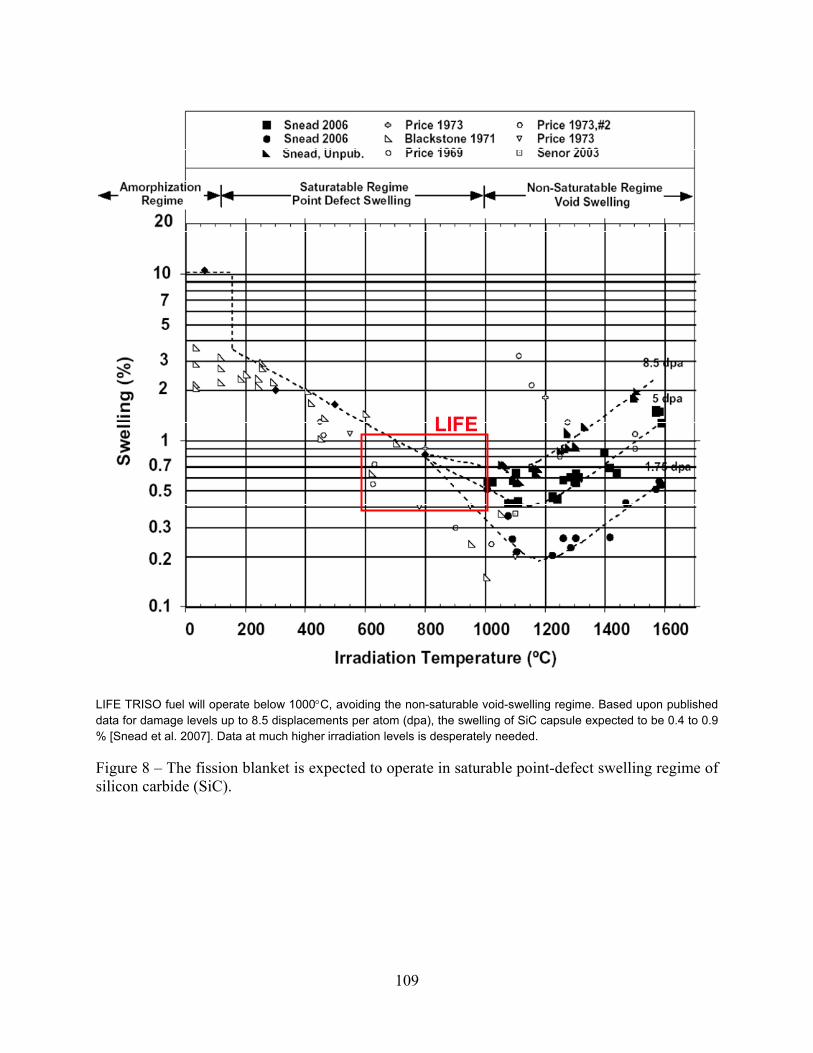
109
LIFE
LIFE TRISO fuel will operate below 1000°C, avoiding the non-saturable void-swelling regime. Based upon published data for damage levels up to 8.5 displacements per atom (dpa), the swelling of SiC capsule expected to be 0.4 to 0.9 % [Snead et al. 2007]. Data at much higher irradiation levels is desperately needed.
Figure 8 – The fission blanket is expected to operate in saturable point-defect swelling regime of silicon carbide (SiC).

110
Damage Levels Expected in Fission
Blanket
Range of Operating
Temperature for Fission Blanket
Swel
ling
(%)
Swel
ling
(%)
Irradiation Level (dpa) Temperature (°C)
Experiment: Snead et al 1998, Price 1969 & 1974Theoretical Predictions 2002
Damage Levels Expected in Fission
Blanket
Range of Operating
Temperature for Fission Blanket
Swel
ling
(%)
Swel
ling
(%)
Irradiation Level (dpa) Temperature (°C)
Experiment: Snead et al 1998, Price 1969 & 1974Theoretical Predictions 2002
Based upon a detailed kinetic model that accounts for the growth of dislocation loops and ion-beam irradiation studies at Kyoto University’s DuET facility, irradiation-induced swelling of SiC is expected to reach an asymptotic value of less than approximately one percent (~1%) as the dose increases [Ryazanov et al. 2002].
Figure 9 – Model predictions and ion-beam irradiation of SiC show no significant swelling of above approximately one displacement per atom (~ 1 dpa).

111
formation of between plane interstitial clusters
c-axis growth
a-axis shrinkage
Overall Large Volume Increase
c-axis growth
a-axis shrinkage
Overall Large Volume Increase
-5-4-3-2-10
a – axis
Kelly 1986250°C
200°C
170°C
150°C
0
5
10
15
20
25
30
0 2 4 6 8 10 12 14 16
Sw
ellin
g ( %
)
Kelly 1986150°C170°C
200°C
250°C
c – axis
Neutron Dose (1025 n/m2)
-5-4-3-2-10
-5-4-3-2-10
-5-4-3-2-10
a – axis
Kelly 1986250°C
200°C
170°C
150°C
0
5
10
15
20
25
30
0 2 4 6 8 10 12 14 160
5
10
15
20
25
30
0
5
10
15
20
25
30
0 2 4 6 8 10 12 14 160 2 4 6 8 10 12 14 16
Sw
ellin
g ( %
)
Kelly 1986150°C170°C
200°C
250°C
c – axis
Neutron Dose (1025 n/m2)
H-451 Nuclear Graphite Elevated temperature
The swelling of the lattice normal to the hexagonal planes (along c-axis) is substantially greater than that parallel to the planes (along a-axis). A material that swells isotropically, and to a lesser extent, is preferable [Zinkle 2008].
Figure 10 – The anisotropic swelling of the inner and outer pyrolytic graphite (IPyC and OPyC) layers in TRISO particles, as well as the graphite binder in the pebbles, is considered to be a significant barrier to the development of high burn-up TRISO fuels.

112
Frac
ture
Stre
ss (M
Pa)
Neutron Fluence (1025 n/m 2; E>0.5 MeV)
10 dpa 20 dpa 30 dpa
Return to “zero”Volume change
Zinkle [2008]
Figure 11 – The fracture strength of irradiated nuclear graphite is expected to be 25 to 45 MPa at 20 to 25 × 1025 n/m2, but may drop at higher doses.

113
Failures of HEU TRISO Particles at Various Levels of Burnup
1.E-09
1.E-08
1.E-07
1.E-06
1.E-05
1.E-04
1.E-03
0 10 20 30 40 50 60 70 80 90Burnup (%FIMA)
Failu
re (R
/B fo
r Kr-
85 m
)
NPR 1NPR 2
Capsule Failure Detected with Fission
Gas Leakage
Failures of HEU TRISO Particles at Various Levels of Burnup
1.E-09
1.E-08
1.E-07
1.E-06
1.E-05
1.E-04
1.E-03
0 10 20 30 40 50 60 70 80 90Burnup (%FIMA)
Failu
re (R
/B fo
r Kr-
85 m
)
NPR 1NPR 2
Capsule Failure Detected with Fission
Gas Leakage
The observed probability of failure appeared to be approximately 1 in 77,500 at this level of burn-up. Achieving such high burn-up with TRISO fabricated with natural or depleted uranium is a much greater challenge [Petti et al. 2004].
Figure 12 – TRISO fabricated from HEU has achieved relatively high burn-up (79% FIMA) with our failure of the SiC capsule and leakage of fission gas such as Kr-85.
IPyC
SiC
Crack
Crack
IPyC
SiC
Crack
Crack
The observed leakage of fission gas from these particles appears to be due to the pressurization-driven stress and associated fracture of the spherical silicon carbide pressure vessel [Petti et al. 2004].
Figure 13 – This figure shows fractures in the IPyC and SiC layers of a TRISO particle after reaching 79% FIMA.

114
TRISO Wall Stress vs. Burnup (FIMA)Based Upon Experimental Measurements of Fission Gas Pressure
0
100
200
300
400
500
600
700
800
0% 20% 40% 60% 80% 100%Burnup (FIMA)
TRIS
O W
all S
tres
s (M
Pa)
Stress in Enhanced SiC Capsule (Thickness ~ 90 µm)
Stress in NPR SiC Capsule (Thickness ~ 30 µm) SiC Strength
Thicker Capsule W
all = Lower Stress
Farmer et al. [2008]
Figure 14 – The failure of these TRISO particles appears to coincide with the point where the SiC wall stress exceeds the ultimate tensile stress (UTS) of the material. One method of mitigating the failure is to thicken the SiC wall.

115
Stress in TRISO SiC Capsule Wall Due to Fission Gas (Kr & Xe)
0
50
100
150
200
250
300
350
400
450
0 10 20 30 40 50 60 70 80 90 100
Time (years)
Wal
l Str
ess
(Mpa
)
Pebble (Secondary Containment)TRISO SiC Capsule (Primary Containment)
Published strength of SiCgreater than wall stress from fission gas accumulation
Fission Blanket in LIFE Engine
Cooler Interim Storage & Repository Conditions
TRISO particles for LIFE engine are designed with enough silicon carbide wall thickness for fission gas containment at 99.9% FIMA [Farmer and Zhao 2008].
Figure 15 – SiC wall stress verses fuel burn-up for enhanced TRISO fuel for LIFE engine.

116
Pseudo-color scale map shows pressure gradient surrounding crack during thermal pulsing
Crack propagation can be driven by static stress from fission gas accumulation, dynamic stress from neutron-thermal pulsing, and exacerbated by reactions of fission products with capsule
Kernel
Buffer
IPyC
SiC
OPyCSiCIPyC Protection Layer
Propagation of crack from IPyClayer into SiCcapsule
Model and calculations were done by Paul Demange et al. at LLNL [2008].
Figure 16 – Crack initiation at defects in silicon carbide layer are being accounted for in finite element model, and the calculations based upon that model.
1065
1070
1075
1080
1085
1090
1095
1.E-07 1.E-06 1.E-05 1.E-04 1.E-03 1.E-02 1.E-01
Time (seconds)
Tem
pera
ture
(K)
KernelL-PyCH-PyCSiC
SiC Capsule∆T ~ 6 to 7K
Kernel: 20K PulseSiC & PyC: 6 to 7K Pulse
Kernel∆T ~ 20K
1065
1070
1075
1080
1085
1090
1095
1.E-07 1.E-06 1.E-05 1.E-04 1.E-03 1.E-02 1.E-01
Time (seconds)
Tem
pera
ture
(K)
KernelL-PyCH-PyCSiC
SiC Capsule∆T ~ 6 to 7K
Kernel: 20K PulseSiC & PyC: 6 to 7K Pulse
Kernel∆T ~ 20K
The temperature pulse in the fuel particle was modeled by Ryan Abbot at LLNL [2008].
Figure 17 – TRISO will experience dynamic stress due to thermal pulsing at 10 ot 20 Hz, which may cause thermal fatigue.

117
LIFE
Survival of the SiC capsule is complicated by reactions involving fission products such as Pd. Deleterious low-melting eutectics form between fission products and encapsulation materials. A frequently cited example: is the Pd-Si reaction. Pd5Si phase formation threatens TRISO performance above 836°C. Thermal migration of kernal in temperature gradient can bring such fission products in close proximity of the SiC. Mitigation includes the use of sacrificial SiC in (or around) the kernel and a ZrC diffusion barrier. The TRISO operating temperature in LIFE is below the melting point of deleterious phases such as Pd5Si [Okamoto 2000].
Figure 18 – Phase diagram showing formation of low-melting Pd5Si as a result of the reaction of a Pd (fission product) with SiC capsule in TRISO fuel particle.

118
C-PuC-Pu O-PuO-Pu O-UO-U Pu-UPu-U
Si-CSi-C
Fission Product Accumulation in Fuel Pd5Si phase formation threatens TRISO performance above 836 °C
Pd-Si
LIFE
Pd-SiPd-Si
LIFE
Pd-C
LIFE
Pd-CPd-C
LIFE
Kaufman and Turchi are beginning to use the THERMOCALC code to model phase transformations in fission fuels at very high burn-up [2008].
Figure 19 – Phase transformations in fission fuels at high burn-up are being modeled. Relevant binaries include: C-Pu, O-Pu, O-U, Pu-U, Pd-Si, Pd-C, Si-C & others.
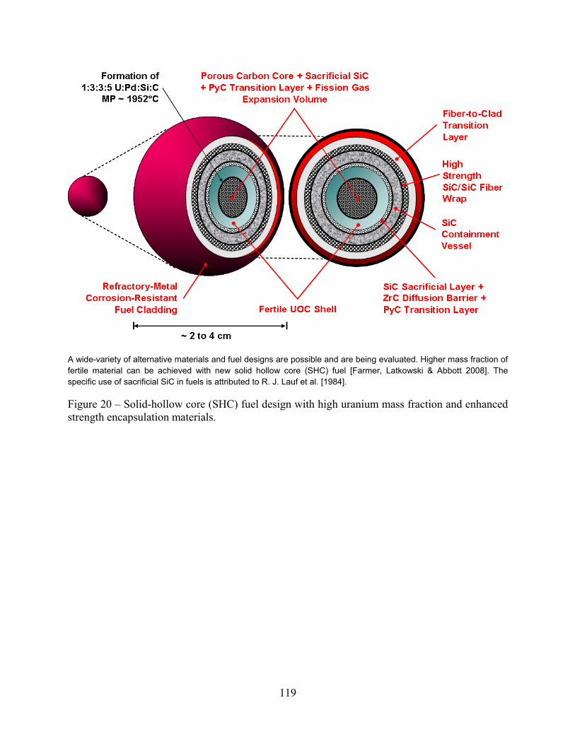
119
A wide-variety of alternative materials and fuel designs are possible and are being evaluated. Higher mass fraction of fertile material can be achieved with new solid hollow core (SHC) fuel [Farmer, Latkowski & Abbott 2008]. The specific use of sacrificial SiC in fuels is attributed to R. J. Lauf et al. [1984].
Figure 20 – Solid-hollow core (SHC) fuel design with high uranium mass fraction and enhanced strength encapsulation materials.

120
0
0
0
0
0
20% FIMA40% FIMA
60% FIMA
80% FIMA99.9% FIMA
Radial Distance (cm)
Tang
entia
l Str
ess
(MPa
)
0
100
-100
-200
-300
0.0 0.5 1.0 1.5 2.0
SiCBuffer
UOC
0
0
0
0
0
20% FIMA40% FIMA
60% FIMA
80% FIMA99.9% FIMA
Radial Distance (cm)
Tang
entia
l Str
ess
(MPa
)
0
100
-100
-200
-300
0.0 0.5 1.0 1.5 2.0
0
0
0
0
0
0
0
0
0
0
20% FIMA40% FIMA
60% FIMA
80% FIMA99.9% FIMA
Radial Distance (cm)
Tang
entia
l Str
ess
(MPa
)
0
100
-100
-200
-300
0.0 0.5 1.0 1.5 2.0
SiCBuffer
UOC
Finite Element Models for Possible New Fuel Configurations
Wall is well below yield stress
Wall is well below yield stress
Fertile material under compression
Fertile material under compression
Buffer
UOCSiC
High-strength corrosion-resistant shell
2 cm2 cm
Diffusion barrier
Model development and calculations were done by Paul Demange et al. at LLNL [2008].
Figure 21 – Predicted stress in the wall of solid hollow-core (SHC) fuel at fission gas pressures corresponding to 20, 40, 60, 80 and 99.9% FIMA.
Tangential Stress: 20% FIMA
Tangential Stress: 80% FIMAMesh for New Fuel Configuration
Tangential Stress: 99.9% FIMATangential Stress: 99.9% FIMA
Model development and calculations were done by Paul Demange et al. at LLNL [2008].
Figure 22 – Numerical analysis indicates a substantial strength margin in SHC pressure boundary. In all cases, the stress is well below the yield and ultimate tensile stresses of the wall material.

121
Cladding
SiCl(CH3)3
Binder
HNO3HMTA Urea
Enhanced TRISO Fuel
Uranium Ore
Pelletize
Broth
Drop Column
Water Wash
Alcohol Wash
Kiln Drying
Calcine
Tabling
Screening
PyC Reactor 1
Sintering
SiC Reactor
PyC Reactor 2
Tabling
Screening
Elutriation Columns
Compaction Press
Carburization Furnace
Heat Treat
Nat-U DU
HC GasCladding
SiCl(CH3)3
Binder
HNO3HMTA Urea
Enhanced TRISO Fuel
Uranium Ore
Pelletize
Broth
Drop Column
Water Wash
Alcohol Wash
Kiln Drying
Calcine
Tabling
Screening
PyC Reactor 1
Sintering
SiC Reactor
PyC Reactor 2
Tabling
Screening
Elutriation Columns
Compaction Press
Carburization Furnace
Heat Treat
Nat-U DU
HC Gas
This conceptual process was developed by Farmer et al. at LLNL [2008].
Figure 23 – Enhanced TRISO Process for Nat-U & DU.
LWR SNF
Fission Gas
Cladding Removal
Milling Slurry Pressing Sintering
Cladding
QA/QC
Zirconium Hulls Compaction
Vitrification
Cementation
Smaller Repository
Canister
Bare SNF Pellets
PEG BinderClad IMF LIFE Fuel
Inert Matrix
QA/QC
LWR SNF
Fission Gas
Cladding Removal
Milling Slurry Pressing Sintering
Cladding
QA/QC
Zirconium Hulls Compaction
Vitrification
Cementation
Smaller Repository
Canister
Bare SNF Pellets
PEG BinderClad IMF LIFE Fuel
Inert Matrix
QA/QC
This conceptual process was developed by Farmer et al. at LLNL [2008].
Figure 24 – Other processes may be needed for the conversion of light water reactor spent nuclear fuel into LIFE fuel.

122
This molten salt coolant is less prone to fire than liquid metal coolants, and can be used to breed tritium from the lithium. The corrosion of structural components of the LIFE engine in contact with this coolant must be understood [Kaufman and Turchi 2008].
Figure 25 – A binary mixture of BeF2 and LiF to form Li2BeF4 produces a eutectic composition with a low melting point of less than 400°C.

123
Molten salt fuel is not damaged by radiation and enables direct digestion of fertile/fissile materials. Phase transformations and actinide solubility in LIFE coolants and liquid fuels: BeF2-LiF, BeF2-ThF4, BeF2-UF4, BeF2-ZrF4, LiF-PuF3, LiF-ThF4, LiF-ZrF4, ThF4-UF4 and higher order systems. Regions of stable operation revealed for liquid fuels in LIFE engine [Kaufman and Turchi 2008].
Figure 26 – Phase diagram reveals regions of stable operation for liquid fuels in LIFE engine.

124
0
200
400
600
800
1000
1200
1400
0 100 200 300 400 500 600 700 800 900Temperature (C)
Yiel
d St
reng
th (M
Pa)
ODS PM 200012YWT9Cr-ODSNon-ODS FM Steel
LIFE
Next GenerationMaterials
0
200
400
600
800
1000
1200
1400
0 100 200 300 400 500 600 700 800 900Temperature (C)
Yiel
d St
reng
th (M
Pa)
ODS PM 200012YWT9Cr-ODSNon-ODS FM Steel
LIFE
Next GenerationMaterials
New ODS FM steels such as 9Cr-ODS & Kobe 12YWT have demonstrated exceptional tensile strength at high temperature; additional development is needed. ODS steels have exceptional tensile strength at high temperature; the next generation is expected to be better [Ukai and Fujiwara 2002; Klueh et al. 2007].
Figure 27 – New ODS FM steels such as 9Cr-ODS & Kobe 12YWT have demonstrated exceptional tensile strength at high temperature.

125
Elongation of ODS FM Steels
0
5
10
15
20
25
0 100 200 300 400 500 600 700 800 900Temperature (C)
Elon
gatio
n (%
)
0
1
2
3
4
5
6
7
8
Elon
gatio
n R
atio
(OD
S:FM
)
12YWT9Cr-ODSODS/FMS
LIFE
New ODS FM steels such as 9Cr-ODS & Kobe 12YWT have demonstrated exceptional creep resistance at high temperature; additional development is needed. ODS steels have exceptional tensile strength at high temperature; next generation is expected to be better [Ukai and Fujiwara 2002; Klueh et al. 2007].
Figure 28 – New ODS FM steels such as 9Cr-ODS & Kobe 12YWT have demonstrated exceptional creep resistance at high temperature; additional development is needed.

126
ODS 0.3 wt. % Y2O3
ODS 0.3 wt. % Y2O3ODS 0.3 wt. % Y2O3
+ 0.3% TiO2
ODS 0.3 wt. % Y2O3 + 0.3% TiO2
Non-ODS EUROFER 97
Non-ODS EUROFER 97
ODS 0.3 wt. % Y2O3
ODS 0.3 wt. % Y2O3ODS 0.3 wt. % Y2O3
+ 0.3% TiO2
ODS 0.3 wt. % Y2O3 + 0.3% TiO2
Non-ODS EUROFER 97
Non-ODS EUROFER 97
Oxide dispersion strengthened (ODS) steels are the most promising class of materials with the potential to be used at elevated temerpature under severe neutron exposure. Leading technology development of these mateirals has been conducted at JNC with an emphasis on cladding for fast reactors. Tensile yield strength (a) and total elongation (b) as function of test temperature of (-O-) as-received EUROFER 97, ( -�-) CRPP ODS EUROFER97 0.3 wt. % Y2O3 and (-□-) CRPP ODS EUROFER97 0.3 wt. % Y2O3 + 0.3 wt. % TiO2 [Schaublin et al. 2006].
Figure 29 – Additional data for EUROFER 97 showing the exceptional high-temperature strength and creep resistance of ODS steels.

127
Plastic Strain Behavior of 9Cr-ODS & 12Cr-ODS
1.E-06
1.E-05
1.E-04
1.E-03
1.E-02
1.E-01
1.E+00
1.E+01
1.E+02
1.E+03
1.E+00 1.E+01 1.E+02 1.E+03 1.E+04 1.E+05 1.E+06 1.E+07 1.E+08 1.E+09Nf (cycles)
Plas
tic S
trai
n R
ange
(%)
9Cr-ODS 873K 9Cr-ODS 923K9Cr-ODS 973K 9Cr-ODS 1023K12Cr-ODS 873K 12Cr-ODS 923K12Cr-ODS 973K 12Cr-ODS 1023K
No Data Beyond 100,000 Cycles
ODS ferritic-martensitic steel has longer fatigue life than conventional ferritic steels such as modified 9Cr-1Mo seel. Predictions based upon regression analysis of data for Nf < 100,000 cycles. Strain-controlled low-cycle fatigue tests were conducted for 9Cr-ODS and 12Cr-ODS at 873-1023K (600 to 800°C). The total strain ranges were controlled from 0.5 to 1.5% with a strain rate of 0.1% per second. Corresponding plastic strain ranged from 0.01 to 1%. The ODS has longer fatigue life than modified 9Cr-1Mo ferritic steel. The oxide dispersion strengthening prevented softening or hardening during cycling [Ukai and Ohtsuka 2007].
Figure 30 – Fatigue cycling of 9Cr-Fe and 12Cr-Fe ODS at temperatures from 600 to 800°C.

128
Expected dose in LIFE engine after 6 years operation
Expected dose in LIFE engine after 6 years operation
Gelles [1996]; Toloczko [2000]; Klueh and Harries [2001]; Zinkle [2008]
Figure 31 – Ferritric steels experience less irradiation-induced swelling than Type 316 austenitic stainless steel.

129
a b
c d
200 nm
a b
c d
200 nm
Overview of the microstructure in 9Cr-ODS irradiated with Ni ion at 500°C: (a) un-irradiated, (b) 5 dpa, (c) 50 dpa and (d) 150 dpa. No voids were found in all the conditions [Allen et al. 2005].
Figure 32 – Ion-beam irradiation of 9Cr-Fe ODS ferritic steel has shown no detectable void formation up to 150 displacements per atom.

130
a b
c d
100 nm
a b
c d
100 nm
Ion-beam irradiation of ODS steel has shown no detectable void formation up to 150 dpa. Oxide particles in 9Cr-ODS irradiated with Ni ion at 500°C: (a) un-irradiated, (b) 5 dpa, (c) 50 dpa, and (d) 150 dpa. The average size decreased from 11.7 nm for the un-irradiated case to 9.3 nm for the irradiated case of 150 dpa [Allen et al. 2005]
Figure 33 – Ion-beam irradiation of ODS steel has shown no detectable void formation up to 150 displacements per atom.

131
200 nm200 nm
He trapping at nano-precipitates in matrix
Dispersions of nano-precipitates mitigate irradiation-induced swelling attributable to helium. Helium trapping was observed at nano-precipitates in the matrix [Mansur and Lee 1991].
Figure 34 – Dispersions in matrix mitigate irradiation-induced swelling attributable to helium.

132
Friction stir, inertial and pressurized resistance welding provide best results Y2O3 particles remain in weld. Longitudinal cross-section in the vicinity of welded 9Cr-ODS steel cladding and its end-plug joined with pressurized resistance welding [Ukai et al. 2005].
Figure 35 – ODS FM steels have been successfully joined using industrial welding processes.

133
Fuel pins with ODS steel cladding and welded end-caps, joined with pressurized resistance welding, are being tested in BOR-60 reactor: 5% FIMA & 25 dpa by 2004; and 15% FIMA & 75 dpa by 2008. No failures of base metal or welds have been observed as 75-dpa level approached [Ukai et al. 2005].
Figure 36 – Fuel pins with ODS steel cladding and welded end-caps.

134
TMT Modified 9Cr-1MoTMT Modified 9Cr-1MoTMT Modified 9Cr-1Mo
Other approaches to dispersion-strengthening also exist, such as thermomechanical treatment (TMT). This process uses hot rolling to process 9Cr-1Mo and 12 Cr steels. Precipitates are formed at dislocations introduced during such processing. Dispersions of precipitates produced with TMT are much finer than those observed in conventionally processed 9-12 Cr steels. Mechanical properties are substantially improved. [R.L. Klueh et al. 2005].
Figure 37 – The microstructure of 9-12% Cr steels can be improved dramatically with hot rolling, which is known in the literature as thermomechanical treatment (TMT).

135
Molten Salt: Li2BeF4
Ferritic Steel (SUS430): Fe-18Cr
Oxide: Fe(Fe,Cr)2O4 ⇒ Cr2O3 + Fe2O3 Particles
Chromium Depletion Layer: Fe-18Cr ⇒ Fe-xCr
CrF3
Cr+3
FeF2
Fe+2Li+
TH
n
e-Cr
Fe
~200
nm
T+
Molten Salt: Li2BeF4
Ferritic Steel (SUS430): Fe-18Cr
Oxide: Fe(Fe,Cr)2O4 ⇒ Cr2O3 + Fe2O3 Particles
Chromium Depletion Layer: Fe-18Cr ⇒ Fe-xCr
CrF3
Cr+3
FeF2
Fe+2Li+
TH
n
e-Cr
Fe
~200
nm
T+
Note: The corrosion mechansim for ODS ferritic steel is complicated, as illustrated in this figure. First, the transmutation of lithium in the Li2BeF4 salt leads to the formation of acidic tritium fluoride, which has the chemical behavior of hydrofluoric acid. Based upon discussion in the literature, it is believed that gaseous beryllium containing species in equilibrium with the molten salt electrolyte may include LiBeF3, BeF2 and BeH2. The reduction of T+ at the ODS-salt interface may lead to the formation of reduced T2, with the simultaneous oxidation of Fe and Cr in the alloy to form Cr+3 and Fe+2. Atomic tritium adsorbed on the surface of the ODS steel could be absorbed by the steel, which could lead to tritium (hydrogen) induced cracking. The preferential dissolution of chromium into the Li2Be4 salt results in the formation of a chromium depletion layer, which lies below an oxide layer, consisting of a Fe(Fe,Cr)2O4, with an layer of dispersed Fe2O3 particles [Farmer 2008].
Figure 38 – Mechanism for corrosion of ODS ferritic steel, showing formation of the chromium depletion layer, and dissolution of iron and chromium into the molten salt.

136
1.E-08
1.E-07
1.E-06
1.E-05
1.E-04
1.E-03
1.E-02
1.E-01
1.E+00
1.E+01
1.E+02
1.E+03
1.E+04
-1.5 -1.0 -0.5 0.0 0.5Potential (V vs. T+/T)
Cur
rent
Den
sity
(A/c
m2)
Cathode Current [H+Fe+Cr] (A/cm2)
Anode Current [H+Fe+Cr] (A/cm2)
Difference [H+Fe+Cr] (A/cm2)
Emix = -0.21 V & dp/dt = 30 mil/year
Farmer [2008]
Figure 39 – Mixed potential theory applied to ODS ferritic steel without sacrificial beryllium anode in molten Li2BeF4 at 815°C.
1.E-05
1.E-04
1.E-03
1.E-02
1.E-01
1.E+00
1.E+01
1.E+02
1.E+03
1.E+04
-1.5 -1.3 -1.1 -0.9 -0.7 -0.5 -0.3 -0.1 0.1 0.3 0.5Potential (V vs. T+/T)
Log
Cur
rent
Den
sity
Cathode Current [H+Fe+Cr+Be] (A/cm2)Anode Current [H+Fe+Cr+Be] (A/cm2)Difference [H+Fe+Cr+Be] (A/cm2)
Emix = -0.61 V & dp/dt = 0.031 mil/year
Farmer [2008]
Figure 40 – Mixed potential theory applied to ODS ferritic steel with sacrificial beryllium anode in molten Li2BeF4 at 815°C.

137
Application of Mixed Potential Theory to LIFE EnginePenetration of ODS FM Steel (No Sacrificial Protection by Be) in Molten Salt at 815°C
1.E-081.E-071.E-061.E-051.E-041.E-031.E-021.E-011.E+001.E+011.E+021.E+031.E+041.E+051.E+061.E+071.E+081.E+091.E+10
-2.5 -2.0 -1.5 -1.0 -0.5 0.0 0.5 1.0Potential (V vs. T+/T)
Abs
olut
e To
tal C
urre
nt D
ensi
ty (A
/cm
2)
[H+Fe+Cr+Be] itotal (A/cm2)
[H+Fe+Cr] itotal (A/cm2)
Farmer [2008]
Figure 41 – A comparison of these two curves, taken from Figures 39 and 40 respectively, clearly show the cathodic shift of the open circuit corrosion potential due to galvanic coupling of beryllium and ODS steel at 815°C.

138
Corrosion of Steel Walls of LIFE Engine by Molten Salt Coolant Conservate Rate Assumption (316SS FLiNaK 815°C: 5.0 mil/yr & 3,000 ppm)
1.E-05
1.E-04
1.E-03
1.E-02
1.E-01
1.E+00
1.E+01
0.0001 0.0010 0.0100 0.1000 1.0000 10.0000 100.0000Time (years)
Wal
l Pen
etra
tion
(mm
)
1.E-02
1.E-01
1.E+00
1.E+01
1.E+02
1.E+03
1.E+04
1.E+05
1.E+06
Cr C
once
ntra
tion
(ppm
)
Linear-Rate Penetration mmConc-Limited Penetration mmLinear-Rate Concentration ppmConc-Limited Concentration ppm
Corrosion is assumed to slow as the concentration of dissolved Cr from the observed Cr depletion layer reaches saturation
Complete dissolution of wall in less than ten-to-twenty years
with linear rate law
Farmer [2008]
Figure 42 – Limited corrosive attack of ODS by molten salts, assuming a rate of attack of 5.0 mils per year, and saturation of the salt with chromium at a concentration of approximately 3,000 parts per million.

139
Corrosion of Steel Walls of LIFE Engine by Molten Salt CoolantConservate Rate Assumption (316SS FLiNaK 815°C: 70.1 mil/yr & 3,000 ppm)
1.0E-04
1.0E-03
1.0E-02
1.0E-01
1.0E+00
1.0E+01
1.0E+02
0.0001 0.0010 0.0100 0.1000 1.0000 10.0000Time (years)
Wal
l Pen
etra
tion
(mm
)
1.E+00
1.E+01
1.E+02
1.E+03
1.E+04
1.E+05
1.E+06
Cr C
once
ntra
tion
(ppm
)
Linear-Rate Penetration mm
Conc-Limited Penetration mm
Linear-Rate Concentration ppm
Conc-Limited Concentration ppm
Complete dissolution of wall in less than one year with linear rate law
Corrosion is assumed to slow as the concentration of dissolved Cr from the observed Cr depletion layer reaches saturation
Farmer [2008]
Figure 43 – Limited corrosive attack of ODS by molten salts, assuming a rate of attack of 70.1 mils per year, and saturation of the salt with chromium at a concentration of approximately 3000 parts per million.

140
Sealing TAD in C-22 Container
Containers Emplaced in Drifts
Pre-closure Cooling for 300 Years
Post-closure Period
LIFE Fuel
LIFE Engine
Dump Tank
Interim Storage for 50-100 Years
Truck/Rail Transport to Repository
Sealing Spent Solid Fuel in TAD
Sealing TAD in C-22 Container
Containers Emplaced in Drifts
Pre-closure Cooling for 300 Years
Post-closure Period
LIFE Fuel
LIFE Engine
Dump Tank
Interim Storage for 50-100 Years
Truck/Rail Transport to Repository
Sealing Spent Solid Fuel in TAD
Farmer et al. [2008]
Figure 44 – LIFE engine’s fuel-cycle story, including interim storage and disposal of waste in geological repository.

141
1E-06
1E-05
1E-04
1E-03
1E-02
1E-01
1E+00
0% 20% 40% 60% 80% 100%% FIMA
Mol
es P
er In
itial
U M
ole
UNpPuAmCmBkCf
Shaw et al. [2008]
Figure 45 – TRU inventory in fission blanket of LIFE engine (spent fuel) at various levels of burn-up (FIMA).

142
0.00.20.40.60.81.01.21.41.61.82.0
0% 20% 40% 60% 80% 95% 99%% FIMA
Mol
es P
er In
itial
U M
ole
Uranium Other ActinidesRare Earths MetalloidsPlatinum Group Metals Other Transition Metals TMNoble Gases Alkaline EarthsAlkalis Halogens
Shaw et al. [2008]
Figure 46 – Compositon of fission blanket of LIFE engine (spent fuel) at various levels of burn-up (FIMA).

143
78
1,750
0
200
400
600
800
1,000
1,200
1,400
1,600
1,800
2,000
LWR LIFE
Rea
ctor
s Pe
r Yuc
ca M
ount
ain
LIFE could extend the useful service life of deep geologic repositories by factor of twenty (×20). LIFE would require less repository capacity than LWR. Twenty times more electricity could be produced with nuclear before filling up repository [Farmer et al. 2008].
Figure 47 – Assuming current statutory limits for the disposal of spent nuclear fuel, a single Yucca Mountain repository could service more LIFE engines that light-water reactors.
1.5E+08
2.8E+09
0.0E+00
5.0E+08
1.0E+09
1.5E+09
2.0E+09
2.5E+09
3.0E+09
LWR LIFE
Tera
joul
es P
er Y
ucca
Mtn
LIFE could extend the useful service life of deep geologic repositories by factor of twenty (×20). Each reactor is assumed to have approximately 50-year service life: LWR = 1.2 GWe per 900 metric tons of heavy metal waste; LIFE = 1.0 GWe per 40 metric tons of heavy metal (MTHM) waste [Farmer et al. 2008].
Figure 48 – A single Yucca Mountain repository could enable more electrical power generation with a fleet of LIFE engines than with a fleet of light-water reactors.

144
0
500
1,000
1,500
2,000
2,500
3,000
3,500
4,000
2000 2050 2100 2150 2200Time (year)
Cap
acity
(GW
e)Total projected demand for power
Projected non-nuclear generating capacity constant by 2100
LWR fleet grows & provides 16% of future demand with energy deficit
Demand
LWR Fleet Falls Short of Need
Non-nuclear constant
Farmer et al. [2008]
Figure 49 – Electrical generating capacity for 1st Scenario: LWR fleet with no LIFE and energy deficit.

145
0
500
1,000
1,500
2,000
2,500
3,000
3,500
4,000
2000 2050 2100 2150 2200Time (year)
Cap
acity
(GW
e)Total projected demand for power
Projected non-nuclear generating capacity constant by 2100
LIFE intro 2030; grows to fill need & provides 50% of 2100 demand
LIFE intro 2030; aging LWR fleet phased out
Demand
LWR phasing out
LIFE filling need
Non-nuclear constant
Farmer et al. [2008]
Figure 50 – Electrical generating capacity for 2nd scenario: LIFE introduced in 2030 to fill the projected need for electrical power.
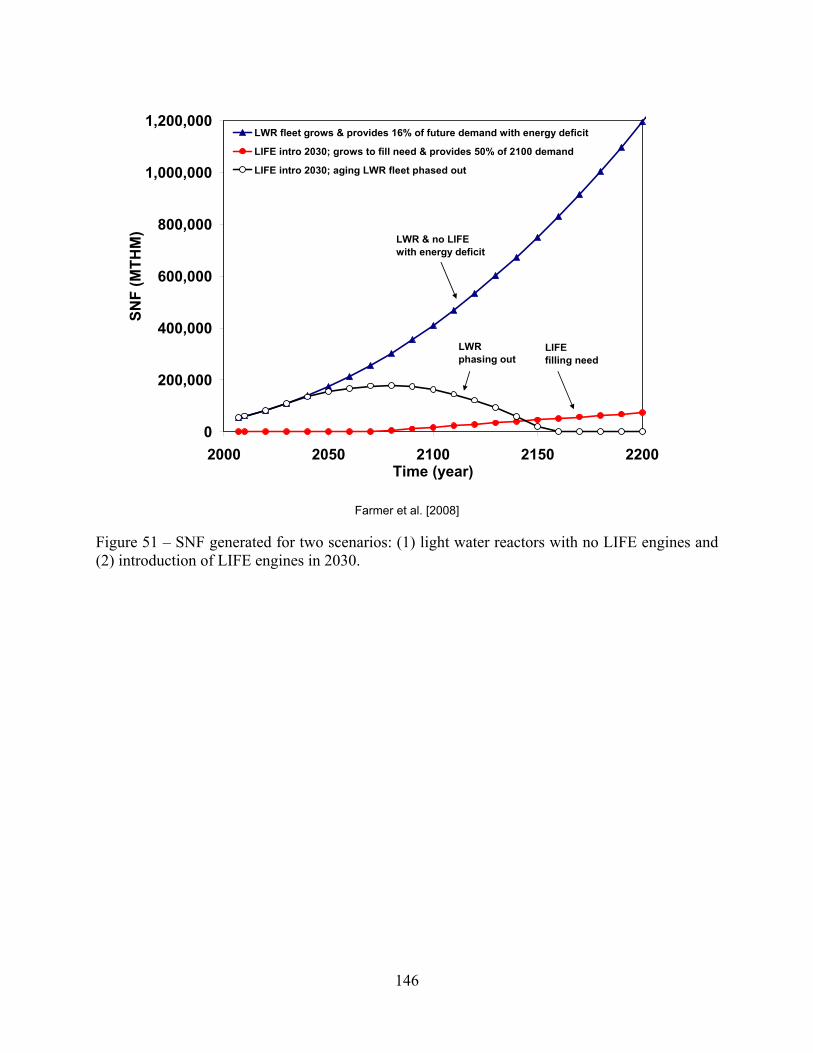
146
0
200,000
400,000
600,000
800,000
1,000,000
1,200,000
2000 2050 2100 2150 2200Time (year)
SNF
(MTH
M)
LWR fleet grows & provides 16% of future demand with energy deficit
LIFE intro 2030; grows to fill need & provides 50% of 2100 demand
LIFE intro 2030; aging LWR fleet phased out
LWR & no LIFEwith energy deficit
LWR phasing out
LIFE filling need
Farmer et al. [2008]
Figure 51 – SNF generated for two scenarios: (1) light water reactors with no LIFE engines and (2) introduction of LIFE engines in 2030.

147
0
5
10
15
20
25
30
35
40
2000 2050 2100 2150 2200 2250 2300Time (year)
Rep
osito
ry C
apac
ity (Y
ME)
LWR fleet grows & provides 16% of future demand with energy deficit
LIFE intro 2030; grows to fill need & provides 50% of 2100 demand
LWR & no LIFEwith energy deficit
LIFE filling need
Farmer et al. [2008]
Figure 52 – Repositories required for two scenarios: (1) LWR with no LIFE and (2) LIFE intro in 2030.

148
0
1,000
2,000
3,000
4,000
5,000
6,000
7,000
8,000
9,000
10,000
0 10 20 30 40 50 60Time (yrs)
Pu D
isch
arge
d fr
om R
eact
or (k
g-Pu
) LIFE ~ 99.5% FIMA kg-Pu LIFE ~ 92-93% FIMA kg-Pu LWR kg-Pu
Farmer et al. [2008]
Figure 53 – LIFE engine’s more complete burn generates far less plutonium per reactor than typical LWR.
0
2,000
4,000
6,000
8,000
10,000
12,000
0 10 20 30 40 50 60Time (years)
TRU
Dis
char
ged
from
Rea
ctor
(kg)
LIFE ~ 99.5% FIMA kg-TRU LIFE ~ 92-93% FIMA kg-TRU LWR kg-TRU
< 50 kg TRU at 99.5% FIMA
0
2,000
4,000
6,000
8,000
10,000
12,000
0 10 20 30 40 50 60Time (years)
TRU
Dis
char
ged
from
Rea
ctor
(kg)
LIFE ~ 99.5% FIMA kg-TRU LIFE ~ 92-93% FIMA kg-TRU LWR kg-TRU
< 50 kg TRU at 99.5% FIMA
Farmer et al. [2008]
Figure 54 – LIFE engine’s more complete burn also generates less TRU per reactor than LWR.

149
1.E-04
1.E-03
1.E-02
1.E-01
1.E+00
1.E+01
0 50 100 150 200 250 300 350Time (years)
TRU
Loa
ding
(kg/
pebb
le o
r rod
)
1.E-06
1.E-05
1.E-04
1.E-03
1.E-02
1.E-01
1.E+00
1.E+01
1.E+02
1.E+03
Act
ivity
(Ci/p
ebbl
e or
rod)
TRU Mass Per Pebble (kg/pebble)TRU Mass Per LWR Rod (kg/rod)Activity Per Pebble (Ci/pebble)Activity Per LWR Rod (Ci/rod)
Farmer and Zhao [2008]
Figure 55 – LIFE fuel pebble is less attractive target than LWR fuel rod since the pebble has less TRU and more radioactivity.
1.E+02
1.E+03
1.E+04
1.E+05
1.E+06
1.E+07
0 50 100 150 200 250 300 350Time (years)
Act
ivity
/kg-
TRU
(Ci/k
g)
LIFE LWR
Farmer and Zhao [2008]
Figure 56 – LIFE fuel (pebble) is a much less attractive target for theft than LWR fuel (rod): less TRU and more radioactivity.

150
Interim Storage for LIFE SNF:Thermal Power & Required Air Cooling
0
100
200
300
400
500
600
700
800
0 50 100 150 200 250 300Time (years)
Pow
er (k
W)
0
100
200
300
400
500
600
700
800
Coo
ling
Air
Flow
(m3/
min
)
Total Power (kW)Container Power (kW) - 99% FIMACooling Air (m3/min)
Farmer et al. [2008]
Figure 57 – Power Curves for interim storage of LIFE spent fuel in standard transportation, aging and disposal container during dry interim storage with area fraction for heat transfer between TRISO pebbles of 0.10.

151
Interim Storage for LIFE SNF:Temperature Profiles
20
70
120
170
220
270
320
370
420
0 50 100 150 200 250 300Time (years)
Tem
pera
ture
(deg
C)
Air TemperatureAir-Container Interface TemperatureContainer-Fuel Interface TemperatureFuel Centerline Temperature
Farmer et al. [2008]
Figure 58 – Temperature and cooling air required for LIFE spent fuel in standard transportation, aging, and disposal container during dry interim storage with area fraction for heat transfer between TRISO pebbles of 0.10.
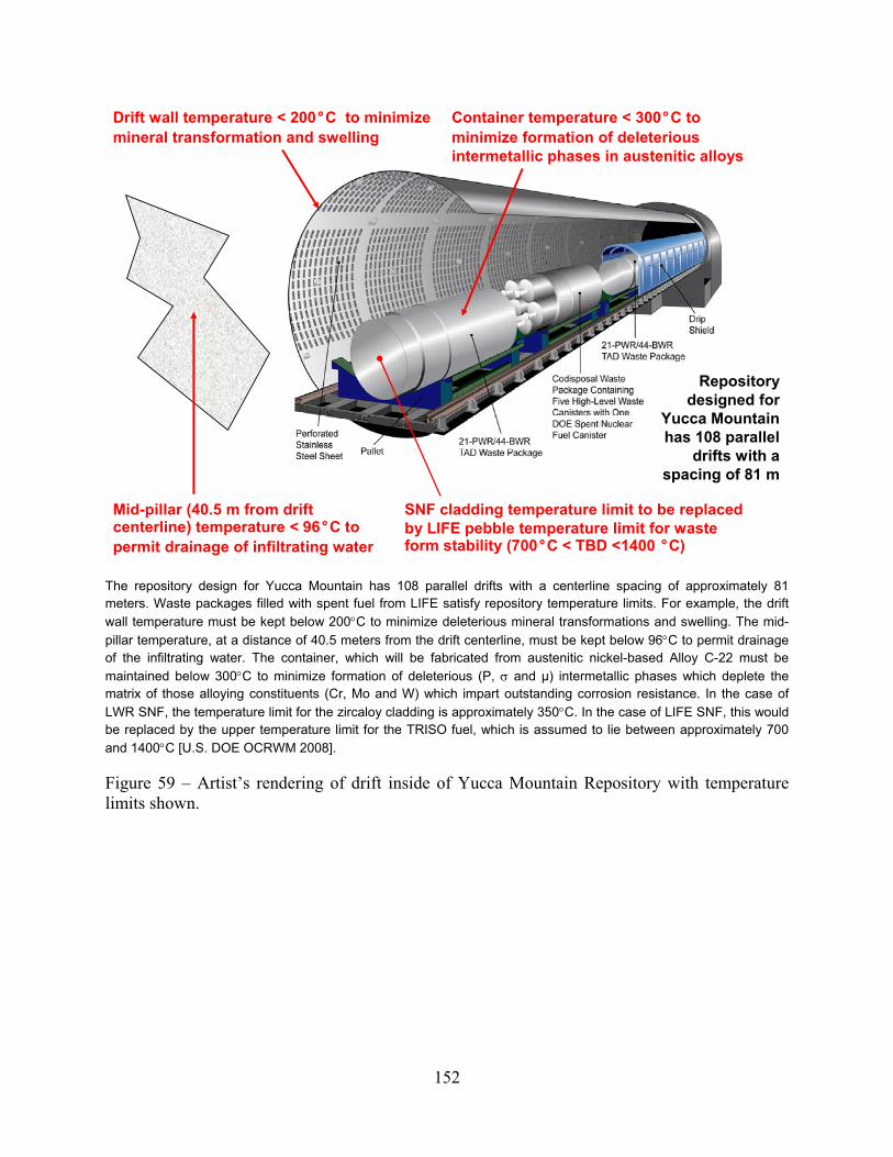
152
Container temperature < 300°C to minimize formation of deleterious intermetallic phases in austenitic alloys
Drift wall temperature < 200°C to minimize mineral transformation and swelling
Mid-pillar (40.5 m from drift centerline) temperature < 96°C to permit drainage of infiltrating water
Repository designed for
Yucca Mountain has 108 parallel
drifts with a spacing of 81 m
SNF cladding temperature limit to be replaced by LIFE pebble temperature limit for waste form stability (700°C < TBD <1400 °C)
The repository design for Yucca Mountain has 108 parallel drifts with a centerline spacing of approximately 81 meters. Waste packages filled with spent fuel from LIFE satisfy repository temperature limits. For example, the drift wall temperature must be kept below 200°C to minimize deleterious mineral transformations and swelling. The mid-pillar temperature, at a distance of 40.5 meters from the drift centerline, must be kept below 96°C to permit drainage of the infiltrating water. The container, which will be fabricated from austenitic nickel-based Alloy C-22 must be maintained below 300°C to minimize formation of deleterious (P, σ and µ) intermetallic phases which deplete the matrix of those alloying constituents (Cr, Mo and W) which impart outstanding corrosion resistance. In the case of LWR SNF, the temperature limit for the zircaloy cladding is approximately 350°C. In the case of LIFE SNF, this would be replaced by the upper temperature limit for the TRISO fuel, which is assumed to lie between approximately 700 and 1400°C [U.S. DOE OCRWM 2008].
Figure 59 – Artist’s rendering of drift inside of Yucca Mountain Repository with temperature limits shown.

153
Comparison of LIFE & LWR SNF Containers:Thermal Power per SNF Container
1E-01
1E+01
1E+03
1E+05
1E+07
1 10 100 1,000 10,000 100,000 1,000,000
Time (Years)
Ther
mal
Pow
er (W
atts
/Con
tain
er) LIFE 95% FIMA
LIFE 99% FIMALIFE 99.9% FIMALWR SNF
s
Thermal power of LIFE SNF decreases with increasing burn-up (%FIMA). The difference in FIMA power is burnup of actinides; fission products are in quasi-equilibrium. The higher LIFE thermal power can be accommodated by repository design options. Linear power density in the repository (kW/m) decreases with increasing burn-up (FIMA) [Blink et al. 2008].
Figure 60 – A comparison of the heat generated by containers filled with LIFE and LWR spent nuclear fuels during the first million years.

154
0
25
50
75
100
125
150
175
200
225
0 10 20 30 40 50 60 70 80 90Time (yr)
Tem
pera
ture
(°C
)
Waste PackageDrift WallVentilation Air
Ventilation will be used to keep the temperature of LIFE SNF containers within limits during the pre-closure period of the repository, in a manner analogous to that for LWR SNF. This prediction of LIFE SNF container (waste package) temperature is for containers located near the drift’s ventilation air exit. The ventilation air flow is assumed to be approximately 15 cubic meters per second (15 m3/s), with a velocity in the driftrs of approximately 1.79 miles per hour (1.7 mph). The saw-tooth pattern in the temperature-time profile is due to the phased, sequential periodic emplacement of the containers from the LIFE engine every 10 years. The burn-up is assumed to be approximately 99% FIMA [Blink et al. 2008].
Figure 61 – Temperature of the container filled with LIFE spent fuel (waste package), drift wall, and ventilation air used for cooling during the pre-closure sequential emplacement of finge containers (from single LIFE engine) in a repository drift, assuming no preceding period of interim storage for cooling.

155
Comparison of LIFE & LWR SNF Containers:Activity per SNF Container
1E+01
1E+02
1E+03
1E+04
1E+05
1E+06
1E+07
1E+08
1 10 100 1,000 10,000 100,000 1,000,000Time (Years)
Act
ivity
(Ci/C
onta
iner
)
FIMA 95%FIMA 99%FIMA 99.9%CSNF
The radioactivity of LIFE SNF has also been modeled and decreases as the burn-up (%FIMA) increases. The difference in FIMA power is burnup of actinides; fission products are in quasi-equilibrium. Estimates for LIFE include some radionuclides (RNs) not included in the available estimates for the commercial spent nuclear fuel (CSNF). For example, Cm-246 is more important in LIFE SNF than in LWR SNF due to the high neutron fluence in LIFE (8 n captures). Other RNs such as Zr-93 and Nb-93m need to be closely scrutinized to determine why they are not included in available estimates for CSNF [Blink et al. 2008].
Figure 62 – A comparison of the radioactivity from containers filled with LIFE and LWR spent nuclear fuels during the first million years.

156
0.00001
0.0001
0.001
0.01
0.1
1
10
100
1000
14C
36C
l79
Se93
Zr99
Tc12
6Sn
129I
135C
s22
6Ra
227A
c22
9Th
230T
h23
1Pa
233U
234U
235U
236U
238U
237N
p23
9Pu
240P
u24
2Pu
244P
u24
6Cm
248C
m
Nuclide
(Ci/j
oule
LIF
E)/(C
i/jou
le L
WR
)
Plotted is the maximum ratio (at any time) of the activities per unit electrical energy generated by LIFE SNF (DU, 99% FIMA) and LWR SNF (41.2 GWt-day per metric ton ~ 4.3% FIMA) [Shaw et al. 2008].
Figure 63 – Comparison of energy-normalized inventories of radionuclides considered to be significant for the performance of the Yucca Mountain repository.

157
29
8100
5.113
8.33.5
0.0001
0.001
0.01
0.1
1
10
100
1000
10000
14C
36C
l
79Se
93Zr
99Tc
126S
n12
9I
135C
s
226R
a22
7Ac
229T
h
230T
h
231P
a
233U
234U
235U
236U
238U
237N
p
239P
u24
0Pu
242P
u
244P
u24
6Cm
248C
m
Nuclide
(Ci/M
T LI
FE)/(
Ci/M
T C
SNF)
Plotted is the maximum ratio (at any time) of the specific activities (Ci/MTIHM) of LIFE SNF (DU, 99% FIMA) and LWR SNF (41.2 GWt-day per metric ton ~ 4.3% FIMA). Most significant nuclides considered significant in the Yucca Mountain TSPA are less abundant in LIFE SNF, but several are higher. Some nuclides in LIFE SNF are not accounted for in the Yucca Mountain TSPA (93Zr, 244Pu, 246Cm, 248Cm) [Shaw et al. 2008].
Figure 64 – Comparison of mass-normalized inventories of radionuclides considered to be significant for the performance of the Yucca Mountain repository.

158
0.0001
0.001
0.01
0.1
1
0 200 400 600 800 1000
Thousands of Years
Ave
rage
ann
ual d
ose
(mre
m/y
r/EJ
elec
tric
ity)
YMP TSPA
LIFE 99% FIMA
The dose predicted by performance assessment that is attributable to the generation of a given quantity of electricity is approximately ten times (~10×) less for LIFE SNF than for LWR SNF [Shaw et al. 2008].
Figure 65 – The risk-to-benefit ratio for a Yucca Mountain repository completely filled with spent nuclear fuel from a fleet of LIFE engines compared to that of a similar repository completely filled with spent fuel from a fleet of light water reactors, showing risk for the LIFE scenario.

159
0.1
1
10
100
1000
0 200 400 600 800 1000
Thousands of Years
Ave
rage
ann
ual d
ose
(mre
m/y
r)fr
om 1
Yuc
ca M
tn
YMP TSPA
LIFE 99% FIMA
Proposed 10 CFR 63 limit
Scaled dose from a Yucca-Mountain-like repository containing LIFE SNF is of the same order of magnitude as the Yucca Mountain TSPA-LA results, and well below the proposed regulatory limit. Major contributors to long term dose from LIFE waste are 129I, 135Cs, and 242Pu. The LIFE Project will need to do performance assessment calculations using qualified and accepted software tools such as GoldSim in the future [Shaw et al. 2008].
Figure 66 – Simple scaling suggests that the risk of a Yucca Mountain repository completely filled with spent nuclear fuel from LIFE engines is slightly more than that of a repository completely filled with spent nuclear fuel from a fleet of light-water reactors, but still well within the statutory limits established with 10 CFR 63.

160
Radio Frequency Quadrapole
(RFQ)
Coupled Cavity Drift Tube LINAC
(CCDTL)
Spoke Resonator Super Conductive
Cavities
PBE-Cooled Transmutation
Reactor
Thermal-Electric Conversion
Pyro Processing & Separation of
DU & TRU40 MW – 110 mA
21.2 MeV 1000 MeV
2000 MWth
6.7 MeV
700 MWe
Recirculation 10-15%
TRU: 33 MT / 50 yr
FP: 33 MT / 50 yr
Pu ~ 1000 ppm
DU: 650 MT / 50 yr SNF: 683 MT / 50 yr
125-300°C
Efficiency ~ 45%
Compression Laser Ignition Laser
Target Fabrication
TRISO Fabrication
FLIBE-Cooled LIFE Engine
Thermal-Electric Conversion
1000-2000 MWe2000-3000 MWth
550-650 kJ (10 MW) 75 kJ (1 MW)
2ω / 20 Hz / 25 ns 1ω / 20 Hz / 10 ps
Recirculation 10-15%
SNF: 40 MT / 50 yr
FP: 40 MT / 50 yr
Pu ~ 1000 ppm
700-800°C
Efficiency ~ 45%
Radio Frequency Quadrapole
(RFQ)
Coupled Cavity Drift Tube LINAC
(CCDTL)
Spoke Resonator Super Conductive
Cavities
PBE-Cooled Transmutation
Reactor
Thermal-Electric Conversion
Pyro Processing & Separation of
DU & TRU40 MW – 110 mA
21.2 MeV 1000 MeV
2000 MWth
6.7 MeV
700 MWe
Recirculation 10-15%
TRU: 33 MT / 50 yr
FP: 33 MT / 50 yr
Pu ~ 1000 ppm
DU: 650 MT / 50 yr SNF: 683 MT / 50 yr
125-300°C
Efficiency ~ 45%
Compression Laser Ignition Laser
Target Fabrication
TRISO Fabrication
FLIBE-Cooled LIFE Engine
Thermal-Electric Conversion
1000-2000 MWe2000-3000 MWth
550-650 kJ (10 MW) 75 kJ (1 MW)
2ω / 20 Hz / 25 ns 1ω / 20 Hz / 10 ps
Recirculation 10-15%
SNF: 40 MT / 50 yr
FP: 40 MT / 50 yr
Pu ~ 1000 ppm
700-800°C
Efficiency ~ 45%
Another sub-critical system that has been proposed for the burning of spent nuclear fuel is known as accelerator transmutation of waste (ATW). In this process, reprocessing is used to separate TRU from LWR SNF for burning in a lead-bismuth cooled reactor. In contrast, SNF can be burned in LIFE without significant isotopic enrichment or chemical reprocessing [Farmer 2008].
Figure 67 – A side-by-side comparison of two proposed fuel cycles, one for the accelerator transmutation of waste and another with LIFE engines.

161
1.52 1.30 1.60 1.50
2.42
5.90 5.60
2.10
7.60
1.802.42
5.70
4.00
0.0
1.0
2.0
3.0
4.0
5.0
6.0
7.0
8.0
LaN
i5
LaC
uNi4
La0.
7Ce0
.3N
i5
Mm
0.85
Ce0
.15N
i5
Mm
1.05
Ni4
.97A
l0.0
3
Vana
diiu
m
V (0
.93%
Si)
Nio
bium
Mag
nesi
um FeTi
FeTi
Mn
Mg0
.93N
i0.0
7
Ala
nate
(SN
L)
g-H
2/10
0g-M
Figure 68 – LIFE requires safe on-site tritiuim storage with solid-state tritide systems, which have been demonstrated on relatively large scale.
Solid-state tritium storage media must be selected that will release the tritium with relatively mild temperature swings near ambient temperature. In Mg-Ni system may be an attractive system, with both high storage capacity, and modest operating temperature.
Figure 69 – Equilibrium pressure as a function of temperature for numerous solid-state storage media for hydrogen isotopes including tritium.
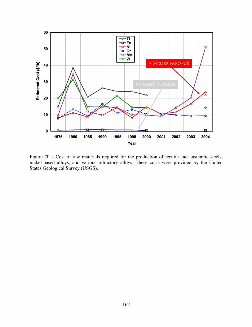
162
0
10
20
30
40
50
60
1975 1980 1985 1990 1995 1998 2000 2001 2002 2003 2004Year
Estim
ated
Cos
t ($/
lb)
TiFeNiCrMoW
Ni-based material
Fe-based material
0
10
20
30
40
50
60
1975 1980 1985 1990 1995 1998 2000 2001 2002 2003 2004Year
Estim
ated
Cos
t ($/
lb)
TiFeNiCrMoW
Ni-based material
Fe-based material
Figure 70 – Cost of raw materials required for the production of ferritic and austenitic steels, nickel-based alloys, and various refractory alloys. These costs were provided by the United States Geological Survey (USGS).

163
Beryllium Availability for LIFE Engine Neutron Multiplication & Cooling
15,593
155 179
23.5
1
10
100
1,000
10,000
100,000
LIFE Plant Proven US Reserves US Mine Shipments2006
World MineShipments 2006
MT
Be
Met
al
Figure 71 – The proven U.S. reserves, U.S. mine shipments, and world mine shipments of beryllium expressed in metric tons.
Beryllium Availability for LIFE Engine Neutron Multiplication & Cooling
1
664
7 8
0
1
10
100
1000
LIFE Plant Proven US Reserves US Mine Shipments2006
World MineShipments 2006
Equi
vale
nt L
IFE
Engi
nes
Figure 72 – The number of LIFE engines that can be built from proven US reserves, US mine shipments, and world mine shipments of beryllium.

164
Lithium Availability for Fueling & Cooling LIFE Engine
760,000
740
21,000
23.25
1
10
100
1,000
10,000
100,000
1,000,000
10,000,000
LIFE Plant Proven USReserves
US Consumption +Export - Import
2006
World Production2006
Li M
etal
(MT)
Figure 73 – The proven U.S. reserves, U.S. consumption and exports, deducting imports, and world production of lithium, expressed in metric tons.
Lithium Availability for Fueling & Cooling LIFE Engine
1
32,688
32
903
0
1
10
100
1,000
10,000
100,000
1,000,000
LIFE Plant Proven USReserves
US Consumption +Export - Import 2006
World Production2006
Equi
vale
nt L
IFE
Engi
nes
Figure 74 – The number of LIFE engines that can be built from proven U.S. reserves, U.S. consumption and exports, deducting imports, and world production of lithium.

165
Phase Transformatio
n Model
Corrosion Model
Target Fusion-Physics Model• Neutrons, ions, X-rays & γ-rays
Blanket Fission-Physics Model• Isotope Concentrations• Power Generation
Heat Transfer Model• System Temperature• Component Temperature
Radiation Damage Model
Stress Analysis Model• Thermal & Radiation Creep• Static Stress (Fission Gas Pressure)• Dynamic Stress (Thermal Pulsing)
Fracture Mechanics Model
Service Life Prediction Model• Deterministic Predictions• Probabilistic Risk Assessment
Figure 75 – A systematic approach to materials modeling will enable design of next-generation materials.
Test Reactors• ATR ~ 10 dpa/year• HIFR ~ 20 dpa/year
Test Reactors• ATR ~ 10 dpa/year• HIFR ~ 20 dpa/year
Ion Beam Systems• IBA ~ 50 dpa/day• CAMS ~ 50 dpa/day
Three accelerators needed:(1) heavy ions, (2) helium & (3) hydrogen
CEA Chamber
Best known method for accelerated testing
Figure 76 – Accelerated testing of materials will be done in three-beam accelerator.

166
Appendix A
Other High-Temperature Materials as Building Blocks In the future, new high-performance first-wall composite materials could exploit the high melting points, and low vapor pressures of a broad range of known compounds. These compounds fall into several broad classes, including a wide variety of carbides, nitrides, oxides, intermetallics, silicides, as well as several refractory metals and alloys, some of which have already been discussed. Several refractory alloys have been explored for possible application as first-wall materials in fusion reactors [Ursu 1985; patent literature]. Several specific alloy compositions are given below.
Carbides
• 3500-4000°C: (Ta,Cr,Zr)C, HfC, Tac, ZrC, NbC
• 3000-3500°C: Ta2C, TiC
• 2500-3000°C: SiC, VC, W2C, MoC, ThC2, WC
• 2000-2500°C: B4C, Al4C3
• 1500-2000°C: Te3C
Nitrides
• 3000-3500°C: HfN, TaN, BaN
• 2500-3000°C: ZrN, TiN, UN, ThN
• 2000-2500°C: AlN, Be3N, NbN, VN
Borides
• 3000-3500°C: HfB, TaB2, ZrB2, NbB2
• 2500-3000°C: TiB2, Ta3B4
• 2000-2500°C: VB2, TaB, WB, W2B5, TiB, MoB, CrB2, MoB2, CrB, Ta3B2, TiB, Mo2B
Intermetallics
• 3000-3500°C: Re5W2
• 2500-3000°C: MoW
• 2000-2500°C: CrAl, Mo3Al, UBe2, Zr5Sn3

167
• 1500-2000°C: Cr3Ta, NiAl
Silicides
• 2500-3000°C: Ta3Si
• 2000-2500°C: TaSi2, W5Si3, Zr2Si, WSi2, ZrSi, V3Si, Mo3Si, Mo4Si, MoSi2
Refractory alloys are of particular interest for fusion and fusion-fission hybrid reactors due to: relatively high melting points, which enable this type of material to maintain high strength at elevated temperature. Refractory alloys are much more formable than ceramics. Refractory metals are found in Groups IVB, VB and VIB of the periodic table, and include Nb, Ta, Cr, Mo, and W. Specifically, these materials include:
Carbon
The favorable high-temperature properties of graphite have led to its prolific use in aerospace applications. The graphitic form consists of parallel planes of carbon atoms, arranged in hexagonal cells. This unique structure enables graphite to form intercalation compounds with lithium cations (Li+). The tendency of graphite to from intercalation compounds with the lithium cations in FLIBE and FLINABE would prove problematic in a fusion-fission hybrid reactor. This well-known characteristic has led to the use of graphite as the preferred cathode material in virtually all modern high-performance rechargeable Li-ion batteries.
• AW 12.011, AN 6, MP 3367°C, SUB 3367±25°C, BP 4827°C
• Amorphous : ρ = 1.8 to 2.1 g/cm3 (25°C)
• Graphite: ρ = 1.9 to 2.3 g/cm3 (25°C)
• Diamond: 3.15 to 3.5 g/cm3 (25°C)
Tungsten
Tungsten is also known as Wolfram. It is a true metal with the highest melting point and lowest vapor pressure; tantalum-carbide/graphite composite melts at 6760 °C. It forms oxides that are relatively insoluble in acid, and is one of the alloying elements added to austenitic nickel-chromium-molybdenum alloys to stabilize passive film in acidic oxidizing regions of the Pourbaix diagram, and significantly increases the pitting resistance equivalence number (PREN) of these alloys. In regard to the current nuclear fuel cycle, it is a key ingredient of nickel-based Alloy C-22 that will be used to construct 11,000 disposal containers for the Nation’s 70,000 MTU spent nuclear fuel.
• AW = 183.85, AN 74, MP 3410±20°C, BP 5660°C, ρ = 19.3 g/cm3 (20°C)
• Ore: wolframite [(Fe,Mn)WO4], scheelite [CaWO4], huebnerite [MnWO4], ferberite [FeWO4]

168
• Sources: California, Colorado, South Korea, China, Bolivia, Ukraine/Russia
Tantalum
• AW = 180.95, AN 73, MP 2996°C, BP 5424±100°C, ρ = 16.654 g/cm3 (20°C)
• Ore: columbinte-tantalite [(Fe,Mn)(Mn,Ta)2)6]
• Sources: Zaire, Brazil, Mozambique, Thailand, Portugal, Nigeria, Canada
Molybdenum
This material is a byproduct of copper and tungsten mining; many ultra-high strength steels with yield strengths above 300,000 pounds per square inch (psi) contain this element at 0.25 to 8 weight percent. This alloying element is also added to austenitic stainless steels and nickel-chromium-molybdenum alloys (Type 316L Stainless, HastelloysTM and InconelsTM) to stabilize passive film in acidic oxidizing regions of the Pourbaix diagram, and significantly increases the pitting resistance equivalence number (PREN) of these materials. Even more important than tungsten in regard to its role in high-performance nickel-based alloys, it is a key ingredient of nickel-based Alloy C-22. In regard to the current nuclear fuel cycle, high-molybdenum Alloy C-22 will be used to construct 11,000 disposal containers for the Nation’s 70,000 MTU spent nuclear fuel; sulfide serves as solid lubricant; catalyst; essential trace element for plant nutrition. Due to the entry of the Chinese into the world metals market, the costs of such high-performance alloys have skyrocketed. Recent procurements of Alloy C-22 were at a cost of $37 per pound, driven significantly by the cost of both nickel and molybdenum.
• AW = 95.94, AN 42, MP 2617°C, BP 4612°C, ρ = 10.22 g/cm3 (20°C)
• Ore: molybdenite [MoS2], wulfenite [(PbMoO4)3], powellite [Ca(Mo,W)O4]
• Sources: relatively plentiful
Molybdenum Alloys
• 99.4%Mo-0.5%Ti-0.08%Zr-0.01%C
• 93%Mo-7at.%Re to 70%Mo-30at.%Re
Niobium
Niobium is also known as Columbium, and is unique in that it has superconductive properties.
• AW = 92.91, AN 41, MP 2468±10°C, BP 4742°C, ρ = 8.57 g/cm3 (20°C)
• Ore: associated with carbonatities; niobite-tantilite; pyrochlore; euxenite
• Sources: Canada, Brazil, Nigeria, Zaire, Ukraine/Russia

169
Niobium Alloys
• 81%Nb-10%Mo-3%Ti-1%Zr
Vanadium
Vanadium forms refractory alloys that have been shown to have reasonably good corrosion properties in the presence of liquid lithium, FLIBE and FLINABE. This element is plentiful, and is found in over 65 different minerals. Its ores are frequently associated with phosphate rock and iron ore.
• AW = 50.94, AN 23, MP 1890±10°C, BP 3380°C, ρ = 6.11 g/cm3 (18.7°C)
• Ore: carnotite, roscoelite, vanadinite, patronite
• Sources: relatively plentiful
Vanadium Alloys
• 80%V-20%Ti
• (81-94)%V-(3-9)%Cr-(3-10)%Ti
• V-4Cr-4Ti
Chromium
Chromium is produced through the chemical reduction of oxide ore with metallic aluminum, which is produced electrolytically. From an environmental point of view, chromium is paradoxical: hexavalent chromium is carcinogenic, while trivalent chromium is essential for human life. Chromium is the element primarily responsible for passive film formation on iron-based 300-series stainless steels, including Types 304L and 304L. The passive film formed from chromium is stable over modest ranges of potential and pH. Due to its role in the passivity of steels, it is also a key ingredient of nickel-based Alloy C-22. As previously discussed in regard to tungsten and molybdenum, Alloy C-22 will be used to construct 11,000 disposal containers for the Nation’s 70,000 MTU spent nuclear fuel.
• AW = 51.996, AN 24, MP 1857±20°C, BP 2672°C, ρ = 7.18 g/cm3 (20°C)
• Ore: chromite [FeCr2O4]
• Sources: Southern Rhodesia, Russia/Ukraine, Turkey, Iran, Albania, Finland, Madagascar, Philippines

170
Platinum
Platinum occurs in native form as silvery-white metal, and usually found with lesser amounts of iridium, osmium, palladium, ruthenium, and rhodium. This white precious metal recognized by pre-Colombian men in the Americas. Platinum is unique in its outstanding catalytic and electrocatalytic properties, and is the catalyst of choice in proton exchange membrane fuel cells for both oxygen cathodes and hydrogen anodes, at loadings of 0.5 to 2.0 mg/cm2. As the world moves towards a hydrogen economy, the demands and costs are likely to rise significantly, until alternative electrocatalysts are created through bandgap engineering.
• AW = 195.09, AN 78, MP 1772°C, BP 3827±100°C, ρ = 21.45 g/cm3 (20°C)
• Ore: metal [native form]; sperrylite [PtAs2]
• Sources: Colombia, Canada, Western United States, Others
Titanium
The National Strategic Reserve of Titanium Metal is located in Henderson, Nevada, at TIMET, Incorporated. At the present time, the Department of Defense is investing heavily in processes to achieve dramatic reductions in the cost of titanium, by shifting from chemical to electrolytic reduction, as was done for aluminum production in the early 20th century. It is frequently alloyed with small amounts of palladium to enhance its environmental resistance. Approximately 12.1 weight percent of Moon Rocks collected during Apollo 17 mission consisted of rutile (TiO2), and most white paint pigment consists of rutile, which was used as a safe alternative to lead oxide. This particular oxide has unique photocatalytic properties. Titanium is strong lightweight metal used for many aerospace and defense applications. It is extremely corrosion resistant in saline environments, and is one of the materials of choice in desalination plants. In regard to the current nuclear fuel cycle, more than 10,000 titanium alloy (Ti Grade 7) drip shields are planned for emplacement in Yucca Mountain to protect waste packages from rock drop and dripping ground water, and will cost several billion dollars.
• AW = 47.90, AN 22, MP 1660±10°C, BP 3287°C, ρ = 4.54 g/cm3 (20°C)
• Ore: rutile, ilmenite, sphene
• Sources: relatively plentiful