Embed Size (px)
Citation preview
Confidential
English 8/2019. Rev 0.0
LIB System for UPS
Installation Manual (136S)

Confidential
English 8/2019. Rev 0.0
Read this manual carefully before starting to install the battery system. Keep these instructions for future reference.
Confidential
English 8/2019. Rev 0.0
Copyright © 2019 SAMSUNG SDI Co., Ltd. All rights reserved.
This document contains information that is the property of SAMSUNG SDI Co., Ltd., and provides for the sole purpose of the installation, operation, and maintenance of products of SAMSUNG SDI Co., Ltd. No part of this publication is to be used for any other purpose, and it is not to be reproduced, copied, disclosed, transmitted, stored in a retrieval system, or translated into any human or computer language, in any form, by any means, in whole or in part, without prior written consent of SAMSUNG SDI Co., Ltd.
Although every possible effort has been made to ensure the accuracy of this document, SAMSUNG SDI Co., Ltd. assumes no responsibility for errors that may appear herein. The information is subject to change without notice.

Confidential
English 8/2019. Rev 0.0
Confidential Important Safety Instructions
English 8/2019. Rev 0.0 i
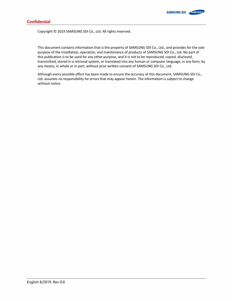
Important Safety Instructions
Read and follow these instructions!
The following precautions are intended to ensure your safety and prevent property damage. Before installing this product, be sure to read all safety instructions in this document for proper installation.
DANGER
Failure to comply with the instructions with this symbol may result in a serious accident, causing death or a severe injury.
WARNING
Failure to comply with the instructions with this symbol may result in a serious accident, causing a severe injury.
CAUTION
Failure to comply with the instructions with this symbol may result in minor or moderate injury.
NOTICE
Provides information considered important but not hazard-related. The information relates to property damage.
Important
Indicates valuable tips for optimal installation and operation of the product.

Important Safety Instructions Confidential
ii English 8/2019. Rev 0.0
General Instructions
Please be aware that a battery presents a risk of electrical shock including high short-circuit current. Follow all safety precautions while operating the batteries.
Remove watches, rings, and other metallic accessories. Use tools with insulated handles in order to avoid inadvertent short circuits. Wear rubber gloves and safety boots. Do not put tools or any metal parts on the top of the batteries. Disconnect charging source and load before connecting or disconnecting terminals. Use proper lifting means when moving batteries and wear all appropriate safety clothing and equipment. Batteries must be handled, transported and recycled or discarded in accordance with federal, state, and local
regulations. Do not dispose of the batteries in a fire because they can explode. Do not open or mutilate the batteries. Only authorized, trained technicians should perform annual preventive maintenance. Only qualified personnel who are familiar with the batteries and safety precautions should perform
installation or maintenance of the battery. Do not allow unauthorized personnel to contact the batteries.
Safety Precautions
The following precautions provide general safety guidelines that should be followed when working with or near the Energy Storage System (ESS). Complete safety parameters and procedures are site-specific and should be developed by the customer for the installation site.
Review and refer to all safety warnings and cautions in this manual before installation. Build a clear, permanent, restricted access area around the system. Only authorized, adequately trained electrical operators should be able to access the system.
The interior design of this equipment must be considered a “no-go area except for non-qualified personnel who are familiar with the batteries and safety precautions,” depending on the location. Consult local codes and applicable rules and regulations to determine permit requirements. If required, mark enclosures appropriately before beginning work.
Confidential Important Safety Instructions
English 8/2019. Rev 0.0 iii
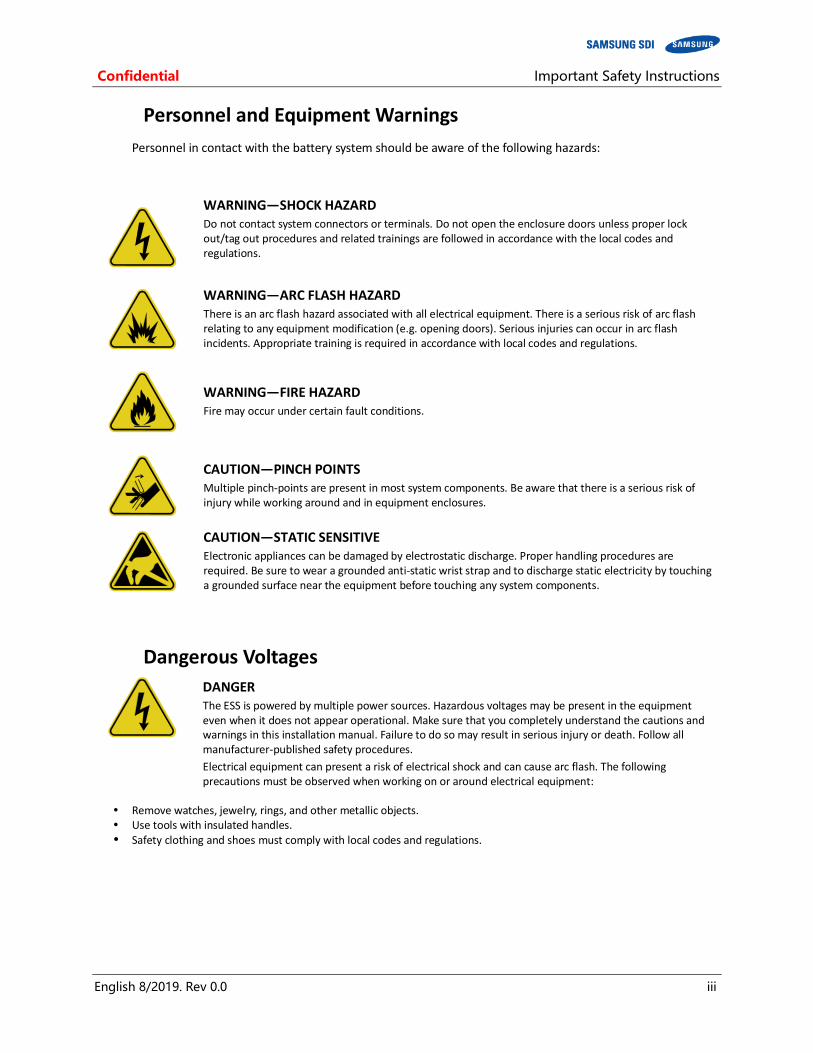
Personnel and Equipment Warnings
Personnel in contact with the battery system should be aware of the following hazards:
WARNING—SHOCK HAZARD Do not contact system connectors or terminals. Do not open the enclosure doors unless proper lock out/tag out procedures and related trainings are followed in accordance with the local codes and regulations.
WARNING—ARC FLASH HAZARD There is an arc flash hazard associated with all electrical equipment. There is a serious risk of arc flash relating to any equipment modification (e.g. opening doors). Serious injuries can occur in arc flash incidents. Appropriate training is required in accordance with local codes and regulations.
WARNING—FIRE HAZARD Fire may occur under certain fault conditions.
CAUTION—PINCH POINTS Multiple pinch-points are present in most system components. Be aware that there is a serious risk of injury while working around and in equipment enclosures.
CAUTION—STATIC SENSITIVE Electronic appliances can be damaged by electrostatic discharge. Proper handling procedures are required. Be sure to wear a grounded anti-static wrist strap and to discharge static electricity by touching a grounded surface near the equipment before touching any system components.
Dangerous Voltages
DANGER The ESS is powered by multiple power sources. Hazardous voltages may be present in the equipment even when it does not appear operational. Make sure that you completely understand the cautions and warnings in this installation manual. Failure to do so may result in serious injury or death. Follow all manufacturer-published safety procedures.
Electrical equipment can present a risk of electrical shock and can cause arc flash. The following precautions must be observed when working on or around electrical equipment:
Remove watches, jewelry, rings, and other metallic objects. Use tools with insulated handles. Safety clothing and shoes must comply with local codes and regulations.
Important Safety Instructions Confidential
iv English 8/2019. Rev 0.0
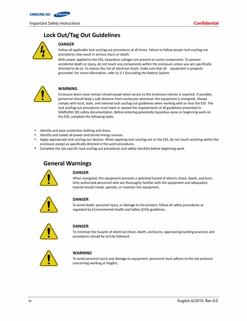
Lock Out/Tag Out Guidelines
DANGER Follow all applicable lock out/tag out procedures at all times. Failure to follow proper lock out/tag out procedures may result in serious injury or death.
With power applied to the ESS, hazardous voltages are present on some components. To prevent accidental death or injury, do not touch any components within the enclosure unless you are specifically directed to do so. To reduce the risk of electrical shock, make sure that all equipment is properly grounded. For more information, refer to 3.1 Grounding the Battery System
WARNING Enclosure doors must remain closed except when access to the enclosure interior is required. If possible, personnel should keep a safe distance from enclosures whenever the equipment is energized. Always comply with local, state, and national lock out/tag out guidelines when working with or near the ESS. The lock out/tag out procedures must meet or exceed the requirements of all guidelines presented in SAMSUNG SDI safety documentation. Before entering potentially hazardous areas or beginning work on the ESS, complete the following tasks:
Identify and wear protective clothing and shoes. Identify and isolate all power and stored energy sources. Apply appropriate lock out/tag out devices. When applying lock out/tag out to the ESS, do not touch anything within the
enclosure except as specifically directed in the work procedures. Complete the site-specific lock out/tag out procedures and safety checklist before beginning work.
General Warnings
DANGER When energized, this equipment presents a potential hazard of electric shock, death, and burn. Only authorized personnel who are thoroughly familiar with the equipment and adequately trained should install, operate, or maintain this equipment.
DANGER To avoid death, personal injury, or damage to the product, follow all safety procedures as regulated by Environmental Health and Safety (EHS) guidelines.
DANGER To minimize the hazards of electrical shock, death, and burns, approved grounding practices and procedures should be strictly followed.
WARNING To avoid personal injury and damage to equipment, personnel must adhere to the site protocol concerning working at heights.
Confidential Important Safety Instructions
English 8/2019. Rev 0.0 v
WARNING To avoid personal injury or equipment damage caused by equipment malfunction, only adequately trained personnel should modify any programmable machine.
WARNING Always ensure that applicable standards and regulations are followed and only properly certified equipment is used as a critical component of a safety system. Never assume that a safety-critical control loop is functioning correctly.

Important Safety Instructions Confidential
vi English 8/2019. Rev 0.0
Table of Contents Confidential
English 8/2019. Rev 0.0 i
Table of Contents
Important Safety Instructions ................................................................................................................. i
General Instructions ....................................................................................................................................... ii Safety Precautions ......................................................................................................................................... ii Personnel and Equipment Warnings ...............................................................................................................iii Dangerous Voltages .......................................................................................................................................iii Lock Out/Tag Out Guidelines ..........................................................................................................................iv General Warnings ..........................................................................................................................................iv
Table of Contents ................................................................................................................................... i
Tables ................................................................................................................................................... iii
Figures .................................................................................................................................................. iv
1. About this Manual ............................................................................................................................ 1
1.1 Purpose................................................................................................................................................ 1 1.2 Target Audience.................................................................................................................................... 1 1.3 Organization ......................................................................................................................................... 1 1.4 Revision History .................................................................................................................................... 2 1.5 Acronyms and Abbreviations................................................................................................................. 3
2. Product Description .......................................................................................................................... 4
2.1 Major Components ............................................................................................................................... 4
2.1.1 Battery Module (Type A / Type B) ............................................................................................ 5
2.1.2 SMU (String Management Unit) .............................................................................................. 7
2.1.3 SMPS Assembly (Type A / Type B) .......................................................................................... 10
2.1.4 Rack Frame........................................................................................................................... 17
3. Installing the Product ...................................................................................................................... 18
3.1 Grounding the Battery System ............................................................................................................ 18 3.2 Arc Flash Calculations ......................................................................................................................... 19 3.3 Installation Procedure ......................................................................................................................... 20 3.4 Preparation Stage—Procedure ............................................................................................................ 22 3.5 Preparation Stage—Unpacking............................................................................................................ 23 3.6 Preparation Stage—Ground Wire and Tools ......................................................................................... 24
3.6.1 Ground Wires ....................................................................................................................... 24
3.6.2 Ground Wire Fasteners ......................................................................................................... 24
3.6.3 Rack Fasteners (Anchors) ...................................................................................................... 24
3.6.4 Multiple Rack Fasteners ........................................................................................................ 24
3.7 Preparation Stage—Recommended Tools/Instruments ........................................................................ 25 3.8 Preparation Stage—Visual Inspection .................................................................................................. 27
3.8.1 Inspection of the Rack Frame ................................................................................................ 27
3.8.2 Inspection of the Modules .................................................................................................... 27
3.8.3 Inspecting the SMU .............................................................................................................. 27
3.8.4 Inspecting the SMPS assembly .............................................................................................. 28
3.9 Rack Anchoring Stage ......................................................................................................................... 29 3.10 Rack Installation Stage ........................................................................................................................ 38
3.10.1 Front Door Removal .............................................................................................................. 39
3.10.2 SMU and SMPS Assembly Installation .................................................................................... 41
Confidential Table of Contents
ii English 8/2019. Rev 0.0
3.10.3 Battery Module Installation ................................................................................................... 45
3.10.4 Fuse-Busbar Assembly .......................................................................................................... 48
3.10.5 Busbar Installation ................................................................................................................ 51
3.10.6 Module and SMU Signal Cable Connection ............................................................................ 85
3.10.7 SMPS Assembly and SMU Power Cable Connection ............................................................... 97
3.10.8 SMPS Assembly and SMU Signal Cable Connection ................................................................ 98
3.10.9 SMPS Assembly AC Input Connection .................................................................................. 100
3.10.10 DC Link Cable Connection ................................................................................................... 106
3.10.11 AC Input Commissioning ..................................................................................................... 109
3.10.12 BMS Configuration .............................................................................................................. 110
3.10.13 Communication Check ........................................................................................................ 125
3.10.14 Reinstall the Front Door ...................................................................................................... 132
3.10.15 Reinstall the Front Panel ..................................................................................................... 133
3.10.16 Switching on the MCCB ....................................................................................................... 134
Table of Contents Confidential
English 8/2019. Rev 0.0 iii
Tables
Table 2-1: Extra Auxiliary Breaker Switch Connector Description ................................................................................ 8 Table 2-2: Terminal Block Description ........................................................................................................................ 9 Table 2-3: RS485 Connector Description .................................................................................................................. 13 Table 2-4: TCP/IP Connector Description ................................................................................................................. 13 Table 2-5: Dry Contact Connector Description ......................................................................................................... 14 Table 2-6: AC Terminal Description (3 phase) ........................................................................................................... 14 Table 2-7: AC Terminal Description (1 phase) ........................................................................................................... 14 Table 2-8: Dry Contact Operation (Customer ID = 0)................................................................................................. 15 Table 2-9: Dry Contact Operation (Customer ID = 1)................................................................................................. 15 Table 2-10: Dry Contact Operation (Customer ID = 2) ............................................................................................... 15 Table 3-1: Estimated time for installation (based on 136S 3P installation) ................................................................ 21 Table 3-2: Parts for 136S 3P Rack ............................................................................................................................ 23 Table 3-3: Ground Wire Specifications ..................................................................................................................... 24 Table 3-4: Ground Wire Fastener Specification ........................................................................................................ 24 Table 3-5: Rack Fastener Specifications ................................................................................................................... 24 Table 3-6: Rack Fastener Specifications (Side by side) .............................................................................................. 24 Table 3-7: Recommended Tools and Instruments .................................................................................................... 25 Table 3-8: Module Voltage and Internal Impedance ................................................................................................. 27 Table 3-9: Rack Clearance Distances ........................................................................................................................ 29 Table 3-10: Required Items for BMS Configuration ................................................................................................ 110 Table 3-11: Rack BMS Configuration Cable Pin Map ............................................................................................... 111 Table 3-12: System BMS Configuration Cable Pin Map ........................................................................................... 112 Table 3-13: System BMS Communication Cable Pin Map ........................................................................................ 113

Confidential Table of Contents
iv English 8/2019. Rev 0.0
Figures
Figure 2-1: Battery Module Type A ......................................................................................................................................... 5 Figure 2-2: Battery Module Type B ......................................................................................................................................... 6 Figure 2-3: SMU ........................................................................................................................................................................ 7 Figure 2-4: Auxiliary Breaker Switch ....................................................................................................................................... 8 Figure 2-5: Terminal Block Isometric View ............................................................................................................................. 8 Figure 2-6: Terminal Block Front / Top View (Cover Opened/Closed) ................................................................................. 9 Figure 2-7: SMPS Assembly Type A ....................................................................................................................................... 10 Figure 2-8: SMPS Assembly Type B ....................................................................................................................................... 11 Figure 2-9: Front View of SMPS Assembly Type A, 3-Phase Input ...................................................................................... 11 Figure 2-10: Front View of SMPS Assembly Type A, 1-Phase Input .................................................................................... 11 Figure 2-11: SMPS Assembly Type A – System BMS Connections ...................................................................................... 11 Figure 2-12: Front View of SMPS Assembly Type B, 1-Phase Input .................................................................................... 12 Figure 2-13: Rack Frame ........................................................................................................................................................ 17 Figure 3-1: Installation Procedure ......................................................................................................................................... 20 Figure 3-2: Clearance Distance for Single Rack Frame......................................................................................................... 30 Figure 3-3: Clearance Distance for Multiple Rack Frames Installed Side-by-Side.............................................................. 30 Figure 3-4: Clearance Distance for Multiple Rack Frames Installed Side-by-Side and Rear-to-Rear................................ 31 Figure 3-5: Front panel screws (eight) .................................................................................................................................. 31 Figure 3-6: Front panel hooks (four) ..................................................................................................................................... 32 Figure 3-7: Side panel screws (six) ........................................................................................................................................ 32 Figure 3-8: Side panel hooks (four) ....................................................................................................................................... 33 Figure 3-9: Rear panel screws (eight).................................................................................................................................... 33 Figure 3-10: Rear panel hooks (four) .................................................................................................................................... 34 Figure 3-11: Rack Anchoring Points (4 EA) ........................................................................................................................... 34 Figure 3-12: Holes on the sides of the rack (six) .................................................................................................................. 35 Figure 3-13: Reattaching the Side Panels (four hooks and six screws for each panel) ..................................................... 36 Figure 3-14: Reattaching the Rear Panels ............................................................................................................................. 37 Figure 3-15: Front door ajar................................................................................................................................................... 39 Figure 3-16: Removing the earth cable ................................................................................................................................. 39 Figure 3-17: Removing the front door .................................................................................................................................. 40 Figure 3-18: All doors and front panels removed. ............................................................................................................... 40 Figure 3-19: Inserting SMU .................................................................................................................................................... 41 Figure 3-20: Attaching a SMU to a Rack Frame .................................................................................................................... 41 Figure 3-21: Ground Cable Connection to the SMU ............................................................................................................ 42 Figure 3-22: Inserting SMPS Assembly .................................................................................................................................. 43 Figure 3-23: Attaching the SMPS Assembly .......................................................................................................................... 43 Figure 3-24: Ground Cable Connection to the SMPS Assembly .......................................................................................... 44 Figure 3-25: Insertion of Modules on the Ninth Shelf from the Bottom ............................................................................ 45 Figure 3-26: Battery Module Arrangement on the Eighth Shelf ......................................................................................... 46 Figure 3-27: Battery Module Arrangement .......................................................................................................................... 46 Figure 3-28 : Module Number ............................................................................................................................................... 47 Figure 3-29: Insertion of modules on 1st shelf..................................................................................................................... 47 Figure 3-30: Rack Fuse Busbar Assembly .............................................................................................................................. 48 Figure 3-31: Rack Fuse Busbar Assembly (Fuse Cover) ........................................................................................................ 48 Figure 3-32: Fuse Busbar Left Assembly ............................................................................................................................... 49 Figure 3-33: Fuse Busbar Left Assembly (Fuse Cover) ......................................................................................................... 49 Figure 3-34: Fuse Busbar Right Assembly ............................................................................................................................. 50 Figure 3-35: Fuse Busbar Right Assembly (Fuse Cover) ....................................................................................................... 50 Figure 3-36: Removing the Module #1’s Cover and SMU B- Terminal Cover .................................................................... 52 Figure 3-37: Connect SMU B- and Module #1 B- ................................................................................................................. 52

Table of Contents Confidential
English 8/2019. Rev 0.0 v
Figure 3-38: Restore SMU’s B- Terminal ............................................................................................................................... 53 Figure 3-39: Remove Battery Module #2’s Front Cover ...................................................................................................... 53 Figure 3-40: Connect Battery Module #1 B+ and Battery Module #2 B-............................................................................ 54 Figure 3-41: Reattach Battery Module #1’s Front Cover ..................................................................................................... 54 Figure 3-42: Remove Battery Module #2’s Front Cover ...................................................................................................... 55 Figure 3-43: Connect Battery Module #2 B+ and Battery Module #3 B-............................................................................ 55 Figure 3-44: Reattach Battery Module #2’s Front Cover ..................................................................................................... 56 Figure 3-45: Remove Battery Module #4’s Front Cover ...................................................................................................... 56 Figure 3-46: Connect Battery Module #3 B+ and Module #4 B-. ........................................................................................ 57 Figure 3-47: Reattach Battery Module #3’s Front Cover ..................................................................................................... 58 Figure 3-48: Remove Battery Module #5’s Front Cover ...................................................................................................... 58 Figure 3-49: Connect Battery Module #4 B+ and Battery Module #5 B-............................................................................ 59 Figure 3-50: Reattach Battery Module #4’s Front Cover ..................................................................................................... 60 Figure 3-51: Remove Battery Module #6’s Front Cover ...................................................................................................... 60 Figure 3-52: Connect Battery Module #5 B+ and Battery Module #6 B-............................................................................ 61 Figure 3-53: Reattach Battery Module #5’s Front Cover ..................................................................................................... 62 Figure 3-54: Remove Battery Module #7’s Front Cover ...................................................................................................... 62 Figure 3-55: Connect Battery Module #6 B+ and Battery Module #7 B- ............................................................................ 63 Figure 3-56: Reattach Battery Module #6’s Front Cover ..................................................................................................... 64 Figure 3-57: Remove Battery Module #8’s Front Cover ...................................................................................................... 64 Figure 3-58: Connect Battery Module #7 B+ and Battery Module #8 B- ............................................................................ 65 Figure 3-59: Reattach Battery Modules #7’s Front Cover ................................................................................................... 65 Figure 3-60: Remove Battery Modules #9’s Front Cover .................................................................................................... 66 Figure 3-61: Connect Battery Module #8 B+ and Battery Module #9 B-............................................................................ 67 Figure 3-62: Reattach Battery Modules #8’s Front Cover ................................................................................................... 67 Figure 3-63: Remove Battery Modules #10’s Front Cover .................................................................................................. 68 Figure 3-64 Connect Battery Module #9 B+ and Battery Module #10 B-. .......................................................................... 68 Figure 3-65: Reattach Battery Module #9’s Front Cover ..................................................................................................... 69 Figure 3-66: Remove Battery Module #11’s Front Cover .................................................................................................... 69 Figure 3-67: Connect Battery Module #10 B+ and Battery Module #11 B-. ...................................................................... 70 Figure 3-68: Reattach Battery Module #10’s Front Cover ................................................................................................... 71 Figure 3-69: Remove Battery Module #12’s Front Cover .................................................................................................... 71 Figure 3-70: Connect Battery Module #11 B+ and Battery Module #12 B-. ...................................................................... 72 Figure 3-71: Reattach Module #11’s Front Cover ................................................................................................................ 73 Figure 3-72: Remove Module #13’s Front Cover ................................................................................................................. 73 Figure 3-73: Connect Battery Module #12B+ and Battery Module #13 B-. ....................................................................... 74 Figure 3-74: Reattach Module #12’s Front Cover ................................................................................................................ 75 Figure 3-75: Remove Battery Module #14’s Front Cover .................................................................................................... 75 Figure 3-76: Connect Battery Module #13 B+ and Battery Module #14 B-. ...................................................................... 76 Figure 3-77: Reattach Battery Module #13’s Front Cover ................................................................................................... 77 Figure 3-78: Remove Battery Module #15’s Front Cover .................................................................................................... 77 Figure 3-79: Connect Battery Module #14 B+ and Battery Module #15 B-. ...................................................................... 78 Figure 3-80: Reattach Battery Module #14’s Front Cover ................................................................................................... 79 Figure 3-81: Remove Battery Module #16’s Front Cover .................................................................................................... 79 Figure 3-82: Connect Battery Module #15 B+ and Battery Module #16 B-. ...................................................................... 80 Figure 3-83: Reattach Battery Module #15’s Front Cover ................................................................................................... 81 Figure 3-84: Remove Battery Module #17’s Front Cover .................................................................................................... 81 Figure 3-85: Connect Battery Module #16 B+ and Battery Module #17 B-. ...................................................................... 82 Figure 3-86: Reattach Battery Module #15’s Front Cover ................................................................................................... 83 Figure 3-87: Remove SMU B+ Terminal Cover ..................................................................................................................... 83 Figure 3-88: Connect SMU B+ and Module #17 B+. ............................................................................................................. 84 Figure 3-89: Reattach Battery Module #17’s Front Cover and SMU B+ Terminal Cover .................................................. 84 Figure 3-90: SMU to Module #1 Signal Cable ....................................................................................................................... 85

Confidential Table of Contents
vi English 8/2019. Rev 0.0
Figure 3-91: Module #1 to Module #2 Signal Cabling .......................................................................................................... 86 Figure 3-92: Module #2 to Module #3 Signal Cabling .......................................................................................................... 86 Figure 3-93: Module #3 to Module #4 Signal Cabling .......................................................................................................... 87 Figure 3-94: Module #4 to Module #5 Signal Cabling .......................................................................................................... 87 Figure 3-95: Module #5 to Module #6 Signal Cabling .......................................................................................................... 88 Figure 3-96: Module #6 to Module #7 Signal Cabling .......................................................................................................... 88 Figure 3-97: Module #7 to Module #8 Signal Cabling .......................................................................................................... 89 Figure 3-98: Module #8 to Module #9 Signal Cabling .......................................................................................................... 89 Figure 3-99: Module #9 to Module #10 Signal Cabling........................................................................................................ 90 Figure 3-100: Module #10 to Module #11 Signal Cabling ................................................................................................... 90 Figure 3-101: Module #11 to Module #12 Signal Cabling ................................................................................................... 91 Figure 3-102: Module #12 to Module #13 Signal Cabling ................................................................................................... 91 Figure 3-103: Module #13 to Module #14 Signal Cabling ................................................................................................... 92 Figure 3-104: Module #14 to Module #15 Signal Cabling ................................................................................................... 92 Figure 3-105: Module #15 to Module #16 Signal Cabling ................................................................................................... 93 Figure 3-106: Module #16 to Module #17 Signal Cabling ................................................................................................... 93 Figure 3-107: Pre-Punched Hole for Signal Cable ................................................................................................................ 94 Figure 3-108: Signal Cabling Examples of Left Alignment of SMU ...................................................................................... 95 Figure 3-109: Termination Resistor Setting for Last SMU ................................................................................................... 96 Figure 3-110: DC Power Cables from SMPS Assembly 3 Phase Type A to SMU................................................................. 97 Figure 3-111: DC Power Cables from SMPS Assembly 3 Phase Type B to SMU ................................................................. 97 Figure 3-112: CAN Signal Cable Connection from SMPS Assembly 3 Phase Type A to SMU ............................................ 98 Figure 3-113: TCP/IP Cable Connection to SMPS Assembly ................................................................................................ 98 Figure 3-114: Dry Contact Cable Connection to SMPS Assembly ....................................................................................... 99 Figure 3-115: MCCB Extra Auxiliary Connection .................................................................................................................. 99 Figure 3-116: AC Input Terminals of SMPS Assembly 3 Phase Type A ............................................................................ 100 Figure 3-117: AC Input Terminals of SMPS Assembly 3 Phase Type B............................................................................. 100 Figure 3-118: AC Input Terminals of SMPS Assembly 1 Phase Type A ............................................................................ 101 Figure 3-119: AC Input Terminals of SMPS Assembly 1 Phase Type B............................................................................. 101 Figure 3-120: SMPS Assembly 3 Phase Type A - AC Input Terminals with Cables Attached .......................................... 102 Figure 3-121: SMPS Assembly 3 Phase Type B - AC Input Terminals with Cables Attached .......................................... 102 Figure 3-122: SMPS Assembly 1 Phase Type A - AC Input Terminals with Cables Attached .......................................... 103 Figure 3-123: SMPS Assembly 1 Phase Type B - AC Input Terminals with Cables Attached .......................................... 103 Figure 3-124: AC Input Terminals of SMPS Assembly 3 Phase Type A ............................................................................ 103 Figure 3-125: AC Input Terminals of SMPS Assembly 3 Phase Type B............................................................................. 104 Figure 3-126: AC Input Terminals of SMPS Assembly 1 Phase Type A ............................................................................ 104 Figure 3-127: AC Input Terminals of SMPS Assembly 1 Phase Type B............................................................................. 105 Figure 3-128: Grounding Points (2 EA)............................................................................................................................... 106 Figure 3-129: Connecting the DC Link High Current Terminals ........................................................................................ 107 Figure 3-130: Rack BMS Configuration Cable Pin Map ..................................................................................................... 111 Figure 3-131: System BMS Configuration Cable Pin Map ................................................................................................. 112 Figure 3-132: System BMS Communication Cable Pin Map ............................................................................................. 113 Figure 3-133: BATTMON Splash Window .......................................................................................................................... 115 Figure 3-134: Installer Access Password ............................................................................................................................ 115 Figure 3-135: BATTMON Splash Window .......................................................................................................................... 116 Figure 3-136: Warning Pop-up Window ............................................................................................................................ 116 Figure 3-137: Selecting System BMS Configuration Parameter File ................................................................................ 116 Figure 3-138: BATTMON Splash Window : Warning Pop-up Window............................................................................. 117 Figure 3-139: Warning Pop-up Window ............................................................................................................................ 117 Figure 3-140: Selecting Rack BMS Configuration Parameter File .................................................................................... 117 Figure 3-141: Cable Connections for Rack BMS Configuration ........................................................................................ 118 Figure 3-142: Rack BMS CAN ID Numbers for a Multiple Rack System ........................................................................... 118 Figure 3-143: Rack BMS termination switch and CAN cable connection ........................................................................ 119

Table of Contents Confidential
English 8/2019. Rev 0.0 vii
Figure 3-144: BATTMON Icon ............................................................................................................................................. 119 Figure 3-145: BATTMON Splash Window .......................................................................................................................... 120 Figure 3-146: Rack BMS - CONFIG connection window .................................................................................................... 120 Figure 3-147: Rack BMS Config Setting window ............................................................................................................... 121 Figure 3-148: Cable Connections for System BMS Configuration .................................................................................... 122 Figure 3-149: BATTMON Icon ............................................................................................................................................. 122 Figure 3-150: BATTMON Splash Window .......................................................................................................................... 123 Figure 3-151: SYSTEM BMS – CONFIG connection window ............................................................................................. 123 Figure 3-152: System BMS Install Setting Window ........................................................................................................... 124 Figure 3-153: Open “Network” ........................................................................................................................................... 125 Figure 3-154: Open “Network and Sharing Center” ......................................................................................................... 126 Figure 3-155: Open “Change adapter settings” ................................................................................................................ 126 Figure 3-156: Open “Properties” for “Local Area Connection” ........................................................................................ 127 Figure 3-157: Open Properties for “Internet Protocol Version 4 (TCP/IPv4)” ................................................................ 127 Figure 3-158: Setting the Computer’s IP address.............................................................................................................. 128 Figure 3-159: BATTMON Icon ............................................................................................................................................. 129 Figure 3-160: BATTMON Splash Window .......................................................................................................................... 129 Figure 3-161: System BMS – Monitor Setting ................................................................................................................... 129 Figure 3-162: System and Rack Information ..................................................................................................................... 130 Figure 3-163: Log setting..................................................................................................................................................... 130 Figure 3-164: Cell Information............................................................................................................................................ 131 Figure 3-165: Reattaching the Front Door ......................................................................................................................... 132 Figure 3-166: Reattaching the earth cable. ....................................................................................................................... 132 Figure 3-167: Front panel hooks (four) .............................................................................................................................. 133 Figure 3-168: Front panel screws (eight) ........................................................................................................................... 133 Figure 3-169: MCCB Handle in Trip Position ..................................................................................................................... 134 Figure 3-170: MCCB Handle in Off Position ....................................................................................................................... 134 Figure 3-171: MCCB Handle in On Position ....................................................................................................................... 134

Confidential Table of Contents
viii English 8/2019. Rev 0.0
Confidential 1. About this Manual
English 8/2019. Rev 0.0 1
1. About this Manual
To make sure that you understand the proper procedures for safe operation, this section briefly describes the purpose, audience, organization, revision history, and acronyms and abbreviations.
1.1 Purpose
The purpose of this manual is to provide information for the safe and successful installation of the product
The instructions in this manual are based on assembly of a three-cabinet system. Other configurations are possible and the instructions can be reduced or expanded to accommodate installation of those systems.
1.2 Target Audience
This installation manual is intended for system administrators and operators who install and configure the product.
1.3 Organization
This manual is composed of the following chapters:
Chapter 1, “About this Manual,” outlines this document. Chapter 2, “Product Description,” describes the major components of the product. Chapter 3, “Installing the Product,” explains how to install the product.
1. About this Manual Confidential
2 English 8/2019. Rev 0.0
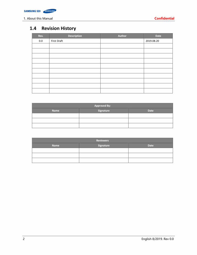
1.4 Revision History
Rev. Description Author Date
0.0 First Draft 2019.08.20
Approved By:
Name Signature Date
Reviewers
Name Signature Date

Confidential 1. About this Manual
English 8/2019. Rev 0.0 3
1.5 Acronyms and Abbreviations
The following acronyms and abbreviations are used in this manual.
Abbreviations Full Name
AED Automated External Defibrillator
BMS Battery Management System
EHS Environmental Health and Safety
ESS Energy Storage System
LOTO LOCK OUT/TAG OUT
OT Overtemperature OVP Overvoltage Protection
PCS Power Conversion System
SMU String Management Unit
SMPS Switched Mode Power Supply
SOC State Of Charge
SOH State Of Health
SG Switchgear
UT Undertemperature
UVP Undervoltage Protection
UPS Uninterruptible Power Supply

2. Product Description Confidential
4 English 8/2019. Rev 0.0
2. Product Description
Check the components for installation. For more information, please refer to the product specification.
2.1 Major Components
This product has the following components:
Battery Module (Type A / Type B) SMU Rack BMS (Embedded in SMU) Rack Frame SMPS Assembly (Type A / Type B) System BMS (Embedded in SMPS Assembly Type A)
Refer to the “Product Specification” document for detailed specifications of the components.
Confidential 2. Product Description
English 8/2019. Rev 0.0 5
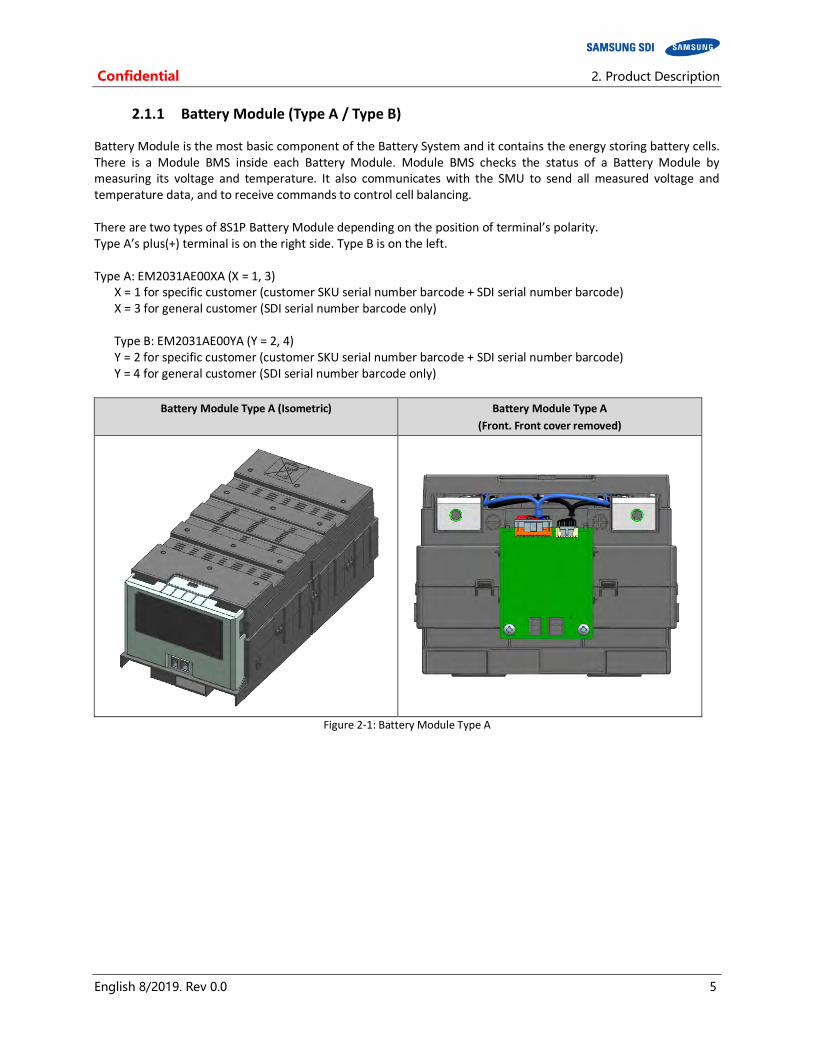
2.1.1 Battery Module (Type A / Type B)
Battery Module is the most basic component of the Battery System and it contains the energy storing battery cells. There is a Module BMS inside each Battery Module. Module BMS checks the status of a Battery Module by measuring its voltage and temperature. It also communicates with the SMU to send all measured voltage and temperature data, and to receive commands to control cell balancing. There are two types of 8S1P Battery Module depending on the position of terminal’s polarity. Type A’s plus(+) terminal is on the right side. Type B is on the left. Type A: EM2031AE00XA (X = 1, 3) X = 1 for specific customer (customer SKU serial number barcode + SDI serial number barcode) X = 3 for general customer (SDI serial number barcode only) Type B: EM2031AE00YA (Y = 2, 4)
Y = 2 for specific customer (customer SKU serial number barcode + SDI serial number barcode) Y = 4 for general customer (SDI serial number barcode only)
Battery Module Type A (Isometric) Battery Module Type A
(Front. Front cover removed)
Figure 2-1: Battery Module Type A

2. Product Description Confidential
6 English 8/2019. Rev 0.0
Battery Module Type B (Isometric) Battery Module Type B
(Front. Front cover removed)
Figure 2-2: Battery Module Type B
Confidential 2. Product Description
English 8/2019. Rev 0.0 7
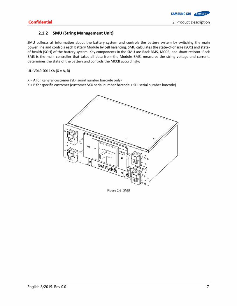
2.1.2 SMU (String Management Unit)
SMU collects all information about the battery system and controls the battery system by switching the main power line and controls each Battery Module by cell balancing. SMU calculates the state-of-charge (SOC) and state-of-health (SOH) of the battery system. Key components in the SMU are Rack BMS, MCCB, and shunt resistor. Rack BMS is the main controller that takes all data from the Module BMS, measures the string voltage and current, determines the state of the battery and controls the MCCB accordingly. UL: V049-0011XA (X = A, B) X = A for general customer (SDI serial number barcode only) X = B for specific customer (customer SKU serial number barcode + SDI serial number barcode)
Figure 2-3: SMU

2. Product Description Confidential
8 English 8/2019. Rev 0.0
SMU provides an auxiliary breaker switch that can be connected to the building monitoring system.
Figure 2-4: Auxiliary Breaker Switch
Table 2-1: Extra Auxiliary Breaker Switch Connector Description
Item Part Name Description
Connector J21SPM-04V-KX -
Harness Housing J21SF-04V-KX-L -
Harness Terminal SJ2F-01GF-P1.0 AWG 20~24
Pin No. Pin Name Function
1 Normal Open
2 Common
3 Normal Close
4 -
P+ and P- terminal blocks connect to the DC link from the UPS. Cable and lug terminals should be selected according to the terminal block’s size and material.
Figure 2-5: Terminal Block Isometric View
Confidential 2. Product Description
English 8/2019. Rev 0.0 9
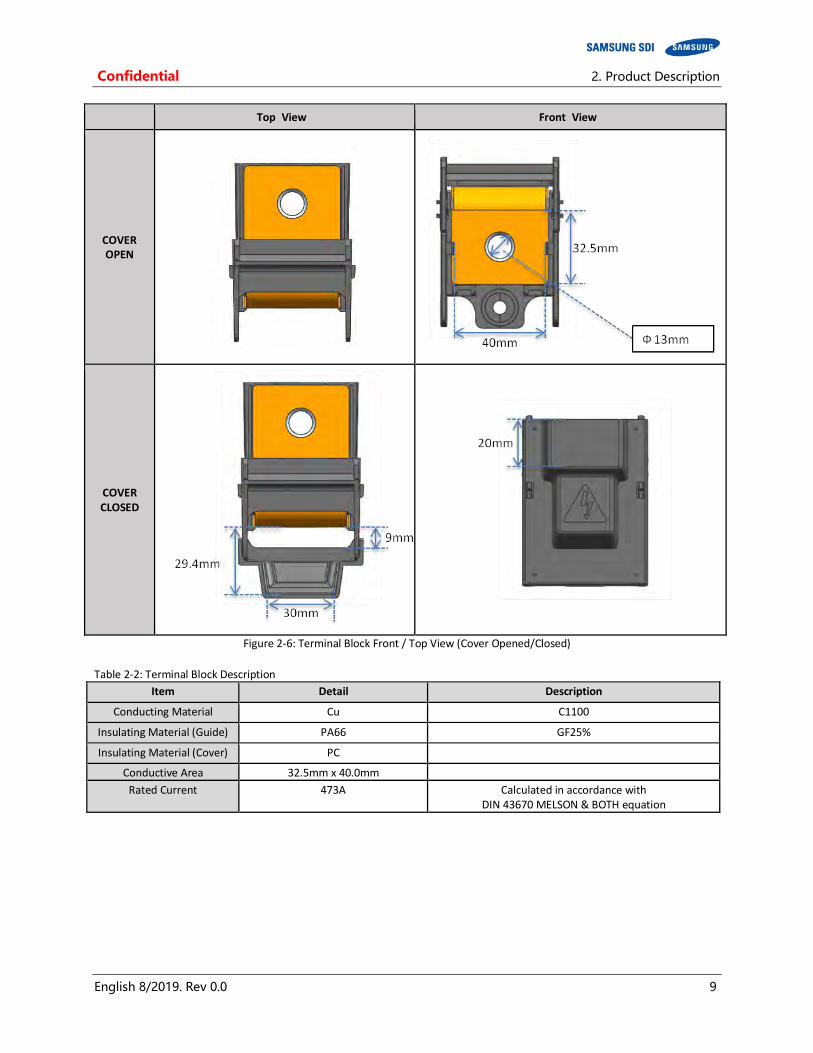
Top View Front View
COVER OPEN
COVER CLOSED
Figure 2-6: Terminal Block Front / Top View (Cover Opened/Closed)
Table 2-2: Terminal Block Description
Item Detail Description
Conducting Material Cu C1100
Insulating Material (Guide) PA66 GF25%
Insulating Material (Cover) PC
Conductive Area 32.5mm x 40.0mm
Rated Current 473A Calculated in accordance with DIN 43670 MELSON & BOTH equation
2. Product Description Confidential
10 English 8/2019. Rev 0.0
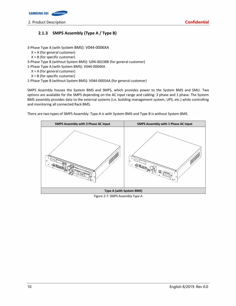
2.1.3 SMPS Assembly (Type A / Type B)
3-Phase Type A (with System BMS): V044-0006XA X = A (for general customer) X = B (for specific customer)
3-Phase Type B (without System BMS): SJ94-00238B (for general customer) 1-Phase Type A (with System BMS): V044-0004XA
X = A (for general customer) X = B (for specific customer)
1-Phase Type B (without System BMS): V044-0005AA (for general customer) SMPS Assembly houses the System BMS and SMPS, which provides power to the System BMS and SMU. Two options are available for the SMPS depending on the AC input range and cabling: 3 phase and 1 phase. The System BMS assembly provides data to the external systems (i.e. building management system, UPS, etc.) while controlling and monitoring all connected Rack BMS. There are two types of SMPS Assembly: Type A is with System BMS and Type B is without System BMS.
SMPS Assembly with 3 Phase AC Input SMPS Assembly with 1 Phase AC Input
Type A (with System BMS)
Figure 2-7: SMPS Assembly Type A
Confidential 2. Product Description
English 8/2019. Rev 0.0 11
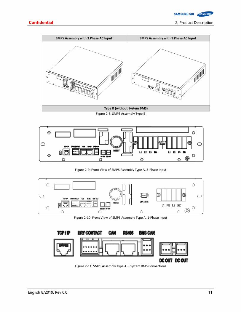
SMPS Assembly with 3 Phase AC Input SMPS Assembly with 1 Phase AC Input
Type B (without System BMS)
Figure 2-8: SMPS Assembly Type B
Figure 2-9: Front View of SMPS Assembly Type A, 3-Phase Input
Figure 2-10: Front View of SMPS Assembly Type A, 1-Phase Input
Figure 2-11: SMPS Assembly Type A – System BMS Connections

2. Product Description Confidential
12 English 8/2019. Rev 0.0
Figure 2-12: Front View of SMPS Assembly Type B, 1-Phase Input

Confidential 2. Product Description
English 8/2019. Rev 0.0 13
SMPS Assembly Type A provides RS485, TCP/IP and Dry contact. Table 2-3: RS485 Connector Description
Item Part Name Description
Connector IM25G-008-256 2 Port, RJ45
Harness Housing RJ45 -
Harness Terminal RJ45 -
Pin No. Pin Name Function
Left. 1
CAN port For debugging purpose only
Left. 2
Left. 3
Left. 4
Left. 5
Left. 6
Left. 7
Left. 8
Right. 1 RS485 A Rx+ (Short to Tx+ externally)
Right. 2 RS485 B Rx- (Short to Rx- externally)
Right. 3 RS485 Z Tx- (Short to Rx- externally)
Right. 4 -
Right. 5 -
Right. 6 RS485 Y Tx+
Right. 7 -
Right. 8 GND
Table 2-4: TCP/IP Connector Description
Item Part Name Description
Connector VS-08-BU-RJ45/LP-1 PHOENIX CONTACT
Harness Housing RJ45 -
Harness Terminal RJ45 -
Pin No. Pin Name Function
1 TX+ TCP/IP TX+
2 TX- TCP/IP TX-
3 RX+ TCP/IP RX+
4 GND GND
5 GND GND
6 RX- TCP/IP RX-
7 GND GND
8 GND GND
2. Product Description Confidential
14 English 8/2019. Rev 0.0
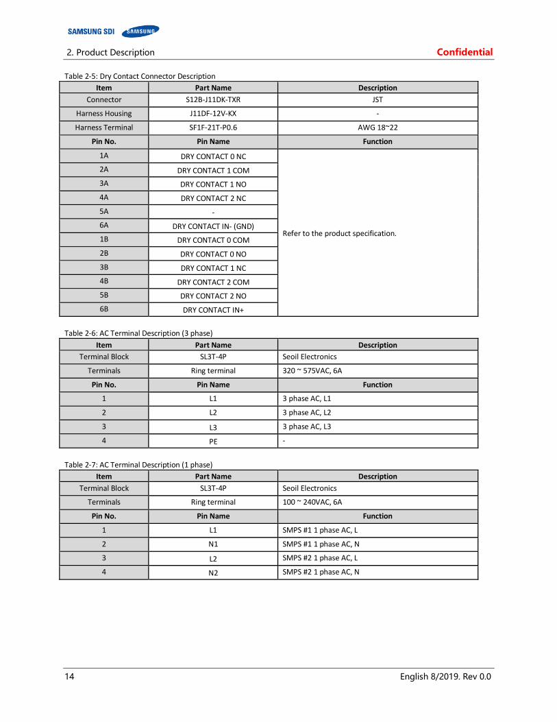
Table 2-5: Dry Contact Connector Description
Item Part Name Description
Connector S12B-J11DK-TXR JST
Harness Housing J11DF-12V-KX -
Harness Terminal SF1F-21T-P0.6 AWG 18~22
Pin No. Pin Name Function
1A DRY CONTACT 0 NC
Refer to the product specification.
2A DRY CONTACT 1 COM
3A DRY CONTACT 1 NO
4A DRY CONTACT 2 NC
5A -
6A DRY CONTACT IN- (GND)
1B DRY CONTACT 0 COM
2B DRY CONTACT 0 NO
3B DRY CONTACT 1 NC
4B DRY CONTACT 2 COM
5B DRY CONTACT 2 NO
6B DRY CONTACT IN+
Table 2-6: AC Terminal Description (3 phase)
Item Part Name Description
Terminal Block SL3T-4P Seoil Electronics
Terminals Ring terminal 320 ~ 575VAC, 6A
Pin No. Pin Name Function
1 L1 3 phase AC, L1
2 L2 3 phase AC, L2
3 L3 3 phase AC, L3
4 PE -
Table 2-7: AC Terminal Description (1 phase)
Item Part Name Description
Terminal Block SL3T-4P Seoil Electronics
Terminals Ring terminal 100 ~ 240VAC, 6A
Pin No. Pin Name Function
1 L1 SMPS #1 1 phase AC, L
2 N1 SMPS #1 1 phase AC, N
3 L2 SMPS #2 1 phase AC, L
4 N2 SMPS #2 1 phase AC, N

Confidential 2. Product Description
English 8/2019. Rev 0.0 15
Table 2-8: Dry Contact Operation (Customer ID = 0)
Pin No. Pin Name Function
B1 Major Common Over-Voltage Protection Under-Voltage Protection Over-Temperature Protection Over-Current Protection
A1 Major Normal Close
B2 Major Normal Open
A2 Minor Common Voltage Imbalance Error Voltage Sensing Error Under Temperature protection Temperature Imbalance Error
B3 Minor Normal Close
A3 Minor Normal Open
B4 Charge Common Charge Stop Set Condition 1. Overvoltage alarm(4.25V/Cell) 2. SOC 100% Charge Stop Release Condition 1. SOC < 97% or Discharge Current >│3A│
A4 Charge Normal Close
B5 Charge Normal Open
A5 Reserved
B6 Input Set Condition: UPS closes B6, A6 contacts for more than 3 second. Action : Battery MCCB Trip A6 GND
Table 2-9: Dry Contact Operation (Customer ID = 1)
Pin No. Pin Name Function
B1 Major Common Over-Voltage Protection Under-Voltage Protection Over-Temperature Protection Over-Current Protection
A1 Major Normal Close
B2 Major Normal Open
A2 Minor Common Voltage Imbalance Error Voltage Sensing Error Under Temperature protection Temperature Imbalance Error
B3 Minor Normal Close
A3 Minor Normal Open
B4 MCCB Status Common All MCCBs are off : 4A, 4B is closed One of MCCB is on : 5B, 4B is closed
A4 MCCB Status Normal Close
B5 MCCB Status Normal Open
A5 Reserved
B6 Input Set Condition: UPS opens B6, A6 contacts for more than 3 second. Action : Battery MCCB Trip A6 GND
Table 2-10: Dry Contact Operation (Customer ID = 2)
Pin No. Pin Name Function
B1 Discharge Prohibit Common
Undervoltage Protection Overtemperature Protection Discharge Overcurrent Protection
A1 Discharge Prohibit
Normal Close
B2 Discharge Prohibit
Normal Open
A2 Charge Prohibit Common Overvoltage Alarm, Overvoltage Protection Overtemperature Protection Charge Overcurrent Protection
B3 Charge Prohibit
Normal Close
A3 Charge Prohibit Normal Open
B4 MCCB Status Common All MCCBs are off : 4A, 4B is closed One of MCCB is on : 5B, 4B is closed
A4 MCCB Status Normal Close
B5 MCCB Status Normal Open
A5 Reserved
B6 Input Set Condition: UPS opens B6, A6 contacts for more than 1 second. Action : Battery MCCB Trip A6 GND
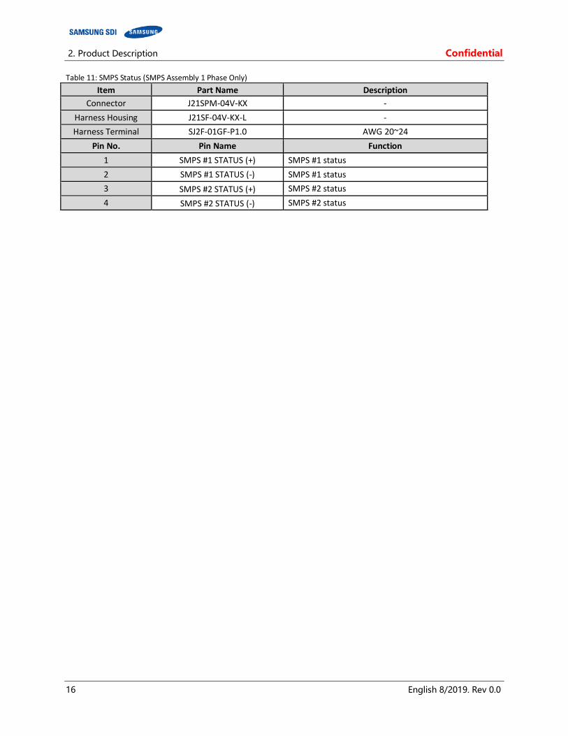
SMPS Assembly with 1 phase AC input has auxiliary connectors for the status of the SMPS.
2. Product Description Confidential
16 English 8/2019. Rev 0.0
Table 11: SMPS Status (SMPS Assembly 1 Phase Only)
Item Part Name Description
Connector J21SPM-04V-KX -
Harness Housing J21SF-04V-KX-L -
Harness Terminal SJ2F-01GF-P1.0 AWG 20~24
Pin No. Pin Name Function
1 SMPS #1 STATUS (+) SMPS #1 status
2 SMPS #1 STATUS (-) SMPS #1 status
3 SMPS #2 STATUS (+) SMPS #2 status
4 SMPS #2 STATUS (-) SMPS #2 status
Confidential 2. Product Description
English 8/2019. Rev 0.0 17
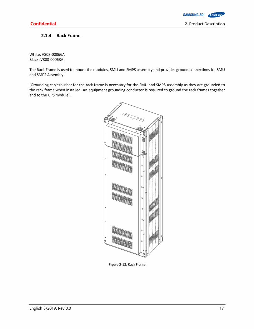
2.1.4 Rack Frame
White: V808-00066A Black: V808-00068A The Rack Frame is used to mount the modules, SMU and SMPS assembly and provides ground connections for SMU and SMPS Assembly. (Grounding cable/busbar for the rack frame is necessary for the SMU and SMPS Assembly as they are grounded to the rack frame when installed. An equipment grounding conductor is required to ground the rack frames together and to the UPS module).
Figure 2-13: Rack Frame
3. Installing the Product Confidential
18 English 8/2019. Rev 0.0
3. Installing the Product
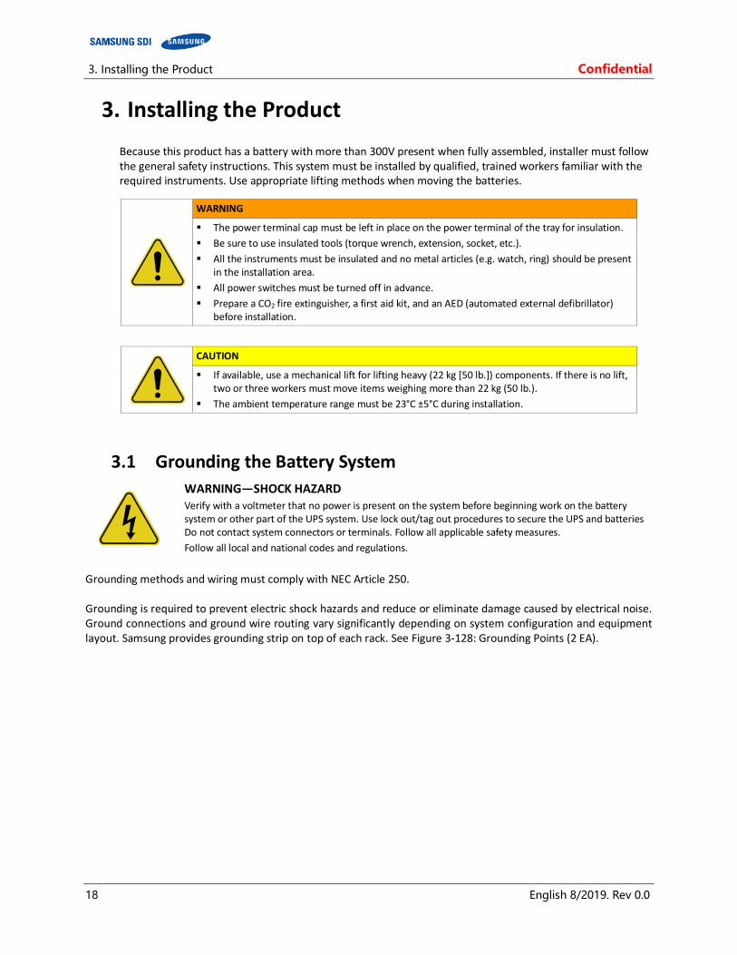
Because this product has a battery with more than 300V present when fully assembled, installer must follow the general safety instructions. This system must be installed by qualified, trained workers familiar with the required instruments. Use appropriate lifting methods when moving the batteries.
WARNING
The power terminal cap must be left in place on the power terminal of the tray for insulation.
Be sure to use insulated tools (torque wrench, extension, socket, etc.).
All the instruments must be insulated and no metal articles (e.g. watch, ring) should be present in the installation area.
All power switches must be turned off in advance.
Prepare a CO2 fire extinguisher, a first aid kit, and an AED (automated external defibrillator) before installation.
CAUTION
If available, use a mechanical lift for lifting heavy (22 kg [50 lb.]) components. If there is no lift, two or three workers must move items weighing more than 22 kg (50 lb.).
The ambient temperature range must be 23°C ±5°C during installation.
3.1 Grounding the Battery System
WARNING—SHOCK HAZARD Verify with a voltmeter that no power is present on the system before beginning work on the battery system or other part of the UPS system. Use lock out/tag out procedures to secure the UPS and batteries Do not contact system connectors or terminals. Follow all applicable safety measures.
Follow all local and national codes and regulations.
Grounding methods and wiring must comply with NEC Article 250. Grounding is required to prevent electric shock hazards and reduce or eliminate damage caused by electrical noise. Ground connections and ground wire routing vary significantly depending on system configuration and equipment layout. Samsung provides grounding strip on top of each rack. See Figure 3-128: Grounding Points (2 EA).
Confidential 3. Installing the Product
English 8/2019. Rev 0.0 19
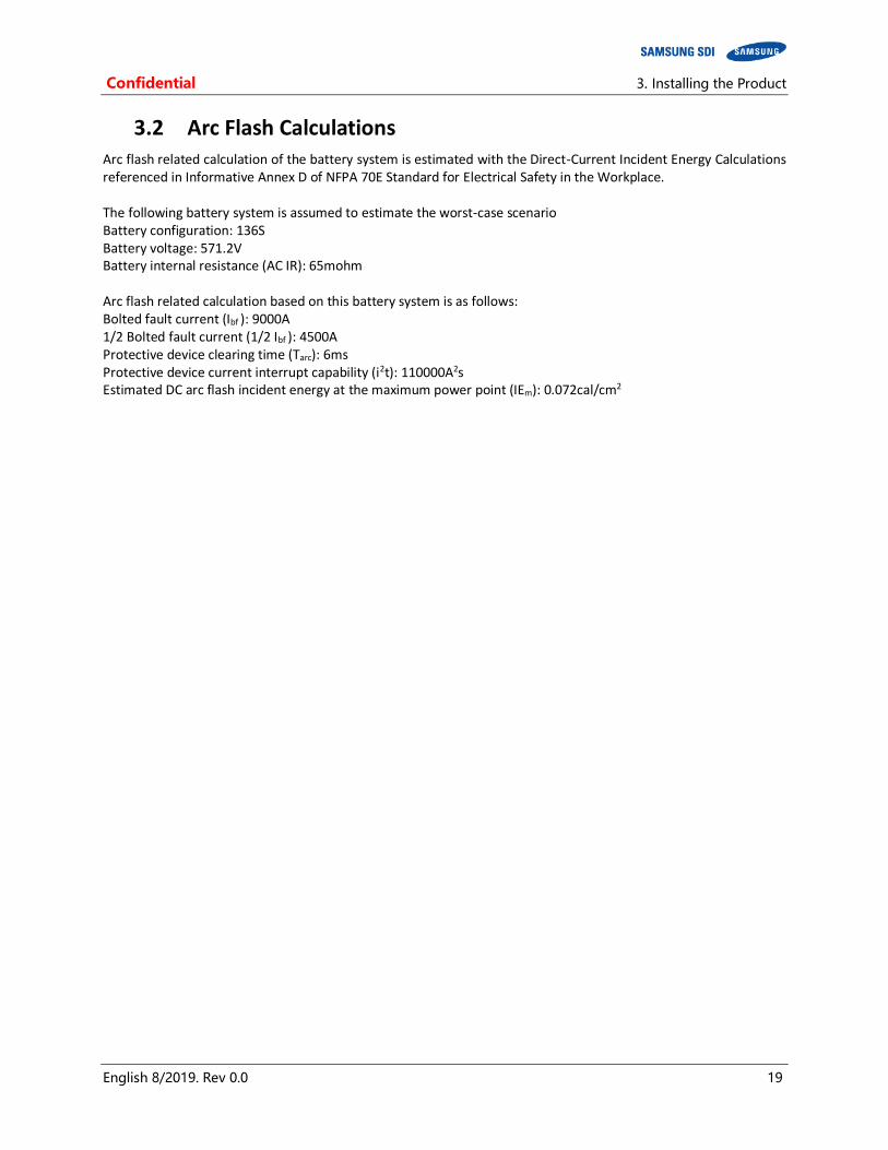
3.2 Arc Flash Calculations Arc flash related calculation of the battery system is estimated with the Direct-Current Incident Energy Calculations referenced in Informative Annex D of NFPA 70E Standard for Electrical Safety in the Workplace. The following battery system is assumed to estimate the worst-case scenario Battery configuration: 136S Battery voltage: 571.2V Battery internal resistance (AC IR): 65mohm Arc flash related calculation based on this battery system is as follows: Bolted fault current (Ibf
): 9000A 1/2 Bolted fault current (1/2 Ibf
): 4500A
Protective device clearing time (Tarc): 6ms Protective device current interrupt capability (i2t): 110000A2s Estimated DC arc flash incident energy at the maximum power point (IEm): 0.072cal/cm2
3. Installing the Product Confidential
20 English 8/2019. Rev 0.0
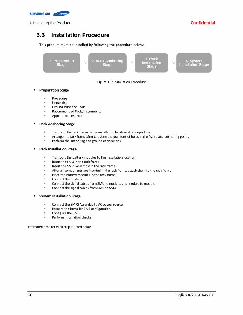
3.3 Installation Procedure
This product must be installed by following the procedure below:
Figure 3-1: Installation Procedure
Preparation Stage
Procedure Unpacking Ground Wire and Tools Recommended Tools/Instruments Appearance Inspection
Rack Anchoring Stage
Transport the rack frame to the installation location after unpacking Arrange the rack frame after checking the positions of holes in the frame and anchoring points Perform the anchoring and ground connections
Rack Installation Stage
Transport the battery modules to the installation location Insert the SMU in the rack frame Insert the SMPS Assembly in the rack frame After all components are inserted in the rack frame, attach them to the rack frame Place the battery modules in the rack frame Connect the busbars Connect the signal cables from SMU to module, and module to module Connect the signal cables from SMU to SMU
System Installation Stage
Connect the SMPS Assembly to AC power source Prepare the items for BMS configuration Configure the BMS Perform installation checks
Estimated time for each step is listed below.
1. Preparation Stage
2. Rack Anchoring Stage
3. Rack Installation
Stage
4. System Installation Stage
Confidential 3. Installing the Product
English 8/2019. Rev 0.0 21
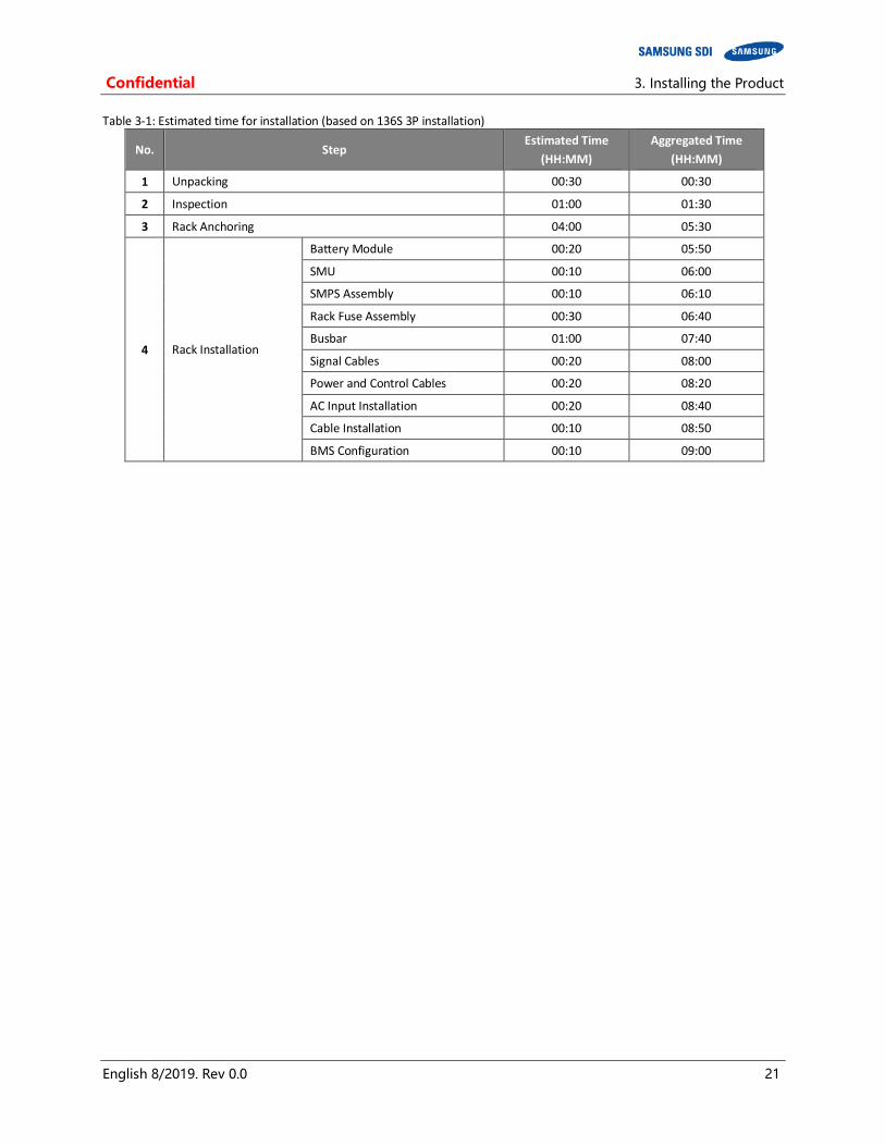
Table 3-1: Estimated time for installation (based on 136S 3P installation)
No. Step Estimated Time
(HH:MM)
Aggregated Time
(HH:MM)
1 Unpacking 00:30 00:30
2 Inspection 01:00 01:30
3 Rack Anchoring 04:00 05:30
4 Rack Installation
Battery Module 00:20 05:50
SMU 00:10 06:00
SMPS Assembly 00:10 06:10
Rack Fuse Assembly 00:30 06:40
Busbar 01:00 07:40
Signal Cables 00:20 08:00
Power and Control Cables 00:20 08:20
AC Input Installation 00:20 08:40
Cable Installation 00:10 08:50
BMS Configuration 00:10 09:00
3. Installing the Product Confidential
22 English 8/2019. Rev 0.0
3.4 Preparation Stage—Procedure
For the preparation stage, perform the following steps:
1. Create the installation plan and check the equipment and instruments for installation.
2. Check the arrival schedule of the parts required.
3. Unpack the equipment.
4. Inspect the equipment.
WARNING
Do not wear watches, rings, jewelry, or any other metal objects.
Wear electrically insulated gloves and safety shoes.
CAUTION
Store the product in a dust-free place with the moisture level of below 60% and the temperature level of 23°C ±5°C.
Keep components out of direct sunlight.
Confidential 3. Installing the Product
English 8/2019. Rev 0.0 23
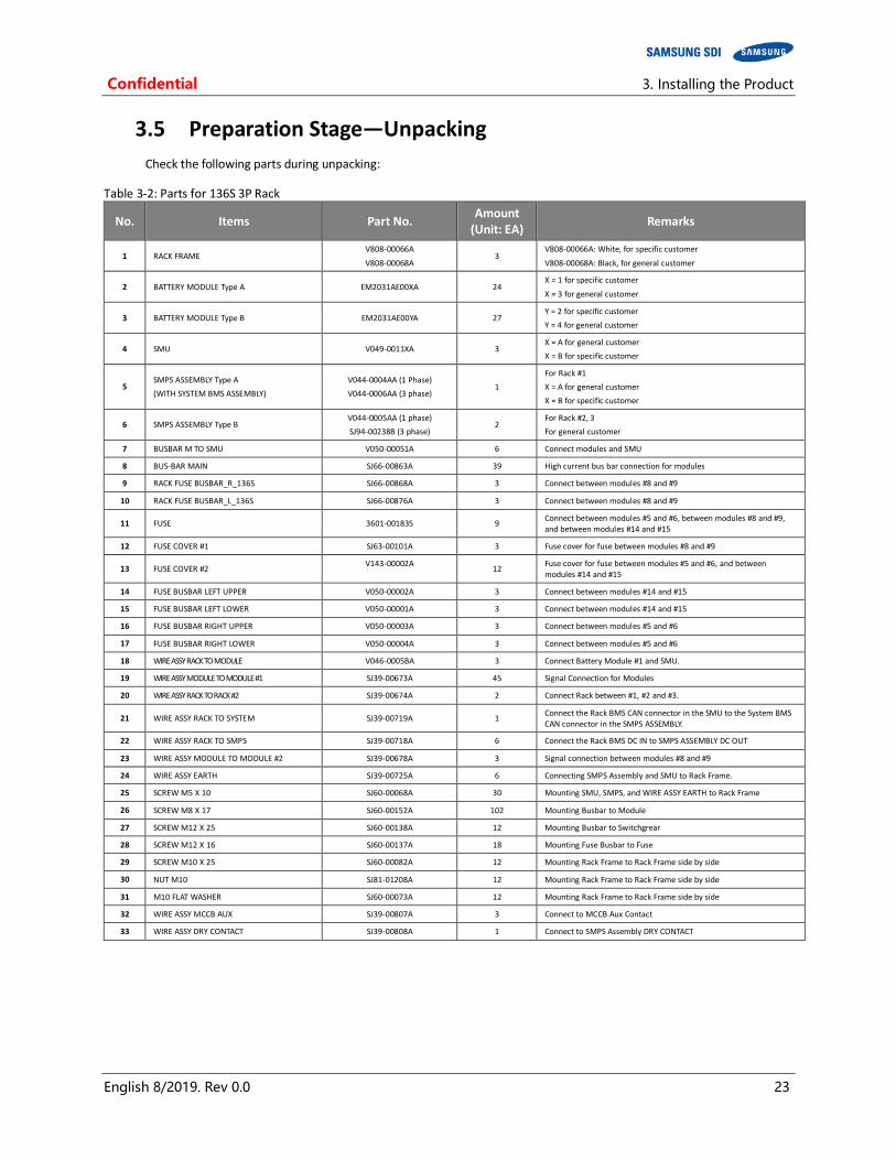
3.5 Preparation Stage—Unpacking
Check the following parts during unpacking:
Table 3-2: Parts for 136S 3P Rack
No. Items Part No. Amount
(Unit: EA) Remarks
1 RACK FRAME V808-00066A
V808-00068A 3
V808-00066A: White, for specific customer
V808-00068A: Black, for general customer
2 BATTERY MODULE Type A EM2031AE00XA 24 X = 1 for specific customer
X = 3 for general customer
3 BATTERY MODULE Type B EM2031AE00YA 27 Y = 2 for specific customer
Y = 4 for general customer
4 SMU V049-0011XA 3 X = A for general customer
X = B for specific customer
5 SMPS ASSEMBLY Type A
(WITH SYSTEM BMS ASSEMBLY)
V044-0004AA (1 Phase)
V044-0006AA (3 phase) 1
For Rack #1
X = A for general customer
X = B for specific customer
6 SMPS ASSEMBLY Type B V044-0005AA (1 phase)
SJ94-00238B (3 phase) 2
For Rack #2, 3
For general customer
7 BUSBAR M TO SMU V050-00051A 6 Connect modules and SMU
8 BUS-BAR MAIN SJ66-00863A 39 High current bus bar connection for modules
9 RACK FUSE BUSBAR_R_136S SJ66-00868A 3 Connect between modules #8 and #9
10 RACK FUSE BUSBAR_L_136S SJ66-00876A 3 Connect between modules #8 and #9
11 FUSE 3601-001835 9 Connect between modules #5 and #6, between modules #8 and #9, and between modules #14 and #15
12 FUSE COVER #1 SJ63-00101A 3 Fuse cover for fuse between modules #8 and #9
13 FUSE COVER #2 V143-00002A
12 Fuse cover for fuse between modules #5 and #6, and between modules #14 and #15
14 FUSE BUSBAR LEFT UPPER V050-00002A 3 Connect between modules #14 and #15
15 FUSE BUSBAR LEFT LOWER V050-00001A 3 Connect between modules #14 and #15
16 FUSE BUSBAR RIGHT UPPER V050-00003A 3 Connect between modules #5 and #6
17 FUSE BUSBAR RIGHT LOWER V050-00004A 3 Connect between modules #5 and #6
18 WIRE ASSY RACK TO MODULE V046-0005BA 3 Connect Battery Module #1 and SMU.
19 WIRE ASSY MODULE TO MODULE #1 SJ39-00673A 45 Signal Connection for Modules
20 WIRE ASSY RACK TO RACK #2 SJ39-00674A 2 Connect Rack between #1, #2 and #3.
21 WIRE ASSY RACK TO SYSTEM SJ39-00719A 1 Connect the Rack BMS CAN connector in the SMU to the System BMS CAN connector in the SMPS ASSEMBLY.
22 WIRE ASSY RACK TO SMPS SJ39-00718A 6 Connect the Rack BMS DC IN to SMPS ASSEMBLY DC OUT
23 WIRE ASSY MODULE TO MODULE #2 SJ39-00678A 3 Signal connection between modules #8 and #9
24 WIRE ASSY EARTH SJ39-00725A 6 Connecting SMPS Assembly and SMU to Rack Frame.
25 SCREW M5 X 10 SJ60-00068A 30 Mounting SMU, SMPS, and WIRE ASSY EARTH to Rack Frame
26 SCREW M8 X 17 SJ60-00152A 102 Mounting Busbar to Module
27 SCREW M12 X 25 SJ60-00138A 12 Mounting Busbar to Switchgrear
28 SCREW M12 X 16 SJ60-00137A 18 Mounting Fuse Busbar to Fuse
29 SCREW M10 X 25 SJ60-00082A 12 Mounting Rack Frame to Rack Frame side by side
30 NUT M10 SJ81-01208A 12 Mounting Rack Frame to Rack Frame side by side
31 M10 FLAT WASHER SJ60-00073A 12 Mounting Rack Frame to Rack Frame side by side
32 WIRE ASSY MCCB AUX SJ39-00807A 3 Connect to MCCB Aux Contact
33 WIRE ASSY DRY CONTACT SJ39-00808A 1 Connect to SMPS Assembly DRY CONTACT
3. Installing the Product Confidential
24 English 8/2019. Rev 0.0
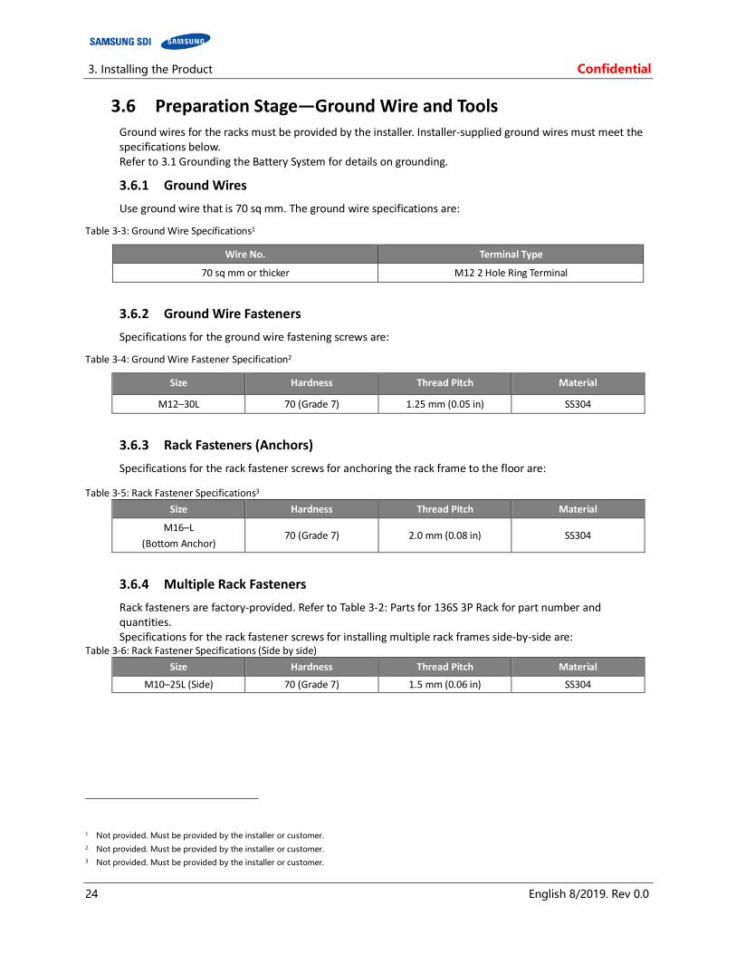
3.6 Preparation Stage—Ground Wire and Tools Ground wires for the racks must be provided by the installer. Installer-supplied ground wires must meet the specifications below. Refer to 3.1 Grounding the Battery System for details on grounding.
3.6.1 Ground Wires
Use ground wire that is 70 sq mm. The ground wire specifications are:
Table 3-3: Ground Wire Specifications1
Wire No. Terminal Type
70 sq mm or thicker M12 2 Hole Ring Terminal
3.6.2 Ground Wire Fasteners
Specifications for the ground wire fastening screws are:
Table 3-4: Ground Wire Fastener Specification2
Size Hardness Thread Pitch Material
M12–30L 70 (Grade 7) 1.25 mm (0.05 in) SS304
3.6.3 Rack Fasteners (Anchors)
Specifications for the rack fastener screws for anchoring the rack frame to the floor are:
Table 3-5: Rack Fastener Specifications3
Size Hardness Thread Pitch Material
M16–L
(Bottom Anchor) 70 (Grade 7) 2.0 mm (0.08 in) SS304
3.6.4 Multiple Rack Fasteners
Rack fasteners are factory-provided. Refer to Table 3-2: Parts for 136S 3P Rack for part number and quantities. Specifications for the rack fastener screws for installing multiple rack frames side-by-side are:
Table 3-6: Rack Fastener Specifications (Side by side)
Size Hardness Thread Pitch Material
M10–25L (Side) 70 (Grade 7) 1.5 mm (0.06 in) SS304
1 Not provided. Must be provided by the installer or customer.
2 Not provided. Must be provided by the installer or customer.
3 Not provided. Must be provided by the installer or customer.
Confidential 3. Installing the Product
English 8/2019. Rev 0.0 25
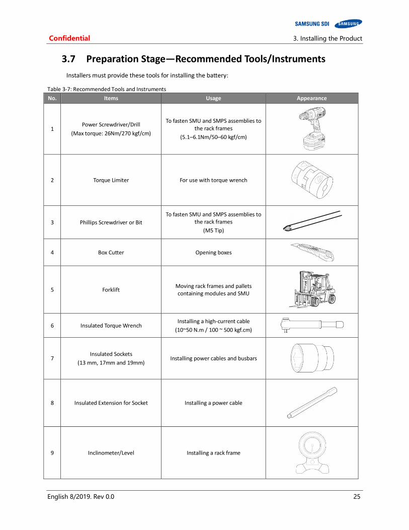
3.7 Preparation Stage—Recommended Tools/Instruments
Installers must provide these tools for installing the battery:
Table 3-7: Recommended Tools and Instruments
No. Items Usage Appearance
1 Power Screwdriver/Drill
(Max torque: 26Nm/270 kgf/cm)
To fasten SMU and SMPS assemblies to the rack frames
(5.1–6.1Nm/50–60 kgf/cm)
2 Torque Limiter For use with torque wrench
3 Phillips Screwdriver or Bit
To fasten SMU and SMPS assemblies to the rack frames
(M5 Tip)
4 Box Cutter Opening boxes
5 Forklift Moving rack frames and pallets containing modules and SMU
6 Insulated Torque Wrench Installing a high-current cable
(10~50 N.m / 100 ~ 500 kgf.cm)
7 Insulated Sockets
(13 mm, 17mm and 19mm) Installing power cables and busbars
8 Insulated Extension for Socket Installing a power cable
9 Inclinometer/Level Installing a rack frame

3. Installing the Product Confidential
26 English 8/2019. Rev 0.0
No. Items Usage Appearance
10 Battery Tester Measure battery module’s voltage and
internal impedance
Confidential 3. Installing the Product
English 8/2019. Rev 0.0 27
3.8 Preparation Stage—Visual Inspection
CAUTION
If any defects are found during the inspection, contact the SAMSUNG SDI customer service department.
3.8.1 Inspection of the Rack Frame
After transporting the rack frame to the installation location, check for:
Structural damage Paint peeling Damaged or protruding screws.
After completion, install or package the rack for protection during storage.
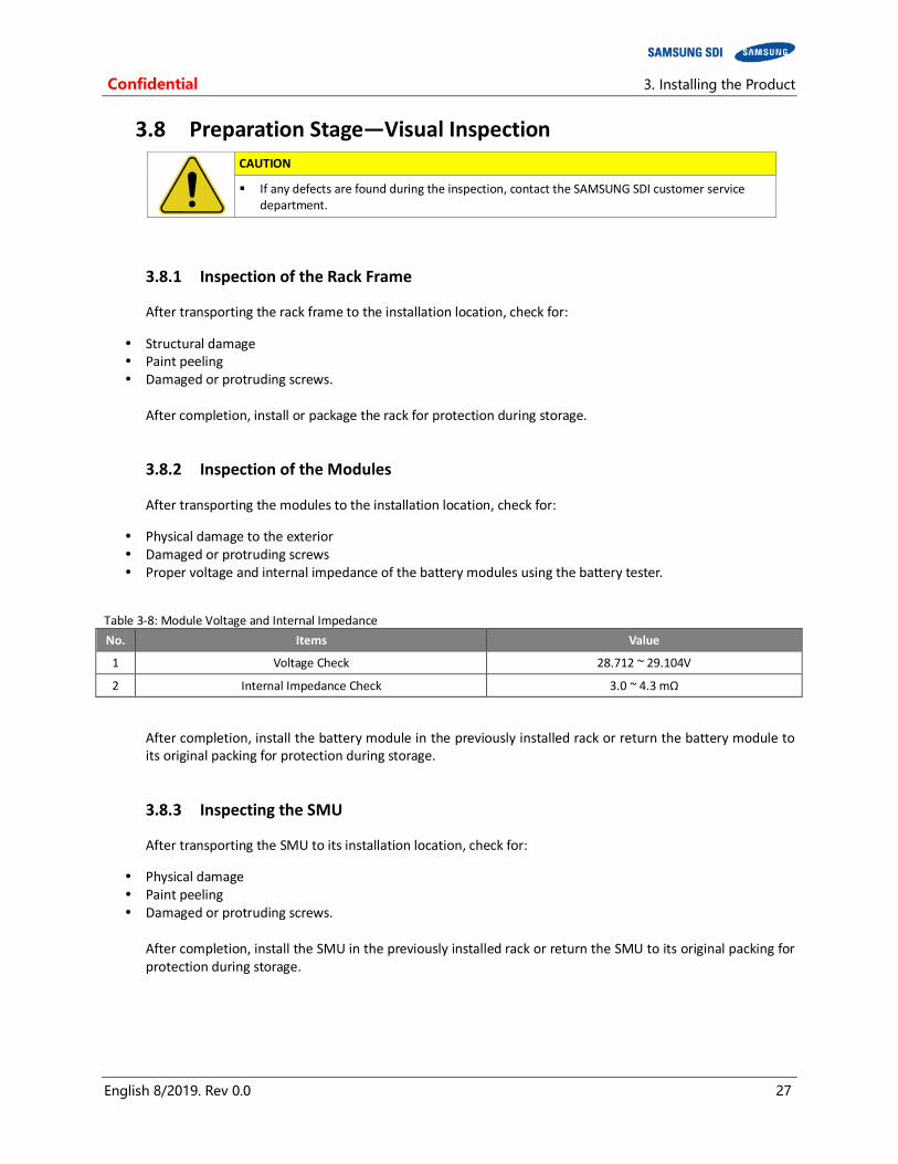
3.8.2 Inspection of the Modules
After transporting the modules to the installation location, check for:
Physical damage to the exterior Damaged or protruding screws Proper voltage and internal impedance of the battery modules using the battery tester.
Table 3-8: Module Voltage and Internal Impedance
No. Items Value
1 Voltage Check 28.712 ~ 29.104V
2 Internal Impedance Check 3.0 ~ 4.3 mΩ
After completion, install the battery module in the previously installed rack or return the battery module to its original packing for protection during storage.
3.8.3 Inspecting the SMU
After transporting the SMU to its installation location, check for:
Physical damage Paint peeling Damaged or protruding screws.
After completion, install the SMU in the previously installed rack or return the SMU to its original packing for protection during storage.

3. Installing the Product Confidential
28 English 8/2019. Rev 0.0
3.8.4 Inspecting the SMPS assembly
After transporting the SMPS Assembly to its installation location, check for:
Physical damage Paint peeling Damaged or protruding screws.
After completion, install the SMPS in the previously installed rack or return the SMPS to its original packing for protection during storage.
Confidential 3. Installing the Product
English 8/2019. Rev 0.0 29
3.9 Rack Anchoring Stage
Install the rack frame on a flat, level surface.
To attach the rack and perform the related works
CAUTION
Use a proper transportation method considering the weight of the rack frame.
Ensure that the safety of the working place is maintained.
When using a forklift, lift the rack frame from the front.
When a forklift cannot be used, use a mechanical lift or move it by hand with three or more people.
Use lock washers to prevent bolts from loosening.
Use an inclinometer or carpenter’s level to ensure that the rack frame is plumb.
NOTICE
Failure to anchor the rack frame on a flat and level surface may distort the rack frame after installing the racks side-by-side.
Frame distortion may make the rack doors difficult or impossible to open.
NOTICE
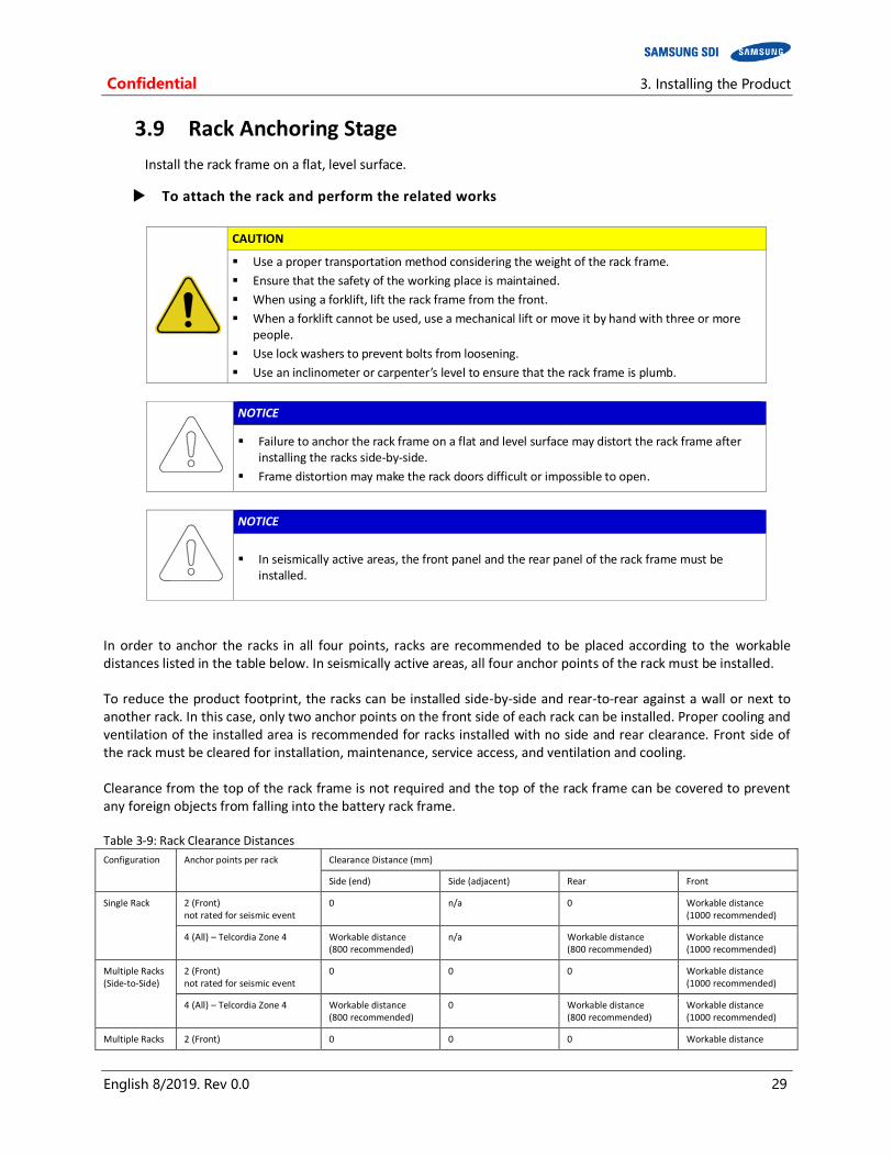
In seismically active areas, the front panel and the rear panel of the rack frame must be installed.
In order to anchor the racks in all four points, racks are recommended to be placed according to the workable distances listed in the table below. In seismically active areas, all four anchor points of the rack must be installed. To reduce the product footprint, the racks can be installed side-by-side and rear-to-rear against a wall or next to another rack. In this case, only two anchor points on the front side of each rack can be installed. Proper cooling and ventilation of the installed area is recommended for racks installed with no side and rear clearance. Front side of the rack must be cleared for installation, maintenance, service access, and ventilation and cooling. Clearance from the top of the rack frame is not required and the top of the rack frame can be covered to prevent any foreign objects from falling into the battery rack frame. Table 3-9: Rack Clearance Distances
Configuration Anchor points per rack Clearance Distance (mm)
Side (end) Side (adjacent) Rear Front
Single Rack 2 (Front) not rated for seismic event
0 n/a 0 Workable distance (1000 recommended)
4 (All) – Telcordia Zone 4 Workable distance (800 recommended)
n/a Workable distance (800 recommended)
Workable distance (1000 recommended)
Multiple Racks (Side-to-Side)
2 (Front) not rated for seismic event
0 0 0 Workable distance (1000 recommended)
4 (All) – Telcordia Zone 4 Workable distance (800 recommended)
0 Workable distance (800 recommended)
Workable distance (1000 recommended)
Multiple Racks 2 (Front) 0 0 0 Workable distance
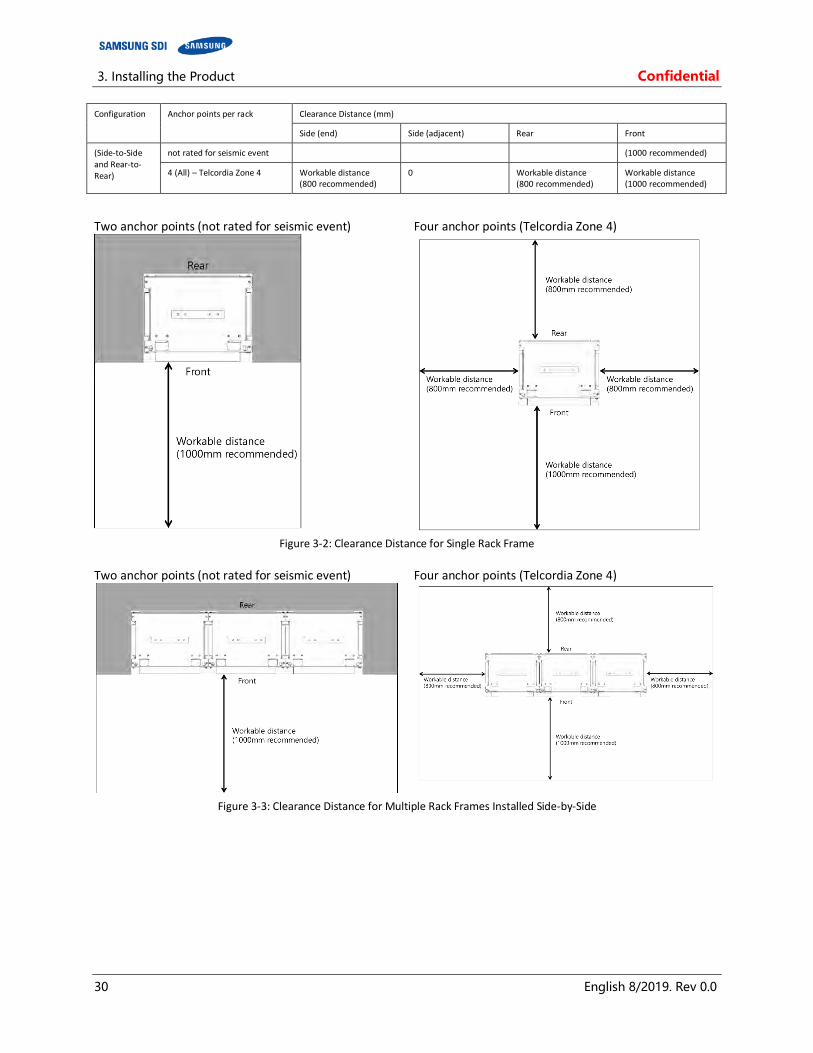
3. Installing the Product Confidential
30 English 8/2019. Rev 0.0
Configuration Anchor points per rack Clearance Distance (mm)
Side (end) Side (adjacent) Rear Front
(Side-to-Side and Rear-to-Rear)
not rated for seismic event (1000 recommended)
4 (All) – Telcordia Zone 4 Workable distance (800 recommended)
0 Workable distance (800 recommended)
Workable distance (1000 recommended)
Two anchor points (not rated for seismic event) Four anchor points (Telcordia Zone 4)
Figure 3-2: Clearance Distance for Single Rack Frame
Two anchor points (not rated for seismic event) Four anchor points (Telcordia Zone 4)
Figure 3-3: Clearance Distance for Multiple Rack Frames Installed Side-by-Side
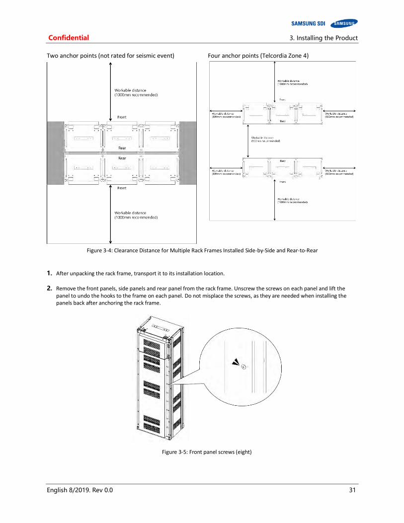
Confidential 3. Installing the Product
English 8/2019. Rev 0.0 31
Two anchor points (not rated for seismic event) Four anchor points (Telcordia Zone 4)
Figure 3-4: Clearance Distance for Multiple Rack Frames Installed Side-by-Side and Rear-to-Rear
1. After unpacking the rack frame, transport it to its installation location.
2. Remove the front panels, side panels and rear panel from the rack frame. Unscrew the screws on each panel and lift the panel to undo the hooks to the frame on each panel. Do not misplace the screws, as they are needed when installing the panels back after anchoring the rack frame.
Figure 3-5: Front panel screws (eight)

3. Installing the Product Confidential
32 English 8/2019. Rev 0.0
Figure 3-6: Front panel hooks (four)
Figure 3-7: Side panel screws (six)

Confidential 3. Installing the Product
English 8/2019. Rev 0.0 33
Figure 3-8: Side panel hooks (four)
Figure 3-9: Rear panel screws (eight)
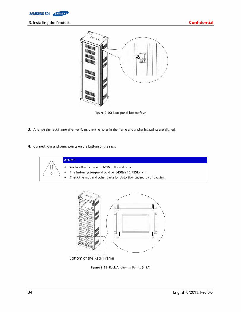
3. Installing the Product Confidential
34 English 8/2019. Rev 0.0
Figure 3-10: Rear panel hooks (four)
3. Arrange the rack frame after verifying that the holes in the frame and anchoring points are aligned.
4. Connect four anchoring points on the bottom of the rack.
NOTICE
Anchor the frame with M16 bolts and nuts.
The fastening torque should be 140Nm / 1,425kgf cm.
Check the rack and other parts for distortion caused by unpacking.
Figure 3-11: Rack Anchoring Points (4 EA)
Bottom of the Rack Frame
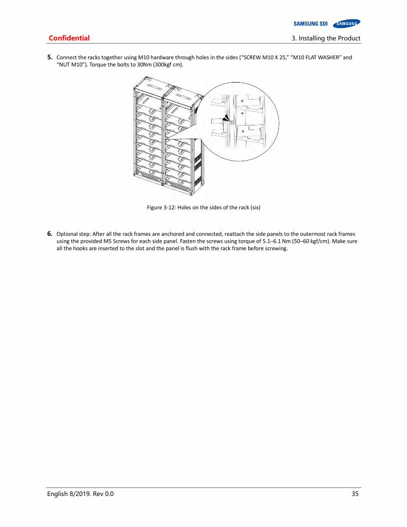
Confidential 3. Installing the Product
English 8/2019. Rev 0.0 35
5. Connect the racks together using M10 hardware through holes in the sides (“SCREW M10 X 25,” “M10 FLAT WASHER” and “NUT M10”). Torque the bolts to 30Nm (300kgf cm).
Figure 3-12: Holes on the sides of the rack (six)
6. Optional step: After all the rack frames are anchored and connected, reattach the side panels to the outermost rack frames using the provided M5 Screws for each side panel. Fasten the screws using torque of 5.1–6.1 Nm (50–60 kgf/cm). Make sure all the hooks are inserted to the slot and the panel is flush with the rack frame before screwing.

3. Installing the Product Confidential
36 English 8/2019. Rev 0.0
Figure 3-13: Reattaching the Side Panels (four hooks and six screws for each panel)
7. Reattach the rear panels to the rack frames using the provided M5 Screws for each rear panel. Fasten the screws using torque of 5.1–6.1 Nm (50–60 kgf/cm). Make sure all the hooks are inserted to the slot and the panel is flush with the rack frame before screwing.
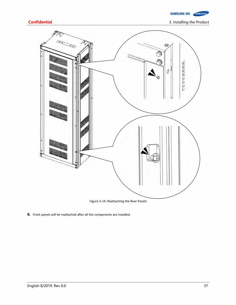
Confidential 3. Installing the Product
English 8/2019. Rev 0.0 37
Figure 3-14: Reattaching the Rear Panels
8. Front panels will be reattached after all the components are installed.

3. Installing the Product Confidential
38 English 8/2019. Rev 0.0
3.10 Rack Installation Stage
WARNING
Arc Flash and Shock Hazard
Insulated tools are required for any work on this energized equipment.
WARNING
Sharp Edges
Wear gloves and other protective gear to prevent injury.
WARNING
Pinch Point Use caution when working in the enclosure to prevent injury.
CAUTION
Heavy Object
Can cause muscle strain or back injury.
Use lifting aids and proper lifting techniques when moving trays, batteries and other heavy objects.

Confidential 3. Installing the Product
English 8/2019. Rev 0.0 39
3.10.1 Front Door Removal
1. Open the front door of the panel using the provided key.
Figure 3-15: Front door ajar
2. Remove the earth cable from the rack frame to the front door. Do not misplace the two screws and the earth cable.
Figure 3-16: Removing the earth cable
3. Lift the front door to remove it from its hinge. Do not misplace the door.
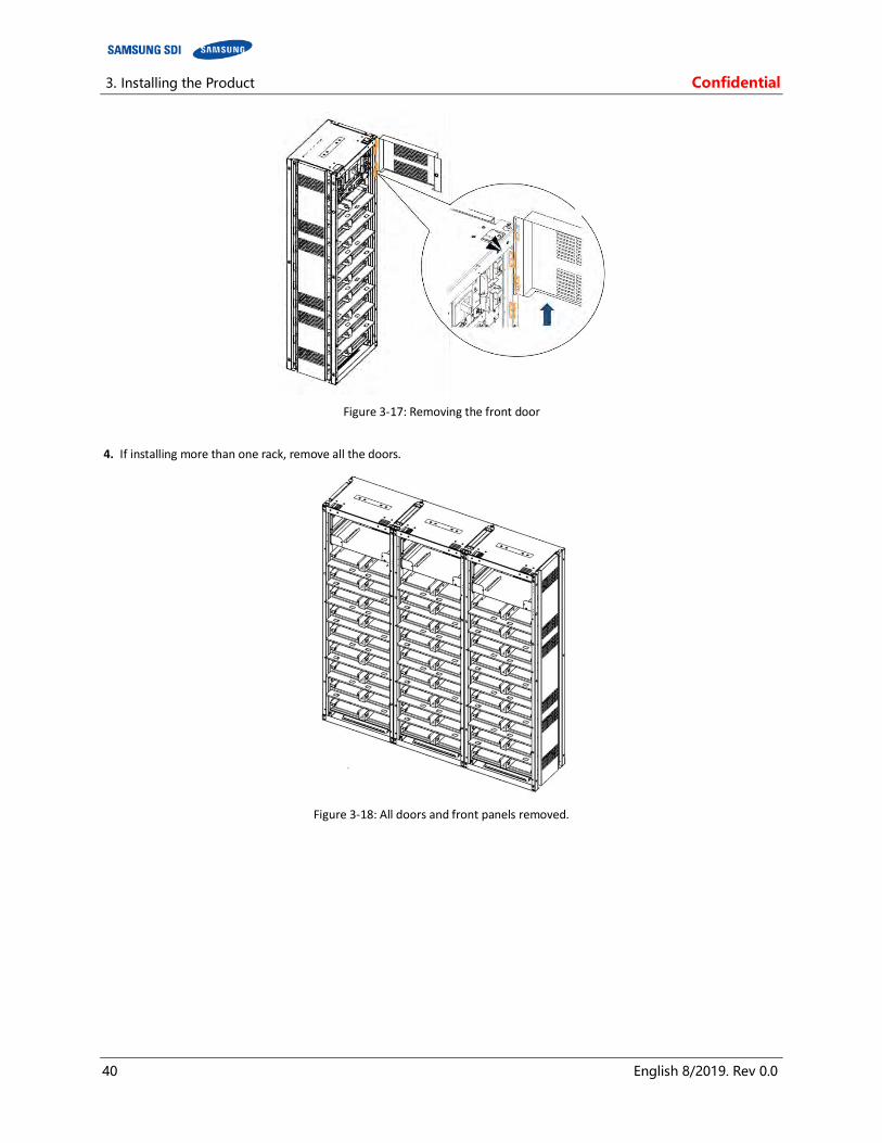
3. Installing the Product Confidential
40 English 8/2019. Rev 0.0
Figure 3-17: Removing the front door
4. If installing more than one rack, remove all the doors.
Figure 3-18: All doors and front panels removed.

Confidential 3. Installing the Product
English 8/2019. Rev 0.0 41
3.10.2 SMU and SMPS Assembly Installation
Important
Attach each SMU to its rack frame with four M5 x 10L screws. (Torque: 5.1–6.1 Nm [50–60 kgf cm])
Verify that the torque setting is correct.
1. Insert the SMU through the front of the rack as shown in Figure 3-19: Inserting SMU
Figure 3-19: Inserting SMU
2. After all SMU’s are inserted in the rack frames, attach each to the rack frame with four M5 x 10L bolts. (Torque: 5.1–6.1 Nm [50–60 kgf cm])
Figure 3-20: Attaching a SMU to a Rack Frame
3. After all SMU’s are inserted into the rack frame, connect the ground cable.

3. Installing the Product Confidential
42 English 8/2019. Rev 0.0
NOTICE
Connect a ground cable between the SMU and the Rack Frame (SCREW M5 x 10L). (Torque: 5.1–6.1 Nm [50–60 kgf∙cm])
Verify that the torque setting is correct.
Figure 3-21: Ground Cable Connection to the SMU
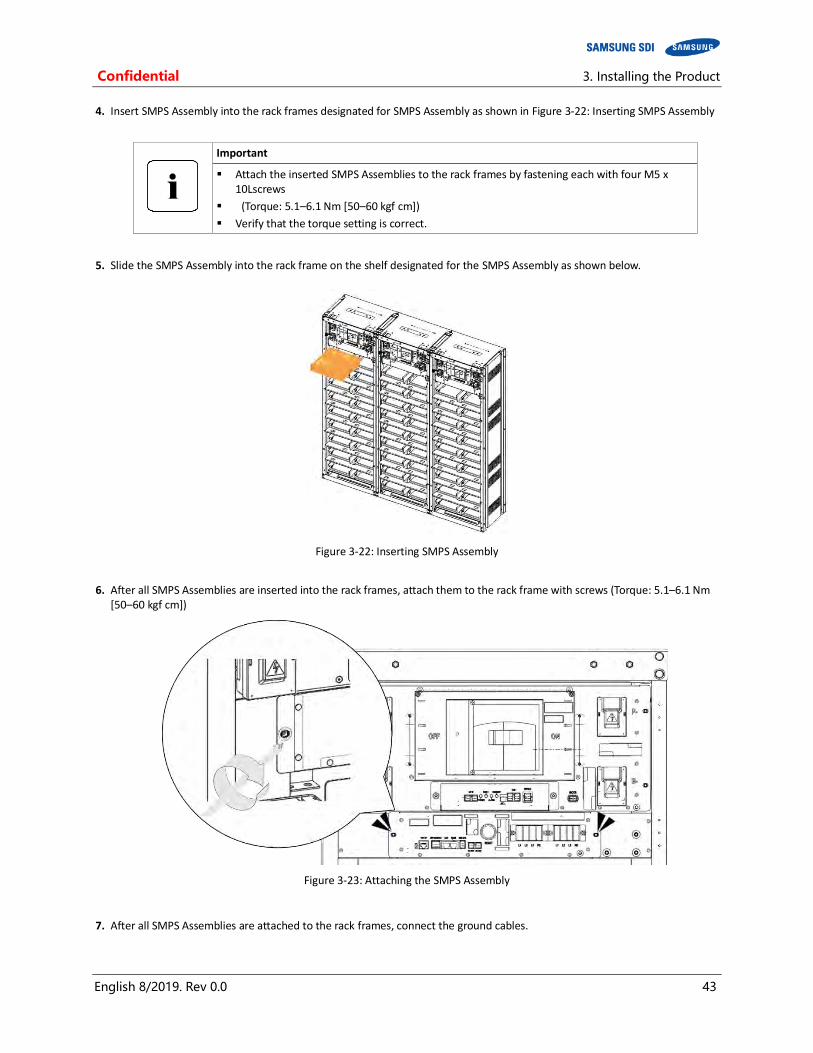
Confidential 3. Installing the Product
English 8/2019. Rev 0.0 43
4. Insert SMPS Assembly into the rack frames designated for SMPS Assembly as shown in Figure 3-22: Inserting SMPS Assembly
Important
Attach the inserted SMPS Assemblies to the rack frames by fastening each with four M5 x 10Lscrews
(Torque: 5.1–6.1 Nm [50–60 kgf cm])
Verify that the torque setting is correct.
5. Slide the SMPS Assembly into the rack frame on the shelf designated for the SMPS Assembly as shown below.
Figure 3-22: Inserting SMPS Assembly
6. After all SMPS Assemblies are inserted into the rack frames, attach them to the rack frame with screws (Torque: 5.1–6.1 Nm [50–60 kgf cm])
Figure 3-23: Attaching the SMPS Assembly
7. After all SMPS Assemblies are attached to the rack frames, connect the ground cables.

3. Installing the Product Confidential
44 English 8/2019. Rev 0.0
NOTICE
Connect a ground cable between the SMPS Assembly and the Rack Frame with an M5 x 10L screw. (Torque: 5.1–6.1 Nm [50–60 kgf cm])
Verify that the torque setting is correct.
Figure 3-24: Ground Cable Connection to the SMPS Assembly
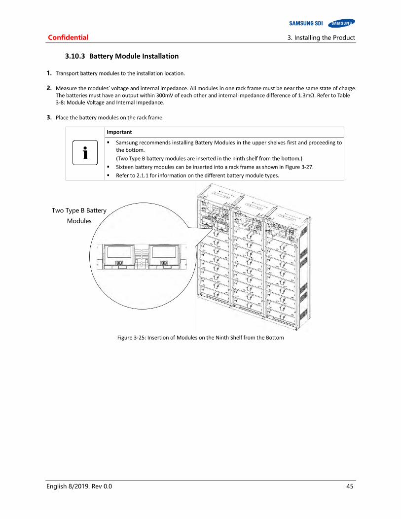
Confidential 3. Installing the Product
English 8/2019. Rev 0.0 45
3.10.3 Battery Module Installation
1. Transport battery modules to the installation location.
2. Measure the modules’ voltage and internal impedance. All modules in one rack frame must be near the same state of charge. The batteries must have an output within 300mV of each other and internal impedance difference of 1.3mΩ. Refer to Table 3-8: Module Voltage and Internal Impedance.
3. Place the battery modules on the rack frame.
Important
Samsung recommends installing Battery Modules in the upper shelves first and proceeding to the bottom.
(Two Type B battery modules are inserted in the ninth shelf from the bottom.)
Sixteen battery modules can be inserted into a rack frame as shown in Figure 3-27.
Refer to 2.1.1 for information on the different battery module types.
Figure 3-25: Insertion of Modules on the Ninth Shelf from the Bottom
Two Type B Battery
Modules
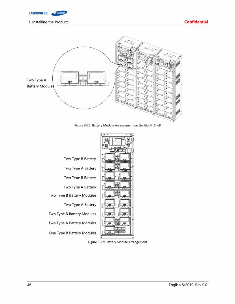
3. Installing the Product Confidential
46 English 8/2019. Rev 0.0
Figure 3-26: Battery Module Arrangement on the Eighth Shelf
Figure 3-27: Battery Module Arrangement
Two Type A
Battery Modules
Two Type B Battery
Modules Two Type A Battery
Modules Two Type B Battery
Modules Two Type A Battery
Modules Two Type B Battery Modules
Two Type A Battery
Modules Two Type B Battery Modules
Two Type A Battery Modules
One Type B Battery Modules
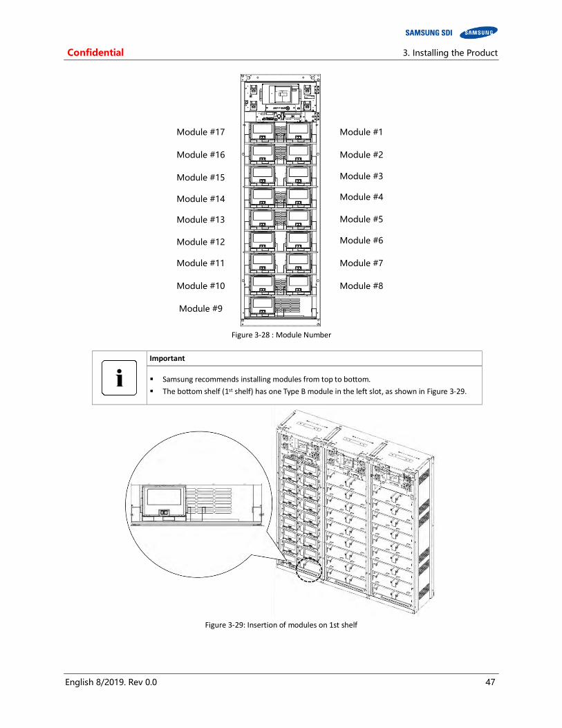
Confidential 3. Installing the Product
English 8/2019. Rev 0.0 47
Figure 3-28 : Module Number
Important
Samsung recommends installing modules from top to bottom.
The bottom shelf (1st shelf) has one Type B module in the left slot, as shown in Figure 3-29.
Figure 3-29: Insertion of modules on 1st shelf
Module #8
Module #7
Module #6
Module #5
Module #4
Module #3
Module #2
Module #1
Module #9
Module #10
Module #11
Module #12
Module #13
Module #14
Module #15
Module #16
Module #17

3. Installing the Product Confidential
48 English 8/2019. Rev 0.0
3.10.4 Fuse-Busbar Assembly
Three types of fuse-busbar assemblies must be assembled before installing them to the Battery Modules.
NOTICE
Rack Fuse Busbar Assembly is assembled at the installation location. M12 X 16L screws are used to assemble the busbars and fuse. The fastening torque should be 30 Nm (300 kgf/cm). When assembling the fuse, make sure the “red indicator arm” on the fuse is facing the front of the unit.
1. Assemble the Rack fuse Bus-bar assembly. Rack fuse bus-bar assembly is comprised of one “RACKFUSE BUSBAR_R_136S”, one “RACKFUSE BUSBAR_L_136S”, two “SCREW M12 X 16”, one “FUSE COVER #1”, and one “FUSE”
Figure 3-30: Rack Fuse Busbar Assembly
Figure 3-31: Rack Fuse Busbar Assembly (Fuse Cover)
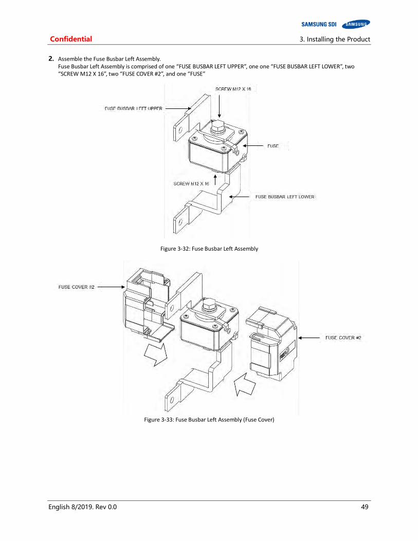
Confidential 3. Installing the Product
English 8/2019. Rev 0.0 49
2. Assemble the Fuse Busbar Left Assembly. Fuse Busbar Left Assembly is comprised of one “FUSE BUSBAR LEFT UPPER”, one one “FUSE BUSBAR LEFT LOWER”, two “SCREW M12 X 16”, two “FUSE COVER #2”, and one “FUSE”
Figure 3-32: Fuse Busbar Left Assembly
Figure 3-33: Fuse Busbar Left Assembly (Fuse Cover)

3. Installing the Product Confidential
50 English 8/2019. Rev 0.0
3. Assemble the Fuse Busbar Right Assembly. Fuse Busbar Right Assembly is comprised of one “FUSE BUSBAR RIGHT UPPER”, one one “FUSE BUSBAR RIGHT LOWER”, two “SCREW M12 X 16”, two “FUSE COVER #2”, and one “FUSE”
Figure 3-34: Fuse Busbar Right Assembly
Figure 3-35: Fuse Busbar Right Assembly (Fuse Cover)
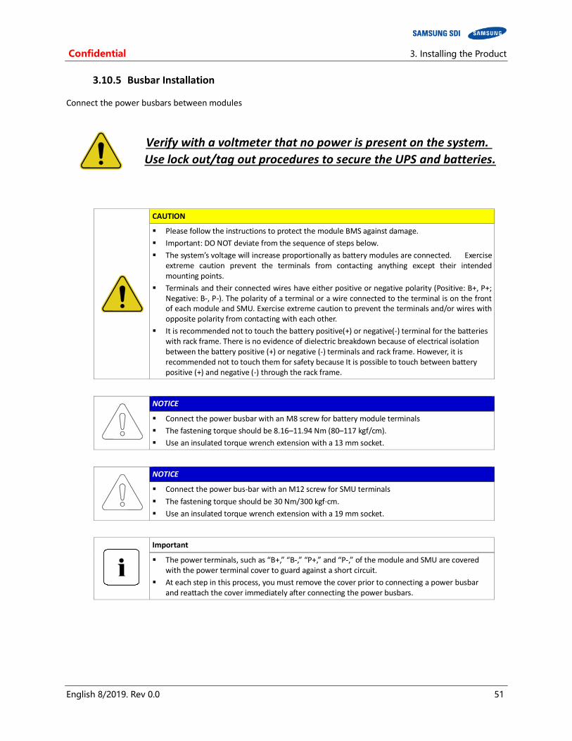
Confidential 3. Installing the Product
English 8/2019. Rev 0.0 51
3.10.5 Busbar Installation
Connect the power busbars between modules
Verify with a voltmeter that no power is present on the system.
Use lock out/tag out procedures to secure the UPS and batteries.
CAUTION
Please follow the instructions to protect the module BMS against damage.
Important: DO NOT deviate from the sequence of steps below.
The system’s voltage will increase proportionally as battery modules are connected. Exercise extreme caution prevent the terminals from contacting anything except their intended mounting points.
Terminals and their connected wires have either positive or negative polarity (Positive: B+, P+; Negative: B-, P-). The polarity of a terminal or a wire connected to the terminal is on the front of each module and SMU. Exercise extreme caution to prevent the terminals and/or wires with opposite polarity from contacting with each other.
It is recommended not to touch the battery positive(+) or negative(-) terminal for the batteries with rack frame. There is no evidence of dielectric breakdown because of electrical isolation between the battery positive (+) or negative (-) terminals and rack frame. However, it is recommended not to touch them for safety because It is possible to touch between battery positive (+) and negative (-) through the rack frame.
NOTICE
Connect the power busbar with an M8 screw for battery module terminals
The fastening torque should be 8.16–11.94 Nm (80–117 kgf/cm).
Use an insulated torque wrench extension with a 13 mm socket.
NOTICE
Connect the power bus-bar with an M12 screw for SMU terminals
The fastening torque should be 30 Nm/300 kgf∙cm.
Use an insulated torque wrench extension with a 19 mm socket.
Important
The power terminals, such as “B+,” “B-,” “P+,” and “P-,” of the module and SMU are covered with the power terminal cover to guard against a short circuit.
At each step in this process, you must remove the cover prior to connecting a power busbar and reattach the cover immediately after connecting the power busbars.

3. Installing the Product Confidential
52 English 8/2019. Rev 0.0
1. Remove Battery Module #1’s front cover and the SMU B- terminal cover.
Figure 3-36: Removing the Module #1’s Cover and SMU B- Terminal Cover
2. Connect SMU B- and Module #1 B- using “BUSBAR M TO SMU.” SMU B- terminal is connected using an M12 screw and Battery Module #1 B- terminal is connected using an M8 screw.
Figure 3-37: Connect SMU B- and Module #1 B-

Confidential 3. Installing the Product
English 8/2019. Rev 0.0 53
3. Reattach SMU’s B- terminal cover.
Figure 3-38: Restore SMU’s B- Terminal
4. Remove Battery Module #2’s front cover.
Figure 3-39: Remove Battery Module #2’s Front Cover
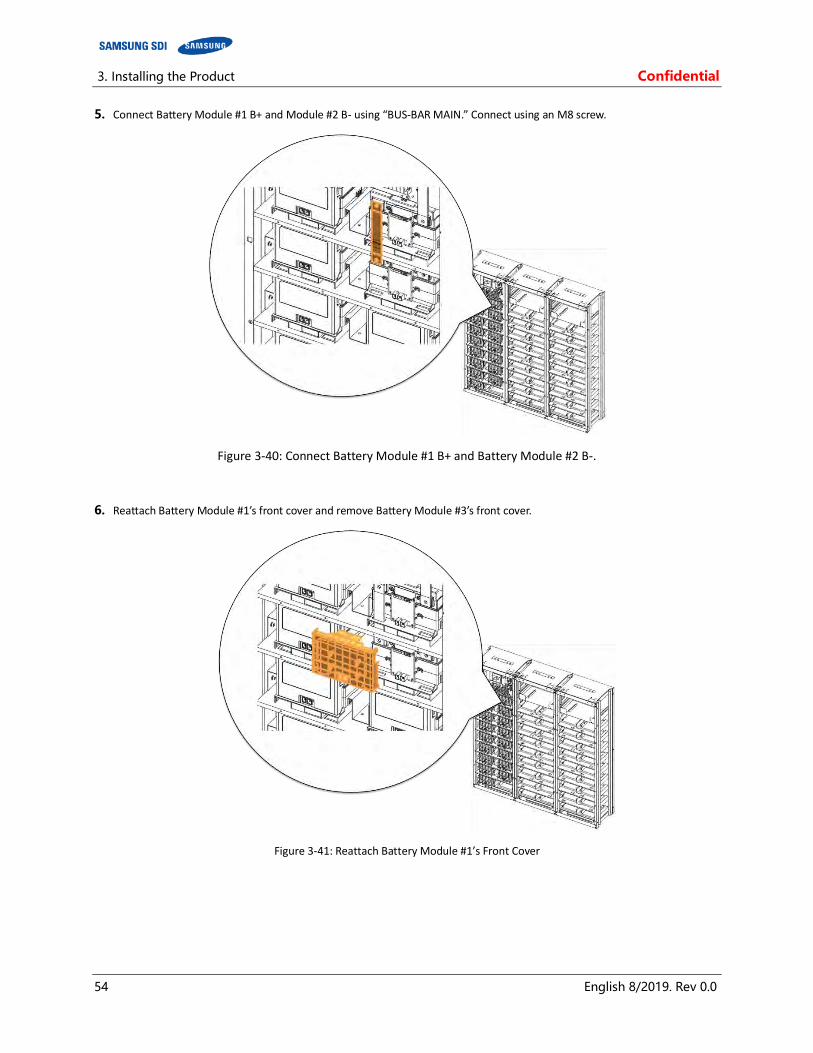
3. Installing the Product Confidential
54 English 8/2019. Rev 0.0
5. Connect Battery Module #1 B+ and Module #2 B- using “BUS-BAR MAIN.” Connect using an M8 screw.
Figure 3-40: Connect Battery Module #1 B+ and Battery Module #2 B-.
6. Reattach Battery Module #1’s front cover and remove Battery Module #3’s front cover.
Figure 3-41: Reattach Battery Module #1’s Front Cover

Confidential 3. Installing the Product
English 8/2019. Rev 0.0 55
Figure 3-42: Remove Battery Module #2’s Front Cover
7. Connect Battery Module #2 B+ and Battery Module #3 B- using “BUS-BAR MAIN.” Connect using an M8 screw.
Figure 3-43: Connect Battery Module #2 B+ and Battery Module #3 B-.

3. Installing the Product Confidential
56 English 8/2019. Rev 0.0
8. Reattach Battery Module #2’s front cover and remove Battery Module #4’s front cover.
Figure 3-44: Reattach Battery Module #2’s Front Cover
Figure 3-45: Remove Battery Module #4’s Front Cover
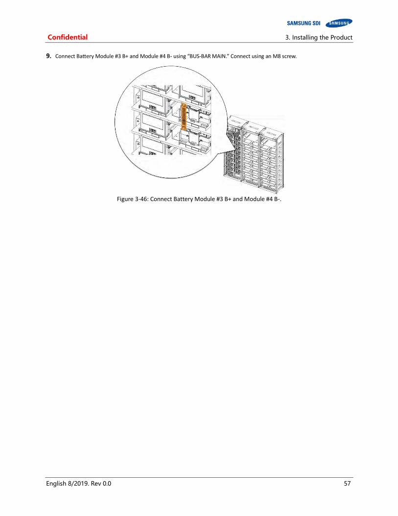
Confidential 3. Installing the Product
English 8/2019. Rev 0.0 57
9. Connect Battery Module #3 B+ and Module #4 B- using “BUS-BAR MAIN.” Connect using an M8 screw.
Figure 3-46: Connect Battery Module #3 B+ and Module #4 B-.

3. Installing the Product Confidential
58 English 8/2019. Rev 0.0
10. Reattach Battery Module #3’s front cover and remove Battery Module #5’s front cover.
Figure 3-47: Reattach Battery Module #3’s Front Cover
Figure 3-48: Remove Battery Module #5’s Front Cover
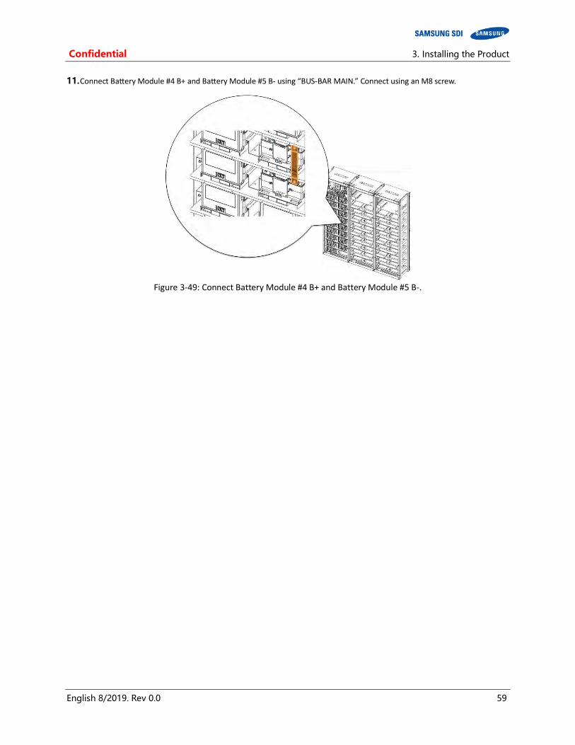
Confidential 3. Installing the Product
English 8/2019. Rev 0.0 59
11. Connect Battery Module #4 B+ and Battery Module #5 B- using “BUS-BAR MAIN.” Connect using an M8 screw.
Figure 3-49: Connect Battery Module #4 B+ and Battery Module #5 B-.
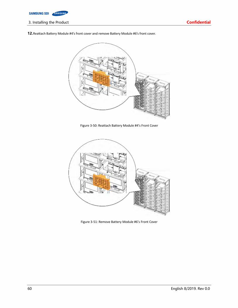
3. Installing the Product Confidential
60 English 8/2019. Rev 0.0
12. Reattach Battery Module #4’s front cover and remove Battery Module #6’s front cover.
Figure 3-50: Reattach Battery Module #4’s Front Cover
Figure 3-51: Remove Battery Module #6’s Front Cover
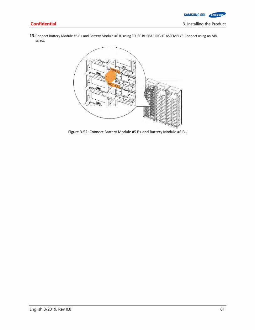
Confidential 3. Installing the Product
English 8/2019. Rev 0.0 61
13. Connect Battery Module #5 B+ and Battery Module #6 B- using “FUSE BUSBAR RIGHT ASSEMBLY”. Connect using an M8 screw.
Figure 3-52: Connect Battery Module #5 B+ and Battery Module #6 B-.
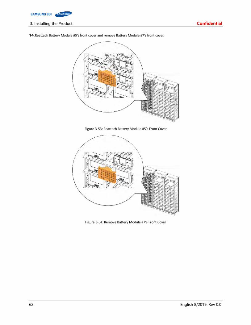
3. Installing the Product Confidential
62 English 8/2019. Rev 0.0
14. Reattach Battery Module #5’s front cover and remove Battery Module #7’s front cover.
Figure 3-53: Reattach Battery Module #5’s Front Cover
Figure 3-54: Remove Battery Module #7’s Front Cover
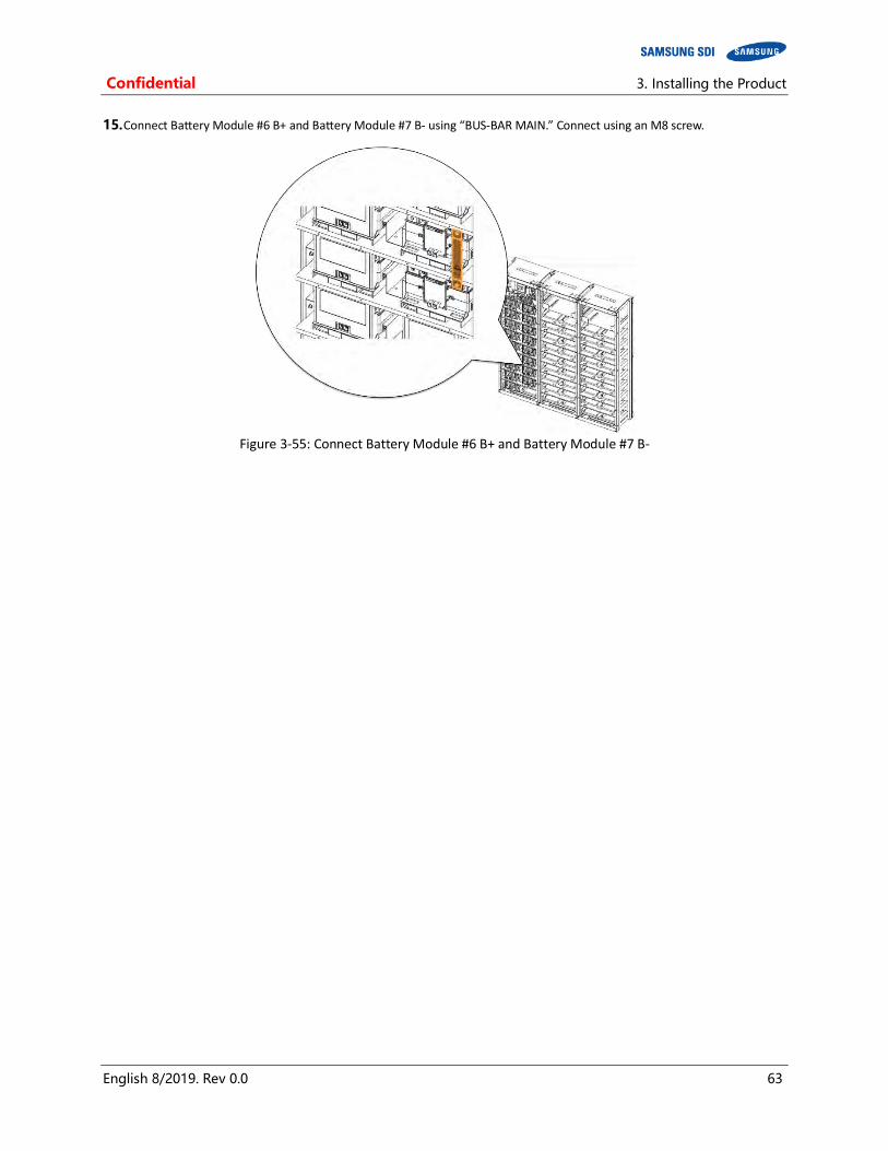
Confidential 3. Installing the Product
English 8/2019. Rev 0.0 63
15. Connect Battery Module #6 B+ and Battery Module #7 B- using “BUS-BAR MAIN.” Connect using an M8 screw.
Figure 3-55: Connect Battery Module #6 B+ and Battery Module #7 B-

3. Installing the Product Confidential
64 English 8/2019. Rev 0.0
16. Reattach Battery Module #6’s front cover and remove Battery Module #8’s front cover.
Figure 3-56: Reattach Battery Module #6’s Front Cover
Figure 3-57: Remove Battery Module #8’s Front Cover
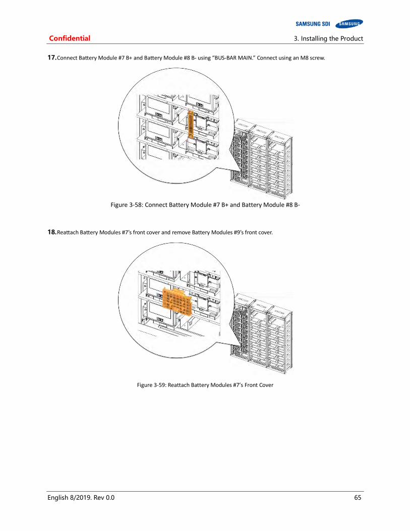
Confidential 3. Installing the Product
English 8/2019. Rev 0.0 65
17. Connect Battery Module #7 B+ and Battery Module #8 B- using “BUS-BAR MAIN.” Connect using an M8 screw.
Figure 3-58: Connect Battery Module #7 B+ and Battery Module #8 B-
18. Reattach Battery Modules #7’s front cover and remove Battery Modules #9’s front cover.
Figure 3-59: Reattach Battery Modules #7’s Front Cover

3. Installing the Product Confidential
66 English 8/2019. Rev 0.0
Figure 3-60: Remove Battery Modules #9’s Front Cover

Confidential 3. Installing the Product
English 8/2019. Rev 0.0 67
19. Connect Battery Module #8 B+ and Battery Module #9 B- using “RACK FUSE BUSBAR ASSEMBLY” Connect using an M8 screw.
Figure 3-61: Connect Battery Module #8 B+ and Battery Module #9 B-.
20. Reattach Battery Module #8’s front cover and remove Battery Module #10’s front cover.
Figure 3-62: Reattach Battery Modules #8’s Front Cover

3. Installing the Product Confidential
68 English 8/2019. Rev 0.0
Figure 3-63: Remove Battery Modules #10’s Front Cover
21. Connect Battery Module #9 B+ and Battery Module #10 B- using “BUS-BAR MAIN” Connect using an M8 screw.
Figure 3-64 Connect Battery Module #9 B+ and Battery Module #10 B-.
22. Reattach Battery Module #9’s front cover and remove Battery Module #11’s front cover.

Confidential 3. Installing the Product
English 8/2019. Rev 0.0 69
Figure 3-65: Reattach Battery Module #9’s Front Cover
Figure 3-66: Remove Battery Module #11’s Front Cover
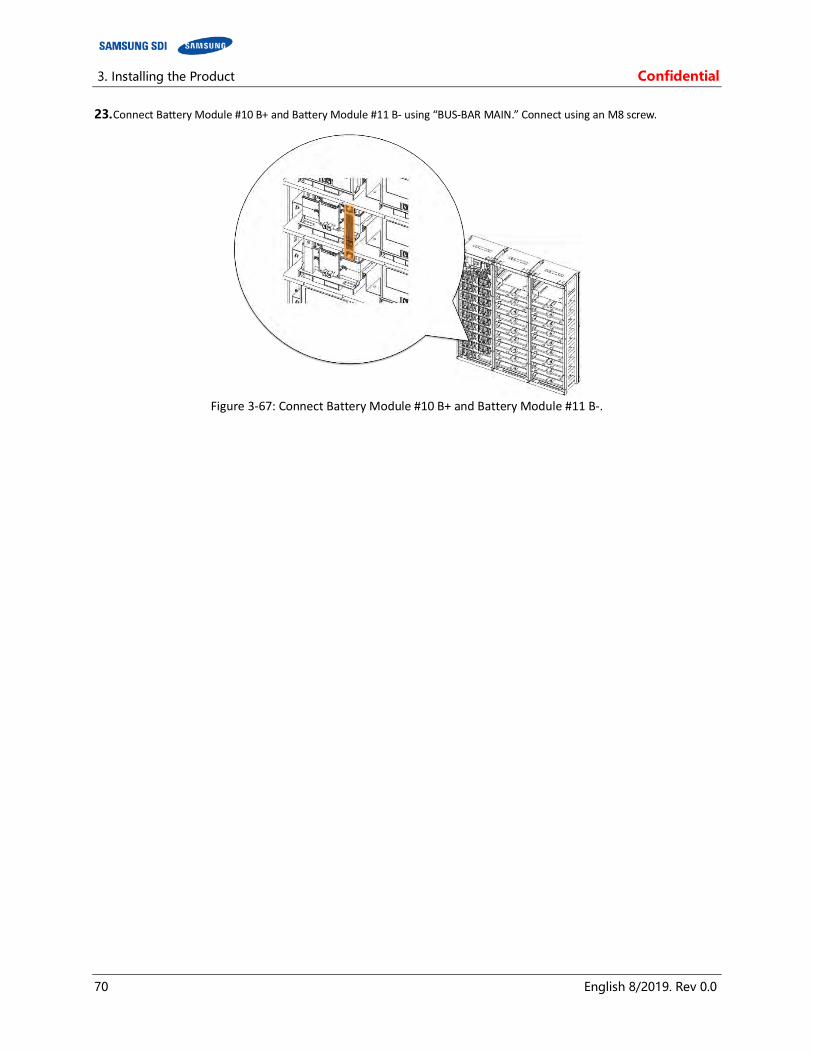
3. Installing the Product Confidential
70 English 8/2019. Rev 0.0
23. Connect Battery Module #10 B+ and Battery Module #11 B- using “BUS-BAR MAIN.” Connect using an M8 screw.
Figure 3-67: Connect Battery Module #10 B+ and Battery Module #11 B-.
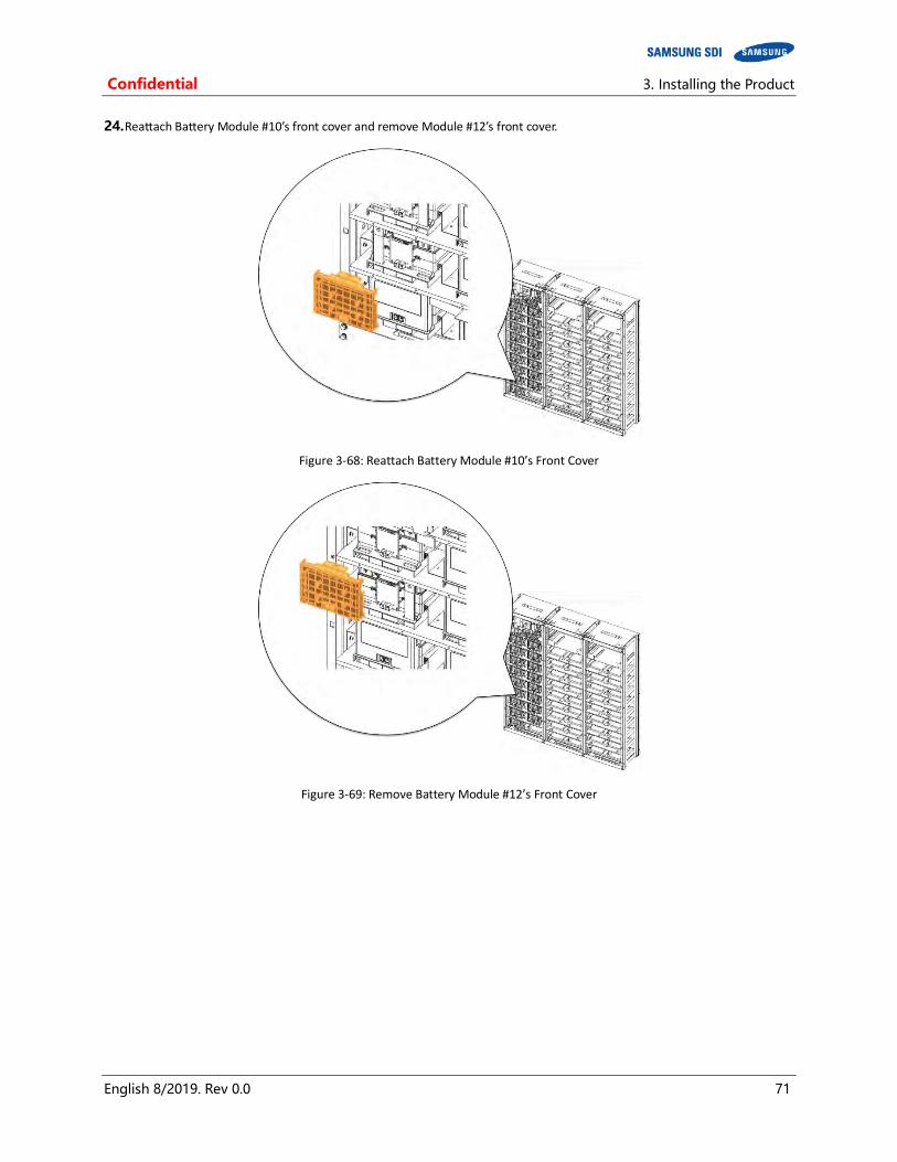
Confidential 3. Installing the Product
English 8/2019. Rev 0.0 71
24. Reattach Battery Module #10’s front cover and remove Module #12’s front cover.
Figure 3-68: Reattach Battery Module #10’s Front Cover
Figure 3-69: Remove Battery Module #12’s Front Cover
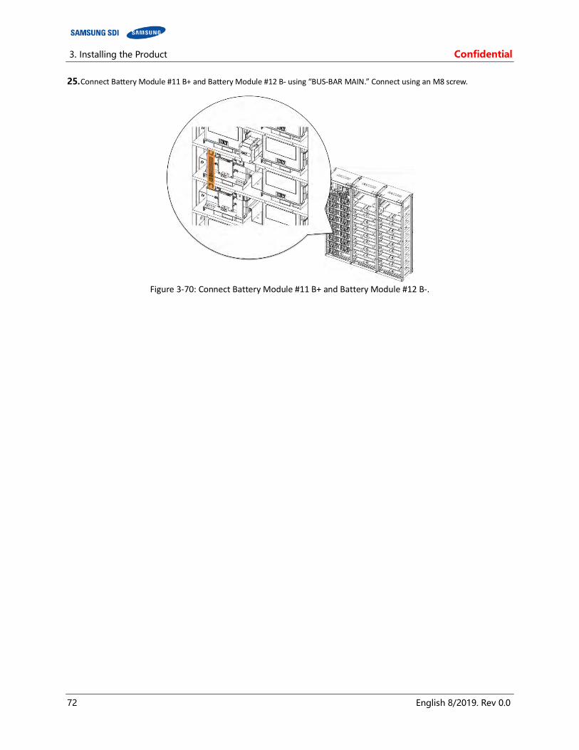
3. Installing the Product Confidential
72 English 8/2019. Rev 0.0
25. Connect Battery Module #11 B+ and Battery Module #12 B- using “BUS-BAR MAIN.” Connect using an M8 screw.
Figure 3-70: Connect Battery Module #11 B+ and Battery Module #12 B-.
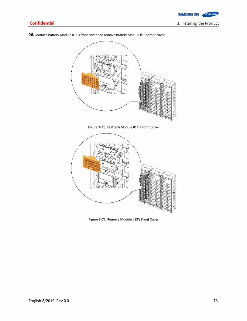
Confidential 3. Installing the Product
English 8/2019. Rev 0.0 73
26. Reattach Battery Module #11’s front cover and remove Battery Module #13’s front cover.
Figure 3-71: Reattach Module #11’s Front Cover
Figure 3-72: Remove Module #13’s Front Cover
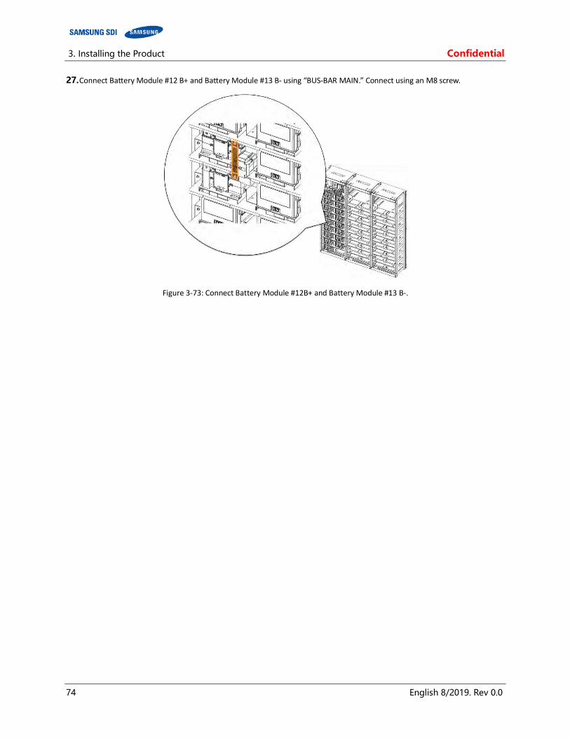
3. Installing the Product Confidential
74 English 8/2019. Rev 0.0
27. Connect Battery Module #12 B+ and Battery Module #13 B- using “BUS-BAR MAIN.” Connect using an M8 screw.
Figure 3-73: Connect Battery Module #12B+ and Battery Module #13 B-.
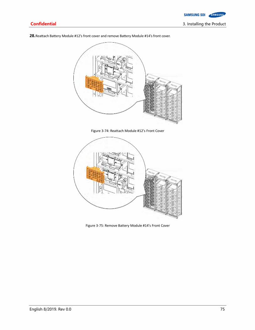
Confidential 3. Installing the Product
English 8/2019. Rev 0.0 75
28. Reattach Battery Module #12’s front cover and remove Battery Module #14’s front cover.
Figure 3-74: Reattach Module #12’s Front Cover
Figure 3-75: Remove Battery Module #14’s Front Cover
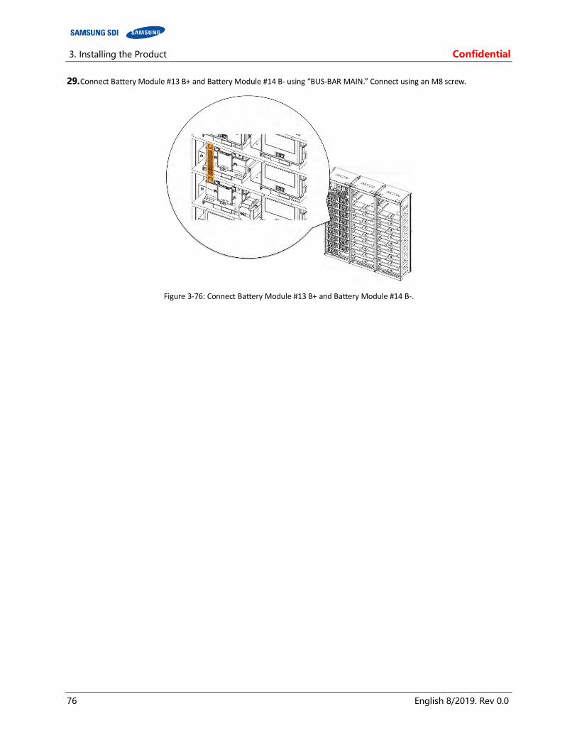
3. Installing the Product Confidential
76 English 8/2019. Rev 0.0
29. Connect Battery Module #13 B+ and Battery Module #14 B- using “BUS-BAR MAIN.” Connect using an M8 screw.
Figure 3-76: Connect Battery Module #13 B+ and Battery Module #14 B-.
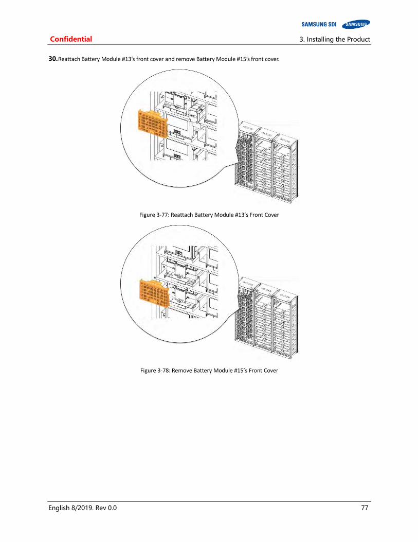
Confidential 3. Installing the Product
English 8/2019. Rev 0.0 77
30. Reattach Battery Module #13’s front cover and remove Battery Module #15’s front cover.
Figure 3-77: Reattach Battery Module #13’s Front Cover
Figure 3-78: Remove Battery Module #15’s Front Cover
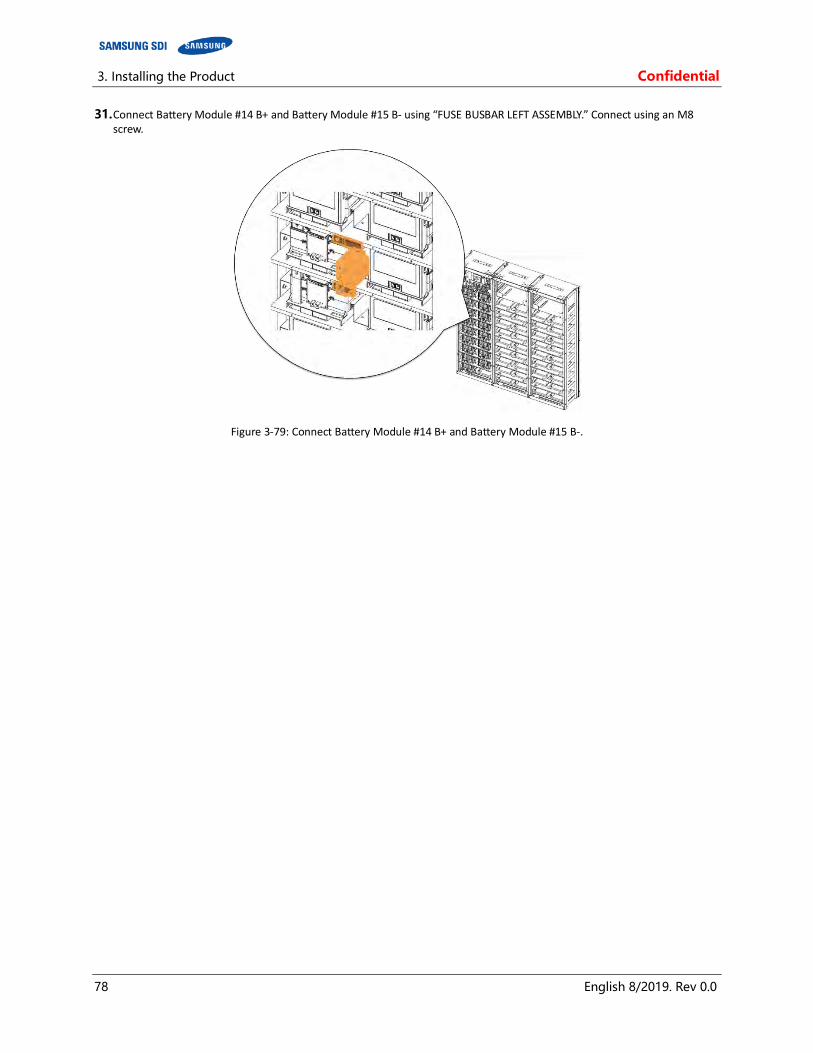
3. Installing the Product Confidential
78 English 8/2019. Rev 0.0
31. Connect Battery Module #14 B+ and Battery Module #15 B- using “FUSE BUSBAR LEFT ASSEMBLY.” Connect using an M8 screw.
Figure 3-79: Connect Battery Module #14 B+ and Battery Module #15 B-.

Confidential 3. Installing the Product
English 8/2019. Rev 0.0 79
32. Reattach Battery Module #14’s front cover and remove Battery Module #16’s front cover.
Figure 3-80: Reattach Battery Module #14’s Front Cover
Figure 3-81: Remove Battery Module #16’s Front Cover

3. Installing the Product Confidential
80 English 8/2019. Rev 0.0
33. Connect Battery Module #15 B+ and Battery Module #16 B- using “BUS-BAR MAIN.” Connect using an M8 screw.
Figure 3-82: Connect Battery Module #15 B+ and Battery Module #16 B-.

Confidential 3. Installing the Product
English 8/2019. Rev 0.0 81
34. Reattach Battery Module #15’s front cover and remove Battery Module #17’s front cover.
Figure 3-83: Reattach Battery Module #15’s Front Cover
Figure 3-84: Remove Battery Module #17’s Front Cover

3. Installing the Product Confidential
82 English 8/2019. Rev 0.0
35. Connect Battery Module #16 B+ and Battery Module #17 B- using “BUS-BAR MAIN”. Connect using M8 screw.
Figure 3-85: Connect Battery Module #16 B+ and Battery Module #17 B-.

Confidential 3. Installing the Product
English 8/2019. Rev 0.0 83
36. Reattach Battery Module #16’s front cover and remove SMU’s B+ terminal cover.
Figure 3-86: Reattach Battery Module #15’s Front Cover
Figure 3-87: Remove SMU B+ Terminal Cover
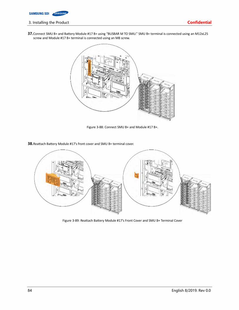
3. Installing the Product Confidential
84 English 8/2019. Rev 0.0
37. Connect SMU B+ and Battery Module #17 B+ using “BUSBAR M TO SMU.” SMU B+ terminal is connected using an M12xL25 screw and Module #17 B+ terminal is connected using an M8 screw.
Figure 3-88: Connect SMU B+ and Module #17 B+.
38. Reattach Battery Module #17’s front cover and SMU B+ terminal cover.
Figure 3-89: Reattach Battery Module #17’s Front Cover and SMU B+ Terminal Cover
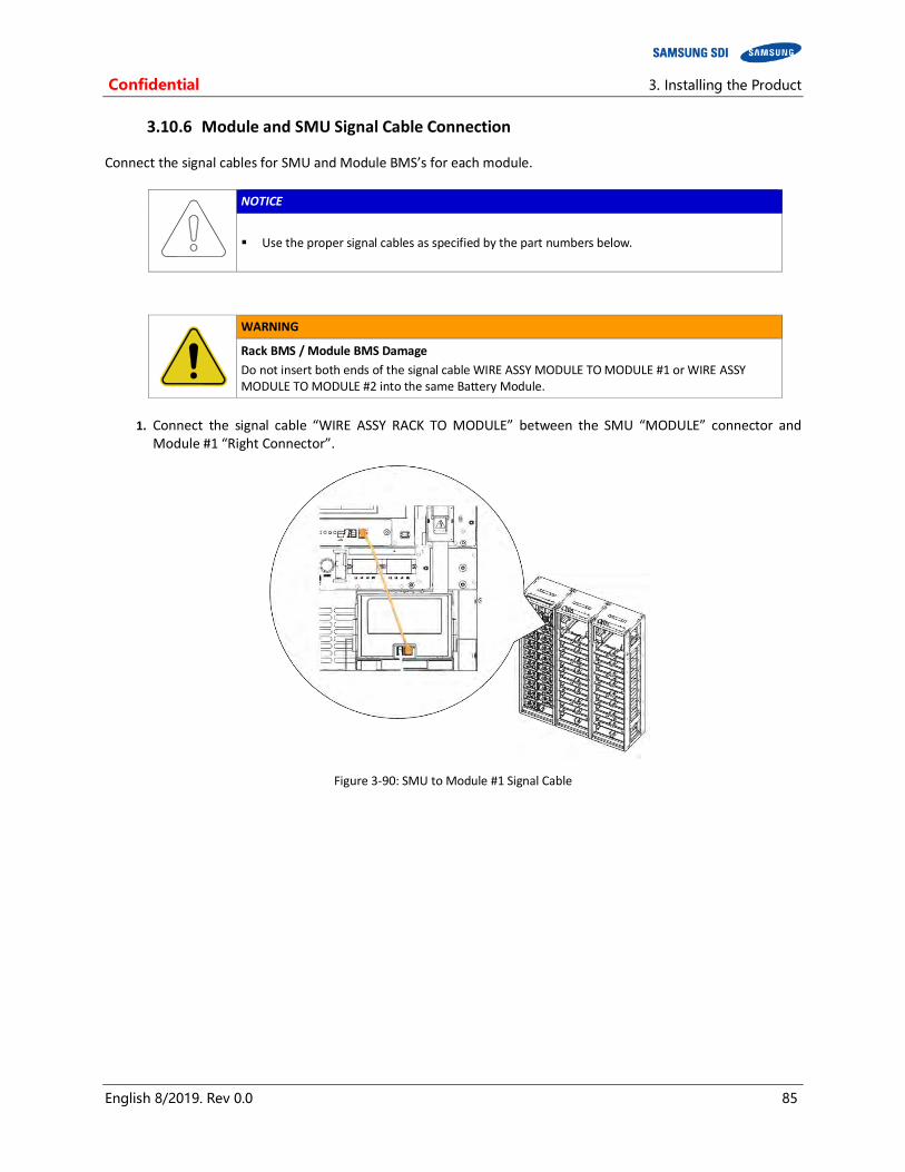
Confidential 3. Installing the Product
English 8/2019. Rev 0.0 85
3.10.6 Module and SMU Signal Cable Connection
Connect the signal cables for SMU and Module BMS’s for each module.
NOTICE
Use the proper signal cables as specified by the part numbers below.
WARNING
Rack BMS / Module BMS Damage
Do not insert both ends of the signal cable WIRE ASSY MODULE TO MODULE #1 or WIRE ASSY MODULE TO MODULE #2 into the same Battery Module.
1. Connect the signal cable “WIRE ASSY RACK TO MODULE” between the SMU “MODULE” connector and
Module #1 “Right Connector”.
Figure 3-90: SMU to Module #1 Signal Cable
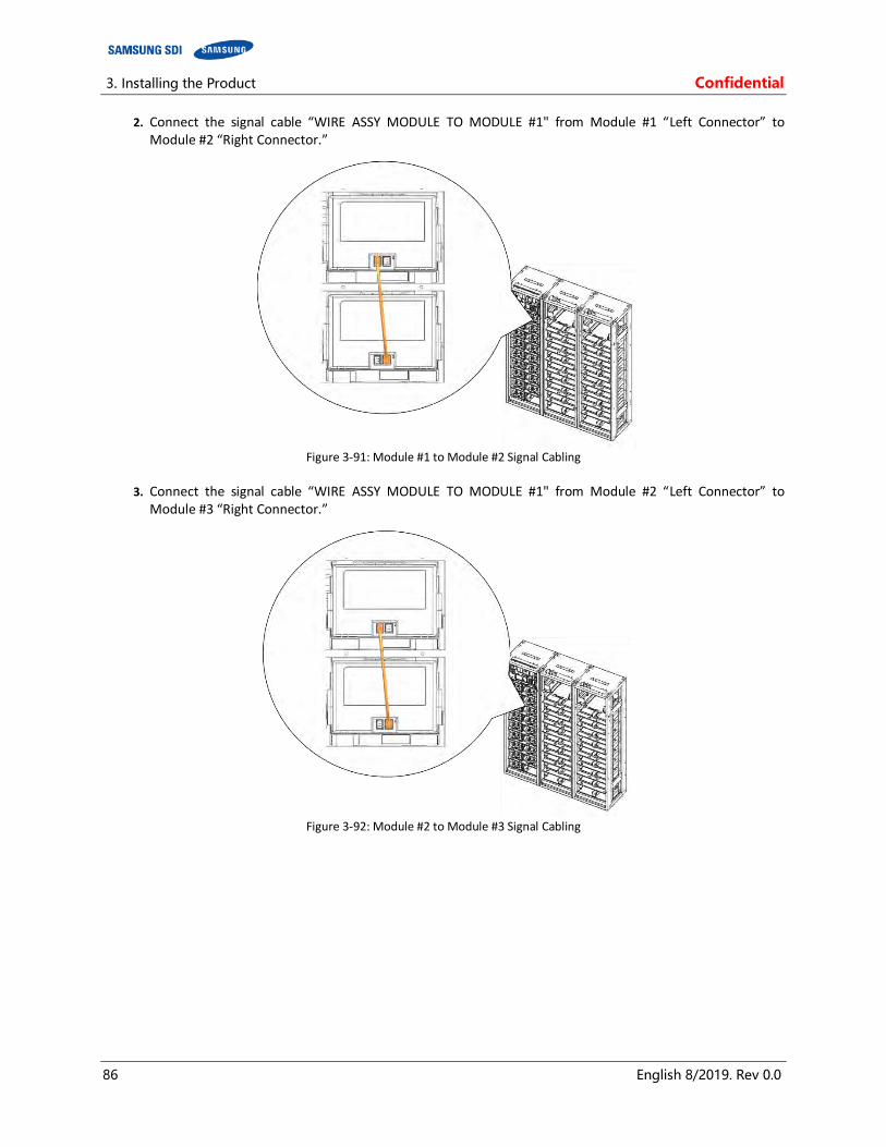
3. Installing the Product Confidential
86 English 8/2019. Rev 0.0
2. Connect the signal cable “WIRE ASSY MODULE TO MODULE #1" from Module #1 “Left Connector” to Module #2 “Right Connector.”
Figure 3-91: Module #1 to Module #2 Signal Cabling
3. Connect the signal cable “WIRE ASSY MODULE TO MODULE #1" from Module #2 “Left Connector” to
Module #3 “Right Connector.”
Figure 3-92: Module #2 to Module #3 Signal Cabling

Confidential 3. Installing the Product
English 8/2019. Rev 0.0 87
4. Connect the signal cable “WIRE ASSY MODULE TO MODULE #1" from Module #3 “Left Connector” to Module #4 “Right Connector.”
Figure 3-93: Module #3 to Module #4 Signal Cabling
5. Connect the signal cable “WIRE ASSY MODULE TO MODULE #1" from Module #4 “Left Connector” to Module #5 “Right Connector.”
Figure 3-94: Module #4 to Module #5 Signal Cabling
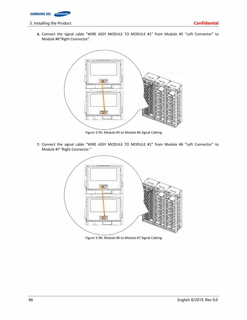
3. Installing the Product Confidential
88 English 8/2019. Rev 0.0
6. Connect the signal cable “WIRE ASSY MODULE TO MODULE #1" from Module #5 “Left Connector” to Module #6“Right Connector”.
Figure 3-95: Module #5 to Module #6 Signal Cabling
7. Connect the signal cable “WIRE ASSY MODULE TO MODULE #1" from Module #6 “Left Connector” to Module #7 “Right Connector.”
Figure 3-96: Module #6 to Module #7 Signal Cabling

Confidential 3. Installing the Product
English 8/2019. Rev 0.0 89
8. Connect the signal cable “WIRE ASSY MODULE TO MODULE #1" from Module #7 “Left connector” to Module #8 “Right connector”.
Figure 3-97: Module #7 to Module #8 Signal Cabling
9. Connect the signal cable “WIRE ASSY MODULE TO MODULE #2" from Module #8 “Left Connector” to
Module #9 “Right Connector.”
Figure 3-98: Module #8 to Module #9 Signal Cabling

3. Installing the Product Confidential
90 English 8/2019. Rev 0.0
10. Connect the signal cable “WIRE ASSY MODULE TO MODULE #1" from Module #9 “Left Connector” to Module #10 “Right Connector.”
Figure 3-99: Module #9 to Module #10 Signal Cabling
11. Connect the signal cable “WIRE ASSY MODULE TO MODULE #1" from Module #10 “Left Connector” to
Module #11 “Right Connector.”
Figure 3-100: Module #10 to Module #11 Signal Cabling
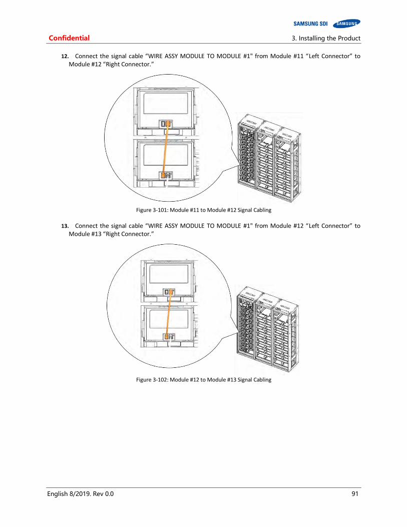
Confidential 3. Installing the Product
English 8/2019. Rev 0.0 91
12. Connect the signal cable “WIRE ASSY MODULE TO MODULE #1" from Module #11 “Left Connector” to Module #12 “Right Connector.”
Figure 3-101: Module #11 to Module #12 Signal Cabling
13. Connect the signal cable “WIRE ASSY MODULE TO MODULE #1" from Module #12 “Left Connector” to
Module #13 “Right Connector.”
Figure 3-102: Module #12 to Module #13 Signal Cabling
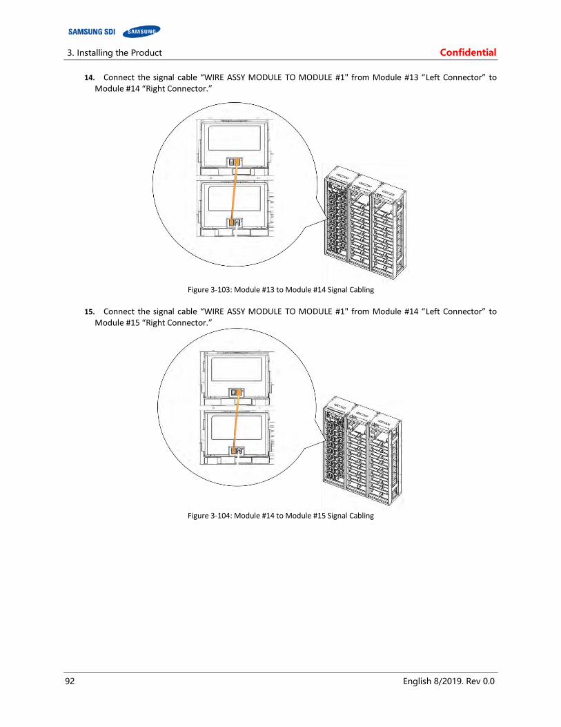
3. Installing the Product Confidential
92 English 8/2019. Rev 0.0
14. Connect the signal cable “WIRE ASSY MODULE TO MODULE #1" from Module #13 “Left Connector” to Module #14 “Right Connector.”
Figure 3-103: Module #13 to Module #14 Signal Cabling
15. Connect the signal cable “WIRE ASSY MODULE TO MODULE #1" from Module #14 “Left Connector” to
Module #15 “Right Connector.”
Figure 3-104: Module #14 to Module #15 Signal Cabling
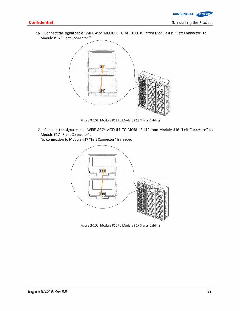
Confidential 3. Installing the Product
English 8/2019. Rev 0.0 93
16. Connect the signal cable “WIRE ASSY MODULE TO MODULE #1" from Module #15 “Left Connector” to Module #16 “Right Connector.”
Figure 3-105: Module #15 to Module #16 Signal Cabling
17. Connect the signal cable “WIRE ASSY MODULE TO MODULE #1" from Module #16 “Left Connector” to
Module #17 “Right Connector”. No connection to Module #17 “Left Connector” is needed.
Figure 3-106: Module #16 to Module #17 Signal Cabling

3. Installing the Product Confidential
94 English 8/2019. Rev 0.0
18. For a multiple rack system, connect the signal cables “WIRE ASSY RACK TO RACK #2” between each rack’s SMU. Push the pre-punched hole to pass the cable through a circular hole in the side of the rack frame and through the opening above Module #1 and Module #16.
NOTICE
See the examples for correct signal cable wire connections for both left and right rack alignments.
Figure 3-107: Pre-Punched Hole for Signal Cable
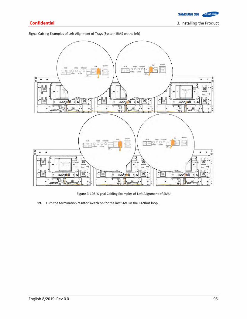
Confidential 3. Installing the Product
English 8/2019. Rev 0.0 95
Signal Cabling Examples of Left Alignment of Trays (System BMS on the left)
Figure 3-108: Signal Cabling Examples of Left Alignment of SMU
19. Turn the termination resistor switch on for the last SMU in the CANbus loop.

3. Installing the Product Confidential
96 English 8/2019. Rev 0.0
Figure 3-109: Termination Resistor Setting for Last SMU
.
NOTICE
Factory-provided cables are adequate for systems with Rack Frames bolted together. Different configurations may require cable length modification.
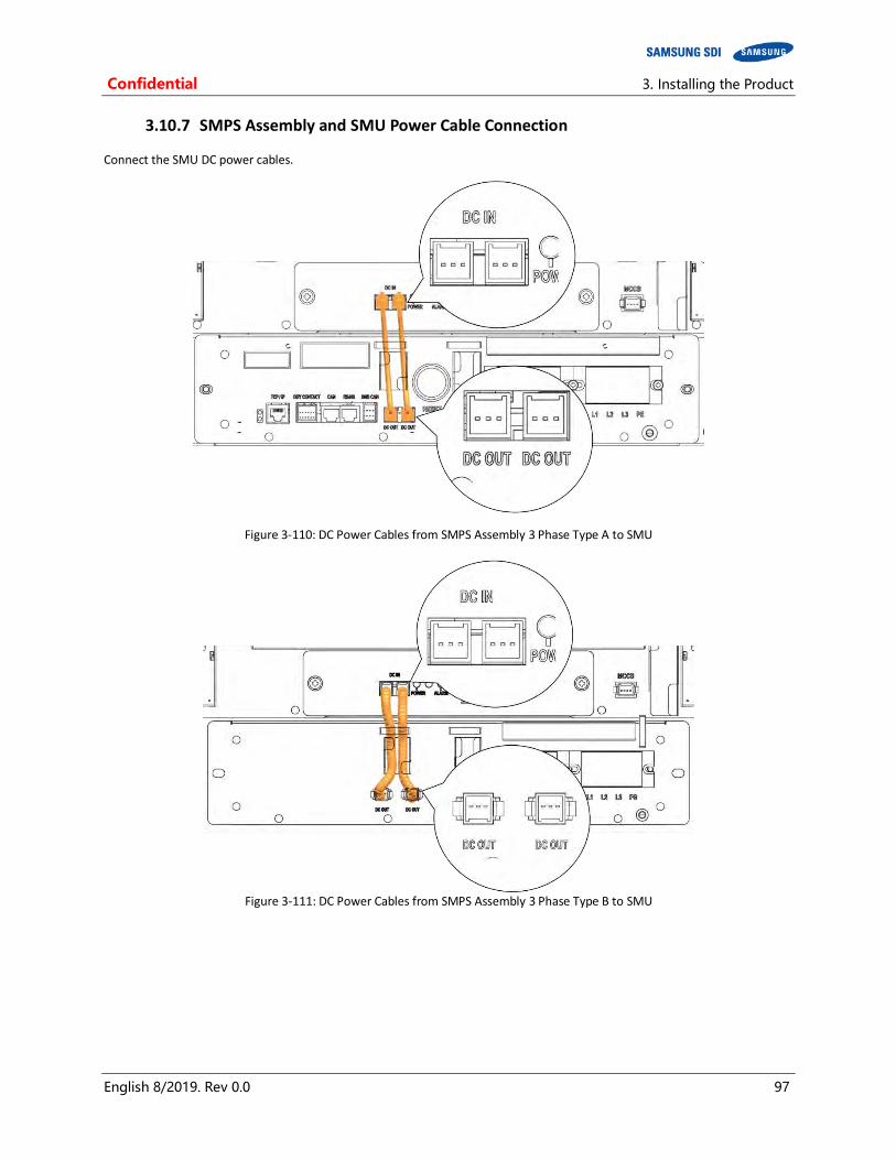
Confidential 3. Installing the Product
English 8/2019. Rev 0.0 97
3.10.7 SMPS Assembly and SMU Power Cable Connection
Connect the SMU DC power cables.
Figure 3-110: DC Power Cables from SMPS Assembly 3 Phase Type A to SMU
Figure 3-111: DC Power Cables from SMPS Assembly 3 Phase Type B to SMU

3. Installing the Product Confidential
98 English 8/2019. Rev 0.0
3.10.8 SMPS Assembly and SMU Signal Cable Connection
The following steps are only for an SMPS Assembly Type A.
1. Connect the signal cable from the SMPS Assembly to SMU “WIRE ASSY RACK TO SYSTEM.”
Figure 3-112: CAN Signal Cable Connection from SMPS Assembly 3 Phase Type A to SMU
2. Connect the MODBUS TCP/IP Cable4 to the SMPS Assembly Type A.
Figure 3-113: TCP/IP Cable Connection to SMPS Assembly
3. Connect the Dry Contact Cable to SMPS Assembly Type A
4 Not factory-provided. Must be provided by the installer or customer.
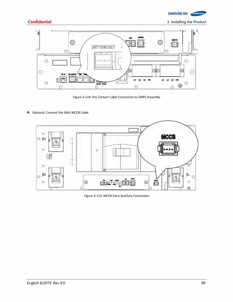
Confidential 3. Installing the Product
English 8/2019. Rev 0.0 99
Figure 3-114: Dry Contact Cable Connection to SMPS Assembly
4. Optional: Connect the SMU MCCB Cable.
Figure 3-115: MCCB Extra Auxiliary Connection
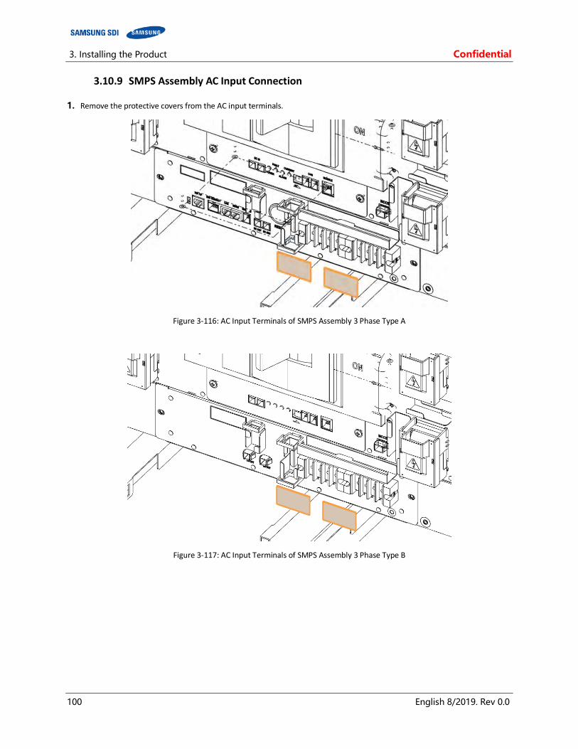
3. Installing the Product Confidential
100 English 8/2019. Rev 0.0
3.10.9 SMPS Assembly AC Input Connection
1. Remove the protective covers from the AC input terminals.
Figure 3-116: AC Input Terminals of SMPS Assembly 3 Phase Type A
Figure 3-117: AC Input Terminals of SMPS Assembly 3 Phase Type B
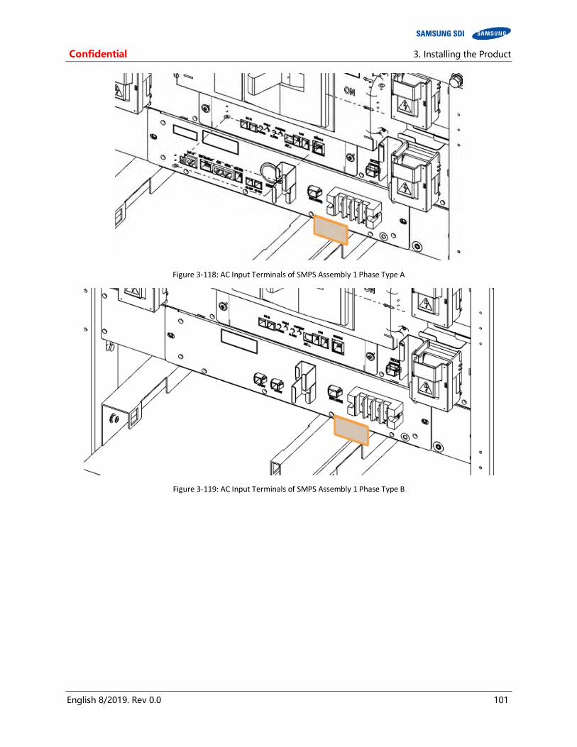
Confidential 3. Installing the Product
English 8/2019. Rev 0.0 101
Figure 3-118: AC Input Terminals of SMPS Assembly 1 Phase Type A
Figure 3-119: AC Input Terminals of SMPS Assembly 1 Phase Type B
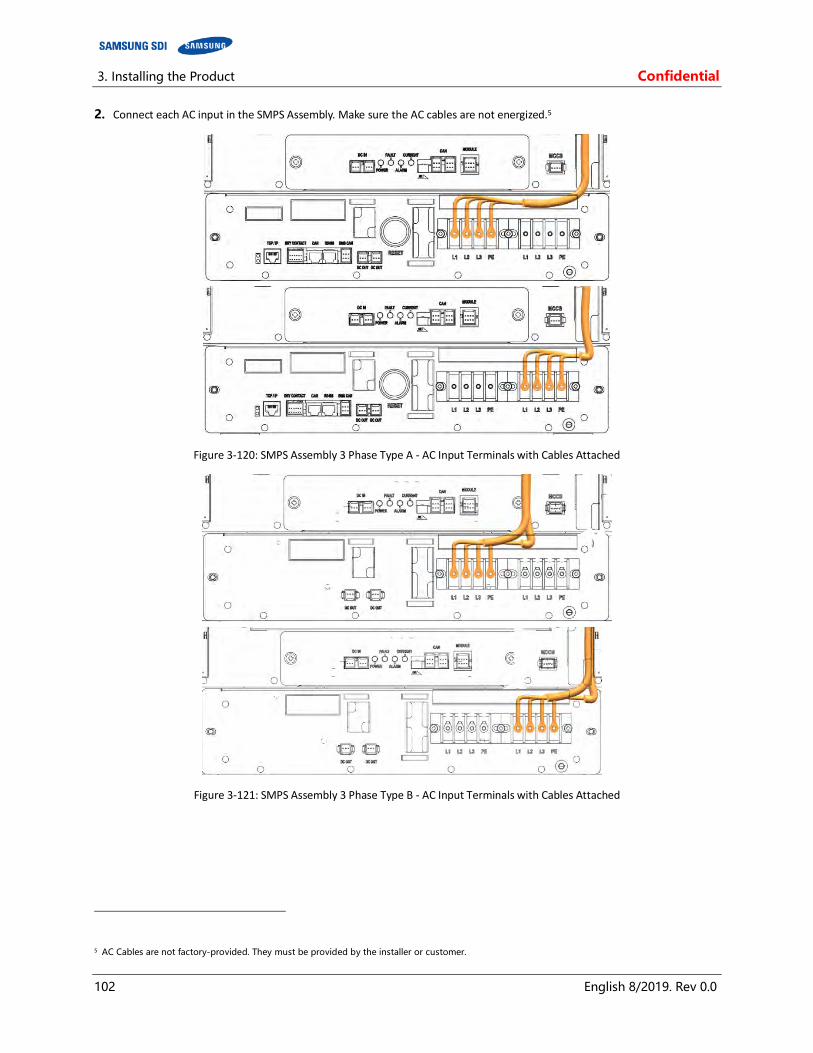
3. Installing the Product Confidential
102 English 8/2019. Rev 0.0
2. Connect each AC input in the SMPS Assembly. Make sure the AC cables are not energized.5
Figure 3-120: SMPS Assembly 3 Phase Type A - AC Input Terminals with Cables Attached
Figure 3-121: SMPS Assembly 3 Phase Type B - AC Input Terminals with Cables Attached
5 AC Cables are not factory-provided. They must be provided by the installer or customer.

Confidential 3. Installing the Product
English 8/2019. Rev 0.0 103
Figure 3-122: SMPS Assembly 1 Phase Type A - AC Input Terminals with Cables Attached
Figure 3-123: SMPS Assembly 1 Phase Type B - AC Input Terminals with Cables Attached
3. Reattach the protective covers to the AC input.
Figure 3-124: AC Input Terminals of SMPS Assembly 3 Phase Type A
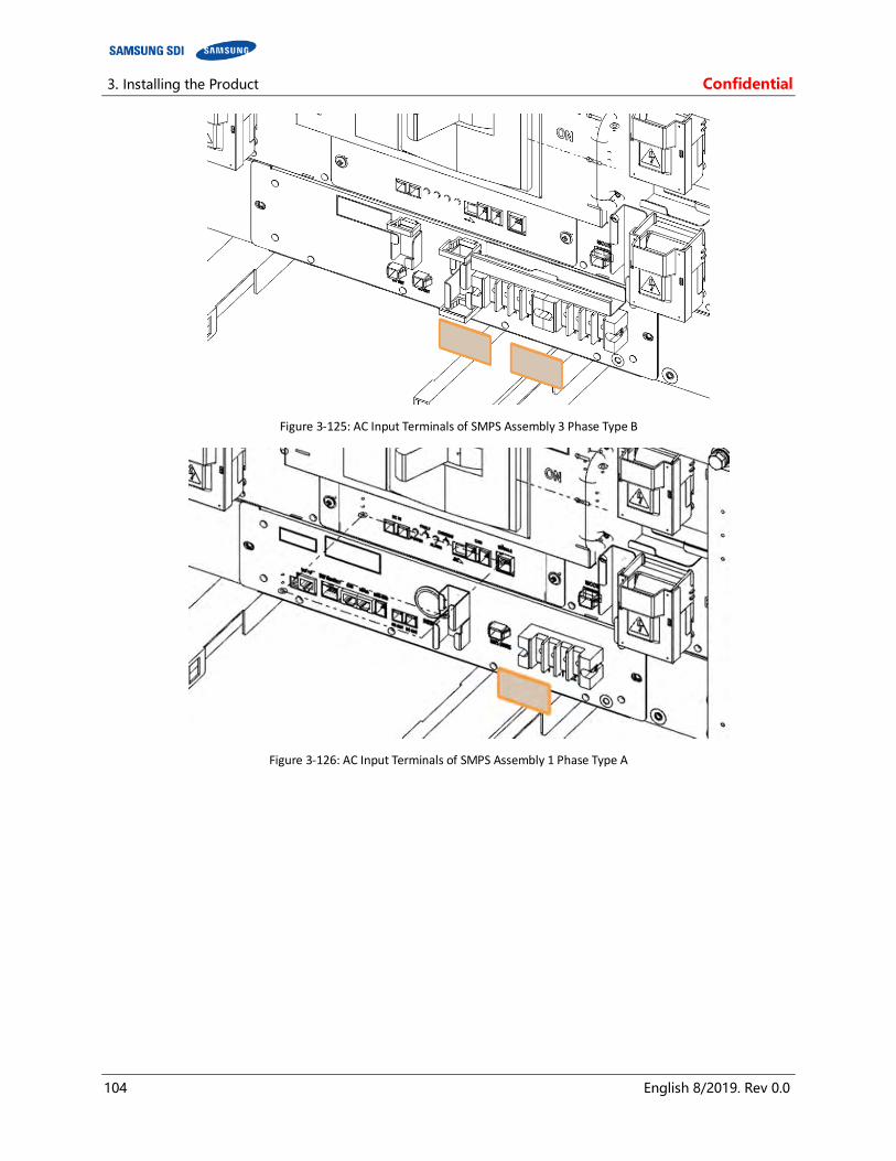
3. Installing the Product Confidential
104 English 8/2019. Rev 0.0
Figure 3-125: AC Input Terminals of SMPS Assembly 3 Phase Type B
Figure 3-126: AC Input Terminals of SMPS Assembly 1 Phase Type A
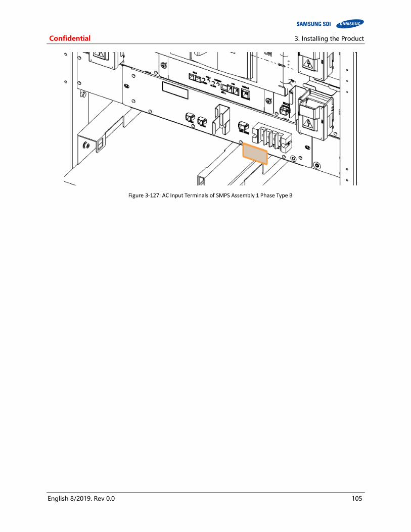
Confidential 3. Installing the Product
English 8/2019. Rev 0.0 105
Figure 3-127: AC Input Terminals of SMPS Assembly 1 Phase Type B

3. Installing the Product Confidential
106 English 8/2019. Rev 0.0
3.10.10 DC Link Cable Connection
1. Connect the ground cables.
Figure 3-128: Grounding Points (2 EA)
NOTICE
Connect the rack ground wire with an M12 screw. Rack ground screws and cables are not factory-provided and must be provided by the installer or customer.
The fastening torque should be 30Nm (300kgf∙cm).
45 mm Pitch
Between Holes
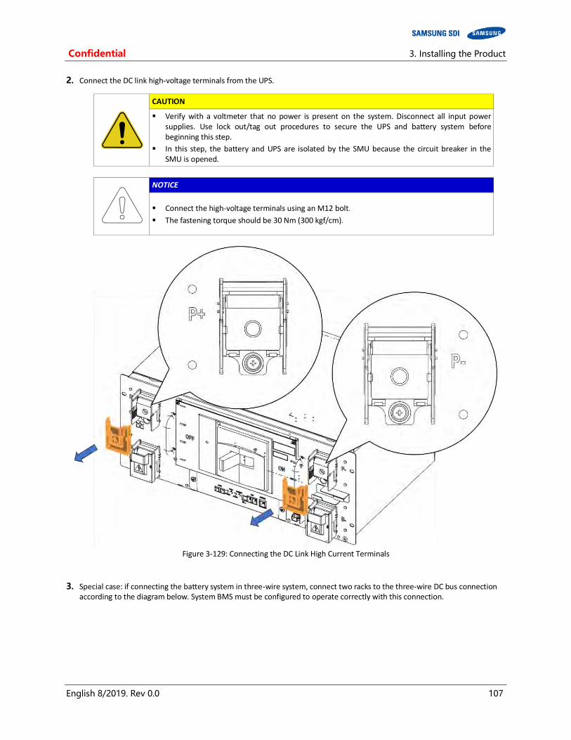
Confidential 3. Installing the Product
English 8/2019. Rev 0.0 107
2. Connect the DC link high-voltage terminals from the UPS.
CAUTION
Verify with a voltmeter that no power is present on the system. Disconnect all input power supplies. Use lock out/tag out procedures to secure the UPS and battery system before beginning this step.
In this step, the battery and UPS are isolated by the SMU because the circuit breaker in the SMU is opened.
NOTICE
Connect the high-voltage terminals using an M12 bolt.
The fastening torque should be 30 Nm (300 kgf/cm).
Figure 3-129: Connecting the DC Link High Current Terminals
3. Special case: if connecting the battery system in three-wire system, connect two racks to the three-wire DC bus connection according to the diagram below. System BMS must be configured to operate correctly with this connection.

3. Installing the Product Confidential
108 English 8/2019. Rev 0.0
After installation is complete, check the following:
Bolt fastening condition Screw fastening torque by sampling High-voltage cable connection Module connections SMU connections

Confidential 3. Installing the Product
English 8/2019. Rev 0.0 109
3.10.11 AC Input Commissioning
When the installation of the battery system is complete, SMPS Assembly’s AC inputs must be powered to turn the BMS on.

3. Installing the Product Confidential
110 English 8/2019. Rev 0.0
3.10.12 BMS Configuration
NOTICE
It is recommended that the configuration of the Rack BMS and System BMS be done by experienced service personnel. Incorrect configuration of the Rack BMS and System BMS will cause communication failure.
Prepare the following items and configure the Rack BMS and System BMS.
Table 3-10: Required Items for BMS Configuration
No. Items Appearance Comments
1 Rack BMS Configuration Cable
J21SF-06V-KX-L (6 pin) and D-SUB female (9 pin)
Connect between Rack BMS and USB-to-CAN device.
Must be made by customer or installer as described below
(Table 3-11: Rack BMS Configuration Cable Pin Map)
2 System BMS Configuration Cable
RJ45 (8 pin) and D-SUB female (9 pin)
Connect between System BMS and USB-to-CAN device
Must be made by the customer or installer as described below
(Table 3-12: System BMS Configuration Cable Pin Map)
3 Ethernet Cable
RJ45 (8 pin) and RJ45 (8 pin)
Must be made by the customer or installer as described below
(Table 3-13: System BMS Communication Cable Pin Map)
4 IXXAT USB-to-CAN V2
Must be provided by the customer or installer.
Driver must be installed on the computer.
5 Computer
Windows 7 or later
Must be provided by customer or installer.
Minimum hardware requirements
CPU: Core i5 or higher
RAM: Over 4 GB RAM
Hard disk space: over 6MB of free space
Ethernet: wired LAN with 1Gbps
USB Port: USB 2.0 (480Mbps) or faster
Software requirements
Microsoft .Net Framework 4.5.1
VCI V3 Driver 3.5.4 Download link: https://www.ixxat.com/docs/librariesprovider8/default-document-library/downloads/vci-v3/vci_3_5_4_4543.exe?sfvrsn=10

Confidential 3. Installing the Product
English 8/2019. Rev 0.0 111
NOTICE
The Rack BMS configuration cable, System BMS configuration cable and Ethernet cable must be made by the customer or installer according to the following PIN map.
Figure 3-130: Rack BMS Configuration Cable Pin Map
Table 3-11: Rack BMS Configuration Cable Pin Map
Connection A Connection B
Connector Pin No. Signal Connector Pin No. Signal
D-SUB (Female)
1 -
J21SF-06V-KX-L
1A GND Ground
2 CAN Low 2A -
3 CAN Ground 3A -
4 - 1B CAN Low
5 - 2B CAN High
6 - 3B -
7 CAN High
8 -
9 -
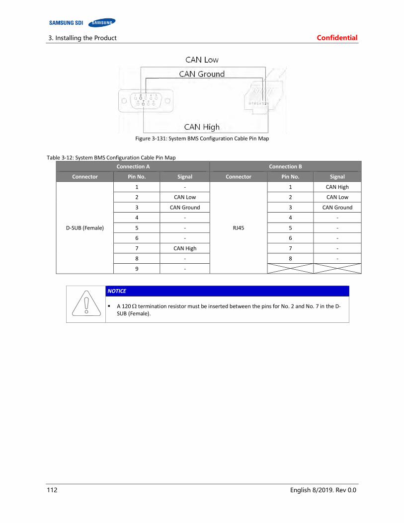
3. Installing the Product Confidential
112 English 8/2019. Rev 0.0
Figure 3-131: System BMS Configuration Cable Pin Map
Table 3-12: System BMS Configuration Cable Pin Map
Connection A Connection B
Connector Pin No. Signal Connector Pin No. Signal
D-SUB (Female)
1 -
RJ45
1 CAN High
2 CAN Low 2 CAN Low
3 CAN Ground 3 CAN Ground
4 - 4 -
5 - 5 -
6 - 6 -
7 CAN High 7 -
8 - 8 -
9 -
NOTICE
A 120 termination resistor must be inserted between the pins for No. 2 and No. 7 in the D-SUB (Female).
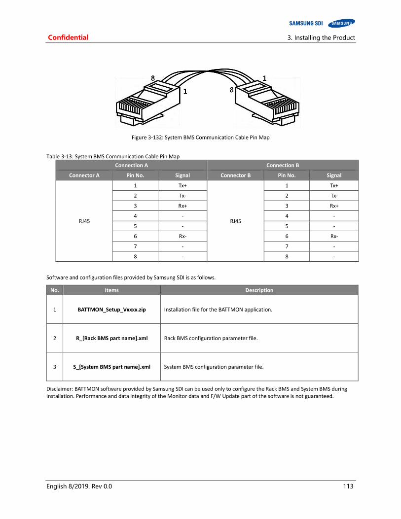
Confidential 3. Installing the Product
English 8/2019. Rev 0.0 113
Figure 3-132: System BMS Communication Cable Pin Map
Table 3-13: System BMS Communication Cable Pin Map
Connection A Connection B
Connector A Pin No. Signal Connector B Pin No. Signal
RJ45
1 Tx+
RJ45
1 Tx+
2 Tx- 2 Tx-
3 Rx+ 3 Rx+
4 - 4 -
5 - 5 -
6 Rx- 6 Rx-
7 - 7 -
8 - 8 -
Software and configuration files provided by Samsung SDI is as follows.
No. Items Description
1 BATTMON_Setup_Vxxxx.zip Installation file for the BATTMON application.
2 R_[Rack BMS part name].xml Rack BMS configuration parameter file.
3 S_[System BMS part name].xml System BMS configuration parameter file.
Disclaimer: BATTMON software provided by Samsung SDI can be used only to configure the Rack BMS and System BMS during installation. Performance and data integrity of the Monitor data and F/W Update part of the software is not guaranteed.

3. Installing the Product Confidential
114 English 8/2019. Rev 0.0
3.10.12.1 BATTMON Installation and setup
1. Follow the steps below for installing BATTMON program.
① Unzip the provided compressed file.
② Locate the unzipped folder
③ Locate and open “setup.exe”
④ Click “Next” to continue.
⑤ Check the folder setting and click “Next” to continue
⑥ Click “Next” to continue.
⑦ Check the installation progress.
⑧ Click “Close” to finish installation.
⑨ Locate and open “BATTMON”

Confidential 3. Installing the Product
English 8/2019. Rev 0.0 115
2. Follow the steps below to configure the BATTMON to installation mode
① Double click the icon on the upper left part of the BATTMON window.
Figure 3-133: BATTMON Splash Window
② When prompted for a password, enter “install” (not case sensitive) and press enter.
Figure 3-134: Installer Access Password
③ Click the “Add parameter file” icon under the SYSTEM BMS part to add the System BMS parameter files.

3. Installing the Product Confidential
116 English 8/2019. Rev 0.0
Figure 3-135: BATTMON Splash Window
④ Press “OK” to skip the warning.
Figure 3-136: Warning Pop-up Window
⑤ Find and select the System BMS parameter file. Click “Open” to load the file to BATTMON.
Figure 3-137: Selecting System BMS Configuration Parameter File
⑥ Click the “Add parameter file” icon under the RACK BMS part to add the Rack BMS parameter files.

Confidential 3. Installing the Product
English 8/2019. Rev 0.0 117
Figure 3-138: BATTMON Splash Window : Warning Pop-up Window
⑦ Press “OK” to skip the warning.
Figure 3-139: Warning Pop-up Window
⑧ Find and select the Rack BMS parameter file. Click “Open” to load the file to BATTMON.
Figure 3-140: Selecting Rack BMS Configuration Parameter File
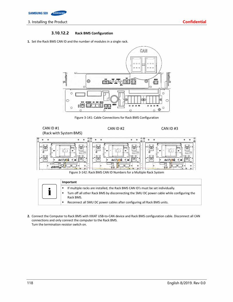
3. Installing the Product Confidential
118 English 8/2019. Rev 0.0
3.10.12.2 Rack BMS Configuration
1. Set the Rack BMS CAN ID and the number of modules in a single rack.
Figure 3-141: Cable Connections for Rack BMS Configuration
Figure 3-142: Rack BMS CAN ID Numbers for a Multiple Rack System
Important
If multiple racks are installed, the Rack BMS CAN ID’s must be set individually.
Turn off all other Rack BMS by disconnecting the SMU DC power cable while configuring the Rack BMS.
Reconnect all SMU DC power cables after configuring all Rack BMS units.
2. Connect the Computer to Rack BMS with IXXAT USB-to-CAN device and Rack BMS configuration cable. Disconnect all CAN connections and only connect the computer to the Rack BMS. Turn the termination resistor switch on.
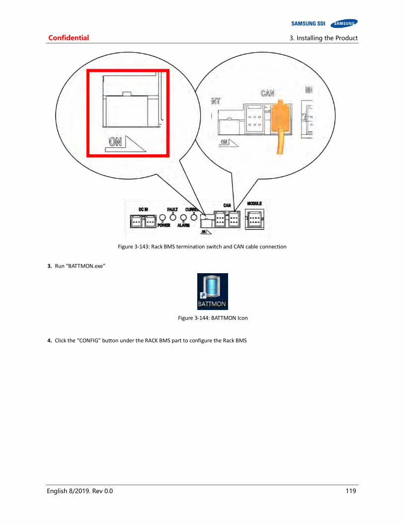
Confidential 3. Installing the Product
English 8/2019. Rev 0.0 119
Figure 3-143: Rack BMS termination switch and CAN cable connection
3. Run “BATTMON.exe”
Figure 3-144: BATTMON Icon
4. Click the “CONFIG” button under the RACK BMS part to configure the Rack BMS

3. Installing the Product Confidential
120 English 8/2019. Rev 0.0
Figure 3-145: BATTMON Splash Window
5. Select the CAN [IXXAT] device from the list and click “Connect”. If no device is shown, disconnect the IXXAT USB-to-CAN device from the computer and reinstall the device driver.
Figure 3-146: Rack BMS - CONFIG connection window
NOTICE
When the USB-to-CAN device is not connected to your computer, the CONNECT button will not work.
6. Select “RACK #001” from the drop-down menu. This is the factory default setting. - Click on the checkbox to write the value. - Double-click the values under “Write Value” column to change the write values. - For CAN ID #1, write value is 0x2001. For CAN ID #2, the value is 0x2002. - Write the number of module BMS per rack. In case of 136S battery, the number of module BMS is 17. (8 cells per module BMS) - Click “[WRITE] To BMS B’d” button to write the checked values to the Rack BMS. - Click “APPLY [BMS RESET]” to reset the BMS with the written parameters.
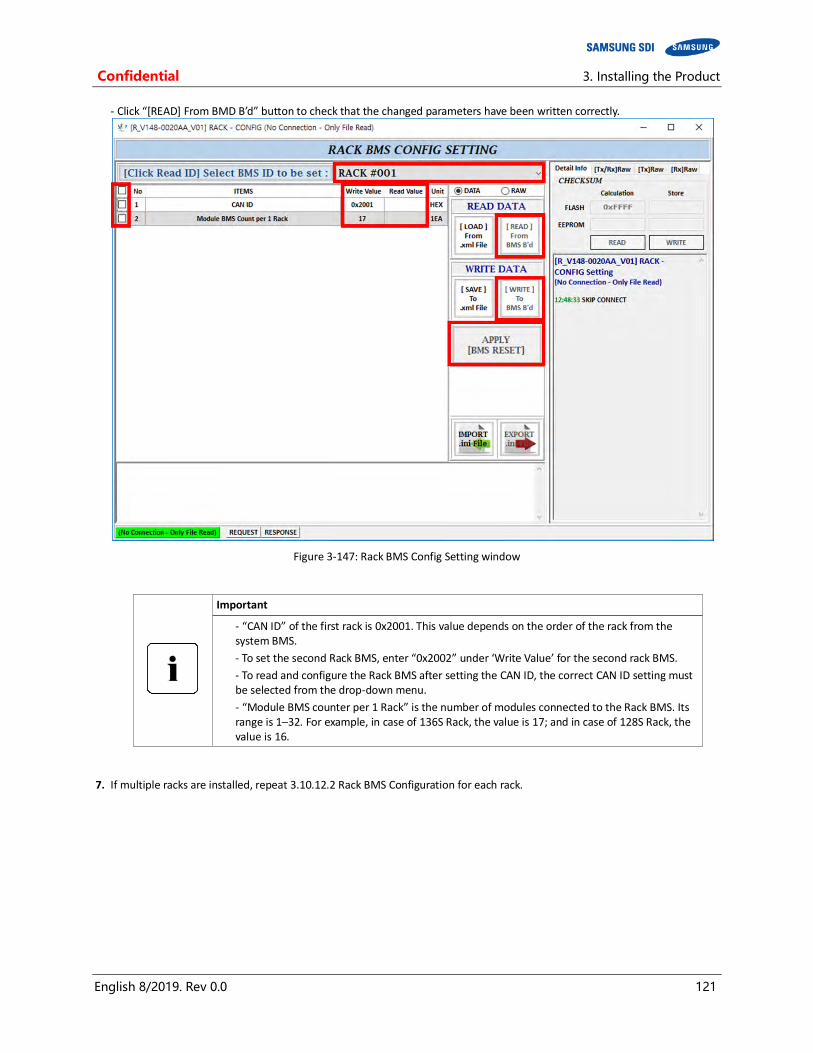
Confidential 3. Installing the Product
English 8/2019. Rev 0.0 121
- Click “[READ] From BMD B’d” button to check that the changed parameters have been written correctly.
Figure 3-147: Rack BMS Config Setting window
Important
- “CAN ID” of the first rack is 0x2001. This value depends on the order of the rack from the system BMS.
- To set the second Rack BMS, enter “0x2002” under ‘Write Value’ for the second rack BMS.
- To read and configure the Rack BMS after setting the CAN ID, the correct CAN ID setting must be selected from the drop-down menu.
- “Module BMS counter per 1 Rack” is the number of modules connected to the Rack BMS. Its range is 1–32. For example, in case of 136S Rack, the value is 17; and in case of 128S Rack, the value is 16.
7. If multiple racks are installed, repeat 3.10.12.2 Rack BMS Configuration for each rack.

3. Installing the Product Confidential
122 English 8/2019. Rev 0.0
3.10.12.3 System BMS Configuration
1. Connect both an Ethernet cable and a configuration cable from the system BMS to your computer as shown in the figure below.
Figure 3-148: Cable Connections for System BMS Configuration
2. Run “BATTMON.exe”
Figure 3-149: BATTMON Icon
3. Click the “CONFIG” button under the SYSTEM BMS part to configure the System BMS
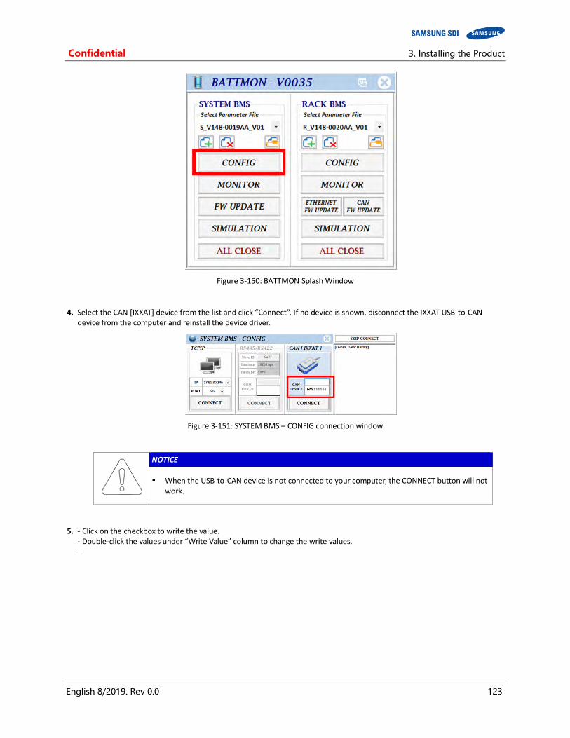
Confidential 3. Installing the Product
English 8/2019. Rev 0.0 123
Figure 3-150: BATTMON Splash Window
4. Select the CAN [IXXAT] device from the list and click “Connect”. If no device is shown, disconnect the IXXAT USB-to-CAN device from the computer and reinstall the device driver.
Figure 3-151: SYSTEM BMS – CONFIG connection window
NOTICE
When the USB-to-CAN device is not connected to your computer, the CONNECT button will not work.
5. - Click on the checkbox to write the value. - Double-click the values under “Write Value” column to change the write values. -

3. Installing the Product Confidential
124 English 8/2019. Rev 0.0
Figure 3-152: System BMS Install Setting Window
Important
Change the values according to your system configuration.
[Count] Rack per 1 System: Number of racks connected to the same System BMS
[Count] Module per 1 Rack: Number of modules for each rack (e.g., 136S1P Rack has 17 modules)
[TCPIP] items (IP Address, Subnet Mask, Gateway, Port)
TCP/IP address and port (17.91.30.246/502 by default), subnet mask (255.255.224.0 by default) and gateway (17.91.1.2 by default) should be changed according to your network environment.
Set the port number to the factory default values (Port#01: 502, Port#02: 602, Port#03: 702)
[RTU] items: set to the factory default values.
(Baud rate: 0, Parity: 1, Slave ID: 0x27)
[Operation] Neutral Control Enable
Set to “0” if all racks are connected in parallel (default). Set to “1” if the two racks are connected in series for a three-wire connection.
[Operation] Customer ID
Set according to the dry contact input and output options. Refer to 2.1.3 SMPS Assembly (Type A / Type B)

Confidential 3. Installing the Product
English 8/2019. Rev 0.0 125
3.10.13 Communication Check
After installation, wiring, and configuration are completed, check the communication status by connecting the TCP/IP cable and run the MODBUS program to see whether the System BMS shows the data of the Rack BMS correctly.
3.10.13.1 PC’s IP Setting for Communication with the System BMS
NOTICE
The following guide for PC’s IP setting is made with Microsoft® Windows® 7. Other versions of Windows may be different.
1. Checking the Data of the System BMS requires changing the IP settings in the notebook PC to be used.
2. Click the “START” button in the desktop’s status bar (①) to open the Start menu.
3. Click “Network” (②). If “Network” menu is not available, click “Control Panel”
Figure 3-153: Open “Network”
4. When the Network window appears, click “Network and Sharing Center” (③).
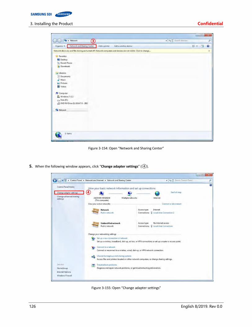
3. Installing the Product Confidential
126 English 8/2019. Rev 0.0
Figure 3-154: Open “Network and Sharing Center”
5. When the following window appears, click “Change adapter settings” (④).
Figure 3-155: Open “Change adapter settings”
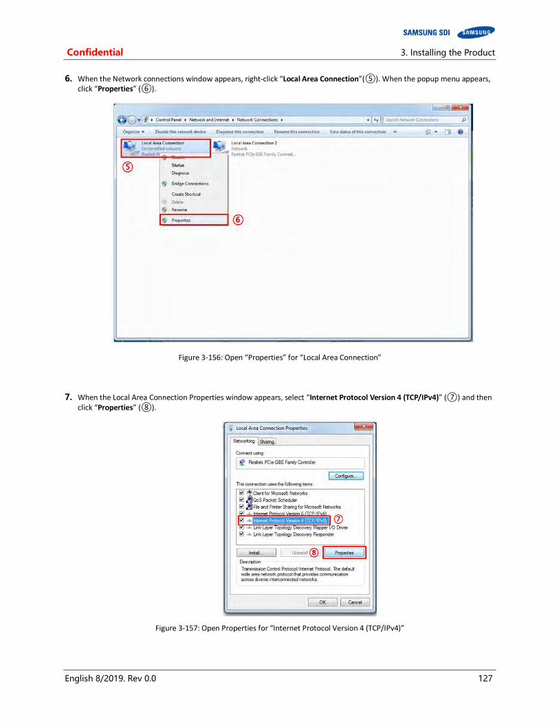
Confidential 3. Installing the Product
English 8/2019. Rev 0.0 127
6. When the Network connections window appears, right-click “Local Area Connection”(⑤). When the popup menu appears, click “Properties” (⑥).
Figure 3-156: Open “Properties” for “Local Area Connection”
7. When the Local Area Connection Properties window appears, select “Internet Protocol Version 4 (TCP/IPv4)” (⑦) and then click “Properties” (⑧).
Figure 3-157: Open Properties for “Internet Protocol Version 4 (TCP/IPv4)”
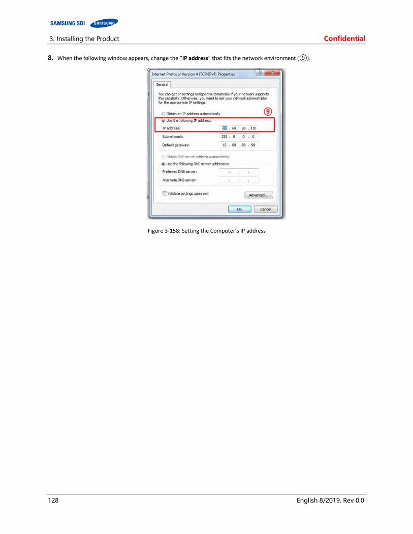
3. Installing the Product Confidential
128 English 8/2019. Rev 0.0
8. When the following window appears, change the “IP address” that fits the network environment (⑨).
Figure 3-158: Setting the Computer’s IP address
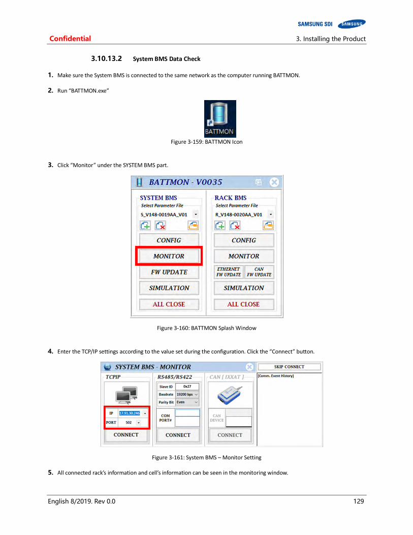
Confidential 3. Installing the Product
English 8/2019. Rev 0.0 129
3.10.13.2 System BMS Data Check
1. Make sure the System BMS is connected to the same network as the computer running BATTMON.
2. Run “BATTMON.exe”
Figure 3-159: BATTMON Icon
3. Click “Monitor” under the SYSTEM BMS part.
Figure 3-160: BATTMON Splash Window
4. Enter the TCP/IP settings according to the value set during the configuration. Click the “Connect” button.
Figure 3-161: System BMS – Monitor Setting
5. All connected rack’s information and cell’s information can be seen in the monitoring window.
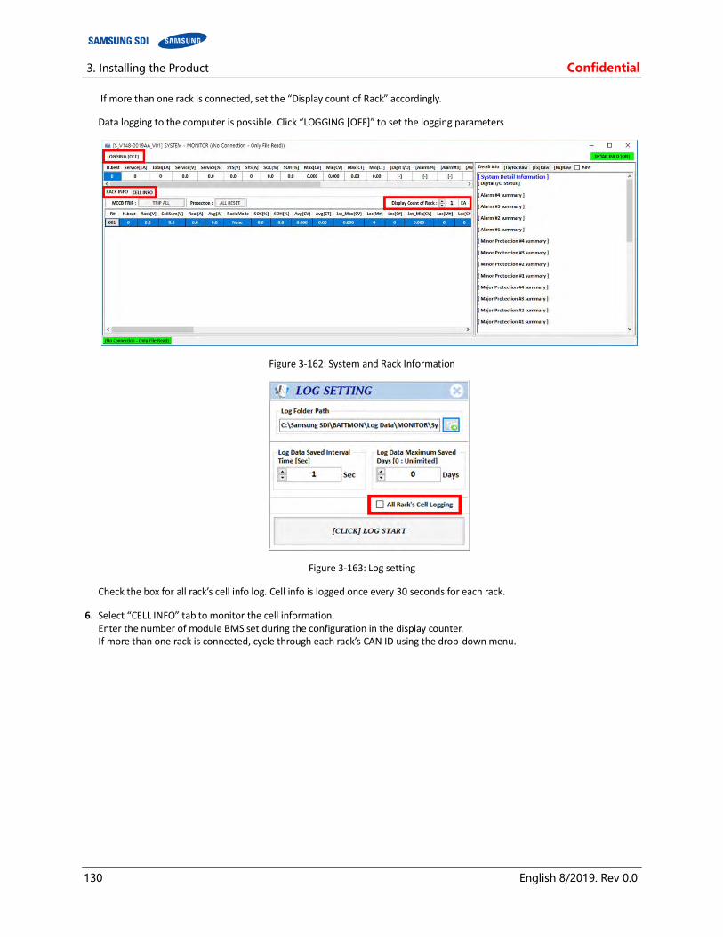
3. Installing the Product Confidential
130 English 8/2019. Rev 0.0
If more than one rack is connected, set the “Display count of Rack” accordingly.
Data logging to the computer is possible. Click “LOGGING [OFF]” to set the logging parameters
Figure 3-162: System and Rack Information
Figure 3-163: Log setting
Check the box for all rack’s cell info log. Cell info is logged once every 30 seconds for each rack.
6. Select “CELL INFO” tab to monitor the cell information. Enter the number of module BMS set during the configuration in the display counter. If more than one rack is connected, cycle through each rack’s CAN ID using the drop-down menu.
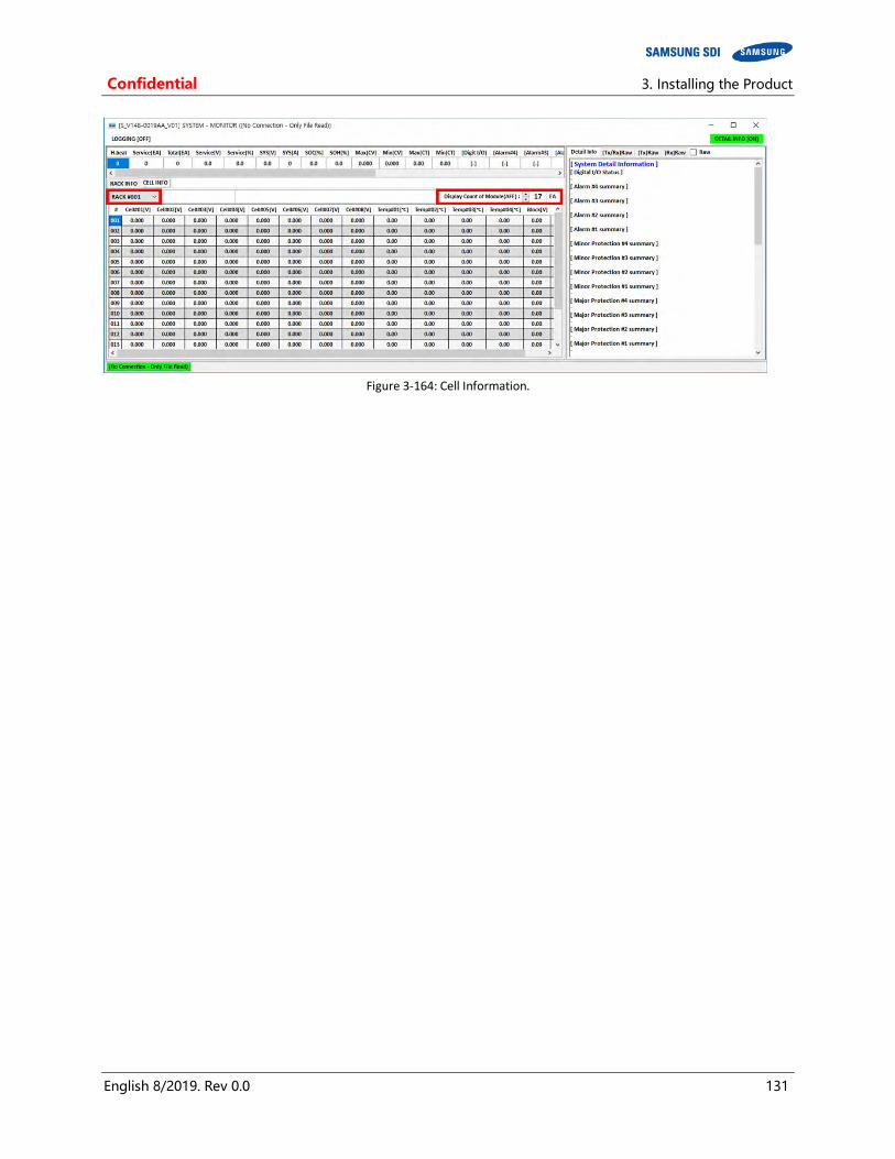
Confidential 3. Installing the Product
English 8/2019. Rev 0.0 131
Figure 3-164: Cell Information.
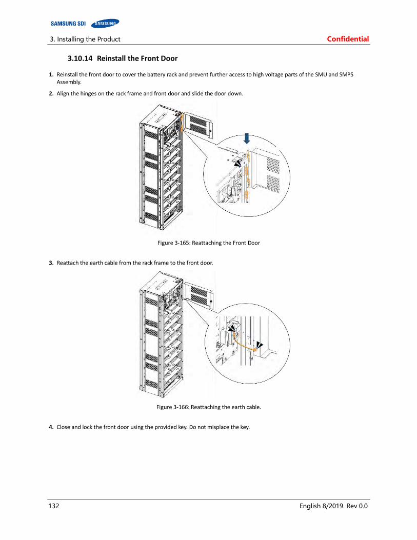
3. Installing the Product Confidential
132 English 8/2019. Rev 0.0
3.10.14 Reinstall the Front Door
1. Reinstall the front door to cover the battery rack and prevent further access to high voltage parts of the SMU and SMPS Assembly.
2. Align the hinges on the rack frame and front door and slide the door down.
Figure 3-165: Reattaching the Front Door
3. Reattach the earth cable from the rack frame to the front door.
Figure 3-166: Reattaching the earth cable.
4. Close and lock the front door using the provided key. Do not misplace the key.
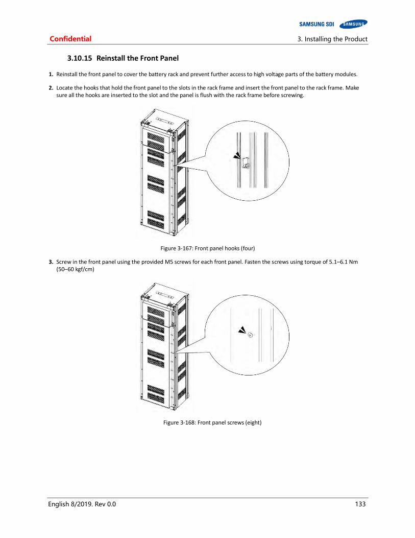
Confidential 3. Installing the Product
English 8/2019. Rev 0.0 133
3.10.15 Reinstall the Front Panel
1. Reinstall the front panel to cover the battery rack and prevent further access to high voltage parts of the battery modules.
2. Locate the hooks that hold the front panel to the slots in the rack frame and insert the front panel to the rack frame. Make sure all the hooks are inserted to the slot and the panel is flush with the rack frame before screwing.
Figure 3-167: Front panel hooks (four)
3. Screw in the front panel using the provided M5 screws for each front panel. Fasten the screws using torque of 5.1–6.1 Nm (50–60 kgf/cm)
Figure 3-168: Front panel screws (eight)

3. Installing the Product Confidential
134 English 8/2019. Rev 0.0
3.10.16 Switching on the MCCB
After powering on the battery system’s SMPS Assembly and SMU, and configuring the System BMS and the Rack BMS according to the installation, check the indicator LED to determine whether the system status is normal. Refer to the “Product Specification” and “Operation and Maintenance Manual” for information on the indicator LED.
CAUTION
Follow the instruction and guidelines for the UPS on connecting the battery to the UPS before switching on the MCCB.
The MCCB in the SMU should be in the “TRIP” position during installation.
Figure 3-169: MCCB Handle in Trip Position
Shift the handle of the MCCB to “OFF.”
Figure 3-170: MCCB Handle in Off Position
Then shift the handle to “ON” to connect the battery system to the UPS DC link.
Figure 3-171: MCCB Handle in On Position

Confidential
Memo

Confidential
Memo

Confidential
Memo

www.SamsungSDI.com