Embed Size (px)
Citation preview

LGS UFSAR
CHAPTER 08 8-i REV. 16, SEPTEMBER 2012
CHAPTER 8 - ELECTRIC POWER
TABLE OF CONTENTS
8.1 INTRODUCTION
8.1.1 General8.1.2 Utility Power Grid and Offsite Power Systems8.1.3 Onsite Power Systems8.1.4 Safety-Related Loads8.1.5 Design Bases8.1.5.1 Offsite Power System8.1.5.2 Onsite Power System8.1.6 Regulatory Guides and IEEE Standards8.1.6.1 Conformance with Regulatory Guides8.1.6.1.1 Regulatory Guide 1.6 (March 1971) - Independence Between Redundant
Standby (Onsite) Power Sources and Between Their Distribution Systems (Safety Guide 6)
8.1.6.1.2 Regulatory Guide 1.9 (March 1971) - Selection of Diesel Generator Set Capacity for Standby Power Supplies (Safety Guide 9)
8.1.6.1.3 Regulatory Guide 1.22 (February 1972) - Periodic Testing of Protection System Actuation Functions (Safety Guide 22)
8.1.6.1.4 Regulatory Guide 1.29 (February 1978) - Seismic Design Classification8.1.6.1.5 Regulatory Guide 1.30 (August 1972) - Quality Assurance Requirements for the
Installation, Inspection, and Testing of Instrumentation and Electric Equipment (Safety Guide 30)
8.1.6.1.6 Regulatory Guide 1.32 (February 1977) - Criteria for Safety-Related Electric Power Systems for Nuclear Power Plants
8.1.6.1.7 Regulatory Guide 1.40 (March 1973) - Qualification Tests of Continuous-Duty Motors Installed Inside the Containment of Water-Cooled Nuclear Power Plants
8.1.6.1.8 Regulatory Guide 1.41 (March 1973) - Preoperational Testing of Redundant Onsite Electric Power Systems to Verify Proper Load Group Assignments
8.1.6.1.9 Regulatory Guide 1.47 (May 1973) - Bypassed and Inoperable Status Indication for Nuclear Power Plant Safety Systems
8.1.6.1.10 Regulatory Guide 1.53 (June 1973) - Application of the Single Failure Criterion to Nuclear Power Plant Protection Systems
8.1.6.1.11 Regulatory Guide 1.62 (October 1973) - Manual Initiation of Protective Actions8.1.6.1.12 Regulatory Guide 1.63 (October 1973 and July 1978) - Electric Penetration
Assemblies in Containment Structures for Water-Cooled Nuclear Power Plants8.1.6.1.13 Regulatory Guide 1.73 (January 1974) - Qualification Tests of Electric Valve
Operators Installed Inside the Containment of Nuclear Power Plants8.1.6.1.14 Regulatory Guide 1.75 (September 1978) - Physical Independence of Electric
Systems8.1.6.1.15 Regulatory Guide 1.81 (January 1975) - Shared Emergency and Shutdown
Electric System for Multi-Unit Nuclear Power Plants8.1.6.1.16 Regulatory Guide 1.89 (November 1974) - Qualification of Class 1E Equipment
for Nuclear Power Plants

LGS UFSAR
TABLE OF CONTENTS (Cont'd)
CHAPTER 08 8-ii REV. 16, SEPTEMBER 2012
8.1.6.1.17 Regulatory Guide 1.93 (December 1974) - Availability of Electric Power Sources8.1.6.1.18 Regulatory Guide 1.100 (August 1977) - Seismic Qualification of Electric
Equipment for Nuclear Power Plants8.1.6.1.19 Regulatory Guide 1.106 (March 1977) - Thermal Overload Protection for Electric
Motors on Motor-Operated Valves8.1.6.1.20 Regulatory Guide 1.108 (August 1977) - Periodic Testing of Diesel Generator
Units Used as Onsite Electric Power Systems at Nuclear Power Plants8.1.6.1.21 Regulatory Guide 1.118 (June 1978) - Periodic Testing of Electric Power and
Protection Systems8.1.6.1.22 Regulatory Guide 1.128 (October 1978) - Installation Design and Installation of
Large Lead Storage Batteries for Nuclear Power Plants8.1.6.1.23 Regulatory Guide 1.129 (February 1978) - Maintenance, Testing, and
Replacement of Large Lead Storage Batteries for Nuclear Power Plants8.1.6.1.24 Regulatory Guide 1.131 (August 1977) - Qualification Tests of Electric Cables,
Field Splices, and Connections for Light-Water-Cooled Nuclear Power Plants8.1.6.1.25 Regulatory Guide 1.155 (June 1988) - Station Blackout8.1.6.2 Conformance with IEEE Standards8.1.6.2.1 IEEE 387 (1972) - Criteria for Diesel Generator Units Applied as Standby Power
Supplies for Nuclear Power Generating Stations8.1.6.3 Conformance with Branch Technical Positions8.1.6.3.1 BTP - ICSB 4 (November 1975) - Requirements on Motor-Operated Valves In
The ECCS Accumulator Lines8.1.6.3.2 BTP - ICSB 8 - Use of Diesel Generator Sets for Peaking8.1.6.3.3 BTP - ICSB 11 - Stability of Offsite Power Systems8.1.6.3.4 BTP - ICSB 18 - Application of the Single Failure Criterion to Manually Controlled
Electrically Operated Valves8.1.6.3.5 BTP - ICSB 21 - Guidance for Application of Regulatory Guide 1.478.1.6.3.6 BTP - PSB 1 - Adequacy of Station Electric Distribution System Voltages8.1.6.3.7 BTP - PSB 2 - Criteria For Alarms and Indications Associated With Diesel
Generator Unit Bypassed And Inoperable Status
8.2 OFFSITE POWER SYSTEM
8.2.1 Description8.2.1.1 Offsite Power Sources8.2.1.2 Switchyards8.2.1.3 Control Room Monitoring of Offsite Power Systems8.2.1.4 Conclusion
8.2.2 Analysis8.2.2.1 Transient Stability8.2.2.2 Outages of Transmission Lines in the Vicinity of LGS8.2.2.3 Unscheduled Outages
8.3 ONSITE POWER SYSTEMS
8.3.1 AC Power Systems8.3.1.1 Description8.3.1.1.1 Non-Class Ac System

LGS UFSAR
TABLE OF CONTENTS (Cont'd)
CHAPTER 08 8-iii REV. 16, SEPTEMBER 2012
8.3.1.1.2 Class 1E Ac Power System8.3.1.1.3 Standby Power Supply8.3.1.1.4 Electrical Equipment Layout8.3.1.1.5 Design Criteria for Class 1E Equipment8.3.1.1.6 Logic and Schematic Diagrams8.3.1.1.7 Cable Derating and Cable Tray Fill8.3.1.1.8 Fire Barriers and Separation Between Redundant Trays8.3.1.2 Analysis8.3.1.2.1 General Design Criteria and Regulatory Guide Compliance8.3.1.2.2 Class 1E Equipment Exposed to Hostile Environment8.3.1.2.3 Loss of Instrumentation and Control Power System Bus8.3.1.3 Physical Identification of Safety-Related Equipment8.3.1.4 Independence of Redundant Systems8.3.1.4.1 Raceway and Cable Routing8.3.1.4.2 Administrative Responsibilities and Controls for Ensuring Separation Criteria
8.3.2 Dc Power Systems8.3.2.1 Description8.3.2.1.1 Class 1E Dc Power System8.3.2.1.2 Non-Class 1E Dc System8.3.2.1.3 Cable Derating and Cable Tray Fill8.3.2.1.4 Fire Barriers and Separation Between Redundant Trays8.3.2.2 Analysis8.3.2.2.1 Compliance with General Design Criteria, Regulatory Guides, and IEEE
Standards8.3.2.2.2 Physical Identification of Safety-Related Equipment8.3.2.2.3 Independence of Redundant Systems
8.3.3 Fire Protection for Cable Systems
8.3.4 References
LGS UFSAR
CHAPTER 08 8-iv REV. 16, SEPTEMBER 2012
CHAPTER 8 - ELECTRIC POWER
LIST OF TABLES
TABLE TITLE
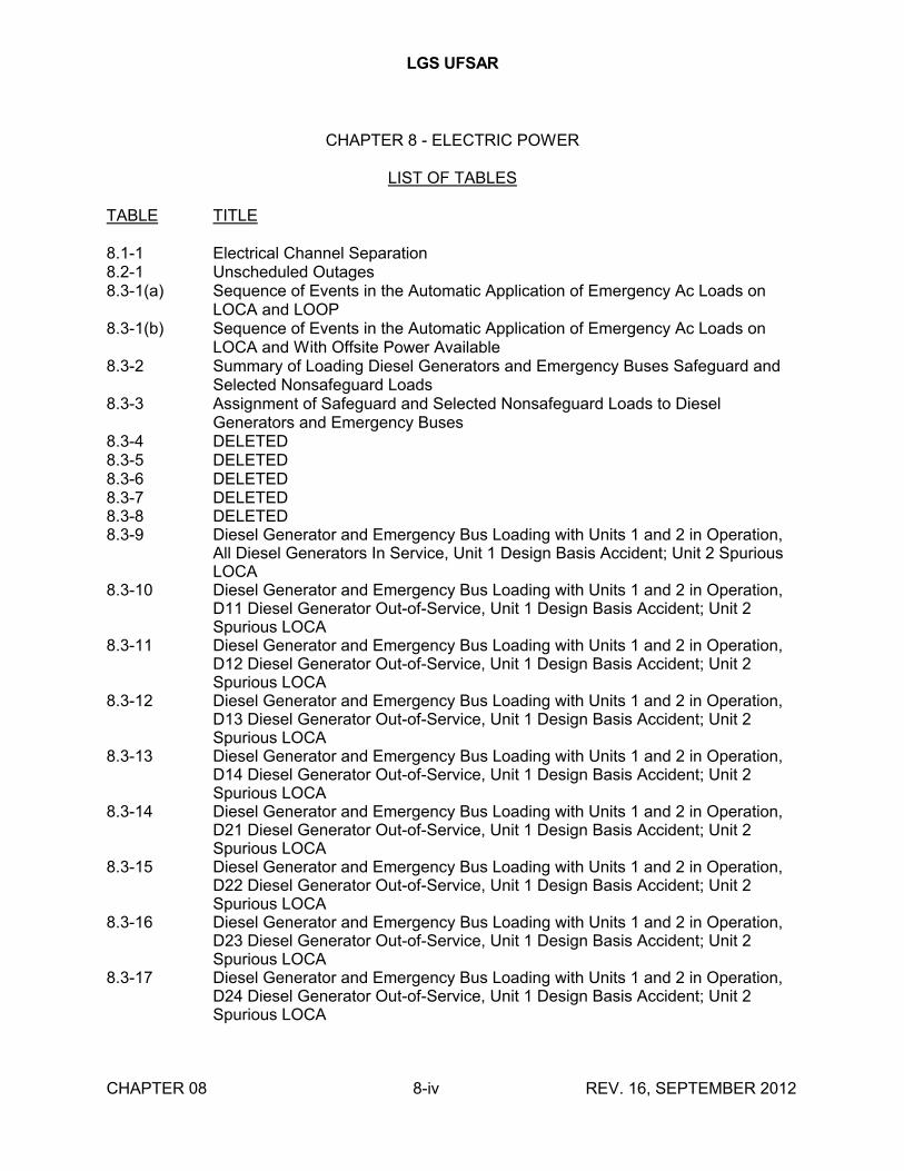
8.1-1 Electrical Channel Separation8.2-1 Unscheduled Outages8.3-1(a) Sequence of Events in the Automatic Application of Emergency Ac Loads on
LOCA and LOOP8.3-1(b) Sequence of Events in the Automatic Application of Emergency Ac Loads on
LOCA and With Offsite Power Available8.3-2 Summary of Loading Diesel Generators and Emergency Buses Safeguard and
Selected Nonsafeguard Loads8.3-3 Assignment of Safeguard and Selected Nonsafeguard Loads to Diesel
Generators and Emergency Buses8.3-4 DELETED8.3-5 DELETED8.3-6 DELETED8.3-7 DELETED8.3-8 DELETED8.3-9 Diesel Generator and Emergency Bus Loading with Units 1 and 2 in Operation,
All Diesel Generators In Service, Unit 1 Design Basis Accident; Unit 2 Spurious LOCA
8.3-10 Diesel Generator and Emergency Bus Loading with Units 1 and 2 in Operation, D11 Diesel Generator Out-of-Service, Unit 1 Design Basis Accident; Unit 2 Spurious LOCA
8.3-11 Diesel Generator and Emergency Bus Loading with Units 1 and 2 in Operation, D12 Diesel Generator Out-of-Service, Unit 1 Design Basis Accident; Unit 2 Spurious LOCA
8.3-12 Diesel Generator and Emergency Bus Loading with Units 1 and 2 in Operation, D13 Diesel Generator Out-of-Service, Unit 1 Design Basis Accident; Unit 2 Spurious LOCA
8.3-13 Diesel Generator and Emergency Bus Loading with Units 1 and 2 in Operation, D14 Diesel Generator Out-of-Service, Unit 1 Design Basis Accident; Unit 2 Spurious LOCA
8.3-14 Diesel Generator and Emergency Bus Loading with Units 1 and 2 in Operation, D21 Diesel Generator Out-of-Service, Unit 1 Design Basis Accident; Unit 2 Spurious LOCA
8.3-15 Diesel Generator and Emergency Bus Loading with Units 1 and 2 in Operation, D22 Diesel Generator Out-of-Service, Unit 1 Design Basis Accident; Unit 2 Spurious LOCA
8.3-16 Diesel Generator and Emergency Bus Loading with Units 1 and 2 in Operation, D23 Diesel Generator Out-of-Service, Unit 1 Design Basis Accident; Unit 2 Spurious LOCA
8.3-17 Diesel Generator and Emergency Bus Loading with Units 1 and 2 in Operation, D24 Diesel Generator Out-of-Service, Unit 1 Design Basis Accident; Unit 2 Spurious LOCA

LGS UFSAR
LIST OF TABLES (cont'd)
TABLE TITLE
CHAPTER 08 8-v REV. 16, SEPTEMBER 2012
8.3-18 Deleted8.3-18A Deleted8.3-19 Deleted8.3-20 Deleted8.3-21 Deleted8.3-22 Deleted8.3-23 Deleted8.3-24 Deleted8.3-25 Deleted8.3-26 Deleted8.3-27 Instrument and Control Systems Power Supply Panels8.3-28 Undervoltage Alarms8.3-29 Panel Alarms With Loss of Power as Possible Indirect Cause8.3-30 Instruments Used to Achieve Cold Shutdown8.3-31 DELETED8.3-32 This Table has been relocated to the TRM

LGS UFSAR
CHAPTER 08 8-vi REV. 16, SEPTEMBER 2012
CHAPTER 8 - ELECTRIC POWER
LIST OF FIGURES
FIGURE TITLE
8.1-1 Deleted
8.1-2 440 Volt System
8.1-3 208 V and Lower Voltage System
8.1-4 Medium Voltage System
8.1-5 120 Volt System
8.2-1 Transmission System and Startup Feeds
8.2-2 Transmission System Single Line
8.2-3 Third Offsite Source Emergency Backup
8.2-4 Transmission System Relay Single Line Diagram
8.2-5 Transmission System Arrangement of Cable Trenches
8.2-6 Transmission System Line Routings
8.3-1 Deleted
8.3-2 Deleted
8.3-3 Deleted

LGS UFSAR
CHAPTER 08 8.1-1 REV. 18, SEPTEMBER 2016
CHAPTER 8 - ELECTRIC POWER
8.1 INTRODUCTION
8.1.1 GENERAL
The electric power systems of the LGS Units 1 and 2 are designed to generate and transmit electric power into the PJM power network.
The two independent offsite electric power source connections to LGS are designed to provide reliable power sources for plant auxiliary loads and the engineered safeguard loads of both units. An alternate independent, but currently not connected, 13 kV offsite source, available as a potential source, can be connected to supply the engineered safeguard loads of both units in the event of the loss of one of the connected offsite power sources.
The onsite ac electric power system consists of Class 1E and non-Class 1E power systems. The two offsite power systems provide the preferred ac electric power to all Class 1E loads. One source is the 220-13 kV startup transformer in the 220 kV substation. The second source is from a 13 kV tertiary winding of the 220-500 kV bus tie autotransformer in the 500 kV substation. In the event of total LOOP sources, eight onsite independent diesel generators (four diesel generators per unit) provide the standby power for all engineered safeguard loads.
The non-Class 1E ac loads are normally supplied through the unit auxiliary transformer from the main generator. However, during plant startup, shutdown, and postshutdown, power is supplied from the offsite power sources through the 220-13 kV startup transformer and the 220-500 kV bus tie autotransformer.
Onsite Class 1E and non-Class 1E dc systems supply all dc power requirements of the plant.
8.1.2 UTILITY POWER GRID AND OFFSITE POWER SYSTEMS
The Unit 1 and 2 generators are connected by a separate isophase bus to their respective main step-up transformer banks as shown in Drawing E-1. The Unit 1 main step-up transformer bank, with three single-phase power transformers, steps up the 22 kV generator voltage to 242 kV; the Unit 2 bank, with three single-phase power transformers, steps up the 22 kV generator voltage to 500 kV. The 220 kV and 500 kV substations each use a breaker and one-half scheme arranged in an interior main bus hop-over design. Each substation has three elements initially and is arranged for future expansion to four or more elements. Element refers to each bus-to-bus connection and includes the associated disconnect switches, potential transformers, protective relaying, and control systems. The substations are approximately 2150 feet apart and are interconnected by a 500-220 kV bus tie transformer and transmission line. The 500 kV substation feeds two substations on the PECO Energy system, Whitpain and PBAPS North, which are part of the Keystone 500 kV grid. Both the 500 kV and 220 kV substations and the associated transmissions are tied into the PJM Interconnection.
The 13 kV alternate offsite source to LGS is made available from the Limerick 66-13 kV substation. The substation receives bulk power from the Moser and Cromby Stations.

LGS UFSAR
CHAPTER 08 8.1-2 REV. 18, SEPTEMBER 2016
Plant startup power, which is the preferred power for the engineered safeguard systems, is provided from two independent offsite power sources. The power for the engineered safeguard systems can also be provided from the alternate offsite source. The three sources are as follows:
a. 220-13 kV transformer connected to the 220 kV substation
b. A 13 kV tertiary winding on the 500-220 kV bus tie autotransformer
c. 66-13 kV transformer connected to the 66 kV Cromby-Moser tie line
The Perkiomen pumping station receives power from two 33 kV transmission circuits to supply power to the makeup water pumps and their auxiliaries.
The offsite power systems and their interconnections are described in detail in Section 8.2.
8.1.3 ONSITE POWER SYSTEMS
The onsite power system for each unit is divided into two major categories:
a. Class 1E Power System
The Class 1E power system supplies all Class 1E loads and other loads that are needed for safe and orderly shutdown and maintaining the plant in a safe shutdown condition.
The Class 1E power system for each unit consists of four independent channels, A, B, C, and D, which provide power to four divisions of Class 1E loads. With the exception of the ESW system, the RHRSW system, the SGTS, CSCWS and the control room and control structure ventilation systems, which are common systems, any combination of three-out-of-four divisions of Class 1E loads in each unit meets the design basis requirements. Common loads for the ESW and the RHRSW systems are split between the Unit 1 and Unit 2 Class 1E power supplies. Common redundant loads for the SGTS, CSCWS and the control room and control structure ventilation systems are fed from Unit 1 Class 1E power supplies.
Any combination of three-out-of-four divisions (EDGs) is acceptable for a single failure. However, for ECCS requirements (as stated in paragraph 6.3.1.1.2), an EDG operable configuration of 2 out of 4 is also acceptable.
Load division separation is shown in Tables 7.1-4, 7.1-5 and 7.1-6. Electrical channel separation is shown in Table 8.1-1. Physical separation is discussed in Section 8.1.6.1.14.
The Class 1E power system is shown on drawings E-15, E-16, E-28, E-29, E-33, and E-34.
A detailed description of the onsite ac and dc power systems is found in Sections 8.3.1 and 8.3.2, respectively.
b. Non-Class 1E Power System

LGS UFSAR
CHAPTER 08 8.1-3 REV. 18, SEPTEMBER 2016
The non-Class 1E onsite power system supplies electric power to nonsafety-related plant auxiliary loads. The non-Class 1E auxiliary system distributes power at 13.2 kV, 2.3 kV, 440 V, and 208/120 V voltage levels. These distribution levels are grouped into two symmetrical bus systems emanating from the 13.2 kV level as shown in drawing E-1.
Power transmitted to the utility grid is discussed in Section 8.2.
A detailed description of the onsite ac and dc power systems is found in Sections 8.3.1 and 8.3.2, respectively.
8.1.4 SAFETY-RELATED LOADS
The Class 1E loads supplied by the standby ac power system are listed in Table 8.3-3. Class 1E loads supplied by the Class 1E dc system are listed in Tables 8.3-19 through 8.3-26.
8.1.5 DESIGN BASES
The following design bases are applied to the design of the onsite and offsite power systems:
8.1.5.1 Offsite Power System
a. Electric power from the offsite power sources to the onsite distribution system is provided by two physically separated transmission lines designed and located to minimize the likelihood of simultaneous failure.
b. The loss of a generating unit, or the loss of the most critical unit on the power grid, does not result in total LOOP.
c. If there is the loss of one of the offsite power sources, a third separate power source can be connected within a 72 hour period to meet Regulatory Guide 1.93. This source has more than adequate capacity to provide power to the safeguard loads of both units.
8.1.5.2 Onsite Power System
a. One unit auxiliary transformer per generating unit is provided to supply power to the plant electrical auxiliary distribution system.
b. The two offsite sources common to both units are provided to supply offsite power to the safeguard power system. The offsite sources also supply power to their respective plant auxiliary ac loads during plant startup, shutdown, and postshutdown.
c. An alternate offsite power source is provided that can be connected if there is a loss of one of the offsite sources. This alternate offsite source can be connected within 72 hours.
d. A spare safeguard transformer is provided that can be connected if there is a failure of either safeguard transformer.

LGS UFSAR
CHAPTER 08 8.1-4 REV. 18, SEPTEMBER 2016
e. The onsite Class 1E electric power system is divided into four independent divisions per unit. With the exception of the power supply requirements for the ESW system, the RHRSW system, the SGTS, CSCWS and the control room and control structure ventilation systems, which are common systems, any combination of three-out-of-four divisions of Class 1E power in each unit can shut down the unit safely and maintain it in a safe shutdown condition. Common loads for the ESW and RHRSW systems are split between the Unit 1 and Unit 2 Class 1E power systems. Common redundant loads for the SGTS, CSCWS and the control room and control structure ventilation systems are fed from Unit 1 Class 1E power supplies.
Any combination of three-out-of-four divisions (EDGs) is acceptable for a single failure. However, for ECCS requirements (as stated in paragraph 6.3.1.1.2), an EDG operable configuration of 2 out of 4 is also acceptable.
f. Each unit has four independent dc Class 1E power systems corresponding to the four standby ac power system divisions and one independent dc non-Class 1E power system for the non-Class 1E dc loads.
g. Raceways are not shared by Class 1E and non-Class 1E cables, except where cables feed nonsafeguard equipment from Class 1E buses. Under these conditions, the non-Class 1E cables that are treated and identified as Class 1E are routed through one division of Class 1E raceways exclusively. Sharing of raceways in such cases is not considered to jeopardize the raceway separation, because the cables in such cases are isolated from the buses, by Class 1E isolation devices.
h. Special identification criteria as discussed in Section 8.1.6.1.14 are applied for Class 1E equipment, cabling, and raceways.
i. Separation criteria are established for preserving the independence of redundant Class 1E systems and providing isolation between Class 1E and non-Class 1E equipment.
j. The Class 1E electric systems are designed to satisfy the single failure criterion in accordance with IEEE 379.
k. Class 1E equipment and systems have been designed with the capability for periodic testing.
8.1.6 REGULATORY GUIDES AND IEEE STANDARDS
The design of the offsite power system complies with the requirements of GDC 5, GDC 17, and GDC 18 as discussed in Section 8.2.
Codes and standards applicable to the onsite power system are listed in Table 3.2-1. The design of the onsite power system complies with the requirements of GDC 2, GDC 4, GDC 5, GDC 17, GDC 18, and GDC 50 as discussed in Sections 8.3.1.2.1 and 8.3.2.2.1.
8.1.6.1 Conformance with Regulatory Guides

LGS UFSAR
CHAPTER 08 8.1-5 REV. 18, SEPTEMBER 2016
Conformance with applicable Regulatory Guides 1.6, 1.9, 1.22, 1.29, 1.30, 1.32, 1.40, 1.41, 1.47, 1.53, 1.62, 1.63, 1.73, 1.75, 1.81, 1.89, 1.93, 1.100, 1.106, 1.108, 1.118, 1.128, 1.129, and 1.131 is discussed below.
8.1.6.1.1 Regulatory Guide 1.6 (March 1971) - Independence Between Redundant Standby (Onsite) Power Sources and Between Their Distribution Systems (Safety Guide 6)
The design of the standby power system is in conformance with Regulatory Guide 1.6.
The standby power system consists of four independent divisions per unit. All safety-related loads are divided among the divisions so that loss of any one division does not prevent the minimum safety functions from being performed. Each division consists of both standby ac and dc power systems.
The ac loads of each division have connections to two independent offsite power supplies and to a single onsite diesel generator. The power feeder breakers to each division are interlocked so that only one of the power supplies can be connected at any one time, except during the diesel generator load test where the diesel generator is synchronized to one of the preferred offsite power sources. Only one diesel generator is tested at a time.
Each diesel generator is exclusively connected to the corresponding division. When operating from the standby sources, the diesel generator of one division cannot be paralleled, either manually or automatically, with the diesel generator of another division.
The dc power system of each unit consists of four division dc systems; two 125/250 V, 3-wire systems; and two 125 V, 2-wire systems. Each division is energized by its own batteries and chargers. The battery charger is supplied by its corresponding Class 1E ac power system. The dc power system of any one division is independent of any other dc power system.
8.1.6.1.2 Regulatory Guide 1.9 (March 1971) - Selection of Diesel Generator Set Capacity for Standby Power Supplies (Safety Guide 9)
The standby diesel generator capacities are in compliance with this edition of Regulatory Guide 1.9. Revisions 1 and 2 of the guide are not applicable to LGS as discussed in Section 1.8.
The continuous or the 2000 hour rating of the standby diesel generators is greater than the sum of conservatively estimated loads needed to be supplied following any design basis event. Load requirements are listed in Table 8.3-2.
The standby diesel generators are capable of starting and accelerating all engineered safeguard loads to the rated speed within the time and in the sequence shown in Table 8.3-1. They are capable of maintaining, during the steady-state and loading sequence, the frequency and voltage above a level that may degrade the performance of any of the loads below their minimum requirements. The standby diesel generators are capable of recovering from transients caused by step load increases or resulting from the disconnection of a partial or full load. Specifically, the standby diesel generators are designed to maintain frequency and voltage to not less than 95% and 75% of nominal, respectively, following a step load change. The frequency and voltage are restored to within 2% and 10% of nominal, respectively, within 60% of each load sequence time interval except for the time interval (3 seconds) between the RHR pump motor start and the load center breaker closure. However, during the preoperational tests, these loads started, accelerated,

LGS UFSAR
CHAPTER 08 8.1-6 REV. 18, SEPTEMBER 2016
and operated successfully. In addition, during the recovery from transients caused by step load increases or resulting from the disconnection of the largest single load, the speed of the diesel generator will not exceed 75% of the difference between the nominal speed and the overspeed trip setpoint or 115% of nominal, whichever is lower.
8.1.6.1.3 Regulatory Guide 1.22 (February 1972) - Periodic Testing of Protection System Actuation Functions (Safety Guide 22)
Refer to Section 7.1.2.5 for discussion of this guide.
8.1.6.1.4 Regulatory Guide 1.29 (February 1978) - Seismic Design Classification
The electrically related structures, systems, and components of this plant are in compliance with Regulatory Guide 1.29, except for paragraph C.1.m concerning the CRD manual control. Seismic design classification is discussed in Section 3.2.1.
8.1.6.1.5 Regulatory Guide 1.30 (August 1972) - Quality Assurance Requirements for the Installation, Inspection, and Testing of Instrumentation and Electric Equipment (Safety Guide 30)
The guidelines of ANSI N45.2.4 (1972) [IEEE 336 (1971)], as endorsed by this regulatory guide, have been met by the quality assurance program for the installation of safety-related items, although the standard is not specifically referenced in the constructor's quality assurance procedures. For QA during construction see the document "Limerick Generating Station Units 1 and 2; Summary Description of the Quality Assurance Program for Design and Construction," referenced in FSAR Section 17.1.
Conformance to the guide during plant operation is discussed in Section 17.2.
8.1.6.1.6 Regulatory Guide 1.32 (February 1977) - Criteria for Safety-Related Electric Power Systems for Nuclear Power Plants
All safety-related electric systems are in compliance with Regulatory Guide 1.32, except as it refers to Regulatory Guide 1.75, which is discussed in Section 8.1.6.1.14. The portions of Regulatory Guide 1.32 applying to offsite power and dc power are discussed in Sections 8.2 and 8.3.2, respectively.
IEEE 308 (1974), "IEEE Standard Criteria for Class 1E Power Systems for Nuclear Power Generating Stations" is generally accepted by Regulatory Guide 1.32.
Class 1E ac power systems are designed to ensure that any design basis event, as listed in table 1 of IEEE 308, does not cause either loss of electric power to more than one division, surveillance device, or protection system that could jeopardize the safety of the reactor unit; or transients in the power supplies, which could degrade the performance of any system.Controls and indicators for the Class 1E 4 kV bus supply breakers are provided in the control room and on the switchgear. Controls and indicators for the standby ac power supplies are also provided in the control room and on the local diesel generator control panels. Control and indication for the standby power system is described in Section 8.3.1.
LGS UFSAR
CHAPTER 08 8.1-7 REV. 18, SEPTEMBER 2016
Class 1E equipment is distinctly identified in the field and in associated design, operating, and maintenance documents. Physical identification is described in Section 8.3.1.3.
Class 1E equipment is qualified by analysis, by successful use under required conditions, or by actual testing to demonstrate its ability to perform its function under any applicable design basis events.
The surveillance requirements of IEEE 308 are followed in design, installation, and operation of Class 1E equipment and consist of:
a. Preoperational equipment tests and inspections are performed in accordance with the requirements described in Chapter 14, with all components installed. These tests and inspections demonstrate:
1. All components are correct and are properly mounted.
2. All connections are correct, and circuits are continuous.
3. All components are operational.
4. All metering and protective devices are properly calibrated and adjusted.
b. Preoperational system tests are performed in accordance with the requirements described in Chapter 14, with all components installed. These tests demonstrate that the equipment operates within design limits and that the system is operational and meets its performance specifications. These tests also demonstrate:
1. The Class 1E loads can operate on the preferred power supply.
2. The loss of the preferred power supply is detected.
3. The standby power supply is started and accepts design load in the sequence and time duration shown in Table 8.3-1.
4. The standby power supply is independent of the preferred power supply.
c. Periodic equipment tests are performed at scheduled intervals in accordance with the requirements of Chapter 16 to detect the deterioration of the equipment toward an unacceptable condition, to demonstrate that standby power equipment and other components that are not running during normal operation of the station are operable, and to demonstrate the operational readiness of the system.
The standby ac power supplies are not shared by the two units. The standby capacity of each unit is sufficient to operate the engineered safeguard loads following a DBA on that unit.
The two preferred offsite power supplies are shared by both units. The capacity of each offsite power supply is sufficient to operate the loads required for safe shutdown of both units with a LOCA in one unit and a simultaneous safe shutdown of the other unit.
Battery testing is described in Technical Specifications.

LGS UFSAR
CHAPTER 08 8.1-8 REV. 18, SEPTEMBER 2016
8.1.6.1.7 Regulatory Guide 1.40 (March 1973) - Qualification Tests of Continuous-Duty Motors Installed Inside the Containment of Water-Cooled Nuclear Power Plants
Limerick complies with the intent of Regulatory Guide 1.40. Refer to Section 3.11.4 for a discussion of qualification testing.
8.1.6.1.8 Regulatory Guide 1.41 (March 1973) - Preoperational Testing of Redundant Onsite Electric Power Systems to Verify Proper Load Group Assignments
The preoperational testing program is described in Chapter 14, and is in conformance with Regulatory Guide 1.41 except as may be modified by the general statement on regulatory guides in Section 14.2.
The onsite Class 1E electric power system, designed in accordance with Regulatory Guide 1.6 and Regulatory Guide 1.32, is tested as part of the preoperational testing program and also after major modifications. The tests are performed in accordance with the requirements outlined in Chapter 14. These tests verify the independence between the redundant onsite power sources and their loads.
The onsite Class 1E electric power system is tested functionally, one division at a time, by allowing one division to be powered only by its associated diesel generator while the bus is isolated from the preferred offsite power source. The offsite power source is isolated by direct actuation of undervoltage relays monitoring the safeguard system.
A safety injection signal is simulated to start the diesel generators and initiate automatic sequencing. Functional performance of the loads is checked. Each test is of sufficient duration to achieve stable operating conditions, thus permitting the onset and detection of adverse conditions that could result from improper assignment of loads.
Testing of each division is performed to indicate that no interconnection of the divisions exists. The buses and loads of the division under test are monitored to verify absence of voltage on these buses and loads while the remaining redundant divisions are energized.
8.1.6.1.9 Regulatory Guide 1.47 (May 1973) - Bypassed and Inoperable Status Indication for Nuclear Power Plant Safety Systems
The design of this plant is in compliance with Regulatory Guide 1.47, as follows:
a. An annunciator system is provided in the control room to automatically indicate, at the system level, the bypass or deliberately induced inoperability of the protection system, its auxiliary or supporting systems, and the systems actuated or controlled by the protection system.
b. Indication lights are used to indicate any bypass or inoperability status of components in the systems described in Item (a) above.
c. Manual capability to activate each system level annunciator is provided in the control room. Additional discussion is provided in Section 7.1.2.5.
LGS UFSAR
CHAPTER 08 8.1-9 REV. 18, SEPTEMBER 2016
8.1.6.1.10 Regulatory Guide 1.53 (June 1973) - Application of the Single Failure Criterion to Nuclear Power Plant Protection Systems
The design of the electric power systems complies with the position statements of this regulatory guide.
Consistent with the single failure criterion, only one failure is assumed to occur in the system following a design basis event. No single component failure results in the simultaneous loss of ac power to the four divisions. A single failure cannot propagate to another load division.
Cables and raceways of different channels are physically separated in accordance with the provisions of Regulatory Guide 1.75, as discussed in Section 8.1.6.1.14.
8.1.6.1.11 Regulatory Guide 1.62 (October 1973) - Manual Initiation of Protective Actions
The LGS design is in conformance with Regulatory Guide 1.62, as follows:
a. Manual initiation of each protective action is provided at the system level.
b. Manual initiation of a protective action at the system level performs all actions performed by automatic initiation.
c. The switches for manual initiation of protective actions at the system level are located in the control room.
Further details for controls and instrumentation are provided in Section 7.1.2.6.
8.1.6.1.12 Regulatory Guide 1.63 (October 1973 and July 1978) - Electric Penetration Assemblies in Containment Structures for Water-Cooled Nuclear Power Plants
The design of electric penetration assemblies is in compliance with Revision 0 (10/73) of Regulatory Guide 1.63, which endorses and amends IEEE 317 (1972), "IEEE Standard for Electric Penetration Assemblies in Containment Structures for Nuclear Power Generating Stations." Compliance with Revision 2 (7/78) of Regulatory Guide 1.63, which endorses IEEE 317 (1976), is also discussed in this section.
In accordance with Regulatory Guide 1.63, the electrical penetration assemblies are designed to withstand, without loss of mechanical integrity, the maximum fault condition versus time conditions that could occur as a result of a single random failure of circuit overload devices. The circuit breakers used for primary and backup protection are checked preoperationally and calibrated for time-overcurrent and instantaneous performance. These breakers, both Class 1E and non-Class 1E, will be checked periodically to ensure that their tripping characteristics have not changed. The fuses used for primary and backup protection are checked preoperationally for continuity and for proper model and size. The following system features are provided to ensure compliance with the regulatory guide:
a. Medium Voltage System
The only medium voltage loads in the primary containment are two variable-frequency reactor recirculating pump motors. Each recirculation pump motor is fed

LGS UFSAR
CHAPTER 08 8.1-10 REV. 18, SEPTEMBER 2016
by an ASD which is capable of providing up to 4 kV. The ASDs are located in the turbine enclosure.
To protect the penetration assemblies, two redundant Class 1E circuit breakers are used in series to provide the required primary and backup protection. Separate divisions of 125 V dc control power are used for the operation of these breakers. Tripping signals for these primary and backup breakers are independent, physically separated, and powered from separate sources.
The mechanical integrity of the penetration assemblies is maintained under the most severe fault condition, including the most severe fault condition.
b. 440 V System
In addition to the primary circuit breaker or primary circuit breaker with thermal overload relay, a backup breaker located in the same MCC cubicle is connected in each circuit to provide backup protection of the penetration assemblies. For all such Class 1E circuits, the primary and backup breaker overload and short-circuit protection systems are qualified for the environmental conditions. For all non-Class 1E circuits that penetrate into the containment, two breakers are connected in series to provide primary and backup protection. These non-Class 1E breakers are identical in design and construction to that of Class 1E breakers, thereby assuring high reliability.
Typical time-current characteristics of these protective devices indicate that the penetration assemblies can withstand the available fault current for the time duration required to trip either or both the primary and backup circuit breakers.
c. 208 V and Lower Voltage Systems
The low voltage control circuits powered from control power transformers are self-limiting in that the circuit resistance and/or short-circuit capability limits the fault current to a level that does not damage the penetration assemblies. The maximum initial fault current available from the control circuit transformers at the penetration assembly is as follows:
Maximum Initial Transformer Size Fault Current
120 VA 15.1 A200 VA 40.6 A
The minimum conductor size for control circuits powered from control power transformers through the electrical penetrations is #12 AWG. The maximum fault current values indicated above are initial fault current values. The final short circuit values are less than these values due to increased resistance of conductor and control power transformer at elevated temperature caused by the short circuit. A #12 AWG conductor can withstand 41A for a duration of 1000 hours. The final value of the short circuit current after taking increased resistance of cable and transformer is 35A. The smallest wire size used in control circuits is #14 AWG. PECo Test Report 48503 shows that a #14 AWG wire can carry 75 A continuously without insulation breakdown. Based on the above, it is concluded that both the

LGS UFSAR
CHAPTER 08 8.1-11 REV. 18, SEPTEMBER 2016
conductor through the penetration and the remainder of the control circuit can carry the maximum fault current developed by the control circuit transformers.
The remaining control and power circuits have a primary and backup fuse or breaker to ensure fault isolation. Typical time-current characteristics of these protective devices substantiate that the penetration assemblies can withstand the available fault current for the time duration required to trip either or both the primary and backup circuit breakers/fuses.
Field cables inside containment are connected to the containment penetration conductors in terminal boxes located next to the penetration. The method for connecting field cables to the penetration conductors is as follows:
1. Medium Voltage Power Penetration
The terminal lug on the field cable is bolted to the penetration connector assembly. The terminal lug and the connector assembly are then covered by heat shrink tubing. These are non-Class 1E terminations.
2. Low Voltage Power, Control and Instrumentation, Thermocouple and Low Level Signal
i. For penetration conductors that are 250 MCM, the terminal lugs on the penetration conductors and field cables are bolted and then covered by heat shrink tubing.
ii. For all other cases, the penetration conductors and field cable are spliced by in-line barrel splice connectors covered by heat shrink tubing.
3. Control Rod Drive Penetration
Field cables and penetration conductors are terminated by circular pin connectors. These are non-Class 1E terminations. The failure of the circular pin connectors will not degrade the containment pressure boundary integrity because the circular pin connectors do not form part of the pressure boundary.
4. Neutron Monitoring Penetration
i. Field coaxial cables to penetration coaxial conductors are connected by coaxial connectors covered by heat shrink tubing.
ii. Field coaxial cables to penetration #16 AWG conductors are spliced by in-line barrel splice connectors covered by heat shrink tubing.
All splices discussed in (2) and (4) are qualified to withstand a LOCA or steam line break accident. Supportive documentation that confirms the qualification of the splices is included in the LGS EQR.
d. Instrument Systems

LGS UFSAR
CHAPTER 08 8.1-12 REV. 18, SEPTEMBER 2016
The overload and short-circuit capability in the instrument systems are sufficiently low so that no damage can occur to the penetration assemblies.
Figures 8.1-2 through 8.1-5 provide time-current curves for penetrations in use at LGS. These curves include I2t penetration and cable rating curves for instantaneous, long and short time overcurrent trips provided by primary and backup protective devices. In addition these curves include circuit configuration.
The LGS purchase order for electrical penetrations was issued on January 15, 1974, which precedes the issuance of Revisions 1 (5/77) and 2 (7/78) of the guide and the issuance of IEEE 317 (1976) as endorsed by these revisions of the guide. Therefore, LGS did not use the latest revisions of the guide.
However, the LGS electrical penetrations are in conformance with Regulatory Guide 1.63 (Rev 2 -7/78), except as discussed and clarified by the following:
a. Rated Short-Circuit Current and Duration
The rated short-circuit current and duration for the electrical penetrations are based on maximum available fault currents, which were calculated using methods accepted by the industry, and on required breaker clearing time. The penetration manufacturer performed tests that were more severe than LGS service requirements. However, the latest revision of the guide requires that the short-circuit current must be based on the symmetrical current being initially fully offset by a dc component having a decrement based on specified x/r ratios. This was not specified for the LGS electrical penetrations and therefore not verified by the manufacturer.
b. Test Margins
The test parameters that were specified for qualification testing were conservative as compared to the maximum possible service conditions. In addition, the manufacturer exceeded these parameters in the conservative direction during qualification testing. Test margins according to IEEE 317 (1976) were not specified for the LGS penetrations.
c. Materials Flammability
All nonmetallic materials are required to be classified by testing as "nonburning" or "self-extinguishing" as defined by IEEE 317. An adhesive used on the interior of some types of shrink tubing used in the penetrations is flammable. It is noted that the use of this adhesive in a splice as used by Conax has been qualified by test to the flame test requirements of IEEE 383 (1974). The adhesive used in a splice is protected by the shrink tubing and, except for a small portion that oozes from the ends of the splice, is not exposed to air or open flames. The latent heat content of the exposed adhesive is much less than in an ordinary wooden match. The small amount that is present and its slow-burning characteristic mean that it could not be a significant source of flame or fire damage. This adhesive is a small amount of combustible material surrounded by a relatively large amount of noncombustible and self-extinguishing material. Therefore, it does not constitute a hazard.

LGS UFSAR
CHAPTER 08 8.1-13 REV. 18, SEPTEMBER 2016
d. Thermal Aging
To demonstrate that the assembly will survive an accident condition the prototype assembly was qualified by accelerated thermal aging equivalent to a 40 year plant life in the normal service environment, in accordance with IEEE 317 (1972). IEEE 317 (1976) and Regulatory Guide 1.63 require accelerated thermal aging tests in accordance with IEEE 98 and IEEE 101, at a minimum aging time of 5000 hours.
e. Type Tests
LGS penetration assembly prototype tests conform to IEEE 317 (1972). IEEE 317 (1976) as amended by the guide contains the following requirements, which were not considered for LGS penetration assembly prototype tests:
1. Specified sequence of required tests
2. Impulse withstand test on medium voltage power conductors
3. Partial discharge (corona) test
4. Cycling and aging test as related to shipping, storage, welding, and thermal cycling
5. Seismic tests in accordance with IEEE 344 (1975)
8.1.6.1.13 Regulatory Guide 1.73 (January 1974) - Qualification Tests of Electric Valve Operators Installed Inside the Containment of Nuclear Power Plants
Selection of electric valve operators for use inside the containment is in compliance with Regulatory Guide 1.73.
The electric valve operators for service inside the containment are tested in accordance with IEEE 382 (1972), as modified by Regulatory Guide 1.73. The tests consist of aging, seismic, and accident or other special environmental requirements. Test parameters are discussed in Section 3.11.2.
8.1.6.1.14 Regulatory Guide 1.75 (September 1978) - Physical Independence of Electric Systems
The requirements of Regulatory Guide 1.75 are met, except as discussed and clarified below. The regulatory guide endorses the IEEE 384 (1974), "IEEE Trial Use Standard Criteria for Separation of Class 1E Equipment and Circuits," subject to the additions and clarifications delineated in section C of the guide.
a. General Separation Criteria
1. Required Separation
Electrical equipment and wiring for the engineered safeguard system and the RPS are segregated into separated channels/divisions as shown in
LGS UFSAR
CHAPTER 08 8.1-14 REV. 18, SEPTEMBER 2016
Tables 7.1-4, 7.1-5, 7.1-6 and 8.1-1, so that no single credible event is capable of disabling sufficient equipment to prevent reactor shutdown, removal of decay heat from the core, or isolation of the primary containment if there is an accident. The engineered safeguard system and RPS are separated from each other, and each is further separated into four channels/divisions. Separation requirements apply to control and instrument power and motive power for all systems concerned. The degree of separation required varies with the potential hazards in a particular area.
Arrangement and/or protective barriers ensure that no locally generated force or missile can destroy redundant portions of the engineered safeguard system and/or RPS.
The arrangement of wiring is designed to eliminate, insofar as is practicable, all potential for fire damage to cables and to separate the engineered safeguard or RPS channels/divisions so that fire in one division does not propagate to another division.
Equipment and circuits requiring separation are identified on documents and drawings in a distinctive manner.
2. Methods of Separation
The separation of circuits and equipment is achieved by separate safety class structures, distance, or barriers, or combination thereof.
The following isolation devices are used at LGS to provide isolation between Class 1E and non-Class 1E circuits:
(a) 4 kV circuit breakers
(b) 480 V circuit breakers
(c) 480 V motor starters
(d) Auxiliary relays
(e) Optic isolators
(f) Control switches
(g) Voltage transducers
(h) Electronic isolation amplifiers
(i) Electronic, magnetically coupled signal isolators
(j) Electronic, magnetically coupled signal converters

LGS UFSAR
CHAPTER 08 8.1-15 REV. 18, SEPTEMBER 2016
The circuit breakers and motor starters are qualified to perform an isolation function through prototype tests performed to NEMA and ANSI standards. In addition, the devices are qualified for seismic and environmental conditions in accordance with NUREG-0588 as discussed in Sections 3.10 and 3.11.
The auxiliary relays used as isolation devices are listed in section I.C. of Reference 8.1-1. The devices were tested for both overvoltage and overcurrent isolation. The test results are given in section 5.4 of the test report.
Optic isolators are seismically and environmentally qualified. The fiber optic cable inherently isolates the Class 1E input from the non-Class 1E system at the receiving end of the cable.
Isolation via qualified electronic magnetically coupled signal isolators and converters is achieved in various system applications such as RCIC. The magnetic coupling of component's input and output signals provides a high degree of passive isolation of damaging fault conditions.
Control switches are seismically qualified and located in a mild environment. The manufacturer's test data on breakdown voltages and current interrupting capacity of the contacts are used to determine the adequacy of the device for isolation purposes.
The voltage transducers are seismically qualified and located in a mild environment. They have been tested and accepted as isolation devices.
3. Compatibility with Mechanical Systems
The separation of Class 1E circuits and equipment ensures that the required independence is not compromised by the failure of mechanical systems served by the Class 1E systems. For example, Class 1E circuits are routed and/or protected so that the failure of related mechanical equipment of one redundant system cannot disable Class 1E circuits or equipment essential to the operation of the other redundant system(s).
4. Associated Circuits
Associated circuits are not uniquely identified as such. These circuits are treated and identified as Class 1E up to an isolation device and are isolated on a LOCA signal, with the following clarifications and exceptions:
(a) When relays and other devices are used as isolation devices between Class 1E and non- Class 1E circuits, the 6 inch separation
requirement at the device terminals is not maintained in accordance with IEEE 384 (1974), section 4.6.1. The basis for not providing 6 inches of separation at the device terminals is based on test results given in section 5.4 of the above mentioned test report, which shows
LGS UFSAR
CHAPTER 08 8.1-16 REV. 18, SEPTEMBER 2016
that no separation is required between wires terminating on isolation relays.
(b) All feeders to non-Class 1E 4 kV motor loads and to all non-Class 1E 440 V MCCs that are fed from Class 1E buses are treated and identified as Class 1E even beyond the isolation device. However, these loads are tripped in the event of a LOCA in the unit they are associated with and are routed in dedicated Class 1E raceways. They do not become associated with any other Class 1E division. The non-Class 1E motor loads that are fed from the Class 1E buses are in full compliance with IEEE 384 (1974), section 4.5.(2). The isolation device is the Class 1E 4 kV circuit breaker. The cable schemes associated with these breakers are Class 1E and are routed as such. Where these cables enter equipment, they are treated as non-Class 1E for separation purposes. These cables are isolated on an accident signal; therefore, they may be treated as non-Class 1E in accordance with IEEE 384 (1981).
(c) The public address and fire alarm panel that feeds non-Class 1E loads is fed from a Class 1E bus. This panel is not tripped on LOCA, because intentional disconnection of the fire alarm system is a violation of the National Fire Code and is considered unacceptable for plant safety. The distribution transformer and panel are qualified and seismically supported to Class 1E criteria. All circuits originating from this panel are run in conduits that contain only PA or fire alarm system wiring. All circuits originating from this panel are protected by thermal magnetic circuit breakers in the panel. In addition, the 440 V feed to the transformer is protected by a molded-case circuit breaker in the motor control center. Each of these circuit breakers is qualified and purchased as Class 1E; therefore, two Class 1E isolation devices exist between the non-Class 1E public address and fire alarm circuits and the Class 1E 440 V bus.
(d) Several non-Class 1E drywell cooler fan motors located inside the drywell are fed from a Class 1E bus, and the cabling is routed as Class 1E. The non-Class 1E RPS/UPS inverters are fed from a Class 1E dc bus, and the cabling is routed non-Class 1E. Two Class 1E circuit breakers are provided for redundant overcurrent protection on each of these circuits. These breakers provide isolation between the non-Class 1E load and the Class 1E bus and will be periodically tested. The non-Class 1E RCIC barometric condenser vacuum pump, RCIC vacuum tank condensate pump, HPCI vacuum tank condensate pump, and HPCI gland seal condenser vacuum are fed from a Class 1E bus, and the cabling is routed as Class 1E. Two class 1E fuses are provided on both the positive and negative feeds for redundant overcurrent protection. These loads are not automatically isolated on a LOCA signal.

LGS UFSAR
CHAPTER 08 8.1-17 REV. 18, SEPTEMBER 2016
(e) In several cases, redundant Class 1E overcurrent devices (e.g., fuses or breakers) are provided in series for isolation between Class 1E power sources and non-Class 1E instrumentation and controls.
5. Non-Class 1E Circuits
Non-Class 1E circuits are separated from Class 1E circuits by the separation requirements specified in Section 8.1.6.1.14.b. Non-Class 1E 440 V loads that are fed from Class 1E MCCs use a shunt trip device on the MCC breaker or a trip logic in the combination starter controls to isolate the circuit on a LOCA signal from the unit from which they are powered. These circuits are treated as non-Class 1E from the MCC to the load and control devices or they are routed as Class 1E only in the division with which they are associated.
6. Class 1E Circuits
Class 1E circuits are separated from Class 1E circuits of a different channel/division as described in items a.1, a.2, and a.3 above, except as discussed and clarified below.
The RCIC steam supply line inboard containment isolation valve is provided with a manually actuated power transfer switch which allows manual transfer from the valve's normal Division 3 source to an emergency Division 1 source. Physical independence is not maintained when the manual transfer switch is actuated to the emergency position because the valve's power and control cables, which are identified and routed as Division 3, are powered from Division 1 in this situation. The manual transfer switch enables this valve to be powered and controlled from a Division 1 emergency source in order to permit the valve to be opened in the event of a fire that requires the RCIC system for safe shutdown but which has caused the valve to spuriously close with subsequent loss of Division 3 ac power.
The manual transfer switch consists primarily of two molded-case circuit breakers with an interconnecting mechanical linkage that allows closure of only one breaker at a time. Qualification of the manual transfer switch ensures that the switch is capable of performing its safety function and/or remaining in a safe mode under all conditions postulated to occur during its installed life. Locking closed the door of the terminal box in which the manual transfer switch is located, locking open the Division 1 feeder breaker, and maintaining the keys to these locks under administrative control assures that control of the manual transfer switch and the Division 1 feeder breaker is limited to, aside from testing, operator discretion only in the event of a fire with concurrent loss of Division 3 ac power.
In addition, plant procedures require that:
(a) The valve be controlled from the remote shutdown panel with the remote shutdown panel transfer switch in the emergency position

LGS UFSAR
CHAPTER 08 8.1-18 REV. 18, SEPTEMBER 2016
when using Division 1 power. This limits the interconnection of Division 3 circuits with Division 1 power to the MCC, the remote shutdown panel and interconnecting wiring. Control complex wiring and circuits will not be involved.
(b) Division 3 power shall always be removed from the manual transfer switch (by opening one of the two circuit breakers in Division 3) before Division 1 power is connected and Division 1 power shall always be removed from the manual transfer switch (by opening one of the two circuit breakers in Division 1) before Division 3 is reconnected. This limits the number of power divisions connected to the manual transfer switch at any time to one.
Annunciation and indication of the manual transfer switch in the emergency position meets the requirements of Regulatory Guide 1.47. Testing of the manual transfer switch is limited to operating conditions 4 and 5 as defined by the Technical Specifications. Limiting the testing of the manual transfer switch to those operating conditions when the reactor is at low pressure provides adequate assurance that any potential consequence which might arise due to these Division 3 power and control cables becoming energized from a Division 1 source could not affect the operability of the minimum number of operable ac power sources specified by the Technical Specifications for these operating conditions.
b. Specific Separation Criteria
1. Cables and Raceways
The minimum separation distances for raceways are given in paragraphs 4 and 5 below. The following general criteria apply to all cable installations: (a) Cable splices in raceways are prohibited. Cable splices are only
made in manholes, boxes or suitable fittings. Splices in cables passing through the containment penetration assemblies are made in terminal boxes located next to the assemblies.
(b) Cables and raceways are flame retardant.
(c) The design basis is that the cable trays are not filled above the side rails. Tray fill for control cable trays and instrumentation cable trays is 50% maximum, i.e., the cross-sectional area of the cable in the tray will not exceed 50% of the available cross-sectional area of the tray, and 40% maximum for cable trays containing power cables. If tray fill exceeds the above stated maximum fill, tray fill is justified and documented.
(d) Some RPS cables are routed in ESF raceway. These cables are identified as RPS and routed in steel flexible conduit in accordance with GE design requirements. This installation is acceptable because flexible conduit provides the required system fail-safe

LGS UFSAR
CHAPTER 08 8.1-19 REV. 18, SEPTEMBER 2016
protection and because none of the RPS cables are redundant to the ESF cables located in the same raceway.
2. Identification of Non-PGCC Cables and Raceways
Exposed Class 1E raceways are identified in a distinct and permanent manner at intervals not to exceed 15 feet. In addition, these raceways are also identified where they pass through walls and/or floors. Class 1E raceways are identified before the installation of their cables.
Cables installed in cable trays are identified at intervals not exceeding 5 feet, to facilitate initial verification that the installation conforms to the separation criteria. These cable identifications are applied before or during their installation.
Class 1E cables are identified by a permanent marker at each end in accordance with the design drawings or cable schedule.
Color coding is used to meet the above requirements and to distinguish between Class 1E systems and between Class 1E and non-Class 1E systems. The coding precludes the need to consult any reference material to distinguish between redundant Class 1E and between Class 1E and non-Class 1E systems.
Panel internal wiring is marked with its connection diagram identity at each point of termination.
3. Identification of PGCC Cables and Raceways
Cables run in the floor sections are color banded every ten feet. The longitudinal floor ducts of the power generation control complex are marked with color coded raceway markers on the top of the steel side beam. The cables contained in each duct are generally of one division only. A cable of one division may be run in the duct of another division only if it is run in flexible steel conduit. Because of the congestion of these ducts, only the top several cables are visible when the floor cover is removed.
The purpose of the requirement of IEEE 384 to color code cables every five feet is to aid in the installation of these cables to ensure that they are pulled into the correct raceway. Cable installation has been performed to approved quality control procedures and in accordance with the system cable routing document provided by GE.
Based on the above, we believe that no increase in plant safety would be achieved by marking the cables in the power generation control complex floor every five feet and that the present ten foot interval meets the intent of IEEE 384.
4. Cable Spreading Room/Control Complex
LGS UFSAR
CHAPTER 08 8.1-20 REV. 18, SEPTEMBER 2016
The control complex consists of control room, cable spreading room, and auxiliary equipment room. The auxiliary equipment room mainly consists of relay panels and terminal cabinets integrated with module-type floor sections, with lateral and longitudinal ducts that are used as raceways and barriers. This module-type assembly, which is the PGCC, is covered separately in paragraph 6.
The control complex does not contain high energy equipment (such as switchgear and transformers) or potential sources of missiles or pipe whip and is not used for storing flammable materials.
Circuits in the cable spreading room and control room are limited to control functions, instrument functions, and those power supply circuits and facilities serving the control room. Power supply feeders to distribution panels are installed in enclosed raceways that qualify as barriers. The circuits passing through the cable spreading room are limited to 120/208 V ac and 250 V dc, except for lighting feeder circuits in the cable spreading area. The lighting feeder circuits are 277 V ac, but are routed in conduits used explicitly for lighting.
The minimum separation distance between the redundant Class 1E cable trays is 1 foot horizontally and 3 feet vertically. Where a 1 foot horizontal separation is not possible, lesser separation is justified by test and analysis or one of the following barrier arrangements is used: a flame retardant barrier is placed between the redundant cable trays and extends 1 foot above the trays or to the ceiling; or cables are installed in totally enclosed raceways up to a point where the minimum horizontal separation justified by test and analysis is met. Where cable trays of redundant channel/divisions must be stacked one above the other with less than 3 feet vertical spacing, lesser separation is justified by test and analysis or one of the following barrier arrangements is used: a flame retardant barrier is placed between the trays and extended to 6 inches beyond each side of the tray system or to the wall; or the cables are installed in totally enclosed raceways to a point where the minimum vertical separation justified by test and analysis is met. Where a crossover of one tray over another carrying a redundant channel/division is made, and minimum vertical separation distance (as determined by test and analysis) cannot be maintained, either fire barriers are installed between the trays extending a minimum of 1 foot beyond the crossing tray or cables are installed in enclosed raceway extending a minimum of one foot beyond the intersection. Separation requirements between Class 1E and non-Class 1E circuits are the same as for separation of redundant channel/divisions except where justified by test and analysis.
In general, a minimum separation of 1 inch is maintained between redundant enclosed raceways and between Class 1E and non-Class 1E enclosed raceways except in those cases where lesser separation is justified by test and analysis.

LGS UFSAR
CHAPTER 08 8.1-21 REV. 18, SEPTEMBER 2016
The separation provided between a totally enclosed raceway and a cable tray is the same as that provided between redundant cable trays except where lesser separation is justified by test and analysis.
The minimum separation required between redundant Class 1E dropout cables or between Class 1E and non-Class 1E dropout cables is one foot horizontal and 3 feet vertical except in those cases where lesser separation has been justified by test and analysis. Dropout cables are defined as any cable length not routed within a raceway. In cases where the minimum separation criteria justified by test and analysis cannot be met, dropout cables are wrapped with a fiberglass sleeving to the point where the minimum separation criteria is achieved.
The test results and analysis contained in Wyle Laboratories Test Report 46960-3 are the basis for the lesser raceway and dropout cable separation referenced in paragraphs 4 and 5. The separation criteria derived from this analysis are contained in LGS drawing 8031-E-1406, section 2.0.
5. General Plant Areas
In plant areas where potential hazards such as missiles and pipe whip are excluded, the separation distance between redundant Class 1E cable trays is 3 feet between trays separated horizontally, if no physical barrier exists between trays. If a horizontal separation of less than 3 feet exists, alternate methods as stated in paragraph 4 above are required. Vertical stacking of trays is avoided wherever possible; however, where cable trays of redundant channel/divisions are stacked, a vertical separation distance of 5 feet is required, or alternate methods as stated in paragraph 4 above are required. Where a crossover of one tray over another carrying a redundant channel/division is made, and the minimum vertical separation distance as determined by test and analysis cannot be maintained, either fire barriers are installed between the trays extending a minimum of 3 feet beyond the crossing tray or cables are installed in enclosed raceway extending a minimum of 3 feet beyond the intersection.
Separation requirements between Class 1E and non-Class 1E circuits are the same as for separation of redundant channel/divisions except where justified by test and analysis.
The separation requirements between totally enclosed raceways and between a totally enclosed raceway and a cable tray are the same as stated in paragraph 4 above.
The minimum separation required between redundant Class 1E dropout cables or between Class 1E and non-Class 1E dropout cables is 3 feet horizontal and 5 feet vertical except in those cases where lesser separation has been justified by test and analysis. In cases where the minimum separation criteria justified by test and analysis cannot be met, dropout cables are wrapped with a fiberglass sleeving to the point where the minimum separation criteria are achieved.

LGS UFSAR
CHAPTER 08 8.1-22 REV. 18, SEPTEMBER 2016
NMS cables located in the subpile room under the RPV are exceptions to these separation criteria. These cables are separated and routed in flexible conduit in this room wherever possible, but they may touch wherever necessary due to spatial limitation. Cables of different NMS divisions in this room are not bundled together where they are not in flexible conduit. Bundling of stainless steel jacketed LPRM cables is permitted.
6. Power Generation Control Complex
Detailed design basis, description, and safety evaluation aspects for the PGCC system are documented and presented in Reference 8.1-2. The separation criteria used for the internal panel wiring of the PGCC are given in Section 8.1.6.1.14.b.9.
Series-connected redundant protective devices are not required to clear faults internal to flexible conduit or to prevent overheating of adjacent cables. All flexible conduits in the power generation control complex are positively grounded to panel steel and were checked to ensure that the resistance to ground on the conduit is less than 4 ohms at all points. The probability of the failure of a single fuse to clear a fault was given in WASH-1400, appendix III, table III.2-1, as 3x10⁻⁵ to 3x10⁻⁶, which shows that this scenario is an extremely low probability event. In addition, the test results presented in section 5.3.2 of the above mentioned test report show that the damage of adjacent essential cables due to an uncleared internal conduit fault is not a credible event. For this reason, it is not necessary to install redundant overcurrent devices in circuits that run in flexible conduit.
7. Power Supply
(a) Standby Diesel Generators
Standby diesel generators are housed in separate compartments within a seismic Category I structure. The auxiliaries and local controls of each unit are housed in the same compartment as the unit they serve.
(b) Dc System
Redundant Class 1E batteries and their associated chargers are located in separate compartments within a seismic Category I structure. Each battery room is exhausted by an individual ventilation duct to a common exhaust plenum. Two redundant Class 1E axial flow exhaust fans service the common exhaust duct-work.
Also, the battery chargers of redundant load groups are physically separated in accordance with the requirements of Regulatory Guide 1.75.

LGS UFSAR
CHAPTER 08 8.1-23 REV. 18, SEPTEMBER 2016
(c) Ac Distribution System
All redundant Class 1E switchgear, MCCs, and distribution panels are physically separated in accordance with Regulatory Guide 1.75.
8. Penetrations
Redundant Class 1E containment electrical penetrations are dispersed around the circumference of the containment and are physically separated in accordance with the requirements of section 5.5 of IEEE 384 (1974). In general, non-Class 1E and RPS circuits are not routed in penetrations containing Class 1E circuits. Where Class 1E, RPS and non-Class 1E circuits are routed in the same penetration, separation is maintained by routing the cables in flex conduit or fiberglass sleeving up to the penetration feedthrough. Class 1E, RPS and non-Class 1E wiring are not routed through common feedthroughs. The feedthrough steel casing forms the separation barrier between Class 1E feedthrough of different divisions and between Class 1E and non-Class 1E feedthroughs and between ESF and RPS feedthroughs. Two divisions of Class 1E RTD wiring are also routed through the suppression pool penetration in this manner to maintain separation.
9. Control Room and Auxiliary Equipment Room Panels
The main control panels are located in a control room within a seismic Category I structure. The control room is protected from, and does not contain, high energy equipment such as switchgear, transformers, rotating equipment, or potential sources of missiles or pipe whip.
No single control panel includes wiring essential to the protective function of two systems that are redundant to each other, except as allowed by the following:
(a) Floor-to-panel fireproof barriers are provided between adjacent panels of different channels/ divisions.
(b) Penetration of separation barriers within a subdivided panel is permitted, provided that such penetrations are sealed or otherwise treated so that an electrical fire could not reasonably be expected to propagate from one section to the other and destroy the protective function.
(c) When locating manual control switches of redundant divisions on separate panels is considered prohibitively (or unduly) restrictive to manual operation of equipment, the switches are located on the same panel, provided that no credible single event in the panel can disable both sets of redundant manual or automatic controls.
The design basis for the internal panel separation criteria is presented in section 2.1 of the WASH-1400 test report. The basis of

LGS UFSAR
CHAPTER 08 8.1-24 REV. 18, SEPTEMBER 2016
that test report is reflected in the description of the separation requirements for Class 1E components mounted in control panels (Item (5) below). The test program showed that the revised separation criteria are adequate for protection against the consequences of a sustained overcurrent condition on one of the circuits in the panel. The criteria are not designed to protect against an exposure fire in the panel because alternate safe shutdown methods are provided in accordance with 10CFR50, Appendix R, in the event of a fire in the control room.
Wherever wiring of two divisions exists in a single panel section, separation is maintained as follows:
(1) A minimum of 6 inches spatial separation is maintained between Class 1E wiring of different divisions. IEEE 384 (1981), section 6.6.2, states that Class 1E cables and wires internal to control panels are to be separated by 6 inches, or a barrier shall be installed between redundant Class 1E wiring. The same separation is maintained between Class 1E and non-Class 1E wiring. Redundant Class 1E cables entering the control panel enclosure also meet these requirements.
External to the panel, the raceways meet the separation requirements of IEEE 384 for nonhazard areas. Where the cables pass through blockouts into the panels, they are separated by fire barriers.
(2) A minimum of 6 inches spatial separation is maintained between Class 1E and non-Class 1E wiring.
(3) Where the above spatial separation cannot be maintained, one or a combination of the following shall be provided:
One of the divisions of wiring is enclosed in flexible steel conduit to the point where the above separation is achieved.
Hygrade Thermoflex 1200 fiberglass sleeving is installed on control and instrumentation wiring to the point where the above separation is achieved.
One inch spatial separation is maintained between Class 1E and non-Class 1E wiring where the non-Class 1E wiring is secured with stainless steel cable ties, and between redundant Class 1E wiring where both the divisions of wiring are secured with stainless steel cable ties.

LGS UFSAR
CHAPTER 08 8.1-25 REV. 18, SEPTEMBER 2016
(4) The following exceptions to the above separation criteria are allowed:
Relays Used as Isolation Devices:
Non-Class 1E wires terminating on contacts of isolation relays are not separated from other wires in the same panel, regardless of safety status or division. They are not bundled with Class 1E wires.
Redundant Class 1E wires terminating on a common isolation relay are not separated from each other at the relay terminals. They are routed away from the relay to achieve the required separation within aminimum distance.
Where Class 1E wiring is located above #10 AWG or smaller non-Class 1E wiring, one inch separation will be provided.
Thermocouple wires of different divisions of the steam leak detection system do not require separation from any other thermocouple wires in panels C609, C611, C620, and C640. These thermocouple wires are separated from power and control cables using the separation criteria above. Bases for this exception are as follows:
i) All thermocouple wires are #16 AWG, whichwill not ignite due to overcurrent.
ii) All thermocouple cables for this system are routed in instrumentation trays that do not contain power or control cables; therefore, no potential overcurrent source exists for these wires.
In certain cases, less than one inch separation is allowed between redundant enclosed raceways. The rationale for this exception is discussed in section 5.3.2 of Reference 8.1-1.
(5) Class 1E components of different divisions, but which are not redundant, installed on a common panel are separated by one inch or a flame retardant barrier. Non-Class 1E components are separated by one inch or a flame retardant barrier from Class 1E components. Class 1E components that serve redundant systems are separated by 6 inches or aflame retardant barrier, e.g., core spray A from core spray B. The fire-resistant materials that are used as barriers for internal panel separation are panel steel, solid or flexible
LGS UFSAR
CHAPTER 08 8.1-26 REV. 18, SEPTEMBER 2016
steel conduit and fiberglass sleeving. Where a barrier is required between devices in a common panel, the metal casing of the device is considered to be an adequate barrier for containing internal device failures. The analyses that shows that a failure of one circuit will not affect an adjacent circuit are provided in Reference 8.1-1.
Exceptions to these component separation criteria are allowed in cases where it has been shown that a sustained overcurrent through the device will not cause the ignition of that device. Indicating lamps, isolation relays, panel meters, and terminal blocks are specific examples of this exception.
(d) Panel internal Class 1E wiring is not color coded. Wires are marked with their respective connection diagram identity at each point of termination. The connection diagram denotes the separation division for each cable.
10. Instrument Racks and Panels:
Redundant Class 1E instruments and instrument racks are separated so that any design basis event will not cause the failure of more than one division of instrumentation needed to mitigate the effects of that event.
Physical separation of redundant circuits and devices is provided within each instrument panel as discussed in paragraph 9 above.
11. Sensors and sensor-to-process connections:
Redundant Class 1E sensors and their connections to the process system have been sufficiently separated so that the functional capability of the protection system is maintained despite any single design basis event or result therefrom, including the secondary effects of design basis events, such as pipe whip, steam release, radiation, missiles, or flooding.
Where practicable, redundant Class 1E sensors and process connecting lines are brought out at widely divergent points, using large components, such as pressure vessels or pipes, as protective barriers. Where necessary, additional barriers are provided to protect against damage from a credible common cause.
12. MSIV and Turbine Stop Valve Terminal Boxes
In the MSIV and turbine stop valve terminal boxes, separation is not maintained within these boxes as any postulated failure in the box will not prevent the RPS from performing its intended safety function. Bases for this exception are provided below.
In each MSIV terminal box, two divisions of wiring are present, i.e., RPS ac (nonsafety-related) and one Class 1E dc division. Given a failure in the terminal box, three types of failures can be assumed:

LGS UFSAR
CHAPTER 08 8.1-27 REV. 18, SEPTEMBER 2016
i) Open circuit
ii) Hot short
iii) Short to ground
For the first scenario, the MSIVs would fail closed because the pilot solenoids would be de-energized. For the second scenario, while it could be postulated that the pilot solenoids would stay energized, the redundant MSIVs would not be affected because the outboard MSIV pilot solenoids are fed from different ac and dc buses than are the inboard MSIVs. For the third scenario, refer to item iii) below.
Any failure within these terminal boxes would not degrade the safety-related dc system because:
i) Given any failure, only one division of the four safety-related dc divisions would be involved.
ii) There is a 5 A fuse in both dc feed legs in the logic panel feeding the dc solenoids. There is also a 30 A fuse in each leg at the dc distribution panel. Because these two fuses are in series between the terminal box and the dc distribution bus, the probability of both fuses failing to clear a hot short is conservatively estimated to be 9x10⁻¹⁰ based on failure information given in WASH-1400, appendix III, table III.2-1. This is considered to be acceptable.
iii) A short of the dc feed to ground would not unacceptably degrade the dc system because each dc system is ungrounded. The ground would be detected by a Class 1E ground detector and the dc system would continue to operated as designed.
Other exceptions to the above criteria may be allowed. These exceptions will be analyzed to consider the magnitude and duration of a credible high impedance faulted condition and will be documented.
13. CAC Inboard Nitrogen Purge Isolation Valves
The control circuits for the two primary containment nitrogen purge inboard PCIVs, one valve for the drywell (HV-057-*21) and the other for the suppression chamber air space (HV-057-*31), are supplied from the same electrical division. A single failure is prevented by electrical interlocks between the valves, which utilize contacts in the position switches on the two valves. A normally open contact in the position switch of both valves is wired in series with the other valve control circuit. This arrangement prevents both valves from being open at the same time. The cables between the interlocks and the valves are run in separate conduits.
If one of the position switch contacts failed open, the interlocked valve would be prevented from being opened. If one of the contacts failed closed, the interlocked valve could be opened, however, the first valve would then go

LGS UFSAR
CHAPTER 08 8.1-28 REV. 18, SEPTEMBER 2016
closed due to the interlock. Hot shorts between contacts on the position switches are not considered, since contacts on a switch have been evaluated to provide acceptable divisional separation. Shorts between cables are not credible since they are routed in separate conduits.
With the interlocks in place, electrical systems separation criteria (ref. UFSAR Section 7.1.2.2.3.2.2) and the single-failure criterion (IEEE 379, 1972 or 1979) are met.
8.1.6.1.15 Regulatory Guide 1.81 (January 1975) - Shared Emergency and Shutdown Electric System for Multi-Unit Nuclear Power Plants
The design of the standby electric power systems is in conformance with Regulatory Guide 1.81.
The dc power systems are not shared between the units.
Each unit is provided with separate and independent onsite ac and dc electric systems.
8.1.6.1.16 Regulatory Guide 1.89 (November 1974) - Qualification of Class 1E Equipment for Nuclear Power Plants
Regulatory Guide 1.89, Revision 0, does not apply to LGS. LGS electrical equipment requiring qualification was qualified in accordance with NUREG-0588, Category II as described in Sections 3.11 and the LGS EQR. Replacement components for electrical equipment requiring qualification that were installed after February 1985 are qualified to the requirements of 10CFR50.49 unless there are sound reasons to the contrary, as defined in Regulatory Guide 1.89 Rev. 1.
8.1.6.1.17 Regulatory Guide 1.93 (December 1974) - Availability of Electric Power Sources
LGS complies with this regulatory guide as discussed in the Technical Specifications.
8.1.6.1.18 Regulatory Guide 1.100 (August 1977) - Seismic Qualification of Electric Equipment for Nuclear Power Plants
This guide is not applicable to LGS per its implementation section.
Regulatory Guide 1.100 endorses and modifies IEEE 344 (1975), "Seismic Qualification of Class 1E Power and Protection Systems." LGS Class 1E equipment is in full compliance with IEEE 344 (1971) for components purchased before issuance of IEEE 344 (1975). All electrical equipment purchased later is qualified to IEEE 344 (1975). Seismic qualification of electrical equipment is discussed in Section 3.10.
8.1.6.1.19 Regulatory Guide 1.106 (March 1977) - Thermal Overload Protection for Electric Motors on Motor- Operated Valves
This guide is not applicable to LGS per its implementation section, nevertheless, the thermal overload design for motors on MOVs is in conformance with Regulatory Guide 1.106, except for Item b below.
Either thermal overload protection devices are not used, have permanent electrical jumpers installed, or are bypassed during an accident condition. The overload bypass philosophy on MOVs with overloads that do not have permanent jumpers is incorporated as follows:
a. MOVs with spring return-to-center control switches.

LGS UFSAR
CHAPTER 08 8.1-29 REV. 18, SEPTEMBER 2016
These MOVs can be initiated manually or automatically.
1. Manual initiation
During manual operation, the thermal overload is normally in the trip circuit; however, the thermal overload can be bypassed by holding the control switch in the appropriate OPEN or CLOSE position. The associated OUT OF SERVICE annunciator will alarm, along with a white indicating light on the system's vertical board indicating a valve motor overload or loss of power condition. By checking the valve indicating lights, the operator can determine whether the alarm is due to loss of voltage or motor overload.
2. Automatic initiation
The thermal overload is bypassed in automatic operation of the Class 1E MOVs in which the same annunciation sequence occurs as described in Item 1 above.
b. MOVs with maintained contact control switches:
1. Valves not required to operate automatically during an accident.The thermal overloads do not interrupt the MOV power circuit, but they alarm on an overload condition in the control room. The operator has the option to allow the valve to continue to operate or to interrupt power to the MOV by placing the control switch in the STOP position.
2. Valves required to operate automatically during an accident.
(a) Whenever the MOV operates, the thermal overloads do not interrupt the MOV power circuit, but they alarm on an overload condition in the control room.
8.1.6.1.20 Regulatory Guide 1.108 (August 1977) - Periodic Testing of Diesel Generator Units Used as Onsite Electric Power Systems at Nuclear Power Plants
The periodic testing of the diesel generator units will be in conformance with the requirements of Regulatory Guide 1.108 and IEEE 387 (1977) as follows:
a. The preoperational testing will be performed in accordance with the site test outlined in section 6.4 of IEEE 387 (1977).
b. A starting test as described in section 6.6.1 of IEEE 387 (1977) will be performed on each diesel generator at least once per month.
c. Periodic testing in accordance with section 6.6.2 of IEEE 387 (1977). Test frequency is determined by Technical Specifications.
In accordance with Station Blackout requirements, an emergency diesel generator reliability program which meets the requirements of USNRC Regulatory Guide 1.155 “Station Blackout” is in place.

LGS UFSAR
CHAPTER 08 8.1-30 REV. 18, SEPTEMBER 2016
8.1.6.1.21 Regulatory Guide 1.118 (June 1978) - Periodic Testing of Electric Power and Protection Systems
The LGS design provides the necessary capability for periodic testing of electric power systems in conformance with Section 5 of IEEE 338 (1977) as endorsed and amended by the guide.
Periodic testing capability of instrumentation and controls systems is discussed in Section 7.1.2.5.
Periodic testing of the Class 1E systems will be in accordance with Regulatory Guide 1.118 and IEEE 338 (1977).
8.1.6.1.22 Regulatory Guide 1.128 (October 1978) - Installation Design and Installation of Large Lead Storage Batteries for Nuclear Power Plants
This guide does not apply to LGS per its implementation section. Regulatory Guide 1.128 endorses and amends IEEE 484 (1975), "IEEE Recommended Practice for Installation Design and Installation of Large Lead Storage Batteries for Generating Stations and Substations." The installation design and installation of the Class 1E batteries for LGS are in conformance with IEEE 484 (1975).
8.1.6.1.23 Regulatory Guide 1.129 (February 1978) - Maintenance, Testing, and Replacement of Large Lead Storage Batteries for Nuclear Power Plants
The maintenance and testing of the LGS batteries will be performed in accordance with IEEE 450 (1995).
An acceptance test of the battery capacity was performed at the factory prior to initial shipment. A service test, as described in IEEE 450-1980, Section 5.3, was performed on the Class 1E batteries on completion of the initial installation. Replacement batteries will receive an equivalent level of testing that envelopes both the acceptance and service tests. Thereafter, a service test, as described in IEEE 450 (1995), will be performed periodically in accordance with Regulatory Guide 1.129, except the test will be performed at least once per 24 months. Also, to determine the service life remaining in the battery, a performance test will be conducted at least once per 60 months. This test may be performed in lieu of the service test every second testing period (every four years).
IEEE 450-1995 is used for its recommendations regarding battery connection resistance as indicated in Annex D, Section D.2 of the standard, for specific gravity correction per Section 3.3.1.6 and 3.4.2 of the standard and for providing an alternative method to determine the state of charge of the battery per Section 4.5 of the standard.
8.1.6.1.24 Regulatory Guide 1.131 (August 1977) - Qualification Tests of Electric Cables, Field Splices, and Connections for Light-Water-Cooled Nuclear Power Plants
Regulatory Guide 1.131 endorses and modifies IEEE 383 (1974), "Type Test for Class 1E Electric Cables, Field Splices, and Connections for Nuclear Power Generating Stations." LGS Class 1E cables, splices, and connections except for the battery cart intercell/intercart jumpers and cart to battery jumpers are in full compliance with IEEE 383 (1974). Compensatory measures are taken to mitigate the consequences of cable ignition in the area(s) in which the Non-IEEE 383 battery
LGS UFSAR
CHAPTER 08 8.1-31 REV. 18, SEPTEMBER 2016
cart intercell/intercart cables and cart to battery cables are used. For further information on qualification testing refer to Section 3.11.
8.1.6.1.25 Regulatory Guide 1.155 (June 1988) - Station Blackout
LGS complies with Regulatory Guide 1.155 and was evaluated in accordance with the requirements using guidance from NUMARC 87-00, except where RG 1.155 takes precedence.
For LGS Units 1 and 2, the minimum required Station Blackout coping duration shall be four hours as determined by NUMARC 87-00 guidelines.
LGS has opted to use an alternate ac power (AAC) approach (excess diesel generator capacity) to cope with and recover from a station blackout. AAC power is available within one hour of the station blackout. For LGS Units 1 and 2, the AAC power source satisfies the requirements for station blackout.
For LGS Units 1 and 2, Emergency Diesel Generator target reliability levels are maintained at or above 0.95 per demand. An Emergency Diesel Generator reliability program is established to ensure that target reliability program is established to ensure that target levels are maintained.
Station Blackout is further described in Section 15.12.
8.1.6.2 Conformance with IEEE Standards
8.1.6.2.1 IEEE 387 (1972) - Criteria for Diesel Generator Units Applied as Standby Power Supplies for Nuclear Power Generating Stations
The design of the standby power supplies is in compliance with IEEE 387 (1972). The following paragraphs analyze compliance.
a. Adequate cooling and ventilation equipment is provided to maintain an acceptable service environment within the diesel generator compartments during and after any design basis event, even without support from the preferred power supply.
b. Each diesel generator is capable of starting, accelerating, and accepting load as described in Section 8.3.1. The diesel generator automatically initiates its cooling equipment within an acceptable time after starting.
c. Frequency and voltage limits and the basis of the continuous rating of the diesel generator are discussed in the compliance statement to Regulatory Guide 1.9 in Section 8.1.6.1.2.
d. Mechanical and electrical systems are designed so that a single failure affects the operation of only a single diesel generator.
e. Design conditions such as vibration, torsional vibration, and overspeed are considered in accordance with the requirements of IEEE 387 (1972).
f. Each diesel governor can operate in either the isochronous or droop mode and the voltage regulator can operate in either the parallel or nonparallel mode. During
LGS UFSAR
CHAPTER 08 8.1-32 REV. 18, SEPTEMBER 2016
testing, the diesel generator is connected to and operated in parallel with the offsite power source. The electric governor is set in the droop mode whenever connected in parallel with a system in which another prime mover is controlling the frequency. Under automatic or emergency start conditions, the electric governing system and the voltage regulator are set automatically for isochronous and nonparallel mode, respectively.
g. Each diesel generator is provided with control systems permitting automatic and manual control. The automatic start signal is functional except when the diesel generator is in the maintenance mode. Provision is made for controlling the diesel generator from the control room and from the diesel generator room. Section 8.3.1 provides further description of the control systems.
h. Voltage, current, frequency, and output power metering is provided in the control room to permit assessment of the operating condition of each diesel generator.
i. Surveillance instrumentation is provided in accordance with IEEE 387 as follows:
1. Starting system - starting air pressure low alarm
2. Lubrication system - lube oil pressure low, lube oil temperature high, lube oil level low, and lube oil keep-warm failure alarms
3. Fuel system - fuel oil level in day tank high and low, fuel oil pressure low, fuel oil strainer differential pressure high, fuel oil filter differential pressure high, fuel oil level in storage tank high, and low alarm
4. Primary cooling system - ESW low pressure
5. Secondary cooling system - jacket water temperature high, jacket water keep-warm failure, jacket water pressure low, and jacket water expansion tank level low alarms
6. Combustion air systems - no alarm is provided, because the diesel generator duct-work does not contain any automatic dampers or features to cause failure in the combustion air supply
7. Exhaust system - pyrometers located at local gauge panel
8. Generator - generator differential overcurrent, ground neutral overcurrent, generator phase overcurrent, and antimotoring trip and alarm
9. Excitation system - generator loss of excitation and overexcitation alarm and field ground alarm
10. Voltage regulation system - generator overvoltage alarm
11. Governor system - engine overspeed trip

LGS UFSAR
CHAPTER 08 8.1-33 REV. 18, SEPTEMBER 2016
12. Auxiliary electric system - 480 V ac auxiliary power off, 125 V dc control power off, dc fuel pump power off alarms
A detailed list of trip and alarm functions and testing of the diesel generator is discussed in Section 8.3.1.1.3.
8.1.6.3 Conformance with Branch Technical Positions
Conformance with applicable BTPs ICSB 4, ICSB 8, ICSB 11, ICSB 18, ICSB 21, PSB 1 and PSB 2 is discussed below.
8.1.6.3.1 BTP - ICSB 4 (November 1975) - Requirements on Motor- Operated Valves In The ECCS Accumulator Lines
This BTP is not applicable to LGS because LGS is a BWR and therefore does not have safety injection tanks in the ECCS.
8.1.6.3.2 BTP - ICSB 8 - Use of Diesel Generator Sets for Peaking
LGS is in compliance with BTP ICSB 8. The diesel generator sets will not be used for peaking service. To preclude a potential for common failure modes, onsite and offsite sources are not interconnected except for short periods during testing when only one diesel at a time is tested.
8.1.6.3.3 BTP - ICSB 11 - Stability of Offsite Power Systems
A discussion of the grid stability analysis is given in Section 8.2.2.
8.1.6.3.4 BTP - ICSB 18 - Application of the Single Failure Criterion to Manually Controlled Electrically Operated Valves
LGS is in compliance with ICSB 18, except for the requirement for redundant position indication in the main control room.
Valves HV-13-109 and HV-13-110 (ESW supply and return to reactor recirculation pump seal and motor oil cooler valves) have been locked in the closed position. The power feeds to the motoroperators have been disconnected at the operator terminals and at the 480 V ac MCC compartments.
Remote position indication of these valves is not provided in the control room. Valve position is administratively controlled; the valves are locked in the required position and access to the keys is administratively controlled.
The position of these valves will be identified in a valve checkoff list. When verification of system operability is required, performance of the valve checkoff list in conjunction with the applicable lineup procedure is one method which may be used. When operability is verified in this manner, an independent verification of valve lineup will be accomplished by redundant performance of each valve checkoff list used. Use of a lineup procedure with its associated valve checkoff lists will not be the exclusive method available for verification of operability, but can be used in any circumstance. If valve positions are to be changed for surveillance or maintenance purposes, the procedure or other administrative control will have steps requiring return-to-normal valve lineup

LGS UFSAR
CHAPTER 08 8.1-34 REV. 18, SEPTEMBER 2016
prior to completion. The shift supervisor will not consider the system operable until all valves identified within the boundaries of the surveillance/maintenance activities have been returned to the position specified in the valve checkoff list. If valve positions are changed for operational purposes, these changes will be made in accordance with procedures having similar administrative controls.
8.1.6.3.5 BTP - ICSB 21 - Guidance for Application of Regulatory Guide 1.47
LGS is in compliance with BTP ICSB 21. Compliance with this position is discussed in Sections 8.1.6.1.9 and 7.1.2.5.11.
8.1.6.3.6 BTP - PSB 1 - Adequacy of Station Electric Distribution System Voltages
LGS is in compliance with BTP PSB 1.
BTP PSB 1 is met at LGS using the same degraded grid voltage monitoring system that was accepted by the NRC for PBAPS Units 2 and 3 (Reference 8.1-3). The following discussion responds to the numbered positions of BTP PSB 1.
a. On both offsite sources to each Class 1E bus, an ITE-27N definite time-delay relay with a 60 second timer monitors the offsite source voltage. This relay is set to drop out at 0.94 per unit voltage. Actuation of this relay after a 60 second time-delay will trip the associated 4 kV bus feeder breaker. Loss of voltage on the 4 kV bus actuates a GPI relay which initiates a diesel generator start and a transfer to the alternate source respectively. The purpose of the 60 second time-delay is to allow sufficient time for the automatic load tap changers on the 101 and 201 safeguard transformers to adjust and counter the degraded voltage condition.
An ITE-27 inverse-time relay with a timer is also installed on the source side of each offsite source to each Class 1E bus. This relay will be set at 0.875 per unit voltage with a total time-delay of 60 seconds or less. It performs the same function as the ITE-27N and provides inverse time-delay with degrading voltage for protection of Class 1E equipment between 0.875 and 0.70 per unit voltage.
The time-delays associated with the ITE-27N and ITE-27 relays are automatically bypassed 9 seconds after the ITE-27N relay initiates when a LOCA signal is present. This limits the exposure of Class 1E equipment to degraded voltage condition to 9 seconds after the undervoltage relay operates while preventing spurious trips of the offsite source breaker during voltage transients caused by motor starts.
An NGV relay with a 0.9 second timer is also installed on the source side of each offsite source to each Class 1E bus. The relay is set at 0.70 per unit voltage and will perform the same function as the above relays. This relay provides for the start of the diesel generator and the transfer of the bus on the total loss of the associated offsite source.
A GPI relay monitors the voltage on each Class 1E 4 kV bus. The relay functions with no appreciable time-delay when the voltage on the bus falls below 0.40 per unit. Actuation of this relay initiates load shedding and after a time-delay provides a permissive signal to start the diesel generator and allow the affected bus to transfer
LGS UFSAR
CHAPTER 08 8.1-35 REV. 18, SEPTEMBER 2016
to the alternate source. This relay also provides an automatic closure signal to the diesel generator breaker after further time-delay if the automatic transfer fails.
An NGV relay for Unit 1 and an ITE-59D relay for Unit 2 with a setpoint of approximately 0.95 per unit also monitor the bus voltage on the 4 kV Class 1E buses. Actuation of either one of these relays initiates load sequencing after the voltage is restored to the bus. It is sealed in by the GPI relay to allow the load sequencing to continue during motor starting transients.
The above voltage monitoring scheme does not provide coincident logic to preclude spurious trips to conform to BTP PSB 1. However, spurious action of one undervoltage relay will only start one diesel generator and then transfer the affected bus to the alternate power source. The actuation of a second undervoltage relay is necessary to transfer the bus to the diesel generator. If the ITE-27N should fail to operate, it is backed up by the ITE-27. Therefore, this scheme conforms to the intent of the requirements of BTP PSB 1.
For periodic testing of this scheme, the individual relays can be bypassed with a permanently installed test block. When the test block bypass is in effect, the condition is annunciated in the control room, thereby meeting the requirements of the BTP and Regulatory Guide 1.47.
b. The GPI relay discussed above provides the load shedding on the Class 1E 4 kV buses. It is not bypassed during load sequencing because its setpoint for dropout is low enough to preclude spurious tripping under all load sequences.
c. The analyses required by this section of BTP PSB 1 were performed and were used in selecting the settings of the relays discussed above.
d. The tests required by this section of BTP PSB 1 will be performed during the startup test program.
Preoperational Test P-100.1 and the Voltage Regulation Verification Test, which is required by BTP-PSB-1 measure various bus voltages as loads are applied. These tests verify that proper voltage regulation on the 13.2 kV and 4 kV buses is maintained.
8.1.6.3.7 BTP - PSB 2 - Criteria For Alarms and Indications Associated With Diesel Generator Unit Bypassed And Inoperable Status
LGS is in compliance with BTP PSB 2. Compliance with this position is discussed in Sections 8.1.6.1.19 and 7.1.2.5.11.
LGS UFSAR
CHAPTER 08 8.1-36 REV. 18, SEPTEMBER 2016
8.1.7 REFERENCES
8.1-1 PECo Research and Test Division Test Report 48503, "Design Verification Test Report, Internal Panel Control Wiring Separation Criteria, LGS Units 1 and 2," (September 1, 1982).
8.1-2 GE Topical Report, "Power Generation Control Complex" NEDO-10466 and amendments.
8.1-3 Letter to E.G. Bauer, Jr. (PECO) from J.F. Stoly (NRC) on Dockets 50-277 and 50-278, (February 18, 1982).
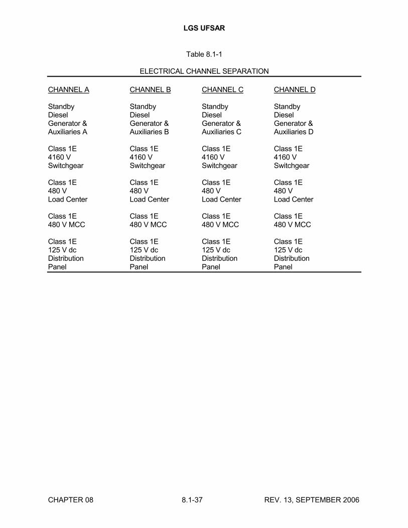
LGS UFSAR
CHAPTER 08 8.1-37 REV. 13, SEPTEMBER 2006
Table 8.1-1
ELECTRICAL CHANNEL SEPARATION
CHANNEL A CHANNEL B CHANNEL C CHANNEL D
Standby Standby Standby StandbyDiesel Diesel Diesel DieselGenerator & Generator & Generator & Generator &Auxiliaries A Auxiliaries B Auxiliaries C Auxiliaries D
Class 1E Class 1E Class 1E Class 1E4160 V 4160 V 4160 V 4160 VSwitchgear Switchgear Switchgear Switchgear
Class 1E Class 1E Class 1E Class 1E480 V 480 V 480 V 480 VLoad Center Load Center Load Center Load Center
Class 1E Class 1E Class 1E Class 1E480 V MCC 480 V MCC 480 V MCC 480 V MCC
Class 1E Class 1E Class 1E Class 1E125 V dc 125 V dc 125 V dc 125 V dcDistribution Distribution Distribution DistributionPanel Panel Panel Panel

LGS UFSAR
CHAPTER 08 8.2-1 REV. 18, SEPTEMBER 2016
8.2 OFFSITE POWER SYSTEM
8.2.1 DESCRIPTION
8.2.1.1 Offsite Power Sources
Offsite power is supplied from two independent, physically separated sources:
a. A 220-13 kV transformer No. 10 located at the LGS 220 kV substation
b. A 13 kV tertiary winding on the No. 4A and 4B 500-220 kV bus tie autotransformers through the No. 20 13-13 kV regulating transformer located in the LGS 500 kV substation
Physical and schematic representations of offsite and onsite transmission systems are shown in Figures 8.2-1, 8.2-2, and 8.2-6.
The LGS 220 kV substation supplies offsite power at 13.2 kV via the No. 10 220-13 kV transformer which has a nominal capacity of 61.6 MVA at 65C and a 15 kV underground cable run of 1000 feet outside the station. A transition to cable bus is made inside the turbine enclosure, where the cable bus continues for 330 feet to the station auxiliary bus 10A103. The underground installation protects the power supply from variable weather conditions such as high velocity winds, icing, and lightning.
The line primary protective relaying consists of three differential relays, which under fault conditions trip and lock out station auxiliary bus 10A103 breakers and breaker 105 in the 220 kV substation. Phase overcurrent and ground overcurrent relays provide backup relay protection. Breaker 105 is also tripped by No. 10 transformer protective relays and 220 kV bus No. 7 protective relays.
The 220 kV substation is supplied from three transmission sources:
a. 220-60 line which has a capacity(1) of 1200 MVA is routed on the east side of the Schuylkill River from the LGS 220 kV substation to a point opposite Cromby Station. From that point, the line leaves a railroad right-of-way, joins an existing PECO Energy right-of-way, and crosses the Schuylkill River to enter Cromby Station.
b. 220-61 line which has a capacity(1) of 1200 MVA is routed from the LGS 220 kV substation along the west side of the Schuylkill River on a railroad right-of-way to Cromby Station. The two 230 kV lines do not cross each other at any point.
c. The No. 4A and 4B bus tie autotransformers which interconnect the 220 kV and 500 kV substations and have a nominal capacity of 420 MVA each.
(1) Capacity values provided are nominal; utilized values are higher.

LGS UFSAR
CHAPTER 08 8.2-2 REV. 18, SEPTEMBER 2016
The LGS 500 kV substation supplies offsite power at 13.2 kV to station auxiliary bus 20A103 from the tertiary winding of one of the No. 4A or 4B bus tie autotransformers through the No. 20 13-13 kV regulating transformer. The tertiary winding has a nominal capacity of 95.7 MVA and the No. 20 transformer has a nominal capacity of 58 MVA. This substation is physically located 2150 feet from the LGS 220 kV substation, effectively minimizing the likelihood of their simultaneous failure under operating conditions, postulated accidents, and natural disasters. The 13.2 kV power is transmitted 2100 feet to the station via an underground cable run and 400 feet of cable installed in a tray beneath the site access railroad bridge that spans Possum Hollow Run ravine. A transition to cable bus is made inside the turbine enclosure, where the cable bus continues for a distance of 330 feet to station auxiliary bus 20A103. The underground installation avoids exposure to adverse weather conditions.
As shown in Figures 8.2-1 and 8.2-2, the two offsite power sources do not share any common structures, systems, or components external to the generating station. Internal to the generating station, the offsite sources terminate in a common room on separate and independent buses that are approximately 90 feet apart. The No. 4 bus tie autotransformer that provides load flow stability between the 220 kV and 500 kV substations represents a common link between the two offsite sources; however, at least one 13 kV and two 220 kV circuit breakers provide isolation between the two startup feeds as shown in Figure 8.2-2.
Pilot wire relaying is used for line primary protection that, under fault conditions, trips and locks out station auxiliary bus 20A103 breakers and breaker 205 in the 500 kV substation. Backup relay protection is provided by phase overcurrent and ground overcurrent relays. Breaker 205 is also tripped by No. 4 transformer protective relays, 500-220 kV bus tie protective relays, and No. 20 regulating transformer protective relays.
The 500 kV substation is supplied from four transmission sources:
a. 5010 line which has a capacity(2) of 2780 MVA crosses the Schuylkill River from the west and runs above both of the 230 kV transmission lines. It is terminated in the LGS 500 kV substation. Where the existing 5010 line leaves the 500 kV substation towards the east, it becomes the 5030 line.
b. 5030 line which has a capacity(2) of 2780 MVA.
c. 5031 line which has a capacity(2) of 2780 MVA parallels the 5030 line from the 500 kV substation to Whitpain for the operation of LGS Unit 2.
d. The No. 4A and 4B bus tie autotransformers.
From Figure 8.2-6, it can be seen that the requirements of GDC 17 are met in that in the unlikely event of the 5010 line falling and causing the failure of both 230 kV transmission lines, the 5030 line would still be available to provide an offsite source of power for the safe shutdown of the plant.
(2) Capacity values provided are nominal; utilized values are within 2% of nominal.

LGS UFSAR
CHAPTER 08 8.2-3 REV. 18, SEPTEMBER 2016
During unit operation, normal auxiliary power for the station is supplied from two 47 MVA unit auxiliary power transformers (one per unit) connected to the generator leads. Startup and Class 1E bus power is provided from the two independent offsite sources. Either offsite source can supply the 13.2 kV unit auxiliary buses and the 4 kV Class 1E buses for normal plant startup and shutdown and supply all normally connected loads including loads that may be automatically transferred to them when a LOCA in one unit coincides with a safe shutdown in the remaining unit. Each offsite source supplies an emergency auxiliary (safeguard) transformer with a nominal capacity of 14 MVA that steps down the 13.2 kV to 4.16 kV and connects through interlocked circuit breakers to every 4 kV Class 1E bus. Both offsite sources are available continuously to the Class 1E buses.
A spare 14 MVA 13.2/33-4.16 kV transformer is located onsite solely as a replacement for either the Unit 1 or Unit 2 13.2-4.16 kV safeguard transformer. The spare transformer has the same capacity as the safeguard transformers, which is more than adequate for safe shutdown of the plant. In the event of failure of either the Unit 1 or Unit 2 safeguard transformer, the faulty safeguard transformer will be removed and physically replaced by the spare.
The 6680, 66 kV transmission line serves as a potential, but currently not-connected alternate offsite source for use in the event of loss of one of the normal offsite sources. Line 6680 is tapped and provides power to the Limerick 66-13 kV substation. Aerial cable is installed between the 66-13 kV substation to a terminal pole located outside of the 220 kV substation where it converts to underground cable and is routed to the alternate offsite source breaker (No. 252-55401) installed north of the Unit 1 turbine building. In the event of loss of one of the normal offsite sources resulting in an outage time in excess of 72 hours, cables will be connected between breaker 252-55401 and the affected safeguard transformer. All work necessary to implement this alternate offsite source is expected to be accomplished within a 72 hour period to avoid a limiting condition of operation.
The capability to test the transfer of power from one offsite source to the other circuit can be accomplished from the control room (Drawing E-1). By tripping either the 101 or 201 transformer breaker, the loss of one offsite source will be simulated and the automatic transfer to the other offsite source will be initiated on the four Class 1E buses that are normally fed from that source. These buses can then be manually transferred back to their preferred source after the transformer breaker is closed.
The 66-13 kV substation has a capacity rating of 24 MVA which is sufficient to supply all connected and automatically transferred loads when a LOCA in one unit coincides with a safe shutdown in the remaining unit. The 6680 line terminates at Cromby Station and Moser Substation. Moser substation receives bulk power from the Cromby Station via two 66 kV transmission lines, is solidly tied into the 33 kV distribution system and has three combustion turbine generators.
8.2.1.2 Switchyards
Both the 220 kV and 500 kV substations use a breaker and one-half scheme. This arrangement is shown in Figures 8.2-1 and 8.2-2. Both substations have three bus elements initially, with provisions for future expansion to four bus elements. Element refers to each bus-to-bus connection. The 500 kV substation contains a manually or automatically switched 200 Mvar shunt capacitor bank which is part of the PJM system of 500 kV capacitors. Both substations employ primary and backup relay protection plus breaker failure protection schemes. The substations are interconnected by a 500-220 kV bus tie transformer and a 220 kV transmission line. The tie line is

LGS UFSAR
CHAPTER 08 8.2-4 REV. 18, SEPTEMBER 2016
approximately 100 feet from the Unit 1 generator line at the 220 kV substation and is approximately 200 feet from the Unit 2 generator line at the 500 kV substation. Both LGS substations ultimately interconnect with the PJM Interconnection through their respective transmission lines.
Each main generator is connected by an isolated phase bus to its respective step-up transformer bank. The Unit 1 maximum gross generator output of approximately 1240 MWe is fed to the 220 kV substation via three 22-242 kV, 525 MVA Unit 1 main transformers. The Unit 2 maximum gross generator output of approximately 1240 MWe feeds into the 500 kV substation via three 22-500 kV, 525 MVA Unit 2 main transformers. A system spare 22-220 kV 422 MVA transformer is installed next to the C phase Unit 1 transformer for immediate use should a fault occur on one of the three operating transformers. A system spare for the Unit 2 22-500 kV transformers is stored next to the Water Treatment Plant.
The relaying associated with the 220 kV and 500 kV substations and transmission lines is shown in Figure 8.2-4. Three separate protective relaying schemes are used on the 500 kV and 220 kV transmission lines. The first two schemes use primary and backup high speed relays with a power line carrier for directional comparison relaying logic. In the 500 kV substation, carrier relaying is on A phase and B phase of the transmission lines except for line 5031 which uses Fiber Synchronous Optical Network (SONET) for both primary and backup relaying. The 220 kV substation transmission line carrier relay protection is on A phase and C phase. The redundant relays operate from separate current transformers and separate secondary windings of the same potential device. Each substation has its own dc battery and battery charger. The charger is fed from an essential ac bus which has two alternate feeds with an automatic throw-over. Low dc voltage is alarmed in the substation control house and the LGS control room. Because this dc system and the substation protective relays are non-Class 1E, redundancy is not required. Direct current control circuits are fused separately for the redundant relay protection channels. Each line relaying initiates operation of separate redundant trip coils at the 500 kV circuit breakers and one trip coil at the 220 kV circuit breakers. The third scheme is breaker failure protection for a stuck breaker. This is provided by tripping adjacent breakers and transmitting signals to trip the circuit breaker at the remote line terminal. Separate carrier paths or channels are provided for each line relaying scheme.
The use of three relaying schemes with independently fused direct current feeds and independent 500 kV circuit breaker trip coils, along with current shorting switches and potential switches, permits inservice shutdown and test of any one relay and control scheme while maintaining two protective relaying schemes in service. The use of the breaker and one-half arrangement allows for the outage of one breaker without taking a line, transformer, or generator out-of-service. Testing equipment is installed for carrier line relaying to allow inservice functional testing of the directional comparison relaying logic. After initial calibration, the equipment is periodically inspected, and readings are recorded.
Each 500 kV and 220 kV bus element has two protective bus differential relaying schemes, either of which may be shut down for testing while maintaining the other in service for bus protection. All control operations, except actual tripping of the breakers, can be done while maintaining the bus in service.
The 220 kV and 500 kV breakers in both the substations are controlled from the substation control houses. These breakers are also controlled via a SCADA system from the SAMAC Control Center with the following exceptions: Unit 1 breakers 535 and 635, Unit 2 breakers 235 and 335 and

LGS UFSAR
CHAPTER 08 8.2-5 REV. 18, SEPTEMBER 2016
breakers 105 and 205. The above mentioned exceptions are controlled via independent hard-wired circuits from the LGS control room.
All circuit breakers have sufficient stored energy for at least one open-close-open operation after loss of power.
Figure 8.2-5 shows the cable trench arrangements in the 220 kV and 500 kV switchyards. All control power circuits to the switchyard equipment are routed in these trenches. Control circuits for the various pieces of equipment are separated into individual cables. Primary and backup relay and control circuits are separately fused and are separated into individual cables. All cables are direct-buried in the trenches.
Relay and circuit breaker functional trip tests on all of the offsite power sources are made periodically.
The substation control batteries are tested periodically as follows:
a. Weekly - Voltage and specific gravity of the pilot cell are recorded. Overall voltage of the battery is recorded.
b. Quarterly - Voltage is recorded for each cell, and specific gravity is recorded for at least 10% of cells. Overall battery voltage is recorded.
c. Yearly - Annual battery inspection in addition to the quarterly tests.
8.2.1.3 Control Room Monitoring of Offsite Power Systems
The status of the offsite power system is monitored in the control room. A dedicated supervisory system provides the following status indications along with other pertinent information:
a.(3) Transmission Line Current for:
220-60 Line 5030 Line220-61 Line 5031 Line5010 Line
b.(3) 220 kV Substation Bus Voltage
c.(3) 500 kV Substation Bus Voltage
d.(3) 220 kV Substation Breaker Positions
e. 500 kV Substation Breaker Currents
f.(3) 500 kV Substation Breaker Positions
g.(3) #4 Tie Transformer current
h.(3) #105 Startup Breaker Position

LGS UFSAR
CHAPTER 08 8.2-6 REV. 18, SEPTEMBER 2016
i.(3) #205 Startup Breaker Position
j. Miscellaneous 220 kV and 500 kV Substation Alarms
8.2.1.4 Conclusion
The offsite power system has been designed for maximum reliability. All three sources of offsite power, including transmission lines and transformers, have sufficient capacity to supply all connected loads including loads that may be automatically transferred to them when a LOCA in one unit coincides with a safe shutdown in the remaining unit. The design and configuration of the offsite power system with provisions for periodic testing are in full conformance with GDC 5, GDC 17 and GDC 18, and Regulatory Guide 1.32 (1977) and Regulatory Guide 1.93 (1974).
8.2.2 ANALYSIS
8.2.2.1 Transient Stability
Detailed transient stability studies were made for both LGS units using load flow (POWERFLO) and transient stability (TRANSTAB) computer simulation programs. These computer programs are widely recognized in the electric utility industry and are being used by over 140 domestic and foreign utilities, government agencies, and universities.
The stability evaluation consisted of analysis of prefault and postfault load flow simulations and of transient stability digital computer calculations. Examination of the 1985 peak and light load levels showed the light load level to be most critical for stability because of the higher impedance and lower system inertia seen by the LGS units. Thus, all results are based on 1985 light load conditions. For all load flow simulations and associated stability calculations, a detailed representation of the PECO Energy system and the other PJM Interconnection systems was modeled including a significant representation of the systems in the surrounding Interconnected Power Pools. Altogether 1208 buses, 2158 lines, and 180 individual generators were represented in the model. The LGS units and other PJM Interconnection generators were represented in the transient stability calculations by appropriate inertias and machine reactances, with generator excitation systems and turbine governors being modeled in great detail to accurately simulate generator transient performance. The generating units of companies outside the PJM Interconnection were represented by their transient reactances and inertias.
The results of the studies show that both LGS units are stable for the most severe type of fault (three-phase) at the most critical locations on the electric network system. Specifically, the LGS generating units are stable for the following conditions:
a. A three-phase fault on any single 500 kV or 230 kV LGS circuit that is cleared by primary protective equipment.
_____________________
(3) Upon loss of the Unit 1 Plant Monitoring System, these items are available from the PECO Energy load dispatcher via dedicated phone line.

LGS UFSAR
CHAPTER 08 8.2-7 REV. 18, SEPTEMBER 2016
b. A three-phase fault on any single 500 kV or 230 kV LGS circuit, where the most critical LGS circuit breaker fails to open and the fault is cleared at LGS by backup protective equipment.
c. A three-phase fault on the transformer connecting the LGS 500 kV and 230 kV buses that is cleared by primary protective equipment.
d. A three-phase fault on the transformer connecting the LGS 500 kV and 230 kV buses, where the most critical circuit breaker fails to open and the fault is cleared at LGS by backup protective equipment.
e. Simultaneous three-phase faults on both LGS to Whitpain 500 kV circuits that are cleared by primary protective equipment.
Load flow simulations and stability calculations were examined to evaluate the transient and post-transient system conditions after the most serious network faults and after the sudden tripping of either LGS unit. The analysis of circuit loadings and bus voltages showed no adverse system conditions either during periods of steady-state operation or during system oscillations caused by a fault and its subsequent clearing.
Additional transient stability analyses were also completed to address the following three events:
a. Loss of the largest generating station, i.e., loss of PBAPS Units 2 & 3
b. Loss of the largest load
c. Loss of the most critical right-of-way, i.e., a three-phase fault on the four transmission lines on the 130-30 right-of-way:
1. 130-30 line, 138 kV
2. 220-62 line, 230 kV
3. 5030 line, 500 kV
4. 5031 line, 500 kV
The transmission system remained stable for all three cases with either one or both LGS units in service. The loss of both PBAPS units was the worst case affecting system frequency. A minimum system frequency of 59.95 Hz occurred 0.35 seconds after the trips, and it ran out to 0.48 seconds. During this transient, the LGS units will experience a minimum frequency 59.89 Hz. This is well within the design capabilities of all LGS electrical equipment.
The effect of the 200 Mvar manually or automatically switched shunt capacitor on the 500 kV substation bus and on Limerick generator stability was analyzed. The analysis showed no detrimental affect on the generator's stability even with the voltage regulators out of service. The study indicated voltage is slightly improved with the capacitor in service.
Additional transient stability studies are performed as major system changes occur. Recent examples include, Power Rerate Projects, Turbine Retrofit Projects, 500 kV capacitor additions, etc. The transmission system is tested against the MAAC Reliability Principles and Standards:

LGS UFSAR
CHAPTER 08 8.2-8 REV. 18, SEPTEMBER 2016
Transmission Requirements. All single, double, double circuit/stuck breaker contingencies are run as part of these additional studies. These contingencies are tested at the peak, intermediate and light load levels, with and without the increase of Limerick 1 & 2 Unit outputs. All MAAC transmission lines, 230 kV and above are monitored for any voltage and thermal limit violations. Faults are initiated at the 500 kV and 230 kV buses in the Limerick area. The MAAC system was found to remain stable for all tested faults which are cleared by either the primary and/or backup protective equipment.
Note: The information presented above regarding the Transient Stability is historical and is based on the original design basis conditions and does not represent current methodology required for licensing basis. The above transient stability studies were preformed in compliance with Mid-Atlantic Area Council (MAAC) standards. MAAC was replaced withReliability First Corporation (RFC) as the regional reliability organization to monitor and enforce compliance with North American Electric Reliability Council (NERC) standards.
The Transient Stability study is performed by the Transient Planning Entity (PJM) periodically and per request basis for major system modifications. The Transmission Planning Entity normal stability testing enforces the NERC criteria including contingencies under NER standards:
TPL-001 – Category A (Transmission Planning Standard for System Performance Under Normal Conditions),
TPL-002 – Category B (Transmission Planning Standard for System Performance Following Loss of a Single Bulk Electric System Element), and
TPL-003 – Category C (Transmission Planning Standard for System Performance Following Loss of Two or More Bulk Electric System Elements).
In addition to the NERC standard criteria, the Transmission Planning Entity reviews and enforces additional criteria testing as required by Nuclear Plant Interface Requirement (NPIR) for planning analyses of the electric system.
To satisfy the requirements of 10 CFR 50 Appendix A General Design Criterion – Electrical power systems (GDC 17), the results of the grid stability study must show that loss of the largest single supply to the grid does not result in the complete loss of preferred power. The analysis should consider the loss, through a single event, of the largest capacity being supplied to the grid, removal of the largest load from the grid, or loss of the most critical transmission line. This could be the total output of the station, the largest station on the grid, or possibly several large stations if these use common transmission tower, transformer, or a breaker in a remote switchyard or substation.
The above licensing basis requirements are considered Category B contingencies for which the Transmission Planning Entity ensures that they will not cause grid instability.
8.2.2.2 Outages of Transmission Lines in the Vicinity of LGS
To demonstrate the reliability of the transmission lines associated with LGS unscheduled outages of existing transmission lines in the area were investigated. The lines included in the study are the PBAPS to Whitpain 500 kV line, the three Whitpain to Plymouth Meeting 230 kV lines, and the Whitpain to North Wales 230 kV line. These lines were chosen because they presently link the substations associated with the LGS project.
8.2.2.3 Unscheduled Outages

LGS UFSAR
CHAPTER 08 8.2-9 REV. 18, SEPTEMBER 2016
Historically, outages in this area have been caused by lightning strikes, flashovers, galloping conductors, airplanes, and equipment failures.
Of the 14 outages listed in Table 8.2-1, 9 lasted less than one hour, 4 lasted less than one day, and one lasted 5 days.

LGS UFSAR
CHAPTER 08 8.2-10 REV. 13, SEPTEMBER 2006
Table 8.2-1
UNSCHEDULED OUTAGES
Length Lines (mi) 1971 1972 1973 1974 1975 1976
PBAPS - Whitpain 72.4 0 0 1 0 1 5(1)
Plymouth Meeting - Whitpain 5.1 0 0 0 0 1 1
Plymouth Meeting - Whitpain 5.1 0 0 0 0 1 0
Plymouth Meeting - Whitpain 5.1 0 0 0 0 1 0
North Wales - Whitpain 3.5 0 0 1 0 0 2
____________________
(1) The PBAPS - Whitpain 500 kV line was interrupted four times on the same day in 1976 because of galloping conductors. Equipment has since been installed to prevent recurrence of the galloping conductors.

LGS UFSAR
CHAPTER 08 8.3-1 REV. 17, SEPTEMBER 2014
8.3 ONSITE POWER SYSTEMS
8.3.1 AC POWER SYSTEMS
8.3.1.1 Description
The onsite ac power systems are divided into Class 1E and non-Class 1E systems. Drawing E-1 shows a single-line diagram of both systems.
The onsite ac power systems consist of main generators, main step-up transformers, unit auxiliary transformers, safeguard transformers, and diesel generators, among other distribution system equipment. The onsite ac power distribution system has nominal bus voltage ratings of 13.8 kV, 4.16 kV, 2.4 kV, 480 V, and 208/120 V. Throughout this discussion and on all design drawings, the equipment utilization voltages are designated as 13.2 kV, 4 kV, 2.3 kV, 440 V, and 208/120 V.
8.3.1.1.1 Non-Class 1E Ac System
The non-Class 1E portion of the onsite power systems provides ac power for non-Class 1E loads. A limited number of non-Class 1E loads are important to the power generating equipment integrity and are fed from the Class 1E distribution system through the isolation devices.
The unit auxiliary transformer supplies all the non-Class 1E unit auxiliary loads. The unit auxiliary transformer primary is connected to the main generator isolated phase bus duct tap, while the secondary of the transformer is connected to the two 13.2 kV unit auxiliary buses through a nonsegregated phase bus.
During plant startup, shutdown, and postshutdown, power to the 13.2 kV buses is supplied from the offsite power sources, with one bus from each unit normally supplied through the 220-13kV startup transformer and one bus from each unit normally supplied through the 13 kV tertiary winding of either the No. 4A or 4B 500-220 kV bus tie autotransformer; the tertiary of the other autotransformer is available as a back-up source. In addition, during these conditions, manual or automatic fast transfer is provided to transfer the unit auxiliary buses to the startup power source to maintain continuity of power at the unit auxiliary distribution system. The interconnecting breakers are interlocked to prevent the connection of the startup power source and the unit auxiliary power source to the unit auxiliary buses at the same time.
In addition to the loading conditions mentioned in the above paragraph, the 13.2 kV startup buses also supply the power to the Class 1E loads through their respective 13.2 - 4.16 kV safeguard transformers, as discussed in Section 8.3.1.1.2.
The 13.2 kV unit auxiliary switchgear provides power to large auxiliary loads, 2.3 kV switchgears, and 440 V load centers. The 13.2 kV switchgear feeds double-ended 440 V load centers. A manual tie breaker is provided for each set of load centers to intertie the two load centers if there is a failure of one load center transformer. To prevent paralleling of the two power supplies to each set of load centers, bus tie breakers are electrically interlocked with corresponding bus breakers such that one bus breaker must be open before the tie breaker may be closed. If the tie breaker is closed, closing of both bus breakers will automatically open the tie breaker. Load centers generally supply power to 440 V loads larger than 100 hp and power for their respective motor control centers. The motor control centers supply 440 V loads smaller than 100 hp, while 440 V, 480/277 V, and 208/120 V panels provide miscellaneous loads such as unit heaters, space heaters, lighting
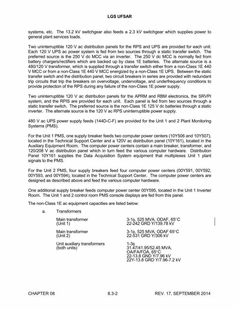
LGS UFSAR
CHAPTER 08 8.3-2 REV. 17, SEPTEMBER 2014
systems, etc. The 13.2 kV switchgear also feeds a 2.3 kV switchgear which supplies power to general plant services loads.
Two uninterruptible 120 V ac distribution panels for the RPS and UPS are provided for each unit. Each 120 V UPS ac power system is fed from two sources through a static transfer switch. The preferred source is the 250 V dc MCC via an inverter. The 250 V dc MCC is normally fed from battery chargers/rectifiers which are backed up by class 1E batteries. The alternate source is a 480/120 V transformer, which is supplied through a transfer switch either from a non-Class 1E 440 V MCC or from a non-Class 1E 440 V MCC energized by a non-Class 1E UPS. Between the static transfer switch and the distribution panel, two circuit breakers in series are provided with redundant trip circuits that trip the breakers on overvoltage, undervoltage, and underfrequency conditions to provide protection of the RPS during any failure of the non-Class 1E power supply.
Two uninterruptible 120 V ac distribution panels for the APRM and RBM electronics, the SRVPI system, and the RPIS are provided for each unit. Each panel is fed from two sources through a static transfer switch. The preferred source is the non-Class 1E 125 V dc batteries through a static inverter. The alternate source is the 120 V ac RPS uninterruptible power supply.
480 V ac UPS power supply feeds (144D-C-F) are provided for the Unit 1 and 2 Plant Monitoring Systems (PMS).
For the Unit 1 PMS, one supply breaker feeds two computer power centers (10Y506 and 10Y507), located in the Technical Support Center and a 120V ac distribution panel (10Y161), located in the Auxiliary Equipment Room. The computer power centers contain a main breaker, transformer, and 120/208 V ac distribution panel which in turn feed the various computer hardware. Distribution Panel 10Y161 supplies the Data Acquisition System equipment that multiplexes Unit 1 plant signals to the PMS.
For the Unit 2 PMS, four supply breakers feed four computer power centers (00Y591, 00Y592, 00Y593, and 00Y594), located in the Technical Support Center. The computer power centers are designed as described above and feed the various computer hardware.
One additional supply breaker feeds computer power center 00Y595, located in the Unit 1 Inverter Room. The Unit 1 and 2 control room PMS console displays are fed from this panel.
The non-Class 1E ac equipment capacities are listed below:
a. Transformers
Main transformer 3-1, 525 MVA, ODAF, 65C(Unit 1) 22-242 GRD Y/139.78 kV
Main transformer 3-1, 525 MVA, ODAF 65C(Unit 2) 22-531 GRD Y/306 kV
Unit auxiliary transformers 1-3(both units) 31.47/41.95/52.45 MVA,
OA/FA/FOA, 65C22-13.8 GND Y/7.96 kV22Y-13.8 GRD Y/7.96-7.2 kV

LGS UFSAR
CHAPTER 08 8.3-3 REV. 17, SEPTEMBER 2014
Station auxiliary (startup) 1-3transformer 36.96/49.28/61.6 MVA,(Unit 1) OA/FOA/FOA, 65C
230-14.18 Y/8.187 kV,LTC ±10% of 14.18 kV,automatic, on-line
Autotransformers, tertiary 2-3 OA/FOA/FOAwinding (startup) H 252/336/420 MVA, 65C(Unit 2) X 252/336/420 MVA, 65C
Y 57.4/76.5/95.7 MVA, 65C515 GRD Y/297.3-230 GRD Y/132.8-13.8 kV,LTC ±10% of 515 kVautomatic, on-line
Safeguard transformers 1-3(both units) 11.2/14.0 MVA, OA/FA,
65C 13.2-4.16 Y/2.4 kV,LTC ±10% of 4.16 kV,automatic, on-line
Transformers (Perkiomen 2-3Pumping Station) 5.6/7.0 MVA, OA/FA, 65�C(Common to Units 1 and 2) 34.4-4.16 Y/2.4 kV
Plant services transformers 1-3(both units) 5600/7000 kVA,
OA/FA, 65C,13.2-2.4 Y/1.386 kV
Regulating Transformer 1-3(startup) 35/46.667/58.333 MVA(Unit 2) OA/FA/FA, 65C
13.8 Y/7.97 -13.8 Y/7.97-4.815 kVLTC -10.3 to +19.7% of13.8 kV, automatic, on-line
b. Switchgear
13.2 kV Switchgear 1200/2500 A continuousrating, 750 MVA, 337,500 A rms symmetricalinterrupting rating
2.3 kV Switchgear 1200/2000 A continuousrating 250 MVA 3 class37,500 A rms symmetricalinterrupting rating

LGS UFSAR
CHAPTER 08 8.3-4 REV. 17, SEPTEMBER 2014
c. 440 V Unit load centers
Transformers 1000 kVA AA and1000/1333 kVA AA/FA,3, 60 Hz, 13200-480 GRDY/277 V
Horizontal Bus 1600 A continuous rating
Vertical Bus 600 A continuous rating
Breakers (metal clad) 22,000 A rms symmetrical,minimum interrupting rating
d. 440 V Unit load centers(Perkiomen Creek - commonto Units 1 and 2)
Transformers 300 kVA AA, 3, 60 Hz,4160-480 GRD Y/277 V
Horizontal Bus 600 A continuous rating
Vertical Bus 600 A continuous rating
Breakers (metal clad) 22,000 A rms symmetricalminimum interrupting rating
e. 440 V MCCs
Horizontal bus 600 A continuous rating,42,000 A rms symmetricalbracing
Vertical bus 300 A minimum continuous rating, 42,000 A rms symmetrical bracing
Breakers (molded-case) 22,000 A rms symmetrical,minimum interrupting rating
f. 120 V Instrument acdistribution panels
Buses 100/225A continuous rating10,000 A rms symmetricalbracing
Breakers (molded-case) 100 A frame size5,000 A rms symmetricalinterrupting rating

LGS UFSAR
CHAPTER 08 8.3-5 REV. 17, SEPTEMBER 2014
g. 120 V ac UPS andcomputer distribution panels
Buses 400 A continuous rating5,000 A rms symmetricalbracing
Fuses 200,000 A rms symmetricalinterrupting rating
8.3.1.1.2 Class 1E Ac Power System
The Class 1E ac power system is the portion of the onsite power system that is shown after the 4 kV nonsegregated bus in Drawings E-15 and E-16 at the incoming 4 kV breaker.
The Class 1E ac system distributes power at 4 kV, 440 V, and 208/120 V. The loads that are fed by this Class 1E ac system are divided into four divisions in each unit and are shown in Drawings E-15 and E-16. Each load division has its own distribution system and power supplies.
The 4 kV bus of each Class 1E load division is provided with connections to two offsite power sources, designated as preferred and alternate power supplies. In addition, provisions exist for connection to a third offsite power source through a spare transformer if there is a failure of one of the two offsite sources or either of the safeguard transformers. Diesel generators are provided as a standby power supply if there is a total loss of the preferred and alternate power supplies. Standby power supply is discussed in Section 8.3.1.1.3.
The Class 1E ac power system and its components, and the diesels and their auxiliaries, are located in seismic Category I structures that provide protection from the effects of tornadoes, tornado missiles, turbine missiles, and external floods. The Class 1E AC Power System and its components are designated Class 1E safety related, and the diesels and their required auxiliaries are designated safety related for procurement and quality assurance purposes and have been qualified for seismic and hydrodynamic loads as well as environmental conditions that they may experience during normal operation and postulated accidents.
None of the electrical equipment that is required to mitigate the effects of a design basis event will become submerged as a result of a LOCA. The only electrical equipment that may experience temporary submergence is penetration assembly JX230A, which becomes submerged during the pool-swell experienced during an SRV discharge. To ensure that suppression pool temperature indication which is monitored by this penetration is maintained during the pool-swell, the entire penetration is encased by an enclosure to a point above the maximum pool level, thereby assuring that the electrical portion of the penetration will not be affected by the pool-swell.
The following material describes the various features of the Class 1E ac power system.
8.3.1.1.2.1 Power Supply Feeder
Each Class 1E 4 kV switchgear is provided with a preferred and an alternate offsite power supply feeder and one standby diesel generator feeder. Each bus is normally energized by the preferred power supply. If the preferred power source is not available at the 4 kV bus, automatic transfer is
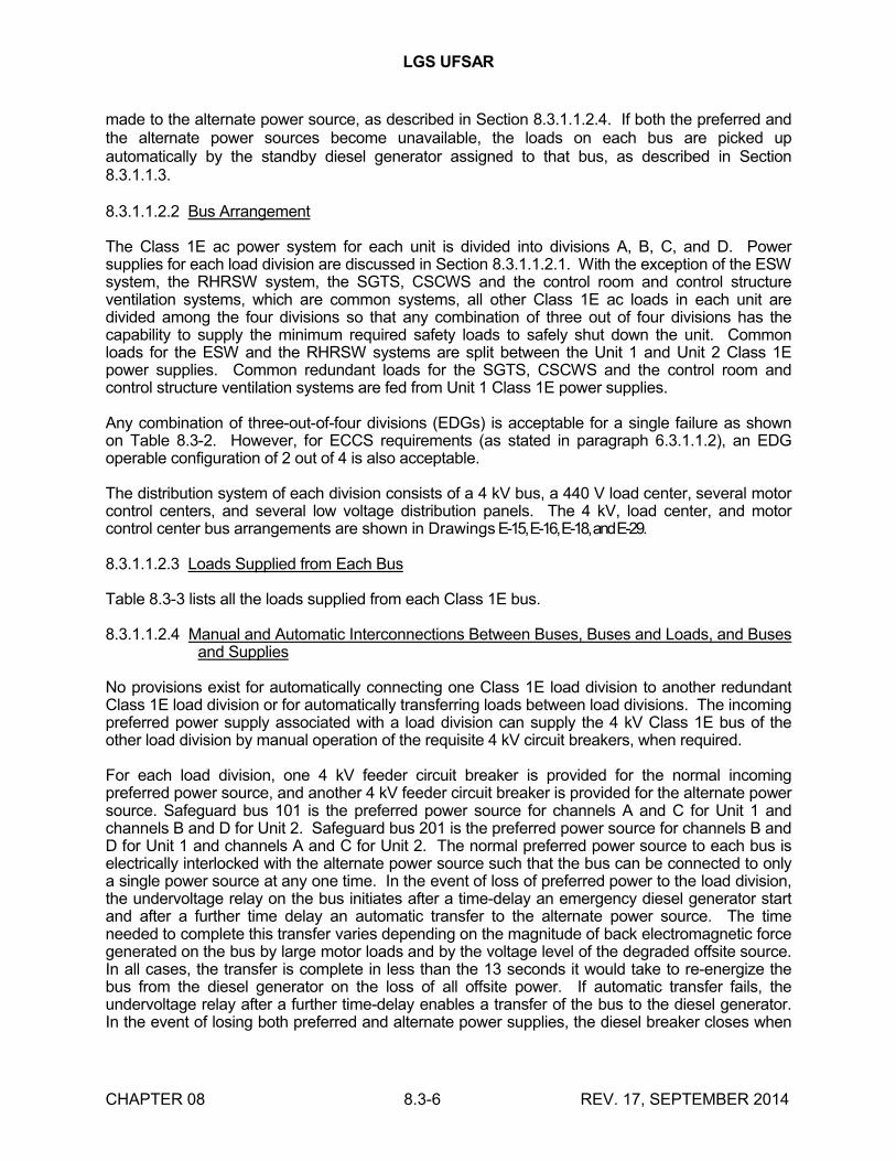
LGS UFSAR
CHAPTER 08 8.3-6 REV. 17, SEPTEMBER 2014
made to the alternate power source, as described in Section 8.3.1.1.2.4. If both the preferred and the alternate power sources become unavailable, the loads on each bus are picked up automatically by the standby diesel generator assigned to that bus, as described in Section 8.3.1.1.3.
8.3.1.1.2.2 Bus Arrangement
The Class 1E ac power system for each unit is divided into divisions A, B, C, and D. Power supplies for each load division are discussed in Section 8.3.1.1.2.1. With the exception of the ESW system, the RHRSW system, the SGTS, CSCWS and the control room and control structure ventilation systems, which are common systems, all other Class 1E ac loads in each unit are divided among the four divisions so that any combination of three out of four divisions has the capability to supply the minimum required safety loads to safely shut down the unit. Common loads for the ESW and the RHRSW systems are split between the Unit 1 and Unit 2 Class 1E power supplies. Common redundant loads for the SGTS, CSCWS and the control room and control structure ventilation systems are fed from Unit 1 Class 1E power supplies.
Any combination of three-out-of-four divisions (EDGs) is acceptable for a single failure as shown on Table 8.3-2. However, for ECCS requirements (as stated in paragraph 6.3.1.1.2), an EDG operable configuration of 2 out of 4 is also acceptable.
The distribution system of each division consists of a 4 kV bus, a 440 V load center, several motor control centers, and several low voltage distribution panels. The 4 kV, load center, and motor control center bus arrangements are shown in Drawings E-15, E-16, E-18, and E-29.
8.3.1.1.2.3 Loads Supplied from Each Bus
Table 8.3-3 lists all the loads supplied from each Class 1E bus.
8.3.1.1.2.4 Manual and Automatic Interconnections Between Buses, Buses and Loads, and Buses and Supplies
No provisions exist for automatically connecting one Class 1E load division to another redundant Class 1E load division or for automatically transferring loads between load divisions. The incoming preferred power supply associated with a load division can supply the 4 kV Class 1E bus of the other load division by manual operation of the requisite 4 kV circuit breakers, when required.
For each load division, one 4 kV feeder circuit breaker is provided for the normal incoming preferred power source, and another 4 kV feeder circuit breaker is provided for the alternate power source. Safeguard bus 101 is the preferred power source for channels A and C for Unit 1 and channels B and D for Unit 2. Safeguard bus 201 is the preferred power source for channels B and D for Unit 1 and channels A and C for Unit 2. The normal preferred power source to each bus is electrically interlocked with the alternate power source such that the bus can be connected to only a single power source at any one time. In the event of loss of preferred power to the load division, the undervoltage relay on the bus initiates after a time-delay an emergency diesel generator start and after a further time delay an automatic transfer to the alternate power source. The time needed to complete this transfer varies depending on the magnitude of back electromagnetic force generated on the bus by large motor loads and by the voltage level of the degraded offsite source. In all cases, the transfer is complete in less than the 13 seconds it would take to re-energize the bus from the diesel generator on the loss of all offsite power. If automatic transfer fails, the undervoltage relay after a further time-delay enables a transfer of the bus to the diesel generator. In the event of losing both preferred and alternate power supplies, the diesel breaker closes when
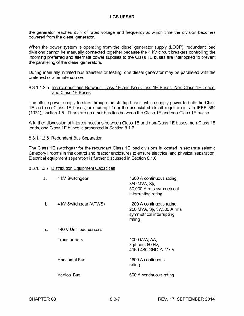
LGS UFSAR
CHAPTER 08 8.3-7 REV. 17, SEPTEMBER 2014
the generator reaches 95% of rated voltage and frequency at which time the division becomes powered from the diesel generator.
When the power system is operating from the diesel generator supply (LOOP), redundant load divisions cannot be manually connected together because the 4 kV circuit breakers controlling the incoming preferred and alternate power supplies to the Class 1E buses are interlocked to prevent the paralleling of the diesel generators.
During manually initiated bus transfers or testing, one diesel generator may be paralleled with the preferred or alternate source.
8.3.1.1.2.5 Interconnections Between Class 1E and Non-Class 1E Buses, Non-Class 1E Loads, and Class 1E Buses
The offsite power supply feeders through the startup buses, which supply power to both the Class 1E and non-Class 1E buses, are exempt from the associated circuit requirements in IEEE 384 (1974), section 4.5. There are no other bus ties between the Class 1E and non-Class 1E buses.
A further discussion of interconnections between Class 1E and non-Class 1E buses, non-Class 1E loads, and Class 1E buses is presented in Section 8.1.6.
8.3.1.1.2.6 Redundant Bus Separation
The Class 1E switchgear for the redundant Class 1E load divisions is located in separate seismic Category I rooms in the control and reactor enclosures to ensure electrical and physical separation. Electrical equipment separation is further discussed in Section 8.1.6.
8.3.1.1.2.7 Distribution Equipment Capacities
a. 4 kV Switchgear 1200 A continuous rating,350 MVA, 3,50,000 A rms symmetricalinterrupting rating
b. 4 kV Switchgear (ATWS) 1200 A continuous rating,250 MVA, 3, 37,500 A rmssymmetrical interruptingrating
c. 440 V Unit load centers
Transformers 1000 kVA, AA,3 phase, 60 Hz,4160-480 GRD Y/277 V
Horizontal Bus 1600 A continuousrating
Vertical Bus 600 A continuous rating

LGS UFSAR
CHAPTER 08 8.3-8 REV. 17, SEPTEMBER 2014
Breakers (metal clad) 22,000 A rms symmetrical,minimum interrupting rating
d. 440 V MCCs
Horizontal bus 600 A continuous rating42,000 A rms symmetricalbracing
Vertical bus 600 A continuous rating42,000 A rms symmetricalbracing
Breakers (molded-case) 22,000 A rms symmetrical,minimum interrupting ratingand 14,000 A rmssymmetrical with integralcurrent limiter
e. 120 V Instrument acdistribution panels
Buses 225 A continuous rating10,000 A rms symmetricalbracing
Breakers (molded-case) 100 A frame size5,000 A rms symmetricalinterrupting rating
8.3.1.1.2.8 Automatic Load Shedding and Sequential Loading
Shedding of the loads off the Class 1E buses is achieved by using undervoltage relays that automatically trip the breakers on bus undervoltage or a LOCA signal in the unit with which the loads are associated. Load sequencing is accomplished by using time-delay relays on individual breaker control circuits.
The following describes load shedding and sequential loading after a LOCA:
a. With offsite power available, all Class 1E 4 kV breakers on the unit with the LOCA, except for the RHR pump motor feeder breakers and incoming source breakers, are tripped. The required Class 1E loads are then started in a preset time sequence as shown on Table 8.3-1(b). Common loads supplied from the unit without the LOCA, which are required to support the unit with the LOCA, are also started.
b. For a total LOOP, all Class 1E 4 kV breakers on the unit with the LOCA are tripped and the required Class 1E loads are then started in a preset time sequence as shown on Table 8.3-1(a). All Class 1E 4 kV breakers on the non-LOCA unit are also tripped with the exception of the load center feeder breakers. Common loads supplied by the non-LOCA unit, which are necessary to support the LOCA unit, are

LGS UFSAR
CHAPTER 08 8.3-9 REV. 17, SEPTEMBER 2014
started automatically. All other 4 kV loads in the non-LOCA unit are started manually as required for emergency shutdown.
For further information, see Section 8.3.1.1.3.6.
8.3.1.1.2.9 Class 1E Equipment Identification
A clear identification is provided to distinguish between Class 1E and non-Class 1E equipment. Each division of the Class 1E cable and raceway is identified by a unique color and a numbering system. Section 8.3.1.3 discusses Class 1E and non-Class 1E equipment identification in detail.
8.3.1.1.2.10 Instrumentation and Control Systems for the Applicable Power Supply Identified
Power for the four divisions of Class 1E instrumentation and control circuits is supplied by the respective division of the Class 1E instrumentation and control distribution equipment. The power supplies for instrumentation and control circuits are described below.
a. Instrumentation - The instrumentation ac system supplies power for the Class 1E instruments.
Four independent Class 1E 208/120 V ac power supplies are provided to supply the associated four channels of the instruments. The four bus arrangement provides a separate electric power supply to each of the four channels that are electrically and physically isolated from the other channels. Each power supply consists of a 480-208Y/120 V transformer and one or more distribution panels. The 440 V power supply is provided by the corresponding 440 V Class 1E MCC.
b. Control Circuits - Control power for the 4 kV Class 1E switchgear is supplied by the Class 1E 125 V dc system, while load centers and MCCs use 120 V ac for control power.
Dc control power for the Class 1E switchgear is provided from Class 1E batteries of the same division. Four divisions of Class 1E batteries supply control power to the associated four divisions of the Class 1E switchgear. For a further description of the dc system, see Section 8.3.2.
For each Class 1E load center, control power is supplied from a control bus connected to the load center power bus through a control transformer.
MCC control power is supplied by individual control transformers connected to those breakers requiring control power. For selected control circuits, Class 1E 125 V dc control power is used to supplement the Class 1E 120 V ac supplied by individual control transformers.
8.3.1.1.2.11 Electric Circuit Protection Systems
Protective relay schemes and direct-acting trip devices on primary and backup circuit breakers are provided throughout the onsite power system to:
a. Isolate faulted equipment and/or circuits from unfaulted equipment and/or circuits

LGS UFSAR
CHAPTER 08 8.3-10 REV. 17, SEPTEMBER 2014
b. Prevent damage to equipment
c. Protect personnel
d. Minimize system disturbances
e. Maintain continuity of the power supply
The short-circuit protective system is analyzed to ensure that the various adjustable devices are applied within their ratings and set to be coordinated with each other to attain selectivity in their operation. The combination of devices and settings applied affords the selectivity necessary to isolate a faulted area quickly, with minimum disturbance to the rest of the system.
Each circuit breaker and protective relay is equipped with a visual indicator to identify its actuation.
To avoid spurious trips and to ensure correct selective operation of the protective devices and their associated breakers, minimum time intervals are maintained between the characteristic tripping curves of the various protective devices to account for pickup tolerances.
When coordinating inverse-time overcurrent relays, the time interval between relay characteristics is a minimum of 0.3-0.4 seconds. The interval consists of 0.08 seconds for circuit breaker operating time, 5 cycles, 0.10 seconds for relay overtravel, and 0.12-0.22 seconds for safety factor. The minimum time interval between relay characteristics and fuse characteristic curves is 0.2 seconds. The current pickup intervals between relay characteristics are selected to maintain tripping selectivity, which includes the separation margins required by relay pickup tolerances.
When coordinating low voltage power circuit breakers, molded-case circuit breakers and fuses, the characteristic curves generally do not overlap. In general, only a slight separation is made between the different characteristic curves because the curves represent minimum and maximum clearing times and include the tolerances of the protective device.
Per the LGS Fire Protection Plan, presented in Appendix 9A, Section 9A.6.1.1, all systems and components that are relied on for achieving safe shutdown receive power from the Class 1E ac distribution system or Class 1E dc power system. Offsite power may be credited as the source for the Class 1E ac distribution system for fire areas which do not require Alternative Shutdown and for which the offsite source(s) to the 4kV switchgear is not affected by fire damage. All circuits, both Class 1E and non-Class 1E, are individually protected by coordinated fault actuated protective devices. Proper coordination among these protection devices is discussed in Section 9A.6.1.1, and demonstrated by time-current coordination curves shown in Figures 9A-13 through 9A-20.
Time-current coordination curves for drywell penetrations are shown in UFSAR Figures 8.1-2 through 8.1-5.
Major types of protection measures employed include the following:
a. Bus differential relaying
A bus differential relay scheme is provided for each Class 1E 4 kV bus. These relays provide high speed clearing of internal bus faults by tripping all circuit breakers connected to the faulted bus.

LGS UFSAR
CHAPTER 08 8.3-11 REV. 17, SEPTEMBER 2014
b. Overcurrent relaying
Each Class 1E 4 kV bus feeder circuit breaker is equipped with three very inverse-time overcurrent relays and one inverse-time ground fault relay to sense, and protect the bus from, overcurrent condition and to provide backup for feeder circuit protective relays.
Each 4 kV motor feeder circuit breaker has three overcurrent relays, each with one long-time, one high dropout instantaneous, and one standard instantaneous element for overload, locked rotor, and short-circuit protection. Each breaker is also equipped with an instantaneous ground sensor relay. Each 4 kV Class 1E motor is also provided with an overload alarm.
For 4 kV Class 1E motors, the circuit inverse-time protection is set for overload alarm at approximately 115% of motor full load current for motors with service factor (SF) = 1.0 and at approximately 130% full load current for SF = 1.15. The high dropout instantaneous element is set at 175% full load current and will trip for locked rotor and short-circuit currents, provided the inverse-time element has operated. The standard instantaneous element is set at greater than or equal to 160% of motor locked rotor current for short-circuit trip.
Each Class 1E 4 kV supply circuit breaker to a 480 V load center transformer is protected by three extremely inverse-time overcurrent relays with long-time and instantaneous elements. An instantaneous overcurrent ground sensor relay provides sensitive ground fault protection.
For Class 1E 480 V load center transformers, the transformer primary inverse-time protection is set between 200% to 300% of the transformer AA rating.
c. Undervoltage relaying
Each 4 kV Class 1E bus is equipped with undervoltage relays for initiating a diesel generator start, an automatic transfer from the preferred to the alternate offsite power source, shedding the loads off the 4 kV Class 1E buses as described in Section 8.3.1.1.2.8, and loading the diesel generator when both the preferred and alternate offsite power sources are not available.
Each Class 1E 4 kV bus feeder is equipped with three undervoltage relays for starting the diesel generator and automatic transfer to an alternate source upon sensing degraded grid voltage. Section 8.1.6.3.6 gives a description of the degraded grid voltage monitoring system. This design is in compliance with the intent of BTP PSB1.
d. Diesel generator differential relaying
Each diesel generator is equipped with differential relaying protection. This circuitry provides high speed disconnection to prevent severe damage in case of diesel generator internal faults.
e. 440 V Load center protection

LGS UFSAR
CHAPTER 08 8.3-12 REV. 17, SEPTEMBER 2014
Each load center circuit breaker is equipped with integral, solid-state, adjustable,direct-action trip devices providing instantaneous and/or inverse-time overcurrent protection. Motor feeders are equipped with solid-state adjustable instantaneous and long-time overcurrent trip devices.
The overcurrent devices for breakers supplying 440 V MCCs are set to protect the feeder cables from short-circuit and thermal damage and to be selective with downstream protective devices.
Motor feeder long-time overcurrent devices are set at 145% to 150% motor full load current for motors with service factor (SF) = 1.15, and 130% to 135% full load current for motors with SF = 1.0. The instantaneous trip is set greater than or equal to 160% motor locked rotor current. The time-delay setting is adjusted for the motor characteristics such that acceleration is permitted, while protecting the motor for a locked rotor condition and thermal overload.
Each Class 1E load center feeder circuit breaker supplying non-Class 1E MCCs is equipped with an instantaneous undervoltage relay, which is set for pickup at 80% and dropout adjustable between 30% and 60% of nominal voltage.
f. 440 V MCC protection
Molded-case circuit breakers provide inverse-time overcurrent and/or instantaneous short-circuit protection for all connected loads. For motor circuits, the molded-case circuit breakers are equipped with an adjustable instantaneous magnetic trip function only. Motor thermal overload protection is provided by the heater element trip unit in each phase of the motor feeder circuit. The molded-case breakers fornonmotor feeder circuits provide thermal inverse-time overcurrent protection and instantaneous short-circuit protection. The thermal overload trip units for safety-related MOVs are bypassed in accordance with Section 8.1.6.1.19.
Thermal overload heater elements for Class 1E 460 V continuous-duty motors are selected taking into account the applicable ambient temperature compensation factor, voltage considerations and -10% manufacturing tolerance. The magnetic instantaneous trip on the molded-case breaker is set at approximately 200% locked rotor current to override the motor locked rotor current and to provide short-circuit protection. However, the final instantaneous trip setting may deviate from these guidelines based on test data obtained by field personnel.
The thermal magnetic breakers for nonmotor feeder circuits are set to have a thermal pickup at approximately 125% full load current and a magnetic instantaneous trip setting in excess of the load inrush current.
8.3.1.1.2.11.1 The information from this section has been relocated to the TRM.
8.3.1.1.2.12 Testing of the Ac System During Power Operation
All Class 1E power system equipment for which the Technical Specifications require periodic testing more frequently than every 24 months is provided with means to perform the required testing during power operation.

LGS UFSAR
CHAPTER 08 8.3-13 REV. 17, SEPTEMBER 2014
8.3.1.1.2.13 Power Systems and Equipment Shared Between Units
Each unit is provided with separate and independent onsite Class 1E ac power systems. The Class 1E power system for each unit consists of four independent Class 1E buses, powered by four independent diesel generators, which provide power to four divisions of Class 1E loads. The RHRSW and the ESW systems are considered common systems because each system supplies two independent cooling water loops which are common to both units. However, even though they are considered common systems, there is redundant equipment for these systems in each unit. The redundant equipment in each unit is powered by independent diesel generators in each unit and has the capacity to supply 100% of the required cooling water per unit. The SGTS, CSCWS and the control room and control structure ventilation systems are common systems, each with two 100% capacity redundant trains with common redundant components in each train powered from an independent diesel generator in Unit 1.
8.3.1.1.3 Standby Power Supply
The standby power supply for each division consists of one diesel generator set complete with accessories and fuel storage and transfer systems. Each diesel generator is connected to only one 4 kV Class 1E bus and is interlocked to prevent parallel operation during LOOP. The four Class 1E buses for each reactor unit are operated as separate buses (split bus system) and are not synchronized. Each diesel generator set is operated independently (from the other sets) and is disconnected from the utility power system, except during tests.
Each unit has four channels of standby power supply and four load divisions. With the exception of the standby power supply requirements for the ESW system, the RHRSW system, the SGTS, the CSCWS and the control room and control structure ventilation systems, which are common systems, the operation of three out of four channels of the standby power supply in each unit is adequate to satisfy minimum Class 1E load demand caused by a LOCA or LOOP sources. Common loads for the ESW and the RHRSW systems are split between Unit 1 and Unit 2 standby power supplies. Common redundant loads for the SGTS, the CSCWS and the control room and control structure ventilation systems are fed from Unit 1 standby power supplies. A detailed discussion of the load demand on each diesel, which includes load characteristics, load sequencing, bus assignments, etc., is covered in Section 8.3.1.1.3.6.
Any combination of three-out-of-four divisions (EDGs) is acceptable for a single failure. However, for ECCS requirements (as stated in paragraph 6.3.1.1.2), an EDG operable configuration of 2 out of 4 is also acceptable.
The diesel generators are capable of supplying power to the loads necessary to shut down and cool down the associated unit safely. The diesel engine is a 12-cylinder, model 38-TD8-1/8 colt. The generator is a single bearing bracket, model TGZDJ Beloit Power Systems/Fairbanks Morse. Each diesel generator is rated at 2850 kW for continuous operation and at 3135 kW for two hours of short-time operation in any 24 hour period and is qualified to a 100 start test. The diesel generators are selected so that their ratings satisfy the requirements of Regulatory Guide 1.9, as discussed in Section 8.1.6.1.2. In addition, the diesel generators are capable of operating for extended periods of time at either low load or unloaded in the case of a LOCA occurring with the availability of offsite power. For extended periods of low load operation (up to 30% load), the diesel generators are operated at 50% load or greater for at least one hour in every 12 hour period. The manufacturer's recommendations will be followed for loading up to

LGS UFSAR
CHAPTER 08 8.3-14 REV. 17, SEPTEMBER 2014
50% load. This prevents possible accumulation of combustion and lube oil products in the exhaust system. If a LOCA should occur and offsite power is available, the diesel generators in the unit experiencing the LOCA would start automatically and run unloaded. After the offsite power grid, reactor parameters, and support systems have been stabilized and the LOCA signal reset, the unloaded diesel generators would be manually stopped and returned to standby. Even though the diesel generators would not be expected to run in this condition for an extended period of time, the capability to manually load the diesel generators to remove possible combustion and lube oil products from the exhaust system is provided.
The following sections discuss the functional aspects of the diesel generator.
8.3.1.1.3.1 Starting Initiating Circuits
The diesel generators are started by any of the following conditions:
a. LOOP at the 4 kV Class 1E buses
b. Low reactor water level (associated unit only)
c. High drywell pressure coincident with low reactor pressure (associated unit only)
d. Manual actuation of the start/automatic/stop control switch in the control room when the remote/local selector switch is in the REMOTE position
e. Manual actuation of the start/stop control switch on a local control station when the remote/local selector switch is in the LOCAL position
Two redundant control/starting circuits are provided for each diesel generator. The failure of one circuit does not prevent the respective diesel generator from starting or from operating continuously.
Although started automatically, the diesel generators are not automatically connected to their associated 4 kV Class 1E buses until the generator voltage and frequency are established, the breakers connecting the emergency buses to the offsite sources are tripped, and the bus voltage is zero. The diesel generator is stopped by the operator after he/she determines that continued operation of the diesel is not required.
8.3.1.1.3.2 Diesel Starting Mechanism and System
The diesel generator start system is described in Section 9.5.6. Each diesel engine is provided with immersion heaters in the engine jacket water and the lube oil system to maintain the engine coolant and lube oil temperature at an operable level for fast and reliable starting of the diesel engines. The standby jacket coolant heater and the standby jacket coolant circulating pump are interlocked for simultaneous operation when the jacket water temperature drops below the preset temperature and the engine is below the preset speed. The standby lube oil heater and the standby lube oil circulating pump are interlocked for simultaneous operation when the oil is below a preset temperature and the engine is below a preset speed. See Sections 9.5.5 and 9.5.7 for further description.

LGS UFSAR
CHAPTER 08 8.3-15 REV. 17, SEPTEMBER 2014
8.3.1.1.3.3 Tripping Devices
Each diesel and/or related generator circuit breaker, while supplying loads during a LOCA, are tripped only for the following conditions:
a. Engine overspeed
b. Diesel generator differential overcurrent
c. 4 kV bus differential overcurrent
When the diesel generator receives an emergency (LOCA) start signal, the LOCA relay is energized and the following trips are bypassed; specifically, the generator circuit breaker trip and/or engine shutdown functions for the following abnormal conditions will be overridden:
a. Generator phase overcurrent
b. Generator ground neutral overcurrent
c. Antimotoring
d. Jacket coolant high temperature
e. Jacket coolant low pressure
f. Lube oil high temperature
g. Lube oil low pressure
h. Deleted
i. 4 kV bus phase overcurrent
j. 4 kV bus ground overcurrent
The bypass circuitry contains the following:
a. A NORMAL/TEST switch is provided at the generator control panel to arm the bypassed engine shutdown functions during simulated LOCA testing.
b. The following abnormal conditions of the bypassed parameters are annunciated in the main control room:
1. Generator phase overcurrent
2. Generator ground neutral overcurrent
3. Diesel generator protective trips not bypassed for LOCA test.

LGS UFSAR
CHAPTER 08 8.3-16 REV. 17, SEPTEMBER 2014
The following abnormal conditions of the bypassed parameters are annunciated at the local control panel and at a common DIESEL GENERATOR TROUBLE alarm in the main control room.
1. Jacket coolant temperature high
2. Jacket coolant pressure low
3. Lube oil temperature high
4. Lube oil pressure low
5. Diesel generator protective trip not bypassed for LOCA test.
c. Following a simulated LOCA test (after the LOCA signal is reset and the engine is stopped), the bypass trip circuit is manually reset by returning to NORMAL at the local panel. This rearms the trips for routine testing and permits them to be bypassed by an actual LOCA start signal.
The annunciator system for these trips provides indication of first out alarm. For example, when one or more abnormal conditions are annunciated at the local control panel, the DIESEL GENERATOR TROUBLE alarm in the main control room notifies the operator of a problem. The local control panel gives indication of which abnormal condition occurred first.
Directional overcurrent (reverse power) protection is provided but is permitted to trip the 4 kV bus breakers only during operation of the diesel generator in parallel with the preferred power supply during manually initiated testing.
To prevent spurious tripping of the engine due to malfunction of an engine protective device, three independent sensors are provided and connected in a two-out-of-three tripping logic for all trip conditions except engine overspeed and protective relays. The overspeed trip device is a simple, highly reliable mechanical device for which two-out-of-three tripping logic is unnecessary.
The starting circuit is equipped with a "fail to start" relay that interrupts the starting of the diesel generator if the diesel generator does not reach 200 rpm within a preset time following a start initiation. The "fail to start" relay causes the "start relay" and the "ready for auto start" relay to become deenergized, and provides a failure to start alarm both locally and in the main control room. Energizing the "fail to start" relay will prevent a subsequent auto or manual start. After correcting the trouble, the "fail to start" relay must be reset at the diesel generator by manuallyoperating the engine shutdown reset located at the diesel generator local control panel.
8.3.1.1.3.4 Breaker Interlocks
Interlocks are provided in the closing and tripping of the 4 kV Class 1E circuit breakers to protect personnel and equipment from the following conditions:
a. Automatic energizing of electric devices or loads during maintenance
b. Automatic closing of the diesel generator breaker to any energized or faulted bus

LGS UFSAR
CHAPTER 08 8.3-17 REV. 17, SEPTEMBER 2014
c. Connecting two sources out of synchronism
8.3.1.1.3.5 Control Permissive
A single key-operated local/remote selector switch at the local control panel is provided for each diesel generator to block automatic start signals when the diesel is out-of-service for maintenance. An annunciator alarm in the control room indicates DIESEL NOT IN AUTO when the switch is not in the REMOTE position.
A control switch in the control room and a local control switch on the local control panel in the diesel generator room are provided to allow manual starting of the diesel when all protective systems are permissive. During periodic diesel generator tests, permissives and interlocks are designed to permit manual synchronizing and loading of the diesel generator with either offsite power source.
8.3.1.1.3.6 Loading of Diesel Generators
The diesel generators are designed to start and attain the required voltage and frequency within 10 seconds. The generator, static exciter, and voltage regulator are designed to permit the unit to accept the load and to accelerate the motors in the sequence and time requirements shown in Table 8.3-1(a). LGS does not use an emergency load sequencer associated with the offsite and onsite power sources. Sequencing of loads on the Class 1E buses is achieved by individual time-delay relays for each load. There are no short-circuits that could render both the onsite and offsite power sources unavailable.
Voltage drop calculations on starting large motors have been made to ensure proper acceleration of the pumps under the required conditions for core cooling after a DBA. Proper control and timing relays are provided so that each load is applied automatically at the proper time and in the starting sequence indicated in Table 8.3-1(a). When the automatic loading sequence of the Class 1E loads is completed, the operator may manually add additional loads as assigned in Table 8.3-3 but these loads should not exceed the available capacity of the diesel generator as limited by fuel consumption. The operator may also trip Class 1E loads if their continued operation is not necessary. Load shedding before diesel generator operation is discussed in Section 8.3.1.1.2.8.
Table 8.3-2 summarizes the maximum loading conditions of any one diesel generator for the situation in which all four diesel generators in each unit are in service and also for the situation in which any one of the eight diesel generators is out-of-service. Tables 8.3-3, 8.3-9 through 8.3-17 provide detailed backup data for the summary of Table 8.3-2. Table 8.3-3 shows the assignment of individual loads to the eight emergency buses and the eight diesel generators. Tables 8.3-9 through 8.3-17 indicate how heavily a diesel generator may be loaded during a Unit 1 DBA and a spurious
LOCA in Unit 2 followed by an emergency shutdown of Unit 2 for time intervals of 0-10 minutes, 10-60 minutes, and beyond 60 minutes. These tables show that the calculated maximum loading of any one diesel generator for all time periods following a DBA is within the DEMA continuous rating of typical diesel generators that have been qualified and furnished for nuclear standby service. These tables also show that the loading is within the rating of each diesel generator as limited by fuel consumption.
8.3.1.1.3.7 Testing

LGS UFSAR
CHAPTER 08 8.3-18 REV. 17, SEPTEMBER 2014
Diesel generator testing consists of the following:
a. Preoperational test - Each diesel generator is tested at the site before reactor fuel loading, in accordance with the requirements of Chapter 14.
b. Periodic test - The diesel generator surveillance test program will provide for a minimum loading of 25% of rated load.
Equipment will undergo periodic surveillance testing in accordance with LGS Technical Specifications. This testing is implemented as part of the surveillance test program.
The manufacturer technical manuals and preventive maintenance recommendations will be reviewed and appropriate preventive maintenance actions will be incorporated into the preventive maintenance program. Equipment maintenance histories will be kept for the diesel generators, and completed preventive maintenance will be documented in the history. This will aid in the detection of repetitive failures that may be analyzed for corrective action directed at the cause of failure. The preventive maintenance program will be enforced and controlled as delineated in the administrative procedure for this program.
Within the maintenance program procedures, a "Return-to-Normal" section will be included to specify steps necessary to return the diesel generator system to operational status. After completion of "Return-to- Normal" section and required surveillance testing, the unit can be returned to the control room operator in automatic standby mode.
If the diesel generator is running in the test mode and an emergency demand start diesel signal is received, the diesel generator controls will automatically convert the governor from the droop to the isochronous mode and the automatic voltage regulator to the isolated mode. The generator breaker will also be automatically tripped if offsite power is available. Thus, the control of the diesel generator is returned to the automatic control system and loading may proceed as discussed in Sections 8.3.1.1.2.8 and 8.3.1.1.3.6.
Compliance with Regulatory Guide 1.108, "Periodic Testing of Diesel Generator Units Used as Onsite Electric Power Systems at Nuclear Power Plants," is discussed in Section 8.1.6.1.20.
8.3.1.1.3.8 Fuel Oil Storage and Transfer System
The diesel generator fuel oil system is described in Section 9.5.4.
8.3.1.1.3.9 Diesel Generator Cooling and Heating Systems
The diesel generator cooling and heating systems are discussed in Section 9.5.5.
8.3.1.1.3.10 Instrumentation and Control Systems for Standby Power Supply

LGS UFSAR
CHAPTER 08 8.3-19 REV. 17, SEPTEMBER 2014
Control hardware is provided in the control room for each diesel generator for the following operations:
a. Starting and stopping
b. Manual synchronization
c. Frequency and voltage adjustment
Control hardware is provided at each of the local control panels for the following operations:
a. Starting and stopping
b. Frequency and voltage adjustment
c. Automatic or manual voltage regulator selection
d. Local or remote control selection (key-operated switch)
Electric metering instruments are provided in the control room for surveillance of the following diesel generator parameters:
a. Voltage
b. Current
c. Frequency
d. Power output (watts)
e. Reactive power output (var)
f. Field voltage
g. Field current
Electrical metering instruments are provided at the local control panel for surveillance of the following diesel generator parameters:
a. Voltage
b. Current
c. Frequency
d. Power output (watt)
e. Reactive power output (var)
f. Energy output (watt-hour)

LGS UFSAR
CHAPTER 08 8.3-20 REV. 17, SEPTEMBER 2014
g. Field voltage
h. Field current
The following abnormal diesel engine and generator conditions are annunciated at the local control panel:
a. Lube oil pressure low
b. Lube oil keep-warm failure
c. Lube oil temperature high
d. Lube oil filter differential pressure high
e. Lube oil strainer differential pressure high
f. Lube oil level low
g. Lube oil or jacket water circulating pump failure
h. Jacket water keep-warm failure
i. Jacket water temperature high
j. Jacket water expansion tank level low
k. Jacket water pressure low
l. Starting air pressure low
m. Fuel oil pressure low
n. Fuel oil strainer differential pressure high
o. Fuel oil filter differential pressure high
p. Fuel oil day tank level low
q. Fuel oil day tank level high
r. Overspeed trip
s. Crankcase pressure high
t. Drip pan/dirty fuel oil tank level high
u. Start failure

LGS UFSAR
CHAPTER 08 8.3-21 REV. 17, SEPTEMBER 2014
v. Not ready for autostart
w. Generator stator temperature high
x. Generator bearing temperature high
y. Generator field ground
z. Generator loss of excitation
aa. Generator overexcitation
bb. Field flash voltage loss
cc. Emergency stop
dd. Dc fuel pump running
ee. Fuel oil transfer strainer differential pressure high
ff. 480 V ac auxiliary power off
gg. 125 V dc control power off
hh. Dc fuel pump power off
ii. Generator overvoltage
jj. Switch not in auto
kk. Fuel oil day tank temperature high
ll. Diesel generator protective trips not bypassed for LOCA test
mm. Intercooler coolant pressure low
nn. Fire/local control diff/ground trip bypass for 1AG501 onlyFire/local control for 2AG501 only
oo. Diesel generator exhaust heat tracing trouble
The following abnormal diesel engine and generator conditions are annunciated at the main control panels:
a. Diesel generator trouble (for alarms (a) through (oo), above)
b. Diesel generator differential/ground lockout
c. Generator overcurrent

LGS UFSAR
CHAPTER 08 8.3-22 REV. 17, SEPTEMBER 2014
d. Generator neutral overcurrent
e. Diesel generator not in auto
f. Diesel generator failed to start
g. Diesel generator fuel oil storage tank high or low
h. Diesel generator not reset
i. Diesel generator protective trip not bypassed for LOCA test
8.3.1.1.3.11 Prototype Qualification Testing
To confirm the ability of the diesel generator to perform as required, in September 1968 the diesel generator manufacturer conducted a series of tests designed to:
a. Simulate the conditions experienced during nuclear plant protection service
b. Record performance under such simulated conditions
c. Allow the use of recorded performance data to design optimized generator and excitation system
d. Demonstrate starting and load acceptance reliability
The details of the motor starting test program are covered in Reference 8.3-1.
The diesel generator manufacturer has extensive operational experience with skidded control systems, including the many nuclear protection units already tested and delivered.
As discussed in Sections 1.8 and 8.1.6.2, LGS is committed to Regulatory Guide 1.9 (Rev. 0) and IEEE 387 (1972). The diesel generators, therefore, are not required to pass a 300 consecutive start qualification test. However, the 12-cylinder model 38-TD8-1/8 Colt diesel engine used at LGS was qualified to a 100 start test conducted in 1968. This model engine has been used in the following plants that have received Operating Licenses:
Robinson 2 Duane ArnoldPrairie Island 1 & 2 North Anna 1 & 2Vermont Yankee Millstone 1 & 2Three Mile Island 1 & 2 Farley 1 & 2Calvert Cliffs 1 & 2 Arkansas Nuclear One, 2Crystal River 3 PBAPS 2 & 3E.I. Hatch 1 & 2 Fermi 2
The LGS diesel generators are nearly identical to the diesel generators used to demonstrate start and load acceptance reliability tests. The differences are that LGS diesel generator units have tubular heat exchangers while the test unit was radiator-cooled, and the LGS units have combustion air that passes from the turbocharger to the blower while the order is reversed for the

LGS UFSAR
CHAPTER 08 8.3-23 REV. 17, SEPTEMBER 2014
test unit. These differences are judged to be an improvement of reliability and load acceptance capability. Therefore, the tests are applicable to the LGS diesel generator units.
8.3.1.1.3.12 Conditions Prohibiting Diesel Generator Automatic Emergency Start and Associated Main Control Room Annunciators
Two groups of conditions render the diesel generator incapable of responding to an automatic start signal:
a. Abnormal conditions that may prevent start or cause trip or impede sustained operation
b. Control switch(es) in incorrect positions
The following is a tabulation of such conditions for both of these groups:
a. Abnormal Conditions
1. Engine overspeed
2. Generator differential overcurrent
3. 4 kV bus differential overcurrent
4. Generator antimotoring relay operation
5. Generator phase overcurrent
6. Generator neutral overcurrent
7. Lube oil low pressure
8. Lube oil high temperature
9. Jacket coolant low pressure
10. Jacket coolant high temperature
11. Failure to start relay operation
12. Crankcase high pressure
13. Diesel cell fire protection system activated(1)
14. Loss of 125 V dc control voltage to diesel control panel
15. Loss of 125 V dc to field flashing contacts
16. Loss of 125 V dc control voltage to 4 kV bus breakers and/or diesel generator breaker
___________________

LGS UFSAR
CHAPTER 08 8.3-24 REV. 17, SEPTEMBER 2014
(1) Fire protection system actuation will not prevent an automatic start of the diesel generator, but sustained operation cannot be guaranteed.
17. 4 kV bus breakers and/or diesel generator breaker racked out
18. ESW valves closed
19. Starting air pressure low
20. Nonsafeguard 4 kV loads on 4 kV bus with loss of breaker trip voltage
b. Control Switch Incorrect Positions
21. Remote/local selector switch in LOCAL
22. Exciter shutdown reset switch in SHUTDOWN
23. Engine shutdown reset switch not RESET
24. Emergency stop switch in STOP
25. Generator 4 kV breaker control switch in PULL-TO-LOCK
26. Diesel control switch in PULL-TO-LOCK
27. Diesel start logic bypass switches (two of two per diesel) in BYPASS
The following annunciator legends are provided in the control room for diesel generator alarms for each diesel generator:
1. DG breaker trip
2. DG differential/ground lockout
3. Diesel failed to start
4. Diesel not in AUTO
5. Diesel running
6. DG breaker autoclose
7. DG not RESET
8. DG trouble
9. Standby ac power system out-of-service
10. Generator neutral overcurrent

LGS UFSAR
CHAPTER 08 8.3-25 REV. 17, SEPTEMBER 2014
11. DG protection trip not bypass for LOCA test
12. Generator overcurrent
13. Fire protection alarm panel 00C926 Trouble(common for all diesel generators)
For each of the conditions listed above (conditions 1-26), the following annunciators are received in the control room:
Condition Alarms
1 1, 82 1, 23 Bus Diff/Overcurrent Lockout4 15 1, 126 1, 107 1, 88 1, 89 1, 810 1, 811 3, 812 813 1314 815 816 917 918 919 820 921 4, 7, 8, 922 4, 7, 8, 923 7, 924 7, 8, 925 926 427 8
Each condition that brings up the system out-of-service alarm (#9) lights an indicating light on the system vertical board in the control room to allow the operator to distinguish what condition has caused the alarm.
The following control room annunciators that were listed above are also triggered by the indicated conditions that were not listed above:
Annunciator Conditions

LGS UFSAR
CHAPTER 08 8.3-26 REV. 17, SEPTEMBER 2014
DG Trouble • All conditions that alarm at the local diesel annunciator panel. These conditions are listed in Section 8.3.1.1.3.10.
Standby AC Power System • Bus undervoltage relays inOut-of-Service test/loss of voltage
• Safeguard load center breaker not connected/loss of control voltage
• Out-of-service alarm manually initiated
Diesel Not In Auto • Any of the following control switches are not in AUTO:- Jacket coolant heater- Coolant circulating pump- Lube oil heater- Lube oil circulating pump- Generator space heater- Dc auxiliary fuel oil pump
There are no conditions that render the diesel generator incapable of starting that are not alarmed in the control room.
8.3.1.1.3.13 The material in this Section has been rewritten and relocated to Section 13.2.1.7.
8.3.1.1.4 Electrical Equipment Layout
Class 1E switchgear, load centers, MCCs, and distribution panels of redundant channels are in separate rooms or are spatially separated by a predetermined safety distance or barrier. They are located in the reactor enclosure, the control enclosure, or the spray pond pumphouse.
Standby diesel generators, related Class 1E MCC’s, and associated equipment are in separate rooms of the seismic Category I diesel generator enclosure. Each room is provided with a separate ventilation system.
The diesel generators do not generate harmful torsional vibrations when operating at any speed from 0% to 115% of rated speed. The engine gauge panel is located on the engine generator skid; however, it is mounted in a cradle on isolation springs. Colt (the manufacturer) has successfully used this method of mounting engine gauge boards for several years. Further, items critical to the continued operation of the unit are not mounted in the gauge panel. The annunciator and other sensitive items are located in freestanding electrical control panels. The control panel is physically separated from the diesel generator.
The following electrical equipment however, is located on the diesel generator skid:
a. Generator terminal box containing connections from the diesel generator to the local control panel.
b. Generator neutral box containing the connectors from the generator neutral grounding resistor.

LGS UFSAR
CHAPTER 08 8.3-27 REV. 17, SEPTEMBER 2014
c. Motor starter and heater control panel - All pump motors have automatically controlled magnetic starters, and the keep-warm heaters have automatically controlled contactors. The starter and contactors for the following motors and heaters are located in the starter panel at the generator end of the skid:
1. Jacket coolant heater
2. Jacket coolant circulating pump
3. Lube oil heater
4. Lube oil circulating pump
5. Generator space heater
6. Dc auxiliary fuel oil pump
d. Circuit breaker panel board - The following ac equipment on the skid is protected by circuit breakers that are located in the circuit breaker panel at the generator end of the skid:
1. Jacket coolant heater
2. Jacket coolant circulating pump
3. Lube oil heater
4. Lube oil circulating pump
5. Prelube pump
6. Generator space heater
e. Engine gauge panel - The following instruments are mounted in the engine gauge panel at the turbocharger end of the skid:
Instrument Monitoring Function
6 Duplex Pressure Gauges • Jacket water pump discharge pressure duplexed with air cooler coolant heat exchanger outlet pressure.
• Fuel oil pressure upstream and downstream of the line filter in the discharge piping of the engine-driven fuel oil pump.
• Fuel oil pressure upstream and downstream of the line filter in the discharge piping of the motor-driven fuel oil pump.

LGS UFSAR
CHAPTER 08 8.3-28 REV. 17, SEPTEMBER 2014
• Engine inlet lube oil pressure duplexed with engine-driven oil pump discharge pressure.
• Upper engine header pressure duplexed with the turbo-charger oil pressure.
• Starting air pressure upstream of both air start valves.
2 Differential Pressure • Basket strainerIndicators differential pressure(mounted on separate adjacent on the engine-drivegauge panel) fuel oil pump.
• Basket strainer differential pressure on the motor-driven fuel oil pump.
1 Simple Pressure Gauge • Scavenging air blower discharge pressure.
2 U-tube manometers • Crankcase pressure.• Turbocharger inlet pressure.
3 Duplex temperature gauges • Engine suction lube oil temperature duplexed with the engine-driven pump discharge lube oil temperature.
• Jacket water temperature on both the engine-driven pump suction and the header discharge.
• Scavenging air blower discharge temperature duplexed with the air cooler coolant inlet temperature.
1 15-point pyrometer • Points 1 to 12 measure the individual cylinder exhaust temperatures, points 13 and 14 measure the turbocharger inlet temperatures, and Point 15 measures the combined exhaust temperature.
1 Tachometer • Provides local indication of engine rpm.
1 Indicating Light • Verifies that the local alarm circuits are armed.
Equipment associated with these instruments is housed within the engine gauge panel enclosure and is accessed through a fully gasketed dust-tight door.

LGS UFSAR
CHAPTER 08 8.3-29 REV. 17, SEPTEMBER 2014
The entire panel assembly is mounted in a cradle on isolation springs such that vibration-induced loads will not affect the performance of the instrumentation. Also, no items that are critical to the operation of the diesel under emergency conditions are housed within this enclosure.
f. Dc control relay and terminal box - The following relays are found in the relay and terminal box located at the generator end of the skid:
1. Emergency start relays
2. Normal start relays
3. Other control relays
4. Coolant temperature high switch
5. Coolant pressure low switch
6. Lube oil temperature high switch
7. Lube oil pressure low switch
8. Alarm relays
The relay and terminal box is mounted at the generator end of the skid. The box is not mounted on an isolation spring; however, the box is anchored to the skid at its base and supported at the top by two lengths of angle iron.
This is the manufacturer's standard design for mounting this box on the diesel generator skid. This box is supported and mounted to prevent any vibration-induced damage of the relays. The manufacturer has shown by over 20 years of use that this support design adequately protects the internal components in the relay and terminal box from harmful vibration levels.
The seismic qualification of the relays in the relay and terminal box has been addressed in the equipment qualification program, and the information is contained in the dynamic qualification package for the diesel generators. Vibrational aging was not performed on these relays as there is no valid method of performing accelerated aging for vibrational effects and because the vibrational levels which these relays may see have been shown through operating experience as not having any detrimental effects on the operation of these relays.
The licensee contacted several other nuclear stations which employ the same mounting design of the relay and terminal box as LGS. The stations contacted reported that there have been no vibration induced failures of the relays in question. In addition, the failure record at the stations contacted indicates that there have been no problems with the relays installed in the relay and terminal box.
LGS UFSAR
CHAPTER 08 8.3-30 REV. 17, SEPTEMBER 2014
The manufacturer, who is notified if there are any problems with the diesel generator equipment, stated that no vibration induced failures have been reportedby any station.
For the reasons listed above, we believe that the relay and terminal box is adequately supported and that the components in this box are proven by experience to be protected against harmful vibration levels.
The above described methods of mounting have been the manufacturer's standard design for over 20 years. Neither the manufacturer nor the applicant, whose PBAPS units have been in service for about 10 years, have reported any vibration-induced failures in any of the components mounted on the diesel generator skid.
8.3.1.1.5 Design Criteria for Class 1E Equipment
The following design criteria are applied to the Class 1E equipment supplied from the onsite ac power system:
a. Motor size - Motor size (horsepower capability) is equal to or greater than the maximum horsepower required by the driven load under normal running, run-out, or discharge valve (or damper) closed condition.
b. Minimum motor accelerating voltage - The electrical system is designed so that the total voltage drop during the start of the last largest motor on the system is less than 25% and 20% of the nominal bus voltage at the 4 kV and 440 V buses, respectively. The Class 1E motors are specified with accelerating capability at 80% nominal voltage at their terminals for 460 V motors and 75% for 4 kV motors.
c. Motor starting torque - The motor starting torque is capable of starting and accelerating the connected load to normal speed within sufficient time to perform its safety function for all expected operating conditions, including the design minimum terminal voltage.
d. Minimum motor torque margin over pump torque through accelerating period - The minimum motor torque margin over pump torque through the accelerating period is determined by using actual pump torque curves and calculated motor torque curves at 75% or 80% terminal voltage. The minimum torque margin (accelerating torque) is such that the pump motor assembly reaches nominal speed in less than 5 seconds. This margin is usually not less than 10% of the pump torque.
e. Motor insulation - Insulation systems are selected on the basis of the ambient conditions to which the insulation is exposed. For Class 1E motors located within the containment, the insulation system is selected to withstand the postulated accident environment.
f. Temperature monitoring devices provided in large horsepower motors - Six RTDs or TCs, two per phase, are provided in the motor stator slots for Class 1E motors, as shown in Drawings E-15 and E-16. In normal operation, the RTDs or TCs at the hottest location (selected by test) monitors the motor temperature and provides an

LGS UFSAR
CHAPTER 08 8.3-31 REV. 17, SEPTEMBER 2014
alarm on high temperature. Each bearing has a Type T copper-constant thermocouple bearing temperature device to alarm on high temperature.
g. Interrupting capabilities - The interrupting capabilities of the protective equipment are determined as follows:
1. Switchgear
Switchgear interrupting capabilities are greater than the maximum short-circuit current available at the point of application. The magnitude of short-circuit currents in medium voltage systems is determined in accordance with ANSI C37.010 (1972). The offsite power system, a single operating diesel generator, and running motor contributions are considered in determining the fault level. Medium voltage power circuit breaker interrupting capability ratings are selected in accordance with ANSI C37.06 (1971).
2. Load centers, MCCs, and distribution panels
Load center, MCC, and distribution panel interrupting capabilities are greater than the maximum short-circuit current available at the point of application. The magnitude of short-circuit currents in low voltage systems is determined in accordance with ANSI C37.13 (1973) and NEMA AB1. Low voltage power circuit breaker interrupting capability ratings are selected in accordance with ANSI C37.16 (1973). Molded-case circuit breaker interrupting capabilities are determined in accordance with NEMA AB1.
h. Electric circuit protection - Electric circuit protection criteria are discussed in Section 8.3.1.1.2.11.
i. Grounding requirements - Equipment and system grounding are designed in accordance with the applicable industry codes and standards.
8.3.1.1.6 Logic and Schematic Diagrams
Sufficient logic and schematic diagrams are provided herein to permit an independent evaluation of compliance with safety criteria (Section 1.7).
8.3.1.1.7 Cable Derating and Cable Tray Fill
Cables are sized and cable trays are filled in accordance with the applicable codes and standards. The cables are properly derated for specific application in the location where they are installed.
a. Cable derating
The power and control cable insulation is designed for a conductor temperature of 90C. The allowable current carrying capacity of the cable is based on not exceeding the insulation design temperature while the surrounding air is at an ambient temperature of 65C for the primary containment and 40C to 49C for all

LGS UFSAR
CHAPTER 08 8.3-32 REV. 17, SEPTEMBER 2014
other areas. The design operating conditions of all Class 1E cables are discussed in Section 3.11.
The power cable ampacities are established in accordance with ICEA (also known as IPCEA) publications P-53-426, P-54-440, and P-46-426. They are derated based on the type of installation, the conductor and ambient temperatures, the number of cables in a raceway, and the grouping of the raceways. The method of calculating these derating factors is determined from the ICEA publications and other applicable standards. For unique raceway configurations where the use of the applicable standard results in very conservative ampacity values, cables may be derated using a heat transfer model which considers load diversity among the cables installed in the raceway.
For control circuits, which usually carry currents of less than 10 amperes, minimum #14 AWG conductors are generally used.
Instrumentation cable insulation is also designed for a conductor temperature of 90�C. The operating currents of these cables are low (usually mA or mV) and donot cause the design temperature to be exceeded at maximum design ambient temperature.
b. Cable tray fill
Section 8.1.6.1.14.b.1(c) gives cable tray fill criteria. The total weight of tray and cable does not exceed 36 pounds per linear foot for Unit 1 and does not exceed 45 pounds per linear foot for Unit 2.
Conduit fill is in compliance with tables I and II, chapter 9, National Electrical Code (1975).
c. Cable description
Power cables, control cables, and instrumentation cables are defined as follows:
1. Power cables
Power cables are those cables that provide electrical energy for motive power or heating to 13.2 kV ac, 4 kV ac, 2.3 kV ac, 440 V ac, 115 V ac, 240 V dc, and 120 V dc loads. For loads with voltage levels higher than 440 V ac, cables with 15 kV insulation are used. For loads with voltage levels at 440 V ac or lower, including dc loads, cables with 600 V insulation are used.
2. Control cables
Control cables are generally the cables for 120 V ac, 250 V dc, and 125 V dc, circuits between components responsible for the automatic or manual initiation of auxiliary electrical functions and the electrical indication of the state of auxiliary components. Control cables are rated 600 V insulation class.

LGS UFSAR
CHAPTER 08 8.3-33 REV. 17, SEPTEMBER 2014
3. Instrumentation cables
Instrumentation cables are those cables conducting low level instrumentation and control signals. These signals can be analog or digital. Typically, these cables carry signals from thermocouples, resistance temperature detectors, transducers, neutron monitors, etc.
8.3.1.1.8 Fire Barriers and Separation Between Redundant Trays
Electrical equipment and cabling is arranged to eliminate the propagation of an electrical fault from one separation group to another and to prevent the propagation of an exposure fire from affecting at least one safe shutdown group. Physical separation of cabling systems for compliance with Regulatory Guide 1.75 is discussed in Section 8.1.6.1.14.
Physical separation of cabling systems for compliance with 10CFR50, Appendix R, is discussed in Appendix 9A.
8.3.1.2 Analysis
8.3.1.2.1 General Design Criteria and Regulatory Guide Compliance
The following paragraphs analyze compliance with GDC 2, GDC 4, GDC 5, GDC 17, GDC 18, and GDC 50. All regulatory guides are discussed in Section 8.1.6.
8.3.1.2.1.1 GDC 2 - Design Bases for Protection Against Natural Phenomena
The requirements of the criteria are met, in that all components of the Class 1E onsite ac power system are housed in seismic Category I structures designed to protect them from natural phenomena. These components have been qualified to the appropriate seismic, hydrodynamic, and environmental conditions as described in Chapter 3.
8.3.1.2.1.2 GDC 4 - Environmental and Dynamic Effects Design Bases
The requirements of the criteria are met, in that all components of the Class 1E onsite ac power system are housed in seismic Category I structures designed to protect them from natural phenomena. These components have been qualified to the appropriate seismic, hydrodynamic, and environmental conditions as described in Chapter 3.
8.3.1.2.1.3 GDC 5 - Sharing of Structures, Systems, and Components
This criterion is met, in that there are no Class 1E components of the onsite ac power system that are shared between Units 1 and 2. There are common Class 1E loads that are shared by Unit 1 and Unit 2. These common loads are the RHRSW and ESW systems, for which the onsite ac power system from each unit supplies approximately half of the common equipment in each system; and common components of the SGTS, the CSCWS and the control room and control structure ventilation systems, which are supplied from the Unit 1 onsite ac power system.
8.3.1.2.1.4 GDC 17 - Electric Power Systems

LGS UFSAR
CHAPTER 08 8.3-34 REV. 17, SEPTEMBER 2014
An onsite electric power system is provided to permit the functioning of structures, systems, and components important to safety. With total loss of offsite power, the onsite power system provides sufficient capacity and capability to ensure that:
a. Specified acceptable fuel design limits and design conditions of the RCPB are not exceeded as a result of anticipated operational occurrences.
b. The core is cooled and containment integrity and other vital functions are maintained if there are postulated accidents.
Section 3.2 contains a list of structures, systems, and components important to safety. Tables 8.3-3 and 8.3-19 through 8.3-26 show that each of these loads important to safety is supplied from the onsite electric power supplies.
The onsite electric power system includes four load divisions per unit. With the exception of the ESW system, the RHRSW system, the SGTS, the CSCWS and the control room and control structure ventilation systems, which are common systems, the load divisions on each unit are redundant in that three load divisions are capable of ensuring (a) and (b) above. Common loads for the ESW and the RHRSW systems are split between the Unit 1 and Unit 2 onsite electric power systems. Common redundant loads for the SGTS, the CSCWS and the control room and control structure ventilation systems are included in the Unit 1 onsite electric power system. Sufficient independence is provided between redundant load divisions to ensure that postulated single failures affect only a single load division and are limited to the extent of total loss of that load division. The redundant load divisions remain intact to provide for the measures specified in (a)and (b) above.
During total LOOP, the Class 1E system is automatically isolated from the offsite power system and non-Class 1E onsite ac system.
In addition, each load division of the Class 1E power system is automatically isolated from the redundant load divisions. The combination of these factors in the design minimizes the probability of losing electric power from the onsite power supplies as a result of the loss of power from the transmission system or any disturbances of the non-Class 1E ac system.
The turbine-generator is automatically isolated from the switchyard following a turbine or reactor trip. Therefore, its loss does not affect the ability of either the transmission network or the onsite power supplies to provide power to the Class 1E system. Transmission system stability studies indicate that the trip of the most critical fully loaded generating unit does not impair the ability of the system to supply plant station service. Further discussion is provided in Section 8.2.2.
8.3.1.2.1.5 GDC 18 - Inspection and Testing of Electric Power Systems
The Class 1E system is designed to permit:
a. During equipment shutdown, periodic inspection and testing of wiring, insulation, connections, and relays to assess the continuity of the systems and the condition of components.

LGS UFSAR
CHAPTER 08 8.3-35 REV. 17, SEPTEMBER 2014
b. During normal plant operation, periodic testing of the operability and functional performance of onsite power supplies, circuit breakers, and associated control circuits, relays, and buses.
c. During plant shutdown, testing of the operability of the Class 1E system as a whole. Under conditions as close to design as practicable, the full operational sequence that brings the system into operation, including operation of signals of the ESF actuation system and the transfer of power between the offsite and the onsite power system, is tested.
A review of the electrical control circuitry associated with the safety systems reveals that an accident signal will override a test mode condition with the exception of the following:
a. Parts of the system that are bypassed or deliberately rendered inoperable to perform corrective maintenance or testing. For this case, only one redundant channel is bypassed at a time, and the system BYPASS/INOPERABLE status is alarmed in the control room. The redundant channels that remain in service are sufficient to ensure the initiation and completion of the required safety function.
b.The control system design of the HPCI and RCIC systems provides automatic alignment from test to operating mode if system operation is required except for the following:
1. The AUTO/MANUAL station is in manual on the flow controller. This feature is required for operator flexibility during system operation.
2. Steam inboard/outboard isolation valves; closure of either or both of these valves requires operator action to properly sequence their opening. An alarm sounds when either of these valves leaves the fully open position.
8.3.1.2.1.6 GDC 50 - Containment Design Basis
This criterion, as it relates to the design of circuits using containment electrical penetration assemblies, is met as discussed in Section 8.1.6.1.12.
8.3.1.2.2 Class 1E Equipment Exposed to Hostile Environment
The detailed information on all Class 1E equipment that must operate in a hostile environment during and/or subsequent to an accident is furnished in Section 3.11.
8.3.1.2.3 Loss of Instrumentation and Control Power System Bus
The Class 1E and non-Class 1E distribution panels which supply power to safety and non-safety related control systems and instrumentation which can be used to achieve cold shutdown have been reviewed. The identification of these systems and instruments was performed using the EOPs. The panels which supply the instruments and control systems identified are listed in Table 8.3-27.
There are ten Class 1E instrument ac panels per unit, two for each of the four Class 1E divisions plus two panels per unit for spray pond controls. These panels are fed ultimately from the
LGS UFSAR
CHAPTER 08 8.3-36 REV. 17, SEPTEMBER 2014
safeguard 4 kV buses which also feed the 4 kV and 480 V loads associated with each Class 1E division of equipment. Because LGS is designed to be in compliance with the intent of Regulatory Guide 1.47, the loss of voltage to a 4 KV bus, 480 V safeguard load center and/or a safeguard 480 V MCC would result in several system level annunciator alarms being received in the control room. Undervoltage relays monitor control voltage availability to all Class 1E loads including pumps, fans and valves.
Upon sensing a loss of voltage to these components, an annunciator will indicate that the corresponding division of the appropriate safety system(s) is out of service. The following systems have OUT-OF-SERVICE (or TROUBLE) annunciators in the control room on loss of power:
RHR Standby ac Power Control Enclosure HVACCore Spray PCRVICS Reactor EnclosureRCIC ADS Recirculation HVACHPCI RPSESW REIS
SGTS
When a system OUT OF SERVICE annunciator is initiated, a yellow status indicating light on the corresponding system vertical board will light to identify the cause of the out-of-service condition. Table 8.3-28 lists the status lights which alarm upon an undervoltage condition.
For the major power distribution buses, the alarms listed in Table 8.3-28, section II, annunciate in the control room to indicate an undervoltage condition.
In addition to the system level OUT-OF-SERVICE annunciators, the annunciators in section III of Table 8.3-28 alarm on loss of voltage to specific control and instrument loops that can be used in safe shutdown on the unit.
As shown in Table 8.3-29, at least one alarm is received in the control room when power is lost to the panels listed in Table 8.3-27. Not all of the alarms received for an undervoltage on these panels are shown. Additional secondary alarms may be received.
For those panels which are listed as having direct indication of loss of power, an undervoltage relay at the panel brings up an annunciator which specifically states that an undervoltage condition exists on the panel. For those panels which are shown as having indirect indications, the operator will be able to recognize that a particular panel has lost power from the description on his alarm response cards which list the possible causes of the alarm. Alarm response cards for the alarms listed in Table 8.3-29 for the panels shown as having indirect indication will note that panel loss of power is a possible cause of the alarm.
The control systems used to achieve a hot shutdown are designed to perform their intended function with a single active failure. As a result, the plant can be placed in a hot shutdown condition with the loss of any single power source. The plant can also be placed in a cold shutdown condition with any single power failure because two independent flow paths can beused. One utilizes the shutdown cooling mode of the RHR system. An alternate method of achieving a cold shutdown has been devised using the ADS valves, and the RHR system aligned with suction from the suppression pool and pump discharge through a RHR heat exchanger to the reactor via an LPCI line.

LGS UFSAR
CHAPTER 08 8.3-37 REV. 17, SEPTEMBER 2014
The instruments which provide information to the operator to help achieve a cold shutdown have been identified through a review of the EOPs, and are listed in Table 8.3-30. An analysis has been completed to determine if, for loss of power to the instrument, there is another instrument available that is fed from an independent bus which monitors the same parameter, or if an alternate method is available for determining the needed parameter. Along with the desired instruments, Table 8.3-30 lists the bus from which they are fed as well as the results of the loss of power evaluation.
8.3.1.3 Physical Identification of Safety-Related Equipment
Each circuit and raceway is given a unique alphanumeric identification, which distinguishes a circuit or raceway related to a particular voltage, function, or channel. In addition, channel identification for Class 1E cables and raceways is designated by a color scheme. One alpha character and the related color code are assigned to a load division on the basis of the following criteria:
a. Engineered safeguard channel A (blue) - Class 1E instrumentation, controls, and power cables, raceways, and equipment related to Division I loads
b. Engineered safeguard channel B (green) - Class 1E instrumentation, controls, and power cables, raceways, and equipment related to Division II loads
c. Engineered safeguard channel C (red) - Class 1E instrumentation, controls, and power cables, raceways, and equipment related to Division III loads
d. Engineered safeguard channel D (light brown) - Class 1E instrumentation, controls, and power cables, raceways, and equipment related to Division IV loads
e. Non-Class 1E - Non-Class 1E instrumentation, controls, and power cables, raceways, and related equipment
f. Separation group W - (blue/yellow) - RPS and NSSS instrumentation, control, and power cables, raceways, and equipment associated with Division A1 loads
g. Separation group X - (green/yellow) - RPS and NSSS instrumentation, control, and power cables, raceways, and equipment associated with Division B1 loads
h. Separation group Y - (red/yellow) - RPS and NSSS instrumentation, control, and power cables, raceways, and equipment associated with Division A2 loads
i. Separation group Z - (light brown/yellow) - RPS and NSSS instrumentation, control, and power cables, raceways, and equipment associated with Division B2 loads
The raceways are marked in a distinct, permanent manner at intervals that do not exceed 15 feet. The cables in these raceways are marked in a sufficiently durable manner and at intervals that do not exceed 5 feet throughout the entire cable length, except for portions of cable enclosed in conduit.
All Class 1E equipment will be labeled in a manner which identifies the equipment as class 1E, and distinguishes Unit 1 Class 1E equipment from Unit 2 class 1E equipment.

LGS UFSAR
CHAPTER 08 8.3-38 REV. 17, SEPTEMBER 2014
Design drawings provide identification of Class 1E equipment by showing the scheme or equipment number that contains the division identifier.
8.3.1.4 Independence of Redundant Systems
Section 8.1.6.1.14 contains the description of the criteria and their bases that establish the minimum requirements for the independence of redundant Class 1E electrical systems through physical arrangement and separation.
This section discusses the criteria and bases for the raceway and cable routing systems for preserving the independence of the redundant Class 1E power systems.
8.3.1.4.1 Raceway and Cable Routing
Cable trays and gutters are designated to route the following types of cable functions:
a. Both ac and dc power and control circuits below 600 V, including current and potential circuits for metering and relaying
b. Low level signal and instrumentation circuits
A raceway designated for one type of cable function contains cables of that function only. Wherever possible, trays are arranged so that power and control trays are at the top and instrumentation and low level signal trays on the bottom.
Exceptions to this separation requirement may be made in accordance with Specification E-1412.
4 kV Class 1E safety-related cables are routed in conduit only, as are all non-Class 1E cables above 600 V.
Cables corresponding to each channel separation group, as defined in Section 8.3.1.3, are run in separate conduits, cable trays, ducts, and penetrations.
8.3.1.4.2 Administrative Responsibilities and Controls for Ensuring Separation Criteria
The separation group identification described in Section 8.3.1.3 facilitates and ensures the maintenance of separation in the routing of cables and the connection of control boards and panels. At the time of the cable routing assignment, during design, the persons responsible for cable and raceway scheduling ensure that the separation group designation on the cable or raceway to be routed is compatible with a single-line diagram channel designation and other cables or raceways previously routed. Extensive use of computer facilities assists in ensuring separation correctness. Each cable and raceway is identified in the computer program, and the identification includes the applicable separation group designation. Auxiliary programs are made available specifically to ensure that cables of a particular separation group are routed through the appropriate raceways. The routing is also confirmed by quality control personnel during installation, to be consistent with the design document. Color identification of equipment and cabling (Section 8.3.1.3) assists field personnel in this effort.
8.3.2 DC POWER SYSTEMS
8.3.2.1 Description

LGS UFSAR
CHAPTER 08 8.3-39 REV. 17, SEPTEMBER 2014
Completely independent Class 1E and non-Class 1E dc power systems are provided for each unit. Except for the common systems described below, there are no common or shared dc power systems. The DC system for Unit 1 is shown in drawing E-33. The DC system for Unit 2 is shown in drawing E-34.
The RHRSW and the ESW system are considered common systems because each system supplies two independent cooling water loops which are common to both units. However, even though they are considered common systems, there is redundant equipment in each unit. For the redundant equipment in each unit, which has the capacity to supply 100% of the required cooling water per unit, the dc power is supplied by the Class 1E dc power systems in each unit. For the SGTS, CSCWS and the control room and control structure ventilation systems, which are common systems, each with two 100% redundant trains, the dc control systems, where applicable, and the isolation logic for the common redundant components in each train are supplied by the Class 1E dc power system in Unit 1.
There are four independent, four division Class 1E dc systems for each unit; two 125/250 V three-wire systems for Division I and II and two 125 V two-wire systems for Divisions III and IV. In addition, each unit has a 250 V non-Class 1E dc system, and a 125/250 V non-Class 1E dc system, which are separate and independent from the Class 1E dc systems.
8.3.2.1.1 Class 1E Dc Power System
Each 125/250 V system is comprised of two 125 V batteries, each with its own charger, a fuse box for protection of each of the several 125 V power distribution circuits supplying 125/250 V MCCs (one for Division I and two for Division II), and three 125 V power distribution panels. There is a group of battery carts which can be connected to bypass defective battery cells in any one of the 125/250 V systems.
Each 125 V system is comprised of one 125 V battery with its own charger and a fuse box for protection of each of the several 125 V power distribution circuits supplying three 125 V power distribution panels. There is one battery cart which can be connected to bypass defective battery cells in any one of the 125 V systems.
The Class 1E dc power system and its components are located in seismic Category I structures that provide protection from the effects of tornadoes, tornado missiles, turbine missiles, and external floods. This system and its components are designated Class 1E for procurement and quality assurance purposes and have been qualified for seismic and hydrodynamic loads as well as environmental conditions that they may experience during normal operation and postulated accidents.
8.3.2.1.1.1 Class 1E Dc System Equipment Rating
a. 125 V dc Systems
Battery 60 lead-calcium cells, 250 amp-hr
Battery Cart lead-calcium cells, 250 amp-hr
Charger ac input - 480 V, 3, 60 Hz; dc output - 75 A continuous rating

LGS UFSAR
CHAPTER 08 8.3-40 REV. 17, SEPTEMBER 2014
Fuse box
Bus 600 A continuous rating, 40,000 A short-circuit bracing
Fuse 10,000 A interrupting rating
Distribution panels
Panel 1
Main bus 200 A continuous rating, 40,000 A short-circuit bracing
Fuses 13,000 A interrupting rating
Panels 2 and 3
Main bus 100 A continuous rating, 40,000 A short-circuit bracing
Fuses 13,000 A interrupting capability
b. 125/250 V dc System
Battery 120 lead - calcium cells, 1500 amp-hr
Battery Cart lead - calcium cells, 1500 amp-hr
Chargers ac input - 480 V, 3, 60 Hz dc output - 300 A continuous
Fuse box
Bus 2000 A continuous rating, 40,000 A short-circuit bracing
Fuse 20,000 A interrupting rating
Motor control centers
Main bus 600 A continuous rating(horizontal) 22,000 A short-circuit
bracing
Vertical bus 300 A continuous rating, 22,000 A short-circuit bracing
Fuses 20,000 A minimum interrupting
Distribution panels
Panel 1

LGS UFSAR
CHAPTER 08 8.3-41 REV. 17, SEPTEMBER 2014
Main bus 200 A continuous rating, 40,000 A short-circuit bracing
Fuse 13,000 A interrupting rating
Panels 2 and 3
Main bus 100 A continuous rating, 40,000 A short-circuit bracing
Fuse 13,000 A interrupting capability
8.3.2.1.1.2 Class 1E Batteries
The 125/250 V battery consists of two sets of 60 shock-absorbent, clear plastic cells of the lead-calcium type. The 125/250 V battery is rated 1500 ampere-hours.
The 125/250 V battery carts consist of a set of shock absorbent, clear plastic cells of the lead-calcium type. The cells on the 125/250 V battery carts are rated 1500 ampere-hours.
The 125 V battery consists of a set of 60 shock-absorbent, clear plastic cells of the lead-calcium type. The 125 V battery is rated 250 ampere-hours.
The 125 V battery cart consist of a set of shock absorbent, clear plastic cells of the lead-calcium type. The cells on the 125 V battery cart is rated 250 ampere-hours.
Each Class 1E battery bank is sized to have sufficient capacity without its charger to independently supply the large break LOOP/LOCA load profile for 4 hours. During small break LOOP/LOCA and transients, the battery is designed to supplement the charger when ac is not available or when loads exceed the chargers capability. The capability of the dc and ac power systems to provide sufficient capacity to manage these events, which have undefined loading profiles, is bound by the large break LOOP/LOCA load profile tables and the capability of the battery chargers. Other design basis events (Fire - Safe Shutdown and SBO) require a battery to support specific ECCS equipment without the charger (e.g. for SBO, the analyses assume battery chargers are available one hour into the event). The various batteries are shown to be acceptable by analysis for the duration required by the event.
The battery chargers provide an equalizing voltage that is adjustable between 130 V dc and 145 V dc. The battery manufacturer recommended an equalizing voltage for the batteries between 139.8 V and 142.8 V for the 125 V dc system and between 279.6 V and 285.6 V for the 250 V dc system. The lead calcium batteries used at LGS are anticipated to require equalization on average only 15 days (4%) per year, during their operating life. Analysis has shown that the impact on connected components is an aging issue and that the change in expected life of these components due to battery equalization is considered negligible.
The rated (manufacturer’s) battery capacity is 25% greater than required. In accordance with IEEE 450 (1995), “Battery Replacement Criteria,” this margin allows replacement of the battery to be made when its capacity has decreased to 80% of its rated capacity (100% of design load).
All Class 1E 125V dc equipment which is required to operate under the design basis conditions is rated and qualified to operate at the voltage it will see during the battery duty cycle with the battery at the end of its life. The "end of its life" is defined as the battery capacity equal to 80% of its rated
LGS UFSAR
CHAPTER 08 8.3-42 REV. 17, SEPTEMBER 2014
capacity. A system voltage analysis performed for circuits powered by Class 1E 125V dc distribution panels shows that the required Class 1E 125V dc components will have adequate voltage to operate under LOCA/LOOP, Station Blackout and fire safe shutdown conditions when the battery is required to supply the load. This analysis used an analytical voltage at the distribution panels derived from worst case conditions which was lower than that predicted by the Class 1E battery calculation.
Another Calculation for Class 1E 250V dc MCC's and associated circuits provided the maximum control and power cable lengths. This calculation used an analytical voltage level which is lower than that predicted by the Class 1E battery sizing calculation.
8.3.2.1.1.3 Class 1E Battery Chargers
The chargers are full wave, silicon-controlled rectifiers. The housings are free standing, NEMA Type I, and are ventilated. The chargers are suitable for float charging a lead-calcium battery. The chargers operate from a 440 V, 3-phase, 60 Hz supply. The chargers are supplied from separate 440 V MCCs. Each of these motor control centers is connected to an independent Class 1E ac bus. The chargers are in compliance with all applicable NEMA and ANSI standards.
The battery chargers are sized using the formula (1) in IEEE 946-1992 Section 6.2. The terms in this equation are as follows:
1) The continuous dc load is the expected load on the DC system at the end of the DBA duty cycle tabulated in Table 8.3-18A. Operator actions to manage the DC system load are acceptable. The loads in the DBA duty cycle are larger than the normal operating loads.
2) Ampere Hours (AH) is computed as the Ampere Hours removed by the DBA duty cycle. The design minimum charge state is the remaining battery charge after the DBA duty cycle. The Fully Charged state is approximately 98% charged, the state at which the charging current stabilizes.
The formula provides an estimate of recharge time. Two variables are not accounted for in the formula, electrolyte temperature and the recharge voltage. The cell voltage in the equalize range (>2.30 Vpc) provides assurance that the battery will charge correctly. Operator action is required to establish and to equalize voltage after a DBA duty cycle discharge. The temperature of the room will be maintained above the design minimum temperature during the charging process. The battery is estimated to be 98% charged when three consecutive battery charging current measurements are less than 2 amps for the LCR-21 and 1 amp for the KCR-7 batteries. The battery is sized to perform it’s duty cycle at the 98% charged level. On float charge, battery cells will receive adequate current to optimally charge the battery. The voltage requirements are based on the minimum float voltage established by the battery manufacturer (2.20 Vpc, average, or 132 V at the battery terminals). Cell voltage is not an accurate measure of charge since it is logarithmic to the charging current and plate polarization voltage varies with age. The negative plate polarization voltage increases in aged batteries, decreasing the available polarization voltage on the positive plate. Electrolyte specific gravity does not return to the “full charge” value for several weeks.
3) The approximate recharge time is 16 hours.
The battery chargers are the constant voltage-type, adjustable between 120 V and 145 V, with capability of operating as battery eliminators. The battery eliminator feature is incorporated as a precautionary measure to protect against the effects of inadvertent disconnection of the battery.
LGS UFSAR
CHAPTER 08 8.3-43 REV. 17, SEPTEMBER 2014
The battery chargers are designed to function properly and remain stable on the disconnection of the battery. Variation of the charger output voltage has been determined by testing to be less than ±1% with or without the battery connected. The charger will maintain the dc output voltage within ±1%, with a maximum ripple of 2%, for any load from 0% to 100%. There are no planned modes of operation that would require battery disconnection except for periodic battery discharge tests which are performed only during plant shutdown.
Each battery charger output voltage is protected against overvoltage by a high voltage shutdown circuit. The overvoltage protection feature is incorporated to protect equipment from damage due to high voltage. When high voltage occurs, the unit disconnects the auxiliary voltage transformer, which results in charger shutdown. Before the unit is reactivated, it must be reset manually.
The following provisions have been made for the dc system for compliance with Regulatory Guide 1.47:
a. Loss of ac power to the battery charger is annunciated in the control room by the battery charger trouble annunciator.
b. Tripping of the charger dc output breaker is also annunciated as indicated above.
c. Battery voltage and current are monitored by voltmeters and ammeters located in the control room.
d. The voltage level at each dc bus is monitored by an undervoltage relay. Upon loss of dc voltage to the bus, the condition is annunciated in the control room.
The dc power system includes the following monitors and alarms:
a. Battery charger output current is indicated on an ammeter provided on the charger.
b. Battery current is indicated on dual range ammeters provided in the control room.
c. Battery voltage is indicated on voltmeters provided in the control room.
d. Battery charger output voltage is indicated on a voltmeter provided on the charger.
e. A battery high discharge rate will result in an undervoltage on the dc bus which may be caused by a ground fault between the bus and the battery. Both of these conditions are alarmed in the control room; therefore, the addition of the high discharge rate alarm is not required.
f. Dc bus undervoltage is alarmed in the control room by voltage monitoring relays located at each dc distribution bus. Dc bus overvoltage can only result from a failed battery charger. The battery charger trouble annunciator will alarm in the control room on charger low or high dc voltage.
g. A ground on each dc system is annunciated in the control room by a Class 1E ground detector dedicated to that division.

LGS UFSAR
CHAPTER 08 8.3-44 REV. 17, SEPTEMBER 2014
h. The battery fuse integrity is continuously monitored in the control room by ERFDS as the voltage from the battery terminals is input to this computer system and updated at least every 30 seconds. When battery voltage reaches 125 V dc, the power systems status light changes colors on the ERFDS display to direct the operator to the power system subdisplay where the battery voltage value is displayed. Battery voltage will decay to 125 V dc within approximately 8 minutes of loss of the battery charger or removal of the main battery fuses.
i. The tripping of the battery charger output breaker is alarmed in the control room by the battery charger trouble annunciator. Low dc output current initiates this alarm.
j. A battery charger trouble alarm is provided in the control room for each battery charger. This alarm is initiated for the following conditions:
High/low dc voltage
Low dc current
Low ac voltage
A calculation which tabulated the dc system loads based on the design and the load information was prepared and the resulting voltage profiles were determined. The results verified that the dc distribution bus voltages will remain above the design minimum voltages during the postulated accident or post accident mode of operation.
The stability of the battery charger is not load dependent. The charger will maintain the dc output voltage within ±1%, with a maximum ripple of 2%, for any load from 0% to 100%.
8.3.2.1.1.4 Class 1E Battery Loads
Loads are diversified among different battery systems so that each system serves loads that are identical and redundant, or are different but redundant to plant safety, or are backup equipment to the ac driven equipment.
Where two-channel or four-channel redundancy and separation are required, such as control power for the four diesel generators and the four emergency switchgear assemblies, the loads are divided among the four divisions.
Power required for the larger loads, such as dc motor-driven pumps and valves, is supplied at 250 V from the two 125 V sources of each system, connected in series and distributed through 250 V dc motor control centers.
Power required for most dc control functions, such as that required for the control of the 4 kV circuit breakers and control relays, is supplied at 125 V from the several 125 V sources and distributed through 125 V dc power distribution panels.
The loading and testing of the Class 1E DC system calculations are performed which demonstrate the battery has sufficient capacity, and is tested in accordance with procedures described in IEEE 450 (1975).

LGS UFSAR
CHAPTER 08 8.3-45 REV. 17, SEPTEMBER 2014
8.3.2.1.1.5 Separation and Ventilation
Each Class 1E dc system (battery bank, charger and switchgear) is located in a compartment separate from the other Class 1E dc systems. The battery compartments are ventilated by a system that is designed to preclude the possibility of hydrogen accumulation. Section 9.4 contains a description of the battery compartment ventilation system.
The batteries are separated so that no single hazard could cause the loss of more than one division.
8.3.2.1.1.6 Inspection, Maintenance, and Testing
Testing of the dc power systems is performed before plant operation in accordance with the procedures described in IEEE 450 (1975). A dc voltage verification test is performed and completed during the startup test program prior to exceeding 5% power to verify that individual cell limits are not exceeded during the design discharge test, to demonstrate that the dc loads will function as necessary to assure plant safety at a battery terminal voltage equal to the acceptance criterion that has been established for minimum battery terminal voltage for the discharge load test, and to assure that each battery charger is capable of floating the battery on the bus or recharging the completely discharged battery within 8 hours while supplying the largest combined demands of the various steady-state loads under all plant operating conditions.
The voltage verification test will measure voltage at all Class 1E dc distribution buses and at the Class 1E dc equipment that must be operational when the battery is at minimum terminal voltage.
A confirmatory analysis comparing the test results to calculated dc voltage drop values will also be completed prior to exceeding 5% power.
[NOTE: The above information is for historical purposes only.]
The periodic testing of the battery chargers will verify their current-limiting characteristics.
A service test as defined in IEEE 450 (1995), Section 6.6, will be performed during refueling outages at intervals not exceeding 24 months. As recommended by IEEE 450, the individual cell voltage readings will be taken between respective posts of like polarity of adjacent cells so that the voltage drop of the intercell connectors is measured. With this method, specific resistance measurements are not required because the resistance is measured by the voltage drop across the cell and connector.
Inservice tests, inspections, and resulting maintenance of the dc power systems, including batteries, chargers, and auxiliary, are specified in Chapter 16.
8.3.2.1.2 Non-Class 1E Dc System
The non-Class 1E dc systems, which are comprised of a 250 V and a 125/250 V dc system, are separate and independent from the Class 1E dc systems. The non-Class 1E and Class 1E dc systems do not share any loads.
8.3.2.1.3 Cable Derating and Cable Tray Fill
A discussion of cable derating and cable tray fill is included in Section 8.3.1.1.7.

LGS UFSAR
CHAPTER 08 8.3-46 REV. 17, SEPTEMBER 2014
8.3.2.1.4 Fire Barriers and Separation Between Redundant Trays
A discussion of fire barriers and separation between redundant trays is included in Section 8.3.1.1.8.
8.3.2.2 Analysis
8.3.2.2.1 Compliance with General Design Criteria, Regulatory Guides, and IEEE Standards
The following paragraphs analyze compliance of the Class 1E dc power systems with GDC 2, GDC 4, GDC 5, GDC 17, GDC 18, and GDC 50; Regulatory Guide 1.6, Regulatory Guide 1.32, Regulatory Guide 1.41, Regulatory Guide 1.81, and Regulatory Guide 1.93; and IEEE 308 and IEEE 450.
8.3.2.2.1.1 GDC 2 - Design Bases for Protection Against Natural Phenomena
The requirements of these criteria are met, in that all components of the Class 1E dc system are housed in seismic Category I structures designed to protect them from natural phenomena. These components have been qualified to the appropriate seismic, hydrodynamic, and environmental conditions as described in Chapter 3.
8.3.2.2.1.2 GDC 4 - Environmental and Dynamic Effects Design Bases
The requirements of these criteria are met, in that all components of the Class 1E dc system are housed in seismic Category I structures designed to protect them from natural phenomena. These components have been qualified to the appropriate seismic, hydrodynamic, and environmental conditions as described in Chapter 3.
8.3.2.2.1.3 GDC 5 - Sharing of Structures, Systems, and Components
With the exception of the common systems described below, this criterion is met for a two plant operation, in that there are no Class 1E components of the dc system that are shared between Units 1 and 2. The RHRSW and the ESW systems are considered common systems because each system supplies two independent cooling water loops which are common to both units. However, even though they are considered common systems, there is redundant equipment for these systems in each unit. For the redundant equipment in each unit, which has the capacity to supply 100% of the required cooling water per unit, the dc control power is supplied by the Class 1E dc systems in each unit. For the SGTS, the CSCWS and the control room and control structure ventilation systems, which are common systems, each with two 100% redundant trains, the dc control systems, where applicable, and the isolation logic for the common redundant components in each train are supplied from the Class 1E dc system in Unit 1.
8.3.2.2.1.4 GDC 17 - Electric Power Systems
Consideration of GDC 17 leads to the inclusion of the following factors in the design of the dc power systems:
a. Separate and independent 125 V and 125/250 V dc systems supply control power for each of the Class 1E ac load divisions.
LGS UFSAR
CHAPTER 08 8.3-47 REV. 17, SEPTEMBER 2014
b. The ac power for the battery chargers in each of these dc systems is supplied from the same ac load division for which the dc system supplies the control power.
c. Four independent Class 1E dc systems are provided to ensure the availability of the dc power system for maintaining the reactor integrity during postulated accidents.
d. Each of the four independent Class 1E dc systems, including batteries, chargers, dc switchgear and distribution equipment, are physically separate and independent.
e. Sufficient capacity, capability, independence, redundancy, and testability are provided in the Class 1E dc systems to ensure the performance of safety functions, assuming that there is a single failure.
8.3.2.2.1.5 GDC 18 - Inspection and Testing of Electric Power Systems
Each of the Class 1E dc systems is designed to permit:
a. Inspection and testing of wiring, insulation, and connections during equipment shutdown to assess the continuity of the system and the condition of its components.
b. Periodic testing of the operability and functional performance of the components of the systems during normal plant operation.
The Class 1E dc systems are periodically inspected and tested to assess the condition of the battery cells, charger, and other components in accordance with Chapter 16. Preoperational testing is discussed in Section 8.3.2.2.1.9 below for assessing compliance with Regulatory Guide 1.41.
8.3.2.2.1.6 GDC 50 - Containment Design Basis
This criterion, as it relates to the design of dc circuits using containment electrical penetration assemblies, is met as discussed in Section 8.1.6.1.12.
8.3.2.2.1.7 Regulatory Guide 1.6 (1971) - Independence Between Redundant Standby (Onsite)Power Sources and Between Their Distribution Systems (Safety Guide 6)
Separate Class 1E dc systems supply power for each of the four Class 1E load divisions. Loss of any one of the Class 1E dc systems does not prevent the minimum safety function from being performed. The Class 1E chargers are supplied from the same ac load division for which the dc system supplies the control power. Each of the four dc systems, including the battery bank, charger, and distribution system, is independent of each other system and of each non-Class 1E dc system. No provision exists for transferring loads between redundant dc systems. Thus, sufficient independence and redundancy exist to ensure performance of minimum safety functions, assuming that there is a single failure.
8.3.2.2.1.8 Regulatory Guide 1.32 (1977) - Criteria for Safety- Related Electric Power Systems for Nuclear Power Plants

LGS UFSAR
CHAPTER 08 8.3-48 REV. 17, SEPTEMBER 2014
The battery charger capacity for each of the Class 1E dc systems complies with this regulatory guide.
Each Class 1E battery charger has sufficient capacity to supply the largest combined demand of the various steady-state loads and the charging current required to restore the battery from the 1`design minimum charge state to the fully charged state, regardless of the plant status during the time in which these demands occur.
8.3.2.2.1.9 Regulatory Guide 1.41 (1973) - Preoperational Testing of Redundant Onsite Electric Power Systems to Verify Proper Load Group Assignments
To comply with this Regulatory Guide, the Class 1E dc systems are designed in accordance with Regulatory Guide 1.6 and Regulatory Guide 1.32 and are tested as follows:
a. Testing of the dc power system, including an acceptance test of battery capacity, is performed after installation and periodically during unit operation in accordance with the requirements described in Chapters 14 and 16.
b. The charger, battery connections, and charger supply are verified for proper assignment of ac load division.
c.Class 1E dc systems are functionally tested along with the associated ac load division by disconnecting and isolating the other ac load division, its ac power sources, and the associated dc system. Each test includes simulation of an ESF actuation signal, startup of the standby diesel generator and the load division under test, sequencing of loads, and the functional performance of the loads. During these tests, the ability of the dc system to perform its intended functions, e.g., control of diesel generators and Class 1E ac switchgear, is verified.
d. Testing of each division of the Class 1E dc system is performed to ensure that no interconnections exist with redundant dc divisions. The buses and loads of the dc system under test are monitored to verify the absence of voltage while the remaining redundant divisions remain energized.
8.3.2.2.1.10 Regulatory Guide 1.81 (1975) - Shared Emergency and Shutdown Electric Systems for Multi-Unit Nuclear Power Plants
The requirements of the regulatory guide are met. Each generating unit is provided with separate and independent onsite dc electric power systems capable of supplying power to the control systems of the Class 1E loads and loads such as valves and actuators required for attaining a safe and orderly cold shutdown of the unit, assuming that there is a single failure. The RHRSW and the ESW systems are considered common systems because each system supplies two independent cooling water loops which are common to both units. However, even though they are considered common systems there is redundant equipment for these systems in each unit. For the redundant equipment in each unit, which has the capacity to supply 100% of the required cooling water per unit, the control systems are supplied by the onsite dc electric power systems in each unit. For the SGTS, the CSCWS and the control room and control structure ventilation systems, which are common systems, each with two 100% redundant trains, the dc control systems, where applicable, and the isolation logic for the common redundant components in each train are supplied from the onsite dc electric power system in Unit 1.

LGS UFSAR
CHAPTER 08 8.3-49 REV. 17, SEPTEMBER 2014
8.3.2.2.1.11 Regulatory Guide 1.93 (1974) - Availability of Electric Power Sources
Compliance is discussed in Section 8.1.6.
8.3.2.2.1.12 IEEE 308 (1974) - Criteria for Class 1E Electrical Systems for Nuclear Power Generating Stations
The Class 1E dc systems provide power to Class 1E loads and for control and switching of Class 1E systems. Physical separation and electrical isolation are provided to prevent the occurrence of common mode failures. The design of the Class 1E dc systems includes the following:
a. The Class 1E dc systems are separated into four channels to provide power to the four redundant load divisions.
b. The safety action by each division of loads is independent of the safety actions provided by their redundant counterparts.
c. Each Class 1E dc system includes power supplies that consist of one battery bank and one or two chargers as required.
d. Each Class 1E distribution circuit is capable of transmitting sufficient energy to start and operate all required loads in that circuit. Distribution circuits to redundant equipment are independent of each other. The distribution system is monitored to the extent that it is shown to be ready to perform its intended function. The dc auxiliary devices required to operate equipment of a specific ac load division are supplied from the same load division.
e. The status of each protective dc fuse is monitored by an undervoltage relay which provides a system out-of-service alarm in the control room when dc control power is lost to a safety system or any of its components.
Each battery supply is continuously available during normal operations and following the loss of power from the ac system to start and operate all the required loads.
The dc systems are ungrounded; thus, a single ground fault does not cause immediate loss of the faulted system. Ground detection and alarm is provided for each dc system so that ground faults can be readily located and removed.
The Class 1E dc system equipment is protected and isolated by fuses for short circuits. The status of each dc system is monitored by checking for system undervoltage, system grounding, and battery charger trouble (ac power failure, charger failure, or charger output breaker trip).
The batteries are maintained in a fully charged condition and have sufficient stored energy to operate all necessary circuit breakers and provide an adequate amount of energy for all required Class 1E loads for 4 hours after loss of ac power.
Each battery charger has an input ac and output dc circuit breaker for isolation of the charger. Each battery charger is designed to prevent the ac supply from becoming a load on the battery due to a power feedback as the result of the loss of ac power to the chargers.

LGS UFSAR
CHAPTER 08 8.3-50 REV. 17, SEPTEMBER 2014
The battery charger ac supply breaker is periodically opened to verify the load-carrying ability of the battery.
Each Class 1E dc system is designed to meet seismic Category I requirements, as stated in Section 3.10. The batteries, battery chargers, and other components of the dc system are housed in the control enclosure, which is a seismic Category I structure.
Cracking of the Class 1E battery cases due to the battery stress points and their relationship with the battery rack support has been evaluated and will not occur to the LGS batteries based on test data. Cracking of the battery cases did not occur during qualification testing, which included seismic testing of an aged battery mounted in a battery rack. The arrangement used during qualification testing simulated the LGS battery/battery rack installation.
The battery carts are designed to support cells and confine their motion in the same manner as the battery racks. The carts amplify seismic floor motions to a lesser degree than the racks since they are only one battery tier high. Thus, when operating with cart mounted batteries, the same assurance against battery case cracking is provided as with the rack mounted batteries.
The connections between the cart mounted batteries and the rack mounted batteries are by means of flexible jumper cables fitted with clamps which are tightened onto the terminals. This arrangement assures that the connections between the cart mounted batteries and the rack mounted batteries remain intact during postulated dynamic events.
The periodic testing and surveillance requirements for the Class 1E batteries are detailed in Technical Specifications.
8.3.2.2.1.13 IEEE 450 (1995)-IEEE Recommended Practice for Maintenance, Testing, and Replacement of Large Lead Storage Batteries for Generating Stations and Substations
As discussed in Technical Specifications, the recommended practices of IEEE 450 (1995) for maintenance, testing, and replacement batteries are followed for the class 1E batteries with the exception of specific gravity monitoring frequency.
8.3.2.2.2 Physical Identification of Safety-Related Equipment
Physical identification of Class 1E equipment is discussed in Section 8.3.1.3.
8.3.2.2.3 Independence of Redundant Systems
The general considerations for the independence of Class 1E dc power systems are described in Section 8.3.1.4. The physical separation criterion is discussed in Section 8.1.6.1.14.
8.3.3 FIRE PROTECTION FOR CABLE SYSTEMS
The measures employed for the prevention of and protection against fires in electrical cable systems are covered in Sections 9.5.1, 8.3.1.1.7, and 8.3.1.1.8.
8.3.4 REFERENCES

LGS UFSAR
CHAPTER 08 8.3-51 REV. 17, SEPTEMBER 2014
8.3-1 IEEE Conference Paper No. 69CP 177-PWR, "Fast Starting Diesel Generators for Nuclear Plant Protection."

LGS UFSAR
CHAPTER 08 8.3-52 REV. 13, SEPTEMBER 2006
Table 8.3-1(a)
SEQUENCE OF EVENTS IN THE AUTOMATICAPPLICATION OF EMERGENCY AC LOADS ON LOCA(1)
AND LOOP
EVENT TIME (sec)
Signal to start diesel 0
Diesel ready to load; start 10one RHR pump motor
Apply power to 440 V auxiliaries 13and MOVs
Start one core spray pump motor 17
Start one ESW pump motor 55
Control room chiller 177
Reactor building recirculation 193fan___________________
(1) This sequence applies to one diesel and its associated loads. The other diesels have a similar sequence and load.
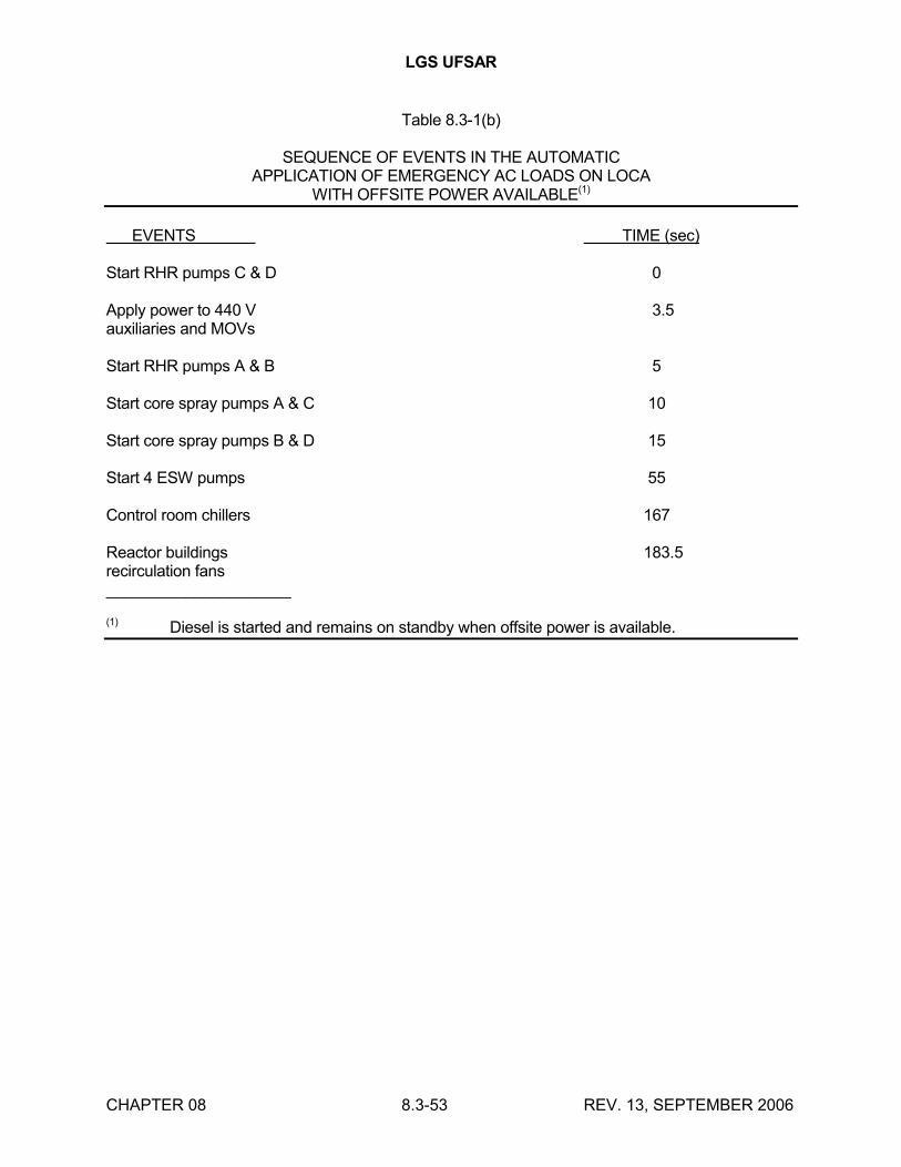
LGS UFSAR
CHAPTER 08 8.3-53 REV. 13, SEPTEMBER 2006
Table 8.3-1(b)
SEQUENCE OF EVENTS IN THE AUTOMATICAPPLICATION OF EMERGENCY AC LOADS ON LOCA
WITH OFFSITE POWER AVAILABLE(1)
EVENTS TIME (sec)
Start RHR pumps C & D 0
Apply power to 440 V 3.5auxiliaries and MOVs
Start RHR pumps A & B 5
Start core spray pumps A & C 10
Start core spray pumps B & D 15
Start 4 ESW pumps 55
Control room chillers 167
Reactor buildings 183.5recirculation fans_____________________
(1) Diesel is started and remains on standby when offsite power is available.

LGS UFSAR
CHAPTER 08 8.3-54 REV. 15 SEPTEMBER 2010
TABLE 8.3-2 (Page 1 of 2)SUMMARY OF LOADING
DIESEL GENERATOR AND EMERGENCY BUSESSAFEGUARD AND SELECTED NON-SAFEGUARD LOADS
MAXIMUM LOADINGOF ANY ONE DIESEL
GENERATOR (kW)
TABLE 0 - 10 10 MIN - 1 HOUR andNO. DESCRIPTION MIN 1 HOUR LONGER
8.3 - 3 Assignment of safeguard and -- -- --selected non-safeguard loadsto diesel generators andemergency busesBoth units in operationUnit 1 DBA; Unit 2 spurious
LOCA
8.3 - 9 All D/G in service 2394 1910 19108.3 - 10 D11 D/G out-of -service 2397 2165 21658.3 - 11 D12 D/G out-of-service 2394 2222 22228.3 - 12 D13 D/G out-of-service 2394 1910 19108.3 - 13 D14 D/G out-of-service 2394 2190 21908.3 - 14 D21 D/G out-of-service 2394 2062 20628.3 - 15 D22 D/G out-of-service 2394 1846 18468.3 - 16 D23 D/G out-of-service 2394 2048 20488.3 - 17 D24 D/G out-of-service 2394 1824 1824
The above loadings are based on the minimum required engineeredsafeguard and selected non-safeguard laods for the following situation:
* Unit 1 DBA with a spurious LOCA in Unit 2 for the 0 -10 minute period following by an emergency shutdown of Unit 2.
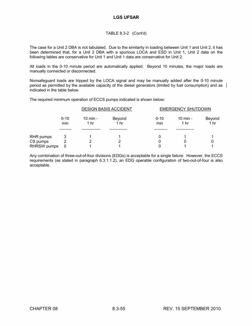
LGS UFSAR
CHAPTER 08 8.3-55 REV. 15 SEPTEMBER 2010
TABLE 8.3-2 (Cont'd)
The case for a Unit 2 DBA is not tabulated. Due to the similarity in loading between Unit 1 and Unit 2, it has been determined that, for a Unit 2 DBA with a spurious LOCA and ESD in Unit 1, Unit 2 data on the following tables are conservative for Unit 1 and Unit 1 data are conservative for Unit 2.
All loads in the 0-10 minute period are automatically applied. Beyond 10 minutes, the major loads are manually connected or disconnected.
Nonsafeguard loads are tripped by the LOCA signal and may be manually added after the 0-10 minute period as permitted by the available capacity of the diesel generators (limited by fuel consumption) and as indicated in the table below.
The required minimum operation of ECCS pumps indicated is shown below:
DESIGN BASIS ACCIDENT EMERGENCY SHUTDOWN
0-10 10 min - Beyond 0-10 10 min - Beyondmin 1 hr 1 hr min 1 hr 1 hr
RHR pumps 3 1 1 0 1 1CS pumps 2 2 2 0 0 0RHRSW pumps 0 1 1 0 1 1
Any combination of three-out-of-four divisions (EDGs) is acceptable for a single failure. However, the ECCS requirements (as stated in paragraph 6.3.1.1.2), an EDG operable configuration of two-out-of-four is also acceptable.

LGS UFSAR
CHAPTER 08 8.3-56 REV. 15, SEPTEMBER 2010
TABLE 8.3 – 3 (PAGE 1 OF 6)
ASSIGNMENT OF SAFEGUARD AND SELECTED NON-SAFEGUARD LOADS
TO DIESEL GENERATORS AND EMERGENCY BUSES
STARTUP MODE & OPERATING
NUMBER OF OPERATING UNITS UNIT 1 or UNIT 2
UNIT 1 or UNIT 2 DBA EMERGENCY SHUTDOWN (2)
EQUIP CAPACITY RATED HP OPER KW STANDBY STANDBY
ITEM LOAD DESCRIPTION COMMENTS NO. UNIT 1 COMMON UNIT 2 EACH EACH EACH AUTO AUTO MAN MAN AUTO AUTO MAN MAN
01 RHR PUMP (9) P202 4 0 4 1/3 1250 993 4 0 0 0 0 0 3 1
02 CORE SPRAY PUMP P206 4 0 4 1/2 600 529 4 0 0 0 0 0 0 0
03 RHR SERVICE WATER PUMP * P506 0 4 0 F 700 519 0 0 0 2 0 0 0 2
04 ESW PUMP * P548 0 4 0 1/2 500 389 4 0 0 0 4 0 0 0
05 125V BATTERY CHARGER D103 4 & 2 0 4 & 2 1/6 0 25 & 9 6 0 0 0 6 0 0 0
06 DRYWELL COOLER FAN V212 16 0 16 1/8 30 20 8 8 0 0 8 8 0 0
07 DG ROOM VENT FAN V512 8 0 8 1/2 20 15 4 4 0 0 4 4 0 0
08 RHR ROOM COOLING UNIT V210 8 0 8 1/2 20 16 4 4 0 0 4 4 0 0
09 CORE SPRAY ROOM COOLING UNIT V211 8 0 8 F 10 7 & 8 4 4 0 0 4 4 0 0
10 HPCI ROOM COOLING UNIT V209 2 0 2 F 15 10 1 1 0 0 1 1 0 0
11 RCIC ROOM COOLING UNIT V208 2 0 2 F 5 4 1 1 0 0 1 1 0 0
12 INSTRUMENT AC POWER SUPPLY Y101 4 0 4 1/4 0 11 & 12 4 0 0 0 4 0 0 0
12 INSTRUMENT AC POWER SUPPLY Y102 0 0 0 0 0 0 0 0 0 0 0 0 0 0
12 INSTRUMENT AC POWER SUPPLY Y103 0 0 0 0 0 0 0 0 0 0 0 0 0 0
12 INSTRUMENT AC POWER SUPPLY Y104 0 0 0 0 0 0 0 0 0 0 0 0 0 0
13 DG START AIR COMPRESSOR o K513 8 0 8 F 20 7 0 0 4 4 4 4 0 0
14 DG FUEL OIL TRANSFER PUMP P514 4 0 4 F 1-1/2 1 0 0 0 4 0 0 0 4
15 SGTS HEATER * E188 0 2 0 F 0 44 2 0 0 0 2 0 0 0
16 SGTS ROOM UNIT COOLER * V140 0 2 0 F 1 1 1 1 0 0 1 1 0 0
17 SGTS ROOM ACCESS UNIT COOLER * V141 0 2 0 F 7-1/2 6 1 1 0 0 1 1 0 0
18 SGTS EXHAUST FAN * V163 0 2 0 F 40 32 1 0 0 0 1 0 0 0
19 RERS FAN V213 2 0 2 F 200 151 1 1 0 0 1 1 0 0
20 HVAC DAMPER POWER Y206 4 0 4 1/4 0 0 4 0 0 0 4 0 0 0
20 HVAC DAMPER POWER Y207 0 0 0 0 0 0 0 0 0 0 0 0 0 0
20 HVAC DAMPER POWER Y163 0 0 0 0 0 0 0 0 0 0 0 0 0 0
20 HVAC DAMPER POWER Y164 0 0 0 0 0 0 0 0 0 0 0 0 0 0
21 CONTROL ROOM CHILLER * K112 0 2 0 F 0 329/330 1 1 0 0 1 1 0 0
22 CONTROL ROOM CHILLER WATER PP * P162 0 2 0 F 25 16 1 1 0 0 1 1 0 0
23 AUX PNL & COMP RM FAN COIL UNIT * V114 0 2 0 F 38.5 24 1 1 0 0 1 1 0 0
24 AUX PNL & COMP RM RETURN AIR UNIT * V120 0 2 0 F 20 16 1 1 0 0 1 1 0 0
25 CONTROL ROOM AIR COND UNIT * V116 0 2 0 F 40 32 1 1 0 0 1 1 0 0
26 CONTROL ROOM RETURN AIR FAN * V121 0 2 0 F 15 12 1 1 0 0 1 1 0 0
27 EMER SWGR & BTRY RM AIR COND UNIT * V118 0 2 0 F 15 9 1 1 0 0 1 1 0 0
28 AUX EQUIP & COMP RM AREA HTR * ++ E193 0 2 0 F 0 52 0 0 0 0 1 1 0 0
29 CONTROL ROOM AREA HEATER * ++ E192 0 2 0 F 0 40 0 0 0 0 1 1 0 0
30 CONT RM FRESH AIR INTAKE HTR * E191 0 2 0 F 0 32 0 0 0 0 0 0 0 0
31 SPRAY POND STATION HTG COIL FAN * V543 0 4 0 1/2 10 7 2 2 0 0 2 2 0 0
32 SLCS HEATERS ++ S213 1 & 1 0 1 & 1 F 0 8 1 0 0 1 1 0 0 1
33 CONTAINMENT H2 RECOMBINER S403 2 0 2 F 0 48 0 0 1 1 0 0 1 1
34 CONT'L RM EMER FRESH AIR SPLY FAN * V127 0 2 0 F 10 6 1 1 0 0 1 1 0 0
35 CONTROL ROOM CHILLER OIL PUMP * P168 0 2 0 F 1-1/2 1 1 1 0 0 1 1 0 0
36 DG AUXILIARIES o G501 4 0 4 F 35KVA 14 4 0 0 0 4 0 0 0
37 DELETED

LGS UFSAR
CHAPTER 08 8.3-57 REV. 15, SEPTEMBER 2010
TABLE 8.3 – 3 (Cont’d) (PAGE 2 OF 6)
ASSIGNMENT OF SAFEGUARD AND SELECTED NON- SAFEGUARD LOADS
TO DIESEL GENERATORS AND EMERGENCY BUSES
STARTUP MODE & OPERATING
NUMBER OF OPERATING UNITS UNIT 1 or UNIT 2
UNIT 1 or UNIT 2 DBA EMERGENCY SHUTDOWN (2)
EQUIP CAPACITY RATED HP OPER KW STANDBY STANDBY
ITEM LOAD DESCRIPTION COMMENTS NO. UNIT 1 COMMON UNIT 2 EACH EACH EACH AUTO AUTO MAN MAN AUTO AUTO MAN MAN
37 DELETED
38 DELETED
39 CRD PUMP o P158 2 0 2 F 250 133 0 0 0 0 0 0 1 1
40 DELETED
41 RECW PUMP ++ P210 2 0 2 F 100 68 0 0 1 1 1 1 0 0
42 TECW o P103 2 0 2 F 15 11 & 12 0 0 1 1 1 1 1 0
43 INSTRUMENT AC POWER SUPPLY o Y105 4 0 4 1/4 0 0 0 0 0 4 4 0 0 0
43 INSTRUMENT AC POWER SUPPLY o Y106 0 0 0 0 0 0 0 0 0 0 0 0 0 0
43 INSTRUMENT AC POWER SUPPLY o Y201 0 0 0 0 0 0 0 0 0 0 0 0 0 0
43 INSTRUMENT AC POWER SUPPLY o Y202 0 0 0 0 0 0 0 0 0 0 0 0 0 0
44 EMERGENCY LIGHTING o ! MISC 7 6 7 0 0 0 0 0 0 13 0 0 0 13
45 TURBINE GEN BEARING LIFT PUMP o P109 9 0 9 1/9 5 36 & 45 (TOTAL) 0 0 0 9 9 0 0 0
46 TURBINE GEN TURNING OIL PP o P111 1 0 1 F 40 32 0 0 0 1 1 0 0 0
47 TURBINE GEN TURNING GEAR o S103 1 0 1 F 60 48 0 0 0 1 1 0 0 0
48 RFPT GEAR o S106 3 0 3 F 1-1/2 1 0 0 0 3 3 0 0 0
49 INSTRUMENT GAS COMPRESSOR o (12) K203 2 0 2 F 5 1 0 0 1 1 1 1 0 0
50 INSTRUMENT AIR COMPRESSOR o K101 2 0 2 F 100 33 0 0 1 1 1 1 0 0
51 DELETED
52 OSC XFMR PNLS OOL140 & OOL141 * X186 0 1 0 0 30 24 0 0 0 1 0 0 0 1
53 TEST ENGINEER'S WORKSHOP * X187 0 1 0 0 30 12 0 0 0 1 0 0 0 1
54 NORTH STACK RM ANTENNA SYS XFMR * X595 0 1 0 0 15 9 0 0 0 1 0 0 0 1
55 DELETED
56 CRD REPAIR RM COOLING FAN V904 0 1 1 0 0 0 0 0 0 0 0 0 0 0
57 125V BATTERY CHARGER o D113 2 0 2 1/2 0 96 0 0 0 2 2 0 0 0
58 FIRE ALARM & P/A * + 1X5 0 0 0 0 0 12 1 0 0 0 1 0 0 0
59 FUEL POOL COOLING WATER PUMP o P211 3 0 3 0 50 32 0 0 1 2 0 0 1 2
60 FUEL POOL SVC WTR BSTR PUMP (7) P212 3 0 3 0 25 19 0 0 0 0 0 0 0 0
61 INSTR. AC PWR SUPPLY (SPRAY POND) o Y501 0 4 0 1/4 0 1 0 0 0 0 2 2 0 0
62 SPRAY POND PP STATION HTG COIL ++ * E701 0 4 0 1/2 0 96 0 0 0 0 2 2 0 0
63 SGTS RM VENT EXHAUST FAN o *(13) V131 0 2 0 0 10 7 0 0 1 1 1 1 0 0
64 SECURITY AREAS AIR COND. (11) o* V565 0 2 0 0 17-1/2 14 0 0 1 1 0 0 0 1
65 PIPING FILL PUMP P256 2 0 2 0 5 3 0 0 0 2 0 0 0 0
66 DRYWELL H2O2 ANALYZER S205 1 0 1 0 1 1 0 0 0 1 0 0 0 1
67 SUPPRESSION POOL H2O2 ANALYZER S206 1 0 1 0 1 1 0 0 0 1 0 0 0 1
68 CHILLER PUMP-OUT COMPRESSOR o * K114 0 2 0 0 2 2 0 0 0 0 0 0 0 0
69 SPRAY POND SUMP PUMP o * P578 0 4 0 0 5 2 0 0 4 0 0 4 0 0
70 AUX EG. RM & COMP RM ELEC HUMIDFR o * E743 0 2 0 0 0 43 0 0 0 0 1 0 0 0
71 CONT RM ELEC HUMIDIFIER o * E744 0 2 0 0 0 29 0 0 0 0 1 0 0 0
72 250V BATTERY CHARGER o D123 1 0 1 0 0 9 0 0 0 1 1 0 0 0
73 ALT. POWER SUPPLY TO 10X161 XFMR o 10X161 1 0 0 0 37-1/2 30 0 0 0 0 0 0 0 0
74 STATIC INVERTER 00-D592 XFMR o * 00-X592 0 1 0 0 37-1/2 30 0 0 0 0 0 0 0 0
75 TELEPHONE EQUIP POWER XFMR o * X503 0 1 0 0 7-1/2 6 0 0 0 1 1 0 0 0
76 RECOMBINER HYDROGEN ANALYZER o P947 3 0 3 0 1 1 0 0 0 0 0 0 0 0
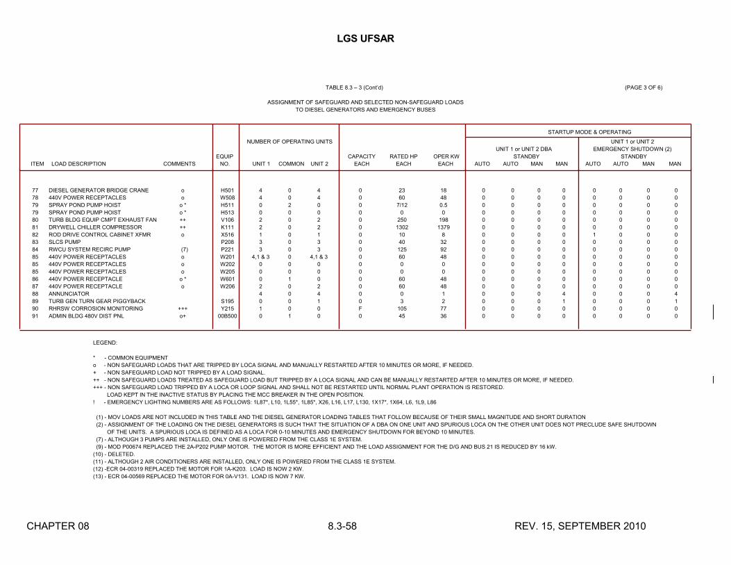
LGS UFSAR
CHAPTER 08 8.3-58 REV. 15, SEPTEMBER 2010
TABLE 8.3 – 3 (Cont’d) (PAGE 3 OF 6)
ASSIGNMENT OF SAFEGUARD AND SELECTED NON-SAFEGUARD LOADS
TO DIESEL GENERATORS AND EMERGENCY BUSES
STARTUP MODE & OPERATING
NUMBER OF OPERATING UNITS UNIT 1 or UNIT 2
UNIT 1 or UNIT 2 DBA EMERGENCY SHUTDOWN (2)
EQUIP CAPACITY RATED HP OPER KW STANDBY STANDBY
ITEM LOAD DESCRIPTION COMMENTS NO. UNIT 1 COMMON UNIT 2 EACH EACH EACH AUTO AUTO MAN MAN AUTO AUTO MAN MAN
77 DIESEL GENERATOR BRIDGE CRANE o H501 4 0 4 0 23 18 0 0 0 0 0 0 0 0
78 440V POWER RECEPTACLES o W508 4 0 4 0 60 48 0 0 0 0 0 0 0 0
79 SPRAY POND PUMP HOIST o * H511 0 2 0 0 7/12 0.5 0 0 0 0 0 0 0 0
79 SPRAY POND PUMP HOIST o * H513 0 0 0 0 0 0 0 0 0 0 0 0 0 0
80 TURB BLDG EQUIP CMPT EXHAUST FAN ++ V106 2 0 2 0 250 198 0 0 0 0 0 0 0 0
81 DRYWELL CHILLER COMPRESSOR ++ K111 2 0 2 0 1302 1379 0 0 0 0 0 0 0 0
82 ROD DRIVE CONTROL CABINET XFMR o X516 1 0 1 0 10 8 0 0 0 0 1 0 0 0
83 SLCS PUMP P208 3 0 3 0 40 32 0 0 0 0 0 0 0 0
84 RWCU SYSTEM RECIRC PUMP (7) P221 3 0 3 0 125 92 0 0 0 0 0 0 0 0
85 440V POWER RECEPTACLES o W201 4,1 & 3 0 4,1 & 3 0 60 48 0 0 0 0 0 0 0 0
85 440V POWER RECEPTACLES o W202 0 0 0 0 0 0 0 0 0 0 0 0 0 0
85 440V POWER RECEPTACLES o W205 0 0 0 0 0 0 0 0 0 0 0 0 0 0
86 440V POWER RECEPTACLE o * W601 0 1 0 0 60 48 0 0 0 0 0 0 0 0
87 440V POWER RECEPTACLE o W206 2 0 2 0 60 48 0 0 0 0 0 0 0 0
88 ANNUNCIATOR 4 0 4 0 0 1 0 0 0 4 0 0 0 4
89 TURB GEN TURN GEAR PIGGYBACK S195 0 0 1 0 3 2 0 0 0 1 0 0 0 1
90 RHRSW CORROSION MONITORING +++ Y215 1 0 0 F 105 77 0 0 0 0 0 0 0 0
91 ADMIN BLDG 480V DIST PNL o+ 00B500 0 1 0 0 45 36 0 0 0 0 0 0 0 0
LEGEND:
* - COMMON EQUIPMENT
o - NON SAFEGUARD LOADS THAT ARE TRIPPED BY LOCA SIGNAL AND MANUALLY RESTARTED AFTER 10 MINUTES OR MORE, IF NEEDED.
+ - NON SAFEGUARD LOAD NOT TRIPPED BY A LOAD SIGNAL.
++ - NON SAFEGUARD LOADS TREATED AS SAFEGUARD LOAD BUT TRIPPED BY A LOCA SIGNAL AND CAN BE MANUALLY RESTARTED AFTER 10 MINUTES OR MORE, IF NEEDED.
+++ - NON SAFEGUARD LOAD TRIPPED BY A LOCA OR LOOP SIGNAL AND SHALL NOT BE RESTARTED UNTIL NORMAL PLANT OPERATION IS RESTORED.
LOAD KEPT IN THE INACTIVE STATUS BY PLACING THE MCC BREAKER IN THE OPEN POSITION.
! - EMERGENCY LIGHTING NUMBERS ARE AS FOLLOWS: 1L87*, L10, 1L55*, 1L85*, X26, L16, L17, L130, 1X17*, 1X64, L6, 1L9, L86
(1) - MOV LOADS ARE NOT INCLUDED IN THIS TABLE AND THE DIESEL GENERATOR LOADING TABLES THAT FOLLOW BECAUSE OF THEIR SMALL MAGNITUDE AND SHORT DURATION
(2) - ASSIGNMENT OF THE LOADING ON THE DIESEL GENERATORS IS SUCH THAT THE SITUATION OF A DBA ON ONE UNIT AND SPURIOUS LOCA ON THE OTHER UNIT DOES NOT PRECLUDE SAFE SHUTDOWN
OF THE UNITS. A SPURIOUS LOCA IS DEFINED AS A LOCA FOR 0-10 MINUTES AND EMERGENCY SHUTDOWN FOR BEYOND 10 MINUTES.
(7) - ALTHOUGH 3 PUMPS ARE INSTALLED, ONLY ONE IS POWERED FROM THE CLASS 1E SYSTEM.
(9) - MOD P00674 REPLACED THE 2A-P202 PUMP MOTOR. THE MOTOR IS MORE EFFICIENT AND THE LOAD ASSIGNMENT FOR THE D/G AND BUS 21 IS REDUCED BY 16 kW.
(10) - DELETED.
(11) - ALTHOUGH 2 AIR CONDITIONERS ARE INSTALLED, ONLY ONE IS POWERED FROM THE CLASS 1E SYSTEM.
(12) -ECR 04-00319 REPLACED THE MOTOR FOR 1A-K203. LOAD IS NOW 2 KW.
(13) - ECR 04-00569 REPLACED THE MOTOR FOR 0A-V131. LOAD IS NOW 7 KW.

LGS UFSAR
CHAPTER 08 8.3-59 REV. 15, SEPTEMBER 2010
TABLE 8.3 – 3 (Cont’d) (PAGE 4 OF 6)
ASSIGNMENT OF SAFEGUARD AND SELECTED NON-SAFEGUARD LOADS
TO DIESEL GENERATORS AND EMERGENCY BUSES
ASSIGNMENT OF LOADS TO DIESEL GENERATORS AND EMERGENCY BUSES (IN kw)
UNIT 1 UNIT 2
NUMBER OF OPERATING UNITS (UNIT 1 and UNIT 2 IN OPERATION) (UNIT 1 and UNIT 2 IN OPERATION)
D/G D/G D/G D/G D/G D/G D/G D/G
EQUIP BUS BUS BUS BUS BUS BUS BUS BUS
ITEM LOAD DESCRIPTION COMMENTS NO. UNIT 1 COMMON UNIT 2 D11 D12 D13 D14 D21 D22 D23 D24
01 RHR PUMP (9) P202 4 0 4 993 993 993 993 977 993 993 993
02 CORE SPRAY PUMP P206 4 0 4 529 529 529 529 529 529 529 529
03 RHR SERVICE WATER PUMP * P506 0 4 0 519 519 0 0 519 519 0 0
04 ESW PUMP * P548 0 4 0 389 389 0 0 0 0 389 389
05 125V BATTERY CHARGER D103 4 & 2 0 4 & 2 51 50 9 9 51 51 9 9
06 DRYWELL COOLER FAN V212 16 0 16 80 80 80 80 80 80 80 80
07 DG ROOM VENT FAN V512 8 0 8 30 30 30 30 30 30 30 30
08 RHR ROOM COOLING UNIT V210 8 0 8 32 32 32 32 32 32 32 32
09 CORE SPRAY ROOM COOLING UNIT V211 8 0 8 14 16 14 16 14 14 14 14
10 HPCI ROOM COOLING UNIT V209 2 0 2 0 20 0 0 0 20 0 0
11 RCIC ROOM COOLING UNIT V208 2 0 2 8 0 0 0 8 0 0 0
12 INSTRUMENT AC POWER SUPPLY Y101 4 0 4 11 11 12 11 12 12 12 12
12 INSTRUMENT AC POWER SUPPLY Y102 0 0 0 0 0 0 0 0 0 0 0
12 INSTRUMENT AC POWER SUPPLY Y103 0 0 0 0 0 0 0 0 0 0 0
12 INSTRUMENT AC POWER SUPPLY Y104 0 0 0 0 0 0 0 0 0 0 0
13 DG START AIR COMPRESSOR o K513 8 0 8 14 14 14 14 14 14 14 14
14 DG FUEL OIL TRANSFER PUMP P514 4 0 4 1 1 1 1 1 1 1 1
15 SGTS HEATER * E188 0 2 0 44 44 0 0 0 0 0 0
16 SGTS ROOM UNIT COOLER * V140 0 2 0 1 1 0 0 0 0 0 0
17 SGTS ROOM ACCESS UNIT COOLER * V141 0 2 0 6 6 0 0 0 0 0 0
18 SGTS EXHAUST FAN * V163 0 2 0 32 32 0 0 0 0 0 0
19 RERS FAN V213 2 0 2 151 151 0 0 151 151 0 0
20 HVAC DAMPER POWER Y206 4 0 4 4 4 16 20 2 2 0 0
20 HVAC DAMPER POWER Y207 0 0 0 0 0 0 0 0 0 0 0
20 HVAC DAMPER POWER Y163 0 0 0 0 0 0 0 0 0 0 0
20 HVAC DAMPER POWER Y164 0 0 0 0 0 0 0 0 0 0 0
21 CONTROL ROOM CHILLER * K112 0 2 0 0 0 329/330 330 0 0 0 0
22 CONTROL ROOM CHILLER WATER PP * P162 0 2 0 0 0 16 16 0 0 0 0
23 AUX PNL & COMP RM FAN COIL UNIT * V114 0 2 0 0 0 24 24 0 0 0 0
24 AUX PNL & COMP RM RETURN AIR UNIT * V120 0 2 0 0 0 16 16 0 0 0 0
25 CONTROL ROOM AIR COND UNIT * V116 0 2 0 0 0 32 32 0 0 0 0
26 CONTROL ROOM RETURN AIR FAN * V121 0 2 0 0 0 12 12 0 0 0 0
27 EMER SWGR & BTRY RM AIR COND UNIT * V118 0 2 0 0 0 9 9 0 0 0 0
28 AUX EQUIP & COMP RM AREA HTR * ++ E193 0 2 0 0 0 52 52 0 0 0 0
29 CONTROL ROOM AREA HEATER * ++ E192 0 2 0 0 0 40 40 0 0 0 0
30 CONT RM FRESH AIR INTAKE HTR * E191 0 2 0 0 0 32 32 0 0 0 0
31 SPRAY POND STATION HTG COIL FAN * V543 0 4 0 7 7 0 0 0 0 7 7
32 SLCS HEATERS ++ S213 1 & 1 0 1 & 1 0 0 8 8 0 0 8 8
33 CONTAINMENT H2 RECOMBINER S403 2 0 2 0 0 48 48 0 0 48 48
34 CONT'L RM EMER FRESH AIR SPLY FAN * V127 0 2 0 0 0 6 6 0 0 0 0
35 CONTROL ROOM CHILLER OIL PUMP * P168 0 2 0 0 0 1 1 0 0 0 0
36 DG AUXILIARIES o G501 4 0 4 14 14 14 14 14 14 14 14
37 DELETED

LGS UFSAR
CHAPTER 08 8.3-60 REV. 15, SEPTEMBER 2010
(PAGE 5 OF 6)
TABLE 8.3 – 3 (Cont’d)
ASSIGNMENT OF SAFEGUARD AND SELECTED NON-SAFEGUARD LOADS
TO DIESEL GENERATORS AND EMERGENCY BUSES
ASSIGNMENT OF LOADS TO DIESEL GENERATORS AND EMERGENCY BUSES (IN kw)
UNIT 1 UNIT 2
NUMBER OF OPERATING UNITS (UNIT 1 and UNIT 2 IN OPERATION) (UNIT 1 and UNIT 2 IN OPERATION)
D/G D/G D/G D/G D/G D/G D/G D/G
EQUIP BUS BUS BUS BUS BUS BUS BUS BUS
ITEM LOAD DESCRIPTION COMMENTS NO. UNIT 1 COMMON UNIT 2 D11 D12 D13 D14 D21 D22 D23 D24
37 DELETED
38 DELETED
39 CRD PUMP o P158 2 0 2 0 0 133 133 0 0 133 133
40 DELETED
41 RECW PUMP ++ P210 2 0 2 0 0 68 68 0 0 68 68
42 TECW PUMP o P103 2 0 2 11 11 0 0 12 11 0 0
43 INSTRUMENT AC POWER SUPPLY o Y105 4 0 4 5 10 24 14 24 24 24 24
43 INSTRUMENT AC POWER SUPPLY o Y106 0 0 0 0 0 0 0 0 0 0 0
43 INSTRUMENT AC POWER SUPPLY o Y201 0 0 0 0 0 0 0 0 0 0 0
43 INSTRUMENT AC POWER SUPPLY o Y202 0 0 0 0 0 0 0 0 0 0 0
44 EMERGENCY LIGHTING o ! MISC 7 6 7 11 70 109 99 0 59 80 68
45 TURBINE GEN BEARING LIFT PUMP o P109 9 0 9 45 0 0 0 36 0 0 0
46 TURBINE GEN TURNING OIL PP o P111 1 0 1 32 0 0 0 32 0 0 0
47 TURBINE GEN TURNING GEAR o S103 1 0 1 48 0 0 0 24 0 0 0
48 RFPT GEAR o S106 3 0 3 2 1 0 0 2 1 0 0
49 INSTRUMENT GAS COMPRESSOR o (12) K203 2 0 2 1 1 0 0 1 1 0 0
50 INSTRUMENT AIR COMPRESSOR o K101 2 0 2 0 0 33 33 0 0 33 33
51 DELETED
52 OSC XFMR PNLS OOL140 & OOL141 * X186 0 1 0 0 24 0 0 0 0 0 0
53 TEST ENGINEER'S WORKSHOP * X187 0 1 0 0 12 0 0 0 0 0 0
54 NORTH STACK RM ANTENNA SYS XFMR * X595 0 1 0 0 9 0 0 0 0 0 0
55 DELETED
56 CRD REPAIR RM COOLING FAN V904 0 1 1 0 0 0 0 0 0 0 0
57 125V BATTERY CHARGER o D113 2 0 2 0 0 0 96 0 0 0 96
58 FIRE ALARM & P/A * + 1X5 0 0 0 0 0 0 12 0 0 0 0
59 FUEL POOL COOLING WATER PUMP o P211 3 0 3 32 32 0 32 32 32 0 32
60 FUEL POOL SVC WTR BSTR PUMP (7) P212 3 0 3 19 0 0 0 19 0 0 0
61 INSTR. AC PWR SUPPLY (SPRAY POND) o Y501 0 4 0 1 1 0 0 0 0 8 8
62 SPRAY POND PP STATION HTG COIL ++ * E701 0 4 0 96 96 0 0 0 0 96 96
63 SGTS RM VENT EXHAUST FAN o *(13) V131 0 2 0 7 7 0 0 0 0 0 0
64 SECURITY AREAS AIR COND. (11) o * V565 0 2 0 0 0 14 0 0 0 0 0
65 PIPING FILL PUMP P256 2 0 2 3 3 0 0 3 3 0 0
66 DRYWELL H2O2 ANALYZER S205 1 0 1 0 0 0 1 0 0 0 1
67 SUPPRESSION POOL H2O2 ANALYZER S206 1 0 1 0 0 1 0 0 0 1 0
68 CHILLER PUMP-OUT COMPRESSOR o * K114 0 2 0 0 0 2 2 0 0 0 0
69 SPRAY POND SUMP PUMP o * P578 0 4 0 2 2 0 0 0 0 2 2
70 AUX EG. RM & COMP RM ELEC HUMIDFR o * E743 0 2 0 43 43 0 0 0 0 0 0
71 CONT RM ELEC HUMIDIFIER o * E744 0 2 0 29 29 0 0 0 0 0 0
72 250V BATTERY CHARGER o D123 1 0 1 0 9 0 0 0 9 0 0
73 ALT. POWER SUPPLY TO 10X161 XFMR o 10X161 1 0 0 30 0 0 0 0 0 0 0
74 STATIC INVERTER 00-D592 XFMR o * 00-X592 0 1 0 0 0 0 0 30 0 0 0
75 TELEPHONE EQUIP POWER XFMR o * X503 0 1 0 6 0 0 0 0 0 0 0
76 RECOMBINER HYDROGEN ANALYZER o P947 3 0 3 1 2 0 0 1 2 0 0

LGS UFSAR
CHAPTER 08 8.3-61 REV. 15, SEPTEMBER 2010
TABLE 8.3 – 3 (Cont’d) (PAGE 6 OF 6)
ASSIGNMENT OF SAFEGUARD AND SELECTED NON-SAFEGUARD LOADS
TO DIESEL GENERATORS AND EMERGENCY BUSES
ASSIGNMENT OF LOADS TO DIESEL GENERATORS AND EMERGENCY BUSES (IN kw)
UNIT 1 UNIT 2
NUMBER OF OPERATING UNITS (UNIT 1 and UNIT 2 IN OPERATION) (UNIT 1 and UNIT 2 IN OPERATION)
D/G D/G D/G D/G D/G D/G D/G D/G
EQUIP BUS BUS BUS BUS BUS BUS BUS BUS
ITEM LOAD DESCRIPTION COMMENTS NO. UNIT 1 COMMON UNIT 2 D11 D12 D13 D14 D21 D22 D23 D24
77 DIESEL GENERATOR BRIDGE CRANE o H501 4 0 4 18 18 18 18 18 18 18 18
78 440V POWER RECEPTACLES o W508 4 0 4 48 48 48 48 48 48 48 48
79 SPRAY POND PUMP HOIST o * H511 0 2 0 0.5 0 0 0 0 0 0 0.5
79 SPRAY POND PUMP HOIST o * H513 0 0 0 0 0 0 0 0 0 0 0
80 TURB BLDG EQUIP CMPT EXHAUST FAN ++ V106 2 0 2 197 198 0 0 198 198 0 0
81 DRYWELL CHILLER COMPRESSOR ++ K111 2 0 2 0 0 1379 1379 0 0 1379 1379
82 ROD DRIVE CONTROL CABINET XFMR o X516 1 0 1 0 8 0 0 0 8 0 0
83 SLCS PUMP P208 3 0 3 32 32 32 0 32 32 32 0
84 RWCU SYSTEM RECIRC PUMP (7) P221 3 0 3 0 0 92 0 0 0 92 0
85 440V POWER RECEPTACLES o W201 4,1 & 3 0 4,1 & 3 0 0 0 144 0 0 0 144
85 440V POWER RECEPTACLES o W202 0 0 0 0 0 0 0 0 0 0 0
85 440V POWER RECEPTACLES o W205 0 0 0 0 0 0 0 0 0 0 0
86 440V POWER RECEPTACLE/SP RECIRC o * W601 0 1 0 0 0 0 0 0 0 0 48
87 440V POWER RECEPTACLE o W206 2 0 2 0 48 0 0 0 48 0 0
88 ANNUNCIATOR 4 0 4 1 1 1 1 1 1 1 1
89 TURB GEN TURN GEAR PIGGYBACK S195 0 0 1 0 0 0 0 2 0 0 0
90 RHRSW CORROSION MONITORING +++ Y215 1 0 0 0 77 0 0 0 0 0 0
91 ADMIN BLDG 480V DISTR PNL o+ 00B500 0 1 0 0 0 36 0 0 0 0 0
LEGEND:
* - COMMON EQUIPMENT
o - NON SAFEGUARD LOADS THAT ARE TRIPPED BY LOCA SIGNAL AND MANUALLY RESTARTED AFTER 10 MINUTES OR MORE, IF NEEDED.
+ - NON SAFEGUARD LOAD NOT TRIPPED BY A LOAD SIGNAL.
++ - NON SAFEGUARD LOADS TREATED AS SAFEGUARD LOAD BUT TRIPPED BY A LOCA SIGNAL AND CAN BE MANUALLY RESTARTED AFTER 10 MINUTES OR MORE, IF
+++ - NON SAFEGUARD LOAD TRIPPED BY A LOCA OR LOOP SIGNAL AND SHALL NOT BE RESTARTED UNTIL NORMAL PLANT OPERATION IS RESTORED.
LOAD KEPT IN THE INACTIVE STATUS BY PLACING THE MCC BREAKER IN THE OPEN POSITION.
! - EMERGENCY LIGHTING NUMBERS ARE AS FOLLOWS: 1L87*, L10, 1L55*, 1L85*, X26, L16, L17, L130, 1X17*, 1X64, L6, 1L9*, L86
(1) - MOV LOADS ARE NOT INCLUDED IN THIS TABLE AND THE DIESEL GENERATOR LOADING TABLES THAT FOLLOW BECAUSE OF THEIR SMALL MAGNITUDE AND SHORT DURATION
(2) - ASSIGNMENT OF THE LOADING ON THE DIESEL GENERATORS IS SUCH THAT THE SITUATION OF A DBA ON ONE UNIT AND SPURIOUS LOCA ON THE OTHER UNIT DOES NOT PRECLUDE SAFE SHUTDOWN
OF THE UNITS. A SPURIOUS LOCA IS DEFINED AS A LOCA FOR 0-10 MINUTES AND EMERGENCY SHUTDOWN FOR BEYOND 10 MINUTES.
(7) - ALTHOUGH 3 PUMPS ARE INSTALLED, ONLY ONE IS POWERED FROM THE CLASS 1E SYSTEM.
(9) - MOD P00674 REPLACED THE 2A-P202 PUMP MOTOR. THE MOTOR IS MORE EFFICIENT AND THE LOAD ASSIGNMENT FOR THE D/G AND BUS 21 IS REDUCED BY 16 kW.
(10) - DELETED.
(11) - ALTHOUGH 2 AIR CONDITIONERS ARE INSTALLED, ONLY ONE IS POWERED FROM THE CLASS 1E SYSTEM.
(12)—ECR 04-00319 REPLACED THE MOTOR FOR 1A-K203. LOAD IS NOW 2 KW.
(13)—ECR 04-00569 REPLACED THE MOTOR FOR 0A-V131. LOAD IS NOW 7 KW.
LGS UFSAR
CHAPTER 08 8.3-62 REV. 14, SEPTEMBER 2008
Tables 8.3-4 through 8.3-8
Tables 8.3-4 through 8.3-8(Deleted)

LGS UFSAR
CHAPTER 08 8.3-63 REV. 15, SEPTEMBER 2010
Table 8.3-9
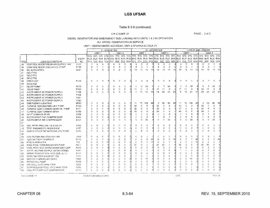
LGS UFSAR
CHAPTER 08 8.3-64 REV. 15, SEPTEMBER 2010
Table 8.3-9 (continued)

LGS UFSAR
CHAPTER 08 8.3-65 REV. 15, SEPTEMBER 2010
Table 8.3-9 (continued)

LGS UFSAR
CHAPTER 08 8.3-66 REV. 15, SEPTEMBER 2010
Table 8.3-10
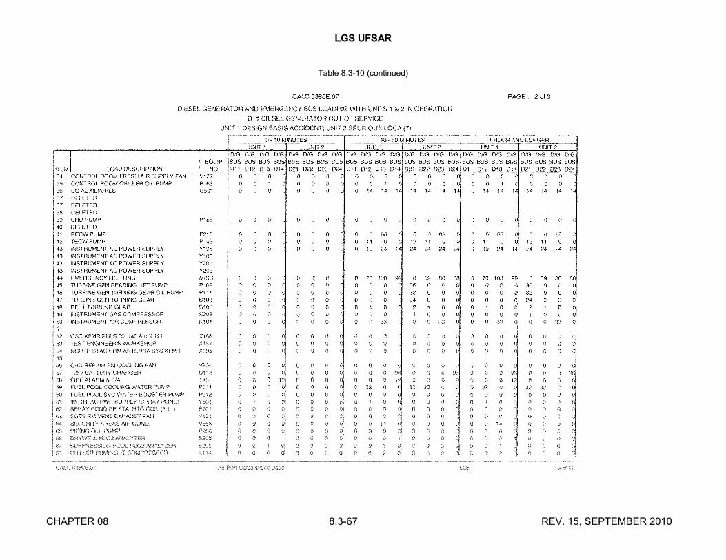
LGS UFSAR
CHAPTER 08 8.3-67 REV. 15, SEPTEMBER 2010
Table 8.3-10 (continued)
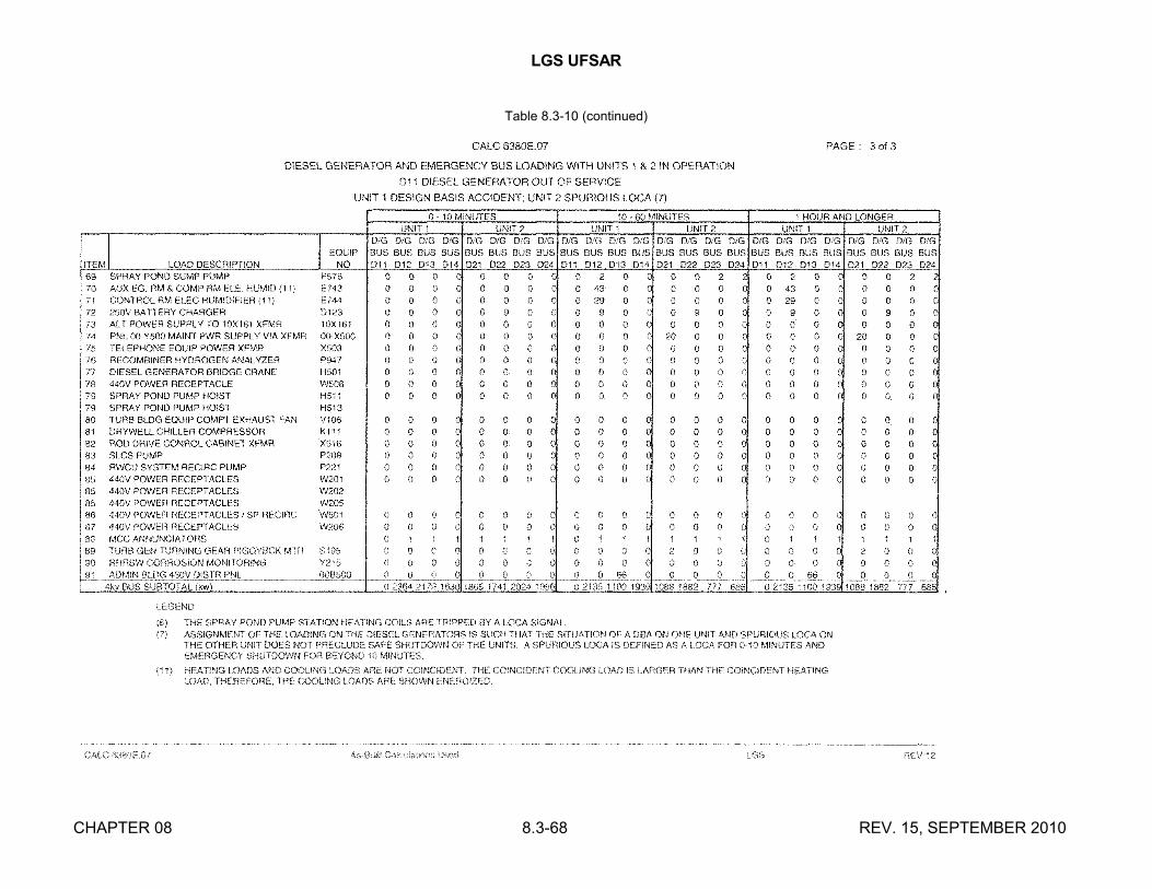
LGS UFSAR
CHAPTER 08 8.3-68 REV. 15, SEPTEMBER 2010
Table 8.3-10 (continued)

LGS UFSAR
CHAPTER 08 8.3-69 REV. 15, SEPTEMBER 2010
Table 8.3-11

LGS UFSAR
CHAPTER 08 8.3-70 REV. 15, SEPTEMBER 2010
Table 8.3-11 (continued)

LGS UFSAR
CHAPTER 08 8.3-71 REV. 15, SEPTEMBER 2010
Table 8.3-11 (continued)
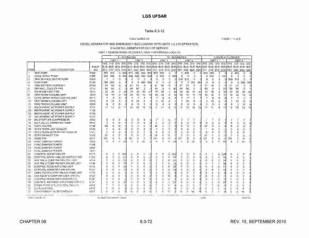
LGS UFSAR
CHAPTER 08 8.3-72 REV. 15, SEPTEMBER 2010
Table 8.3-12

LGS UFSAR
CHAPTER 08 8.3-73 REV. 15, SEPTEMBER 2010
Table 8.3-12 (continued)

LGS UFSAR
CHAPTER 08 8.3-74 REV. 15, SEPTEMBER 2010
Table 8.3-12 (continued)

LGS UFSAR
CHAPTER 08 8.3-75 REV. 15, SEPTEMBER 2010
Table 8.3-13

LGS UFSAR
CHAPTER 08 8.3-76 REV. 15, SEPTEMBER 2010
Table 8.3-13 (continued)
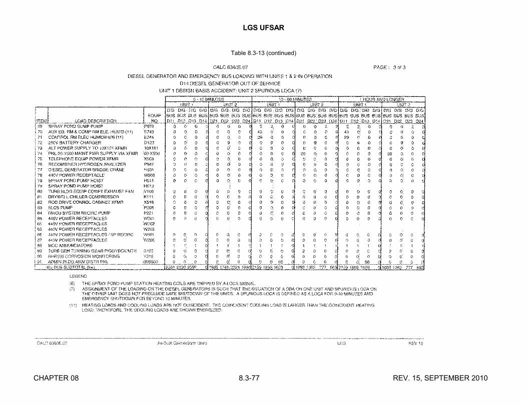
LGS UFSAR
CHAPTER 08 8.3-77 REV. 15, SEPTEMBER 2010
Table 8.3-13 (continued)

LGS UFSAR
CHAPTER 08 8.3-78 REV. 15, SEPTEMBER 2010
Table 8.3-14

LGS UFSAR
CHAPTER 08 8.3-79 REV. 15, SEPTEMBER 2010
Table 8.3-14 (continued)
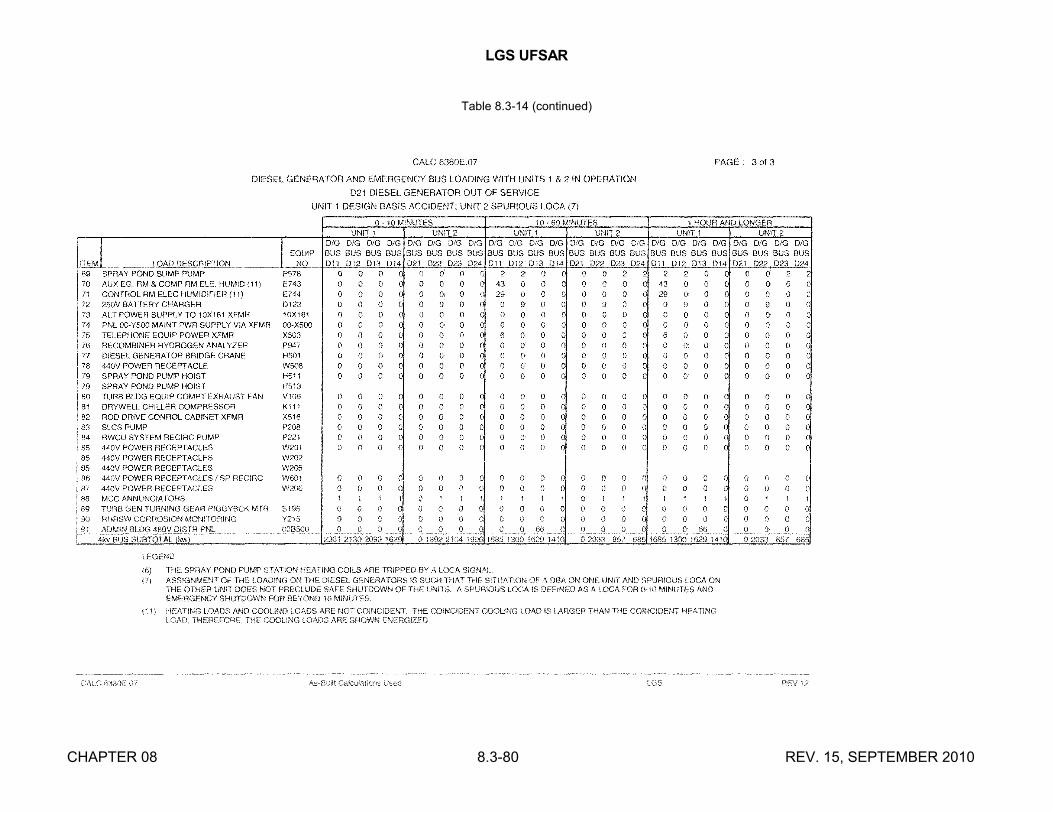
LGS UFSAR
CHAPTER 08 8.3-80 REV. 15, SEPTEMBER 2010
Table 8.3-14 (continued)

LGS UFSAR
CHAPTER 08 8.3-81 REV. 15, SEPTEMBER 2010
Table 8.3-15

LGS UFSAR
CHAPTER 08 8.3-82 REV. 15, SEPTEMBER 2010
Table 8.3-15 (continued)

LGS UFSAR
CHAPTER 08 8.3-83 REV. 15, SEPTEMBER 2010
Table 8.3-15 (continued)

LGS UFSAR
CHAPTER 08 8.3-84 REV. 15, SEPTEMBER 2010
Table 8.3-16

LGS UFSAR
CHAPTER 08 8.3-85 REV. 15, SEPTEMBER 2010
Table 8.3-16 (continued)

LGS UFSAR
CHAPTER 08 8.3-86 REV. 15, SEPTEMBER 2010
Table 8.3-16 (continued)
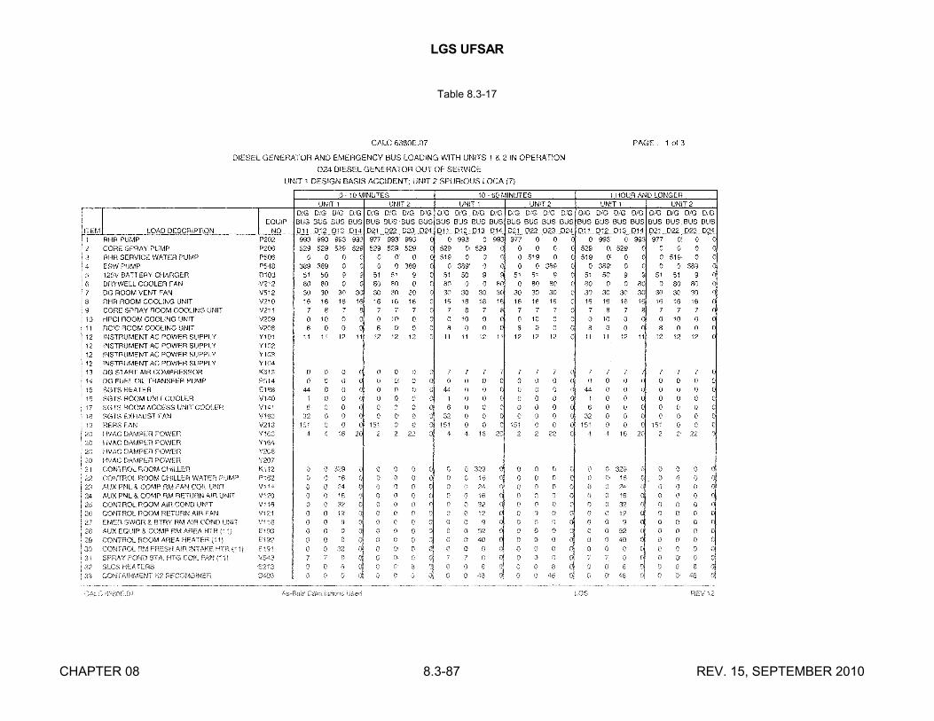
LGS UFSAR
CHAPTER 08 8.3-87 REV. 15, SEPTEMBER 2010
Table 8.3-17

LGS UFSAR
CHAPTER 08 8.3-88 REV. 15, SEPTEMBER 2010
Table 8.3-17 (continued)

LGS UFSAR
CHAPTER 08 8.3-89 REV. 15, SEPTEMBER 2010
Table 8.3-17 (continued)

LGS UFSAR
CHAPTER 08 8.3-90 REV. 16, SEPTEMBER 2012
Table 8.3-18
Table 8.3-18(Deleted)
LGS UFSAR
CHAPTER 08 8.3-91 REV. 16, SEPTEMBER 2012
Table 8.3-18A
Table 8.3-18A(Deleted)

LGS UFSAR
CHAPTER 08 8.3-92 REV. 16, SEPTEMBER 2012
Table 8.3-19
Table 8.3-19(Deleted)

LGS UFSAR
CHAPTER 08 8.3-93 REV. 16, SEPTEMBER 2012
Table 8.3-20
Table 8.3-20(Deleted)

LGS UFSAR
CHAPTER 08 8.3-94 REV. 16, SEPTEMBER 2012
Table 8.3-21
Table 8.3-21(Deleted)

LGS UFSAR
CHAPTER 08 8.3-95 REV. 16, SEPTEMBER 2012
Table 8.3-22
Table 8.3-22(Deleted)

LGS UFSAR
CHAPTER 08 8.3-96 REV. 16, SEPTEMBER 2012
Table 8.3-23
Table 8.3-23(Deleted)
LGS UFSAR
CHAPTER 08 8.3-97 REV. 16, SEPTEMBER 2012
Table 8.3-24
Table 8.3-24(Deleted)

LGS UFSAR
CHAPTER 08 8.3-98 REV. 16, SEPTEMBER 2012
Table 8.3-25
Table 8.3-25(Deleted)

LGS UFSAR
CHAPTER 08 8.3-99 REV. 16, SEPTEMBER 2012
Table 8.3-26
Table 8.3-26(Deleted)

LGS UFSAR
CHAPTER 08 8.3-100 REV. 13, SEPTEMBER 2006
Table 8.3-27
INSTRUMENT AND CONTROL SYSTEMSPOWER SUPPLY PANELS
_________________________________________________________________
Panel Voltage Division
Y101 120 V ac IY102 " IIY103 " IIIY104 " IVY105 " NSY106 " NSY201 " NSY202 " NSY109 " NSY110 " NSAY160 " NSBY160 " NSAD102 125 V dc IBD102 " IICD102 " IIIDD102 " IVAD108 " NSBD108 " NSAY185 120 V ac NSBY185 " NS00Y591 " NS00Y592 " NSY163 " IIIY164 " IV
NS = Nonsafeguard_________________________________________________________________

LGS UFSAR
CHAPTER 08 8.3-101 REV. 16, SEPTEMBER 2012
Table 8.3-28
UNDERVOLTAGE ALARMS
SECTION I
Number Annunciator Status Lights
1 Division I RHR Out-of-Service RHR Pump Breaker ControlPanel AC801, #21 Power Undervoltage
RHR Unit Coolers Out-of-ServiceRHRSW Pump Breaker ControlPower UndervoltageSpray Pond MOV Overload/Loss of PowerSpray Pond HVAC Out-of-ServiceRHR Relays Logic Power Failure RHR MOVs Overload/Loss of PowerRHR Trip Units Out-of-File/ Loss of Power
2 Division II RHR Out-of- Service Same as #1Panel CC801, #21
3 Division III RHR Out-of-Service Same as #1Panel AC801, #36
4 Division IV RHR Out-of-Service Same as #1Panel CC801, #36
5 Division I Core Spray Out- Core Spray Pump Breakerof-Service Control Power UndervoltagePanel AC801, #1 Core Spray Unit Coolers Out-
of-ServiceCore Spray MOVs Overload/Loss of PowerCore Spray Logic Power FailureCore Spray Trip Unit Out-of- File/Power Failure
6 Division II Core Spray Out- Same as #5of-ServicePanel CC801, #1
7 Division III Core Spray Out- Same as #5of-ServicePanel AC801, #11
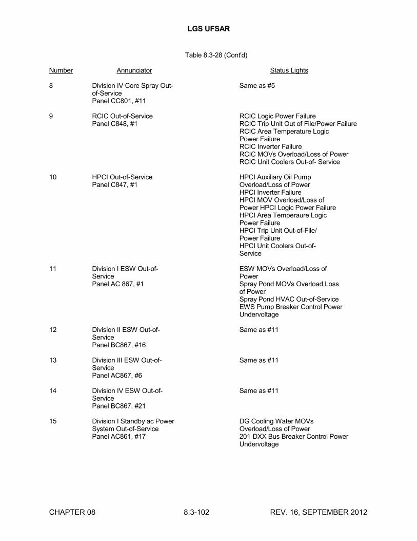
LGS UFSAR
CHAPTER 08 8.3-102 REV. 16, SEPTEMBER 2012
Table 8.3-28 (Cont'd)
Number Annunciator Status Lights
8 Division IV Core Spray Out- Same as #5of-ServicePanel CC801, #11
9 RCIC Out-of-Service RCIC Logic Power FailurePanel C848, #1 RCIC Trip Unit Out of File/Power Failure
RCIC Area Temperature LogicPower FailureRCIC Inverter FailureRCIC MOVs Overload/Loss of PowerRCIC Unit Coolers Out-of- Service
10 HPCI Out-of-Service HPCI Auxiliary Oil PumpPanel C847, #1 Overload/Loss of Power
HPCI Inverter FailureHPCI MOV Overload/Loss ofPower HPCI Logic Power FailureHPCI Area Temperaure LogicPower FailureHPCI Trip Unit Out-of-File/Power FailureHPCI Unit Coolers Out-of-Service
11 Division I ESW Out-of- ESW MOVs Overload/Loss ofService PowerPanel AC 867, #1 Spray Pond MOVs Overload Loss
of PowerSpray Pond HVAC Out-of-ServiceEWS Pump Breaker Control PowerUndervoltage
12 Division II ESW Out-of- Same as #11ServicePanel BC867, #16
13 Division III ESW Out-of- Same as #11ServicePanel AC867, #6
14 Division IV ESW Out-of- Same as #11ServicePanel BC867, #21
15 Division I Standby ac Power DG Cooling Water MOVsSystem Out-of-Service Overload/Loss of PowerPanel AC861, #17 201-DXX Bus Breaker Control Power
Undervoltage

LGS UFSAR
CHAPTER 08 8.3-103 REV. 16, SEPTEMBER 2012
Table 8.3-28 (Cont'd)
Number Annunciator Status Lights
101-DXX Bus Breaker ControlPower UndervoltageSafeguard LC Xmfr. Breaker Control Power UndervoltageCRD Water Pump Breaker Control Power UndervoltageTurbine Enclosure Exhaust FanBreaker Control PowerUndervoltageDrywell Chiller BreakerControl Power UndervoltageDG Not Ready for Autostart
16 Division II Standby ac Same as #15Power System Out-of-ServicePanel BC861, #17
17 Division III Standby ac Same as #15Power System Out-of-ServicePanel CC861, #17
18 Division IV Standby ac Same as #15Power System Out-of-ServicePanel AC802, #17
19 Reactor Isolation System NSSSS Trip Unit Out-of-File/Outboard Out-of-Service Power FailurePanel AC802, #25 NSSSS MOV Overload/Loss of
Power
20 Reactor Isolation System Same as #19Inboard Out-of-ServicePanel AC802, #20
21 Division I ADS Out-of- Relay Logic Power FailureService Trip Unit Out-of-File/PowerPanel C826, #1 Failure
21A Division III ADS Out-of- Same as #21ServicePanel C826, #11
22 RPS System A Trip Unit Out-of-File/Out-of-Service Power FailurePanel BC803, #5
22A RPS System B Out-of- Same as #22ServicePanel BC803, #10

LGS UFSAR
CHAPTER 08 8.3-104 REV. 16, SEPTEMBER 2012
Table 8.3-28 (Cont'd)
SECTION II
Number Bus Voltage Alarm Panel/Window
23 10A101 13.2 kV 11 Unit Auxiliary Bus UV 1BC854/6
24 10A102 13.2 kV 12 Unit Auxiliary Bus UV 1BC854/9
25 20A101 13.2 kV 21 Unit Auxiliary Bus UV 2BC854/26
26 20A102 13.2 kV 22 Unit Auxiliary Bus UV 2BC854/29
27 10 13.2 kV 10 Startup Bus UV 00C860/4
28 20 13.2 kV 20 Startup Bus UV 00C860/24
29 101 4.16 kV 101 Safeguard Bus UV 1AC861/28
30 201 4.16 kV 201 Safeguard Bus UV 1AC861/29
31 D11 4.16 kV D11 Safeguard Bus UV 1AC861/6
32 D12 4.16 kV D12 Safeguard Bus UV 1BC861/6
33 D13 4.16 kV D13 Safeguard Bus UV 1CC861/6
34 D14 4.16 kV D14 Safeguard Bus UV 1DC861/6
35 D21 4.16 kV D21 Safeguard Bus UV 2AC861/6
36 D22 4.16 kV D22 Safeguard Bus UV 2BC861/6
37 D23 4.16 kV D23 Safeguard Bus UV 2CC861/6
38 D24 4.16 kV D24 Safeguard Bus UV 2DC861/6
39 AD102 125 V dc PPA1/A3 125 V dc AC861/33Distribution Panel UV
40 BD501 125 V dc PPA2 125 V dc AC861/34Distribution Panel UV
41 BD102 125 V dc PPB1/B3 125 V dc BC861/34Distribution Panel UV
42 BD501 125 V dc PPB2 125 V dc BC861/35Distribution Panel UV
43 CD102 125 V dc PPC1/C3 125 V dc CC861/32Distribution Panel UV
44 CD501 125 V dc PPC2 125 V dc CC861/33Distribution Panel UV

LGS UFSAR
CHAPTER 08 8.3-105 REV. 16, SEPTEMBER 2012
Table 8.3-28 (Cont'd)
Number Bus Voltage Alarm Panel/Window
45 DD102 125 V dc PPD1/D3 125 V dc DC861/32Distribution Panel UV
46 DD501 125 V dc PPD2 125 V dc DC861/33Distribution Panel UV
47 AD108 125 V dc PP01 125 V dc 1AC854/3Distribution Panel UV 2BC854/18
48 BD108 125 V dc PP02 125 V dc 1AC854/4Distribution Panel UV 2BC854/19
49 CD108 125 V dc PP03 125 V dc 1AC854/5Distribution Panel UV 2BC854/20
50 DD108 125 V dc PP04 125 V dc 1AC854/8Distribution Panel UV 2BC854/25
SECTION III
Number Alarm Panel/Window
51 A RFPT Control Volt Failure BC868/5
52 B RFPT Control Volt Failure BC868/10
53 C RFPT Control Volt Failure BC868/15
54 A RPS/UPS Static Inverter Trouble AC861/5
55 B RPS/UPS Static Inverter Trouble BC861/5
56 RFPT Control Signal Failure AC803/20
57 IRM Downscale AC803/33
58 SRM Downscale AC803/34
59 IRM Upscale/Inop AC803/38
60 SRM Upscale/Inop AC803/39
61 OPRM/APRM Trouble BC803/5
62 Not Used BC803/9
63 Not Used BC803/13
64 RBM Downscale/Trouble BC803/19
65 Not Used BC803/14

LGS UFSAR
CHAPTER 08 8.3-106 REV. 16, SEPTEMBER 2012
Table 8.3-28 (Cont'd)
Number Alarm Panel/Window
66 RPIS Inop BC803/25
67 SLCS Squib Valve Loss of BC803/44Continuity
68 Division 1 Core Spray Trip Unit AC801/5Inverter Power Failure
69 Division 2 Core Spray Trip Unit CC801/5Inverter Power Failure
70 Division 3 Core Spray Trip Unit AC801/15Inverter Power Failure
71 Division 4 Core Spray Trip Unit CC801/15Inverter Power Failure
72 DELETED
73 DELETED
74 Main Steam Line (A/B) Radiation C800/26Monitor Downscale
75 Main Steam Line (C/D) Radiation C800/27Monitor Downscale
76 North Stack Radiation Monitor 00C824/23Downscale
77 South Stack Radiation Monitor 00C824/28Downscale
78 A RPS/UPS Distribution Panel AC861/30Trouble
79 B RPS/UPS Distribution Panel BC861/29Trouble
80 TSC/Computer Trouble 00C855/4
81 A Drywell Chiller Loss of C881/11Control Power
82 B Drywell Chiller Loss of C881/16Control Power
83 SPTMS Trouble Division I AC803/23

LGS UFSAR
CHAPTER 08 8.3-107 REV. 16, SEPTEMBER 2012
Table 8.3-28 (Cont'd)
Number Alarm Panel/Window
84 SPTMS Trouble Division II AC803/24
85 RDCS Inop BC803/24
86 INTENTIONALLY LEFT BLANK
87 CRD Trip Unit Out-of-Service BC803/40
88 CRD Accumulator Trouble BC803/26
89 A Recirculation MG Controller AC802/27Signal Failure (Unit 2 only)
89A A Recirculation ASD Major Failure AC902/07(Unit 1 only)
90 B Recirculation MG Controller BC802/27Signal Failure (Unit 2 only)
90A B Recirculation ASD Major Failure AC902/07(Unit 1 only)
91 1 RFPT Loss of Power AC868/33
92 2 RFPT Loss of Power AC868/38
93 3 RFPT Loss of Power AC868/43
94 Turbine Enclosure HVAC Panel C881/36C126 Trouble
95 Suppression Atmospheric C800/28Analyzer Trouble
96 Drywell Atmospheric C800/4Analyzer Trouble
97 PMS-1 Failover CC861/10

LGS UFSAR
CHAPTER 08 8.3-108 REV. 17, SEPTEMBER 2014
Table 8.3-29
PANEL ALARMS WITH LOSS OF POWERAS POSSIBLE INDIRECT CAUSE
_________________________________________________________________ __
Panel Indication Alarm No. / Name
Y101 Indirect 1 Div. I RHR Out of Service (1)5 Div. I CS Out of Service (1)9 RCIC Out of Service (1)
67 Standby Liquid Squib Valve Loss of Continuity83 Div. I SPOTMOS Trouble94 Turbine Enclosure HVAC Panel C126 Trouble
Y102 Indirect 2 Div. II RHR Out of Service (1)6 Div. II CS Out of Service (1)
10 HPCI Out of Service (1)67 Standby Liquid Squib Valve Loss of Continuity84 Div. II SPOTMOS Trouble94 Turbine Enclosure HVAC Panel C126 Trouble
Y103 Indirect 3 Div. III RHR Out of Service (1)7 Div. III CS Out of Service (1)
67 Standby Liquid Squib Valve Loss of Continuity
Y104 Indirect 4 Div. IV RHR Out of Service (1)8 Div. IV CS Out of Service (1)
Y105 Indirect 94 Turbine Enclosure HVAC Panel C126 Trouble
Y106 Indirect 87 CRD Trip Unit Out of Service88 CRD Accumulator Trouble
Y201 Indirect 56 RFPT Control Signal Failure66 RPIS INOP76 North Stack Radiation Monitor Downscale77 South Stack Radiation Monitor Downscale81 A DW Chiller Loss of Control Power93 C RFPT Loss of Power
Y202 Indirect 76 North Stack Radiation Monitor Downscale77 South Stack Radiation Monitor Downscale82 B DW Chiller Loss of Control Power
AY160 Direct 19 Reactor Isolation System Outboard Out of Service20 Reactor Isolation System Inboard Out of Service22 RPS System A Out of Service54 A RPS / UPS Static Invertor Trouble57 IRM Downscale58 SRM Downscale59 IRM Upscale / Inop60 SRM Upscale / Inop78 A RPS / UPS Distribution Panel Trouble

LGS UFSAR
CHAPTER 08 8.3-109 REV. 17, SEPTEMBER 2014
Table 8.3-29 (Cont’d)
_________________________________________________________________ __
Panel Indication Alarm No. / Name
BY160 Direct 19 Reactor Isolation System Outboard Out of Service20 Reactor Isolation System Inboard Out of Service22A RPS System B Out of Service55 B RPS / UPS Static Inverter Trouble57 IRM Downscale58 SRM Downscale59 IRM Upscale / Inop60 SRM Upscale / Inop79 B RPS / UPS Distribution Panel Trouble
Y109 Indirect 56 RFPT Control Signal Failure
91 A RFPT Loss of Power
Y110 Indirect 56 RFPT Control Signal Failure
92 B RFPT Loss of Power
AD102 Direct 1 Div. I RHR Out of Service5 Div. I CS Out of Service9 RCIC Out of Service
11 Div. I ESW Out of Service15 Div. I Standby ac Power System Out of Service21 Div. I ADS Out of Service39 PPA1/A3 125V dc Distribution Panel UV
BD102 Direct 2 Div. II RHR Out of Service6 Div. II CS Out of Service
10 HPCI Out of Service12 Div. II ESW Out of Service16 Div. II Standby ac Power System Out of Service41 PPB1/B3 125V dc Distribution Panel UV
CD102 Direct 3 Div. III RHR Out of Service7 Div. III CS Out of Service9 RCIC Out of Service
13 Div. III ESW Out of Service17 Div. III Standby ac Power System Out of Service21A Div. III ADS Out of Service43 PPC1/C3 125V dc Distribution Panel UV81 A DW Chiller Loss of Control Power
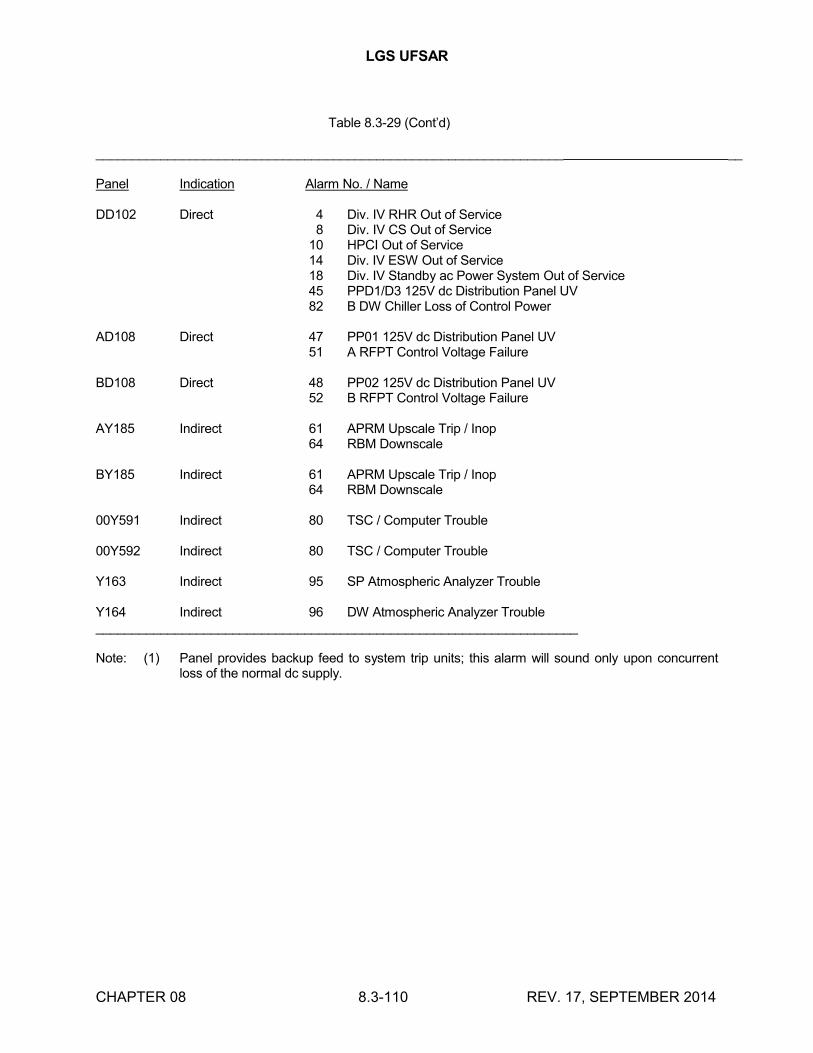
LGS UFSAR
CHAPTER 08 8.3-110 REV. 17, SEPTEMBER 2014
Table 8.3-29 (Cont’d)
_________________________________________________________________ __
Panel Indication Alarm No. / Name
DD102 Direct 4 Div. IV RHR Out of Service8 Div. IV CS Out of Service
10 HPCI Out of Service14 Div. IV ESW Out of Service18 Div. IV Standby ac Power System Out of Service45 PPD1/D3 125V dc Distribution Panel UV82 B DW Chiller Loss of Control Power
AD108 Direct 47 PP01 125V dc Distribution Panel UV51 A RFPT Control Voltage Failure
BD108 Direct 48 PP02 125V dc Distribution Panel UV52 B RFPT Control Voltage Failure
AY185 Indirect 61 APRM Upscale Trip / Inop64 RBM Downscale
BY185 Indirect 61 APRM Upscale Trip / Inop64 RBM Downscale
00Y591 Indirect 80 TSC / Computer Trouble
00Y592 Indirect 80 TSC / Computer Trouble
Y163 Indirect 95 SP Atmospheric Analyzer Trouble
Y164 Indirect 96 DW Atmospheric Analyzer Trouble___________________________________________________________________
Note: (1) Panel provides backup feed to system trip units; this alarm will sound only upon concurrent loss of the normal dc supply.

LGS UFSAR
CHAPTER 08 8.3-111 REV. 13, SEPTEMBER 2006
Table 8.3-30
INSTRUMENTS USED TO ACHIEVE COLD SHUTDOWN
__________________________________________________________________________________________
Parameter Instrument # Bus Evaluation
Reactor Level LR42-1R608 Y109,Y110 ALI42-1R605 Y201 ALI42-1R606A Y109 ALI42-1R606B Y110 ALI42-1R606C BD108 ALI42-1R604 AY160 ALI42-1R610 Y101,AD102 ALR42-1R615 Y102,BD102 AXR42-1R623A Y101,AD102 AXR42-1R623B Y102,BD102 A
Reactor Pressure XR42-1R623A Y101,AD102 AXR42-1R623B Y102,BD102 AXR01-1R609 Y105,Y110 API42-1R605 Y109 A
Vessel Temperature TR42-1R006 Y202 BTR42-1R007 Y202 B
NMS APRM 1 AY185, BY185 OAPRM 2 AY185, BY185 OAPRM 3 AY185, BY185 OAPRM 4 AY185, BY185 ORBM A AY185, BY185 ORBM B AY185, BY185 OSRM A, C AY160 ASRM B, D BY160 AIRM A, C, E, G AY160 AIRM B, D, F, H BY160 ASRM Recorder 602A BY160 ASRM Recorder 602B BY160 AIRM/APRM Recorder BY160 A603AIRM/APRM Recorder BY160 A603BIRM/APRM/RBM BY160 ARecorder 603CIRM/APRM/RBM BY160 ARecorder 603D
RPIS BY185,Y106,Y201, CMCC B130
Condenser Vacuum PR05-101 Y106 DPI05-101A Y106 DPI05-101B Y106 DPI05-101C Y106 D

LGS UFSAR
CHAPTER 08 8.3-112 REV. 13, SEPTEMBER 2006
Table 8.3-30 (Cont'd)
Parameter Instrument # Bus Evaluation
CST level LR08-102,202 Y106,Y105 FLI55-112,212 Y106 FLAHL08-112,212 AD108 F
Standby Liquid LI48-1R601 Y202 EControl Tank Level
Pump Discharge PI48-IN600A Y101,AD102 EPressure PI48-IN600B Y102,BD102 E
PI48-IN600C Y103,CD102 E
Suppression Pool TRS-041-101 Y101 ATemperature TRS-041-103 Y102 A
Suppression Pool LI52-140A Y101,AD102 ALevel LI52-140B Y102 A
LR55-115 Y105,Y106 ALI55-115-1 Y105,Y106 A
Suppression Pool PR57-101 Y101,AD102 APressure PR42-101 Y102,BD102 A
Drywell Pressure PR57-101 Y101,AD102 API42-170-1 Y102,BD102 API42-101 Y101,AD102 API42-170 Y102,BD102 A
Drywell Temperature TI77-101A-H Y202 A,DTR57-110 Y105 A,DTR57-122 Y101 A,D
Turbine 1st Stage PI01-112 Y106,Y105 BPressure
CRD System Flow FI46-R606 Y106 B
HPCI Instrumentation BD102 G
HPCI Turbine-Pump XR - 036-101 Y201 DTemperature XR - 036-102 Y106 DHPCI Turbine VR56-162 Y102 DVibration
RCIC Instrumentation AD102 H
Core Spray InstrumentationA Loop Flow FI52-1R601A Y101,AD102 KB Loop Flow FI52-1R601B Y102,BD102 KA Loop Disch Pressure PI52-1R600A Y101 LB Loop Disch Pressure PI52-1R600B Y102,BD102 L

LGS UFSAR
CHAPTER 08 8.3-113 REV. 13, SEPTEMBER 2006
Table 8.3-30 (Cont'd)
Parameter Instrument # Bus Evaluation
RHR InstrumentationA Loop Flow FI51-1R603A Y101,AD102 MB Loop Flow FI51-1R603B Y102,BD102 MC Loop Flow FI51-1R603C Y103 MD Loop Flow FI51-1R603D Y104 MRHR HX A Discharge PI51-105A Y101 MPressureRHR HX B Discharge PI51-105B Y102 MPressureDeleted
Deleted
Deleted
Deleted
Deleted
Deleted
RHR Service WaterA RHR HX Service Water FI51-1R602A Y101,AD102 MFlowB RHR HX Service Water FI51-1R602B Y102,BD102 MFlowRHR SW Loop A Discharge PI12-001A Y101 NPressureRHR SW Loop B Discharge PI12-001B Y102 NPressureRHR SW A HX Outlet Rad RR12 - OR616A Y103 NRHR SW B HX Outlet Rad RR12 - OR616B Y104 N
RHR SW A Loop Return Rad RR12 - OR615A Y101 NRHR SW B Loop Return Rad RR12 - OR615B Y102 N
Emergency Service WaterESW A Flow FI11-013A Y101 NESW B Flow FI11-013B Y102 NESW A Supply Pressure PI11-003A Y101 NESW B Supply Pressure PI11-003B Y102 N
ADSRelief Valve Position ZYI41-115EF AY185 AIndicationSRV Outlet Temperature XR-036-101 Y201 B
XR-036-102 Y106 B
Containment Instrument GasA Instrument Gas PI59-103A Y103,CD102 BPressureB Instrument Gas PI59-103B Y104,DD102 BPressure

LGS UFSAR
CHAPTER 08 8.3-114 REV. 13, SEPTEMBER 2006
Table 8.3-30 (Cont'd)
Parameter Instrument # Bus Evaluation
Radiation MonitoringNSE-RMS RMMS 00Y591,00Y592 Y201,Y202 DSSE-RMS RMMS 00Y591,00Y592 Y201,Y202 DPCPL-RMS RR26-191A, RMMS Y103,00Y592 APCPL-RMS RR26-191B, RMMS Y102,00Y592 APCPL-RMS RR26-191C, RMMS Y103,00Y592 APCPL-RMS RR26-191D, RMMS Y102,00Y592 A
Containment Atmospheric ControlDrywell 02 AI 57-150 Y164 BDrywell H2 AI 57-151 Y164 BPool 02 AI 57-187 Y163 BPool H2 AI 57-188 Y163 B
EVALUATIONS
A. There is more than one instrument in the control room to monitor this parameter and these instruments are not fed from the same bus; therefore, the loss of one bus will not affect the operator's ability to determine the value of this parameter.
B. This parameter can be determined from other parameters or local instruments if needed. Loss of this parameter would not affect the capability of achieving a cold shutdown condition.
C. The RPIS receives data from the RMCS and is fed from non-Class 1E instrument buses. If power to these buses is lost, rod position indication will be lost in the control room. Loss of rod position indication does not prohibit a manual or automatic SCRAM; therefore, the capability to achieve a cold shutdown condition is not affected by loss of power to the RMCS or the RPIS.
D. Loss of this parameter does not affect the ability to achieve a cold shutdown condition.
E. The SLCS has been redesigned per ATWS requirements. The controls and instrumentation of this system have been designed to perform their function with a single failure; therefore, loss of power to a single division will not prevent the achievement of a cold shutdown condition.

LGS UFSAR
CHAPTER 08 8.3-115 REV. 13, SEPTEMBER 2006
Table 8.3-30 (Cont'd)
F. CST level indication will be lost when Y106 is lost; however, the tank HI/LOW level alarm will still be operable.
G. If power from panel BD102 is lost, the HPCI becomes inoperative. If this occurs, the ADS will be used to depressurize the reactor vessel so that the RCIC and RHR and core spray systems can be used to achieve a cold shutdown condition. Loss of HPCI due to loss of panel BD102 will not affect the ability to achieve a cold shutdown condition.
H. If power from panel AD102 is lost, the RCIC system becomes inoperative. If this occurs, the HPCI system can be used in its place; therefore, the loss of the RCIC system due to the loss of power from panel AD102 will not affect the ability to achieve a cold shutdown condition.
K. Core spray system instrumentation for Loop A is fed from Division 1 Class 1E power. Loop B instrumentation is fed from Division II. Loss of panel Y101 will cause loss of Loop A flow indication in the control room. Loss of Y102 will cause loss of Loop B flow indication. Loss of either of these panels does not affect the operability of the core spray system; therefore, the ability to achieve a cold shutdown condition is not affected.
L. Both of the supply panels must be lost in order to lose indication of this parameter.
M. The RHR system is composed of two redundant loops, each consisting of two pumps and one RHR heat exchanger. The pressure controllers, flow indicators, and pressure indicators for the A loop are fed from separate power panels than those for the B loop. The loss of one bus feeding RHR instrumentation would not affect the operating capability of the RHR system and therefore, would not affect the ability to achieve a cold shutdown.
N. This system has redundant loops. The instrumentation on each loop is fed from separate buses; therefore, the loss of one loop or panel will not affect the ability to achieve a cold shutdown condition with the remaining loop.
O. There is more than one instrument in the control room to monitor this parameter and these instruments are fed by two buses (redundant power); Therefore, the loss of one bus will not affect the operator’s ability to determine the value of this parameter.
______________________________________________________________________
LGS UFSAR
CHAPTER 08 8.3-116 REV. 13, SEPTEMBER 2006
Table 8.3-31 (Deleted)
LGS UFSAR
CHAPTER 08 8.3-117 REV. 13, SEPTEMBER 2006
Table 8.3-32
(The information in this table has been relocated to the TRM)