Embed Size (px)
Citation preview

800-543-9038 USA 866-805-7089 CANADA 203-791-8396 LATIN AMERICA
93
LF24
US
(p. 9
5)LF
24-S
US
(p. 9
5)LF
120
US (p
. 97)
LF12
0-S
US (p
. 97)
LF23
0 US
(p. 9
7)LF
230-
S US
(p. 9
7)LF
24-3
- US
(p. 9
9)
LFC2
4-3-
R US
(p. 1
01)
LFC2
4-3-
S US
(p. 1
01)
LF24
-3-S
US
(p. 9
9)
LF24
-SR
US
(p. 1
03)
S
LF24
-SR
-S U
S (p
. 103
)S
LF24
-SR
-E U
S (p
. 105
)S
LF24
-EC
ON
-R03
US
(p. 1
09)
SLF
24-E
CO
N-R
10 U
S (p
. 109
)S
LF24
-MFT
US
(p. 1
13)
S
LF24
-MFT
-S U
S (p
. 113
)S
LF24
-MFT
-20
US
(p. 1
15)
SLF
24-M
FT-2
0-S
US
(p. 1
15)
S
LF Series Spring Return Direct Coupled Actuator
Minimum 35 in-lb Torque● For damper areas up to 8 sq-ft*
ApplicationsCost effective quality and performancefor a range of applications including:
• Classroom Unit Ventilators • VAV Terminal Units• Fan/Coil Units • Economizer Units• Airhandlers • Control Dampers
AActuators inbold have BDCM
LF Series – At A GlanceTorque: 35 in-lb ● ● ● ● ● ● ● ● ● ● ● ● ● ● ● ● ● ● ●
Power supply: 24 VAC/DC ● ● ● ● ● ● ● ● ● ● ● ● ● ● ●
120 VAC ● ●
230 VAC ● ●
Control signal: On/Off ● ● ● ● ● ●
floating point ● ● ● ●
proportional 2 to 10 VDC ● ● ●
6 to 9 VDC ● ●
multi-function** ● ●
3kΩ NTC type 10 thermistor ●
10kΩ NTC type 7 thermistor ●
Feedback: 2 to 10 VDC ● ● ● ● ●
VDC variable** ● ● ● ●
Auxiliary output, 20 VDC (to power controller) ● ●
Running time motor: <40 to 75 seconds ● ● ● ● ● ●
150 seconds constant ● ● ● ● ●
90 seconds constant ● ●
95 seconds constant ● ●
adj. 75 to 300 seconds*** ● ● ● ●
spring: <25 seconds ● ● ● ● ● ● ● ● ● ● ● ● ● ● ● ● ● ● ●
External direction of rotation switch ● ● ● ● ● ● ● ● ● ● ● ● ●
Plenum rated cable, 18 GA ● ● ● ● ● ●
Conduit fitting ● ● ● ● ● ● ● ● ● ● ● ● ● ● ● ● ● ● ●
Appliance cable, 18 GA ● ● ● ● ● ● ● ● ● ● ● ● ●
Built-in auxiliary switch ● ● ● ● ● ● ● ●
LF24-SR-E US operation ..................(p. 107) Installation instructions ....................(p. 117–120)General wiring .................................(p. 122) Start-up and checkout .....................(p. 123)
*Based on 4 in-lb/ft2 damper torque loading. Parallel blade. No edge seals. **Default 2 to 10 VDC. ***Default 150 seconds.
M40
024
- 05
/10
- Su
bjec
t to
chan
ge. ©
Bel
imo
Airc
ontro
ls (U
SA),
Inc.

800-543-9038 USA 866-805-7089 CANADA 203-791-8396 LATIN AMERICA
94
LF Series Spring Return Direct Coupled Actuator
● Cut labor costs with (10 min. installation) simple direct coupling. ActuatorCenters on 1/2” shaft (K6-1, 3/4” clamp optional).
● True mechanical spring return – the most reliable failsafe.
● Mount for clockwise or counterclockwise fail-safe.
● Easy-to-adjust mechanical stop to limit damper rotation.
● Check damper position easily with clear position indicator.
● Don’t worry about actuator burn-out.Belimo is overload-proof throughout rotation.
● Need to change control direction? Do it easily with a simple switch (modulating actuators).
● Built-in auxiliary switch is easy to use, offers feedback or signal for additional device.
● Microprocessor-controlled brushless DC motor increases actuatorlife span and reliability, provides constant running time (modulating actuators).
● Rugged metal housing withstands rough handling in themechanical room.
● 3 ft. cable and conduit connector eases installation.
AA CLOSER LOOK…
The Belimo Difference
● Customer Commitment. Extensive product range. Application assistance. Same-day shipments. Free technical support. Five year warranty.
● Low Installation and Life-Cycle Cost. Easy installation. Accuracy and repeatability. Low power consumption. No maintenance.
● Long Service Life. Components tested before assembly. Every product tested before shipment. 30+ years direct coupled actuator design.
M40
024
- 05
/10
- Su
bjec
t to
chan
ge. ©
Bel
imo
Airc
ontro
ls (U
SA),
Inc.

800-543-9038 USA 866-805-7089 CANADA 203-791-8396 LATIN AMERICA
95
LF24(-S) US On/Off, Spring Return, 24V
Torque min. 35 in-lb, for control of air dampers
ApplicationFor On/Off, fail-safe control of dampers in HVAC systems. Actuator sizing should bedone in accordance with the damper manufacturer’s specifications. Control is On/Off from an auxiliary contact, digital output, or a manual switch.
The actuator is mounted directly to a damper shaft from 3/8” up to 1/2” in diameterby means of its universal clamp, 1/2” shaft centered at delivery. For shafts up to 3/4”use K6-1 accessory. A crank arm and several mounting brackets are available forapplications where the actuator cannot be direct coupled to the damper shaft.
OperationThe LF series actuators provide true spring return operation for reliable fail-safe application and positive close off on air tight dampers. The spring return system provides consistent torque to the damper with, and without, power applied to the actuator.
The LF series provides 95° of rotation and is provided with a graduated positionindicator showing 0° to 95°.
The actuator may be stalled anywhere in its normal rotation without the need of mechanical end switches. Power consumption is reduced in holding mode.
The LF24-S US version is provided with one built in auxiliary switch. This SPDT switchis provided for safety interfacing or signaling, for example, for fan start-up. Theswitching function is adjustable between 0° and 95°. The auxiliary switch in theLF24-S is double insulated so an electrical ground connection is not necessary.
Dimensions (Inches [mm])
0.39" [10]
7.67" [195]
3.66" [93]
1.93"[49]
6.10" [155]
3.15" [80]3.86"[98]
0.256" [6.5]0.98"[25]
4.92" [125]
0.79"[20]
0.5"[12.7]
0.71" [18]
0.74" [18.7]
2.24"[57]
3.23" [82]
0.25" [6.3]
Standard: 3/8" to 1/2"
3/8" to 7/16" Optional
1/2" to 3/4" w/K6-1 accessory
D010
Technical Data LF24(-S) US
Power supply 24 VAC ± 20% 50/60 Hz24 VDC ± 10%
Power consumption running 5 Wholding 2.5 W
Transformer sizing 7 VA (class 2 power source)Electrical connection(LF24-S US has 2 cables)
3 ft, 18 GA appliance cable1/2” conduit connector
Overload protection electronic throughout 0 to 95° rotationAngle of rotation max. 95°, adjust. with mechanical stopTorque 35 in-lb [4 Nm] Direction of rotation reversible with cw/ccw mountingPosition indication visual indicator, 0° to 95°
(0° is spring return position)Running time motor < 40 to 75 sec(nominal) spring < 25 sec @-4°F to 122°F [-20°C to 50°C]
< 60 sec @-22°F [-30°C]Humidity 5 to 95% RH non-condensingAmbient temperature -22°F to 122°F [-30°C to 50°C]Storage temperature -40°F to 176°F [-40°C to 80°C]Housing NEMA type 2 / IP54Housing material zinc coated steelAgency listings cULus acc. to UL 873 and
CAN/CSA C22.2 No. 24-93Noise level (max) running < 50 db (A)
spring return 62 dB (A)Servicing maintenance freeQuality standard ISO 9001Weight LF24
LF24-S3.1 lbs (1.40 kg)3.2 lbs (1.45 kg)
LF24-S US
Auxiliary switch 1 x SPDT 3A (0.5A) @ 250 VAC, UL Approvedadjustable 0° to 95° (double insulated)
M40
024
- 05
/10
- Su
bjec
t to
chan
ge. ©
Bel
imo
Airc
ontro
ls (U
SA),
Inc.

800-543-9038 USA 866-805-7089 CANADA 203-791-8396 LATIN AMERICA
96
Wiring Diagrams
1 Provide overload protection and disconnect as required.
2 CAUTION Equipment Damage!Actuators may be connected in parallel.Power consumption and input impedance must be observed.
3 Actuators may also be powered by 24 VDC.
4For end position indication, interlock control, fan startup, etc., LF24-S USincorporates a built-in auxiliary switch: 1 x SPDT, 3A (0.5A) @250 VAC, ULApproved, adjustable 0° to 95°.
Meets cULus requirements without the need of an electrical ground con-nection.
WARNING Live Electrical Components!G During installation, testing, servicing and troubleshooting of this product, it may be
necessary to work with live electrical components. Have a qualifi ed licensed electrician or otherindividual who has been properly trained in handling live electrical components perform these tasks. Failure to follow all electrical safety precautions when exposed to live electrical compo-nents could result in death or serious injury.
1 Common
2 + Hot
2
24 VAC Transformer
LF24 US
Line Volts 3
W04
7
On/Off wiring for LF24 US
1 Common
2 + Hot
2
24 VAC Transformer
LF24-S US
Line Volts 3
4S1
S2
S3
NC
NO0° to 95°
W04
8
On/Off wiring for LF24-S US
LF24(-S) US On/Off, Spring Return, 24V
Accessories
AV 10-18 Shaft extension (K6-1 is required)IND-LF Damper position indicatorK6-1 Universal clamp for up to 3/4” diameter shaftsKH-LF Crank arm for up to 1/2” round shaftTool-06 8mm and 10 mm wrenchZG-LF2 Crank arm adaptor kit for LF ZG-112 Mounting bracket for Honeywell Mod IV, M6415
type actuators, and new installationsZG-LF112 Crank arm adaptor kit for Honeywell Mod IV,
M6415 type actuators, and new installationsZS-100 Weather shield (metal)ZS-150 Weather shield (polycarbonate)ZS-260 Explosion-proof housingNOTE: When using LF24 US and LF24-S US actuators, only use accessories listed on this page.
For actuator wiring information and diagrams, refer to Belimo Wiring Guide.
Typical Specification
On/Off spring return damper actuators shall be direct coupled type which require no crank arm and linkage and be capable of direct mounting to a shaft up to a 3/4”diameter and center a 1/2” shaft. The actuators must be designed so that they may beused for either clockwise or counterclockwise fail-safe operation. Actuators shall beprotected from overload at all angles of rotation. If required, one SPDT auxiliary switchshall be provided having the capability of being adjustable. Actuators with auxiliaryswitch must be constructed to meet the requirements for Double Insulation so anelectrical ground is not required to meet agency listings. Actuators shall be cULus listed, have a 5 year warranty, and be manufactured under ISO 9001 International Quality Control Standards. Actuators shall be as manufactured by Belimo.
M40
024
- 05
/10
- Su
bjec
t to
chan
ge. ©
Bel
imo
Airc
ontro
ls (U
SA),
Inc.
800-543-9038 USA 866-805-7089 CANADA 203-791-8396 LATIN AMERICA
97
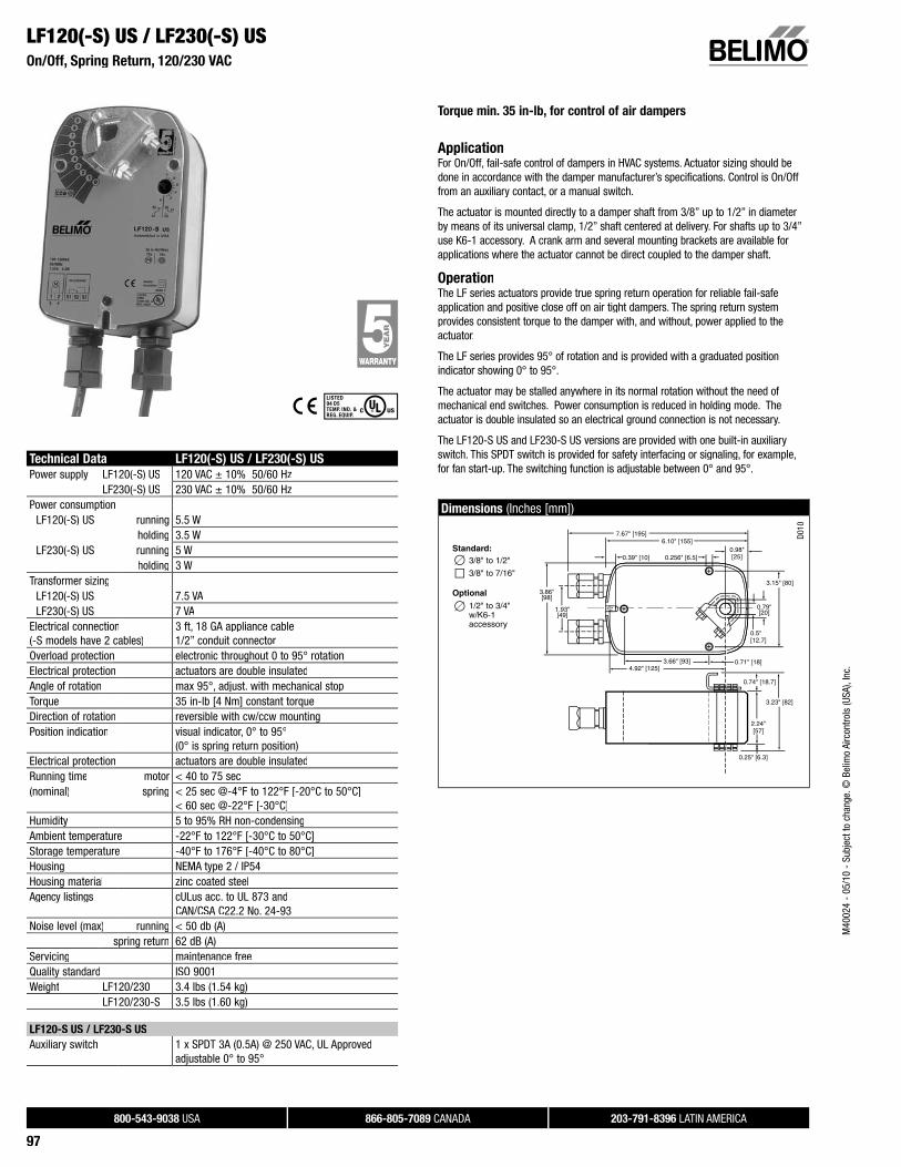
Torque min. 35 in-lb, for control of air dampers
ApplicationFor On/Off, fail-safe control of dampers in HVAC systems. Actuator sizing should bedone in accordance with the damper manufacturer’s specifications. Control is On/Off from an auxiliary contact, or a manual switch.
The actuator is mounted directly to a damper shaft from 3/8” up to 1/2” in diameterby means of its universal clamp, 1/2” shaft centered at delivery. For shafts up to 3/4”use K6-1 accessory. A crank arm and several mounting brackets are available forapplications where the actuator cannot be direct coupled to the damper shaft.
OperationThe LF series actuators provide true spring return operation for reliable fail-safe application and positive close off on air tight dampers. The spring return system provides consistent torque to the damper with, and without, power applied to the actuator.
The LF series provides 95° of rotation and is provided with a graduated positionindicator showing 0° to 95°.
The actuator may be stalled anywhere in its normal rotation without the need of mechanical end switches. Power consumption is reduced in holding mode. Theactuator is double insulated so an electrical ground connection is not necessary.
The LF120-S US and LF230-S US versions are provided with one built-in auxiliaryswitch. This SPDT switch is provided for safety interfacing or signaling, for example, for fan start-up. The switching function is adjustable between 0° and 95°.
Dimensions (Inches [mm])
0.39" [10]
7.67" [195]
3.66" [93]
1.93"[49]
6.10" [155]
3.15" [80]3.86"[98]
0.256" [6.5]0.98"[25]
4.92" [125]
0.79"[20]
0.5"[12.7]
0.71" [18]
0.74" [18.7]
2.24"[57]
3.23" [82]
0.25" [6.3]
Standard: 3/8" to 1/2"
3/8" to 7/16" Optional
1/2" to 3/4" w/K6-1 accessory
D010
LF120(-S) US / LF230(-S) USOn/Off, Spring Return, 120/230 VAC
Technical Data LF120(-S) US / LF230(-S) US
Power supply LF120(-S) US 120 VAC ± 10% 50/60 HzLF230(-S) US 230 VAC ± 10% 50/60 Hz
Power consumptionLF120(-S) US running 5.5 W
holding 3.5 WLF230(-S) US running 5 W
holding 3 WTransformer sizing
LF120(-S) US 7.5 VALF230(-S) US 7 VA
Electrical connection(-S models have 2 cables)
3 ft, 18 GA appliance cable1/2” conduit connector
Overload protection electronic throughout 0 to 95° rotationElectrical protection actuators are double insulatedAngle of rotation max 95°, adjust. with mechanical stopTorque 35 in-lb [4 Nm] constant torqueDirection of rotation reversible with cw/ccw mountingPosition indication visual indicator, 0° to 95°
(0° is spring return position)Electrical protection actuators are double insulatedRunning time motor < 40 to 75 sec(nominal) spring < 25 sec @-4°F to 122°F [-20°C to 50°C]
< 60 sec @-22°F [-30°C]Humidity 5 to 95% RH non-condensingAmbient temperature -22°F to 122°F [-30°C to 50°C]Storage temperature -40°F to 176°F [-40°C to 80°C]Housing NEMA type 2 / IP54Housing material zinc coated steelAgency listings cULus acc. to UL 873 and
CAN/CSA C22.2 No. 24-93Noise level (max) running < 50 db (A)
spring return 62 dB (A)Servicing maintenance freeQuality standard ISO 9001Weight LF120/230 3.4 lbs (1.54 kg)
LF120/230-S 3.5 lbs (1.60 kg)
LF120-S US / LF230-S US
Auxiliary switch 1 x SPDT 3A (0.5A) @ 250 VAC, UL Approvedadjustable 0° to 95°
M40
024
- 05
/10
- Su
bjec
t to
chan
ge. ©
Bel
imo
Airc
ontro
ls (U
SA),
Inc.

800-543-9038 USA 866-805-7089 CANADA 203-791-8396 LATIN AMERICA
98
LF120(-S) US / LF230(-S) USOn/Off, Spring Return, 120/230 VAC
Accessories
AV 10-18 Shaft extension (K6-1 is required)IND-LF Damper position indicatorK6-1 Universal clamp for up to 3/4” diameter shaftsKH-LF Crank arm for up to 1/2” round shaftTool-06 8mm and 10 mm wrenchZG-LF2 Crank arm adaptor kit for LFZG-112 Mounting bracket for Honeywell Mod IV, M6415
type actuators, and new installationsZG-LF112 Crank arm adaptor kit for Honeywell Mod IV,
M6415 type actuators, and new installations ZS-100 Weather shield (metal)ZS-150 Weather shield (polycarbonate)ZS-260 Explosion-proof housingNOTE: When using LF120/230 US & LF120-S/230-S US actuators, only use accessories listed on this page.
For actuator wiring information and diagrams, refer to Belimo Wiring Guide.
Typical Specification
On/Off spring return damper actuators shall be direct coupled type which requireno crank arm and linkage and be capable of direct mounting to a shaft up to a 3/4” diameter and center a 1/2” shaft. The actuators must be designed so that they maybe used for either clockwise or counterclockwise fail-safe operation. Actuators shall be protected from overload at all angles of rotation. If required, one SPDT auxiliaryswitch shall be provided having the capability of being adjustable. Actuators must be constructed to meet the requirements for Double Insulation so an electrical groundis not required to meet agency listings. Actuators shall be cULus listed, have a 5 year warranty, and be manufactured under ISO 9001 International Quality Control Standards. Actuators shall be as manufactured by Belimo.
Wiring Diagrams
1 Provide overload protection and disconnect as required.
2 CAUTION Equipment Damage!Actuators may be connected in parallel.Power consumption and input impedance must be observed.
3 No ground connection is required.
4For end position indication, interlock control, fan startup, etc., LF120-S USand LF230-S US incorporate one built-in auxiliary switch: 1 x SPDT, 3A (0.5A) @250 VAC, UL Approved, adjustable 0° to 95°.
Meets cULus requirements without the need of an electrical ground con-nection.
WARNING Live Electrical Components!G During installation, testing, servicing and troubleshooting of this product, it may be
necessary to work with live electrical components. Have a qualifi ed licensed electrician or otherindividual who has been properly trained in handling live electrical components perform these tasks. Failure to follow all electrical safety precautions when exposed to live electrical compo-nents could result in death or serious injury.
1 Neutral
2 Hot1
2
120 VAC 230 VAC
LF120 US LF230 US
3L1 N
L2 H
W04
9
On/Off wiring for LF120 US / LF230 US
W05
0_08
On/Off wiring for LF120-S US / LF230-S US
M40
024
- 05
/10
- Su
bjec
t to
chan
ge. ©
Bel
imo
Airc
ontro
ls (U
SA),
Inc.

800-543-9038 USA 866-805-7089 CANADA 203-791-8396 LATIN AMERICA
99
LF24-3(-S) US On/Off, Floating Point, Spring Return, 24V
Torque min. 35 in-lb, for control of air dampers
ApplicationFor modulation or On/Off control of dampers in HVAC systems. Actuator sizing should be done in accordance with the damper manufacturer’s specifications.
The actuator is mounted directly to a damper shaft from 3/8” up to 1/2” in diameterby means of its universal clamp, 1/2” shaft centered at delivery. For shafts up to 3/4”use K6-1 accessory. A crank arm and several mounting brackets are available forapplications where the actuator cannot be direct coupled to the damper shaft.
Control is floating point from a triac or relay, or On/Off from an auxiliary contact from afan motor contactor, controller, or manual switch.
OperationThe LF series actuators provide true spring return operation for reliable fail-safe application and positive close-off on air tight dampers. The spring return system provides consistent torque to the damper with, and without, power applied to the actuator.
The LF series provides 95° of rotation and is provided with a graduated positionindicator showing 0 to 95°.
The LF24-3 (-S) US uses a brushless DC motor which is controlled by an ApplicationSpecific Integrated Circuit (ASIC) and a microprocessor. The microprocessor provides the intelligence to the ASIC to provide a constant rotation rate. The ASIC monitors andcontrols the brushless DC motor’s rotation and provides a digital rotation sensingfunction to prevent damage to the actuator in a stall condition. The actuator may be stalled anywhere in its normal rotation without the need of mechanical end switches.
Power consumption is reduced in holding mode.
The LF24-3-S US version is provided with one built-in auxiliary switch. This SPDTswitch is provided for safety interfacing or signaling, for example, for fan start-up. Theswitching function is adjustable between 0° and 95°. The auxiliary switch in theLF24-3-S US is double insulated so an electrical ground is not necessary.
Dimensions (Inches [mm])
0.39" [10]
7.67" [195]
3.66" [93]
1.93"[49]
6.10" [155]
3.15" [80]3.86"[98]
0.256" [6.5]0.98"[25]
4.92" [125]
0.79"[20]
0.5"[12.7]
0.71" [18]
0.74" [18.7]
2.24"[57]
3.23" [82]
0.25" [6.3]
Standard: 3/8" to 1/2"
3/8" to 7/16" Optional
1/2" to 3/4" w/K6-1 accessory
D010
Technical Data LF24-3(-S) US
Power supply 24 VAC ± 20% 50/60 Hz24 VDC ± 10%
Power consumptionrunning 2.5 Wholding 1 W
Transformer sizing 5 VA (class 2 power source)Electrical connection
LF24-3 US 3 ft, plenum rated cable1/2” conduit connector
LF24-3-S US 3 ft, 18 GA appliance cables (2)1/2” conduit connectors
Overload protection electronic throughout 0 to 95° rotationInput impedance 1000 Ω (0.6w) control inputsAngle of rotation max. 95°, adjust. with mechanical stopTorque 35 in-lb [4 Nm] Direction of rotation
spring reversible with cw/ccw mountingmotor reversible with built-in switch
Position indication visual indicator, 0° to 95°(0° is spring return position)
Running time motor 150 sec constant, independent of loadspring < 25 sec @-4°F to 122°F [-20°C to 50°C]
< 60 sec @-22°F [-30°C]Humidity 5 to 95% RH non-condensingAmbient temperature -22°F to 122°F [-30°C to 50°C]Storage temperature -40°F to 176°F [-40°C to 80°C]Housing NEMA type 2 /IP54Housing material zinc coated metalAgency listings cULus acc. to UL 873 and
CAN/CSA C22.2 No. 24-93Noise level (max) running < 30 db (A)Servicing maintenance freeQuality standard ISO 9001Weight LF24-3
LF24-3-S 3.1 lbs (1.40 kg) 3.6 lbs (1.45 kg)
LF24-3-S US
Auxiliary switch 1 x SPDT 3A (0.5A) @ 250 VAC, UL Approvedadjustable 0° to 95° (double insulated)
M40
024
- 05
/10
- Su
bjec
t to
chan
ge. ©
Bel
imo
Airc
ontro
ls (U
SA),
Inc.

800-543-9038 USA 866-805-7089 CANADA 203-791-8396 LATIN AMERICA
100
LF24-3(-S) US On/Off, Floating Point, Spring Return, 24V
Accessories
AV 10-18 Shaft extension (K6-1 is required)IND-LF Damper position indicator K6-1 Universal clamp for up to 3/4” diameter shaftsKH-LF Crank arm for up to 1/2” round shaftTool-06 8mm and 10 mm wrenchZG-LF2 Crank arm adaptor kit for LF ZG-112 Mounting bracket for Honeywell Mod IV, M6415 type actuators,
and new installationsZG-LF112 Crank arm adaptor kit for Honeywell Mod IV,
M6415 type actuators, and new installationsZS-100 Weather shield (metal)ZS-150 Weather shield (polycarbonate)ZS-260 Explosion-proof housingNOTE: When using LF24-3 (-S) US actuators, only use accessories listed on this page.
For actuator wiring information and diagrams, refer to Belimo Wiring Guide.
Typical Specification
Floating point, On/Off spring return damper actuators shall be direct coupled type which require no crank arm and linkage and be capable of direct mounting to ashaft up to a 3/4” diameter and center a 1/2” shaft. The actuators must be designed so that they may be used for either clockwise or counterclockwise fail-safeoperation. Actuators shall have an external direction of rotation switch to reverse control logic. Actuators shall use a brushless DC motor and be protected from overload at all angles of rotation. If required, one SPDT auxiliary switch shall beprovided having the capability of being adjustable. Actuators with auxiliary switch must be constructed to meet the requirements for Double Insulation so an electricalground is not required to meet agency listings. Run time shall be constant andindependent of torque. Actuators shall be cULus listed, have a 5 year warranty, andbe manufactured under ISO 9001 International Quality Control Standards. Actuatorsshall be as manufactured by Belimo.
Wiring Diagrams
1 Provide overload protection and disconnect as required.
2 CAUTION Equipment Damage!Actuators may be connected in parallel.Power consumption and input impedance must be observed.
3 Actuators may also be powered by 24 VDC.
4The Common connection from the actuator must be connected to the Hotconnection of the controller.
5 The actuator Hot must be connected to the control board Common.
6For end position indication, interlock control, fan startup, etc., LF24-3-S USLF120-S US and LF230-S US incorporate one built-in auxiliary switch: 1 xSPDT, 3A (0.5A) @250 VAC, UL Approved, adjustable 0° to 95°.
8Actuators with plenum rated cable do not have numbers on wires; use colorcoded instead. Actuators with appliance rated cable use numbers.✝ LF24-3 US, Green wire #4, LF24-3-S US, White wire #5
Meets cULus requirements without the need of an electrical ground con-nection.
WARNING Live Electrical Components!G During installation, testing, servicing and troubleshooting of this product, it may be
necessary to work with live electrical components. Have a qualifi ed licensed electrician or other individual who has been properly trained in handling live electrical components perform these tasks. Failure to follow all electrical safety precautions when exposed to live electrical compo-nents could result in death or serious injury.
W05
1
On/Off wiring
for LF24-3(-S) US
W05
2
Floating Point wiring
for LF24-3(-S) US
LF24-3-S US
6S1
S2
S3
NC
NO0° to 95°
W05
3
Auxiliary switch
of LF24-3(-S) US
Triac source
W05
5
Triac sink
W05
6
Triac sink with separate transformers
M40
024
- 05
/10
- Su
bjec
t to
chan
ge. ©
Bel
imo
Airc
ontro
ls (U
SA),
Inc.

800-543-9038 USA 866-805-7089 CANADA 203-791-8396 LATIN AMERICA
101
LFC24-3-R(-S) USOn/Off, Floating Point, Spring Return, 24V, Trane Voyager Retrofi t
Torque min. 35 in-lb, for control of air dampers
ApplicationFor modulation or On/Off control of dampers in HVAC systems. Actuator sizing should be done in accordance with the damper manufacturer’s specifications.
The actuator is mounted directly to a damper shaft from 3/8” up to 1/2” in diameterby means of its universal clamp, 1/2” shaft centered at delivery. For shafts up to 3/4”use K6-1 accessory. The ZG-LFC114 universal mounting kit can be used with theLFC24-3-R US actuator for retrofit of the economizer section of the Trane Voyager unit.
Control is floating point from a triac or relay, or On/Off from an auxiliary contact from afan motor contactor, controller, or manual switch.
OperationThe LF series actuators provide true spring return operation for reliable fail-safe application and positive close-off on air tight dampers. The spring return system provides consistent torque to the damper with, and without, power applied to the actuator.
The LF series provides 95° of rotation and is provided with a graduated positionindicator showing 0 to 95°.
The LFC24-3-R (-S) US uses a brushless DC motor which is controlled by an Application Specific Integrated Circuit (ASIC) and a microprocessor. The microprocessor provides the intelligence to the ASIC to provide a constant rotationrate. The ASIC monitors and controls the brushless DC motor’s rotation and provides adigital rotation sensing function to prevent damage to the actuator in a stall condition. The actuator may be stalled anywhere in its normal rotation without the need of mechanical end switches.
Power consumption is reduced in holding mode.
The LFC24-3-S US version is provided with one built-in auxiliary switch. This SPDTswitch is provided for safety interfacing or signaling, for example, for fan start-up. Theswitching function is adjustable between 0° and 95°. The auxiliary switch in theLFC24-3-S US is double insulated so an electrical ground is not necessary.
Dimensions (Inches [mm])
0.39" [10]
7.67" [195]
3.66" [93]
1.93"[49]
6.10" [155]
3.15" [80]3.86"[98]
0.256" [6.5]0.98"[25]
4.92" [125]
0.79"[20]
0.5"[12.7]
0.71" [18]
0.74" [18.7]
2.24"[57]
3.23" [82]
0.25" [6.3]
Standard: 3/8" to 1/2"
3/8" to 7/16" Optional
1/2" to 3/4" w/K6-1 accessory
D010
Technical Data LFC24-3-R(-S) US
Power supply 24 VAC ± 20% 50/60 Hz24 VDC ± 10%
Power consumptionrunning 2.5 Wholding 1 W
Transformer sizing 5 VA (class 2 power source)Electrical connection
LFC24-3-R US 3 ft, plenum rated cable 4 male spade connectors
LFC24-3-S US 3 ft, 18 GA appliance cables (2)1/2” conduit connectors
Overload protection electronic throughout 0 to 95° rotationInput impedance 1000 Ω (0.6w) control inputsAngle of rotation max. 95°, adjust. with mechanical stopTorque 35 in-lb [4 Nm] Direction of rotation
spring reversible with cw/ccw mountingmotor reversible with built-in switch
Position indication visual indicator, 0° to 95°(0° is spring return position)
Running time motor 90 sec constant, independent of loadspring < 25 sec @-4°F to 122°F [-20°C to 50°C]
< 60 sec @-22°F [-30°C]Humidity 5 to 95% RH non-condensingAmbient temperature -22°F to 122°F [-30°C to 50°C]Storage temperature -40°F to 176°F [-40°C to 80°C]Housing NEMA type 2 /IP54Housing material zinc coated metalAgency listings cULus acc. to UL 873 and
CAN/CSA C22.2 No. 24-93Noise level (max) running < 30 db (A)
spring return 62 dB (A)Servicing maintenance freeQuality standard ISO 9001Weight LFC24-3-R US 3.1 lbs (1.40 kg)
LFC24-3-S US 3.6 lbs (1.45 kg)
LFC24-3-S US
Auxiliary switch 1 x SPDT 3A (0.5A) @ 250 VAC, UL Approvedadjustable 0° to 95° (double insulated)
M40
024
- 05
/10
- Su
bjec
t to
chan
ge. ©
Bel
imo
Airc
ontro
ls (U
SA),
Inc.

800-543-9038 USA 866-805-7089 CANADA 203-791-8396 LATIN AMERICA
102
LFC24-3-R(-S) USOn/Off, Floating Point, Spring Return, 24V, Trane Voyager Retrofi t
Wiring Diagrams
1 Provide overload protection and disconnect as required.
2 CAUTION Equipment Damage!Actuators may be connected in parallel.Power consumption and input impedance must be observed.
3 No ground connection is required.
6For end position indication, interlock control, fan startup, etc., LFC24-3-SUS incorporates one built-in auxiliary switch: 1 x SPDT, 3A (0.5A) @250VAC, UL Approved, adjustable 0° to 95°. LFC24-3-S US has a white wire #5instead of a green wire #4.
8Actuators with plenum rated cable do not have numbers on wires; use color coded instead. Actuators with appliance rated cable use numbers.
Meets cULus requirements without the need of an electrical ground con-nection.
WARNING Live Electrical Components!G During installation, testing, servicing and troubleshooting of this product, it may be
necessary to work with live electrical components. Have a qualifi ed licensed electrician or otherindividual who has been properly trained in handling live electrical components perform these tasks. Failure to follow all electrical safety precautions when exposed to live electrical compo-nents could result in death or serious injury.
bCCC WCWW
stop
a(3) (4)
stop stop stop
Direction of Rotation Switchxx
xx
xxxx
xx
xx
xx
xx
xxx
xxxx
xxxx
xx
xx
xx
xx
xxx
CWCCWSwitch
Positions
CCC WCW
Line Volts
The indication of direction is valid for switch position CW.
Blk (1) Common
Red (2) +
Wht (3) +
Grn (4) +
24 VAC Transformer
LFC24-3-R USLFC24-3-S US
CW CCW
xxxx
xxxx
xx
xx
xx
xx
xxx
xxxx
xxxx
xx
xx
xx
xx
xxx
a
b
W14
7
Floating point control of LFC24-3… US
W14
9_08
Wiring LFC24-3-R US
Auxiliary switch of LFC24-3-S US
Accessories
AV 10-18 Shaft extension (K6-1 is required)IND-LF Damper position indicator K6-1 Universal clamp for up to 3/4” diameter shaftsKH-LF Crank arm for up to 1/2” round shaftTool-06 8mm and 10 mm wrenchZG-LF2 Crank arm adaptor kit for LF ZG-112 Mounting bracket for Honeywell Mod IV, M6415 type actuators,
and new installationsZG-LF112 Crank arm adaptor kit for Honeywell Mod IV,
M6415 type actuators, and new installationsZG-LFC114 Used with LFC24-3-R US, mounting bracket kit for Trane
Voyager economizer actuator retrofit. Kit includes
mounting bracket and installation hardware.
ZS-100 Weather shield (metal)ZS-150 Weather shield (polycarbonate)ZS-260 Explosion-proof housingNOTE: When using LFC24-3-R (-S) US actuators, only use accessories listed on this page.
NOTE: For On/Off control wiring please see LF24-3 US wiring diagram. “On/Off control of LF24-3(-S) US”page 71.
NOTE: For Floating point control wiring, Triac source, sink or wiring with separate power supplies please seepage 71 for correct wiring.
For actuator wiring information and diagrams, refer to Belimo Wiring Guide.
ZG-LFC114
Retrofi t solution installation
Typical Specification
Floating point, On/Off spring return damper actuators shall be direct coupled type which require no crank arm and linkage and be capable of direct mounting to a shaftup to a 3/4” diameter and center a 1/2” shaft. The actuators must be designed so thatthey may be used for either clockwise or counterclockwise fail-safe operation. Actua-tors shall have an external direction of rotation switch to reverse control logic. Actuatorsshall use a brushless DC motor and be protected from overload at all angles of rotation.If required, one SPDT auxiliary switch shall be provided having the capability of beingadjustable. Actuators with auxiliary switch must be constructed to meet the require-ments for Double Insulation so an electrical ground is not required to meet agencylistings. Run time shall be constant and independent of torque. Actuators shall be cULuslisted, have a 5 year warranty, and be manufactured under ISO 9001 International Qual-ity Control Standards. Actuators shall be as manufactured by Belimo.
M40
024
- 05
/10
- Su
bjec
t to
chan
ge. ©
Bel
imo
Airc
ontro
ls (U
SA),
Inc.

800-543-9038 USA 866-805-7089 CANADA 203-791-8396 LATIN AMERICA
103
Torque min. 35 in-lb, for control of air dampers
ApplicationFor proportional modulation of dampers in HVAC systems. Actuator sizing should be done in accordance with the damper manufacturer’s specifications.
The actuator is mounted directly to a damper shaft from 3/8” up to 1/2” in diameterby means of its universal clamp, 1/2” shaft centered at delivery. For shafts up to 3/4”use K6-1 accessory. A crank arm and several mounting brackets are available forapplications where the actuator cannot be direct coupled to the damper shaft.
The actuator operates in response to a 2 to 10 VDC, or with the addition of a 500Wresistor, a 4 to 20 mA control input from an electronic controller or positioner. A 2 to10 VDC feedback signal is provided for position indication or master-slave applications.
OperationThe LF series actuators provide true spring return operation for reliable fail-safe application and positive close-off on air tight dampers. The spring return system provides consistent torque to the damper with, and without, power applied to the actuator.
The LF series provides 95° of rotation and is provided with a graduated positionindicator showing 0 to 95°.
The LF24-SR (-S) US uses a brushless DC motor which is controlled by an ApplicationSpecific Integrated Circuit (ASIC) and a microprocessor. The microprocessor provides the intelligence to the ASIC to provide a constant rotation rate and to know theactuator’s exact fail-safe position. The ASIC monitors and controls the brushless DC motor’s rotation and provides a digital rotation sensing function to prevent damage tothe actuator in a stall condition. The actuator may be stalled anywhere in its normal rotation without the need of mechanical end switches. Power consumption is reducedin holding mode.
The LF24-SR-S US version is provided with one built-in auxiliary switch. This SPDTswitch is provided for safety interfacing or signaling, for example, for fan start-up. Theswitching function is adjustable between 0° and 95°. The auxiliary switch in theLF24-SR-S US is double insulated so an electrical ground in not necessary.
Dimensions (Inches [mm])
0.39" [10]
7.67" [195]
3.66" [93]
1.93"[49]
6.10" [155]
3.15" [80]3.86"[98]
0.256" [6.5]0.98"[25]
4.92" [125]
0.79"[20]
0.5"[12.7]
0.71" [18]
0.74" [18.7]
2.24"[57]
3.23" [82]
0.25" [6.3]
Standard: 3/8" to 1/2"
3/8" to 7/16" Optional
1/2" to 3/4" w/K6-1 accessory
D010
LF24-SR(-S) US Proportional, Spring Return, 24 V for 2 to 10 VDC or 4 to 20 mA Control Signal
Technical Data LF24-SR(-S) US
Power supply 24 VAC ± 20% 50/60 Hz24 VDC ± 10%
Power consumptionrunning 2.5 Wholding 1 W
Transformer sizing 5 VA (class 2 power source)Electrical connection
LF24-SR US 3 ft, plenum rated cable1/2” conduit connector
LF24-SR-S US 3 ft, 18 GA appliance cables (2)1/2” conduit connectors
Overload protection electronic throughout 0 to 95° rotationInput impedance 100 kΩ (0.1 mA), 500 ΩAngle of rotation max. 95°, adjust. with mechanical stopTorque 35 in-lb [4 Nm] Direction of rotation
spring reversible with cw/ccw mountingmotor reversible with built-in switch
Position indication visual indicator, 0° to 95°(0° is spring return position)
Running time motor 150 sec constant, independent of load(nominal) spring < 25 sec @-4°F to 122°F [-20°C to 50°C]
< 60 sec @-22°F [-30°C]Humidity 5 to 95% RH non-condensingAmbient temperature -22°F to 122°F [-30°C to 50°C]Storage temperature -40°F to 176°F [-40°C to 80°C]Housing NEMA type 2 /IP54Housing material zinc coated metalAgency listings cULus acc. to UL 873 and
CAN/CSA C22.2 No. 24-93Noise level (max) running < 30 db (A)
spring return 62 dB (A)Servicing maintenance freeQuality standard ISO 9001Weight LF24-SR US 3.1 lbs (1.40 kg)
LF24-SR-S US 3.2 lbs (1.45 kg)
LF24-SR-S US
Auxiliary switch 1 x SPDT 3A (0.5A) @ 250 VAC, UL Approvedadjustable 0° to 95° (double insulated)
M40
024
- 05
/10
- Su
bjec
t to
chan
ge. ©
Bel
imo
Airc
ontro
ls (U
SA),
Inc.

800-543-9038 USA 866-805-7089 CANADA 203-791-8396 LATIN AMERICA
104
LF24-SR (-S) USProportional, Spring Return, 24 V for 2 to 10 VDC or 4 to 20 mA Control Signal
Accessories
AV 10-18 Shaft extension (K6-1 is required)IND-LF Damper position indicator K6-1 Universal clamp for up to 3/4” diameter shaftsKH-LF Crank arm for up to 1/2” round shaftSGA24 Min. and/or man. positioner in NEMA 4 housingSGF24 Min. and/or man. positioner for flush panel mountingTool-06 8mm and 10 mm wrenchZG-LF2 Crank arm adaptor kit for LF ZG-112 Mounting bracket for Honeywell Mod IV, M6415 type actuators,
and new installationsZG-LF112 Crank arm adaptor kit for Honeywell Mod IV,
M6415 type actuators, and new installationsZG-R01 500 Ω resistor for 4 to 20 mA control signalZS-100 Weather shield (metal)ZS-150 Weather shield (polycarbonate)ZS-260 Explosion-proof housingNOTE: When using LF24-SR(-S) US actuators, only use accessories listed on this page.
For actuator wiring information and diagrams, refer to Belimo Wiring Guide.
Typical Specification
Spring return control damper actuators shall be direct coupled type which require no crank arm and linkage and be capable of direct mounting to a shaft up to a 3/4”diameter and center a 1/2” shaft. The actuator must provide proportional damper control in response to a 2 to 10 VDC or, with the addition of a 500 Ω resistor, a 4 to 20 mA control input from an electronic controller or positioner.The actuators must bedesigned so that they may be used for either clockwise or counterclockwise fail-safeoperation. Actuators shall use a brushless DC motor controlled by a microprocessorand be protected from overload at all angles of rotation. Run time shall be constant, and independent of torque. A 2 to 10 VDC feedback signal shall be provided for position feedback or master-slave applications. If required, one SPDT auxiliary switch shall beprovided having the capability of being adjustable. Actuators with auxiliary switch must be constructed to meet the requirements for Double Insulation so an electricalground is not required to meet agency listings. Actuators shall be cULus listed, have a 5 year warranty, and be manufactured under ISO 9001 International Quality Control Standards. Actuators shall be as manufactured by Belimo.
Wiring Diagrams
1 Provide overload protection and disconnect as required.
2 CAUTION Equipment Damage!Actuators may be connected in parallel.Power consumption and input impedance must be observed.
2Up to 4 actuators may be connected in parallel. With 4 actuatorswired to one 500 Ω resistor. Power consumption must be observed.
3 Actuator may also be powered by 24 VDC.
4Actuators with plenum rated cable do not have numbers on wires;use color codes instead.
5 Only connect common to neg. (–) leg of control circuits
6For end position indication, interlock control, fan startup, etc., LF24-SR-SUS incorporates one built-in auxiliary switch: 1 x SPDT, 3A (0.5A) @250VAC, UL Approved, adjustable 0° to 95°.
7 The LF24-SR-S US wire 5 is white.
Meets cULus requirements without the need of an electrical ground con-nection.
The ZG-R01 500 Ω resistor converts the 4 to 20 mA control signal to2 to 10 VDC.
WARNING Live Electrical Components!G During installation, testing, servicing and troubleshooting of this product, it may be
necessary to work with live electrical components. Have a qualifi ed licensed electrician or otherindividual who has been properly trained in handling live electrical components perform these tasks. Failure to follow all electrical safety precautions when exposed to live electrical compo-nents could result in death or serious injury.
1
4
7
2
3
24 VAC Transformer
Blk (1) Common
Red (2) + Hot
Wht (3) Y Input, 2 to 10V
Grn (5) U Output, 2 to 10V
LF24-SR US
Line Volts
2 to 10 VDCControl Signal (–)
(+)
CW CCW
W05
7
2 to 10 VDC control of LF24-SR(-S) US
W05
9_08
4 to 20 mA control of LF24-SR(-S) US
with 2 to 10 VDC feedback output
W05
8_08
Auxiliary switch of LF24-SR-S US
M40
024
- 05
/10
- Su
bjec
t to
chan
ge. ©
Bel
imo
Airc
ontro
ls (U
SA),
Inc.

800-543-9038 USA 866-805-7089 CANADA 203-791-8396 LATIN AMERICA
105
• Torque min. 35 in-lb, for control of air dampers
• Built-in adjustable min-position for 3-position and
proportional control
ApplicationFor proportional control with minimum position setpoint, or three position control of dampers in HVAC systems. Actuator sizing should be done in accordance with thedamper manufacturer’s specifications.
The actuator is mounted directly to a damper shaft from 3/8” up to 1/2” in diameterby means of its universal clamp, 1/2” shaft centered at delivery. For shafts up to 3/4”use K6-1 accessory. A crank arm and several mounting brackets are available forapplications where the actuator cannot be direct coupled to the damper shaft.
The actuator operates in response to 24 VAC on wire 2 or 3, which allows the LF24-SR-E US to retrofit or replace Honeywell® M8405A actuators.
OperationThe LF series actuators provide true spring return operation for reliable fail-safe application and positive close-off on air tight dampers. The spring return system provides constant torque to the damper with, and without, power applied to the actuator.
The LF series provides 95° of rotation and is provided with a graduated positionindicator showing 0 to 95°.
The LF24-SR-E US uses a brushless DC motor which is controlled by an ApplicationSpecific Integrated Circuit (ASIC) and a microprocessor. The microprocessor provides the intelligence to the ASIC to provide a constant rotation rate and to know theactuator’s exact position. The ASIC monitors and controls the brushless DC motor’s rotation and provides a digital rotation sensing function to prevent damage to the actuator ina stall condition. The actuator may be stalled anywhere in its normal rotation without the need of mechanical end switches. Power consumption is reduced in holdingmode.
See wiring diagrams for LF24-SR-E US for more details on 3-position control.
InstallationRefer to LF Section of the Standard Actuation and Accessories, Technical Documentation.
Honeywell® is a trademark of Honeywell Inc.
Dimensions (Inches [mm])
0.39" [10]
7.67" [195]
3.66" [93]
1.93"[49]
6.10" [155]
3.15" [80]3.86"[98]
0.256" [6.5]0.98"[25]
4.92" [125]
0.79"[20]
0.5"[12.7]
0.71" [18]
0.74" [18.7]
2.24"[57]
3.23" [82]
0.25" [6.3]
Standard: 3/8" to 1/2"
3/8" to 7/16" Optional
1/2" to 3/4" w/K6-1 accessory
CCW
D059
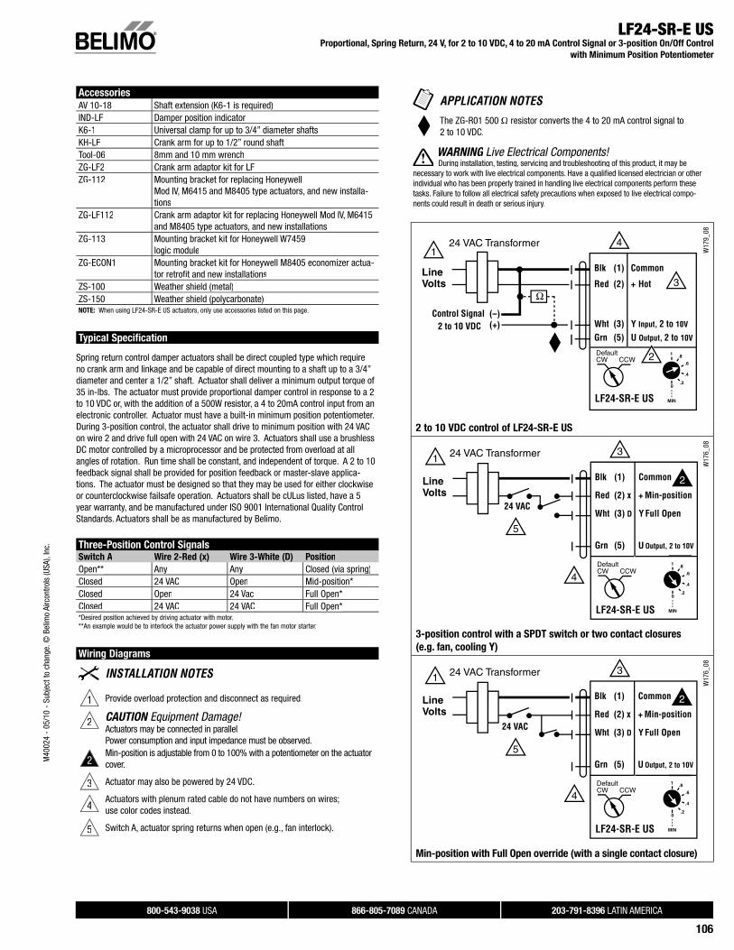
LF24-SR-E US Proportional, Spring Return, 24 V, for 2 to 10 VDC, 4 to 20 mA Control Signal or 3-position On/Off Control
with Minimum Position Potentiometer
Technical Data LF24-SR-E US
Power supply 24 VAC ± 20% 50/60 Hz24 VDC ± 10%
Power consumptionrunning 2.5 Wholding 1 W
Transformer sizing 5 VA (class 2 power source)Electrical connection 3 ft, plenum rated cable
1/2” conduit connector Overload protection electronic throughout 0 to 95° rotationControl signal Y 0 to 10 VDC, 0 to 20 mA,
or 24 VAC for 3-position on/off controlInput impedance 100 kΩOperating range Y 2 to 10 VDC, 4 to 20mA between 0% and 100%Feedback output U 2 to 10 VDC (max. 0.7 mA) for 95°Angle of rotation max. 95°, adjust. with mechanical stopTorque 35 in-lb [4 Nm] Override function Minimum, Open, Closed via spring
Min-position adjusts on actuator cover between 0 and 100% (scaled 0 to 1)
Direction of rotationspring reversible with cw/ccw mountingmotor reversible with built-in switch
Position indication visual indicator, 0° to 95°(0° is spring return position)
Running time motor 150 sec constant, independent of load(nominal) spring < 25 sec @-4°F to 122°F [-20°C to 50°C]
< 60 sec @-22°F [-30°C]Humidity 5 to 95% RH non-condensingAmbient temperature -22°F to 122°F [-30°C to 50°C]Storage temperature -40°F to 176°F [-40°C to 80°C]Housing NEMA type 2 /IP54Housing material zinc coated metalAgency listings cULus acc. to UL 873 and
CAN/CSA C22.2 No. 24-93Noise level (max) running < 30 db (A)
spring return 62 dB (A)Servicing maintenance freeQuality standard ISO 9001Weight 3.2 lbs (1.45 kg)
M40
024
- 05
/10
- Su
bjec
t to
chan
ge. ©
Bel
imo
Airc
ontro
ls (U
SA),
Inc.
800-543-9038 USA 866-805-7089 CANADA 203-791-8396 LATIN AMERICA
112
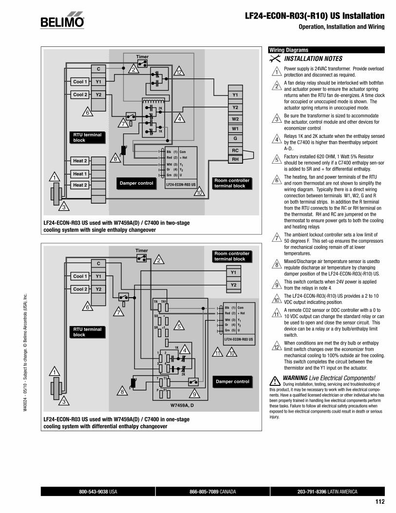
LF24-ECON-R03(-R10) US InstallationOperation, Installation and Wiring
W21
6
LF24-ECON-R03 US used with W7459A(D) / C7400 in two-stage
cooling system with single enthalpy changeover
LF24-ECON-R03 US used with W7459A(D) / C7400 in one-stage
cooling system with differential enthalpy changeover
Wiring Diagrams
1Power supply is 24VAC transformer. Provide overloadprotection and disconnect as required.
2A fan delay relay should be interlocked with both fan and actuator power to ensure the actuator spring returns when the RTU fan de-energizes. A time clock for occupied or unoccupied mode is shown. The actuator spring returns in unoccupied mode.
3Be sure the transformer is sized to accommodate the actuator, control module and other devices foreconomizer control.
4Relays 1K and 2K actuate when the enthalpy sensedby the C7400 is higher than the enthalpy setpointA-D..
5Factory installed 620 OHM, 1 Watt 5% Resistor should be removed only if a C7400 enthalpy sen- soris added to SR and + for differential enthalpy.
6The heating, fan and power terminals of the RTU and room thermostat are not shown to simplify the wiring diagram. Typically there is a direct wiring connection between terminals W1, W2, G and R on both terminal strips. In addition the R terminal from the RTU connects to the RC or RH terminal onthe thermostat. RH and RC are jumpered on the thermostat to ensure power gets to both the coolingand heating relays.
7The ambient lockout controller sets a low limit of 50 degrees F. This set-up ensures the compressors for mechanical cooling remain off at lower temperatures.
8Mixed/Discharge air temperature sensor is used to regulate discharge air temperature by changing damper position of the LF24-ECON-R03(-R10) US.
9This switch contacts when 24V power is applied from the relays in note 4.
1011The LF24-ECON-R03(-R10) US provides a 2 to 10VDC output indicating position.
1111A remote CO2 sensor or DDC controller with a 0 to10 VDC output can change the standard relay or canbe used to open and close the sensor circuit. Thisdevice can be a relay or a dry bulb/enthalpy limit switch.
1211When conditions are met the dry bulb or enthalpylimit switch changes over the economizer frommechanical cooling to 100% outside air free cooling. This switch completes the circuit between thethermistor and the Y1 input on the actuator.
WARNING Live Electrical Components!G During installation, testing, servicing and troubleshooting of
this product, it may be necessary to work with live electrical compo-nents. Have a qualifi ed licensed electrician or other individual who hasbeen properly trained in handling live electrical components performthese tasks. Failure to follow all electrical safety precautions whenexposed to live electrical components could result in death or seriousinjury.
M40
024
- 05
/10
- Su
bjec
t to
chan
ge. ©
Bel
imo
Airc
ontro
ls (U
SA),
Inc.
800-543-9038 USA 866-805-7089 CANADA 203-791-8396 LATIN AMERICA
106
LF24-SR-E US Proportional, Spring Return, 24 V, for 2 to 10 VDC, 4 to 20 mA Control Signal or 3-position On/Off Control
with Minimum Position Potentiometer
Accessories
AV 10-18 Shaft extension (K6-1 is required)IND-LF Damper position indicator K6-1 Universal clamp for up to 3/4” diameter shaftsKH-LF Crank arm for up to 1/2” round shaftTool-06 8mm and 10 mm wrenchZG-LF2 Crank arm adaptor kit for LFZG-112 Mounting bracket for replacing Honeywell
Mod IV, M6415 and M8405 type actuators, and new installa-tions
ZG-LF112 Crank arm adaptor kit for replacing Honeywell Mod IV, M6415and M8405 type actuators, and new installations
ZG-113 Mounting bracket kit for Honeywell W7459 logic module
ZG-ECON1 Mounting bracket kit for Honeywell M8405 economizer actua-tor retrofi t and new installations
ZS-100 Weather shield (metal)ZS-150 Weather shield (polycarbonate)NOTE: When using LF24-SR-E US actuators, only use accessories listed on this page.
Typical Specification
Spring return control damper actuators shall be direct coupled type which requireno crank arm and linkage and be capable of direct mounting to a shaft up to a 3/4” diameter and center a 1/2” shaft. Actuator shall deliver a minimum output torque of35 in-lbs. The actuator must provide proportional damper control in response to a 2to 10 VDC or, with the addition of a 500W resistor, a 4 to 20mA control input from anelectronic controller. Actuator must have a built-in minimum position potentiometer. During 3-position control, the actuator shall drive to minimum position with 24 VACon wire 2 and drive full open with 24 VAC on wire 3. Actuators shall use a brushlessDC motor controlled by a microprocessor and be protected from overload at all angles of rotation. Run time shall be constant, and independent of torque. A 2 to 10feedback signal shall be provided for position feedback or master-slave applica-tions. The actuator must be designed so that they may be used for either clockwiseor counterclockwise failsafe operation. Actuators shall be cULus listed, have a 5year warranty, and be manufactured under ISO 9001 International Quality Control Standards. Actuators shall be as manufactured by Belimo.
Three-Position Control SignalsSwitch A Wire 2-Red (x) Wire 3-White (D) Position
Open** Any Any Closed (via spring)Closed 24 VAC Open Mid-position*Closed Open 24 Vac Full Open*Closed 24 VAC 24 VAC Full Open**Desired position achieved by driving actuator with motor.**An example would be to interlock the actuator power supply with the fan motor starter.
Wiring Diagrams
1 Provide overload protection and disconnect as required.
2 CAUTION Equipment Damage!Actuators may be connected in parallel.Power consumption and input impedance must be observed.
2Min-position is adjustable from 0 to 100% with a potentiometer on the actuatorcover.
3 Actuator may also be powered by 24 VDC.
4Actuators with plenum rated cable do not have numbers on wires;use color codes instead.
5 Switch A, actuator spring returns when open (e.g., fan interlock).
The ZG-R01 500 Ω resistor converts the 4 to 20 mA control signal to2 to 10 VDC.
WARNING Live Electrical Components!G During installation, testing, servicing and troubleshooting of this product, it may be
necessary to work with live electrical components. Have a qualifi ed licensed electrician or otherindividual who has been properly trained in handling live electrical components perform these tasks. Failure to follow all electrical safety precautions when exposed to live electrical compo-nents could result in death or serious injury.
W17
9_08
2 to 10 VDC control of LF24-SR-E US
W17
6_08
3-position control with a SPDT switch or two contact closures
(e.g. fan, cooling Y)
W17
6_08
Min-position with Full Open override (with a single contact closure)
M40
024
- 05
/10
- Su
bjec
t to
chan
ge. ©
Bel
imo
Airc
ontro
ls (U
SA),
Inc.
800-543-9038 USA 866-805-7089 CANADA 203-791-8396 LATIN AMERICA
107
LF24-SR-E US Operation
Application of the LF24-SR-E US with Minimum Position Potentiometer
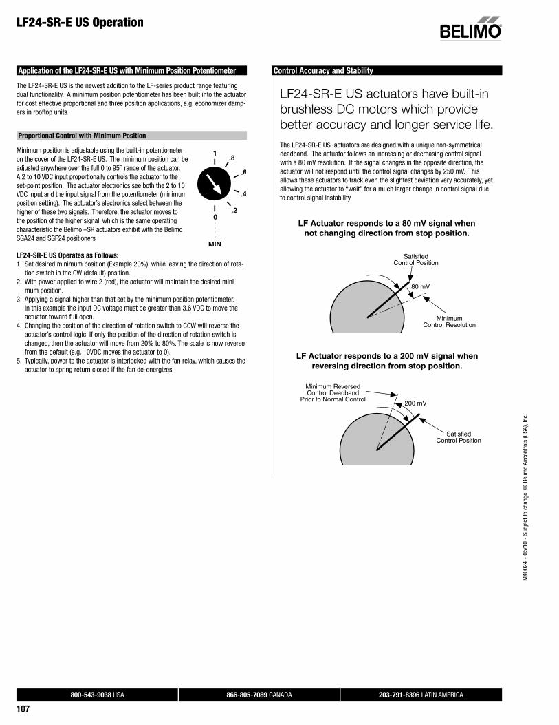
The LF24-SR-E US is the newest addition to the LF-series product range featuring dual functionality. A minimum position potentiometer has been built into the actuatorfor cost effective proportional and three position applications, e.g. economizer damp-ers in rooftop units.
Proportional Control with Minimum Position
Minimum position is adjustable using the built-in potentiometeron the cover of the LF24-SR-E US. The minimum position can be adjusted anywhere over the full 0 to 95° range of the actuator. AA 2 to 10 VDC input proportionally controls the actuator to the set-point position. The actuator electronics see both the 2 to 10VVDC input and the input signal from the potentiometer (minimum position setting). The actuator’s electronics select between the higher of these two signals. Therefore, the actuator moves tothe position of the higher signal, which is the same operating characteristic the Belimo –SR actuators exhibit with the Belimo SGA24 and SGF24 positioners.
LF24-SR-E US Operates as Follows:
1. Set desired minimum position (Example 20%), while leaving the direction of rota-tion switch in the CW (default) position.
2. With power applied to wire 2 (red), the actuator will maintain the desired mini-mum position.
3. Applying a signal higher than that set by the minimum position potentiometer. In this example the input DC voltage must be greater than 3.6 VDC to move theactuator toward full open.
4. Changing the position of the direction of rotation switch to CCW will reverse theactuator’s control logic. If only the position of the direction of rotation switch is changed, then the actuator will move from 20% to 80%. The scale is now reverse from the default (e.g. 10VDC moves the actuator to 0).
5. Typically, power to the actuator is interlocked with the fan relay, which causes theactuator to spring return closed if the fan de-energizes.
Control Accuracy and Stability
LF24-SR-E US actuators have built-in
brushless DC motors which provide
better accuracy and longer service life.
The LF24-SR-E US actuators are designed with a unique non-symmetricaldeadband. The actuator follows an increasing or decreasing control signalwith a 80 mV resolution. If the signal changes in the opposite direction, the actuator will not respond until the control signal changes by 250 mV. Thisallows these actuators to track even the slightest deviation very accurately, yet allowing the actuator to “wait” for a much larger change in control signal dueto control signal instability.
SatisfiedControl Position
MinimumControl Resolution
80 mV
LF Actuator responds to a 80 mV signal whennot changing direction from stop position.
SatisfiedControl Position
Minimum ReversedControl Deadband
Prior to Normal Control200 mV
LF Actuator responds to a 200 mV signal whenreversing direction from stop position.
.8
.6
.4
.20
1
MIN
M40
024
- 05
/10
- Su
bjec
t to
chan
ge. ©
Bel
imo
Airc
ontro
ls (U
SA),
Inc.

800-543-9038 USA 866-805-7089 CANADA 203-791-8396 LATIN AMERICA
113
Technical Data LF24-MFT(-S) US
Power supply 24 VAC, ± 20%, 50/60 Hz 24 VDC, ±10%
Power consumption running 2.5 Wholding 1.0 W
Transformer sizing 5 VA (Class 2 power source)Electrical connection(-S models have 2 cables)
3 ft, 18 GA, appliance cables1/2” conduit connector
Overload protection electronic throughout 0 to 95° rotationOperating range Y* 2 to 10 VDC
4 to 20 mA (w/500 Ω, 1/4 Ω resistor) ZG-R01Input impedance 100 kΩ for 2 to 10 VDC (0.1 mA)
500 Ω for 4 to 20 mA 1500 Ω for PWM, floating point andon/off control
Feedback output U* 2 to 10 VDC, 0.5 mA maxTorque min 35 in-lb (4 Nm)Direction of rotation* spring reversible with cw/ccw mounting
motor reversible with built-in switchMech. angle of rotation* max 95°, adjust with mechanical stopRunning time motor* 150 sec constant
spring <25 sec @-4°F to 122°F [-20°C to 50°C]<60 sec @-22°F [-30°C]
Angle of rotation adaptation* off (default)Override control* Min. (Min Position) = 0%
- ZS (Mid. Position) = 50%- Max. (Max. Position) = 100%
Position indication visual indicator, 0° to 95°Humidity 5 to 95% RH, non-condensingAmbient temperature -22 to 122° F (-30 to 50° C)Storage temperature -40 to 176° F (-40 to 80° C)Housing NEMA 2, IP54Housing material zinc coated metalNoise level less than 45 dB (A)Agency listings cULus acc. to UL 873 and
CAN/CSA C22.2 No. 24-93Quality standard ISO 9001Servicing maintenance freeWeight 6.0 lbs. (2.7 kg)* Variable when configured with MFT options
LF24-MFT-S US
Auxiliary switches 1 x SPDT 3A (0.5A) @ 250 VAC, UL approvedadjustable 0° to 95° (double insulated)
• Torque min. 35 in-lb
• Control 2 to 10 VDC (DEFAULT)
• Feedback 2 to 10 VDC (DEFAULT)
ApplicationFor proportional modulation of dampers and control valves in HVAC systems. The LF24-MFT US provides mechanical spring return operation for reliable fail-safeapplication.
Default/ConfigurationDefault parameters for 2 to 10 VDC applications of the LF24-MFT US actuator areassigned during manufacturing. If required, custom versions of the actuator can be ordered. The parameters noted in the Technical Data table are variable.
These parameters can be changed by three means:• Pre-set configurations from Belimo• Custom configurations from Belimo • Configurations set by the customer using the MFT PC tool software application.
OperationThe LF24-MFT US actuator provides 95° of rotation and is provided with a graduatedposition indicator showing 0° to 95°. The actuator will synchronize the 0° mechanical stop or the damper or valves mechanical stop and use this point for its zero position during normal control operations.
The actuator uses a brushless DC motor which is controlled by an Application Specific Integrated Circuit (ASIC) and a microprocessor. The microprocessor provides theintelligence to the ASIC to provide a constant rotation rate and to know the actuator’sexact position. The ASIC monitors and controls the brushless DC motor’s rotation andprovides a Digital Rotation Sensing (DRS) function to prevent damage to the actuatorin a stall condition. The position feedback signal is generated with out the need formechanical feedback potentiometers using DRS. The actuator may be stalled anywhere in its normal rotation without the need of mechanical end switches.
The LF24-MFT US is mounted directly to control shafts up to 3/4” diameter by means of its universal clamp and anti-rotation bracket. A crank arm and several mountingbrackets are available for damper applications where the actuator cannot be direct coupled to the damper shaft. The spring return system provides minimum specified torque to the application during a power interruption. The LF24-MFT US actuator isshipped in the zero position, compression against seats or gaskets for tight shut-off isaccomplished manually.
NOTE: Please see documentation on Multi-Function Technology.
Dimensions (Inches [mm])
0.39" [10]
7.67" [195]
3.66" [93]
1.93"[49]
6.10" [155]
3.15" [80]3.86"[98]
0.256" [6.5]0.98"[25]
4.92" [125]
0.79"[20]
0.5"[12.7]
0.71" [18]
0.74" [18.7]
2.24"[57]
3.23" [82]
0.25" [6.3]
Standard: 3/8" to 1/2"
3/8" to 7/16" Optional
1/2" to 3/4" w/K6-1 accessory
CCW
D059
LF24-MFT(-S) USProportional, Spring Return, Multi-Function Technology®
M40
024
- 05
/10
- Su
bjec
t to
chan
ge. ©
Bel
imo
Airc
ontro
ls (U
SA),
Inc.

800-543-9038 USA 866-805-7089 CANADA 203-791-8396 LATIN AMERICA
108
LF24-SR-E US Operation
Three-Position Control Using the LF24-SR-E US
By applying the LF24-SR override functionality and the new minimum positionpotentiometer, it is possible to achieve simple three-position control with the LF24-SR-E US.
1. Set desired minimum position (Example 20%), while leaving the direction ofrotation switch in the CW (default) position. The direction of rotation switch doesnot need to be changed for three-position control, because direction of rotation can be changed by fl ipping the actuator.
2. With 24 VAC power applied across wire 1 (black) and 2 (red), the actuator willmaintain minimum position.
3. Applying 24 VAC power across wire 1 (black) and 3 (white) overrides the minimumposition and moves the actuator to Full Open.
4. With no power applied to actuator, it will spring return (fail-safe) closed.5. Typically, power to the actuator is interlocked with the fan relay, which causes the
actuator to spring return closed if the fan de-energizes.
Features of the Belimo Three-Position Solution
The LF24-SR-E US will:
• Direct couple to the damper shaft between 3/8” and 3/4” diameter for reducedinstallation cost.
• Spring return in either CW or CCW direction depending on mounting orientation of the actuator. This feature eliminates the need to select a specifi c model withcorrect spring return direction.
• Spring returns in <25 seconds @ -4° to 122°F.• Increase minimum torque output to 35 in-lbs for 40% more torque than other
3-position actuator solutions.• Drive to the adjustable minimum position from either the fully Open or Closed
position using its brushless DC motor for improved reliability.Spring returns only during power loss.
• Drive full stroke in 150 seconds.• Output a 2 to 10 VDC signal for position feedback• Control a damper proportionally between minimum position and full open
(2 to 10 VDC input) for additional applications.• Have dual (3-position and proportional control) wiring diagrams on actuator label
for clear and easy wiring in the fi eld. • Consumes only 2.5 W driving to setpoint and 1 W to hold position, lower than
actuators using AC motor technology.
Replacing an M8405 Actuator
The three-position control functionality of the LF24-SR-E US allows direct replacement of a Honeywell M8405A foot mounted economizer actuator.
Mounting
For non-direct coupled applications use the ZG-ECON1 accessory kit, which includesthe KH-LF crank arm, ZG-112 bracket and logic module bracket (20477-00001). The ZG-112 aligns the plane of the crank arm with that of the Honeywell M8405A and has at least two mounting holes that match the M8405A foot pattern. The logicmodule bracket allows for attachment to the end of the LF24-SR-E US actuator. It provides for installation fl exibility to place the module where space is available.
Crank arm adaptor kit
– Includes bracket and KH-LF crank arm.– Bracket and crank arm for replacement
of Honeywell M8405 actuators.
ZG-112
Logic Module Bracket
KH-LF crank arm
Wiring
For proper control logic wiring always refer to the controller manufactures documentation. See the Product Documentation Standard Actuation and Accessories for proper three position wiring diagram Belimo wiring diagram, page 63.
M40
024
- 05
/10
- Su
bjec
t to
chan
ge. ©
Bel
imo
Airc
ontro
ls (U
SA),
Inc.

800-543-9038 USA 866-805-7089 CANADA 203-791-8396 LATIN AMERICA
109
• Torque min. 35 in-lb, for control of air dampers
• Built-in adjustable min-position
• Integrated mixed air PI-control
ApplicationFor proportional control of mixed air setpoint on economizer dampers in HVACsystems. Actuator sizing should be done in accordance with the damper manufacturer’s specifications.
The actuator is mounted directly to a damper shaft from 3/8” up to 1/2” in diameterby means of its universal clamp, 1/2” shaft centered at delivery. For shafts up to 3/4”use K6-1 accessory. A crank arm and several mounting brackets are available forapplications where the actuator cannot be direct coupled to the damper shaft.
The actuator operates in response to 3 kΩ or 10 kΩ thermistor, which allows theLF24-ECON... to retrofit or replace Honeywell® M7415 actuators.
OperationThe LF series actuators provide true spring return operation for reliable fail-safe application and positive close-off on air tight dampers. The spring return system provides constant torque to the damper with, and without, power applied to the actuator.
The LF series provides 95° of rotation and is provided with a graduated positionindicator showing 0 to 90°.
The LF24-ECON-R03 (-R10) US uses a brushless DC motor which is controlled by an Application Specific Integrated Circuit (ASIC) and a microprocessor. The microprocessor provides the intelligence to the ASIC to provide a constant rotation rate and to know the actuator’s exact position. The ASIC monitors and controls the brushless DC motor’s rotation and provides a digital rotation sensing function toprevent damage to the actuator in a stall condition. The actuator may be stalled anywhere in its normal rotation without the need of mechanical end switches. Powerconsumption is reduced in holding mode.
See wiring diagrams for LF24-ECON-R03 US for more details on 3-position control.
InstallationRefer to LF Section of the Standard Actuation and Accessories, ProductDocumentation.
Honeywell® is a trademark of Honeywell Inc.
Dimensions (Inches [mm])
0.39" [10]
7.67" [195]
3.66" [93]
1.93"[49]
6.10" [155]
3.15" [80]3.86"[98]
0.256" [6.5]0.98"[25]
4.92" [125]
0.79"[20]
0.5"[12.7]
0.71" [18]
0.74" [18.7]
2.24"[57]
3.23" [82]
0.25" [6.3]
Standard: 3/8" to 1/2"
3/8" to 7/16" Optional
1/2" to 3/4" w/K6-1 accessory
CCW
D059
LF24-ECON-R03(-R10) USProportional, Spring Return, 24 V, for Stand-Alone Economizer Damper Control Using
3 kΩ or 10 kΩ Mixed Air Sensor, Built-in Minimum Position Adjustment
Technical Data LF24-ECON-R03(-R10) US
Power supply 24 VAC ± 20% 50/60 Hz24 VDC ± 10%
Power consumption running 2.5 Wholding 1 W
Transformer sizing 5 VA (class 2 power source)Electrical connection 3 ft, plenum rated cable
1/2” conduit connector Overload protection electronic throughout 0 to 95° rotationControl signal, Y1(LF24-ECON-R03 US)
3 kΩ NTC Type 10 thermistor,3 kΩ @ 77°F (25°C)MA setpoint = 55°F
Input impedance 100 kΩFeedback output U 2 to 10 VDC (max. 0.7 mA) for 95°Angle of rotation max. 95°, adjust. with mechanical stopTorque 35 in-lb [4 Nm] Override function See override control table on opposite pageDirection of rotation spring reversible with cw/ccw mounting
motor reversible with built-in switchPosition indication Visual indicator, 0° to 95° scaled as 0 to 1
(0° is spring return position)Running time motor 95 sec constant, independent of load
spring < 25 sec @-4°F to 122°F [-20°C to 50°C]< 60 sec @-22°F [-30°C]
Humidity 5 to 95% RH non-condensingAmbient temperature -22°F to 122°F [-30°C to 50°C]Storage temperature -40°F to 176°F [-40°C to 80°C]Housing NEMA type 2 /IP54Housing material zinc coated metalAgency listings cULus acc. to UL 873 and
CAN/CSA C22.2 No. 24-93Noise level (max) running < 30 db (A)
spring return 62 dB (A)Servicing maintenance freeQuality standard ISO 9001Weight 3.2 lbs (1.45 kg)
LF24-ECON-R10 US
Control Signal, Y1 10 kΩ NTC Type 7 thermistor,10 kΩ @ 77°F (25°C)MA setpoint = 55°F
M40
024
- 05
/10
- Su
bjec
t to
chan
ge. ©
Bel
imo
Airc
ontro
ls (U
SA),
Inc.

800-543-9038 USA 866-805-7089 CANADA 203-791-8396 LATIN AMERICA
114
LF24-MFT(-S) USProportional, Spring Return, Multi-Function Technology®
W02
6
Auxiliary Switch LF24-MFT-S US
Sta
nd
ard
Wir
ing
W02
4_08
Overr
ide t
o Z
ero
Posit
ion
Overr
ide t
o 1
0V
Posit
ion
Overr
ide c
on
trol to
min
, mid
, ma
x, p
osit
ion
s
2 to 10 VDC control signal
Sta
nd
ard
Wir
ing
W02
5_08
Overr
ide t
o Z
ero
Po
sit
ion
Overr
ide t
o 2
0 m
A P
osit
ion
4 to 20 mA control signal
Wiring Diagrams
1 Provide overload protection and disconnect as required.
2 CAUTION Equipment Damage!Actuators may be connected in parallel if not mechanically mounted to the same shaft. Power consumption and input impedance must be observed.
3 Actuators may also be powered by 24 VDC.
4The Common connection from the actuator must be connected to the Hotconnection of the controller.
5For end position indication, interlock control, fan startup, etc., LF24-MFT-S US incorporates one built-in auxiliary switch: 1 x SPDT, 3A (0.5A) @250 VAC, UL Approved, adjustable 0° to 95°.
Meets cULus requirements without the need of an electrical ground con-nection.
The ZG-R01 500 Ω resistor may be used.
WARNING Live Electrical Components!G During installation, testing, servicing and troubleshooting of this product, it may be
necessary to work with live electrical components. Have a qualifi ed licensed electrician or other individual who has been properly trained in handling live electrical components perform thesetasks. Failure to follow all electrical safety precautions when exposed to live electrical compo-nents could result in death or serious injury.
M40
024
- 05
/10
- Su
bjec
t to
chan
ge. ©
Bel
imo
Airc
ontro
ls (U
SA),
Inc.

800-543-9038 USA 866-805-7089 CANADA 203-791-8396 LATIN AMERICA
110
Standard Economizer Mode Wiring
W20
3_08
Override
Override ControlWire Input Signal LF24-ECON... Position Application
Y1 24 VAC Drive closed (0%) Morning warm-up cycleY1 Common Drive open (100%) Smoke PurgeY1 Open wire Drive to min position Mechanical cooling in use, RTU
thermostat calls for heatY2 0 VDC to
10 VDCMin position of0% to 100%
Override potentiometer via aremote CO2 sensor/controlleror DDC controller
LF24-ECON-R03(-R10) USProportional, Spring Return, 24 V, for Stand-Alone Economizer Damper Control Using
3 kΩ or 10 kΩ Mixed Air Sensor, Built-in Minimum Position Adjustment
Accessories
AV 10-18 Shaft extension (K6-1 is required)IND-LF Damper position indicator K6-1 Universal clamp for up to 3/4” diameter shaftsKH-LF Crank arm for up to 1/2” round shaftTool-06 8mm and 10 mm wrenchZG-LF2 Crank arm adaptor kit for LF ZG-112 Mounting bracket for replacing Honeywell Mod IV, M7415 type
actuators, and new installationsZG-LF112 Crank arm adaptor kit for replacing Honeywell Mod IV, M7415
type actuators, and new installations20477-00001 Mounting bracket for Honeywell W7459 logic moduleZG-ECON1 Mounting bracket kit for Honeywell M7415 economizer
actuator retrofit and new installationsZS-100 Weather shield (metal)ZS-150 Weather shield (polycarbonate)NOTE: When using LF24-ECON-R03 (R10) US actuators,use accessories listed on this page.
Typical Specification
Spring return control damper actuators shall be direct coupled type which require no crank arm and linkage and be capable of direct mounting to a shaft up to a 3/4”diameter and center a 1/2” shaft. Actuator shall deliver a minimum output torque of35 in-lbs. The actuator must provide proportional damper control in response to a 3kΩ or 10 kΩ NTC thermistor, 55°F setpoint. Actuator must have a built-in minimumposition potentiometer. Actuator must have minimum position override via 0 to 10VDCon wire 4. Actuators shall use a brushless DC motor controlled by a microprocessor and be protected from overload at all angles of rotation. Run time shall be independent of torque load. A 2 to 10VDC feedback signal shall be provided for position feedback or master-slave applications. The actuator must be designed so that they may be used for either clock-wise or counterclockwise fail safe operation. Actuators shall be cULus listed, have a 5 year warranty, and be manufactured under ISO 9001 International Qual-ity Control Standards. Actuators shall be as manufactured by Belimo
Wiring Diagrams
1 Provide overload protection and disconnect as required.
2 Min-position is adjustable from 0 to 100% with a potentiometer on the actuatorcover.
3Actuators with plenum rated cable do not have numbers on wires;use color codes instead.
4 CW (default) indicates that motor drive starts at zero position.
5A relay or switch can spring return the actuator when the RTU fande-energizes, or if low ambient temperature is sensed.
6A standard relay can be used to close the sensor circuit to engage economizer mode, e.g. outside air changeover device like a dry bulb orenthalpy limit switch. Honeywell® logic module W7459A and enthalpysensor C7400 also provide terminals for this switching.
7A remote CO2 sensor or DDC controller with a 0 to 10 VDC output canchange the standard relay or can be used to open and close the sensorcircuit. This device can be a relay or a dry bulb/enthalpy limit switch.
8 Override control for Y2 only accepts 0 to 10 VDC override control.
WARNING Live Electrical Components!G During installation, testing, servicing and troubleshooting of this product, it may be
necessary to work with live electrical components. Have a qualifi ed licensed electrician or other individual who has been properly trained in handling live electrical components perform thesetasks. Failure to follow all electrical safety precautions when exposed to live electrical compo-nents could result in death or serious injury.
M40
024
- 05
/10
- Su
bjec
t to
chan
ge. ©
Bel
imo
Airc
ontro
ls (U
SA),
Inc.

800-543-9038 USA 866-805-7089 CANADA 203-791-8396 LATIN AMERICA
111
Wiring Diagram for Installation of the LF24-ECON-R03 US
W7459A(D) W7459A(D)
2
Blk (1) Common
Red (2) + Hot
Wht (3) Y1 3kΩ NTC
Or (4) Y2 Min-pos, 0-10 V
Grn (5) U Output, 2 to 10V
LF24-ECON-R03 US
Default CW CCW
0
.2.4 .6
.8
1
MIN
(1)
(2)
(3)
Field installed male connectors on actuators (provided with kit ZG-ECON1)
TR
TR124 V
ACSe
nsor
Min
Pos
T
T1
P
P1
TR1TR
+S0
+SR
5
51
43
T1T
P1P
Enthalpy Sensor connects to S & +
for differential enthalpy
Connects to Room Controller & RTU Terminal Blocks
Mixed/Discharge Air Temperature Sensor
Line Volts
W22
1
LF24-ECON-R03(-R10) USOperation, Installation and Wiring
Operation LF24-ECON-R03(-R10) US
The LF24-ECON-R03(-R10) US provides a direct coupling solution for RoofTop Unit(RTU) economizer dampers.
Control of Mixed Air in Typical Economizer Dampers
Occupied - Economizer Mode
The LF24-ECON-R03 (-R10) US enters Economizer Mode when either an externalrelay or controller (e.g. Honeywell® W7459A) completes the circuit between theactuator wire 3(Y1) and MA sensor. In this mode, the actuator moves proportionallyto maintain a MA set-point of 55°F(fi xed). A proportional band of 6°F modulates the actuator between 53 and 58°F. Also, a +/-1°F dead band eliminates hunting of the actuator, while maintaining suitable temperatures in the RTU mixed air chamber.
Occupied – Mechanical CH (Cooling or Heating) Mode
The LF24-ECON-R03(-R10) US enters Mechanical CH Mode when either an externalrelay or controller (e.g. Honeywell® W7459A) breaksthe circuit between the actuator wire 3(Y1) andMA sensor. In this mode, the actuator drives to minimum position. Minimum position can be set onbuilt-in potentiometer, or set remotely by sending a0 to 10 VDC signal to wire 4(Y2) via a SGA24 or DDCcontroller.
Unoccupied
RTU Economizer damper actuators typically interlock actuator supply power with RTU fan motor starter/relay. This set-up ensures that the actuator spring returns theeconomizer damper closed during periods when the ventilation air is not required.
MA Dry Bulb Temperature LF24-ECON... Position
< 53°F Min. position
53°F < MAT < 58°FModulates between Min. Positionand 100% open
> 58°F 100% open
0
.2.4 .6
.8
1
MIN
Mounting
Logic Module Bracket
H-LFKHrank armCr
ZG-112
Replacing an Honeywell® M7415 actuator
M7415
M7459
M40
024
- 05
/10
- Su
bjec
t to
chan
ge. ©
Bel
imo
Airc
ontro
ls (U
SA),
Inc.

800-543-9038 USA 866-805-7089 CANADA 203-791-8396 LATIN AMERICA
115
LF24-MFT(-S)-20 USProportional, Spring Return, 24 V, for 6 to 9 VDC
Output Power Supply 20 VDC Provides Power to Controllers
• Torque min. 35 in-lb
• Control 6 to 9 VDC (DEFAULT)
• Feedback 2 to 10 VDC (DEFAULT)
• 20 VDC power output
ApplicationFor proportional modulation of dampers and control valves in HVAC systems. TheLF24-MFT(-S)-20 US provides mechanical spring return operation for reliable fail-safeapplication.
Default/ConfigurationDefault parameters for 6 to 9 VDC applications of the LF24-MFT(-S)-20 US actuatorare assigned during manufacturing. If required, custom versions of the actuator can beordered. The parameters noted in the Technical Data table are variable.
These parameters can be changed by three means:
• Pre-set configurations from Belimo• Custom configurations from Belimo• Configurations set by the customer using the MFT PC tool software application.
OperationThe LF24-MFT(-S)-20 US actuator provides 95° of rotation and is provided with a graduated position indicator showing 0° to 95°. The actuator will synchronize the 0°mechanical stop or the damper or valves mechanical stop and use this point for itszero position during normal control operations.
The actuator uses a brushless DC motor which is controlled by an Application SpecificIntegrated Circuit (ASIC) and a microprocessor. The microprocessor provides theintelligence to the ASIC to provide a constant rotation rate and to know the actuator’sexact position. The ASIC monitors and controls the brushless DC motor’s rotation andprovides a Digital Rotation Sensing (DRS) function to prevent damage to the actuator ina stall condition. The position feedback signal is generated with out the need formechanical feedback potentiometers using DRS. The actuator may be stalled anywhere in its normal rotation without the need of mechanical end switches.
The LF24-MFT(-S)-20 US is mounted directly to control shafts up to 3/4” diameter bymeans of its universal clamp and anti-rotation bracket. A crank arm and severalmounting brackets are available for damper applications where the actuator cannot bedirect coupled to the damper shaft. The spring return system provides minimumspecified torque to the application during a power interruption. The LF24-MFT(-S)-20US actuator is shipped in the zero position, compression against seats or gaskets fortight shut-off is accomplished manually.
Dimensions (Inches [mm])
0.39" [10]
7.67" [195]
3.66" [93]
1.93"[49]
6.10" [155]
3.15" [80]3.86"[98]
0.256" [6.5]0.98"[25]
4.92" [125]
0.79"[20]
0.5"[12.7]
0.71" [18]
0.74" [18.7]
2.24"[57]
3.23" [82]
0.25" [6.3]
Standard: 3/8" to 1/2"
3/8" to 7/16" Optional
1/2" to 3/4" w/K6-1 accessory
CCWD0
59
Technical Data LF24-MFT(-S) -20 US
Power supply 24 VAC, ± 20%, 50/60 Hz 24 VDC, ±10%
Power consumption running 3 Wholding 1.5 W
Transformer sizing 6 VA (Class 2 power source)Electrical connection(-S models have 2 cables)
3 ft, 18 GA, appliance cable1/2” conduit connector
Overload protection electronic throughout 0 to 95° rotationOperating range Y* 6 to 9 VDC (Default), P-10005Input impedance 100 kΩ for 2 to 10 VDC (0.1 mA)
500 Ω for 4 to 20 mA 1500 Ω for PWM, floating point andon/off control
Feedback output U* 2 to 10 VDC, 0.5 mA maxTorque 35 in-lb (4 Nm)Direction of rotation* spring reversible with cw/ccw mounting
motor reversible with built-in switchAngle of rotation* max 95°, adjustable with mechanical stopMechanical angle of rotation* limited to 95°Running time motor* 150 sec constant
spring <25 sec @-4°F to 122°F [-20°C to 50°C]<60 sec @-22°F [-30°C]
Angle of rotation adaptation* off (default)Override control* Min. (Min Position) = 0%
- ZS (Mid. Position) = 50%- Max. (Max. Position) = 100%
Position indication visual indicator, 0° to 95°(0° is spring return position)
Humidity 5 to 95% RH, non-condensingAmbient temperature -22 to 122° F (-30 to 50° C)Storage temperature -40 to 176° F (-40 to 80° C)Housing NEMA 2, IP54Housing material zinc coated metalNoise level running < 30 db (A)
spring return 62 dB (A)Agency listings cULus acc. to UL 873 and
CAN/CSA C22.2 No. 24-93Quality standard ISO 9001Servicing maintenance freeWeight LF24-MFT-20 US 3.1 lbs (1.40 kg)
LF24-MFT-S-20 US 3.2 lbs (1.45 kg)* Variable when configured with MFT options
LF24-MFT-S-20 US
Auxiliary switches 1 x SPDT 3A (0.5A) @ 250 VAC, UL approvedadjustable 0° to 95° (double insulated)
M40
024
- 05
/10
- Su
bjec
t to
chan
ge. ©
Bel
imo
Airc
ontro
ls (U
SA),
Inc.

800-543-9038 USA 866-805-7089 CANADA 203-791-8396 LATIN AMERICA
116
LF24-MFT(-S)-20 USProportional, Spring Return, 24 V, for 6 to 9 VDC
Output Power Supply 20 VDC Provides Power to Controllers
Wiring Diagrams
1 Provide overload protection and disconnect as required.
2 CAUTION Equipment Damage!Actuators may be connected in parallel.Power consumption and input impedance must be observed.
2Actuators may be connected in parallel if not mechanically mounted to the same shaft. Power consumption and input impedance must be observed.
3 Actuator may also be powered by 24 VDC.
6For end position indication, interlock control, fan startup, etc., LF24-MFT(-S)-20 US incorporates one built-in auxiliary switch: 1 x SPDT, 3A (0.5A) @250 VAC, UL Approved, adjustable 0° to 95°.
A24 VAC: Black/Blue120 VAC: White240 VAC: White/BlackBelimo modulating actuators are 24 VAC/DC, if 120 or 240 is available anexternal transformer is required.
B Maximum of 2
C MP-52XX-500 models include internal SPDT auxiliary switch.
Meets cULus requirements without the need of an electrical ground con-nection.
WARNING Live Electrical Components!G During installation, testing, servicing and troubleshooting of this product, it may be
necessary to work with live electrical components. Have a qualifi ed licensed electrician or other individual who has been properly trained in handling live electrical components perform these tasks. Failure to follow all electrical safety precautions when exposed to live electrical compo-nents could result in death or serious injury.
3
24 VAC Transformer
Blk (1) Common
Red (2) + Hot
Wht (3) Y Input, 6 to 9V
Wht (4) Output +20 VDC
Wht (5) U Output 2 to 10V
Wht (6) Common +20 VDC
6 to 9 VDCControl Signal
(+)
Power to Controller
Feedback 2-10 VDC
Controller Common (–)
2
LF24-MFT(-S)-20 US
CW CCW
1
Line Volts
6 to 9 VDC control of LF24-MFT(-S)-20 US
W02
8_08
Auxiliary switch of LF24-MFT(-S)-20 US
W02
9_08
Multiple LF24-MFT(-S)-20 US actuators from one controller
W21
5_08
Typical Control Wiring for MP-52XX Series Actuators to Controllers
Requiring External 20 VDC Power Supply.
M40
024
- 05
/10
- Su
bjec
t to
chan
ge. ©
Bel
imo
Airc
ontro
ls (U
SA),
Inc.
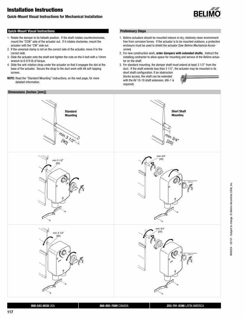
800-543-9038 USA 866-805-7089 CANADA 203-791-8396 LATIN AMERICA
117
Dimensions (Inches [mm])
min 3 1/2”[90]
S d dStandard
gMounting
min 3/4”[20]
S S fShort Shaft
gMounting
min 3 1/2”[90]
min 3/4”[20]
IND-LF Position Indicator(optional)
min 3 1/2”[90]
min 3/4”[20]
IND-LF Position Indicator(optional)
Installation InstructionsQuick-Mount Visual Instructions for Mechanical Installation
Quick-Mount Visual Instructions
1. Rotate the damper to its failsafe position. If the shaft rotates counterclockwise, mount the “CCW” side of the actuator out. If it rotates clockwise, mount theactuator with the “CW” side out.
2. If the universal clamp is not on the correct side of the actuator, move it to thecorrect side.
3. Slide the actuator onto the shaft and tighten the nuts on the V-bolt with a 10mmwrench to 6-8 ft-lb of torque.
4. Slide the anti-rotation strap under the actuator so that it engages the slot at the base of the actuator. Secure the strap to the duct work with #8 self-tappingscrews.
NOTE: Read the “Standard Mounting” instructions, on the next page, for moredetailed information.
Preliminary Steps
1. Belimo actuators should be mounted indoors in dry, relatively clean environmentfree from corrosive fumes. If the actuator is to be mounted outdoors, a protectiveenclosure must be used to shield the actuator (See Belimo Mechanical Acces-sories).s
2. For new construction work, order dampers with extended shafts. Instruct theinstalling contractor to allow space for mounting and service of the Belimo actua-tor on the shaft.
3. For standard mounting, the damper shaft must extend at least 3 1/2" from the duct. If the shaft extends less than 3 1/2", the actuator may be mounted in itsshort shaft confi guration. If an obstructionblocks access, the shaft can be extendedwith the AV 10-18 shaft extension. (K6-1 isrequired)
M40
024
- 05
/10
- Su
bjec
t to
chan
ge. ©
Bel
imo
Airc
ontro
ls (U
SA),
Inc.

800-543-9038 USA 866-805-7089 CANADA 203-791-8396 LATIN AMERICA
118
Mechanical Operation
The actuator is mounted directly to a damper shaft up to 1/2” in diameter by means of its universal clamp, or up to a 3/4” shaft with the optional K6-1 clamp. A crank arm and several mounting brackets are available for applications where the actuatorcannot be direct coupled to the damper shaft.
The LF series actuators provide true spring return operation for reliable fail-safeapplication and positive close-off on air tight dampers. The spring return systemprovides consistent torque to the damper with, and without, power applied to theactuator.
The LF series provides 95° of rotation and is provided with a graduated positionindicator showing 0 to 95°.
The LF…-S versions are provided with 1 built-in auxiliary switch. This SPDT switchis provided for safety interfacing or signaling, for example, for fan start-up. The switching function is adjustable between 0° and 95°.
Standard Mounting / Airtight Damper Procedure
1. See Figure B. Manually move the damper to the fail-safe position (a) (usuallyclosed). If the shaft rotated counterclockwise ( ), this is a CCW installation. )If the shaft rotated clockwise ( ), this is a CW installation. In a Left Hand)installation, the actuator side marked “CW” faces out, while in a CW installation,the side marked “CCW” faces out. All other steps are identical.
2. The actuator is usually shipped with the universal clamp mounted to the “CW”side of the actuator. To test for adequate shaft length, slide the actuator over the shaft with the side marked “CW” (or the “CCW” side if this is the side withthe clamp). If the shaft extends at least 1/8” through the clamp, mount the actuator as follows. If not, go to the Short Shaft Installation section.n
3. If the clamp is not on the correct side as determined in step #1, re-mount theclamp as follows. If it is on the correct side, proceed to step #5. Look at theuniversal clamp. If you are mounting the actuator with the “CCW” side out, position the clamp so that the pointer section of the tab is pointing to 0° (seeFigure C) and the spline pattern of the clamp mates with spline of the actuator. Slip the clamp over the spline. (Use the same procedure if the “CW” side is out.)
4. Lock the clamp to the actuator using the retaining clip.5. Verify that the damper is still in its full fail-safe position (a).6. Mount the spring return actuator to the shaft. Tighten the universal clamp,
finger tight only.7. Mount the anti-rotation strap at the base of the actuator. Do not tighten the
screws.8. Remove the screw from one end of the mounting bracket and pivot it away
from the actuator.9. Loosen the universal clamp and, making sure not to move the damper shaft,
rotate the actuator approximately 5° in the direction which would open thedamper.
10. Tighten the universal clamp to the shaft.11. Rotate the actuator to apply pressure to the damper seals (b) and re-engage
the anti-rotation strap (c).12. Tighten all fasteners.
Installation InstructionsMechanical Installation
min 3 1/2”[90]
FIGURE B – Standard Mounting (Dimensions in Inches [mm])
FIGURE C – Universal Clamp
M40
024
- 05
/10
- Su
bjec
t to
chan
ge. ©
Bel
imo
Airc
ontro
ls (U
SA),
Inc.

800-543-9038 USA 866-805-7089 CANADA 203-791-8396 LATIN AMERICA
119
Installation InstructionsMechanical Installation
Short Shaft Mounting with
IND-LF Position Indicator / Airtight Damper Procedure
If the shaft extends at least 3/4” from the duct, follow these steps:1. (See Figure D) Move damper blades to the fail-safe position (a).2. Determine the best orientation for the universal clamp on the back of the actuator.
The best location would be where you have the easiest access to the V bolt nutson the clamp.
3. Engage the clamp to the actuator as close as possible to the determined location.4. Lock the clamp to the actuator using the retainer clip.5. Mount the spring return actuator to the shaft. Tighten the universal clamp, fi nger
tight only.6. Mount the anti-rotation strap at the base of the actuator. Do not tighten the
screws.7. Remove the screw from one end of the mounting bracket and pivot it away from
the actuator.8. Loosen the universal clamp and, making sure not to move the damper shaft, rotate
the actuator approximately 5° in the direction which would open the damper.9. Verify that the damper is still in its full fail-safe position.10. Tighten the universal clamp to the shaft.11. Rotate the actuator to apply pressure to the damper seals (b) and re-engage the
anti-rotation strap (c).12. Tighten all fasteners.13. Use IND-LF accessory if position indication is needed.
Operational Information for
LF24-SR US and LF24-MFT… US Actuators
Initialization of the LF24-SR US and LF24-MFT… US
When power is applied, the internal microprocessor recognizes that the actuator is at its full fail-safe position and uses this position as the base for allof its position calculations. This procedure takes approximately 15 seconds. During this time you will see no response at the actuator. The microprocessorwill retain the initialized zero during short power failures of up to 25 seconds. When power is applied during this period, the actuator will return to normal operation and proceed to the position corresponding to the input signalprovided. For power failures over 25 seconds, the actuator will be at it fail-safe position and will go through the start up initialization again.
Motor position detection
Belimo brushless DC motors eliminate the need for potentiometers forpositioning. Inside the motor are three “Hall Effect” sensors. These sensors detect the spinning rotor and send pulses to the microprocessor which counts the pulses and calculates the position to within 1/3 of a revolution of the motor.
Overload protection
The LF, On/Off actuators are electronically protected against overload. The LF,On/Off actuators have an internal current limiter which maintains the current ata safe level which will not damage the actuator while providing adequate holdingtorque.
The LF24, modulating actuators (LF24-SR US, LF24-3 US, LF24-MFT US) areprotected against overload by digital technology located in the ASIC. The ASIC circuitry constantly monitors the rotation of the brushless DC motor inside theactuator and stops the pulsing to the motor when it senses a stall condition. Themotor remains energized and produces full rated torque during stall conditions. The actuator will try to move in the direction of the stall every 2 minutes, for aperiod of 32 minutes. After this, the actuator will try again every 2 hours.
min 3/4”[20]
IND-LF Position Indicator(optional)
FIGURE D – Standard Mounting (Dimensions in Inches [mm])
FIGURE C – Universal Clamp
M40
024
- 05
/10
- Su
bjec
t to
chan
ge. ©
Bel
imo
Airc
ontro
ls (U
SA),
Inc.

800-543-9038 USA 866-805-7089 CANADA 203-791-8396 LATIN AMERICA
120
Installation InstructionsMechanical Installation
Mechanical Angle of Rotation Limiting
The LF actuators are provided with an adjustable stop to limit the rotation of theactuator. This function works in conjunction with the universal clamp or the optional position indicator. The adjustable stop is needed when rotation of less than 95° is required. The LF actuator can be indefi nitely stalled, in any position, without harmingthe actuator.
Using the Universal Clamp
1. Loosen the end stop fastening screw using a #2 Phillips screwdriver. 2. Move the stop block so the bottom edge of the block lines up with the number
corresponding to the desired degrees of rotation. (example: 45 degrees of rotation= .5)
3. Lock the block in place with the fastening screw.4. Check the actuator for proper rotation.
Using the IND-LF Position Indicator with Adjustable Stop
NOTE: preferred method if short shaft mounting is used.
1. With the actuator in its fail-safe position, place the IND-LF Position Indicator so thatit points to the 0 degree position.
2. Loosen the end stop fastening screw using a #2 Phillips screwdriver.3. Move the stop block so the bottom edge of the block lines up with the number
corresponding to the desired degrees of rotation (example: 45 degrees of rotation =.5).
4. Lock the block in place with the fastening screw.5. Check the actuator for proper rotation.
Direction of Rotation Switch
LF24-3(-S) US and LF24-SR(-S) US actuators have a direction of rotation switch on the cover labeled “CW-CCW”. Switch position indicates start point. For the LF24-SR, with the switch in position “CW”, the actuator rotates clockwise with a decrease involtage or current. With the switch in position “CCW”, the actuator rotates counter-clockwise with a decrease in voltage or current. The LF24-3(-S) US and LF24-SR(-S) US actuators rotate clockwise when the switch is in the “CW” position and power is applied to wire #3. When power is applied towire #4 the actuator rotates counter clockwise.
Rotating the direction of rotation switch to “CCW” reverses the control logic.During checkout, the switch position can be temporarily reversed and the actuator will reverse its direction. This allows the technician a fast and easy way to check the actuator operation without having to switch wires or change settings on thecontroller. When the check-out is complete, make sure the switch is placed back to its original position.
Control Accuracy and Stability
LF24-SR US actuators have built-in
brushless DC motors which provide
better accuracy and longer service life.
The LF24-SR US actuators are designed with a unique non-symmetricaldeadband. The actuator follows an increasing or decreasing control signalwith a 160 mV resolution. If the signal changes in the opposite direction, the actuator will not respond until the control signal changes by 200 mV. This allows these actuators to track even the slightest deviation very accurately, yet allowing the actuator to “wait” for a much larger change in control signal dueto control signal instability.
The LF24-MFT(-S) US control accuracy and stability can be found in the MFTtechnical documentation.
M40
024
- 05
/10
- Su
bjec
t to
chan
ge. ©
Bel
imo
Airc
ontro
ls (U
SA),
Inc.

800-543-9038 USA 866-805-7089 CANADA 203-791-8396 LATIN AMERICA
121
Installation InstructionsAuxiliary Switches and Non-Direct Mounting Methods
Auxiliary Switches
The …-S model actuators are equipped with an adjustable auxiliary switch used to indicate damper position or to interface additional controls or equipment. Switchingpositions can be set over the full 0 to 95° rotation simply by setting a switch on theactuator.
1. Set desired switch position.(Example 60%)
2. As the actuator rotates, the switchindicator moves from .6 (60%) toward 0(0%). When the indicator passes 0 the switch contact between S1 and S2 is broken and the contact between S1 andS3 is made.
Switch RatingVoltage Resistive load Inductive load
120 VAC 3 A 1.03 A250 VAC 3 A 0.5 A
.8
.6
.4
.20
1
S1S2
S3
S1S2
S3
Non-Direct Mounting Methods
KH-LF Crank armIncluding Retaining Ring
KH-LF
For round shafts up to 1/2”
ZG-LF112 Crank arm Adaptor Kit
ZG-112
KH-LF crank arm
ZG-LF2 Crank arm Adaptor Kit
( o supp ed )(not supplied with kit)
KG6 ball joint and universal crank arm(not included)
KG6 ball joint(not included)
KH-LF crank arm
M40
024
- 05
/10
- Su
bjec
t to
chan
ge. ©
Bel
imo
Airc
ontro
ls (U
SA),
Inc.
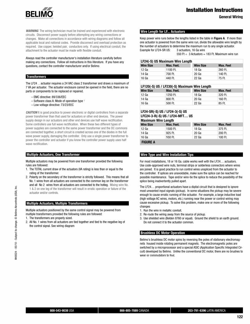
800-543-9038 USA 866-805-7089 CANADA 203-791-8396 LATIN AMERICA
122
Installation InstructionsGeneral Wiring
WARNING The wiring technician must be trained and experienced with electronic circuits. Disconnect power supply before attempting any wiring connections or changes. Make all connections in accordance with wiring diagrams and follow all applicable local and national codes. Provide disconnect and overload protection as required. Use copper, twisted pair, conductors only. If using electrical conduit, the attachment to the actuator must be made with fl exible conduit.
Always read the controller manufacturer's installation literature carefully before making any connections. Follow all instructions in this literature. If you have any questions, contact the controller manufacturer and/or Belimo.
Transformers
The LF24 . . actuator requires a 24 VAC class 2 transformer and draws a maximum of7 VA per actuator. The actuator enclosure cannot be opened in the fi eld, there are noparts or components to be replaced or repaired.
– EMC directive: 89/336/EEC – Software class A: Mode of operation type 1 – Low voltage directive: 73/23/EEC
CAUTION It is good practice to power electronic or digital controllers from a separate power transformer than that used for actuators or other end devices. The power supply design in our actuators and other end devices use half wave rectifi cation. Some controllers use full wave rectifi cation. When these two different types of power supplies are connected to the same power transformer and the DC commons are connected together, a short circuit is created across one of the diodes in the full wave power supply, damaging the controller. Only use a single power transformer to power the controller and actuator if you know the controller power supply uses half wave rectifi cation.
Multiple Actuators, One Transformer
Multiple actuators may be powered from one transformer provided the following rules are followed:1. The TOTAL current draw of the actuators (VA rating) is less than or equal to the
rating of the transformer.2. Polarity on the secondary of the transformer is strictly followed. This means that all
No. 1 wires from all actuators are connected to the common leg on the transformer and all No 2 wires from all actuators are connected to the hotleg. Mixing wire No. 1 & 2 on one leg of the transformer will result in erratic operation or failure of the actuator and/or controls.
Multiple Actuators, Multiple Transformers
Multiple actuators positioned by the same control signal may be powered frommultiple transformers provided the following rules are followed:1. The transformers are properly sized.2. All No. 1 wires from all actuators are tied together and tied to the negative leg of
the control signal. See wiring diagram.
Wire Length for LF... Actuators
Keep power wire runs below the lengths listed in the table in Figure A. If more thanone actuator is powered from the same wire run, divide the allowable wire length by the number of actuators to determine the maximum run to any single actuator. Example for LF24-SR US: 3 actuators, 16 Ga wire 550 Ft ÷ 3 Actuators = 183 Ft. Maximum wire run
LF24(-S) US Maximum Wire LengthWire Size Max. Feet. Wire Size Max. Feet
12 Ga 1100 Ft. 18 Ga 260 Ft.14 Ga 700 Ft. 20 Ga 140 Ft. 16 Ga 440 Ft. 22 Ga 75 Ft.
LF120(-S) US / LF230(-S) Maximum Wire LengthWire Size Max. Feet. Wire Size Max. Feet
12 Ga 1250 Ft. 18 Ga 320 Ft.14 Ga 800 Ft. 20 Ga 160 Ft. 16 Ga 500 Ft. 22 Ga 85 Ft.
LF24-SR(-S) US / LF24-3(-S) US
LFC24-3-R(-S) US / LF24-MFT… US
Maximum Wire LengthWire Size Max. Feet. Wire Size Max. Feet
12 Ga 1500 Ft. 18 Ga 375 Ft.14 Ga 925 Ft. 20 Ga 200 Ft. 16 Ga 550 Ft. 22 Ga 100 Ft.
FIGURE A
Wire Type and Wire Installation Tips
For most installations, 18 or 16 Ga. cable works well with the LF24… actuators. Use code-approved wire nuts, terminal strips or solderless connectors where wiresare joined. It is good practice to run control wires unspliced from the actuator tothe controller. If splices are unavoidable, make sure the splice can be reached forpossible maintenance. Tape and/or wire-tie the splice to reduce the possibility of thesplice being inadvertently pulled apart.
The LF24… proportional actuators have a digital circuit that is designed to ignoremost unwanted input signals (pickup). In some situations the pickup may be severeenough to cause erratic running of the actuator. For example, a large inductive load(high voltage AC wires, motors, etc.) running near the power or control wiring may cause excessive pickup. To solve this problem, make one or more of the followingchanges:1. Run the wire in metallic conduit.2. Re-route the wiring away from the source of pickup.3. Use shielded wire (Belden 8760 or equal). Ground the shield to an earth ground.
Do not connect it to the actuator common.
Brushless DC Motor Operation
Belimo's brushless DC motor spins by reversing the poles of stationary electromag-nets housed inside rotating permanent magnets. The electromagnetic poles are switched by a microprocessor and a special ASIC (Application Specifi c Integrated Cir-cuit) developed by Belimo. Unlike the conventional DC motor, there are no brushes towear or commutators to foul.
M40
024
- 05
/10
- Su
bjec
t to
chan
ge. ©
Bel
imo
Airc
ontro
ls (U
SA),
Inc.

800-543-9038 USA 866-805-7089 CANADA 203-791-8396 LATIN AMERICA
123
Startup and CheckoutInstructions For LF24-SR (-S) US and LF24-MFT…US + P100
LF24-SR (-S) US and LF24-MFT…US + P100 Electrical Check-Out Procedure
STEP Procedure Expected ResponseGives Expected Response
Go To Step…
Does Not Give
Expected Response
Go To Step…
1. Remove power to reset actuator.Re-apply power.Apply control signal to actuator.
Actuator will move to its “Control Signal” position.
Actuator operates properly Step 8. No response at all Step 2.
Operation is reversed Step 3.
Does not drive toward "Control Signal Position" Step 4.
2. Check power wiring.Correct any problems.See Note 1.
Power supply rating should be the total power requirement of the actuator(s). Minimum voltage of 19.2 VAC or 21.6 VDC.
Power wiring corrected, actuator begins to drive Step 1.
Power wiring corrected, actuator still does not drive Step 4.
3. Turn reversing switch to the correct position. Make sure the switch isturned all the way left or right.
Actuator will move to its “Control Signal” position.
Actuator operates properly Step 8. Does not drive toward “Control Signal Position” Step 4.
4. Make sure the control signal positive (+) is connected to Wire No 3 and control signal negative (-) is connected to wire No. 1. Most control problems are caused by reversing these two wires. Verify that the reversing switch is all the way CCW or CW.
Drives to “Control Signal” position Actuator operates properly Step 8. Step 5.
5. Check input signal with a digital volt meter (DVM). Make sure the input is within the range of the actuator. ForLF24-SR US this is 2 to 10 VDC or 4 to 20 mA. Note: The input signal mustbe above the 2 VDC or 4 mA to have the actuator move.
Input voltage or current should be ±1% of what controller's adjustment or programming indicate.
Controller output (actuator input) is correct. Input Polarity CorrectStep 6.
Reprogram, adjust repair or replacecontroller as needed Step 1.
6. Loosen the nuts on the V-bolt andmove the damper by hand from fully closed to fully open.
Damper will go from fully closed to fully open.
Damper moves properly Step 7. Find cause of damper jam and repair. Move damper back to the fully closed position and tighten the nuts Step 1.
7. Check damper torque requirement. Torque requirement is actuator’s minimum torque.
Defective Actuator.Replace Actuator. - See Note 2.
Recalculate actuator requirement andcorrect installation.
8. Actuator works properly. Test controller by following controller manufacturer'sinstructions.
NOTE 1 Check that the transformer(s) are sized properly.• If a common transformer is used, make sure that polarity is observed on the secondary. This means connect all No. 1 wires to one leg of the transformer and all
No. 2 wires to the other leg of the transformer. • If multiple transformers are used with one control signal, make sure all No. 1 wires are tied together and tied to control signal negative (-).• Controllers and actuators must have separate 24 VAC/VDC power sources.
NOTE 2 If failure occurs within 5 years from original installation date, notify Belimo and give details of the application.
M40
024
- 05
/10
- Su
bjec
t to
chan
ge. ©
Bel
imo
Airc
ontro
ls (U
SA),
Inc.