Embed Size (px)
Citation preview

LEXUS IS 250/350 Convertible 2010 - SUSPENSION KIT Preparation
Page 1 of 22 pages PPOIssue: B 10/09/2014
Part Number: PTR07-53100 (Springs) PTR13-53098 (Rr Shocks) PTR13-53080 (RF Shock)
PTR13-53081 (LF Shock) Kit Contents (Springs) Item # Quantity Reqd. Description 1 2 Front Springs 2 2 Rear Springs 3 1 Hardware Bag
Kit Contents (Rear Shock Absorbers) Item # Quantity Reqd. Description 1 1 Shock Absorber 2 3
Kit Contents (Each Front Shock Absorber) Item # Quantity Reqd. Description 1 1 Shock Absorber 2 1 Hardware Bag 3
Hardware Bag Contents (Springs) Item # Quantity Reqd. Description 1 2 Front Shock Absorber Locking
Nuts 2 1 Installation Instructions 3
Hardware Bag Contents (Each Front Shock) Item # Quantity Reqd. Description 1 1 Locking Shock Absorber Nut 2 1 Spring Seat 3 1 Shock Absorber Collet (spacer)
Additional Items Required For Installation Item # Quantity Reqd. Description 1
Conflicts None
General Applicability IS 250 & IS 350 Convertible only
Recommended Sequence of Application Item # Accessory 1 F-Sport Performance Package 2 F-Sport Exhaust 3 F-Sport Rear Brakes
*Mandatory
Recommended Tools Personal & Vehicle Protection
Notes
Fender Covers Safety Glasses
Special Tools Notes Spring Compressor Alignment Machine Tru-Line or comparable
Installation Tools Notes Torque Wrench 3/8” & ½” drive Ratchet 3/8” & ½” drive Wrenches 19mm Sockets 10, 14, 17, 19mm Snap-On QXXM19A or QXOM19A Hexagon Wrench 6 mm Nylon Pry Tool
Special Chemicals Notes
Vehicle Service Parts (may be required for reassembly) Item # Quantity Reqd. Description 1 2 90467-12069 white trunk trim
clip 1 3 90467-10167 blue trunk trim
clip 1 7 90467-08186-C0 black trunk
trim clip
Legend STOP: Damage to the vehicle may occur. Do not
proceed until process has been complied with.
OPERATOR SAFETY: Use caution to avoid risk of injury.
CAUTION: A process that must be carefully observed in order to reduce the risk of damage to the accessory/vehicle and to ensure a quality installation.
TOOLS & EQUIPMENT: Used in Figures calls out the specific tools and equipment recommended for this process.
REVISION MARK: This mark highlights a change in installation with respect to previous issue. SAFETY TORQUE: This mark indicates that torque is related to safety.

LEXUS IS 250/350 Convertible 2010 - SUSPENSION KIT Procedure
Page 2 of 22 pages PPOIssue: B 10/09/2014
Care must be taken when installing this accessory to ensure damage does not occur to the vehicle. The installation of this accessory should follow approved guidelines to ensure a quality installation. These guidelines can be found in the "Accessory Installation Practices" document. This document covers such items as:-
Vehicle Protection (use of covers and blankets, cleaning chemicals, etc.). Safety (eye protection, rechecking torque procedure, etc.). Vehicle Disassembly/Reassembly (panel removal, part storage, etc.). Electrical Component Disassembly/Reassembly (battery disconnection, connector removal, etc.).
Please see your Lexus dealer for a copy of this document.
1. Remove the Rear Shock Absorber/Spring
Assemblies.
(a) Remove the spring and shock absorber
assembly access covers. The passenger’s
side is shown (Fig. 1-1).
NOTE: The roof must be in the closed position.
(b) Remove the 3 nuts on the upper side of the
rear shock absorber assembly (Fig. 1-2).
(c) Raise the vehicle and remove the rear
wheels.
CAUTION: Do not use an impact wrench on
wheel locks (if equipped).
Nylon pry tool
Fig. 1-1
14mm socket & ratchet
Fig. 1-2

LEXUS IS 250/350 Convertible 2010 - SUSPENSION KIT Procedure
Page 3 of 22 pages PPOIssue: B 10/09/2014
(d) Loosen (do not remove) the lower rear No. 2
suspension arm nut (A, Fig. 1-3).
CAUTION: Do not remove the nut.
(e) Remove bolt B and the nut (Fig. 1-3).
(f) Disconnect the stabilizer link assembly and
height control sensor link bracket from the
rear No. 2 suspension arm assembly (Fig. 1-
3).
(g) Remove bolt C and the nut (Fig. 1-3).
CAUTION: The nut has a locking feature.
Remove the bolt and nut by turning the BOLT
while the nut is held in place.
(h) Remove bolt D and the nut on the axle carrier
side and lower the rear No. 2 suspension arm
assembly from the knuckle assembly (Fig. 1-
3).
CAUTION: The nut has a locking feature.
Remove the bolt and nut by turning the BOLT
while the nut is held in place.
(i) Remove two fender liner nuts to access the
rear shock absorber assembly.
(j) Remove the 2 bolts and the rear shock
absorber assembly from the body (Fig. 1-4).
Retain the bolts for reassembly.
(k) Remove the spring from shock absorber
assembly.
(1) Use a spring compressor to compress the
rear coil spring until the tension is
removed from the shock absorber
assembly.
19mm socket & wrench and ratchet
Fig. 1-3
19mm socket & ratchet
Fig. 1-4

LEXUS IS 250/350 Convertible 2010 - SUSPENSION KIT Procedure
Page 4 of 22 pages PPOIssue: B 10/09/2014
(2) Remove the upper shock absorber nut. If
the shaft spins with the nut, hold the rod
of the rear shock absorber assembly with
a 6mm hexagon wrench (Fig. 4-5).
(3) Note the order and position of the
washer, bushings and jounce bumper for
reassembly.
(l) Discard the OE coil spring.
(m) Repeat Step 1 on the other side of the
vehicle.
2. Replace the Rear Springs and Shock Absorbers.
(a) Place a spring seat over the shock absorber
body and onto the snap ring.
NOTE: A recessed ring is machined into the
spring seat which is designed to fit over the
shock absorber body snap ring.
(b) Transfer the rear lower coil spring insulator
to the new spring seat (Fig. 2-1).
17mm socket, ratchet & 6mm hex wrench
Fig. 1-5
Fig. 2-1

LEXUS IS 250/350 Convertible 2010 - SUSPENSION KIT Procedure
Page 5 of 22 pages PPOIssue: B 10/09/2014
(c) Fit the rear coil spring end into the recessed
part of the rear lower shock absorber seat
(Fig. 2-2).
(d) Turn the spring seat so that the lower end of
the coil lines up with the shock absorber
mount eye (Fig. 2-2).
(e) Reassemble the shock absorber/spring
assembly as shown below (Fig. 2-3).
Fig. 2-2
Fig. 2-3
LEXUS IS 250/350 Convertible 2010 - SUSPENSION KIT Procedure
Page 6 of 22 pages PPOIssue: B 10/09/2014
(f) Ensure the collet or spacer included with the
shock absorber is fitted over the shock
absorber shaft first.
(g) Ensure the cushions and washer (lip turned
up) are assembled in the correct direction and
order (Fig. 2-4).
(h) Torque the new shock absorber shaft lock nut
(Fig. 2-5).
Torque: 18 N·m (184 kgf·cm, 13 ft·lbf)
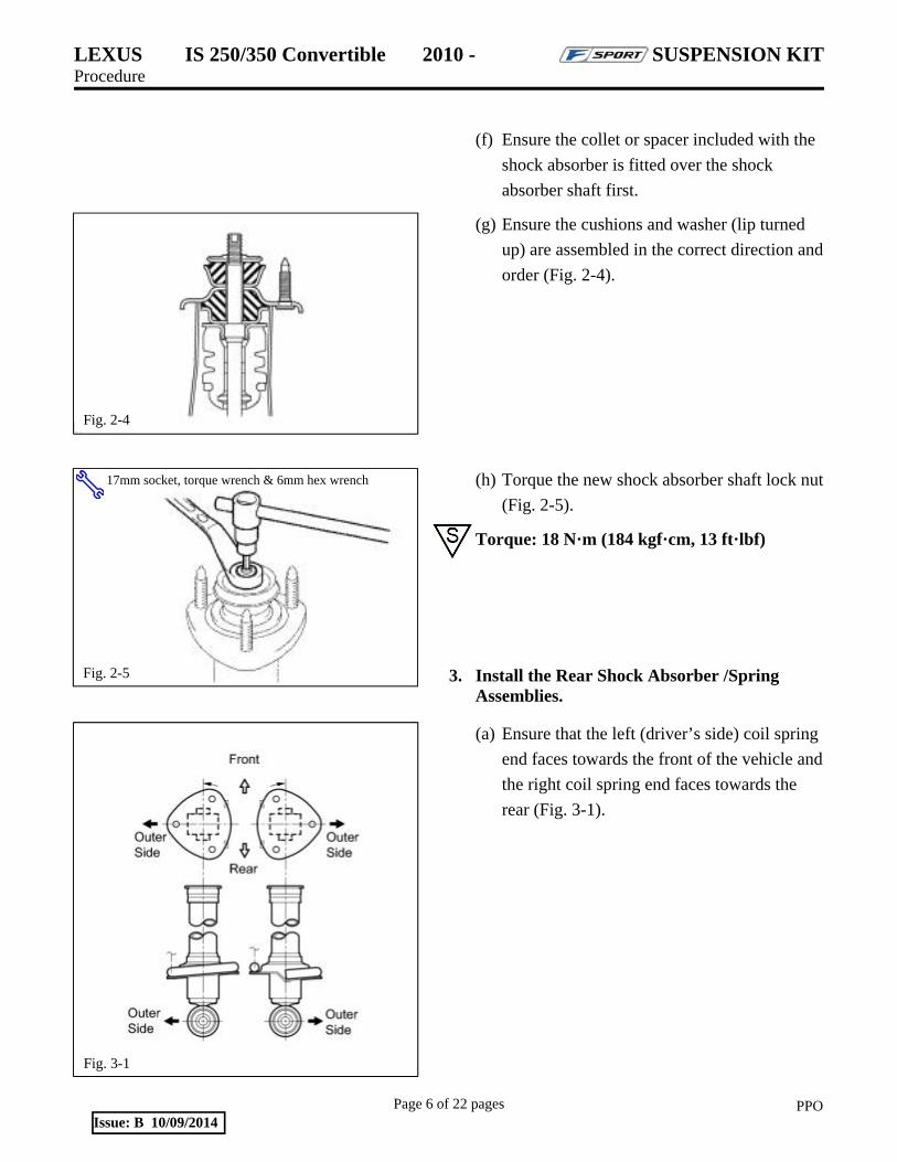
3. Install the Rear Shock Absorber /Spring Assemblies.
(a) Ensure that the left (driver’s side) coil spring
end faces towards the front of the vehicle and
the right coil spring end faces towards the
rear (Fig. 3-1).
Fig. 2-4
17mm socket, torque wrench & 6mm hex wrench
Fig. 2-5
Fig. 3-1
LEXUS IS 250/350 Convertible 2010 - SUSPENSION KIT Procedure
Page 7 of 22 pages PPOIssue: B 10/09/2014
(b) Temporarily install the rear shock absorber
assembly with the 2 bolts removed in Step
1(j) (Fig. 3-2).
NOTE: Leave the bolts loose.
(c) Install the 3 nuts on the upper side of the rear
shock absorber assembly (Fig. 3-3).
Torque: 74 N·m (755 kgf·cm, 55 ft·lbf)
(d) Install the spring and shock absorber
assembly trim covers.
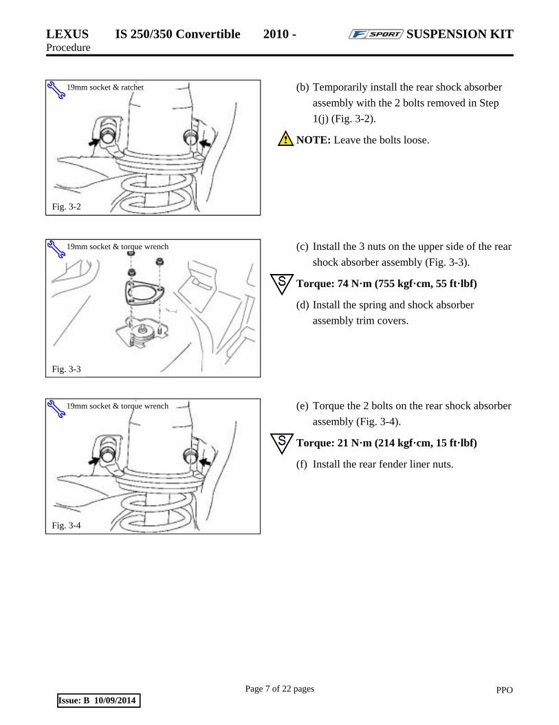
(e) Torque the 2 bolts on the rear shock absorber
assembly (Fig. 3-4).
Torque: 21 N·m (214 kgf·cm, 15 ft·lbf)
(f) Install the rear fender liner nuts.
19mm socket & ratchet
Fig. 3-2
19mm socket & torque wrench
Fig. 3-4
19mm socket & torque wrench
Fig. 3-3

LEXUS IS 250/350 Convertible 2010 - SUSPENSION KIT Procedure
Page 8 of 22 pages PPOIssue: B 10/09/2014
(g) Raise the lower suspension arm and
temporarily install the nuts and bolts for the
stabilizer link assembly (B), shock absorber
(C) and knuckle (D) (Fig. 3-5).
CAUTION: Confirm that the height control
sensor link is positioned correctly and not folded
inward.
(h) Repeat Step 3 for the other side of the
vehicle.
(i) Install the F-Sport rear sway bar following
the F-Sport Sway Bar Set PPO instructions.
(j) Install the rear wheel/tire assemblies onto the
vehicle. Hand start the lug nuts.
(k) Use a torque wrench to tighten the lug nuts in
sequence 1 through 5 to 103N·m (76 ft-lbf)
(Fig. 3-6).
Torque: 103 N·m (1,050 kgf·cm, 76 ft·lbf)
(l) Re-torque all of the lug nuts in same the 1-5
sequence (Fig. 3-6).
Torque: 103 N·m (1,050 kgf·cm, 76 ft·lbf)
CAUTION: DO NOT USE AN IMPACT
WRENCH TO INSTALL OR REMOVE
WHEEL LOCKS.
2xFig. 3-6
Torque 2 Cycles (All Lugs/Locks)
19mm socket & wrench and ratchet
Fig. 3-5

LEXUS IS 250/350 Convertible 2010 - SUSPENSION KIT Procedure
Page 9 of 22 pages PPOIssue: B 10/09/2014
(m) With the vehicle still on the lift, use a digital
torque wrench to measure the torque of each
lug nut/lock and record it on the Torque
Audit Sheet (Fig. 3-7).
4. Remove the Front Shock Absorber/Spring Assemblies.
(a) Remove the front wheels.
CAUTION: Do not use an impact wrench on
wheel locks (if equipped).
(b) Detach the speed sensor wire from the shock
absorber assembly and disconnect it from the
speed sensor (Fig. 4-1).
(c) Remove the nut and bolt holding the lower
end of the shock absorber (Fig. 4-2).
(d) Remove the engine room side covers.
10mm socket & ratchet
Fig. 4-1
19mm socket & wrench and ratchet
Fig. 4-2
Fig. 3-7
Measure Torque and Document (All Lugs/Locks)
LEXUS IS 250/350 Convertible 2010 - SUSPENSION KIT Procedure
Page 10 of 22 pages PPOIssue: B 10/09/2014
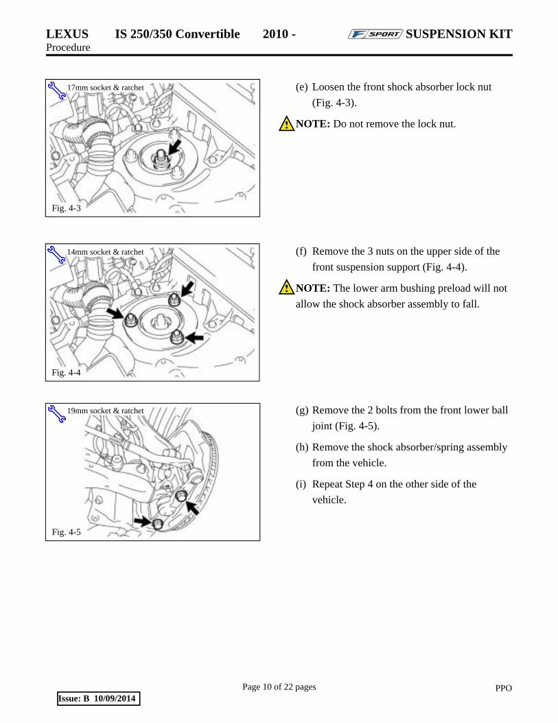
(e) Loosen the front shock absorber lock nut
(Fig. 4-3).
NOTE: Do not remove the lock nut.
(f) Remove the 3 nuts on the upper side of the
front suspension support (Fig. 4-4).
NOTE: The lower arm bushing preload will not
allow the shock absorber assembly to fall.
(g) Remove the 2 bolts from the front lower ball
joint (Fig. 4-5).
(h) Remove the shock absorber/spring assembly
from the vehicle.
(i) Repeat Step 4 on the other side of the
vehicle.
17mm socket & ratchet
Fig. 4-3
14mm socket & ratchet
Fig. 4-4
19mm socket & ratchet
Fig. 4-5

LEXUS IS 250/350 Convertible 2010 - SUSPENSION KIT Procedure
Page 11 of 22 pages PPOIssue: B 10/09/2014
5. Replace the Front Springs and Shock Absorbers.
(a) Compress the spring enough to remove
tension from the upper spring support (Fig.
5-1).
(b) Remove the lock nut (Fig. 5-2). It will not be
reused.
(c) Remove the front suspension support
assembly with the front upper coil spring
insulator (Fig. 5-2). Retain them for
reinstallation.
(d) Remove the coil spring.
(e) Place a provided spring seat over the new
shock absorber assembly.
NOTE: A groove machined into the spring seat
rests on the snap ring fitted to the body of the
shock absorber.
(f) Transfer the lower spring insulator from the
factory shock absorber to the new spring seat
(Fig. 5-3).
(g) Confirm that the lower spring insulator is
indexed properly and free of debris (Fig. 5-
3).
(h) Compress a new front spring and place it
over the shock absorber assembly.
Spring compressor
Fig. 5-1
17mm socket & ratchet
Fig. 5-2
Fig. 5-3

LEXUS IS 250/350 Convertible 2010 - SUSPENSION KIT Procedure
Page 12 of 22 pages PPOIssue: B 10/09/2014
(i) Confirm that the end of the spring sits in the
stepped portion (*a) of the lower spring seat
(Fig. 5-4).
NOTE: Ensure the F-Sport logo is facing
outward.
(j) Place a supplied collet/spacer over the piston
shaft (Fig. 5-5).
(k) Install the front spring bumper onto the front
suspension support assembly (Fig. 5-6).
(l) Align the bolt heads of the front suspension
support assembly with the cutouts of the
front upper coil spring insulator (Fig. 5-6).
(m) Install the front upper coil spring insulator on
the front suspension support assembly (Fig.
5-6).
Fig. 5-4
Fig. 5-5
Fig. 5-6

LEXUS IS 250/350 Convertible 2010 - SUSPENSION KIT Procedure
Page 13 of 22 pages PPOIssue: B 10/09/2014
(n) Match the shape of the piston shaft end to the
hole in the front suspension support assembly
to install the front shock absorber (Fig. 5-7).
(o) Turn the front suspension support assembly
so that the bolts align to the lower shock
absorber eyelets (Fig. 5-8).
(p) Temporarily tighten a supplied lock nut to
the front shock absorber.
6. Install the Front Shock Absorber/Spring Assemblies.
(a) Install the front shock absorber assembly into
the vehicle and tighten the 3 nuts on the
suspension support (engine bay) side (Fig. 6-
1).
Torque: 67 N·m (683 kgf·cm, 49 ft·lbf)
Fig. 5-7
Flats
17mm socket & ratchet
Fig. 5-8
14mm socket & torque wrench
Fig. 6-1

LEXUS IS 250/350 Convertible 2010 - SUSPENSION KIT Procedure
Page 14 of 22 pages PPOIssue: B 10/09/2014
(b) Install the front shock absorber lower side on
the front lower suspension arm and insert the
bolt from the rear of the vehicle (Fig. 6-2).
(c) Temporarily tighten the nut while holding the
bolt.
NOTE: The nut will be fully tightened after
settling the suspension.
(d) Replace the 2 bolts into the front lower ball
joint (Fig. 6-3).
Torque: 120 N·m (1,220 kgf·cm, 89 ft·lbf)
(e) Install the front speed sensor to the front
shock absorber and reconnect it (Fig. 6-4).
Torque: 6.0 N·m (61 kgf·cm, 53 in·lbf)
(f) Repeat Step 6 on the other side of the
vehicle.
(g) Install the F-Sport front sway bar following
the F-Sport Sway Bar Set PPO instructions.
(h) Install the front wheel/tire assemblies onto
the vehicle. Hand start the lug nuts.
19mm socket & wrench and ratchet
Fig. 6-2
17mm socket & torque wrench
Fig. 6-3
10mm socket & torque wrench
Fig. 6-4
LEXUS IS 250/350 Convertible 2010 - SUSPENSION KIT Procedure
Page 15 of 22 pages PPOIssue: B 10/09/2014
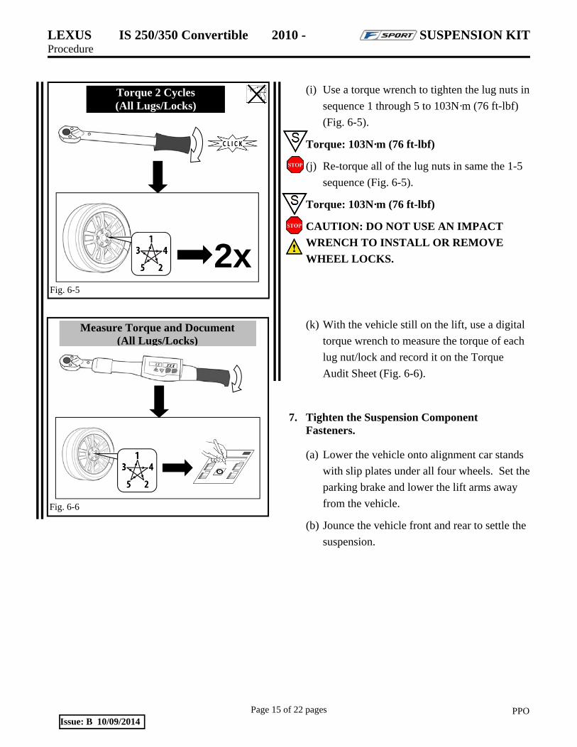
(i) Use a torque wrench to tighten the lug nuts in
sequence 1 through 5 to 103N·m (76 ft-lbf)
(Fig. 6-5).
Torque: 103N·m (76 ft-lbf)
(j) Re-torque all of the lug nuts in same the 1-5
sequence (Fig. 6-5).
Torque: 103N·m (76 ft-lbf)
CAUTION: DO NOT USE AN IMPACT
WRENCH TO INSTALL OR REMOVE
WHEEL LOCKS.
(k) With the vehicle still on the lift, use a digital
torque wrench to measure the torque of each
lug nut/lock and record it on the Torque
Audit Sheet (Fig. 6-6).
7. Tighten the Suspension Component Fasteners.
(a) Lower the vehicle onto alignment car stands
with slip plates under all four wheels. Set the
parking brake and lower the lift arms away
from the vehicle.
(b) Jounce the vehicle front and rear to settle the
suspension.
Fig. 6-6
Measure Torque and Document (All Lugs/Locks)
2xFig. 6-5
Torque 2 Cycles (All Lugs/Locks)

LEXUS IS 250/350 Convertible 2010 - SUSPENSION KIT Procedure
Page 16 of 22 pages PPOIssue: B 10/09/2014
(c) Torque the front lower shock absorber bolt
(Fig. 7-1).
Torque: 157 N·m (1,600 kgf·cm, 116 ft·lbf)
(d) Torque the new front shock absorber
assembly lock nut (Fig. 7-2).
Torque: 28 N·m (286 kgf·cm, 21 ft·lbf)
(e) Install the engine room side covers.
(f) Torque the nuts and bolts on the rear No. 2
suspension arm assembly (Fig. 7-3).
Torque(A): 161 N·m (1,640 kgf·cm, 118 ft·lbf)
Torque(B): 110 N·m (1,120 kgf·cm, 80 ft·lbf)
Torque(C): 27 N·m (275 kgf·cm, 20 ft·lbf)
Torque(D): 150 N·m (1,530 kgf·cm, 111 ft·lbf)
NOTE: Nut D on the RH side cannot be accessed with a 19mm socket. Snap-on Torque Head, P/N QXXM19A or QXOM19A (Fig. 7-4) is recommended to be used and torqued to the spec above.
19mm socket & wrench and torque wrench
Fig. 7-1
17mm socket & torque wrench
Fig. 7-2
Fig. 7-4
19mm socket & wrench and torque wrench
Fig. 7-3

LEXUS IS 250/350 Convertible 2010 - SUSPENSION KIT Procedure
Page 17 of 22 pages PPOIssue: B 10/09/2014
8. Adjust the Wheel Alignment.
(a) Confirm the alignment system has been
calibrated.
(b) Install the wheel clamps (Fig. 8-1).
(1) Place the lower feet onto the outside lip
of the alloy wheel.
(2) Expand the clamp until the upper
mounting feet grip the outside lip of the
alloy wheel rim.
(3) The clamp should be attached firmly.
(c) Perform the run-out procedure.
(1) Place the TL-30 on the disc extending
from the wheel clamp (Fig. 8-2).
(2) Level the TL-30, using the SAI scale on
the top of the post. Make sure the TL-30
can move easily, so that it stays relatively
level when the wheel clamp is rotated.
(3) Rotate the wheel clamp until the
installation knob is at a 6 o’clock
position. Set the caster bubble to zero on
the caster scale; this is done with the
caster adjustment knob, which is located
on body of the TL-30 (Fig. 8-3).
Fig. 8-1
Fig. 8-3
Fig. 8-2

LEXUS IS 250/350 Convertible 2010 - SUSPENSION KIT Procedure
Page 18 of 22 pages PPOIssue: B 10/09/2014
(4) Rotate the wheel clamp ½ turn; the
installation knob should be at the 12
o’clock position (Fig. 8-4).
(5) Level the TL-30 and read the number on
the caster scale.
(6) Adjust the bubble to the point halfway
between 0 and the current reading using
the RED knob on the wheel clamp.
(When making this adjustment, it is
important not to move the bubble with
the caster adjustment knob.)
(7) Rotate the wheel ¼ turn to the left so the
installation knob is at the 9 o’clock
position (Fig. 8-5).
(8) Level the TL-30 and set the caster bubble
to zero with the caster adjustment knob.
(9) Rotate the wheel ½ turn, until the
installation knob is at the 3 o’clock
position.
(10) Level the TL-30 and read the number
on the caster scale.
(11) Adjust the caster bubble to the point
halfway between 0 and the current
reading using the two BLACK knobs on
the wheel clamp.
Fig. 8-4
Fig. 8-5
LEXUS IS 250/350 Convertible 2010 - SUSPENSION KIT Procedure
Page 19 of 22 pages PPOIssue: B 10/09/2014
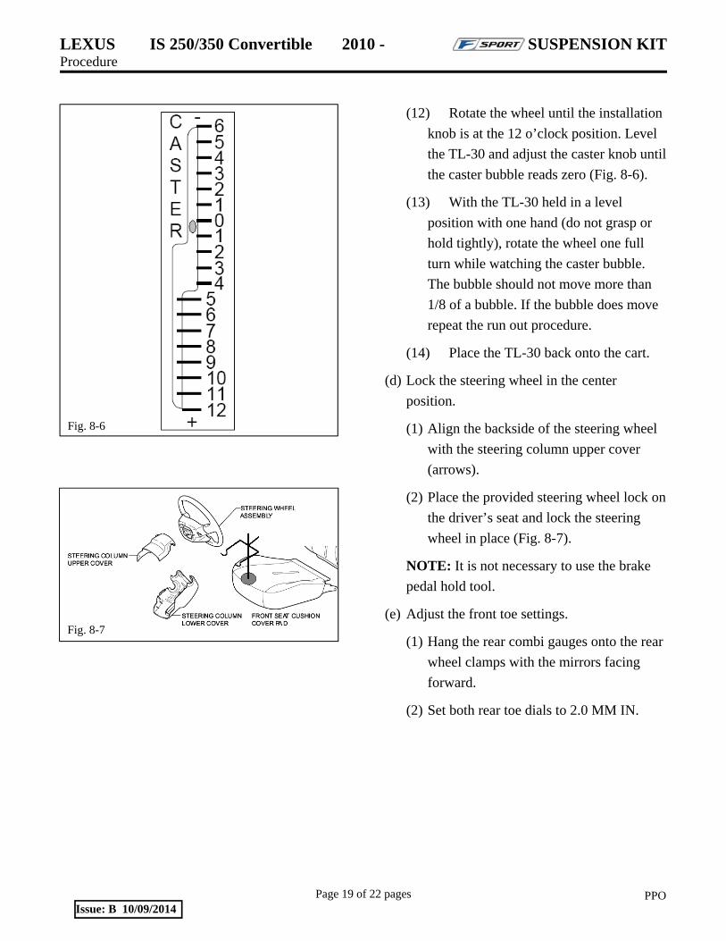
(12) Rotate the wheel until the installation
knob is at the 12 o’clock position. Level
the TL-30 and adjust the caster knob until
the caster bubble reads zero (Fig. 8-6).
(13) With the TL-30 held in a level
position with one hand (do not grasp or
hold tightly), rotate the wheel one full
turn while watching the caster bubble.
The bubble should not move more than
1/8 of a bubble. If the bubble does move
repeat the run out procedure.
(14) Place the TL-30 back onto the cart.
(d) Lock the steering wheel in the center
position.
(1) Align the backside of the steering wheel
with the steering column upper cover
(arrows).
(2) Place the provided steering wheel lock on
the driver’s seat and lock the steering
wheel in place (Fig. 8-7).
NOTE: It is not necessary to use the brake
pedal hold tool.
(e) Adjust the front toe settings.
(1) Hang the rear combi gauges onto the rear
wheel clamps with the mirrors facing
forward.
(2) Set both rear toe dials to 2.0 MM IN.
Fig. 8-6
Fig. 8-7

LEXUS IS 250/350 Convertible 2010 - SUSPENSION KIT Procedure
Page 20 of 22 pages PPOIssue: B 10/09/2014
(3) Hang the front laser guns onto the front
wheel clamps.
(a) Turn the guns on and confirm the
laser is hitting the rear scales and
bouncing back to the front scales
(Fig. 8-8).
(b) Check to make sure that the front
cross-toe laser is hitting the cross-toe
mirror and then bouncing back to the
cross-toe box. If not, adjust the pivot
knob up or down on the side of the
box until the laser reaches the mirror.
(4) Set both front toe dials to 0.5 MM IN.
(5) Loosen the front tie rod end locking nuts
(Fig. 8-9).
(6) Adjust the front tie rods evenly until the
cross-toe laser is reflected off the toe
mirror in the right laser box and back into
the hole of the left laser box (Fig. 8-9).
(7) Make sure that the lasers hitting the
numbers on the rear combi gauges match
each other. If not, adjust the tie rods until
the numbers match and the front laser
falls in the laser box hole.
Fig. 8-8
Fig. 8-9
17mm & 19mm wrench
LEXUS IS 250/350 Convertible 2010 - SUSPENSION KIT Procedure
Page 21 of 22 pages PPOIssue: B 10/09/2014
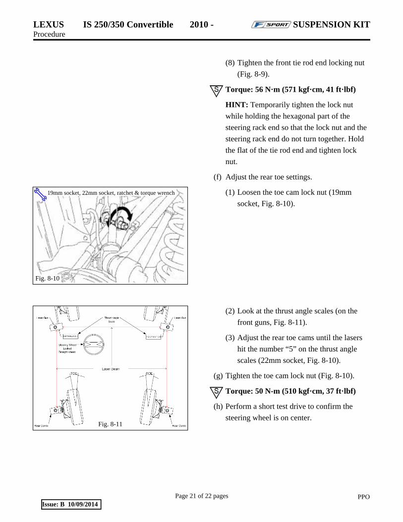
(8) Tighten the front tie rod end locking nut
(Fig. 8-9).
Torque: 56 N·m (571 kgf·cm, 41 ft·lbf)
HINT: Temporarily tighten the lock nut
while holding the hexagonal part of the
steering rack end so that the lock nut and the
steering rack end do not turn together. Hold
the flat of the tie rod end and tighten lock
nut.
(f) Adjust the rear toe settings.
(1) Loosen the toe cam lock nut (19mm
socket, Fig. 8-10).
(2) Look at the thrust angle scales (on the
front guns, Fig. 8-11).
(3) Adjust the rear toe cams until the lasers
hit the number “5” on the thrust angle
scales (22mm socket, Fig. 8-10).
(g) Tighten the toe cam lock nut (Fig. 8-10).
Torque: 50 N-m (510 kgf·cm, 37 ft·lbf)
(h) Perform a short test drive to confirm the
steering wheel is on center.
Fig. 8-10
19mm socket, 22mm socket, ratchet & torque wrench
Fig. 8-11
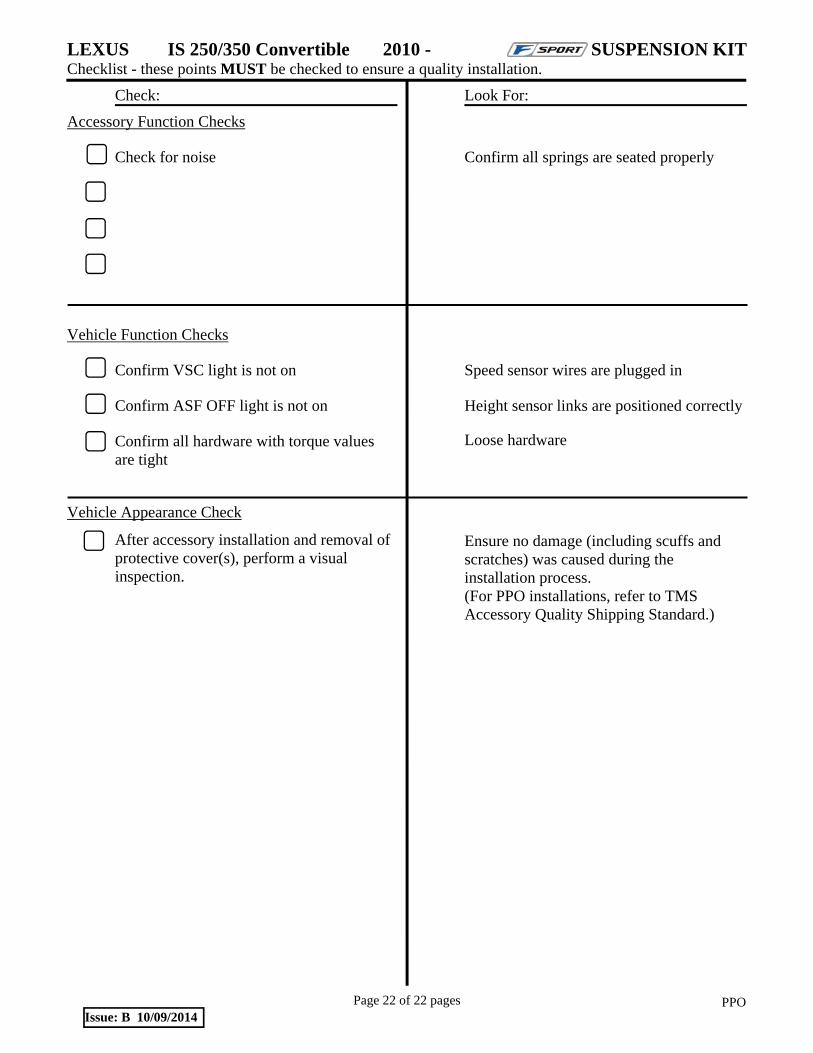
LEXUS IS 250/350 Convertible 2010 - SUSPENSION KIT Checklist - these points MUST be checked to ensure a quality installation.
Check: Look For:
Page 22 of 22 pages PPOIssue: B 10/09/2014
Accessory Function Checks
Check for noise
Vehicle Function Checks
Confirm VSC light is not on
Confirm ASF OFF light is not on
Confirm all hardware with torque values are tight
Confirm all springs are seated properly
Speed sensor wires are plugged in
Height sensor links are positioned correctly
Loose hardware
Vehicle Appearance Check
After accessory installation and removal of protective cover(s), perform a visual inspection.
Ensure no damage (including scuffs and scratches) was caused during the installation process. (For PPO installations, refer to TMS Accessory Quality Shipping Standard.)