Embed Size (px)
Citation preview

User Manual for LEVIFLOW® LFS-SU Flowmeters www.levitronix.com
PL-4509-00, Rev03, DCO# 16-181 First Release: 11-Dec-14 Last Update: 28-Dec-16
LEVIFLOW® LFS-SU SINGLE-USE FLOWMETERS
USER MANUAL
LEVIFLOW® Single-Use Sensors: LFS-03SU, -06SU, -10SU, -20SU
LEVIFLOW® Converter: LFC-1C-PC
This manual contains information necessary for the safe and proper use of the LEVIFLOW® LFS-SU single-use flowmeter series. Included are specifications for the standard configuration, components, and instructions regarding its use, installation, operation, adjustment, inspection and maintenance. For special configuration of the LEVIFLOW® flowmeters refer to accompanying information. If the flowmeters have to be configured for other parameter settings
then the LEVIFLOW® Configuration Software (see relevant manual Levitronix Doc.# PL-4501-00) is necessary.
Please familiarize yourself with the contents of this manual to ensure the safe and effective use of this product. After reading, please store the manual where the personnel responsible for operating can readily refer to it at any time.

User Manual for LEVIFLOW® LFS-SU Flowmeters www.levitronix.com
PL-4509-00, Rev03, DCO# 16-181 2
Table of Contents
1 SAFETY PRECAUTIONS .......................................................................................................................................... 3
2 SPECIFICATIONS ..................................................................................................................................................... 4 2.1 Component Overview ........................................................................................................................................ 4 2.2 Standard System Configurations ....................................................................................................................... 5 2.3 Specifications of Converter ................................................................................................................................ 5
2.3.1 General Specifications ..................................................................................................................................................... 5 2.3.2 Overview of Parameter Configuration ............................................................................................................................... 6
2.4 Specifications of Single-Use Sensors ................................................................................................................ 7 2.4.1 General Specifications ..................................................................................................................................................... 7
2.5 Basic Dimensions of Main Components ............................................................................................................ 8 2.5.1 Dimensions of Sensors .................................................................................................................................................... 8 2.5.2 Dimensions of Converter .................................................................................................................................................. 9 2.5.3 Dimensions of Adaptor Cables ......................................................................................................................................... 9
3 INSTALLATION ....................................................................................................................................................... 11 3.1 Installation of Converter ................................................................................................................................... 11
3.1.1 Overview and Preparation .............................................................................................................................................. 11 3.1.2 Instructions for Electrical Installation ............................................................................................................................... 12 3.1.3 Instructions for Mechanical Installation ........................................................................................................................... 13
3.2 Installation of Sensors ..................................................................................................................................... 14 3.2.1 Overview and Preparation .............................................................................................................................................. 14 3.2.2 Instructions for Electrical Installation ............................................................................................................................... 14 3.2.3 Instructions for Mechanical and Hydraulic Installation ..................................................................................................... 15
4 OPERATION ............................................................................................................................................................ 16 4.1 General Timing Specifications ......................................................................................................................... 16
4.1.1 Startup Time .................................................................................................................................................................. 16 4.1.2 Thermal Stability Time .................................................................................................................................................... 16 4.1.3 Zero Adjustment Activation Time .................................................................................................................................... 16 4.1.4 Automatic Zero Adjustment duration ............................................................................................................................... 16
4.2 Standalone Operation ...................................................................................................................................... 16 4.2.1 Standalone Operation with Display ................................................................................................................................. 16 4.2.2 Display Messages .......................................................................................................................................................... 16
4.3 Operation with PLC Interface ........................................................................................................................... 17 4.3.1 Typical Setups Using the PLC Interface ......................................................................................................................... 17
4.4 Operation with LEVIFLOW® Configuration Software ....................................................................................... 18 4.5 Operation with RS485 ...................................................................................................................................... 18
5 INSPECTION AND MAINTENANCE ....................................................................................................................... 19
6 TROUBLESHOOTING ............................................................................................................................................. 19 6.1 Common Troubles ........................................................................................................................................... 19 6.2 Troubleshooting with LEVIFLOW® Configuration Software.............................................................................. 19
7 TECHNICAL SUPPORT .......................................................................................................................................... 20
8 APPENDIX ............................................................................................................................................................... 21 8.1 Regulatory Status ............................................................................................................................................ 21
8.1.1 CE Marking .................................................................................................................................................................... 21 8.2 Symbols and Signal Words .............................................................................................................................. 22

User Manual for LEVIFLOW® LFS-SU Flowmeters www.levitronix.com
PL-4509-00, Rev03, DCO# 16-181 3
1 Safety Precautions
CAUTION
Do not under any circumstances open the converter or sensor housing. Levitronix does not assume responsibility for any damage, which occurs under such circumstances.
! WARNING
Hazardous voltage may be present.
In case of the usage of an inadequate AC/DC power supply, mains voltages may be present (even if the system is designed for 24VDC).
The converter must be placed in a spill protected environment. Do not under any circumstances open the powered converter.
The usage of galvanic separated 3rd party tested (like CE and/or UL) AC/DC supply is highly recommended.
! WARNING
Toxic chemicals may be present.
When using the flowmeter to measure chemicals skin contact and toxic gases may be hazardous to your health. Wear safety gloves and other appropriate safety equipment.

User Manual for LEVIFLOW® LFS-SU Flowmeters www.levitronix.com
PL-4509-00, Rev03, DCO# 16-181 4
2 Specifications
2.1 Component Overview
Figure 1: LEVIFLOW® flowmeter components
Pos. Part Name Article # 1% Accuracy Flow Range
Fitting Connector Note
1a LFS-03SU-Z LFS-03SU-Z-G25
100-30375 100-30399
35 – 800 ml/min
Triclamp 3/8” (ASME BPE 2009)
Circular Hirose type with IP67.
--
1b
LFS-06SU-Z LFS-06SU-Z-G25
LFS-06SU-Z-SC1 LFS-06SU-Z-SC1-G25
100-30377 100-30400
100-30394 100-30406
1.7 – 8 l/min
0.08 – 8 l/min
1c LFS-10SU-Z LFS-10SU-Z-G25
100-30397 100-30405
4 – 20 l/min Triclamp 1/2” (ASME BPE 2009)
1d LFS-20SU-Z LFS-20SU-Z-G25
100-30379 100-30404
17 – 80 l/min Triclamp 1” (ASME BPE 2009)
Table 1: Standard single-use flow sensor configurations
Pos. Part Name Part # Description Interfaces
2 (a+b)
LFC-1C-PC 100-30374 Single Channel Converter
Analog Output (4 – 20 mA), 2x Digital Output, 1x Digital Input, RS485 (MODBUS) protocol.
Note: EMI ferrite (2b) for flow sensor cable included in converter package.
Table 2: LEVIFLOW® converter
Pos. Part Name Part # Features Special Feature / Description
3a
LFI-C.1-10
LFI-C.1-30
LFI-C.1-60
190-10307
190-10308
190-10309
Cable length: 1 m, PVC
Cable length: 3 m, PVC
Cable length: 6 m, PVC Interconnect cable for connection between sensor and converter.
3b
LFE-C.2-10
LFE-C.2-30
LFE-C.2-60
190-10310
190-10311
190-10312
Cable length: 1 m, PVC
Cable length: 3 m, PVC
Cable length: 6 m, PVC
Extension cable with wall-mountable connector for cabinet mounting.
Delivered with protective cap on connector at wall-mountable side.
4 YN-485I-TR, USB to RS485 Adaptor-TR Isolated
100-30392
Structure/Design
Purpose
USB connector (4a) with termination resistor and cable with connector pair (4b and 4c) for external RS485 wire connection. Magnetically isolated. Cable length is 2m.
For communication over RS485 of converter with PC (service, debug.)
Table 3: Accessories
1a 2a
3a
4a
1b
3b
1d
4c
4b
2b
1c

User Manual for LEVIFLOW® LFS-SU Flowmeters www.levitronix.com
PL-4509-00, Rev03, DCO# 16-181 5
2.2 Standard System Configurations
Figure 2: Standard flowmeter system configuration
2.3 Specifications of Converter
2.3.1 General Specifications
Characteristics Description or Values
Power Supply Voltage / Current / Inrush Current 24 VDC ± 10% / 150 mA / Peak of 3.8 A within 210 µs
Ambient Temp / Humidity Range 0 – 50 °C (32 – 122 °F) / 30 - 85% R.H. (no condensation)
Enclosure Classification and Material IP-20 (indoor use), ABS
Interfaces
(see Figure 6 for detailed PIN designation and electrical specification)
- RS485 -> MODBUS protocol -> max. array of 99 channels
- 1x Analog Output: 4 – 20mA (0 – 20mA configurable)
- 2x Digital Outputs: Flow Alarm, Measurement Error, Volume Counter Pulse, Volume Counter Alarm, Flow as Frequency or Bubble Detection, Custom Output (default: normally open)
- 1x Digital Input: Volume Counter Reset or Zero Adjust
- 4 Digit display (flow rate, volume counter, error codes), re-zero button
- Address potentiometers for RS485 address setting
Configuration Parameters
(Available and configurable with RS485/USB converter and configuration software)
- Viscosity
- Low Cutoff
- Dampening time (filter)
- Full scale setting
- Linearization (15 points)
- Alarm Outputs (High and Low Alarm)
- Volume Counter and Volume Counter Alarm Settings
Weight / Dimensions / Mounting 130 g / 123 x 75 x 17.5 mm / DIN rail
Duration for Activation of Manual and Digital Zeroing 3 sec
Duration of Zeroing Procedure LFC-1C-PC: normal 26 sec , maximum 60 sec
Duration of Measurement Ready after Power-On Warm-Up Time for Full Performance Measurements
10 sec. 30 min.
Table 4: Specifications for converters LFC-1C-PC
Single-Channel Converter LFC-1C-PC
4-D
igit D
isp
lay
Ze
ro A
dju
stm
en
t
Ad
ress S
ettin
g fo
r R
S4
85
Piezo Transducers
In-/Output Electrical Interface
Power Supply: 24 VDC
Analog and
Digital Outputs
- 1x Analog Output
- 2x Digital Outputs
- 1x Digital Input
Digital
Signal Processor
DSP
Adaptor/Extension Cable
Wallmountable connector
for cabinet mounting
Interconnect Cable
Various lengths.
Direct connection possible.
RS485 (MODBUS)
- Configuration with PC Software
- Data Logging
- Fieldbus Array of Multiple Sensors
LE
VIF
LO
W®
Sin
gle
-Us
e S
en
so
r L
FS
-xx
SU
Flow Out
Flow In
Co
nn
ec
tor
Bo
x
EMI Ferrite
2a
1
3b
3a
4
2b

User Manual for LEVIFLOW® LFS-SU Flowmeters www.levitronix.com
PL-4509-00, Rev03, DCO# 16-181 6
2.3.2 Overview of Parameter Configuration
Table 5 shows the standard (“Default”) and possible parameter configurations of the flowmeters. This user manual is dealing with the standard configuration. For setting up other configurations the LEVIFLOW®
Configuration Software is needed. Consult the “Configuration-SW User Manual” (Levitronix Doc.# PL-4501-00) for more detailed description.
Block Parameter Option/Range Default Note
Basic
Sensor size LFS-xxSU
xx = 03, 06, 20 xx = 03, 06 or 20
(accord. Sensor size) --
Full scale 0.01 – 100 L/min (accord. Sensor size) Default Values: LFS-03SU = 0.8 L/min, LFS-06SU = 8 L/min LFS-10SU = 20 L/min, LFS-20SU = 80 L/min
Damping time 0 – 25 s 2 s Low-pass filter with T
f dB
2
13
Low cutoff 0.0 – 25.0 % 2 % Flow cut to 0 below this percentage of full-scale
If cutoff 0% is chosen, negative flow becomes visible
Kinematic Viscosity 0.00 – 99.99 cSt 1 cSt Kinematic Visc. = Dynamic Visc. / Density
Display Settings
Displayed Parameter Flow Value in L/min
Flow Value in mL/min Volume Counter Value
Flow Value in L/min
Parameter shown in converter display
Measurement Resolution
0 digits (#.) 1 digits (#.#)
2 digits (#.##) 3 digits (#.###)
3 digits (#.###)
Analog output settings
Analog output setting 4 – 20 mA or
0 – 20 mA 4 – 20 mA --
Digital input settings
Digital input
Volume counter reset
Zero adjust
Set Volume Counter to zero
Zero adjust Automates zeroing, when liquid type changes
Digital output settings
Digital output 1
Flow alarm High Flow alarm Low
Vol. counter alarm H Vol. counter alarm HH
Vol. counter Pulse Measurement Error Flow as Frequency
Bubble detect Custom Output
Flow alarm High
- Upper flow limit detection - Lower flow limit detection - Flow volume detection first value (one-time) - Flow volume detection second value - Pulse per volume - Error signal (empty sensor etc.) - Flow as Frequency output (100% of full-scale = 1 kHz)
- Bubble detected signal - Bits of equipment status can be OR-ed on the output
Digital output 2 Flow alarm Low
Flow alarm
Hysteresis (Flow alarm) 0 – 20 % 0 % Can be used to get tolerance to noise.
Alarm high 0 – 125 % 105 % Alarm setting In percentage of full-scale.
Contact type N.O. = normally open
N.C. = normally closed N.O. = norm. open For digital outputs of converter.
Alarm low -10 – 125 % -5 % Alarm setting In percentage of full-scale.
Contact type N.O. = normally open
N.C. = normally closed N.O. = norm. open For digital outputs of converter.
Volume counter settings
Volume counter enable (activation box)
activated, not activated not activated These are settings for volume detection (integration of flow).
Has to be active for the options “ Vol. Counter Alarm H”, “Vol. Counter Alarm HH” and “Vol. Counter Pulse”.
Volume counter base unit 1 mL, 1 L, 1 m3 1 mL
Multiplier factor 0.01, 0.1, 10, 100, 1000 0.1
Volume counter pulse length 0.5, 50, 100ms 0.5 ms
Volume counter alarm enable (activation box)
activated, not activated not active
-> Settings for one-time volume detection.
-> Volume = “Volume unit” x “Multiplier factor” x “Vol. Counter Alarm H“ value”
-> Has to be active for the options “Vol. Counter Alarm H”, “Vol. Counter Alarm HH”.
Value (Volume counter alarm H)
0 – 999999 --
Contact type (H) N.O. = normally open
N.C. = normally closed N.O. = norm. open
Value (Volume counter alarm HH)
0 – 999999 --
Contact type (HH) N.O. = normally open
N.C. = normally closed N.O. = norm. open
Measurement Error Settings
Instant Measurement Error Ignore Time
0-99 s 10s
During this time instant measurement errors are ignored. If an instant measurement error stays active for longer time than this time, measurement error arises.
Flow Level on Measurement Error
0%, -25, 125% Hold
0 % Signal level of analog output and flow, when measurement error arises
Bubble Detection Settings
Bubble Detect Hold Time 0 – 99 s 0 s For bubble or particle detection in the process
Table 5: Overview of parameters

User Manual for LEVIFLOW® LFS-SU Flowmeters www.levitronix.com
PL-4509-00, Rev03, DCO# 16-181 7
2.4 Specifications of Single-Use Sensors
2.4.1 General Specifications
Characteristics LFS-03SU LFS-06SU LFS-06SU-SC1
LFS-10SU LFS-20SU
Flow Range [l/min] 0 – 0.8 l/min 0 – 8 l/min 0 – 20 l/min 0 – 80 l/min
ID of Measurement Path 2.5 mm 6 mm 10 mm 20 mm
Accuracy of Reading
Note: Repeatability < Accuracy/2 See Figure 3
LFS-06: >1.7 l/min: ±1 % <1.7 l/min: ±17 ml/min
LFS-06-SC1: >0.08 l/min: ±1 % <0.08 l/min: ±0.8 ml/min
>4.7 l/min: ±1 % <4.7 l/min: ±47 ml/min
>18.8 l/min: ±1 % <18.8 l/min: ±188 ml/min
Weight
Wetted Surface Area Wetted Volume
42 g
29.5 cm2 4 ml
43 g
32.2 cm2 4.8 ml
61 g
53.2 cm2 61 ml
125 g
173.5 cm2 95.8 ml
Maximum Fluid Pressure 5 bar 5 bar 5 bar 5 bar
Pressure Drop Coefficient C
P = C x Q2 , (for water)
Q = Flow [l/min], P = Press. Drop [kPa = 10mbar]
16.8 at 20°C 0.88 at 20°C 0.075 at 20°C 0.0035 at 20°C
Fluid Temperature / Ambient Temp. 10–60 oC (50–140 oF) / 0– 40 oC (32-104 oF)
Kinematic Viscosity / Sound Speed 0.8 – 40 mm2/s (0.8 – 40 cSt) / 1000 – 2200 m/s
IP Classification IP-65 (for connected sensor)
Wet Material / Sterilization Methods Polypropylene (FDA, USP VI, ADI free) / Gamma robust for up to 40 kGy
Electrical Connector Circular type (IP-67), lock-release mounting
Cables Various extension cables available.
Table 6: Specifications of single-use flow sensors (all data based on calibration with water at 20°C)
Figure 3: Accuracy and repeatability of reading for LFS-03SU single-use sensor
0%
1%
2%
3%
4%
5%
6%
7%
8%
9%
10%
1 10 100 1000[mlpm]
Accuracy of Reading
Repeatability of Reading
Full Scale Change Line
Full Scale = 35 mlpm Full Scale = 800 mlpm

User Manual for LEVIFLOW® LFS-SU Flowmeters www.levitronix.com
PL-4509-00, Rev03, DCO# 16-181 8
2.5 Basic Dimensions of Main Components
2.5.1 Dimensions of Sensors
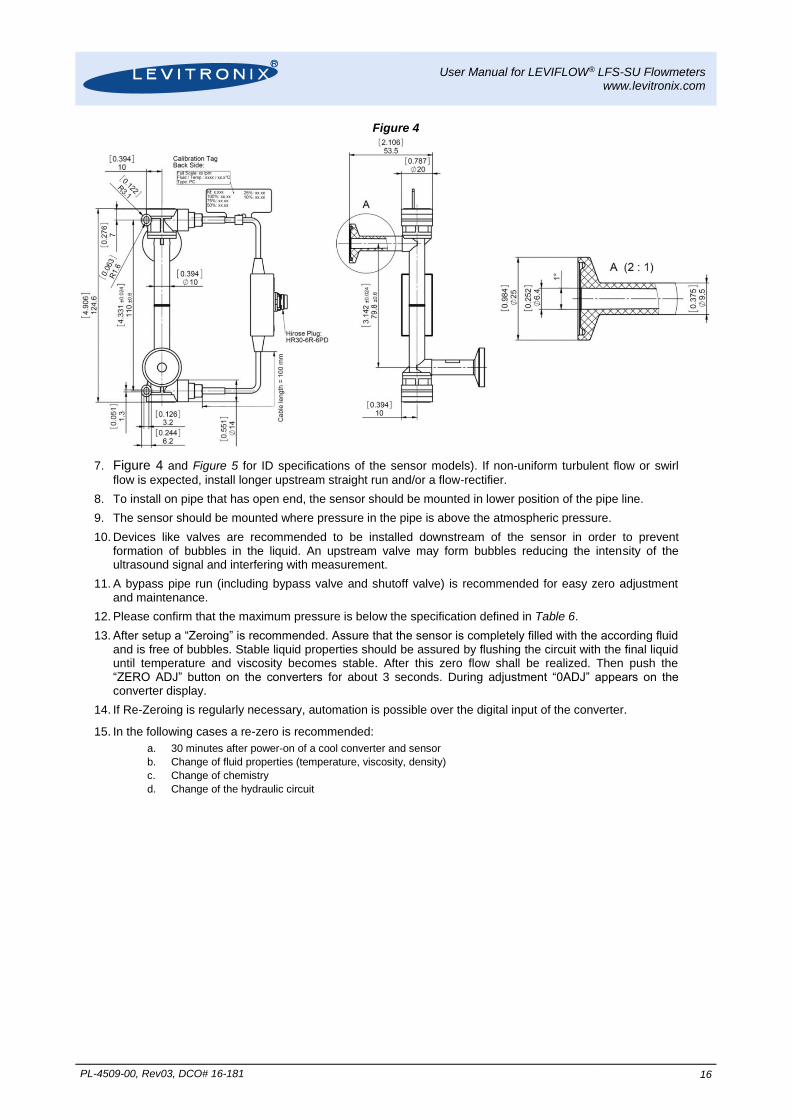
Figure 4: Dimensions of LFS-03SU and LFS-06SU flow sensors
Sensor Type
Triclamp Fitting Size (ASME BPE 2009)
Dimensions in [mm]
a b c D d e f g L
LFS-10SU-Z 1/2" 80 138 Ø 12.7 (= 1/2”) Ø 25 Ø 9.4 44.4 18.6 24 110
LFS-20SU-Z 1” 161.2 231.2 Ø 25.4 (= 1”) Ø 50.5 Ø 22.2 82.5 28 34 160
Figure 5: Dimensions of LFS-10SU and LFS-20SU flow sensors
Triclamp 3/8“ ASME BPE 2009

User Manual for LEVIFLOW® LFS-SU Flowmeters www.levitronix.com
PL-4509-00, Rev03, DCO# 16-181 9
2.5.2 Dimensions of Converter
Figure 6: Dimensions and layout of interfaces of converter LFC-1C-PC
2.5.3 Dimensions of Adaptor Cables
Figure 7: Dimensions of wall mountable extension cable LFE-C.2 (Can be used for electrical cabinet mounting. Minimum bending radius > 10 x cable radius)
Mounting Panel Dimensions
Length = 1,3,6 m
LFC-1C-PC
100-30374
Delivered with protective dust cap on connector)

User Manual for LEVIFLOW® LFS-SU Flowmeters www.levitronix.com
PL-4509-00, Rev03, DCO# 16-181 10
Figure 8: Dimensions of interconnect cable LFI-C.1 (Minimum bending radius > 10 x cable radius)
Connector Hirose Plug Male
HR30-6P-6P
Connector Hirose Plug Female HR30-6P-6S
Length = 3m

User Manual for LEVIFLOW® LFS-SU Flowmeters www.levitronix.com
PL-4509-00, Rev03, DCO# 16-181 11
3 Installation
3.1 Installation of Converter
3.1.1 Overview and Preparation
Figure 9: Single channel converter LFC-1C-PC
Pin # Designation Specification Standard Configuration Description
1 DC24V+ Voltage: 24 VDC ±10% Current: 150 mA Start Current: 4.4 A 2ms
-- Supply voltage 2 DC24V-
3 FG Field Ground See note in installation Section 3.1.2 Field ground
4 Analog Out + 4-20 mA or 0-20mA configurable
Load resistance < 600
Flow reading with 4-20 mA. Standard full scale flow range of each sensor model.
Flow rate signal. Update rate is 10ms. 5 Analog Out -
6 Digital Out1 + Max. rating 30 V DC, 20 mA Open collector
Configurable as Alarm High, Alarm Low, Measurement Error, Volume Counter Pulse, Volume Counter Alarm, Flow as Frequency, Bubble Detect
- Parameter: Flow Alarm High - Setting: 105% of full scale - Normally opened
Contact is made, when 105% of full scale flow rate is exceeded.
7 Digital Out2 + - Parameter: Flow Alarm Low - Setting: -5% of full scale - Normally opened
Contact is made, when -5% of full scale flow rate is reached.
8 COM - Common Digital Out ground.
9 Digital In + No-voltage contact or transistor open collector
Zero Adjustment
Is needed, if zero adjustment wants to be triggered by PLC or when volume counter function is used (integration of flow with volume detection)
10 Digital In -
11 RS485 + RS485 MODBUS Protocol
Digital communication in a sensor array. or configuration with configuration SW. 12 RS485 -
Table 7: Standard configuration of interface connector (PLC and fieldbus)
a
DIN Rail Mounting Sensor Connector
Interface Connector (12 Pin) b
Re-Zero Button
High ADRS LOW ADRS 4 Digit Display
c
LFC-1C-PC

User Manual for LEVIFLOW® LFS-SU Flowmeters www.levitronix.com
PL-4509-00, Rev03, DCO# 16-181 12
1. If communication over the RS485 bus is used, check the address settings of the potentiometers on the front panel of the converter (see Figure 9c).
The total address is: “High ADRS” x 10 + “Low ADRS” x 1
2. The LEVIFLOW® Configuration Software can be used to debug and configure the flowmeter over
the RS485. For communication with RS485 the MODBUS protocol can be requested at Levitronix.
3.1.2 Instructions for Electrical Installation
1. Remove the DC power from the converter.
2. Remove the interface connector (see Figure 9a) from the converter.
3. Attach the necessary wires (AWG 14-26) according to the pin specifications in Table 7. Strip the sheath approximately 3 mm from the wires end. Insert core into terminal to the end and tighten the screw. Confirm that the wires are securely fixed by pulling it gently by hand.
4. Note: The Field Ground (FG) represents an additional ground potential, which is connected internally to the signal ports of the converter via varistors. Depending on the specific setup, it might be advantageous from an EMC perspective to connect the FG to the PE. However, in case the FG is connected to PE the entire grounding concept of the field installation has to be considered in order to avoid stray and compensating currents triggered by electrical potential differences. If compensating currents between PE and Ground may occur, the FG should not be connected.
5. For usage of a fuse at the power input (24 VDC) a 200 mA slow-blow type is recommended. The peak current after power on of the converter (as specified in Table 4) has to be considered, when choosing the fuse type and the AC/DC power supply.
6. Mount the interface connector to the converter and tighten the 2 connector screws.
7. To attach the sensor to the converter extension cables according to Table 3 can be used. To increase robustness against disturbance from other devices or to reduce cross-talking between multiple flowmeters, the converter comes delivered with an EMI ferrite, which shall be attached to the sensor cable near to the converter (see Figure 10):
Figure 10: Assembly of EMI ferrite
8. Before powering on check again all wiring connections. Confirm that the terminals are securely fastened and that there is no possibility of short circuit.

User Manual for LEVIFLOW® LFS-SU Flowmeters www.levitronix.com
PL-4509-00, Rev03, DCO# 16-181 13
3.1.3 Instructions for Mechanical Installation
! WARNING
Hazardous voltage may be present.
In order to avoiding fluid spills shorting voltages within the converter, place the controller in a spill protected environment (for example protected electronic cabinets).
If explosive flammable gases are present, place the converter in an explosion-proof cabinet.
1. The converter shall be installed in a spill protected cabinet.
2. Assure that sufficient ventilation is provided in order to avoid exceeding the allowed ambient temperature and humidity range: Temperature range: 0–40°C (32–104°F). Humidity range: 30-85% R.H. (no condensation).
3. A wall-mountable extension cable (see Table 3 and Figure 7) is provided in order to panel mount the sensor cable on the cabinet wall. Make a whole to the cabinet wall according to Figure 7. The gasket ring delivered with the extension cable can be used on the inside of the cabinet wall hence achieving an IP-67 sealing.
4. For connecting the sensor to the wall-mountable connector on the cabinet the interconnect cable according to Table 3 and Figure 6 can be used.
Step 1: Align first the Snap-Pin side of the converter with the DIN rail corner (picture a). If the rigid side is aligned first (see picture b) than some of the DIN rail parts of the converter housing might be damaged.
Step 2: Press in the converter on the spring-pin side (see picture c).
Step 3: Press in the fix side of the DIN rail recess of the converter housing (see picture d)
Step 4: Relax the converter and let the snap-pin fix it (see picture e).
Figure 11: Din Rail mounting steps for converter LFC-1C-PC (For dis-mounting follow the steps in reverse order)
a b
c d
e
Snap Pin

User Manual for LEVIFLOW® LFS-SU Flowmeters www.levitronix.com
PL-4509-00, Rev03, DCO# 16-181 14
3.2 Installation of Sensors
3.2.1 Overview and Preparation
Figure 12: Single-use flow sensor models
1. Every sensor comes delivered with a calibration sheet. Check if the S/N on the calibration sheet corresponds to the S/N on the type label of the sensor.
2. Please store the delivered calibration sheet or its data on a defined storage place in order to be able to refer to it in case of problems.
3.2.2 Instructions for Electrical Installation
1. Attach one of the extension cables (see Table 3) coming from the converter to the sensor connector.
2. When applying power the controller needs about 10 seconds for a start-up procedure to be ready. In order to get stable temperature and signals for converter and sensor 30 minutes have to be waited after power-on.
3. After start-up a Zeroing is recommended. Assure that the sensor is completely filled with the according fluid, free of bubbles and that zero flow is realized. Then push the “ZERO ADJ” button on the converters for about 3 seconds. During adjustment “0ADJ” appears on the converter display (about 2 seconds with blinking). The zero adjustment procedure will take about 26-60 seconds.
LFS-06SU 0 – 8 l/min
LFS-20SU 0 – 80 l/min
Fixation Hole
Fixation Hole
LFS-03SU 0 – 0.8 l/min
Connector Box
LFS-10SU 0 – 20 l/min

User Manual for LEVIFLOW® LFS-SU Flowmeters www.levitronix.com
PL-4509-00, Rev03, DCO# 16-181 15
3.2.3 Instructions for Mechanical and Hydraulic Installation
In order to mechanically fix the sensor body fixation holes as shown in Figure 4
1. Figure 4 and Figure 5 can be used.
Assure that the fixation of the flow sensor and that the weight of the inlet and outlet circuit on the fittings are not causing excessive forces resulting in bending the flow measurement path, which might influence the flow measurement.
2. Assure that at the mounting location the allowed ambient temperature and humidity ranges are not exceeded:
Temperature range: 0 – 60 °C (32 – 140 °F) Humidity range: 30 - 85% R.H. (no condensation)
3. The flow circuit should be completely filled with fluid. The converter DSP (Digital Signal Processor) contains special algorithms, which increase the robustness of the measurement against bubbles. However, assure that excessive bubbles are avoided in the circuit.
4. Ideal mounting position for the flow sensor is 450 (see Figure 13) with upward flow direction to avoid the stagnation of bubbles and particles in the measuring tube.
Figure 13: Mounting position of sensor
5. An arrow mark on the flow sensor indicates the flow direction. Make sure that the arrow corresponds to the direction of the flow in the hydraulic circuit.
6. Avoid excessive vibrations such as in the neighborhood of displacement pumps. Insufficient contact of the transducer (within the sensor) onto the pipe wall caused by vibration may result in inaccurate measurement.
The flowmeter measures flow velocity. In order to obtain fully developed flow pattern for accurate velocity measurement, straight run of 10x sensor ID upstream and of 5x ID downstream is recommended (see
Horizontal Mounting Position:
Stagnation of Bubbles and
Particles450 Mounting Position:
Free flow of bubbles and
particles
User Manual for LEVIFLOW® LFS-SU Flowmeters www.levitronix.com
PL-4509-00, Rev03, DCO# 16-181 16
Figure 4
7. Figure 4 and Figure 5 for ID specifications of the sensor models). If non-uniform turbulent flow or swirl
flow is expected, install longer upstream straight run and/or a flow-rectifier.
8. To install on pipe that has open end, the sensor should be mounted in lower position of the pipe line.
9. The sensor should be mounted where pressure in the pipe is above the atmospheric pressure.
10. Devices like valves are recommended to be installed downstream of the sensor in order to prevent formation of bubbles in the liquid. An upstream valve may form bubbles reducing the intensity of the ultrasound signal and interfering with measurement.
11. A bypass pipe run (including bypass valve and shutoff valve) is recommended for easy zero adjustment and maintenance.
12. Please confirm that the maximum pressure is below the specification defined in Table 6.
13. After setup a “Zeroing” is recommended. Assure that the sensor is completely filled with the according fluid and is free of bubbles. Stable liquid properties should be assured by flushing the circuit with the final liquid until temperature and viscosity becomes stable. After this zero flow shall be realized. Then push the “ZERO ADJ” button on the converters for about 3 seconds. During adjustment “0ADJ” appears on the converter display.
14. If Re-Zeroing is regularly necessary, automation is possible over the digital input of the converter.
15. In the following cases a re-zero is recommended:
a. 30 minutes after power-on of a cool converter and sensor
b. Change of fluid properties (temperature, viscosity, density)
c. Change of chemistry
d. Change of the hydraulic circuit

User Manual for LEVIFLOW® LFS-SU Flowmeters www.levitronix.com
PL-4509-00, Rev03, DCO# 16-181 17
4 Operation
4.1 General Timing Specifications
4.1.1 Startup Time
After power-on a LEVIFLOW® converter startup sequence with information about converter type, firmware version and baud rate is proceeded. During this sequence flow measurement is not performed. Start-up time is about 8 seconds.
4.1.2 Thermal Stability Time
To guarantee specified accuracy thermal stability of sensor has to be reached. Therefore it is recommended to wait 30 minutes after power-on of converter or after connecting a new sensor to the converter.
4.1.3 Zero Adjustment Activation Time
There are three possibilities to activate zero adjustment:
1. Activating by LEVIFLOW® configuration software: Zero adjustment starts immediately after pressing
corresponding button
2. Activating by re-zero button on converter front (see Figure 9c): button has to be pressed during 3 seconds to initiate zero adjustment.
3. Activation by digital input (default configuration): digital input has to be active during 3 seconds to initiate zero adjustment.
4.1.4 Automatic Zero Adjustment duration The duration to perform an automatic zero adjustment is 26-60 seconds.
4.2 Standalone Operation
4.2.1 Standalone Operation with Display
The converter can be used as standalone device, where the flow values and other messages as shown in Table 8 can be read on the display.
4.2.2 Display Messages
Priority Event Display Digit
Status Description 1 2 3 4
1 Download – d l - Firmware download running. Blinking digits.
2 Volume counter reset C L E A Volume counter is reset
3 Zero adjustment 0 A d J Zero adjustment is running (approximately 2 sec.). Blinking digits.
4 Zero adjustment error 0 – E r Zero adjustment error.
5 Volume counter pulse set error P – E r Volume counter pulse length is too big to show full scale flow on digital output.
6 Measurement error B – E r Sensor signal error -> empty sensor, bubble, etc.. Blinking digits.
7
Warning upper limit H Displays upper limit warning (with flow rate display by turns). Blinking with flow rate.
Warning lower limit L Displays lower limit warning (with flow rate display by turns). Blinking with flow rate.
Exceeds vol. counter value H H Volume counter value exceeded preset H. Blinking with flow rate.
Exceeds vol. counter value HH H Volume counter value exceeded preset HH. Blinking with flow rate.
8 Flow rate display X. X X X Flow rate range: 0.000 ~ 9.999 L/min
X X. X X Flow rate range:10.00 ~ 99.99 L/min
9 No sensor connected C – n o No sensor connected to converter.
10 Calibration memory read/write C – A c Calibration reading or write activity.
11 Calibration memory error C – E r Calibration memory error.
Table 8: Display messages of converter

User Manual for LEVIFLOW® LFS-SU Flowmeters www.levitronix.com
PL-4509-00, Rev03, DCO# 16-181 18
4.3 Operation with PLC Interface Table 7 shows the standard configuration of the electrical interface (PLC). For other configurations the
LEVIFLOW® configuration software has to be used (according manual is Levitronix Doc.# PL-4501-00).
4.3.1 Typical Setups Using the PLC Interface
Figure 14 shows an example how to connect the flow converter to a relays to control a shutoff valve by a digital output. Note that if a protective diode is not integrated in the relay, it has to be connected additionally as shown in Figure 14. This setup additionally shows how to connect a push-button to digital input (e.g. for reset of volume counter, which has to be configured with LEVIFLOW® configuration software). Figure 15 shows an example how to connect the PLC of the converter to a Levitronix® pump system.
Figure 14: Controlling a shutoff valve by digital output of converter
Figure 15: Usage of PLC of flow converter with a Levitronix® pump system
Shutoff Valve
Supply GND
Protective Diode
e.g. Diode 1N4007
Supply +24V
Push-Button
e.g. Relay Schrack
RY211024
1DC24V+
2DC24V-
6DigOut 1+
7DigOut 2+
8DigOut -
9DigIn +
10DigIn -
5.1k DC24V+
DC24V-
Leviflow LFC-1C
Converter LFC-1CLevitronix Pump System
20
19
2
1
10
9
Supply GND
Supply +24V
Converter LFC-1C-PC
Converter LFC-1C-PC
Levitronix Pump System

User Manual for LEVIFLOW® LFS-SU Flowmeters www.levitronix.com
PL-4509-00, Rev03, DCO# 16-181 19
4.4 Operation with LEVIFLOW® Configuration Software For debugging, data collection and configuration of the flowmeter system the LEVIFLOW® Configuration Software is available at Levitronix®. Contact Levitronix® for a sample of the configuration software and the
according manual (Levitronix Doc.# PL-4501-00). An approved USB to RS485 adaptor with the according connection cable can be ordered according to the information in Table 3.
Figure 16: System operation with LEVIFLOW® configuration software
4.5 Operation with RS485 Operation from a mother system with communication over an RS485 bus is possible. The according
MODBUS protocol can be requested at Levitronix.
Single-Channel Converter LFC-1C-PC
4-D
igit D
isp
lay
Ze
ro A
dju
stm
en
t
Ad
ress S
ettin
g fo
r R
S4
85
Piezo Transducers
In-/Output Electrical Interface
Power Supply: 24 VDC
RS485
(MODBUS)
Analog and
Digital Outputs
- 1x Analog Output
- 2x Digital Outputs
- 1x Digital Input
Digital
Signal Processor
DSP
BUS
Converter
RS232/RS485
or
USB/RS485
LEVIFLOW®
Configuration Software
RS232 or USB
Other RS485
Devices
Adaptor/Extension Cable
Wallmountable connector
for cabinet mounting
Interconnect Cable
Various lengths.
Direct connection possible.
LE
VIF
LO
W®
Sin
gle
-Us
e S
en
so
r L
FS
-xx
SU
Flow Out
Flow In
Co
nn
ec
tor
Bo
x
EMI Ferrite

User Manual for LEVIFLOW® LFS-SU Flowmeters www.levitronix.com
PL-4509-00, Rev03, DCO# 16-181 20
5 Inspection and Maintenance
The LEVIFLOW® ultrasonic flowmeters do not require special maintenance since there are no moving parts that can be subjected to wear and tear. However, the following periodical checks are recommended to ensure smooth and reliable operation:
1. Check for excessive mechanical stress onto the flow sensor body for example caused by bended piping.
2. Inspect for loosen connections caused by excessive pipe vibrations.
3. Inspect the sensor visually for any deposits, excessive bubbles or foreign materials in the measuring tube.
6 Troubleshooting 6.1 Common Troubles
# Phenomenon Possible Cause Countermeasure
1 “0-Er” indication on converter display Zero adjustment is not working properly.
Check if the circuit is filled with liquid and the flow is actually zero, and conduct zero adjustment again
2 “b-Er” indication on converter display Incorrect signal received from measurement in the sensor.
- Check if measuring tube is filled with liquid
- Check if there is something in the measuring path disturbing the ultrasonic wave (bubbles, solid substances etc)
- Check if excessive noise is generated in the neighborhood of the sensor (heavy devices like motors, high voltage cables etc)
- Check if the cables are connected correctly and not damaged
3 “c-Er” indication on converter display Parameter communication to sensor is not working properly or corrupt data on sensor.
- Check if sensor is connected.
- Check sensor cabling and connection.
- Disconnect and reconnect sensor.
4 Zero flow is indicated even if there is flow in the hydraulic circuit
Wrong parameter and mechanical setup of sensor or zero adjustment performed under flow conditions.
- Check if the parameters have been set to the optimal values
- Check if the flow direction is correct
- Redo zeroing at 0 lpm
5 Zero flow is indicated at flow level below cut-off value.
Standard cut-off value as shown in Table 5 is not adequate for application.
- Adapt lower cut-off value with LEVIFLOW® Configuration Software
6 The flow indication does not match the real flow
Wrong parameter settings, excessive bubbles or solids in the measurement path.
- Check if the parameters in the converter are set correctly
- Inspect the flow path for stagnating solids
- Inspect the measurement path for excessive bubbles
7 Above full scale flow is indicated or the flow signal is unstable
Wrong parameter settings, excessive bubbles or solids in the measurement path.
- Check if the parameters in the converter are set correctly
- Inspect the flow path for stagnating solids
- Inspect the measurement path for excessive bubbles
Table 9: Potential troubles and the possible countermeasures
6.2 Troubleshooting with LEVIFLOW® Configuration Software
More detailed error analysis can be done with the LEVIFLOW® Configuration Software. Contact Levitronix®
for a sample of the configuration software and the according manual (Levitronix Doc.# PL-4501-00).
Note: Configuration software version V1.30 or higher is needed to get all described features.

User Manual for LEVIFLOW® LFS-SU Flowmeters www.levitronix.com
PL-4509-00, Rev03, DCO# 16-181 21
7 Technical Support
For troubleshooting, support and detailed technical information contact Levitronix Technical Service Department:
Levitronix Technical Service Department Technoparkstr. 1 CH-8005 Zurich Switzerland Phone for US: 888-569 07 18 Phone for outside US: +1 888-569 07 18 E-Mail: [email protected]

User Manual for LEVIFLOW® LFS-SU Flowmeters www.levitronix.com
PL-4509-00, Rev03, DCO# 16-181 22
8 Appendix
8.1 Regulatory Status
8.1.1 CE Marking
The LEVIFLOW® flowmeters with single-use flowsensor, in its various configurations, is in conformity with the below mentioned European Directives. The flowmeter system is thought to be used in hydraulic circuits of production equipment of Bioprocessing and Pharmaceutical industry.
Part Name Description
LFS-xxSU
Flowsensors: LFS-03SU (0 – 0.8 lpm, rated for 5 bar) LFS-06SU (0 - 8 lpm, rated for 5 bar) LFS-10SU (0 - 20 lpm, rated for 5 bar) LFS-20SU (0 - 80 lpm, rated for 5 bar)
LFC-1C-PC Single-Channel Converter: 24V DC supply input
EMC Directive 2014/30/EC:
The following standards of the EMC directive are tested and confirmed at a certified laboratory:
EN61000-6-2 Generic standards, Immunity for industrial environments
EN61000-6-4 Generic standards, Emission standard for industrial environments
Machinery Directive 2006/42/EC:
The machinery directive essentially has been followed by a risk analysis, according mitigation actions and a user manual for safe operation. For the design and testing the following standards are used as a guideline:
EN ISO 15494 Plastic piping system for industrial applications
ISO12100 Safety for machinery – principles for risk assessments: used for system risk analysis.
Pressure Equipment Directive 97/23/EC:
The pressure equipment directive is used as guide line according to Category I Modul A (internal quality control). For maximum pressure validation the following standard is followed:
EN ISO 15494 Plastic piping system for industrial applications

User Manual for LEVIFLOW® LFS-SU Flowmeters www.levitronix.com
PL-4509-00, Rev03, DCO# 16-181 23
8.2 Symbols and Signal Words
Symbol / Signal Word
Description Type Source
DANGER Indication of an imminently hazardous situation that, if not avoided, will result in death or severe injury. Limited to the most extreme situation
Signal word SEMI S1-0701
WARNING Indication of a potentially hazardous situation which, if not avoided, could result in death or severe injury.
Signal word SEMI S1-0701
CAUTION
Indication of potentially hazardous situations which, if not avoided, could result in moderate or minor injury. Also alert against unsafe practice.
Without safety alert indication of hazardous situation which, if not avoided, could result in property damage.
Signal word SEMI S1-0701
!
Safety alert for “Warning” and “Caution” Safety alert SEMI S1-0701
!
Safety alert for “Danger” Safety alert SEMI S1-0701
Caution (refer to accompanying documents) (is used on article labels for reference to manual)
Refer to manual ISO 3864
Toxic material, poison Hazard identification IEC 61310
Corrosive material, corrosion Hazard identification IEC 61310
Cut/sever hand, sharp object Hazard identification ANSI Z535.3
Strong magnetic field Hazard identification SEMI S1-0701
Danger: electricity, electrical hazard Hazard identification IEC 61310, ISO 3864
Wear safety gloves Hazard avoidance Mandatory action
IEC 61310
Wear face shield Hazard avoidance Mandatory action
SEMI S1-0701
No pacemakers Hazard avoidance
Prohibition SEMI S1-0701
Table 10: Safety symbols and signal words


![Lfc 39 - Tristan Yunker Vs Ron Carter [LFC 39]](https://img.dokumen.tips/doc/110x75/55cc7da3bb61ebf4138b4668/lfc-39-tristan-yunker-vs-ron-carter-lfc-39.jpg)


