Embed Size (px)
Citation preview

MM
1/07
- 20
19
1
N2
measuring
•
monitoring
•
analysing
Level Sensorsreed contact chain
KOBOLD Messring GmbHNordring 22-24D-65719 Hofheim/Ts.
Head Office: +49(0)6192 299-0
+49(0)6192 23398 [email protected] www.kobold.com
OO Measuring length: max. 6000 mm
OO Measuring accuracy: 0.5% for »L« = 2000 mm
OO Pressure: max. 30 bar
OO Temperature max.: 130 ºC
OO Connection: G ⅜ ... G 2, ⅜" ... 2" NPT flange: DN 40 ... DN125, ANSI 1½" ... 4"
OO Material: stainless steel, PVC, PP, PVDF
OO Connection heads: aluminium, PA, PP, ABS, stainless steel
OO Constant level indication regardless of conductivity, pressure and temperature
OO Interface level measurement (option)
OO ATEX-Certificate: Ex ia, Ex d
KOBOLD companies worldwide:
AUSTRALIA, AUSTRIA, BELGIUM, BULGARIA, CANADA, CHINA, CZECHIA, EGYPT, FRANCE, GERMANY, GREAT BRITAIN, HUNGARY, INDIA, INDONESIA, ITALY, MALAYSIA, MEXICO, NETHERLANDS, PERU, POLAND, REPUBLIC OF KOREA, ROMANIA, RUSSIA, SPAIN, SWITZERLAND, THAILAND, TUNISIA, TURKEY, USA, VIETNAM

2 www.kobold.com 1/0
7 - 2
019
Indicator, transmitter etc.
resistor chain
ring magnet
reed contacts
No responsibility taken for errors; subject to change without prior notice.
Level Sensor Model MM
DescriptionKOBOLD level sensors/transmitters are used for continuous level indication and monitoring of all types of liquids. It is based on the float principle with magnetic transmission in a 3-wire potentiometer circuit. Its simple design with only one moving part, the float, makes the transmitter particularly reliable.A range of sensors in different materials and designs, and with different connections, are available for measured-value acquisition.Specific designs are available.
Function principleA float with a magnetic system switch small reed contacts through the guide tube.The reed switches with resistances form a measuring chain that generates a voltage proportional to the height of the level. This sensing technique is similar to the operation of a sliding contact on a resistance potentiometer.The voltage sampled from the chain is transferred to a transmitter (option) which output a current signal proportional to the liquid level or, depending on the design, also allows limit values to be monitored.The transmitter can be mounted in the terminal box or as an external instrument. Local analogue or digital indication can also be provided.
ApplicationsOO Waste water and clarification plantsOO Feed and batching tanksOO Chemical tanksOO Manufacturing industryOO Power plantsOO Pharmaceutical industryOO Beverage and food industry
Design of sensor

3www.kobold.com 1/0
7 - 2
019
No responsibility taken for errors; subject to change without prior notice.
Level Sensor Model MM
Float designs
Type Form MaterialsFloat
outside Ø [mm]
Height [mm]
Bore hole Ø [mm]
Min. liquid density
[kg/dm³]
Temperature range
Nominal pressure at
20 °C
M05 Cylinder hollow PP 42 40 14 > 0.6 -10 ... +80 ºC 3 bar
M07 Cylinder hollow PVC-U 42 40 14 > 0.9 0 ... +60 ºC 3 bar
M08 Cylinder hollowStainless steel
1.440438 52 15 > 0.55 -20 ... +130 ºC 20 bar
M10 Ball hollowStainless steel
1.440452 52 15 > 0.6 -20 ... +130 ºC 30 bar
M13 Cylinder hollow PVDF 38 60 18 > 0.6 -10 ... +125 ºC 2 bar
M15 Cylinder hollow PP 60 60 18 > 0.4 -10 ... +80 ºC 6 bar
M16 Cylinder hollow PVC-U 60 60 18 > 0.6 0 ... +60 ºC 3 bar
M20 Ball hollowStainless steel
1.440495 95 20.8 > 0.5 -20 ... +130 ºC 15 bar
ATEX-Certificate: II 1 G Ex ia IIC T6 Ga (LOM 06ATEX2054X (supplement no. 3)) -20≤Ta≤+60 ºC II 1/2G Ex d II C T1 ... T6 Ga/Gb (LOM 14ATEX2075 X) II 2D Ex t IIIC T410 ... T85 ºC Db
Possible options available (in case of cable electrical connection):OO PT100 (3-wire, category B)
OO Temperature switch (N/C contact) at 65° C, 80° C or 105° C (other switching outputs on request)
OO Interface level measurement at density difference 150 g/l

4 www.kobold.com 1/0
7 - 2
019
Ø42
40Ø12
G3/8
SW/AF22
L
Ø60
60
Ø16
G1/2"
SW/AF27
L
Level Sensor Model MM
Technical DetailsMin. length of guide tube: 300 mmMax. length of guide tube: 2000 mmGuide tube and screwed fitting: PPMin. liquid density: >0.6 kg/dm3
Max. pressure (at 20 ºC): 3 barTemperature range: -10 ºC … +80 ºCMax. temperature PVC cable: 70 ºCMax. temp. silicone cable: 80 ºCMax. resistance of meas. chain: 36 Ω for each 10 mm, when
total length <1900 mm 10 Ω for each 10 mm, when total length ≥1900 mm
Installation position: vertical ± 30ºCable length: 1000 mmProtection: IP 65Connection heads: see following pages
Technical DetailsMin. length of guide tube: 300 mmMax. length of guide tube: 5000 mmGuide tube and screwed fitting: PPMin. liquid density: >0.4 kg/dm3
Max. pressure (at 20 ºC): 6 barTemperature range: -10 ºC … +80 ºCMax. temperature PVC cable: 70 ºCMax. temp. silicone cable: 80 ºCMax. resistance of meas. chain: 36 Ω for each 10 mm, when
total length <1900 mm 10 Ω for each 10 mm, when total length ≥1900 mm
Installation position: vertical ± 30ºCable length: 1000 mmProtection: IP 65Connection heads: see following pages
Design PP
Immersion depth = 20 mm Density = 1 kg/dm3
Immersion depth = 23 mm Density = 1 kg/dm3
Design PP for low densities
Model Type Process connection Output ATEX
MM- M05R10 = G ⅜N10 = ⅜" NPTXXX = see page 8 - 11
P4) = resistance output, PVC cableS4) = resistance output, silicone cableY1) = resistance output, special cable2 = resistance output, no cableM = transmitter 4 - 20 mA 2-wire (5333D)H = transmitter 4 - 20 mA HART® (5337)2)
F = transmitter Profibus®/Fieldbus® (5350)3)
0 = withoutE = Ex ia
Model Type Process connection Output ATEX
MM- M15R15 = G ½N15 = ½" NPTXXX = see page 8 - 11
P4) = resistance output, PVC cableS4) = resistance output, silicone cableY1) = resistance output, special cable2 = resistance output, no cableM = transmitter 4 - 20 mA 2-wire (5333D)H = transmitter 4 - 20 mA HART® (5337)2)
F = transmitter Profibus®/Fieldbus® (5350)3)
0 = withoutE = Ex ia
No responsibility taken for errors; subject to change without prior notice.
Note: Please specify the length »L« in writing. 1) Please specify in writing length and type of cable 2) 5337A for approval option »0«, 5337D (ATEX) for approval option »E« 3) 5350A for approval option »0«, 5350B (ATEX) for approval option »E« 4) Please specify length in writing and in whole meter [m]
Note: Please specify the length »L« in writing. 1) Please specify in writing length and type of cable 2) 5337A for approval option »0«, 5337D (ATEX) for approval option »E« 3) 5350A for approval option »0«, 5350B (ATEX) for approval option »E« 4) Please specify length in writing and in whole meter [m]
Sealing surface
Sealing surface
5www.kobold.com 1/0
7 - 2
019
Ø42
40
Ø12
G3/8
L
SW/AF22
Ø60
60
Ø16
G1/2"
SW/AF27
L
Level Sensor Model MM
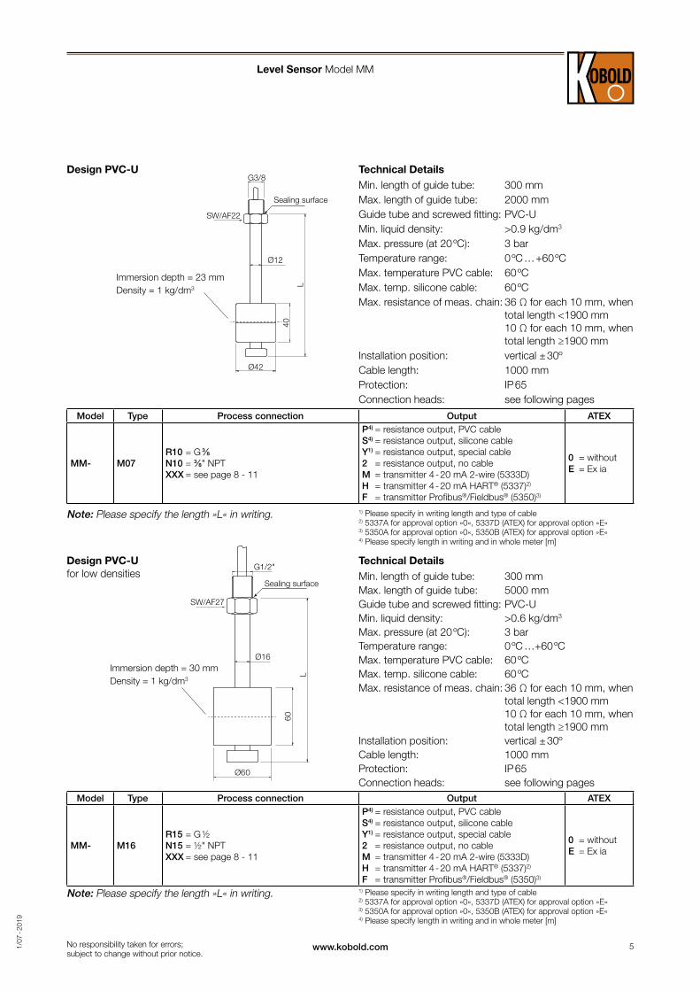
Technical DetailsMin. length of guide tube: 300 mmMax. length of guide tube: 2000 mmGuide tube and screwed fitting: PVC-UMin. liquid density: >0.9 kg/dm3
Max. pressure (at 20 ºC): 3 barTemperature range: 0 ºC … +60 ºCMax. temperature PVC cable: 60 ºCMax. temp. silicone cable: 60 ºCMax. resistance of meas. chain: 36 Ω for each 10 mm, when
total length <1900 mm 10 Ω for each 10 mm, when total length ≥1900 mm
Installation position: vertical ± 30ºCable length: 1000 mmProtection: IP 65Connection heads: see following pages
Technical DetailsMin. length of guide tube: 300 mmMax. length of guide tube: 5000 mmGuide tube and screwed fitting: PVC-UMin. liquid density: >0.6 kg/dm3
Max. pressure (at 20 ºC): 3 barTemperature range: 0 ºC …+60 ºCMax. temperature PVC cable: 60 ºCMax. temp. silicone cable: 60 ºCMax. resistance of meas. chain: 36 Ω for each 10 mm, when
total length <1900 mm 10 Ω for each 10 mm, when total length ≥1900 mm
Installation position: vertical ± 30ºCable length: 1000 mmProtection: IP 65Connection heads: see following pages
Immersion depth = 23 mm Density = 1 kg/dm3
Immersion depth = 30 mm Density = 1 kg/dm3
Design PVC-U
Design PVC-U for low densities
Model Type Process connection Output ATEX
MM- M07R10 = G ⅜N10 = ⅜" NPTXXX = see page 8 - 11
P4) = resistance output, PVC cableS4) = resistance output, silicone cableY1) = resistance output, special cable2 = resistance output, no cableM = transmitter 4 - 20 mA 2-wire (5333D)H = transmitter 4 - 20 mA HART® (5337)2)
F = transmitter Profibus®/Fieldbus® (5350)3)
0 = withoutE = Ex ia
Model Type Process connection Output ATEX
MM- M16R15 = G ½N15 = ½" NPTXXX = see page 8 - 11
P4) = resistance output, PVC cableS4) = resistance output, silicone cableY1) = resistance output, special cable2 = resistance output, no cableM = transmitter 4 - 20 mA 2-wire (5333D)H = transmitter 4 - 20 mA HART® (5337)2)
F = transmitter Profibus®/Fieldbus® (5350)3)
0 = withoutE = Ex ia
No responsibility taken for errors; subject to change without prior notice.
Note: Please specify the length »L« in writing. 1) Please specify in writing length and type of cable 2) 5337A for approval option »0«, 5337D (ATEX) for approval option »E« 3) 5350A for approval option »0«, 5350B (ATEX) for approval option »E« 4) Please specify length in writing and in whole meter [m]
Note: Please specify the length »L« in writing. 1) Please specify in writing length and type of cable 2) 5337A for approval option »0«, 5337D (ATEX) for approval option »E« 3) 5350A for approval option »0«, 5350B (ATEX) for approval option »E« 4) Please specify length in writing and in whole meter [m]
Sealing surface
Sealing surface
6 www.kobold.com 1/0
7 - 2
019
60
Ø38
10
Ø25
G3/8"
Ø16
L
G3/8"
52
Ø38
Ø12
L
SW/AF22
Level Sensor Model MM
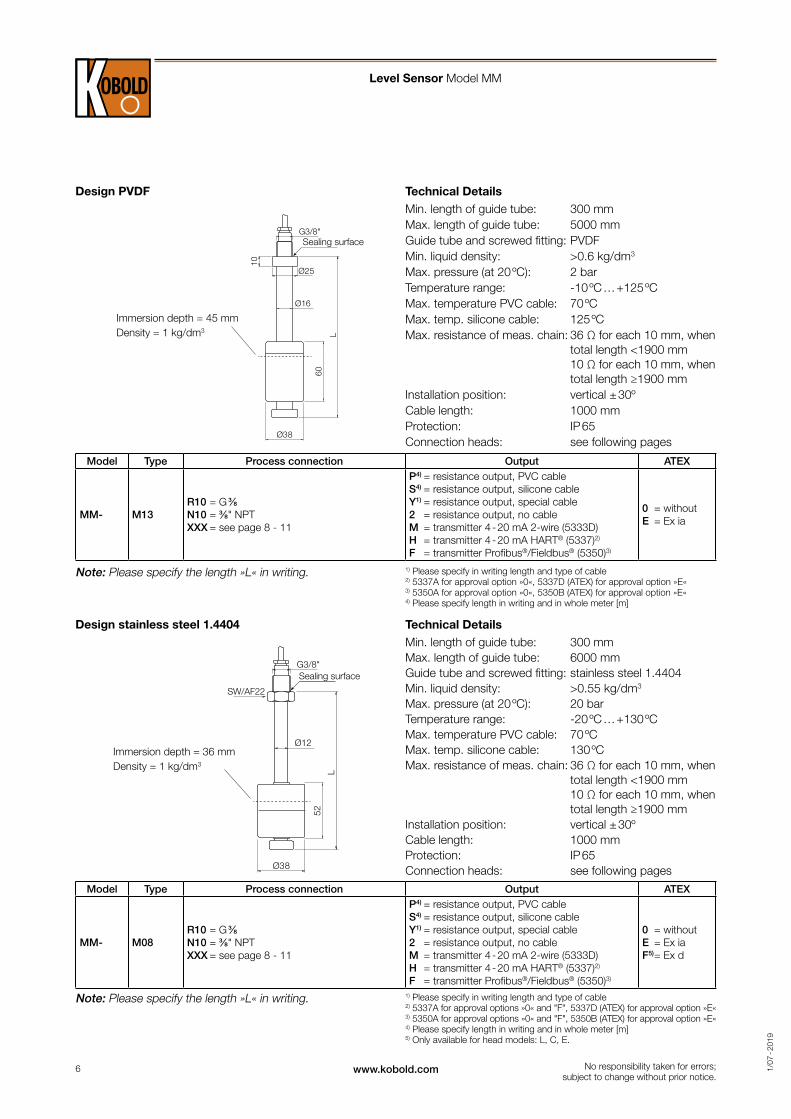
Technical DetailsMin. length of guide tube: 300 mmMax. length of guide tube: 5000 mmGuide tube and screwed fitting: PVDFMin. liquid density: >0.6 kg/dm3
Max. pressure (at 20 ºC): 2 barTemperature range: -10 ºC … +125 ºCMax. temperature PVC cable: 70 ºCMax. temp. silicone cable: 125 ºCMax. resistance of meas. chain: 36 Ω for each 10 mm, when
total length <1900 mm 10 Ω for each 10 mm, when total length ≥1900 mm
Installation position: vertical ± 30ºCable length: 1000 mmProtection: IP 65Connection heads: see following pages
Technical DetailsMin. length of guide tube: 300 mmMax. length of guide tube: 6000 mmGuide tube and screwed fitting: stainless steel 1.4404Min. liquid density: >0.55 kg/dm3
Max. pressure (at 20 ºC): 20 barTemperature range: -20 ºC … +130 ºCMax. temperature PVC cable: 70 ºCMax. temp. silicone cable: 130 ºCMax. resistance of meas. chain: 36 Ω for each 10 mm, when
total length <1900 mm 10 Ω for each 10 mm, when total length ≥1900 mm
Installation position: vertical ± 30ºCable length: 1000 mmProtection: IP 65Connection heads: see following pages
Design PVDF
Design stainless steel 1.4404
Model Type Process connection Output ATEX
MM- M13R10 = G ⅜N10 = ⅜" NPTXXX = see page 8 - 11
P4) = resistance output, PVC cableS4) = resistance output, silicone cableY1) = resistance output, special cable2 = resistance output, no cableM = transmitter 4 - 20 mA 2-wire (5333D)H = transmitter 4 - 20 mA HART® (5337)2)
F = transmitter Profibus®/Fieldbus® (5350)3)
0 = withoutE = Ex ia
Model Type Process connection Output ATEX
MM- M08R10 = G ⅜N10 = ⅜" NPTXXX = see page 8 - 11
P4) = resistance output, PVC cableS4) = resistance output, silicone cableY1) = resistance output, special cable2 = resistance output, no cableM = transmitter 4 - 20 mA 2-wire (5333D)H = transmitter 4 - 20 mA HART® (5337)2)
F = transmitter Profibus®/Fieldbus® (5350)3)
0 = withoutE = Ex iaF5) = Ex d
No responsibility taken for errors; subject to change without prior notice.
Immersion depth = 45 mm Density = 1 kg/dm3
Immersion depth = 36 mm Density = 1 kg/dm3
Note: Please specify the length »L« in writing. 1) Please specify in writing length and type of cable 2) 5337A for approval option »0«, 5337D (ATEX) for approval option »E« 3) 5350A for approval option »0«, 5350B (ATEX) for approval option »E« 4) Please specify length in writing and in whole meter [m]
Note: Please specify the length »L« in writing. 1) Please specify in writing length and type of cable 2) 5337A for approval options »0« and "F", 5337D (ATEX) for approval option »E« 3) 5350A for approval options »0« and "F", 5350B (ATEX) for approval option »E« 4) Please specify length in writing and in whole meter [m] 5) Only available for head models: L, C, E.
Sealing surface
Sealing surface

7www.kobold.com 1/0
7 - 2
019
G3/8"
Ø52
52Ø12
L
SW/AF22
95
Ø95
G1/2"
Ø18
SW/AF27
L
Level Sensor Model MM
Technical DetailsMin. length of guide tube: 300 mmMax. length of guide tube: 6000 mmGuide tube and screwed fitting: stainless steel 1.4404Min. liquid density: >0.6 kg/dm3
Max. pressure (at 20 ºC): 30 barTemperature range: -20 ºC … +130 ºCMax. temperature PVC cable: 70 ºCMax. temp. silicone cable: 130 ºCMax. resistance of meas. chain: 36 Ω for each 10 mm, when
total length <1900 mm 10 Ω for each 10 mm, when total length ≥1900 mm
Installation position: vertical ± 30ºCable length: 1000 mmProtection: IP 65Connection heads: see following pages
Technical DetailsMin. length of guide tube: 300 mmMax. length of guide tube: 6000 mmGuide tube and screwed fitting: stainless steel 1.4404Min. liquid density: >0.5 kg/dm3
Max. pressure (at 20 ºC): 15 barTemperature range: -20 ºC … +130 ºCMax. temperature PVC cable: 70 ºCMax. temp. silicone cable: 130 ºCMax. resistance of meas. chain: 36 Ω for each 10 mm, when
total length <1900 mm 10 Ω for each 10 mm, when total length ≥1900 mm
Installation position: vertical ± 30ºCable length: 1000 mmProtection: IP 65Connection heads: see following pages
Design stainless steel 1.4404
for high pressure
Design stainless steel 1.4404 for low densities
Model Type Process connection Output ATEX
MM- M10R10 = G ⅜N10 = ⅜" NPTXXX = see page 8 - 11
P4) = resistance output, PVC cableS4) = resistance output, silicone cableY1) = resistance output, special cable2 = resistance output, no cableM = transmitter 4 - 20 mA 2-wire (5333D)H = transmitter 4 - 20 mA HART® (5337)2)
F = transmitter Profibus®/Fieldbus® (5350)3)
0 = withoutE = Ex iaF5) = Ex d
Model Type Process connection Output ATEX
MM- M20R15 = G ½N15 = ½" NPTXXX = see page 8 - 11
P4) = resistance output, PVC cableS4) = resistance output, silicone cableY1) = resistance output, special cable2 = resistance output, no cableM = transmitter 4 - 20 mA 2-wire (5333D)H = transmitter 4 - 20 mA HART® (5337)2)
F = transmitter Profibus®/Fieldbus® (5350)3)
0 = withoutE = Ex iaF5) = Ex d
No responsibility taken for errors; subject to change without prior notice.
Immersion depth = 31 mm Density = 1 kg/dm3
Immersion depth = 48 mm Density = 1 kg/dm3
Note: Please specify the length »L« in writing. 1) Please specify in writing length and type of cable 2) 5337A for approval options »0«and "F", 5337D (ATEX) for approval option »E« 3) 5350A for approval options »0« and "F", 5350B (ATEX) for approval option »E« 4) Please specify length in writing and in whole meter [m] 5) Only available for head models: L, C, E.
Note: Please specify the length »L« in writing.1) Please specify in writing length and type of cable 2) 5337A for approval options »0«and "F", 5337D (ATEX) for approval option »E« 3) 5350A for approval options »0« and "F", 5350B (ATEX) for approval option »E« 4) Please specify length in writing and in whole meter [m] 5) Only available for head models: L, C, E.
Sealing surface
Sealing surface

8 www.kobold.com 1/0
7 - 2
019
F
C
B
E
A
D
C
B
E
A
DF
C
B
E
A
DF
Connection Heads Model MM
No responsibility taken for errors; subject to change without prior notice.
PP screwed cover housingDimensions and materials
Model Process connection
(A)1)
Width across flats (B)
Electrical connection
(C)
Overall height
(D)
Screwed fitting
(E)
Thread length3)
(F)
tmax
1
R8 = G 1½ 30 AF
PG16100 mm
PP
22 mm
90 ºC2)R9 = G 2 36 AF 24 mm
N8 = 1½" NPT 30 AF 25 mm
N9 = 2" NPT 36 AF 27 mm
1) Size of process connection must be according with float size 2) Max. temperature 85°C if transmitter output is selected 3) Length »L« includes thread length
PA screwed cover housingDimensions and materials
Model Process connection
(A)1)
Width across flats (B)
Electrical connection
(C)
Overall height
(D)
Screwed fitting
(E)
Thread length3)
(F)
tmax
3
R8 = G 1½ 30 AF
M16 x 1.5104 mm
1.4404
22 mm
90 ºC2)R9 = G 2 36 AF 24 mm
N8 = 1½" NPT 30 AF 25 mm
N9 = 2" NPT 36 AF 27 mm
1) Size of process connection must be according with float size 2) Max. temperature 85°C if transmitter output is selected 3) Length »L« includes thread length
Aluminium housingDimensions and materials
Model Process connection
(A)1)
Width across flats (B)
Electrical connection
(C)
Overall height
(D)
Screwed fitting
(E)
Thread length3)
(F)
tmax
4
R8 = G 1½ 30 AF
M16 x 1.5 73 mm 1.4404
22 mm
90 ºC2)R9 = G 2 36 AF 24 mm
N8 = 1½" NPT 30 AF 25 mm
N9 = 2" NPT 36 AF 27 mm
1) Size of process connection must be according with float size 2) Max. temperature 85°C if transmitter output is selected 3) Length »L« includes thread length
Model 1
Model 3
Model 4

9www.kobold.com 1/0
7 - 2
019
B
E
A
D
C
F
C
B
E
A
DF
C
B
E
A
DF
Connection Heads Model MM
No responsibility taken for errors; subject to change without prior notice.
ABS housingDimensions and materials
Model Process connection
(A)1)
Width across flats (B)
Electrical connection
(C)
Overall height
(D)
Screwed fitting
(E)
Thread length2)
(F)
tmax
5
R8 = G 1½ 30 AF
M16 x 1.5 100 mm PVC
22 mm
60 ºCR9 = G 2 36 AF 24 mm
N8 = 1½" NPT 30 AF 25 mm
N9 = 2" NPT 36 AF 27 mm
1) Size of process connection must be according with float size 2) Length »L« includes thread length
PA screwed cover housingDimensions and materials
Model Process connection
(A)1)
Width across flats (B)
Electrical connection
(C)
Overall height
(D)
Screwed fitting
(E)
Thread length3)
(F)
tmax
6R8 = G 1½
30 AF M16 x 1.5104 mm
PVDF22 mm
90 ºC2)
N8 = 1½" NPT 25 mm
1) Size of process connection must be according with float size 2) Max. temperature 85°C if transmitter output is selected 3) Length »L« includes thread length
Connector with connecting boxDimensions and materials
Model2) Process connection
(A)1)
Width across flats (B)
Electrical connection
(C)
Overall height
(D)
Screwed fitting
(E)
Thread length3)
(F)
tmax
7 (3-pin)
R8 = G 1½ 30 AF
M16 x 1.5 65 mm PP
22 mm
90 ºCR9 = G 2 36 AF 24 mm
N8 = 1½" NPT 30 AF 25 mm
N9 = 2" NPT 36 AF 27 mm
1) Size of process connection must be according with float size 2) To be chosen only with resistance output 3) Length »L« includes thread length
Model 5
Model 6
Model 7

10 www.kobold.com 1/0
7 - 2
019
F
54
LKØ
D
b
d1
C
B
E
A
DF
B
E
A
DF
LDK
OBO
E
LOOP POWERED INDICATOR
Connection Heads Model MM
No responsibility taken for errors; subject to change without prior notice.
Flange according to DIN EN 1092-1 PN16 / ANSI B 16.5 150 lbs RFDimensions and materials
Model Flange size 1.44041)
D b LKØ d1 Electrical connection
(C)
Housing (F)
tmax
9
F9 = DN 50 165 18 125 4 x Ø18
M16 x 1.5 Al 90 ºC2)
F0 = DN 65 185 18 145 4 x Ø18FB = DN 80 200 20 160 4 x Ø18FC = DN 100 220 20 180 8 x Ø18FD = DN 125 250 22 210 8 x Ø18A8 = 1½" 127 17.5 98.6 4 x Ø15.7A9 = 2" 152.4 19.1 120.7 4 x Ø19.1A0 = 2½" 177.8 22.4 139.7 4 x Ø19.1AB = 3" 190.5 23.9 152.4 4 x Ø19.1AC = 4" 228.6 23.9 190.5 8 x Ø19.1
1) Other materials on request (PP, PVDF, PVC-U) 2) Max. temperature 85°C if transmitter output is selected
Aluminium housing, for application ATEX II GD Ex d IIC T1 ... T6Dimensions and materials
Model Process connection
(A)1)
Width across flats (B)
Electrical connection
(C)
Overall height
(D)
Screwed fitting
(E)
Thread length2)
(F)
tmax
L
R8 = G 1½ 30 AF
M20 145 mm 1.4404
22 mm
90 ºCR9 = G 2 36 AF 24 mm
N8 = 1½" NPT 30 AF 25 mm
N9 = 2" NPT 36 AF 27 mm
1) Size of process connection must be according with float size 2) Length »L« includes thread length
Aluminium housing with display for applications ATEX II GD Ex d IIC T1 ... T6Dimensions and materials
Model1) Process connection
(A)2)
Width across flats (B)
Electrical connection
(C)
Overall height
(D)
Screwed fitting
(E)
Thread length3)
(F)
tmax
C (LCD
display)
R8 = G 1½ 30 AF
M20 155 mm 1.4404
22 mm
70 ºCR9 = G 2 36 AF 24 mm
N8 = 1½" NPT 30 AF 25 mm
N9 = 2" NPT 36 AF 27 mm
E (LED
display)
R8 = G 1½ 30 AF 22 mm
80 ºCR9 = G 2 36 AF 24 mm
N8 = 1½" NPT 30 AF 25 mm
N9 = 2" NPT 36 AF 27 mm
1) Only with 4 ... 20 mA transmitter. Loop powered display
2) Size of pro cess connection must be according with float size 3) Length »L« includes thread length
Model 9
Model L
Model C/E

11www.kobold.com 1/0
7 - 2
019
C
B
E
A
D
78.8%
FConnection Heads Model MM
No responsibility taken for errors; subject to change without prior notice.
Stainless steel 1.4404 head with touch screen LCD displayDimensions and materials
Model1) Process connection
(A)2)
Width across flats (B)
Electrical connection
(C)
Overall height
(D)
Screwed fitting
(E)
Thread length3)
(F)
tmax
D
R8 = G 1½ SW 30
M16 x 1,5 112 mm 1.4404
22 mm
80 ºC
R9 = G 2 SW 36 24 mm
N8 = 1½" NPT SW 30 25 mm
N9 = 2" NPT SW 36 27 mm
R (with
2 relay output)
R8 = G 1½ SW 30 22 mm
R9 = G 2 SW 36 24 mm
N8 = 1½" NPT SW 30 25 mm
N9 = 2" NPT SW 36 27 mm
1) Only with 4 ... 20 mA transmitter. Loop powered display
2) Size of pro cess connection must be according with float size 3) Length »L« includes thread length
Model D/R

12 www.kobold.com 1/0
7 - 2
019
No responsibility taken for errors; subject to change without prior notice.
Level Sensor Model MM
Heads selector for Magnetic level MM series. Direct connection
Heads M05 Ø42 mm
M07 Ø40 mm
M08 Ø38 mm
M10 Ø52 mm
M13 Ø38 mm
M15 Ø60 mm
M16 Ø60 mm
M20 Ø95 mm
1R8 x x x x
1R9 x x x x x
1N8 x x x x
1N9 x x x x x
3R8 x x x x
3R9 x x x x x
3N8 x x x x
3N9 x x x x x
4R8 x x x x
4R9 x x x x x
4N8 x x x x
4N9 x x x x x
5R8 x x x x
5R9 x x x x x
5N8 x x x x
5N9 x x x x x
6R8 x x x x
6N8 x x x x
7R8 x x x x
7R9 x x x x x
7N8 x x x x
7N9 x x x x x
LR8 x x x x
LR9 x x x x x
LN8 x x x x
LN9 x x x x x
CR8 x x x x
CR9 x x x x x
CN8 x x x x
CN9 x x x x x
ER8 x x x x
ER9 x x x x x
EN8 x x x x
EN9 x x x x x
DR8 x x x x
DR9 x x x x x
DN8 x x x x
DN9 x x x x x
RR8 x x x x
RR9 x x x x x
RN8 x x x x
RN9 x x x x x

13www.kobold.com 1/0
7 - 2
019
No responsibility taken for errors; subject to change without prior notice.
Level Sensor Model MM
Heads Selector for Magnetic Level MM Series. Direct connection (continued)
Heads M05 Ø42 mm
M07 Ø40 mm
M08 Ø38 mm
M10 Ø52 mm
M13 Ø38 mm
M15 Ø60 mm
M16 Ø60 mm
M20 Ø95 mm
For flanged connection, please ensure that float diameter is less than flange hole diameter!
9F8 x x
9F9 x x x x x
9F0 x x x x x x x
9FB x x x x x x x
9FC x x x x x x x x
9FD x x x x x x x x
9A8 x x x x x
9A9 x x x x x
9A0 x x x x x x x
9AB x x x x x x x
9AV x x x x x x x x
9AC x x x x x x x x
Important note: Float may be removed in all models of the MM series!