Embed Size (px)
Citation preview

KSR data sheet FFG-P, FFG-T, FFG-TP, FLM-H
Page 1 of 9
A division of the WIKA Group
®
Level sensorMagnetostrictive, high-resolution measuring principleModels FFG-P, FFG-T, FFG-TP, FLM-H
Data sheets showing similar products:Level sensor, with reed chain technology; see model FLR
Applications
■ High-accuracy level measurement for almost all liquid media
■ Chemical, petrochemical, natural gas, off shore, shipbuilding, machine building, power generating equipment, power plants
■ Process water and drinking water treatment, food industry, pharmaceutical industry
Special features
■ Process- and system-specifi c solutions possible ■ Operating limits:
- Operating temperature: T = -90 ... +400 °C- Operating pressure: P = Vacuum to 100 bar- Limit density: ρ ≥ 400 kg/m3
■ Resolution < 0.1 mm ■ Wide variety of diff erent electrical connections, process
connections and materials ■ Explosion-protected versions
DescriptionThe model FFG-P, FFG-T, FFG-TP and FLM-H sensors are used for the high-accuracy, continuous level measurement of liquids and are based on determining the position of a magnetic fl oat according to the magnetostrictive measuring principle.
Level measurement
Level sensorModel FFG-T, fl ange connection
Model DescriptionFFG-P Standard versionFFG-T High-temperature versionFFG-TP Plastic versionFLM-H Sterile version
KSR data sheet LM 20.01 ∙ 09/2015

Page 2 of 9 KSR data sheet LM 20.01 ∙ 09/2015
Further special features
■ Large scope of application due to the simple, proven functional principle
■ Process connection, guide tube and float from stainless steel 1.4571, 1.4435, 1.4539 or plastic
■ For harsh operating conditions, long service life ■ Continuous measurement of levels, independent of
physical and chemical changes of the media such as: Foaming, conductivity, dielectric constant, pressure, vacuum, temperature, vapours, condensation, bubble formation, boiling effects, density change
■ Signal transmission over long distances ■ Simple installation and commissioning, onetime
calibration only, no recalibration necessary. ■ Level displayed proportional to volume or height ■ Parallel measurement of interface layer and overall level
possible via HART® interface
Options
■ Customised solutions ■ Process connection, guide tube material and float from
special steel, titanium, Hastelloy (others on request) ■ In combination with limit switch, stepless setting of the
limit values over the entire measuring range
Illustration of the principle
Design and operating principle
■ The measuring process is triggered by a current impulse. This current produces a circular magnetic field (3) along a wire (1) made of magnetostrictive material fixed in the guide tube.
■ At the point being measured (liquid level) there is a float with permanent magnets (4) acting as a position transducer.
■ The interaction of both magnetic fields generates a mechanical torsion wave (5) in the wire.
■ This is converted into an electrical signal at the end of the wire in the sensor housing (2) by a piezoceramic converter.
■ The measured propagation delay enables the origination point, and thus the float position, to be determined with high accuracy.
2
53
4
1
5
Legend1 Wire2 Sensor housing3 Magnetic field4 Permanent
magnet5 Torsional wave

KSR data sheet LM 20.01 ∙ 09/2015 Page 3 of 9
Product overview
Sensor model
Aproval (Option)without Ex i Ex d 3A
FFG-P x x xFFG-T x xFLM-H x x
Sensor model
Description Materials Temperature range(process)Stainless
steel 1.4571 (316Ti)
Stainless steel 1.4404 (316L)
Titanium 3.7035 (grade 2)
Stainless steel 1.4435 (316L)
PP PVDF
FFG-P Magnetostrictive sensor, standard
x x x -60 ... +185 °C
FFG-T Magnetostrictive sensor, high temperature
x x x -90 ... +400 °C
FFG-TP Magnetostrictive sensor, plastic
x x -10 ... +100 °C
FLM-H Magnetostrictive sensor, sterile version
x x -40 ... +400 °C
Type approvalApproval Model Approval numberEAC-Ex FFG-. RU C-DE.GB08.B.00845
EAC FFG-. TC N RU D-DE.AU14.B.215323A FLM-H 3-A Sanitary Standards 74-06
Ex approvalsExplosion protection
Ignition protec-tion type
Model Zone Approval number
ATEX Ex i FFG-T-Ex i Zone 0 IBExU 02 ATEX 1124 X II 1/2G Ex ia IIC T3 ... T6Ex i FFG-P.22H2... Zone 0 ZELM 10 ATEX 0439 II 1/2G Ex ia IIC T3 ... T6Ex d FFG-P.22H3... Zone 1 ZELM 13 ATEX 0508 X II 1/2G Ex d IIB T3 to T6 Ga Gb

Page 4 of 9 KSR data sheet LM 20.01 ∙ 09/2015
Sensor, standard, model FFG-PProcess connection, guide tube and float from stainless steel 1.4571
Mounting thread FlangeElectrical connection Sensor housing, material stainless steel 1.4404 (316L)
Version FFG-PN without displayVersion FFG-PD with window and display
Display LCD matrix (only version FFG-PD)
Process connection Mounting threaddownwardsG 1 1/2 or G 2
Mounting flange DIN DN 50 ... DN 200, PN 6 ... PN 100 ANSI 2" ... 8", class 150 ... 600
Guide tube diameter 14 mm 18 mm 14 mm 18 mmGuide tube length L max. 3,000 mm 5,800 mm 3,000 mm 5,800 mmFloat Material stainless steel 1.4571 (option: Titanium)
Float diameter from 44 ... 120 mmFloat selection depending on guide tube diameter and process conditions (see page 8)Attention: With Ex approval no floats from titanium may be used.
Max. operating pressure 40 bar (100 bar with float from titanium), see table on page 8Temperature rangeStandard Medium: -60 ... +185 °C
Ambient temperature:- Standard, version without display -40 ... +85 °C- Standard, version with display -20 ...+70 °C- Version Ex i T3/T4/T5: -20 °C ... +70 °C, T6: -20 °C ... +60 °C- Version Ex d T3/T4/T5: -20 °C ... +70 °C, T6: -20 °C ... +60 °C
Output signal 4 ... 20 mA, HART®
Power supply DC 15 ... 30 VMeasuring accuracy < ±0.5 mmResolution < 0.1 mmLoad max. 900 Ω at 30 VMounting position Vertical ±30°Ingress protection IP 67 per EN 60529 / lEC 60529
Flange
Case with display (version FFG-PD)
Float
Case without display (version FFG-PN)
Float

KSR data sheet LM 20.01 ∙ 09/2015 Page 5 of 9
Gui
de tu
be le
ngth
L =
...
Gui
de tu
be le
ngth
L =
...
Mounting thread FlangeElectrical connection Sensor housing, material stainless steel 1.4301Process connection Mounting thread
downwardsG 1 1/2 or G 2
Mounting flange DIN DN 50 ... DN 200, PN 6 ... PN 100 ANSI 2" ... 8", class 150 ... 600
Guide tube diameter 12 mm 18 mm 12 mm 18 mmGuide tube length L max.
3,000 mm 6,000 mm 3,000 mm 6,000 mm
Float Material stainless steel 1.4571 (option: Titanium)Float diameter from 44 ... 120 mmFloat selection depending on guide tube diameter and process conditions (see page 8)
Max. operating pressure 40 bar (100 bar with float from titanium), see table on page 8Temperature rangeStandard Medium:
- Version FFG-TH: -45 ... +400 °C- Version FFG-TT: -90 ... +125 °CAmbient temperature: -40 ... +85 °C
Output signal 4 ... 20 mA, HART®
Power supply DC 10 ... 30 VMeasuring accuracy < ±0.5 mmResolution < 0.1 mmLoad max. 900 Ω at 30 VMounting position Vertical ±30°Ingress protection IP 68 per EN 60529 / lEC 60529
SW 30 or SW 36
Sensor housing
Mea
surin
g ra
nge
M 100 % display
Guide tube Ø 12 or 18 mmFloat
7012
0
Ø 52
Cable gland M16 x 1.5
Mounting flange
100 % display
Guide tube Ø 12 or 18 mmFloat
Ø 52
120
Float Ø Float ØM
easu
ring
rang
e M
Sensor housing
L1 =
...
L1 =
...
70
Sensor, high temperature, model FFG-TProcess connection, guide tube and float from stainless steel 1.4571
Cable gland M16 x 1.5
G 1 1/2 / G 2
Page 6 of 9 KSR data sheet LM 20.01 ∙ 09/2015
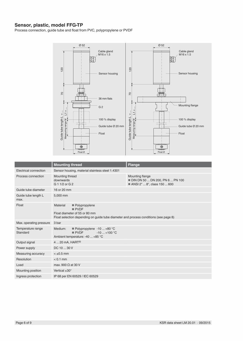
Mounting thread FlangeElectrical connection Sensor housing, material stainless steel 1.4301Process connection Mounting thread
downwardsG 1 1/2 or G 2
Mounting flange DIN DN 50 ... DN 200, PN 6 ... PN 100 ANSI 2" ... 8", class 150 ... 600
Guide tube diameter 16 or 20 mmGuide tube length L max.
5,000 mm
Float Material Polypropylene PVDFFloat diameter of 55 or 80 mmFloat selection depending on guide tube diameter and process conditions (see page 8)
Max. operating pressure 3 barTemperature rangeStandard
Medium: Polypropylene -10 ... +80 °C PVDF -10 ... +100 °CAmbient temperature: -40 ... +85 °C
Output signal 4 ... 20 mA, HART®
Power supply DC 10 ... 30 VMeasuring accuracy < ±0.5 mmResolution < 0.1 mmLoad max. 900 Ω at 30 VMounting position Vertical ±30°Ingress protection IP 68 per EN 60529 / lEC 60529
Sensor, plastic, model FFG-TPProcess connection, guide tube and float from PVC, polypropylene or PVDF
Gui
de tu
be le
ngth
L =
...
Gui
de tu
be le
ngth
L =
...
36 mm flats
Sensor housing
Mea
surin
g ra
nge
M
G 2
100 % display
Guide tube Ø 20 mm
Float
7012
0
Ø 52
Mounting flange
100 % display
Guide tube Ø 20 mm
Float
Ø 52
120
Float Ø
Mea
surin
g ra
nge
M
Sensor housing
Float Ø
L1 =
...
L1 =
...
Cable gland M16 x 1.5
Cable gland M16 x 1.5
70

KSR data sheet LM 20.01 ∙ 09/2015 Page 7 of 9
L ...
L ...
Sensor, sterile version, model FLM-HProcess connection, guide tube and float from stainless steel 1.4435 (316L) or 1.4404 (316L), surface ground and polished Ra < 0.8 μm or Ra < 0.4 μm, alternatively electropolished
Version without floor fixture Version with separate floor fixtureElectrical connection Sensor housing, material stainless steel 1.4305Process connection Clamp ISO 2852
Clamp DIN 32767Aseptic thread DIN 11864-1Aseptic collar connecting sleeve DIN 11864-1Aseptic flange DIN 11864-2Aseptic clamp DIN 11864-3VARIVENTBioConnect
Guide tube diameter 17.2 mmGuide tube length L max.
6,000 mm
Float Material stainless steel 1.4435 (316L) or 1.4539 (316L)Float diameter of 80 mmFloat selection depending on guide tube diameter and process conditions (see page 8)
Max. operating pressure 10 barTemperature rangeStandard Medium:
- Standard, version FLM-H: -40 ... +250 °C- High temperature, version FLM-HT: -40 ...+400 °CAmbient temperature: -40 ... +85 °C
Output signal 4 ... 20 mA, HART®
Power supply DC 10 ... 30 VMeasuring accuracy < ±0.5 mmResolution < 0.1 mmLoad max. 900 Ω at 30 VMounting position Vertical ±30°Ingress protection IP 68 per EN 60529 / lEC 60529
Cable gland M16 x 1.5
®
Sensor housing
Clamp pipe connection
Float
Guide tube
Cable gland M16 x 1.5
Sensor housing
Clamp pipe connection
Float
Guide tube
Page 8 of 9 KSR data sheet LM 20.01 ∙ 09/2015
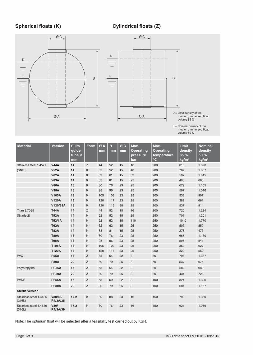
Spherical floats (K) Cylindrical floats (Z)
Note: The optimum float will be selected after a feasibility test carried out by KSR.
Ø C Ø C
D
E
D
EB B
Ø A Ø A
Material Version Suits guide tube Ømm
Form Ø Amm
Bmm
Ø Cmm
Max. Operating pressurebar
Max. Operating temperature°C
Limit density 85 %kg/m3
Nominal density 50 %kg/m3
Stainless steel 1.4571 V44A 14 Z 44 52 15 16 200 818 1.390(316Ti) V52A 14 K 52 52 15 40 200 769 1.307
V62A 14 K 62 61 15 32 200 597 1.015V83A 14 K 83 81 15 25 200 408 693V80A 18 K 80 76 23 25 200 679 1.155V98A 18 K 98 96 23 25 200 597 1.016V105A 18 K 105 103 23 25 200 533 907V120A 18 K 120 117 23 25 200 389 661V120/38A 18 K 120 116 38 25 200 537 914
Titan 3.7035 T44A 14 Z 44 52 15 16 200 720 1.224(Grade 2) T52A 14 K 52 52 15 25 250 707 1.201
T52/1A 14 K 52 52 15 110 250 1040 1.770T62A 14 K 62 62 15 25 250 505 859T83A 14 K 83 81 15 25 250 278 473T80A 18 K 80 76 23 25 250 665 1.130T98A 18 K 98 96 23 25 250 595 841T105A 18 K 105 103 23 25 250 369 627T120A 18 K 120 117 23 25 250 329 560
PVC P55A 16 Z 55 54 22 3 60 798 1.357
P80A 20 Z 80 79 25 3 60 537 974
Polypropylen PP55A 16 Z 55 54 22 3 80 582 989
PP80A 20 Z 80 79 25 3 80 431 723
PVDF PF55A 16 Z 55 69 22 3 100 821 1.396
PF80A 20 Z 80 79 25 3 100 681 1.157Sterile version
Stainless steel 1.4435 (316L)
V80/88/R4/3A/35
17.2 K 80 88 23 16 150 790 1.350
Stainless steel 1.4539 (316L)
V80/R4/3A/39
17.2 K 80 76 23 16 150 621 1.056
D = Limit density of the medium, immersed float volume 85 %
E = Nominal density of the medium, immersed float volume 50 %

KSR data sheet LM 20.01 ∙ 09/2015 Page 9 of 9
09/2
015
EN
A division of the WIKA Group
KSR KUEBLER Niveau-Messtechnik AGHeinrich-Kuebler-Platz 169439 Zwingenberg/GermanyTel. +49 6263 87-0Fax +49 6263 [email protected]
Ordering informationModel / Version / Electrical connection / Process connection / Guide tube diameter / Guide tube length (insertion length) L / 100 % mark L1 / Measuring range M (span 0 % - 100 %) / Process specifications (operating temperature and pressure, limit density) / Options
© 2014 KSR KUEBLER Niveau-Messtechnik AG, all rights reserved.The specifications given in this document represent the state of engineering at the time of publishing.We reserve the right to make modifications to the specifications and materials.