Embed Size (px)
Citation preview
Achromatic Metasurface Lens at Telecommunication WavelengthsMohammadreza Khorasaninejad,† Francesco Aieta,†,‡ Pritpal Kanhaiya,†,§ Mikhail A. Kats,†,∥
Patrice Genevet,†,⊥ David Rousso,†,§ and Federico Capasso*,†
†School of Engineering and Applied Sciences, Harvard University, Cambridge, Massachusetts 02138, United States‡Hewlett-Packard Laboratories, Palo Alto, California 94304, United States§University of Waterloo, Waterloo, ON N2L 3G1, Canada∥Department of Electrical and Computer Engineering, University of WisconsinMadison, Madison, Wisconsin 53706, United States⊥Singapore Institute of Manufacturing Technology, 71 Nanyang Drive, Singapore 638075, Singapore
*S Supporting Information
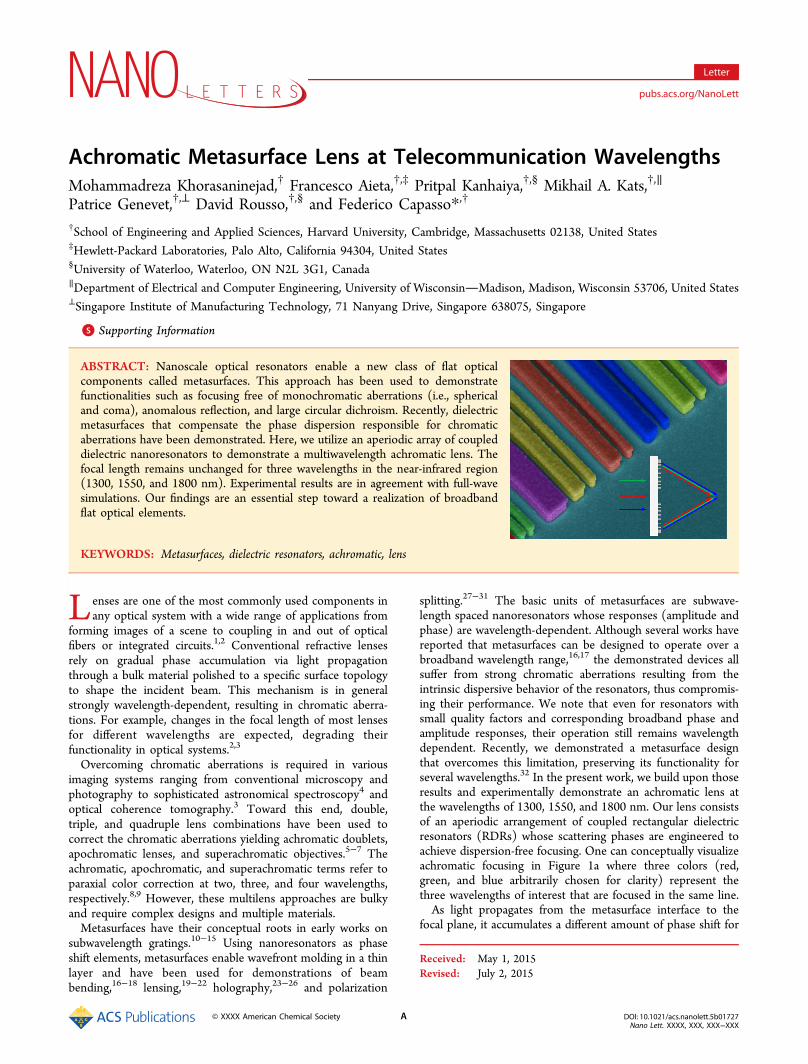
ABSTRACT: Nanoscale optical resonators enable a new class of flat opticalcomponents called metasurfaces. This approach has been used to demonstratefunctionalities such as focusing free of monochromatic aberrations (i.e., sphericaland coma), anomalous reflection, and large circular dichroism. Recently, dielectricmetasurfaces that compensate the phase dispersion responsible for chromaticaberrations have been demonstrated. Here, we utilize an aperiodic array of coupleddielectric nanoresonators to demonstrate a multiwavelength achromatic lens. Thefocal length remains unchanged for three wavelengths in the near-infrared region(1300, 1550, and 1800 nm). Experimental results are in agreement with full-wavesimulations. Our findings are an essential step toward a realization of broadbandflat optical elements.
KEYWORDS: Metasurfaces, dielectric resonators, achromatic, lens
Lenses are one of the most commonly used components inany optical system with a wide range of applications from
forming images of a scene to coupling in and out of opticalfibers or integrated circuits.1,2 Conventional refractive lensesrely on gradual phase accumulation via light propagationthrough a bulk material polished to a specific surface topologyto shape the incident beam. This mechanism is in generalstrongly wavelength-dependent, resulting in chromatic aberra-tions. For example, changes in the focal length of most lensesfor different wavelengths are expected, degrading theirfunctionality in optical systems.2,3
Overcoming chromatic aberrations is required in variousimaging systems ranging from conventional microscopy andphotography to sophisticated astronomical spectroscopy4 andoptical coherence tomography.3 Toward this end, double,triple, and quadruple lens combinations have been used tocorrect the chromatic aberrations yielding achromatic doublets,apochromatic lenses, and superachromatic objectives.5−7 Theachromatic, apochromatic, and superachromatic terms refer toparaxial color correction at two, three, and four wavelengths,respectively.8,9 However, these multilens approaches are bulkyand require complex designs and multiple materials.Metasurfaces have their conceptual roots in early works on
subwavelength gratings.10−15 Using nanoresonators as phaseshift elements, metasurfaces enable wavefront molding in a thinlayer and have been used for demonstrations of beambending,16−18 lensing,19−22 holography,23−26 and polarization
splitting.27−31 The basic units of metasurfaces are subwave-length spaced nanoresonators whose responses (amplitude andphase) are wavelength-dependent. Although several works havereported that metasurfaces can be designed to operate over abroadband wavelength range,16,17 the demonstrated devices allsuffer from strong chromatic aberrations resulting from theintrinsic dispersive behavior of the resonators, thus compromis-ing their performance. We note that even for resonators withsmall quality factors and corresponding broadband phase andamplitude responses, their operation still remains wavelengthdependent. Recently, we demonstrated a metasurface designthat overcomes this limitation, preserving its functionality forseveral wavelengths.32 In the present work, we build upon thoseresults and experimentally demonstrate an achromatic lens atthe wavelengths of 1300, 1550, and 1800 nm. Our lens consistsof an aperiodic arrangement of coupled rectangular dielectricresonators (RDRs) whose scattering phases are engineered toachieve dispersion-free focusing. One can conceptually visualizeachromatic focusing in Figure 1a where three colors (red,green, and blue arbitrarily chosen for clarity) represent thethree wavelengths of interest that are focused in the same line.As light propagates from the metasurface interface to the
focal plane, it accumulates a different amount of phase shift for
Received: May 1, 2015Revised: July 2, 2015
Letter
pubs.acs.org/NanoLett
© XXXX American Chemical Society A DOI: 10.1021/acs.nanolett.5b01727Nano Lett. XXXX, XXX, XXX−XXX
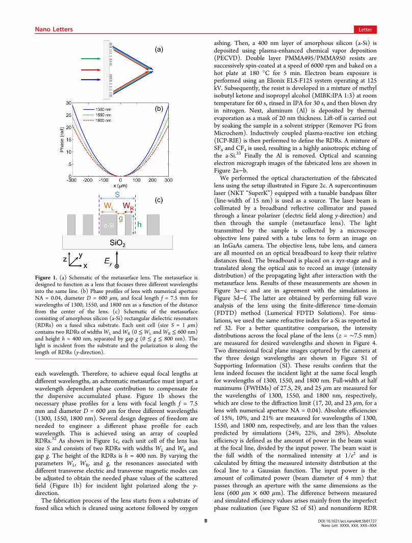
each wavelength. Therefore, to achieve equal focal lengths atdifferent wavelengths, an achromatic metasurface must impart awavelength dependent phase contribution to compensate forthe dispersive accumulated phase. Figure 1b shows thenecessary phase profiles for a lens with focal length f = 7.5mm and diameter D = 600 μm for three different wavelengths(1300, 1550, 1800 nm). Several design degrees of freedom areneeded to engineer a different phase profile for eachwavelength. This is achieved using an array of coupledRDRs.32 As shown in Figure 1c, each unit cell of the lens hassize S and consists of two RDRs with widths WL and WR andgap g. The height of the RDRs is h = 400 nm. By varying theparameters WL, WR, and g, the resonances associated withdifferent transverse electric and transverse magnetic modes canbe adjusted to obtain the needed phase values of the scatteredfield (Figure 1b) for incident light polarized along the y-direction.The fabrication process of the lens starts from a substrate of
fused silica which is cleaned using acetone followed by oxygen
ashing. Then, a 400 nm layer of amorphous silicon (a-Si) isdeposited using plasma-enhanced chemical vapor deposition(PECVD). Double layer PMMA495/PMMA950 resists aresuccessively spin-coated at a speed of 6000 rpm and baked on ahot plate at 180 °C for 5 min. Electron beam exposure isperformed using an Elionix ELS-F125 system operating at 125kV. Subsequently, the resist is developed in a mixture of methylisobutyl ketone and isopropyl alcohol (MIBK:IPA 1:3) at roomtemperature for 60 s, rinsed in IPA for 30 s, and then blown dryin nitrogen. Next, aluminum (Al) is deposited by thermalevaporation as a mask of 20 nm thickness. Lift-off is carried outby soaking the sample in a solvent stripper (Remover PG fromMicrochem). Inductively coupled plasma-reactive ion etching(ICP-RIE) is then performed to define the RDRs. A mixture ofSF6 and CF4 is used, resulting in a highly anisotropic etching ofthe a-Si.33 Finally the Al is removed. Optical and scanningelectron micrograph images of the fabricated lens are shown inFigure 2a−b.We performed the optical characterization of the fabricated
lens using the setup illustrated in Figure 2c. A supercontinuumlaser (NKT “SuperK”) equipped with a tunable bandpass filter(line-width of 15 nm) is used as a source. The laser beam iscollimated by a broadband reflective collimator and passedthrough a linear polarizer (electric field along y-direction) andthen through the sample (metasurface lens). The lighttransmitted by the sample is collected by a microscopeobjective lens paired with a tube lens to form an image onan InGaAs camera. The objective lens, tube lens, and cameraare all mounted on an optical breadboard to keep their relativedistances fixed. The breadboard is placed on a xyz-stage and istranslated along the optical axis to record an image (intensitydistribution) of the propagating light after interaction with themetasurface lens. Results of these measurements are shown inFigure 3a−c and are in agreement with the simulations inFigure 3d−f. The latter are obtained by performing full waveanalysis of the lens using the finite-difference time-domain(FDTD) method (Lumerical FDTD Solutions). For simu-lations, we used the same refractive index for a-Si as reported inref 32. For a better quantitative comparison, the intensitydistributions across the focal plane of the lens (z = ∼7.5 mm)are measured for desired wavelengths and shown in Figure 4.Two dimensional focal plane images captured by the camera atthe three design wavelengths are shown in Figure S1 ofSupporting Information (SI). These results confirm that thelens indeed focuses the incident light at the same focal lengthfor wavelengths of 1300, 1550, and 1800 nm. Full-width at halfmaximums (FWHMs) of 27.5, 29, and 25 μm are measured forthe wavelengths of 1300, 1550, and 1800 nm, respectively,which are close to the diffraction limit (17, 20, and 23 μm, for alens with numerical aperture NA = 0.04). Absolute efficienciesof 15%, 10%, and 21% are measured for wavelengths of 1300,1550, and 1800 nm, respectively, and are less than the valuespredicted by simulations (24%, 22%, and 28%). Absoluteefficiency is defined as the amount of power in the beam waistat the focal line, divided by the input power. The beam waist isthe full width of the normalized intensity at 1/e2 and iscalculated by fitting the measured intensity distribution at thefocal line to a Gaussian function. The input power is theamount of collimated power (beam diameter of 4 mm) thatpasses through an aperture with the same dimensions as thelens (600 μm × 600 μm). The difference between measuredand simulated efficiency values arises mainly from the imperfectphase realization (see Figure S2 of SI) and nonuniform RDR
Figure 1. (a) Schematic of the metasurface lens. The metasurface isdesigned to function as a lens that focuses three different wavelengthsinto the same line. (b) Phase profiles of lens with numerical apertureNA = 0.04, diameter D = 600 μm, and focal length f = 7.5 mm forwavelengths of 1300, 1550, and 1800 nm as a function of the distancefrom the center of the lens. (c) Schematic of the metasurfaceconsisting of amorphous silicon (a-Si) rectangular dielectric resonators(RDRs) on a fused silica substrate. Each unit cell (size S = 1 μm)contains two RDRs of widthsWL andWR (0 ≤WL andWR ≤ 600 nm)and height h = 400 nm, separated by gap g (0 ≤ g ≤ 800 nm). Thelight is incident from the substrate and the polarization is along thelength of RDRs (y-direction).
Nano Letters Letter
DOI: 10.1021/acs.nanolett.5b01727Nano Lett. XXXX, XXX, XXX−XXX
B

Figure 2. (a) Top-view optical image of the metasurface lens. (b) False colored side-view scanning electron micrograph (SEM) image of themetasurface lens. Each unit cell is identified by a different color. Scale bar is 400 nm. Gold (30 nm) is sputtered on the lens to facilitate SEM imaging.(c) The light source is a supercontinuum laser (SuperK) with a tunable band-pass filter and a fiber coupled output. The output beam is collimatedand linearly polarized (LP). The objective (10×) and tube lenses form an image of the beam after the metasurface lens onto the InGaAs camera.
Figure 3. Measured intensities in the x−z plane after the lens at wavelengths (a) 1300 nm, (b) 1550 nm, and (c) 1800 nm and the correspondingFDTD simulations (d−f). Measurements are performed using the setup shown in Figure 2c. First, the objective lens is focused on the lens to capturethe first image. The objective lens, tube lens, and InGaAs camera are then moved ∼120 μm away from the lens along the optical axis, z-direction, tocapture the second image. This process is repeated to capture the remaining images up to at a distance z = 12 mm from the metasurface. Theintensity distributions of each captured image, along the x−z plane, are stitched together forming an x−z plane intensity profile. For all simulationsand experiments, polarization is along the y-direction.
Nano Letters Letter
DOI: 10.1021/acs.nanolett.5b01727Nano Lett. XXXX, XXX, XXX−XXX
C

scattering amplitudes across the metasurface. The latter can beimproved by choice of more advanced design strategies such asgenetic algorithms for optimizing the resonators geometry.Computationally efficient methods will be also important fordesigning metasurface lenses with large numerical apertures. Inaddition, we note that the theoretical transmissions are 48%,48%, and 65% for wavelengths of 1300, 1550, and 1800 nm,respectively. Therefore, reducing the reflection by either ametasurface stack21,34 or tuning the spectral position of electricand magnetic dipole resonances of RDRs to achieve impedancematching35 condition can also improve the performance.We characterized the lens at several different wavelengths
and measured the focal length as shown in Figure 5. As
expected for the wavelengths of 1410, 1690, and 1940 nmwhere phase compensation was not performed, the focallengths changed as a result of chromatic aberrations. Forinstance, the focal length shifted to z = 3.83 mm at wavelengthλ = 1690 nm. Measured and simulated intensities in the x−zplane at this wavelength are shown in Figure S3 of SI. We alsostudied the effect of incidence angle on the performance of thelens. For these measurements, first, the objective lens is fixed at
the focal length of the lens to capture the light distribution.Then we changed the incidence angle relative to the normal tothe surface of the lens (in x−z plane) and captured the imageand calculated the fwhm at each angle and same location.Results of these measurements are shown in Figure 6 where
there is minimal change in fwhm for angles of incidence up to∼10°. In addition, the simulated focal lengths of the lens atthree design wavelengths versus incidence angle are shown inFigure S4 of SI.In summary, we experimentally demonstrated an achromatic
metasurface lens operating at three wavelengths in the near-infrared. This approach can be adapted to achieve wavelengthindependent optical components in a compact configuration,overcoming a fundamental limitation of existing opticalcomponents. Our demonstration is a significant step towardthe realization of broadband optical elements that haveapplications ranging from optical microscopy to integratedoptics and astronomical imaging. Achromatic flat optics couldalso provide innovative solutions for applications in imagingand lightweight vision.
■ ASSOCIATED CONTENT*S Supporting InformationThe design details and supplementary figures. The SupportingInformation is available free of charge on the ACS Publicationswebsite at DOI: 10.1021/acs.nanolett.5b01727.
■ AUTHOR INFORMATIONCorresponding Author*E-mail: [email protected]. Phone: 617 384 7611. Fax:617 495 2875.NotesThe authors declare no competing financial interest.
■ ACKNOWLEDGMENTSThis work was supported in part by the Air Force Office ofScientific Research (MURI: FA9550-14-1-0389). Support fromGoogle Inc. is gratefully acknowledged. We thank E. Hu for thesupercontinuum laser (NKT “SuperK”). Fabrication work wascarried out in the Harvard Center for Nanoscale Systems,which is supported by the NSF.
Figure 4. Measured intensity profiles across the focal plane of the lensfor three wavelengths of 1300, 1550, and 1800 nm. Intensity profilesare extracted from Figure 3a−c along the x-direction and at the focallength.
Figure 5. Measured and simulated focal lengths of the metasurfacelens for several wavelengths. The focal length is fixed at 7.5 mm for thedesign wavelengths (1300, 1550, and 1800 nm) whereas forwavelengths of 1410, 1690, and 1940 nm where no phasecompensation was performed, the focal length deviates from this value.
Figure 6. Measured full-width at half-maximum of the lens at the focalline (z = 7.5 mm) versus angle of incidence and wavelengths of 1300,1550, and 1800 nm. Incidence angle is changed in the x−z plane.
Nano Letters Letter
DOI: 10.1021/acs.nanolett.5b01727Nano Lett. XXXX, XXX, XXX−XXX
D
■ REFERENCES(1) Pollock, C. R.; Lipson, M. Integrated photonics; Kluwer Academic:Boston, 2003.(2) Gu, M. Advanced optical imaging theory; Springer Science andBusiness Media: New York, 1993.(3) Hartl, J.; Li, X. D.; Chudoba, C.; Ghanta, R. K.; Ko, T. H.;Fujimoto, J. G.; Ranka, J. K.; Windeler, R. S. Opt. Lett. 2001, 26, 608−610.(4) Ren, D.; Allington Smith, J. R. Opt. Eng. 1999, 38, 537−542.(5) Robb, P. N.; Mercado, R. I. J. Opt. Soc. Am. 1983, 73, 1882.(6) Buchdahl, H. A. Appl. Opt. 1985, 24, 1878.(7) Herzberger, M.; Salzberg, C. D. J. Opt. Soc. Am. 1962, 52, 420.(8) Pedrotti, F. L.; Pedrotti, L. S. Introduction to Optics; Prentice-Hall:Upper Saddle River, NJ, 1987.(9) Mercado, R.; Ryzhikov, L. Proc. SPIE 1998, 3482, 321−331.(10) Stork, W.; Streibl, N.; Haidner, H.; Kipfer, P. Opt. Lett. 1991, 16,1921−1923.(11) Farn, W. M. Appl. Opt. 1992, 31, 4453−4458.(12) Haidner, H.; Kipfer, P.; Sheridan, J. T.; Schwider, J.; Streibl, N.;Collischon, M.; Hutfless, J.; Marz, M. Infrared Phys. 1993, 34, 467−475.(13) Chen, F. T.; Craighead, H. G. Opt. Lett. 1995, 20, 121−123.(14) Astilean, S.; Lalanne, P.; Chavel, P.; Cambril, E.; Launois, H.Opt. Lett. 1998, 23, 552−554.(15) Ribot, C.; Lee, M. S. L.; Collin, S.; Bansropun, S.; Plouhinec, P.;Thenot, D.; Cassette, S.; Loiseaux, B.; Lalanne, P. Adv. Opt. Mater.2013, 1, 489−493.(16) Yu, N.; Genevet, P.; Kats, M. A.; Aieta, F.; Tetienne, J. P.;Capasso, F.; Gaburro, Z. Science 2012, 334, 333.(17) Ni, X.; Emani, N. K.; Kildishev, A. V.; Boltasseva, A.; Shalaev, V.M. Science 2012, 335, 427.(18) Pinchuk, A. O.; Schatz, G. C. J. Opt. Soc. Am. A 2007, 24, 39−44.(19) West, P. R.; Stewart, J. L.; Kildishev, A. V.; Shalaev, V. M.;Shkunov, V. V.; Strohkendl, F.; Zakharenkov, Y. A.; Dodds, R. K.;Byren, R. Opt. Express 2014, 22, 26212−26221.(20) Aieta, F.; Genevet, P.; Kats, M. A.; Yu, N.; Blanchard, R.;Gaburro, Z.; Capasso, F. Nano Lett. 2012, 12, 4932−4936.(21) Monticone, F.; Estakhri, N. M.; Alu, A. Phys. Rev. Lett. 2013,110, 203903.(22) Fattal, D.; Li, J.; Peng, Z.; Fiorentino, M.; Beausoleil, R. G. Nat.Photonics 2010, 4, 466−470.(23) Genevet, P.; Capasso, F. Rep. Prog. Phys. 2015, 78, 024401.(24) Larouche, S.; Tsai, Y. J.; Tyler, T.; Jokerst, N. M.; Smith, D. R.Nat. Mater. 2012, 11, 450−454.(25) Zheng, G.; Muhlenbernd, H.; Kenney, M.; Li, G.; Zentgraf, T.;Zhang, S. Nat. Nanotechnol. 2015, 10, 308−312.(26) Chen, W. T.; Yang, K. Y.; Wang, C. M.; Huang, Y. W.; Sun, G.;Chiang, I. D.; Liao, C. Y.; Hsu, W. L.; Lin, H. T.; Tsai, D. P. Nano Lett.2014, 14, 225−230.(27) Yu, N.; Aieta, F.; Genevet, P.; Kats, M.; Gaburro, Z.; Capasso, F.Nano Lett. 2012, 12, 6328−6333.(28) Khorasaninejad, M.; Crozier, K. B. Nat. Commun. 2014, 5, 5386.(29) Khorasaninejad, M.; Zhu, W.; Crozier, K. B. Optica 2015, 2,376−382.(30) Sun, S.; Yang, K.-Y.; Wang, C.-M.; Juan, T.-K.; Chen, W. T.;Liao, C. Y.; He, Q.; Xiao, S.; Kung, W.-T.; Guo, G.-Y.; Zhou, L.; Tsai,D. P. Nano Lett. 2012, 12, 6223−6229.(31) Lin, J.; Mueller, J. P. B.; Wang, Q.; Yuan, G.; Antoniou, N.;Yuan, X.-C.; Capasso, F. Science 2013, 340, 331−334.(32) Aieta, F.; Kats, M. A.; Genevet, P.; Capasso, F. Science 2015,347, 1342.(33) Khorasaninejad, M.; Abedzadeh, N.; Walia, J.; Patchett, S.; Saini,S. S. Nano Lett. 2012, 12, 4228−4234.(34) Pfeiffer, C.; Grbic, A. Phys. Rev. Lett. 2013, 110, 197401.(35) Krasnok, A. E.; Miroshnichenko, A. E.; Belov, P. A.; Kivshar, Y.S. Opt. Express 2012, 20, 20599−20604.
Nano Letters Letter
DOI: 10.1021/acs.nanolett.5b01727Nano Lett. XXXX, XXX, XXX−XXX
E