Embed Size (px)
Citation preview

Advanced Hybrid & Wireless PBX
Installation Manual
Model No. KX-TAW848
Thank you for purchasing the Panasonic Advanced Hybrid & Wireless PBX, KX-TAW848. Please read this manual carefully before using this product and save this manual for future use. SD Logo is
a trademark.

System Components
Available Proprietary Telephones
The PBX supports all of the Panasonic KX-T7000 and KX-TD7000 series:
• Analog proprietary telephones (e.g., KX-T7730)
• Portable stations (e.g., KX-TD7690)
• DSS consoles (e.g., KX-T7740)
Note
The PBX does not support the following telephones:
• Digital proprietary telephones
• KX-T30800 series Proprietary Telephones and DSS consoles
• KX-T61600 series Proprietary Telephones and DSS consoles
• KX-T123200 series Proprietary Telephones and DSS consoles
For the equipment (e.g., Headset*1) that can be connected to a particular telephone, refer to the telephone's manual.
For other equipment that can be connected to the PBX, refer to "1.2.2 System Connection Diagram".
System Components Table
Model Description
Main Unit KX-TAW848 Main Unit
CO Line Cards KX-TAW84880 4-Port Analog Trunk Card (LCOT4)
KX-TAW84893 4-Port Caller ID Card (CID4)
Extension Cards KX-TAW84870 4-Port Hybrid Extension Card (HLC4)
KX-TAW84874 8-Port Single Line Telephone Extension Card (SLC8)
KX-TAW84875 4-Port Proprietary Extension Card (PLC4)
KX-TAW84876 8-Port Proprietary Extension Card (PLC8)
Other Cards KX-TAW84861 4-Port Doorphone Card (DPH4)
KX-TAW84866 8-Channel Echo Canceller Card (ECHO8)
KX-TAW84868 Extension Caller ID Card (EXT-CID)
KX-TAW84891 2-Channel Message Card (MSG2)
KX-TAW84896 Remote Card (RMT)
Cell Station (CS) KX-T0141 2-Channel Cell Station Unit for 2.4 GHz Portable Station
Proprietary Equipment KX-T30865 Doorphone
*1 The KX-T7090 headset can be connected to the KX-T7000 and KX-T7300 series telephones.
2 Installation Manual

Abbreviations in this manual
Analog proprietary telephone: APT
Portable station: PS
Single line telephone: SLT
Notice
The power supply capacity of the PBX may differ from the values described in this manual depending on the model number. Please consult your dealer for detailed information.
Installation Manual 3

Important Safety InstructionsSAFETY REQUIREMENTS
When using your telephone equipment, basic safety precautions should always be followed to reduce the risk of fire, electric shock and injury to persons, including the following:
1. Read and understand all instructions.
2. Follow all warnings and instructions marked on the product.
3. Unplug this product from the wall outlet before cleaning. Do not use liquid cleaners or aerosol cleaners. Use a damp cloth for cleaning.
4. Do not use this product near water, for example, near a bathtub, wash bowl, kitchen sink, or laundry tub, in a wet basement, or near a swimming pool.
5. Do not place this product on an unstable cart, stand, or table. The product may fall, causing serious damage to the product.
6. Slots and openings in the cabinet and the back or bottom are provided for ventilation; to protect it from overheating, these openings must not be blocked or covered. The openings should never be blocked by placing the product on a bed, sofa, rug, or other similar surface. This product should never be placed near or over a radiator or other heat source. This product should not be placed in a built-in installation unless proper ventilation is provided.
7. This product should be operated only from the type of power source indicated on the product label. If you are not sure of the type of power supply to your home, consult your dealer or local power company.
8. This product is equipped with a 3-wire grounding type plug, a plug having a third (grounding) pin. This plug will only fit into a grounding type power outlet. This is a safety feature. If you are unable to insert the plug into the outlet, contact your electrician to replace your obsolete outlet. Do not defeat the safety purpose of the grounding type plug.
9. Do not allow anything to rest on the power cord. Do not locate this product where the cord will be abused by people walking on it.
10. Do not overload wall outlets and extension cords as this can result in the risk of fire or electric shock.
11. Never push objects of any kind into this product through cabinet slots as they may touch dangerous voltage points or short out parts that could result in a risk of fire or electric shock. Never spill liquid of any kind on the product.
12. To reduce the risk of electric shock, do not disassemble this product, but take it to a qualified person when some service or repair work is required. Opening or removing covers may expose you to dangerous voltages or other risks. Incorrect reassembly can cause electric shock when the appliance is subsequently used.
13. Unplug this product from the wall outlet and refer servicing to qualified service personnel under the following conditions:
a) When the power supply cord or plug is damaged or frayed.
b) If liquid has been spilled into the product.
c) If the product has been exposed to rain or water.
d) If the product does not operate normally by following the operating instructions. Adjust only those controls that are covered by the operating instructions because improper adjustment of other controls may result in damage and will often require extensive work by a qualified technician to restore the product to normal operation.
e) If the product has been dropped or the cabinet has been damaged.
4 Installation Manual

f) If the product exhibits a distinct change in performance.
14. Avoid using a telephone (other than a cordless type) during an electrical storm. There may be a remote risk of electric shock from lightning.
15. Do not use the telephone to report a gas leak in the vicinity of the leak.
SAVE THESE INSTRUCTIONS
Installation Manual 5

Precaution
WARNING
DO NOT REMOVESD MEMORY CARDWHILE POWER ISSUPPLIED TO THEADVANCED HYBRID & WIRELESS PBX
Doing so may cause the PBX to fail to start when trying to restart the system.
6 Installation Manual
• Keep the unit away from heating appliances and electrical noise generating devices such as fluorescent lamps, motors and televisions. These noise sources can interfere with the performance of the PBX.
• This unit should be kept free of dust, moisture, high temperature (more than 40 °C [104 °F]) and vibration, and should not be exposed to direct sunlight.
• Never attempt to insert wires, pins, etc. into the vents or other holes of this unit.
• If there is any trouble, disconnect the unit from the telephone line. Plug an SLT into the telephone line. If the telephone operates properly, do not reconnect the unit to the line until the trouble has been repaired by an authorized Panasonic Factory Service Center. If the telephone does not operate properly, chances are that the trouble is in the telephone network, and not in the PBX.
• Do not use benzene, thinner, or the like, or any abrasive powder to clean the cabinet. Wipe it with a soft cloth.
WARNING
• WHEN A FAILURE OCCURS WHICH EXPOSES ANY INTERNAL PARTS, DISCONNECT THE POWER SUPPLY CORD IMMEDIATELY AND RETURN THIS UNIT TO YOUR DEALER.
• DISCONNECT THE TELECOM CONNECTION BEFORE DISCONNECTING THE POWER CONNECTION PRIOR TO RELOCATING THE EQUIPMENT, AND RECONNECT THE POWER FIRST.
• THIS UNIT IS EQUIPPED WITH A GROUNDING CONTACT PLUG. FOR SAFETY REASONS, THIS PLUG MUST ONLY BE CONNECTED TO A GROUNDING CONTACT SOCKET WHICH HAS BEEN INSTALLED ACCORDING TO REGULATIONS.
• TO PREVENT THE RISK OF FIRE OR ELECTRIC SHOCK, DO NOT EXPOSE THIS PRODUCT TO RAIN OR MOISTURE.
• THE POWER SUPPLY CORD IS USED AS THE MAIN DISCONNECT DEVICE. ENSURE THAT THE SOCKET-OUTLET IS LOCATED/INSTALLED NEAR THE EQUIPMENT AND IS EASILY ACCESSIBLE.
CAUTIONDANGER OF EXPLOSION EXISTS IF THE BATTERY IS INCORRECTLY REPLACED. REPLACE THE BATTERY WITH THE SAME OR EQUIVALENT TYPE RECOMMENDED BY THE BATTERY MANUFACTURER. DISPOSE OF USED BATTERIES ACCORDING TO THE MANUFACTURER’S INSTRUCTIONS.
Installation Manual 7
When you ship the productCarefully pack and send it prepaid, adequately insured and preferably in the original carton. Attach a postage-paid letter, detailing the symptom, to the outside of the carton. DO NOT send the product to the Executive or Regional Sales offices. They are NOT equipped to make repairs.
Product ServicePanasonic Factory Servicenters for this product are listed in the servicenter directory. Consult your dealer for detailed instructions.
MODEL No.:
SERIAL No.:
The serial number of this product may be found on the label affixed to the side of the unit. You should note the model number and the serial number of this unit in the space provided and retain this book as a permanent record of your purchase to aid in identification in the event of theft.
DATE OF PURCHASE
NAME OF DEALER
DEALER'S ADDRESS
DEALER'S TEL. NO.
For your future reference
8 Installation Manual
IntroductionThis Installation Manual is designed to serve as an overall technical reference for the Panasonic Advanced Hybrid & Wireless PBX, KX-TAW848. It provides instructions for installing the hardware, and programming the PBX using the KX-TAW848 Maintenance Console.
The Structure of this ManualThis manual contains the following sections:
Section 1 System Outline
Provides general information on the PBX, including the system capacity and specifications.
Section 2 Installation
Describes the procedures to install the PBX. Detailed instructions for planning the installation site, installing the optional service cards, and cabling of peripheral equipment are provided. Further information on system expansion and peripheral equipment installation is included.
Section 3 Guide for the PC Programming SoftwareExplains the installation procedure, structure, and basic information of the KX-TAW848 Maintenance Console.
Section 4 Troubleshooting
Provides information on the PBX and telephone troubleshooting.
About the Other ManualsAlong with this Installation Manual, the following manuals are available:
Feature Guide
Describes all basic, optional and programmable features of the PBX, and step-by-step instruction for performing system programming using a proprietary telephone or a personal computer (PC).
User ManualProvides operating instructions for end users using an APT, SLT, PS, or DSS Console.
Trademarks• Microsoft and Windows are either registered trademarks or trademarks of Microsoft
Corporation in the United States and/or other countries.
• Intel and Pentium are trademarks or registered trademarks of Intel Corporation or its subsidiaries in the United States and other countries.
• All other trademarks identified herein are the property of their respective owners.
• Screen shots reprinted with permission from Microsoft Corporation.
Installation Manual 9

F.C.C. REQUIREMENTS AND RELEVANT INFORMATION
1. Notification to the Telephone Company
This equipment complies with Part 68 of the FCC rules and the requirements adopted by the ACTA. On the side of this equipment is a label that contains, among other information, a product identifier in the format US: ACJMF03AKX-TDA50. If requested, this number must be provided to the telephone company.
Installation must be performed by a qualified professional installer. If required, provide the telephone company with the following technical information:
• Telephone numbers to which the system will be connected
• Make: Panasonic
• Model: KX-TAW848
• Certification No.: found on the side of the unit
• Ringer Equivalence No.: 0.3A
• Facility Interface Code: 02LS2
• Service Order Code: 9.0F
• Required Network Interface Jack: RJ11
2. Ringer Equivalence Number (REN)
The REN is used to determine the number of devices that may be connected to a telephone line. Excessive RENs on a telephone line may result in the devices not ringing in response to an incoming call. In most, but not all areas, the sum of RENs should not exceed five (5.0). To be certain of the number of devices that may be connected to a line, as determined by the total RENs, contact the local telephone company. The REN for this product is part of the product identifier that has the format US: ACJMF03AKX-TDA50. The digits represented by 03 are the REN without a decimal point (e.g., 03 is a REN of 0.3). For earlier products, the REN is separately shown on the label.
3. Incidence of Harm to the Telephone Lines
If this equipment causes harm to the telephone network, the telephone company will notify you in advance that temporary discontinuance of service may be required. But if advance notice isn't practical, the telephone company will notify the customer as soon as possible. Also, you will be advised of your right to file a complaint with the FCC if you believe it is necessary.
4. Changes in Telephone Company Communications Facilities, Equipment, Operations and Procedures
The telephone company may make changes in its facilities, equipment, operations or procedures that could affect the operation of the equipment. If this happens the telephone company will provide advance notice in order for you to make necessary modifications to maintain uninterrupted service.
5. Trouble with this equipment
If trouble is experienced with this equipment, for repair or warranty information, please see the attached warranty, which includes the Servicenter Directory. If the equipment is causing harm to the telephone network, the telephone company may request that you disconnect the equipment until the problem is resolved.
6. Connection to Party Line
Connection to party line service is subject to state tariffs. Contact the state public utility commission, public service commission or corporation commission for information.
10 Installation Manual

7. Combined Use with Alarm Equipment
If your home has specially wired alarm equipment connected to the telephone line, ensure the installation of this equipment does not disable your alarm equipment. If you have questions about what will disable alarm equipment, consult your telephone company or a qualified installer.
Note
This equipment has been tested and found to comply with the limits for a Class B digital device, pursuant to Part 15 of the FCC Rules. These limits are designed to provide reasonable protection against harmful interference in a residential installation. This equipment generates, uses, and can radiate radio frequency energy and, if not installed and used in accordance with the instructions, may cause harmful interference to radio communications. However, there is no guarantee that interference will not occur in a particular installation. If this equipment does cause harmful interference to radio or television reception, which can be determined by turning the equipment off and on, the user is encouraged to try to correct the interference by one or more of the following measures:
• Reorient or relocate the receiving antenna.
• Increase the separation between the equipment and receiver.
• Connect the equipment into an outlet on a circuit different from that to which the receiver is connected.
• Consult the dealer or an experienced radio/TV technician for help.
CAUTIONAny changes or modifications not expressly approved by the party responsible for compliance could void the user’s authority to operate this device.
When programming emergency numbers and/or making test calls to emergency numbers:
1. Remain on the line and briefly explain to the dispatcher the reason for the call before hanging up.
2. Perform such activities in the off-peak hours, such as early morning hours or late evenings.
Installation Manual 11

For Cell Station
CAUTIONAny changes or modifications not expressly approved by the party responsible for compliance could void user’s authority to operate this device.
Note
This equipment has been tested and found to comply with the limits for a Class B digital device, pursuant to Part 15 of the FCC Rules. These limits are designed to provide reasonable protection against harmful interference in a residential installation. This equipment generates, uses, and can radiate radio frequency energy and, if not installed and used in accordance with the instructions, may cause harmful interference to radio communications. However, there is no guarantee that interference will not occur in a particular installation. If this equipment does cause harmful interference to radio or television reception, which can be determined by turning the equipment off and on, the user is encouraged to try to correct the interference by one or more of the following measures:
• Reorient or relocate the receiving antenna.
• Increase the separation between the equipment and receiver.
• Connect the equipment into an outlet on a circuit different from that to which the receiver is connected.
• Consult the dealer or an experienced radio/TV technician for help.
Some wireless telephones operate at frequencies that may cause interference to nearby TVs and VCRs. To minimize or prevent such interference, the base of the wireless telephone should not be placed near or on top of a TV or VCR. If interference is experienced, move the wireless telephone further away from the TV or VCR. This will often reduce, or eliminate, interference.Operating near 2.4 GHz electrical appliances may cause interference. Move away from the electrical appliances.
CAUTIONTo comply with FCC RF exposure requirements in uncontrolled environment:
• This equipment must be installed and operated in accordance with provided instructions and a minimum 20 cm (8 in) spacing must be provided between antenna and all person’s body (excluding extremities of hands, wrist and feet) during wireless modes of operation.
• This transmitter must not be co-located or operated in conjunction with any other antenna or transmitter.
Medical—consult the manufacturer of any personal medical devices, such as pacemakers, to determine if they are adequately shielded from external RF (radio frequency) energy. (The unit operates in the frequency range of 2401 MHz to 2480 MHz, and the power output level can range from 0.004 W to 0.4 W.) Do not use the unit in health care facilities if any regulations posted in the area instruct you not to do so. Hospitals or health care facilities may be using equipment that could be sensitive to external RF (radio frequency) energy.
12 Installation Manual

Table of Contents1 System Outline.............................................................................. 151.1 System Highlights..................................................................................................161.1.1 System Highlights ....................................................................................................161.2 Basic System Construction ..................................................................................171.2.1 Main Unit..................................................................................................................171.2.2 System Connection Diagram ...................................................................................181.3 Options ...................................................................................................................201.3.1 Options.....................................................................................................................201.4 Specifications.........................................................................................................211.4.1 General Description .................................................................................................211.4.2 Characteristics .........................................................................................................231.4.3 System Capacity ......................................................................................................24
2 Installation..................................................................................... 252.1 Before Installation..................................................................................................262.1.1 Before Installation ....................................................................................................262.2 Installation of the PBX...........................................................................................282.2.1 Unpacking ................................................................................................................282.2.2 Names and Locations ..............................................................................................292.2.3 Opening/Closing the Covers ....................................................................................302.2.4 Installation of the SD Memory Card.........................................................................332.2.5 Frame Ground Connection.......................................................................................342.2.6 Installing/Removing the Optional Service Cards......................................................352.2.7 Types of Connectors ................................................................................................432.2.8 Wall Mounting (KX-TAW848)....................................................................................442.2.9 Wall Mounting (AC Adaptor) ....................................................................................472.2.10 Lightning Protector Installation.................................................................................502.3 Installation of the CO Line Cards .........................................................................532.3.1 LCOT4 Card.............................................................................................................532.3.2 CID4 Card ................................................................................................................542.4 Installation of the Extension Cards......................................................................552.4.1 HLC4 Card ...............................................................................................................552.4.2 PLC4 Card ...............................................................................................................562.4.3 SLC8 Card ...............................................................................................................572.4.4 PLC8 Card ...............................................................................................................582.5 Installation of the Other Cards .............................................................................592.5.1 DPH4 Card...............................................................................................................592.5.2 ECHO8 Card............................................................................................................612.5.3 MSG2 Card ..............................................................................................................622.5.4 EXT-CID Card ..........................................................................................................632.5.5 RMT Card ................................................................................................................642.6 Connection of Extensions.....................................................................................652.6.1 Maximum Cabling Distances of the Extension Wiring (Twisted Cable)....................652.6.2 Parallel Connection of the Extensions .....................................................................662.7 Connection of 2.4 GHz Portable Stations ............................................................672.7.1 Overview ..................................................................................................................672.7.2 Procedure Overview ................................................................................................68
Installation Manual 13

2.7.3 Site Planning ........................................................................................................... 702.7.4 Before Site Survey .................................................................................................. 742.7.5 Site Survey .............................................................................................................. 762.7.6 After Site Survey ..................................................................................................... 802.7.7 Connecting a Cell Station to the PBX...................................................................... 812.7.8 Wall Mounting.......................................................................................................... 872.8 Connection of Doorphones and Door Openers.................................................. 892.8.1 Connection of Doorphones and Door Openers....................................................... 892.9 Connection of Peripherals.................................................................................... 932.9.1 Connection of Peripherals ....................................................................................... 932.10 Power Failure Connections .................................................................................. 972.10.1 Power Failure Connections...................................................................................... 972.11 Starting the PBX.................................................................................................... 982.11.1 Starting the PBX...................................................................................................... 98
3 Guide for the PC Programming Software..................................1013.1 Overview .............................................................................................................. 1023.1.1 Overview ............................................................................................................... 1023.2 Connection........................................................................................................... 1033.2.1 Connection ............................................................................................................ 1033.3 Installation of the PC Programming Software .................................................. 1053.3.1 Installing and Starting the KX-TAW848 Maintenance Console ............................. 1053.3.2 Structure of the KX-TAW848 Maintenance Console ............................................. 1103.3.3 PBX Configuration................................................................................................. 1113.3.4 PBX Maintenance.................................................................................................. 112
4 Troubleshooting ..........................................................................1154.1 Troubleshooting .................................................................................................. 1164.1.1 Installation ............................................................................................................. 1164.1.2 Connection ............................................................................................................ 1174.1.3 Operation............................................................................................................... 1194.1.4 Using the Reset Button ......................................................................................... 1204.1.5 Troubleshooting by Error Log ................................................................................ 122
Index ...................................................................................................129
14 Installation Manual

Section 1
System Outline
This section provides general information on the PBX, including the system capacity and specifications.
Installation Manual 15
1.1 System Highlights
1.1 System Highlights
1.1.1 System Highlights
Voice Mail FeaturesA Voice Processing System (VPS) can be connected to the PBX to provide Voice Mail (VM) and Automated Attendant (AA) services. A Panasonic VPS which supports DPT (Digital) Integration can be connected to the PBX effortlessly and with minimal setup required. Conventional DTMF (analog) voice mail systems, including those from other manufacturers, are also supported.
Paralleled Telephone FeaturesBy connecting telephones in parallel, you can increase the number of telephones connected to the PBX without adding additional extension cards.An SLT can be connected to an APT which is connected to a Hybrid Port of the PBX. The SLT shares the same extension number with the APT.
Portable Station (PS) FeaturesA Panasonic PS can be used in place of an APT to provide wireless access to PBX features and call handling. When in Wireless XDP Parallel Mode, a PS can share an extension number with a wired telephone, allowing extension users to use their PSs when they are away from their desks to answer or make calls as if they were using their wired telephones.
16 Installation Manual
1.2 Basic System Construction
1.2 Basic System Construction
1.2.1 Main Unit
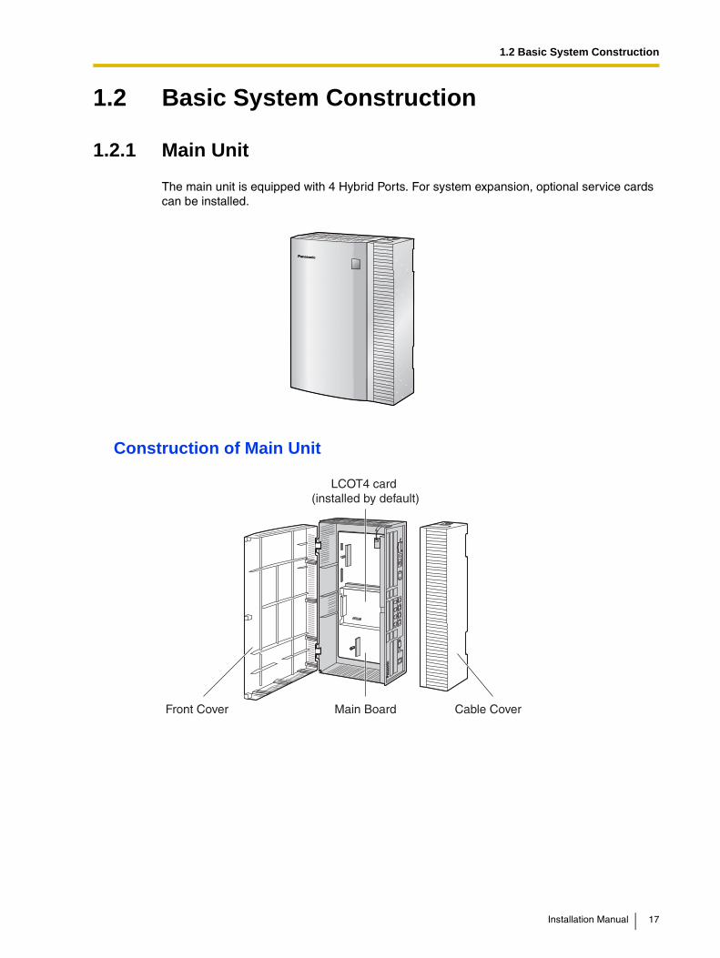
The main unit is equipped with 4 Hybrid Ports. For system expansion, optional service cards can be installed.
Construction of Main Unit
Main Board
LCOT4 card (installed by default)
Front Cover Cable Cover
Installation Manual 17

1.2 Basic System Construction
1.2.2 System Connection Diagram
Doorphone & Door Opener
BGM/Music On Hold (MOH)
Pager/Speaker
Voice Processing System
Remote PC
PC
Printer
Telephone Company(Analog CO Lines)
Advanced Hybrid & Wireless PBX
CSPS
Wireless Phone
Fax Machine
Amplifier
SLT
DSS ConsoleAPT
18 Installation Manual

1.2 Basic System Construction
*1 One LCOT4 card is installed by default.*2 The PBX has 4 Hybrid Ports pre-installed.
Doorphone & Door Opener
Station MessageDetail Recording (SMDR)
PC
LCOT4*1
(KX-TAW84880)
PLC8(KX-TAW84876)
PLC4(KX-TAW84875)
DPH4(KX-TAW84861)
SLC8(KX-TAW84874)
HLC4(KX-TAW84870)
ECHO8(KX-TAW84866)
MSG2(KX-TAW84891)
TelephoneCompany
SLT Wireless Phone Fax Machine
DSS ConsoleAPT
Radio
Amplifier Pager/Speaker
CID4(KX-TAW84893)
EXT-CID(KX-TAW84868)
SLT Wireless Phone Fax Machine
APT DSS Console
VoiceProcessingSystem
CS PS
AnalogAnalogCO LineCO LineAnalogCO Line
Advanced Hybrid & Wireless PBX
4 Hybrid Ports*2
Main Board
RMT(KX-TAW84896)
AC Cord & AC Adaptor
VoiceProcessingSystem
SLT Wireless Phone Fax Machine
APT DSS Console
VoiceProcessingSystem
CS PS
Installation Manual 19
1.3 Options
1.3 Options
1.3.1 Options
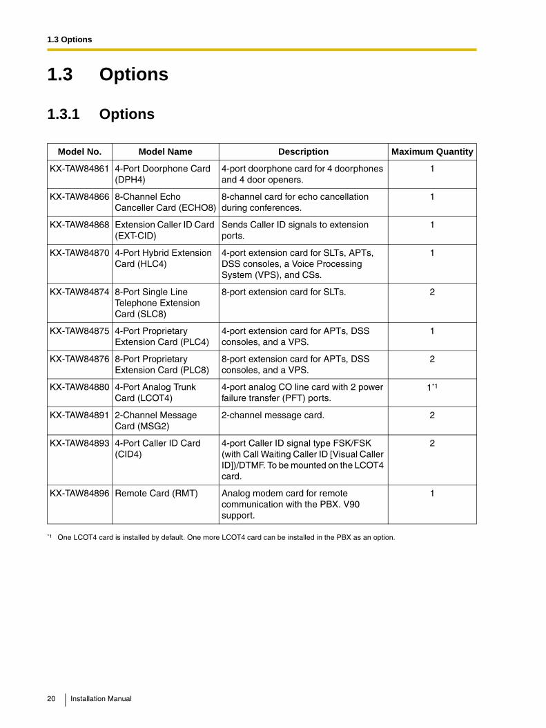
Model No. Model Name Description Maximum Quantity
KX-TAW84861 4-Port Doorphone Card (DPH4)
4-port doorphone card for 4 doorphones and 4 door openers.
1
KX-TAW84866 8-Channel Echo Canceller Card (ECHO8)
8-channel card for echo cancellation during conferences.
1
KX-TAW84868 Extension Caller ID Card (EXT-CID)
Sends Caller ID signals to extension ports.
1
KX-TAW84870 4-Port Hybrid Extension Card (HLC4)
4-port extension card for SLTs, APTs, DSS consoles, a Voice Processing System (VPS), and CSs.
1
KX-TAW84874 8-Port Single Line Telephone Extension Card (SLC8)
8-port extension card for SLTs. 2
KX-TAW84875 4-Port Proprietary Extension Card (PLC4)
4-port extension card for APTs, DSS consoles, and a VPS.
1
KX-TAW84876 8-Port Proprietary Extension Card (PLC8)
8-port extension card for APTs, DSS consoles, and a VPS.
2
KX-TAW84880 4-Port Analog Trunk Card (LCOT4)
4-port analog CO line card with 2 power failure transfer (PFT) ports.
1*1
*1 One LCOT4 card is installed by default. One more LCOT4 card can be installed in the PBX as an option.
KX-TAW84891 2-Channel Message Card (MSG2)
2-channel message card. 2
KX-TAW84893 4-Port Caller ID Card (CID4)
4-port Caller ID signal type FSK/FSK (with Call Waiting Caller ID [Visual Caller ID])/DTMF. To be mounted on the LCOT4 card.
2
KX-TAW84896 Remote Card (RMT) Analog modem card for remote communication with the PBX. V90 support.
1
20 Installation Manual

1.4 Specifications
1.4 Specifications
1.4.1 General Description
Switching Non Blocking
AC Adaptor AC Input 100 V AC to 240 V AC, 1.5 A, 50 Hz/60 Hz
DC Output 40 V, 1.38 A (55.2 W)
DC Input 40 V, 1.38 A (55.2 W)
Maximum Power Failure Tolerance
300 ms
Memory Backup Duration 7 years
Dialing CO Line Dial Pulse (DP) 10 pps, 20 ppsTone (DTMF) Dialing
Extension Dial Pulse (DP) 10 pps, 20 ppsTone (DTMF) Dialing
Connectors CO Line RJ11 (2 wire) × each CO ports
Extension RJ11 (4 wire) × each extension ports
Paging Output 1 conductor jack
External MOH (Music on Hold) Output
1 conductor jack
Mode Conversion DP-DTMF, DTMF-DP
Ring Frequency 20 Hz/25 Hz (selectable)
Central Office Loop Limit 1600 maximum
Operating Environment
Temperature 0 °C to 40 °C (32 °F to 104 °F)
Humidity 10 % to 90 % (non condensing)
Conference Call CO Line From 10 × 3-party conference call to 4 × 8-party conference call
Music on Hold 1 port (Level Control: -11 dB to +11 dB in 1 dB steps)Selectable Tone/External Music Source port
Paging Internal Level Control: -15 dB to +6 dB in 3 dB steps
External 1 port (Volume Control: -15 dB to +15 dB in 1 dB steps)
Serial Interface Port
RS-232C 1 (maximum 115.2 kbps)
USB 1
Extension Connection Cable SLT 1-pair wire (T, R)
APT 2-pair wire (T, R, D1, D2)
DSS Console 1-pair wire (D1, D2)
Installation Manual 21
1.4 Specifications
Dimension 275 mm (W) × 376 mm (H) × 117 mm (D)(10-4/5 in × 14-4/5 in × 4-3/5 in)
Weight (when fully mounted) Under 3.5 kg (7.72 lb)
22 Installation Manual

1.4 Specifications
1.4.2 Characteristics
Terminal Equipment Loop Limit • APT: 40
• SLT: 600 including set
• Doorphone: 20
• CS: 65
Minimum Leakage Resistance 15 000 minimum
Maximum Number of Extension Instruments per Line
1 for APT or SLT
2 by Parallel connection of an APT and an SLT
Ring Voltage 75 Vrms at 20 Hz/25 Hz depending on the Ringing Load
Central Office Loop Limit 1600 maximum
Hookswitch Flash Timing Range
24 ms to 2032 ms
Door Opener Current Limit 24 V DC/30 V AC, 1 A maximum
Paging Terminal Impedance 600
MOH Terminal Impedance 10 000
Installation Manual 23

1.4 Specifications
1.4.3 System Capacity
Maximum CO Line and Extension CardsThe following number of CO line and extension cards can be installed in the PBX for expansion.
Notes• For each card, the maximum number that can be installed in the PBX is listed in "1.3.1
Options".
• Any card that exceeds the capacity of the PBX will be ignored.
• When the PBX starts up with an invalid configuration, some cards will be ignored.
Maximum Terminal EquipmentThe PBX supports a maximum of 28 items of terminal equipment, including 4 SLTs that are connected by the parallel connection to APTs using the Hybrid Ports.
NoticeDevices connected to the PBX that exceed the system capacity will not function.
Card Type Maximum Number
CO Line Card 2
Extension Card 3
Terminal Equipment Type Maximum Number
SLT 24
APT 24
CS 4
PS 28
VPS 1 System*1
*1 A maximum of 4 ports (8 channels) of a single VPS can be connected to the PBX.
Doorphone 4
Door Opener 4
24 Installation Manual

Section 2
Installation
This section describes the procedures to install the PBX. Detailed instructions for planning the installation site, installing the optional service cards, and cabling of peripheral equipment are provided. Further information on system expansion and peripheral equipment installation is included.
Installation Manual 25
2.1 Before Installation
2.1 Before Installation
2.1.1 Before Installation
Please read the following notes concerning installation and connection before installing the PBX. Be sure to comply with applicable local regulations (e.g., law, guidelines).
Safety Installation InstructionsWhen installing telephone wiring, basic safety precautions should always be followed to reduce the risk of fire, electric shock and injury to persons, including the following:
1. Never install telephone wiring during a lightning storm.
2. Never install telephone jacks in wet locations unless the jack is specifically designed for wet locations.
3. Never touch uninsulated telephone wires or terminals unless the telephone line has been disconnected at the network interface.
4. Use caution when installing or modifying telephone lines.
5. Anti-static precautions should be taken during installation.
Installation PrecautionsThis set is made for wall mounting. Avoid installing in the following places. (Doing so may result in malfunction, noise, or discoloration.)
1. In direct sunlight and hot, cold, or humid places.Temperature range: 0 °C to 40 °C (32 °F to 104 °F)
2. Sulphuric gases produced in areas where there are thermal springs, etc. may damage the equipment or contacts.
3. Places in which shocks or vibrations are frequent or strong.
4. Dusty places, or places where water or oil may come into contact with the unit.
5. Near high-frequency generating devices such as sewing machines or electric welders.
6. On or near computers, telexes, or other office equipment, as well as microwave ovens or air conditioners. (It is preferable not to install in the same room with the above equipment.)
7. Closer than 1.8 m (6 ft) to radios and televisions (both the PBX and APTs).
8. Do not obstruct the area around the PBX (for reasons of maintenance and inspection—be especially careful to allow at least 20 cm (8 in) above and 10 cm (4 in) at the sides of the PBX for cooling).
9. Do not block the openings at top of the PBX.
10. Do not stack up the optional service cards. To avoid damage to the optional service cards, always use the extension bolts.
Wiring PrecautionsBe sure to follow these instructions when wiring.
1. Do not wire the telephone cable in parallel with an AC power source, computer, telex, etc. If the cables are run near those wires, shield the cables with metal tubing or use shielded cables and ground the shields.
2. If cables are run on the floor, use protectors to prevent the wires from being stepped on. Avoid wiring under carpets.
26 Installation Manual

2.1 Before Installation
3. Avoid using the same power supply outlet for computers, telexes, and other office equipment. Otherwise, the PBX operation may be interrupted by the inducted noise from such equipment.
4. Please use 1-pair telephone wire for extension connection of (telephone) equipment such as standard telephones, data terminals, answering machines, computers, Voice Processing Systems, etc., except APTs (e.g., KX-T7730).
5. The power switch of the PBX must be off during wiring. After the wiring is completed, turn the power switch on.
6. Mis-wiring may cause the PBX to operate improperly.
7. If an extension does not operate properly, disconnect the telephone from the extension line and then connect again, or turn the power to the PBX off and on again.
8. The PBX is equipped with a 3-wire grounding type plug. This is a safety feature. If you are unable to insert the plug into the outlet, contact your electrician to replace your obsolete outlet. Do not defeat the purpose of the grounding-type plug.
9. Use twisted pair cable for CO line connection.
10. CO lines should be installed with lightning protectors. For details, refer to "2.2.10 Lightning Protector Installation".
11. To assure good quality telephone connection, it is recommended new and modifications to existing installation of customer premise wiring shall use solid twisted pair copper conductors with minimum 24 gauge that comply with the electrical specifications for Category 3 wiring as detailed in ANSI/EIA/TIA-570A Building Wiring Standards.
Installation Manual 27
2.2 Installation of the PBX
2.2 Installation of the PBX
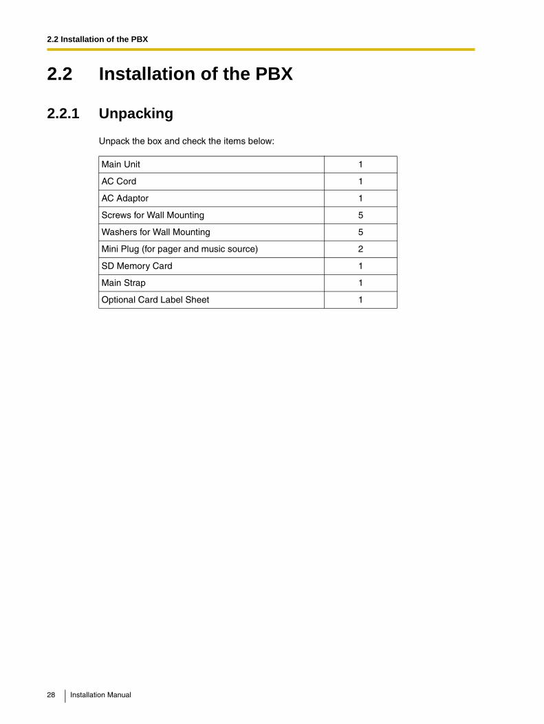
2.2.1 Unpacking
Unpack the box and check the items below:
Main Unit 1
AC Cord 1
AC Adaptor 1
Screws for Wall Mounting 5
Washers for Wall Mounting 5
Mini Plug (for pager and music source) 2
SD Memory Card 1
Main Strap 1
Optional Card Label Sheet 1
28 Installation Manual

2.2 Installation of the PBX
2.2.2 Names and Locations
SD Memory Card Slot CoverReset Button
MOH portPager port
Hybrid Ports
RS-232C port
USB port
System Initialize Switch
DC IN 1
Ground Terminal
Power Switch
Installation Manual 29

2.2 Installation of the PBX
2.2.3 Opening/Closing the Covers
Opening the Covers1. Pull the slide button to the right and, holding it, slide the cable cover upwards. Then turn
the cable cover slightly to remove it.
2. Remove the three screws.
3. Holding the protrusions on both sides of the front cover, swing the cover open.
1Slide Button
Cable Cover
Screw
30 Installation Manual

2.2 Installation of the PBX
Removing/Attaching the Front CoverIf you prefer, you can remove the front cover.
Removing the Front Cover
Holding the front cover open at about a 45° angle, remove the front cover by pushing it in the direction of the arrow as shown below.
Attaching the Front Cover
Fit the front cover to the main unit as shown below, and then close the front cover.
Installation Manual 31

2.2 Installation of the PBX
Closing the Covers1. Close the front cover, then tighten the three screws.
2. Attach the rear hooks on the cable cover to the main unit, then swing the cable cover closed so that the front hooks fit in place.
3. Slide the cable cover down until it locks.
Screw
Cable Cover
32 Installation Manual

2.2 Installation of the PBX
2.2.4 Installation of the SD Memory Card
CAUTION• Use only the SD Memory Card included with the PBX.
• The SD Memory Card contains software for all the processes of the PBX and all the customer data. The SD Memory Card must be inserted before start up.
• Do not remove the SD Memory Card during the operation of the PBX. Removing the SD Memory Card during operation may cause damage to the SD Memory Card, or result in loss of data.
Note
If you need to remove the SD Memory Card:
LED Indications
Indication Color Description
SD ACCESS Green SD memory card status
• ON: Accessing
SD Memory CardSlot Cover
SD MemoryCard
LED
Installation Manual 33
2.2 Installation of the PBX
2.2.5 Frame Ground Connection
IMPORTANTConnect the frame of the PBX to earth.
• Be sure to comply with applicable local regulations (e.g., law, guidelines).
• Proper grounding (connection to earth) is very important to protect the PBX from the bad effects of external noise or to reduce the risk to the user of electrocution in the case of lightning strike.
• The ground wire of the AC cable has an effect against the external noise and lightning strikes, but it may not be enough to protect the PBX. A permanent connection between earth and the ground terminal of the PBX must be made.
In most of the continental United States, the ground provided by the "Third wire ground" at the commercial power outlet will be satisfactory. However, in a small percentage of cases this ground may be installed incorrectly. Therefore, the following test procedure should be performed.
Test Procedure1. Obtain a suitable voltmeter and set it for a possible reading of up to 250 V AC.
2. Connect the meter probes between the 2 main AC voltage points on the wall outlet. The reading obtained should be 108 V AC to 132 V AC.
3. Move one of the meter probes to the 3rd prong terminal (GND).Either the same reading or a reading of 0 volt should be obtained.
4. If a reading of 0 volt at one terminal and a reading of 108 V AC to 132 V AC at the other terminal is not obtained, the outlet is not properly grounded.This condition should be corrected by a qualified electrician (per article 250 of the National Electrical Code).
5. If a reading of 0 volt at one terminal and a reading of 108 V AC to 132 V AC at the other terminal is obtained, then set the meter to the "OHMS/RX1" scale, place one probe at the GND Terminal and the other probe at the terminal which gave a reading of 0 volt.A reading of less than 1 ohm should be obtained. If the reading is not obtained, the outlet is not adequately grounded. See qualified electrician.
1. Loosen the screw.
2. Insert a grounding wire (user-supplied)*.
3. Tighten the screw.
4. Connect the grounding wire to earth.
* For grounding wire, green-and-yellow insulation is required, and the cross-sectional area of the conductor must be more than 0.75 mm2 or 18 AWG.
Screw
Groundingwire
To ground
34 Installation Manual
2.2 Installation of the PBX
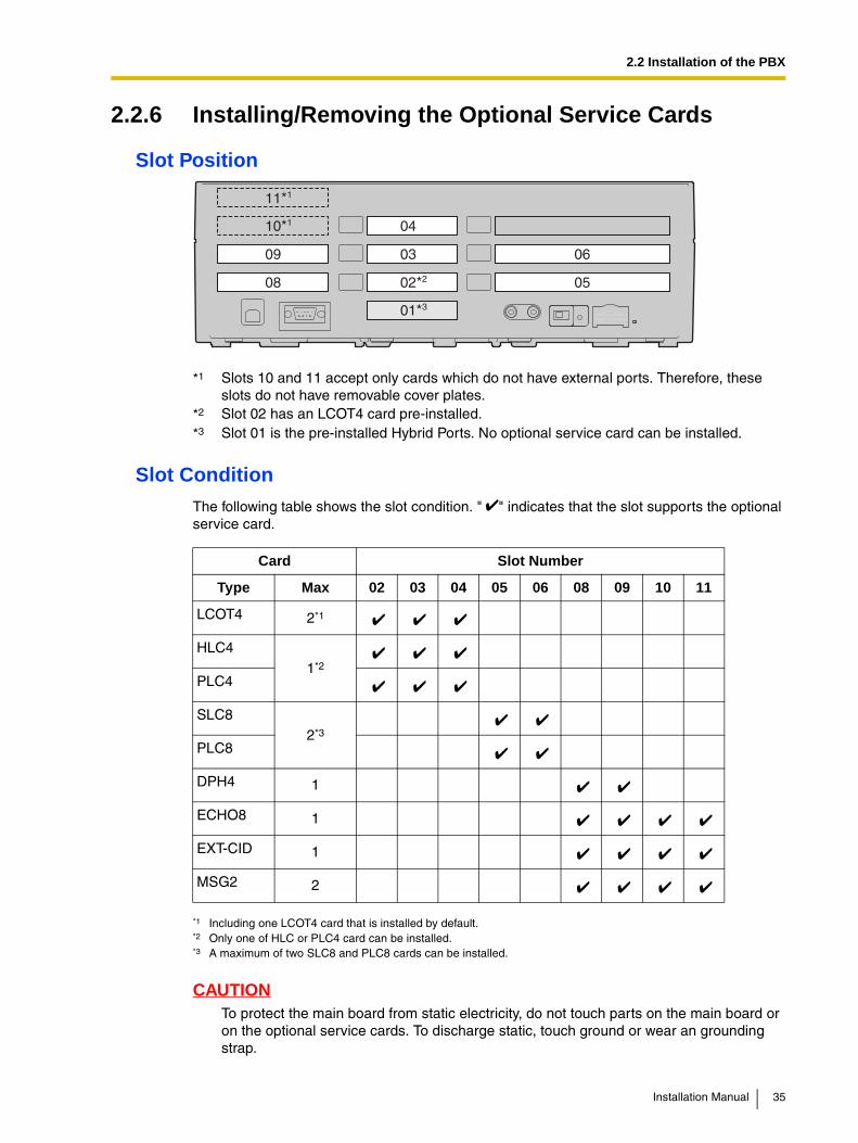
2.2.6 Installing/Removing the Optional Service Cards
Slot Position
Slot Condition
The following table shows the slot condition. " " indicates that the slot supports the optional service card.
CAUTIONTo protect the main board from static electricity, do not touch parts on the main board or on the optional service cards. To discharge static, touch ground or wear an grounding strap.
*1 Slots 10 and 11 accept only cards which do not have external ports. Therefore, these slots do not have removable cover plates.
*2 Slot 02 has an LCOT4 card pre-installed.*3 Slot 01 is the pre-installed Hybrid Ports. No optional service card can be installed.
Card Slot Number
Type Max 02 03 04 05 06 08 09 10 11
LCOT4 2*1
*1 Including one LCOT4 card that is installed by default.
HLC41*2
*2 Only one of HLC or PLC4 card can be installed.
PLC4
SLC82*3
*3 A maximum of two SLC8 and PLC8 cards can be installed.
PLC8
DPH4 1
ECHO8 1
EXT-CID 1
MSG2 2
02*2
03
04
05
06
08
09
10*1
11*1
01*3
Installation Manual 35

2.2 Installation of the PBX
Note
When installing or removing the optional service cards, the DC power supply must be stopped.
Installing Optional Service Cards1. Before installing the optional service cards, cut and remove the appropriate dummy cover
plates from the main unit.
CAUTIONFor safety reasons, smooth the cut edges after removing the dummy cover plates.
2. Position the card in the open slot, making sure that the tabs on the both sides of the card fit into place. Then, holding the card firmly in place, lower the rear end so that the hole of the card fits over the extension bolt.
Dummy Cover Plate
1
2
Extension Bolt
Optional Service Card
36 Installation Manual
2.2 Installation of the PBX
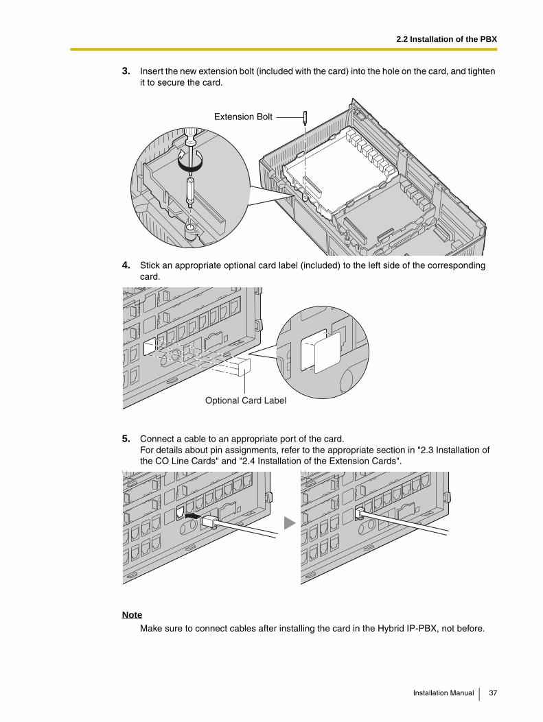
3. Insert the new extension bolt (included with the card) into the hole on the card, and tighten it to secure the card.
4. Stick an appropriate optional card label (included) to the left side of the corresponding card.
5. Connect a cable to an appropriate port of the card.For details about pin assignments, refer to the appropriate section in "2.3 Installation of the CO Line Cards" and "2.4 Installation of the Extension Cards".
NoteMake sure to connect cables after installing the card in the Hybrid IP-PBX, not before.
Extension Bolt
Optional Card Label
Installation Manual 37

2.2 Installation of the PBX
6. Repeat the procedure for other cards.
• When installing a card in Slot 11, tighten the card using the screw included with the card, instead of the extension bolt.
Screw
38 Installation Manual

2.2 Installation of the PBX
Handling of the Cables1. Attach the strap included with the card to one of the connected cables.
2. Bind all the connected cables together using the strap.
3. Repeat the procedure for other cards.
Strap
Installation Manual 39

2.2 Installation of the PBX
4. Attach the main strap (included with the PBX) to any of the 5 rails depending on your preference.
1
2
Main Strap
40 Installation Manual

2.2 Installation of the PBX
5. Bind all the connected cables together using the main strap, and then close the cable cover. For how to close the cable cover, refer to "2.2.3 Opening/Closing the Covers".
Notes
• For safety reasons, do not stretch, bend, or pinch the cables.
• If you prefer, you can cut the other side of the cable cover and run the cables through that opening. For safety reasons, smooth the cut edges.
Cable Cover
Main Strap
Installation Manual 41

2.2 Installation of the PBX
Removing the Optional Service Cards1. Loosen the extension bolt.
2. Holding the protrusions of the card, pull the card in the direction of the arrows.
42 Installation Manual

2.2 Installation of the PBX
2.2.7 Types of Connectors
Connector Type Pin Number Used for
(Twisted pair cable)
• DPH4 (TAW84861)
• HLC4 (TAW84871)
• SLC8 (TAW84874)
• PLC4 (TAW84875)
• PLC8 (TAW84876)
• LCOT4 (TAW84880)
• Hybrid Ports (Main Board)
• DPH4 (KX-TAW84861)
• Main Board
• Main Board
• Main Board (Pager port, MOH port)
RJ11
4 1
10-pinTerminal Block
8-pinTerminal Block 81
101
RS-232C
6 9
1 5
USB2
3
1
4
Mini Plug+
-
Installation Manual 43

2.2 Installation of the PBX
2.2.8 Wall Mounting (KX-TAW848)
Mounting on Wooden Wall1. Place the reference for wall mounting on the wall to mark the three screw positions.
2. Install the screws and washers (included) in the wall.
Notes
• Make sure that the screw heads are at the same distance from the wall.
• Install the screws perpendicular to the wall.
3. Hook the main unit on the screw heads.
Notes• Do not block the openings of the cabinet. Allow space of at least 20 cm (8 in) above
and 10 cm (4 in) at the sides of the cabinet.
• Make sure that the wall behind the cabinet is flat and free of obstacles, so that the openings on the back of the cabinet will not be blocked.
• Be careful not to drop the cabinet.
250 mm(9.8 in)
130 mm (5.1 in)
Washer
Drive the screwto this position.
44 Installation Manual
2.2 Installation of the PBX
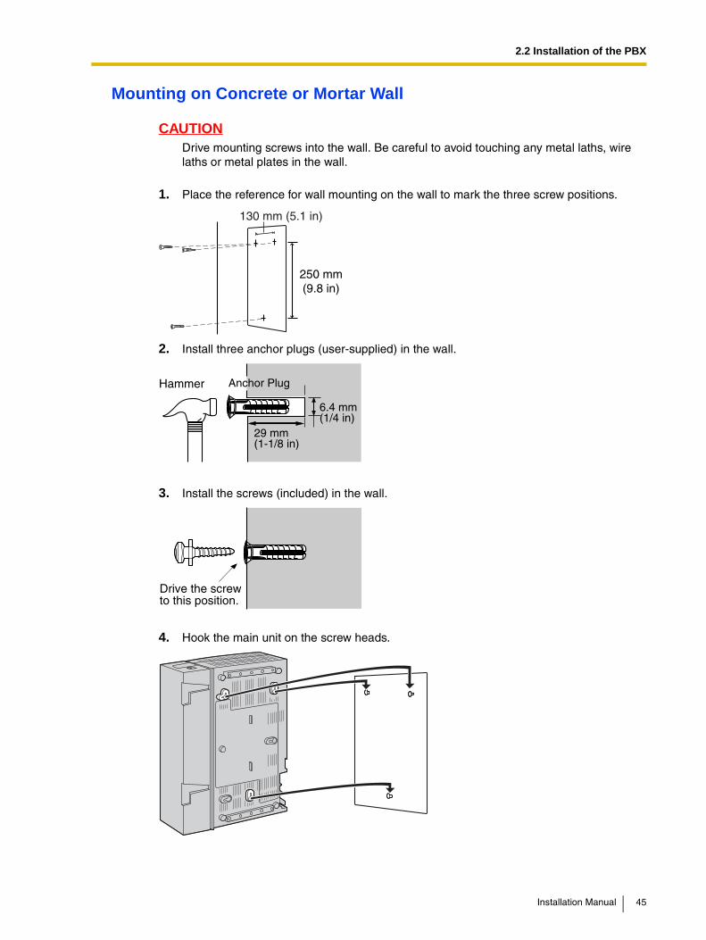
Mounting on Concrete or Mortar Wall
CAUTIONDrive mounting screws into the wall. Be careful to avoid touching any metal laths, wire laths or metal plates in the wall.
1. Place the reference for wall mounting on the wall to mark the three screw positions.
2. Install three anchor plugs (user-supplied) in the wall.
3. Install the screws (included) in the wall.
4. Hook the main unit on the screw heads.
250 mm(9.8 in)
130 mm (5.1 in)
Hammer
29 mm(1-1/8 in)
Anchor Plug
6.4 mm(1/4 in)
Drive the screwto this position.
Installation Manual 45

2.2 Installation of the PBX
Notes
• Do not block the openings of the cabinet. Allow space of at least 20 cm (8 in) above and 10 cm (4 in) at the sides of the cabinet.
• Make sure that the wall behind the cabinet is flat and free of obstacles, so that the openings on the back of the cabinet will not be blocked.
• Be careful not to drop the cabinet.
46 Installation Manual

2.2 Installation of the PBX
2.2.9 Wall Mounting (AC Adaptor)
Mounting on Wooden Wall1. Place the reference for wall mounting (on the following page) on the wall to mark the two
screw positions.
2. Install the screws and washers (included) in the wall.
Notes• Make sure that the screw heads are at the same distance from the wall.
• Install the screws perpendicular to the wall.
3. Hook the AC adaptor on the screw heads.
Note
Be careful not to drop the AC adaptor.
110 mm(4.4 in)
Washer
Drive the screwto this position.
Installation Manual 47

2.2 Installation of the PBX
Mounting on Concrete or Mortar Wall
CAUTIONDrive mounting screws into the wall. Be careful to avoid touching any metal laths, wire laths or metal plates in the wall.
1. Place the reference for wall mounting (on the following page) on the wall to mark the two screw positions.
2. Install two anchor plugs (user-supplied) in the wall.
3. Install the screws (included) in the wall.
4. Hook the AC adaptor on the screw heads.
Note
Be careful not to drop the AC adaptor.
110 mm(4.4 in)
Hammer
29 mm(1-1/8 in)
Anchor Plug
6.4 mm(1/4 in)
Drive the screwto this position.
48 Installation Manual

2.2 Installation of the PBX
Reference for Wall MountingPlease copy this page and use as a reference for wall mounting.
NoteWhen you print out this page, the distance on the paper output may deviate slightly from the measurement indicated above.
Install a screw here.
Install a screw here.
110 mm(4-5/16 in)
Installation Manual 49

2.2 Installation of the PBX
2.2.10 Lightning Protector Installation
OverviewA lightning protector is a device that must be installed on a CO line to prevent a dangerous surge from entering the building and damaging equipment.
A dangerous surge can occur if a telephone line comes in contact with a power line. Trouble due to lightning surges has been showing a steady increase with the development of electronic equipment.
In many countries, there are regulations requiring the installation of lightning protection. A lightning strike to a telephone cable which is 10 m (33 ft) above ground can be as high as 200 000 V.
The PBX must be installed with lightning protectors. In addition, grounding (connection to earth) is very important for the protection of the user.
Be sure to comply with applicable local regulations (e.g., law, guidelines).
Recommended Lightning Protectors• KX-A207
• TELESPIKE BLOK MODEL TSB (TRIPPE MFG. CO.)
• SPIKE BLOK MODEL SK6-0 (TRIPPE MFG. CO.)
• Krone 237A strips fitted with 14A/1 surge arrestors
• Super MAX™ (PANAMAX)
• MP1 (ITW LINK)
Installation
CS
Extn.
Extn. Extn. Extn.
SLT APT
CO Line CO Line CO Line
Extn.: Extension line
LightningProtectors
TerminalBoard
PBX
FrameGround
Earth
50 Installation Manual

2.2 Installation of the PBX
Outside Installation
If you install an extension outside of the building, the following precautions are recommended:
a. Install the extension wire underground.
b. Use a conduit to protect the wire.
NoteThe lightning protector for an extension and CS may be different from that for CO lines.
Installation of an Earth Rod
CSSLT APT
(Main Building)
CO Line
CO Line
Extn.
Extn.
Extn.: Extension Line
Earth
(Another Building)
Extn. Extn.
Lightning Protectors
TerminalBoard Lightning
Protector
SLT
APTHybridIP-PBX CS
CO Line
HybridIP-PBX
GroundingWire
Earth Rod(Underground)
Lightning Protector
Installation Manual 51

2.2 Installation of the PBX
1. Installation location of the earth rod.....Near the protector
2. Check obstructions.....None
3. Composition of the earth rod.....Metal
4. Depth of the earth rod.....More than 50 cm (20 in)
5. Size of the grounding wire.....Thickness is more than 16 AWG
Notes
• The above figures are recommendations only.
• The length of earth rod and the required depth depend on the composition of the soil.
52 Installation Manual

2.3 Installation of the CO Line Cards
2.3 Installation of the CO Line Cards
2.3.1 LCOT4 Card
Function4-port analog CO line card with 2 power failure transfer (PFT) ports. One CID4 card can be mounted on the LCOT4 card (refer to "2.3.2 CID4 Card").
Accessory and User-supplied ItemsAccessory (included): Extension Bolt × 1, Strap × 1
User-supplied (not included): RJ11 connector
Notes
• To confirm the CO line connection, refer to "Confirming the CO Line Connection" in "2.11.1 Starting the PBX".
• For details about power failure transfer, refer to "2.10.1 Power Failure Connections".
Pin Assignments
RJ11 Connector
Signal Name Function
R Ring
T Tip
– Reserved
To CO line
RJ11
PFT Port 1
PFT Port 2
4 1
T R
Installation Manual 53
2.3 Installation of the CO Line Cards
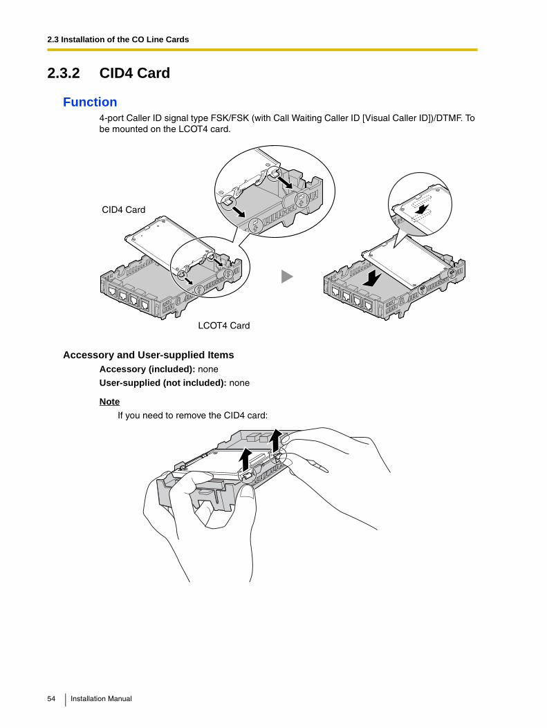
2.3.2 CID4 Card
Function4-port Caller ID signal type FSK/FSK (with Call Waiting Caller ID [Visual Caller ID])/DTMF. To be mounted on the LCOT4 card.
Accessory and User-supplied ItemsAccessory (included): none
User-supplied (not included): none
Note
If you need to remove the CID4 card:
CID4 Card
LCOT4 Card
54 Installation Manual

2.4 Installation of the Extension Cards
2.4 Installation of the Extension Cards
2.4.1 HLC4 Card
Function4-port extension card for SLTs, APTs, DSS consoles, a Voice Processing System (VPS), and CSs.
Accessory and User-supplied ItemsAccessory (included): Extension Bolt × 1, Strap × 1
User-supplied (not included): RJ11 connector
Note
For details about connecting the CS, refer to "2.7.7 Connecting a Cell Station to the PBX".
Pin Assignments
RJ11 Connector
Signal Name Function
D1 Data port (High Volt)
T Tip
R Ring
D2 Data port (Low Volt)
To extension
RJ11
4 1
R T
D2 D1
Installation Manual 55

2.4 Installation of the Extension Cards
2.4.2 PLC4 Card
Function4-port extension card for APTs, DSS consoles, and a VPS.
Accessory and User-supplied ItemsAccessory (included): Extension Bolt × 1, Strap × 1
User-supplied (not included): RJ11 connector
Pin Assignments
RJ11 Connector
Signal Name Function
D1 Data port (High Volt)
T Tip
R Ring
D2 Data port (Low Volt)
To extension
RJ11
4 1
R T
D2 D1
56 Installation Manual
2.4 Installation of the Extension Cards
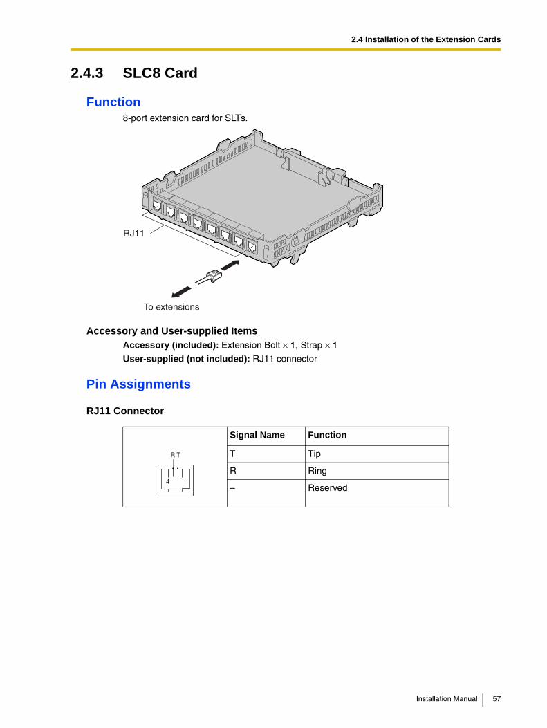
2.4.3 SLC8 Card
Function8-port extension card for SLTs.
Accessory and User-supplied ItemsAccessory (included): Extension Bolt × 1, Strap × 1
User-supplied (not included): RJ11 connector
Pin Assignments
RJ11 Connector
Signal Name Function
T Tip
R Ring
– Reserved
To extensions
RJ11
4 1
R T
Installation Manual 57

2.4 Installation of the Extension Cards
2.4.4 PLC8 Card
Function8-port extension card for APTs, DSS consoles, and a VPS.
Accessory and User-supplied ItemsAccessory (included): Extension Bolt × 1, Strap × 1
User-supplied (not included): RJ11 connector
Pin Assignments
RJ11 Connector
Signal Name Function
D1 Data port (High Volt)
T Tip
R Ring
D2 Data port (Low Volt)
To extensions
RJ11
4 1
R T
D2 D1
58 Installation Manual

2.5 Installation of the Other Cards
2.5 Installation of the Other Cards
2.5.1 DPH4 Card
Function4-port doorphone card for 4 doorphones and 4 door openers.
Accessory and User-supplied Items
User-supplied (not included): Copper wire
Note
For details about connection to doorphones and door openers, refer to "2.8.1 Connection of Doorphones and Door Openers".
Pin Assignments
RJ11 Connector
Accessory (included): Extension Bolt × 1, Strap × 1, 8-pin terminal block × 1, 10-pin terminal block × 1, Telephone Line Cord × 2, Terminal Box × 2
Signal Name Function
DP2 Doorphone 2 transmit
DP1 Doorphone 1 transmit
com1 Doorphone 1 receive
com2 Doorphone 2 receive
DP4 Doorphone 4 transmit
DP3 Doorphone 3 transmit
com3 Doorphone 3 receive
com4 Doorphone 4 receive
To door openers
Telephone Line Cord
8-pin
10-pin
RJ11
To doorphones
DP2DP1com1
com2
DP4DP3com3
com4
5 81 4
Installation Manual 59
2.5 Installation of the Other Cards
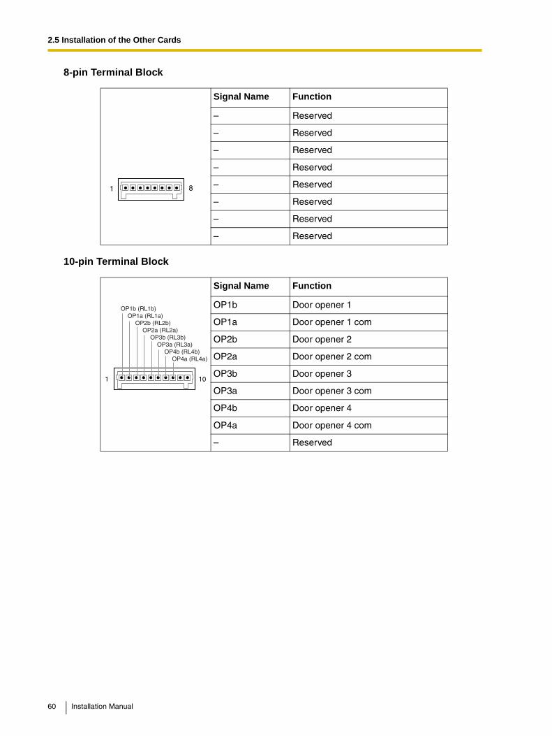
8-pin Terminal Block
10-pin Terminal Block
Signal Name Function
– Reserved
– Reserved
– Reserved
– Reserved
– Reserved
– Reserved
– Reserved
– Reserved
Signal Name Function
OP1b Door opener 1
OP1a Door opener 1 com
OP2b Door opener 2
OP2a Door opener 2 com
OP3b Door opener 3
OP3a Door opener 3 com
OP4b Door opener 4
OP4a Door opener 4 com
– Reserved
1 8
1 10
OP1b (RL1b)OP1a (RL1a)
OP2b (RL2b)OP2a (RL2a)
OP3b (RL3b)OP3a (RL3a)
OP4b (RL4b)OP4a (RL4a)
60 Installation Manual

2.5 Installation of the Other Cards
2.5.2 ECHO8 Card
Function8-channel card for echo cancellation during conferences.
Accessory and User-supplied ItemsAccessory (included): Extension Bolt × 1, Screw × 1
User-supplied (not included): none
Note
To establish a conference call involving 6 to 8 parties, install an ECHO8 card and enable the echo cancellation for conference using the KX-TAW848 Maintenance Console (refer to "3.3.3 PBX Configuration").
Installation Manual 61

2.5 Installation of the Other Cards
2.5.3 MSG2 Card
Function2-channel message card.
Accessory and User-supplied ItemsAccessory (included): Extension Bolt × 1, Screw × 1
User-supplied (not included): none
62 Installation Manual
2.5 Installation of the Other Cards
2.5.4 EXT-CID Card
FunctionSends Caller ID signals to extension ports.
Accessory and User-supplied ItemsAccessory (included): Extension Bolt × 1, Screw × 1
User-supplied (not included): none
Installation Manual 63

2.5 Installation of the Other Cards
2.5.5 RMT Card
FunctionAnalog modem card for remote communication with the PBX. V90 support.
Accessory and User-supplied ItemsAccessory (included): none
User-supplied (not included): none
CAUTIONMake sure to insert the RMT card between the guide rails until it locks into the RMT slot.
Removing the RMT CardPull open the guide rails using a flathead screwdriver and, while holding them open, remove the RMT card.
RMT Slot
RMT Card
64 Installation Manual
2.6 Connection of Extensions
2.6 Connection of Extensions
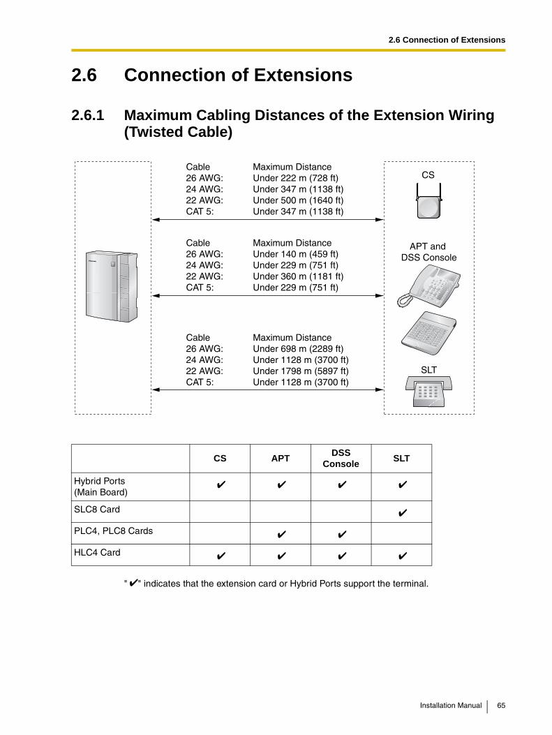
2.6.1 Maximum Cabling Distances of the Extension Wiring (Twisted Cable)
" " indicates that the extension card or Hybrid Ports support the terminal.
CS APTDSS
ConsoleSLT
Hybrid Ports(Main Board)
SLC8 Card
PLC4, PLC8 Cards
HLC4 Card
Cable Maximum Distance26 AWG: Under 222 m (728 ft)24 AWG: Under 347 m (1138 ft)22 AWG: Under 500 m (1640 ft)CAT 5: Under 347 m (1138 ft)
Cable Maximum Distance26 AWG: Under 140 m (459 ft)24 AWG: Under 229 m (751 ft)22 AWG: Under 360 m (1181 ft)CAT 5: Under 229 m (751 ft)
Cable Maximum Distance26 AWG: Under 698 m (2289 ft)24 AWG: Under 1128 m (3700 ft)22 AWG: Under 1798 m (5897 ft)CAT 5: Under 1128 m (3700 ft)
APT and DSS Console
SLT
CS
Installation Manual 65

2.6 Connection of Extensions
2.6.2 Parallel Connection of the Extensions
Any SLT can be connected in parallel with an APT as follows:
NoteIn addition to an SLT, an answering machine, a fax machine or a modem (PC) can be connected in parallel with APTs.
To a Hybrid Port
4-conductor wiring cordConnect pins "T", "R", "D1",and "D2".
2-conductor wiring cordConnect pins "T" and "R".
SLTAPT
ModularT-Adaptor
66 Installation Manual

2.7 Connection of 2.4 GHz Portable Stations
2.7 Connection of 2.4 GHz Portable Stations
2.7.1 Overview
The following equipment is required to connect the wireless system:
CS: Cell Station (KX-T0141)This unit determines the area covered by the wireless system. Up to 2 calls can be made at the same time through each CS.
PS: 2.4 GHz Portable Station (KX-TD7680/KX-TD7690)The KX-TAW848 can support up to 28 PSs. For more details about the PS, refer to the PS Operating Instructions.
CAUTION• The CS should be kept free of dust, moisture, high temperature (more than 40 °C [104
°F]), low temperature (less than 0 °C [32 °F]), vibration, and should not be exposed to direct sunlight.
• The CS should not be placed outdoors (use indoors).
• The CS should not be placed near high voltage equipment.
• The CS should not be placed on a metal object.
• Systems using 2.4 GHz ISM (Industrial, Scientific and Medical) band may interfere with the wireless system. Examples of such systems are cordless telephones, wireless LAN, Home RF, microwave ovens and other ISM devices. These systems may cause minor noise.
• Keeping some distance between the equipment listed below may prevent interference. (The distance may vary depending on the environment.)
Equipment Distance
CS and office equipment such as a computer, telex, fax machine, etc.
More than 2 m (6.6 ft)
CS and PS More than 1 m (3.3 ft)
Each PS More than 0.5 m (1.6 ft)
PBX and CS More than 2 m (6.6 ft)
CS and CS More than 15 m (49 ft)
Please take into consideration the distance between the CSs when site planning. Please consult your dealer for details.However, the required distance between CSs may vary depending on the environment of the installation site and conditions in which the wireless system is used. Conduct the site survey to determine the appropriate distance.
Installation Manual 67

2.7 Connection of 2.4 GHz Portable Stations
2.7.2 Procedure Overview
When connecting the wireless system, use extreme care to conduct a site survey. Inadvertent site survey can result in poor service area, frequent noise, and disconnection of calls.
1. Investigate the installation siteRefer to "2.7.3 Site Planning".
a. Obtain the map of the CS installation site.
b. Consider the service area demanded by the user on the map.
c. Plan the locations of each CS, taking account of distance, building materials and etc.
2. Prepare the CS for site surveyRefer to "2.7.4 Before Site Survey".
a. Assign a CS number to each CS by setting the DIP switches on the back of the CS.
b. Supply electricity to each CS using an AC adaptor or a battery box.
c. Install each CS temporarily as planned.
Notes
• Install at least 2 m (6.6 ft) above the floor.
• Keep the antennas in the upright position.
3. Conduct the site surveyRefer to "2.7.5 Site Survey".
a. Test the radio signal strength using the PS.Confirm that the radio signal strength level is "12" near the CS.
Using the KX-TD7680
Using the KX-TD7690
b. By walking away from the CS with the PS, check the radio signal strength. The radio signal strength weakens as you walk away from the CS.
c. Map the CS coverage area at radio signal strength levels "3" and "8".
d. Make sure that adjacent CS coverage areas overlap where the radio signal strength level is "8" by at least 5 m (16 ft).
e. Make sure that the radio signal strength level is greater than "3" at any location within the service area demanded by the user.
Display example:
Press 1, 9, and POWERfor more than 2 seconds.
<< SEARCHING >>CS NO.1 LEVEL:12
SAVE:01234567891 to 9
CS No.1 9 0
Display example:
Press 1, 9, and POWERfor more than 2 seconds.
<< SEARCHING >>CS NO.1 LEVEL:12
SAVE:01234567891 to 9
CS No.1 99 0
68 Installation Manual

2.7 Connection of 2.4 GHz Portable Stations
4. Finish the site surveyRefer to "2.7.6 After Site Survey".
a. Return all DIP switches of each CS to the OFF position, and stop supplying power.
b. Turn off the PS.
5. Connect the CS and PS to the PBX and test the operationRefer to "2.7.7 Connecting a Cell Station to the PBX".
a. Connect the CSs to the PBX.
b. Register the PSs to the PBX.
c. Walk around the service area while having a conversation using a registered PS. If noise is frequent or conversations disconnect, relocate the CSs or install additional CS.
6. Mount the CS on the wallRefer to "2.7.8 Wall Mounting".
a. Assuming everything goes as planned, mount the CS on the wall.
Installation Manual 69

2.7 Connection of 2.4 GHz Portable Stations
2.7.3 Site Planning
Choosing the best site for the CS requires careful planning and testing of essential areas. The best location may not always be convenient for installation. Read the following information before installing the unit.
Understanding the Radio Waves
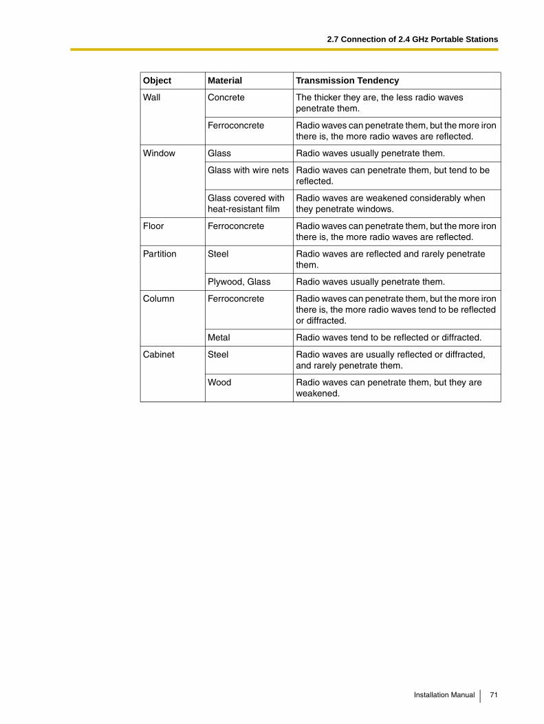
Characteristics of Radio WavesThe transmission of radio waves and the CS coverage area depend on the structure and materials of the building.
Office equipment, such as computers and fax machines, can interfere with radio waves. Such equipment may create noise or interfere with the performance of the PS.
The illustration below shows the special transmitting patterns of radio waves.
1. Radio waves are reflected by objects such as those made of metal.
2. Radio waves are diffracted by objects such as metallic columns.
3. Radio waves penetrate objects such as those made of glass.
Relationships Between Radio Waves and Building Structure and Materials• The CS coverage area is affected more by the building materials and their thickness than
the number of obstacles.
• Radio waves tend to be reflected or diffracted by conductive objects and rarely penetrate them.
• Radio waves tend to penetrate insulated objects and are rarely reflected by them.
• Radio waves penetrate thin objects more than thick objects.
• The table below shows the transmission tendency of radio waves when they reach objects made from various materials.
CS
Column
3. Penetration
2. Diffraction
1. Reflection
70 Installation Manual
2.7 Connection of 2.4 GHz Portable Stations
Object Material Transmission Tendency
Wall Concrete The thicker they are, the less radio waves penetrate them.
Ferroconcrete Radio waves can penetrate them, but the more iron there is, the more radio waves are reflected.
Window Glass Radio waves usually penetrate them.
Glass with wire nets Radio waves can penetrate them, but tend to be reflected.
Glass covered with heat-resistant film
Radio waves are weakened considerably when they penetrate windows.
Floor Ferroconcrete Radio waves can penetrate them, but the more iron there is, the more radio waves are reflected.
Partition Steel Radio waves are reflected and rarely penetrate them.
Plywood, Glass Radio waves usually penetrate them.
Column Ferroconcrete Radio waves can penetrate them, but the more iron there is, the more radio waves tend to be reflected or diffracted.
Metal Radio waves tend to be reflected or diffracted.
Cabinet Steel Radio waves are usually reflected or diffracted, and rarely penetrate them.
Wood Radio waves can penetrate them, but they are weakened.
Installation Manual 71
2.7 Connection of 2.4 GHz Portable Stations
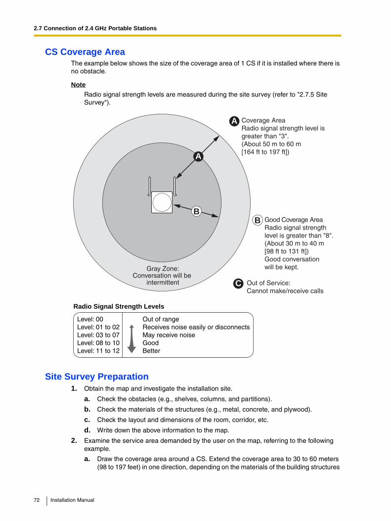
CS Coverage AreaThe example below shows the size of the coverage area of 1 CS if it is installed where there is no obstacle.
Note
Radio signal strength levels are measured during the site survey (refer to "2.7.5 Site Survey").
Site Survey Preparation1. Obtain the map and investigate the installation site.
a. Check the obstacles (e.g., shelves, columns, and partitions).
b. Check the materials of the structures (e.g., metal, concrete, and plywood).
c. Check the layout and dimensions of the room, corridor, etc.
d. Write down the above information to the map.
2. Examine the service area demanded by the user on the map, referring to the following example.
a. Draw the coverage area around a CS. Extend the coverage area to 30 to 60 meters (98 to 197 feet) in one direction, depending on the materials of the building structures
Gray Zone:Conversation will be
intermittent
Coverage AreaRadio signal strength level is greater than "3".(About 50 m to 60 m[164 ft to 197 ft])
Good Coverage AreaRadio signal strengthlevel is greater than "8".(About 30 m to 40 m[98 ft to 131 ft])Good conversationwill be kept.
Out of Service:Cannot make/receive calls
A
B
A
B
Radio Signal Strength Levels
C
Out of rangeReceives noise easily or disconnectsMay receive noiseGoodBetter
Level: 00Level: 01 to 02Level: 03 to 07Level: 08 to 10 Level: 11 to 12
72 Installation Manual
2.7 Connection of 2.4 GHz Portable Stations
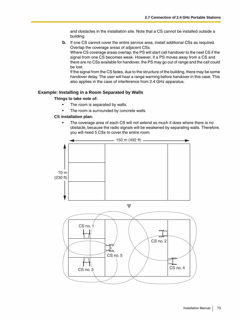
and obstacles in the installation site. Note that a CS cannot be installed outside a building.
b. If one CS cannot cover the entire service area, install additional CSs as required. Overlap the coverage areas of adjacent CSs.Where CS coverage areas overlap, the PS will start call handover to the next CS if the signal from one CS becomes weak. However, if a PS moves away from a CS and there are no CSs available for handover, the PS may go out of range and the call could be lost.If the signal from the CS fades, due to the structure of the building, there may be some handover delay. The user will hear a range warning before handover in this case. This also applies in the case of interference from 2.4 GHz apparatus.
Example: Installing in a Room Separated by WallsThings to take note of:
• The room is separated by walls.
• The room is surrounded by concrete walls.
CS installation plan:
• The coverage area of each CS will not extend as much it does where there is no obstacle, because the radio signals will be weakened by separating walls. Therefore, you will need 5 CSs to cover the entire room.
CS no. 5
CS no. 1
CS no. 2
CS no. 4CS no. 3
70 m(230 ft)
150 m (492 ft)
Installation Manual 73

2.7 Connection of 2.4 GHz Portable Stations
2.7.4 Before Site Survey
Setting and Installing the CS Temporarily for Site Survey1. Switch the Radio Signal Test switch from OFF to ON.
2. Set the CS number switches as desired.
Notes• To see the radio signal strength of more than 1 CS, a CS number must be set for each
CS.
• If more than 1 CS is in Radio Signal Test mode, each CS must have a unique CS number.
CS Number Switch
CS no. 1 CS no. 2 CS no. 3 CS no. 4 CS no. 5 CS no. 6 CS no. 7 CS no. 8 CS no. 9
1
2
3
4
1
2
3
4
1
2
3
4
1
2
3
4
1
2
3
4
1
2
3
4
1
2
3
4
1
2
3
4
1
2
3
4
DIP Switch
1
2
3
4
5
6
OFF ON
Radio Signal Test Switch
74 Installation Manual

2.7 Connection of 2.4 GHz Portable Stations
3. After setting the DIP switch, connect an AC adaptor or battery box to the CS using a power supply adaptor.
4. Install the CS temporarily for the site survey. Install the CS at least 2 m (6.6 ft) above the floor, keeping the antennas in the upright position.
To AC Adaptor (KX-A11/KX-TCA1)/Battery Box (PSZZTD142CE)
Power Supply Adaptor(PSZZ1TDA0142)Modular
Telephone Cord
Installation Manual 75

2.7 Connection of 2.4 GHz Portable Stations
2.7.5 Site Survey
The PS has a Radio Signal Test mode that monitors the state of the radio link to the CS. After installing the CSs temporarily, set the PS to the Radio Signal Test mode and measure each CS coverage area. Then, record the results on the map of the installation site.
Testing the Radio Signal Strength
NoteThe display language for the site survey is only in English.
1. Enter the Radio Signal Test mode.
Using the KX-TD7680
Using the KX-TD7690
Notes*1: CS number and radio signal strength level.
*2: Scan data (test result) number. Empty memory space will be indicated by a number; stored memory space will be indicated by a "-".
Display example:
Press 1, 9, and POWERfor more than 2 seconds.
<< SEARCHING >>CS NO.1 LEVEL:12*1
SAVE:0123456789*2
1 to 9
CS No.1 99
0 to 9
Scan Data No.To store the scan data
0
Display example:
Press 1, 9, and POWERfor more than 2 seconds.
<< SEARCHING >>CS NO.1 LEVEL:12*1
SAVE:0123456789*2
1 to 9
CS No.1 99
0 to 9
Scan Data No.To store the scan data
0
76 Installation Manual

2.7 Connection of 2.4 GHz Portable Stations
2. Measure the radio signal strength by moving to and away from the CS.
a. Move to the CS until the point the radio signal strength level becomes "12".
b. Move away from the CS and identify the CS coverage area within which the radio signal strength level is greater than "8". Draw the area on the map.
c. Move away from the CS and identify the CS coverage area within which the radio signal strength level is greater than "3". Draw the area on the map.
3. Repeat the steps 1 and 2 for other CSs, and relocate the CSs when necessary.
a. Overlap adjacent CS coverage areas where the radio signal strength level is "8" by 5 to 10 meters (16 to 33 feet).
CS no. 1
PS
PS
PS CS NO.1 LEVEL:3
CS NO.1 LEVEL:12
Radio Signal Strength Levels
CS NO.1 LEVEL:8
Out of rangeReceives noise easily or disconnectsMay receive noiseGoodBetter
Level: 00Level: 01 to 02Level: 03 to 07Level: 08 to 10 Level: 11 to 12
5 m to 10 m(16 ft to 33 ft)
CS no. 1 CS no. 2
Installation Manual 77

2.7 Connection of 2.4 GHz Portable Stations
b. Overlap the CS coverage areas of at least 2 CSs at any location in the installation site.
c. Make sure that the radio signal strength level is greater than "3" at any location in the service area demanded by the user.
Referring to the Stored Scan DataUsing the KX-TD7680
Using the KX-TD7690
CS no. 1 CS no. 2
CS no. 3 CS no. 4
Press 1, 9, and POWERfor more than 2 seconds.
0 to 9
Scan Data No.1 9 1
Display example:When there is scan data
When there is no scan data
NO.1CS No.2 LEVEL: 9
NO.0NOT SAVED
To the Desired Scan Data No.
Press 1, 9, and POWERfor more than 2 seconds.
0 to 9
Scan Data No.1 9 1
Display example:When there is scan data
When there is no scan data
NO.1CS No.2 LEVEL: 9
NO.0NOT SAVED
To the Desired Scan Data No.
78 Installation Manual
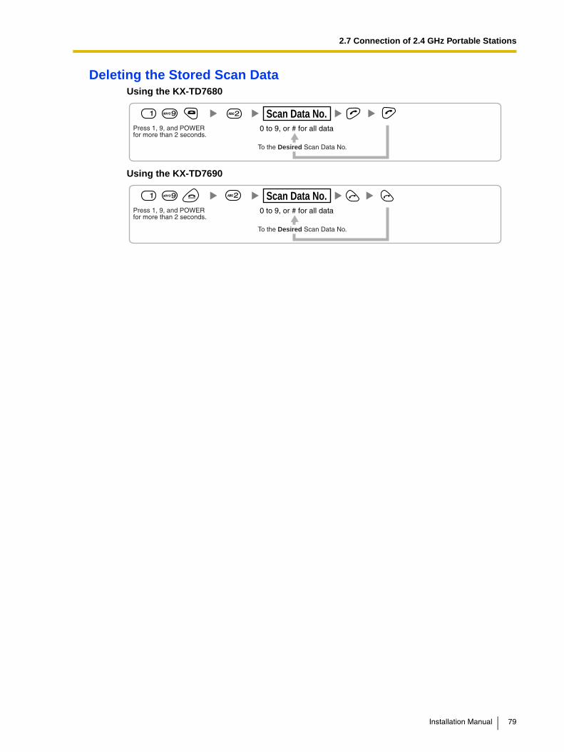
2.7 Connection of 2.4 GHz Portable Stations
Deleting the Stored Scan DataUsing the KX-TD7680
Using the KX-TD7690
Press 1, 9, and POWERfor more than 2 seconds.
0 to 9, or # for all data
Scan Data No.1 9
To the Desired Scan Data No.
2
Press 1, 9, and POWERfor more than 2 seconds.
0 to 9, or # for all data
Scan Data No.1 9
To the Desired Scan Data No.
2
Installation Manual 79

2.7 Connection of 2.4 GHz Portable Stations
2.7.6 After Site Survey
After obtaining the proper measurement results, exit the Radio Signal Test mode before connecting the CS to the PBX.
1. Keep pressing POWER button on the PS until the PS is turned OFF.
2. Disconnect the AC adaptor or battery box from the CS and stop supplying electricity.
3. Switch all DIP switches on the CS from ON to OFF.
1
2
3
4
5
6
OFF ON
80 Installation Manual
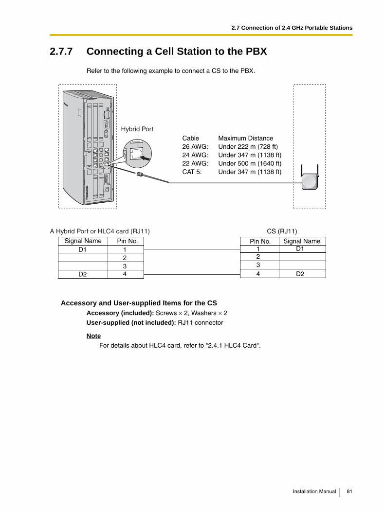
2.7 Connection of 2.4 GHz Portable Stations
2.7.7 Connecting a Cell Station to the PBX
Refer to the following example to connect a CS to the PBX.
Accessory and User-supplied Items for the CSAccessory (included): Screws × 2, Washers × 2
User-supplied (not included): RJ11 connector
NoteFor details about HLC4 card, refer to "2.4.1 HLC4 Card".
A Hybrid Port or HLC4 card (RJ11) CS (RJ11)
Cable Maximum Distance26 AWG: Under 222 m (728 ft)24 AWG: Under 347 m (1138 ft)22 AWG: Under 500 m (1640 ft)CAT 5: Under 347 m (1138 ft)
Signal NameSignal Name Pin No.1234
D1
D2
D1
D2
Pin No.1234
Hybrid Port
Installation Manual 81
2.7 Connection of 2.4 GHz Portable Stations
Connecting the CS1. Connect the cable from a Hybrid Port or the HLC4card to the CS.
2. Pass the cable through the groove of the CS (in any direction depending on your preference).
Modular
To a Hybrid Port,or HLC4 card
To a Hybrid Port,or HLC4 card
TO MAIN UNIT/ PABX
82 Installation Manual
2.7 Connection of 2.4 GHz Portable Stations
Registering the PSThe PS must be registered to the PBX before it can be used. Programming of both the PS and PBX is required. An APT with multiline display (e.g., KX-T7735) is required for the PBX system programming.
Note
For details about system programming using an APT, refer to "2.3.2 PT Programming" and "3.3 PT Programming" in the Feature Guide.
Entering the System Programming ModeAPT (Administrator Level)
PS (Using the KX-TD7680)
PS (Using the KX-TD7690)
Note
means default value throughout this section.
PS Registration
#
= 1234
System Password for Administrator—for PT Programming Programming No.
3 digits
PROGRAM/PAUSE
System Setting Menu
Select "SYSTEM SET".
Press POWER for 2 seconds.
Select"PS PROGRAM".
4 digits
System Lock PasswordIf required
FUNC
System Setting Menu
Select "SYSTEM SETTING".
Press POWER for 2 seconds.
S1 S1
MENU SEL
S1
SEL
Select"PS PROGRAM".
4 digits
System Lock PasswordIf required
ENTR
S1
[690]001 to 028
PS No.1 to 4 digits
To the PSoperationbelow
Extn. No.STORE STORE END
Installation Manual 83

2.7 Connection of 2.4 GHz Portable Stations
When the PS has not been registered yet
When registering the PS for the first time, it is possible to select the desired language for the display. (You do not need to enter the PS system programming mode when registering for the first time.)
Using the KX-TD7680
Using the KX-TD7690
When the PS has already been registered to another PBX
One PS can be registered to a maximum of 4 different PBXs.
Using the KX-TD7680
Using the KX-TD7690
Setting the System LockWhen a system lock has been set, the system lock password will be required for PS system setting.
Using the KX-TD7680
PressPOWER for2 seconds.
Press S3 for 2 seconds.
C.TonePress S2 repeatedly to select the desired language.
[ F2 ] [ F3 ]
PressPOWER for2 seconds.
Press S3 for 2 seconds.
C.TonePress S2 repeatedlyto select the desiredlanguage.
F2 F3
Choose "SYSTEM 1–4".
Select "REGISTRATION".
C.Tone
Choose "SYSTEM 1–4".
Select "REGISTRATION".
S1S1
SEL SEL
C.Tone
Choose "Enable/Disable".Select
"SYSTEM LOCK".
C.Tone
4 digits 4 digitsENABLE
DISABLE
System Lock Password System Lock Password
84 Installation Manual

2.7 Connection of 2.4 GHz Portable Stations
Using the KX-TD7690
Setting the Personal Identification Number (PIN) for PS RegistrationTo prevent registering the PS to a wrong PBX, a PIN for PS registration can be set to the PBX. Before registering the PS to the PBX, register the PIN set to the PBX into the PS. By doing so, the PS will only be registered to the PBX with the matching PIN.
Notes
• By default, the PIN for PS registration is "1234" for both the PBX and PS. Therefore, the PS can be registered to the PBX without setting the PIN.
• The PIN for PS registration will only be used when registering the PS to the PBX. Therefore, even when there is more than 1 PBX with the same PIN near the PS, the PS will not be linked to a different PBX during normal operation after registration.
Setting the PIN for PBX
Setting the PIN for PS
Using the KX-TD7680
Using the KX-TD7690
S1 Choose "Enable/Disable".
SEL
ENTR
S1
S1
S1
S1
CHNG
SEL
ENTR
Select "SYSTEM LOCK".
C.Tone
4 digits 4 digitsENABLE
DISABLE
System Lock Password System Lock Password
[692]1 to 4 digits
PIN for PS Registration
1234STORE STORE END
Select "CHANGE PIN"
C.Tone1 to 4 digits
1234
PIN for PS Registration
Select "CHANGE PIN" S1
ENTR
S1
SEL
C.Tone1 to 4 digits
1234
PIN for PS Registration
Installation Manual 85

2.7 Connection of 2.4 GHz Portable Stations
PS TerminationConfirm the following before canceling the PS registration:
• PS is turned on.
• PS is within the range.
If the registration information is still stored in the PS
Using the KX-TD7680
Using the KX-TD7690
Testing the OperationWalk around the service area while having a conversation using a registered PS. If noise is frequent or conversations disconnect, relocate the CSs or install additional CS.
[691]001 to 028
PS No.
To the PSoperationbelow
If "Rejected" or "Time out" is displayed
STORE STORE
ENDSTORECLEAR
Select the desired item.
Select "DELETESYSTEM".
Select "YES".
C.Tone
Select the desired item.
Select "DELETESYSTEM".
S1S1
SEL SEL
Select "YES".
C.ToneS1
SEL
86 Installation Manual

2.7 Connection of 2.4 GHz Portable Stations
2.7.8 Wall Mounting
1. Place the reference for wall mounting (on the following page) on the wall to mark the 2 screw positions.
2. Install the 2 screws and washers (included) into the wall.
Notes• Make sure that the screw heads are at the same distance from the wall.
• Install the screws perpendicular to the wall.
3. Hook the CS on the screw heads.
Installation Manual 87

2.7 Connection of 2.4 GHz Portable Stations
Reference for Wall MountingPlease copy this page and use as a reference for wall mounting.
Note
When you print out this page, the distance on the paper output may deviate slightly from the measurement indicated above.
Install a screw here.
Install a screw here.
71 mm(2-13/16 in)
88 Installation Manual

2.8 Connection of Doorphones and Door Openers
2.8 Connection of Doorphones and Door Openers
2.8.1 Connection of Doorphones and Door Openers
Maximum of 4 doorphones (KX-T30865) and door openers can be connected to the PBX.
Note
Doorphones and door openers are user-supplied.
Maximum Cabling Distance
Current Limit for door opener: 24 V DC/30 V AC, 1 A maximum
Installing the Doorphone (KX-T30865)1. Loosen the screw to separate the doorphone into 2 halves.
Cable Maximum Distance26 AWG: Under 70 m (230 ft)24 AWG: Under 113 m (371 ft)22 AWG: Under 180 m (590 ft)CAT 5: Under 113 m (371 ft)
Doorphone
Door Opener
Panasonic
Screw
Installation Manual 89

2.8 Connection of Doorphones and Door Openers
2. Pass the wires through the hole in the base cover, and attach the base cover to a wall using 2 screws.
Note
Two kinds of screws are included with KX-T30865. Please choose the appropriate kind for your wall type.
3. Connect the wires to the screws located in the front cover.
4. Re-attach the 2 halves and re-insert the screw.
: when a doorphone plate has been fixed to the wall
: when you wish to install the doorphone directly to the wall
Screw
To terminal box
To terminal box
90 Installation Manual
2.8 Connection of Doorphones and Door Openers
Connection of Doorphones1. Connect DPH4 Card to the terminal boxes using telephone line cords.
Refer to "2.5.1 DPH4 Card" for pin assignments.
2. Connect the wires of doorphones 1 and 3 to the red and green screws on the terminal box.
3. Connect the wires of doorphones 2 and 4 to the yellow and black screws on the terminal box.
PanasonicPanasonic PanasonicPanasonic
YellowRed
Black
Telephone Line Cord
Telephone Line Cord
Green
Doorphone 3 Doorphone 4
Doorphone 1 Doorphone 2
To DPH4 card
Terminal Box
PanasonicPanasonic PanasonicPanasonic
YellowRed
BlackGreen
Installation Manual 91

2.8 Connection of Doorphones and Door Openers
Connection of the Door OpenersUse 10-pin terminal block (included with the card) for connection.
1. While pressing down on the hole at the top of the terminal block using a screwdriver, insert the wire into the side hole as shown below. Repeat this procedure for other door openers.Refer to "2.5.1 DPH4 Card" for pin assignments.
2. Attach the terminal blocks to the connectors of the DPH4 card in the PBX.
Door Opener
To door openers
92 Installation Manual
2.9 Connection of Peripherals
2.9 Connection of Peripherals
2.9.1 Connection of Peripherals
BGM/MOHThe PBX provides Background Music and Music on Hold. Only 1 external music source (e.g., user-supplied radios) can be used by connecting them to the PBX.
CAUTION• Wiring should be done carefully to prevent undue force being exerted on the plug.
Otherwise, music may intermittent.
• An External Music Jack is a SELV port and should only be connected to an approved SELV device.
Note
When the PBX and external music sources are not connected to the same ground, hum noise may be induced into Background Music and Music on Hold.
BGM/Music on Hold
Pager:Amplifier/Speaker
PC Printer
PC
Cable Maximum Distance26 AWG to 22 AWG: Under 10 m (32 ft)CAT 5: Under 10 m (32 ft)
Cable Maximum Distance26 AWG to 22 AWG: Under 10 m (32 ft)CAT 5: Under 10 m (32 ft)
Maximum DistanceUnder 2 m (6 ft)
Maximum DistanceUnder 5 m (16 ft)
Installation Manual 93

2.9 Connection of Peripherals
PagerOnly 1 paging device (user-supplied) can be connected to the PBX.
CAUTIONAn External Paging Jack is a SELV port and should only be connected to an approved SELV device.
PC/Printer (via RS-232C)The PBX is equipped with an RS-232C interface. This interface provides communication between the PBX and the user-supplied devices such as PC or line printers. The RS-232C port is used for system programming, SMDR, diagnostics and external system database storage (save/load) functions.When using special accessories such as cable, the user should use those specified in this installation manual to comply with the limits for a Class B digital device pursuant to the FCC Rules.
NoteUse an RS-232C cross cable for connection between the PBX and PC.
Pin Assignments
Connection ChartsFor connecting a printer/PC with a 9-pin RS-232C connector
No. Signal Name FunctionCircuit Type
EIA CCITT
2 RD (RXD) Receive Data BB 104
3
4
SD (TXD)
ER (DTR)
Transmit Data
Data Terminal Ready
BA
CD
103
108.2
5
6
SG
DR (DSR)
Signal Ground
Data Set Ready
AB
CC
102
107
7
8
RS (RTS)
CS (CTS)
Request To Send
Clear To Send
CA
CB
105
106
6 9
1 5
PBX Printer/PC
Circuit Type(EIA)
SignalName Pin No. Pin No.
SignalName
Circuit Type(EIA)
BB RD (RXD) 2
BA SD (TXD) 3
CD ER (DTR) 4
AB SG 5
CC DR (DSR) 6
CA RS (RTS) 7
CB CS (CTS) 8
2 RD (RXD) BB
3 SD (TXD) BA
4 ER (DTR) CD
5 SG AB
6 DR (DSR) CC
7 RS (RTS) CA
8 CS (CTS) CB
94 Installation Manual

2.9 Connection of Peripherals
For connecting a printer/PC with a 25-pin RS-232C connector
RS-232C Signals
• Receive Data (RXD):…(input)Conveys signals from the printer or the PC.
• Transmit Data (TXD):…(output)Conveys signals from the unit to the printer or the PC. A "Mark" condition is held unless data or BREAK signals are being transmitted.
• Data Terminal Ready (DTR):…(output)This signal line is turned ON by the unit to indicate that it is ON LINE. Circuit ER (DTR) ON does not indicate that communication has been established with the printer or the PC. It is switched OFF when the unit is OFF LINE.
• Signal Ground (SG)Connects to the DC ground of the unit for all interface signals.
• Data Set Ready (DSR):…(input)An ON condition of circuit DR (DSR) indicates the printer or the PC is ready. Circuit DR (DSR) ON does not indicate that communication has been established with the printer or the PC.
• Request To Send (RTS):…(output)This lead is held ON whenever DR (DSR) is ON.
• Clear To Send (CTS):…(input)An ON condition of circuit CS (CTS) indicates that the printer or the PC is ready to receive data from the unit. The unit does not attempt to transfer data or receive data when circuit CS (CTS) is OFF.
• Frame Ground (FG)Connects to the unit frame and the earth ground conductor of the AC power cord.
PBX Printer/PC
Circuit Type(EIA)
SignalName
Pin No.SignalName
Circuit Type(EIA)
BB RD (RXD) 2
BA SD (TXD) 3
CD ER (DTR) 4
AB SG 5
CC DR (DSR) 6
CA RS (RTS) 7
CB CS (CTS) 8
1 FG AA
3 RD (RXD) BB
2 SD (TXD) BA
20 ER (DTR) CD
7 SG AB
5 CS (CTS) CB
6 DR (DSR) CC
CF4 RS (RTS)
Pin No.
Installation Manual 95
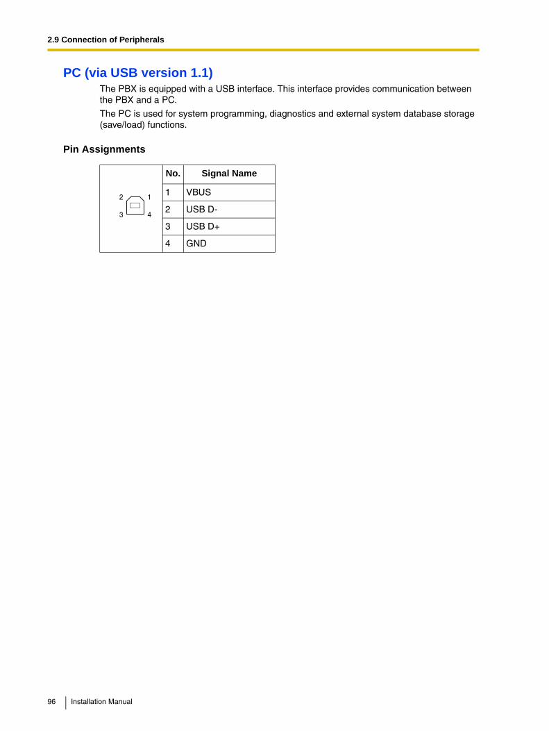
2.9 Connection of Peripherals
PC (via USB version 1.1)The PBX is equipped with a USB interface. This interface provides communication between the PBX and a PC.
The PC is used for system programming, diagnostics and external system database storage (save/load) functions.
Pin Assignments
No. Signal Name
1 VBUS
2 USB D-
3 USB D+
4 GND
2
3
1
4
96 Installation Manual
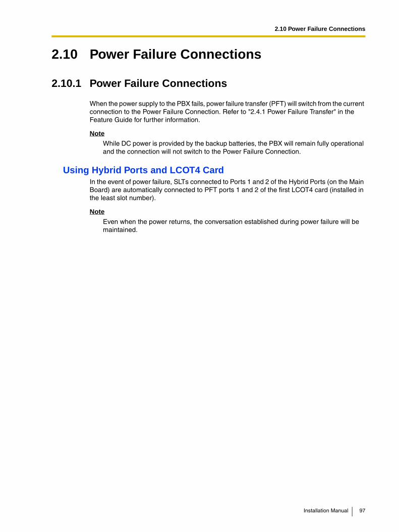
2.10 Power Failure Connections
2.10 Power Failure Connections
2.10.1 Power Failure Connections
When the power supply to the PBX fails, power failure transfer (PFT) will switch from the current connection to the Power Failure Connection. Refer to "2.4.1 Power Failure Transfer" in the Feature Guide for further information.
NoteWhile DC power is provided by the backup batteries, the PBX will remain fully operational and the connection will not switch to the Power Failure Connection.
Using Hybrid Ports and LCOT4 CardIn the event of power failure, SLTs connected to Ports 1 and 2 of the Hybrid Ports (on the Main Board) are automatically connected to PFT ports 1 and 2 of the first LCOT4 card (installed in the least slot number).
Note
Even when the power returns, the conversation established during power failure will be maintained.
Installation Manual 97

2.11 Starting the PBX
2.11 Starting the PBX
2.11.1 Starting the PBX
CAUTION• SD Memory Card must be inserted in the SD Memory Card slot of the main board
before start up.
• Before touching the System Initialize Switch and the Reset Button, discharge static by touching ground or wearing a grounding strap.
• Once you have started the PBX and if you unplug the PBX, do not perform the following procedures to start the PBX again. Otherwise, your programmed data is cleared. To restart the PBX, refer to "4.1.4 Using the Reset Button".
• The PBX will continue to be powered even if the power switch is turned "OFF".
• The power supply cord is used as the main disconnect device, ensure that the socket-outlet is located/installed near the equipment and is easily accessible.
1. Set the System Clear Switch to the "SYSTEM INITIALIZE" position.
RUN Indicator
ALARM Indicator Reset Button
System Initialize Switch
98 Installation Manual

2.11 Starting the PBX
2. Plug the DC connector of the AC adaptor into the DC IN 1.
3. Plug the AC cord into the AC adaptor, and then plug the other end into an AC outlet.
4. Turn on the power switch.
Notes
• For safety reasons, follow the procedures as indicated when turning on the PBX.
AC Adaptor
DC Connector
DC IN 1
21
AC Adaptor
AC Cord
To AC outlet
Power Switch
Installation Manual 99

2.11 Starting the PBX
• For safety reasons, do not stretch, bend, or pinch the AC cord and the DC cable of the AC adaptor.
5. Press the Reset Button with a pointed tool. (The RUN indicator will flash.)
6. While the RUN indicator is flashing (within about 10 s), return the System Clear Switch to the "NORMAL" position. Depending on the configuration, initialization takes about 1 min to 3 min. If successfully executed, the RUN indicator will stop flashing and be kept lit.
All data will be cleared, and the PBX as well as all optional service cards will be initialized to the default values.
NoteUse the same types of AC adaptor and AC cord that are supplied with the PBX only.
LED Indications
Confirming the CO Line ConnectionAfter initialization, program the PBX and establish CO line connection, and then use an APT to confirm it.
To confirm, dial [ ] [3] [7] + CO line number (3 digits) or press S-CO button. You will hear a dial tone if CO line is available and connected.
Turning off the PBXFor safety reasons, make sure to turn off the power switch before unplugging the PBX. To unplug, follow the reverse steps to plug it in.
Indication Color Description
RUN Green OFF: Power Off (includes normal reset)ON: Power On and running (on-line)Flash (60 times per minute): Power On and startingFlash (120 times per minute): Power On and resetting before system initialization
ALARM Red OFF: NormalON: Alarm (CPU stop, alarm for each card)Flash: Alarm (MPR file error in restarting)
100 Installation Manual

Section 3
Guide for the PC Programming Software
This section explains the installation and structure of the PC Programming Software.
Installation Manual 101

3.1 Overview
3.1 Overview
3.1.1 Overview
KX-TAW848 Maintenance Console is designed to serve as an overall system programming reference for the PBX. To program and administer the PBX by PC, you need to install the KX-TAW848 Maintenance Console onto the PC.This manual describes overview and installation of the KX-TAW848 Maintenance Console only.
KX-TAW848 Maintenance Console*1
*1 The contents and design of the software are subject to change without notice.
Menu Bar
Program Menu
102 Installation Manual
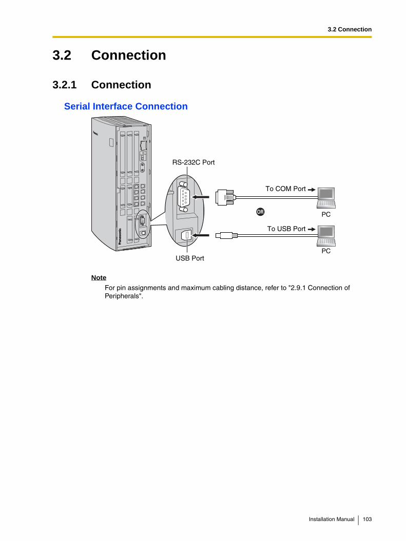
3.2 Connection
3.2 Connection
3.2.1 Connection
Serial Interface Connection
NoteFor pin assignments and maximum cabling distance, refer to "2.9.1 Connection of Peripherals".
PC
PC
To USB Port
To COM Port
USB Port
RS-232C Port
Installation Manual 103
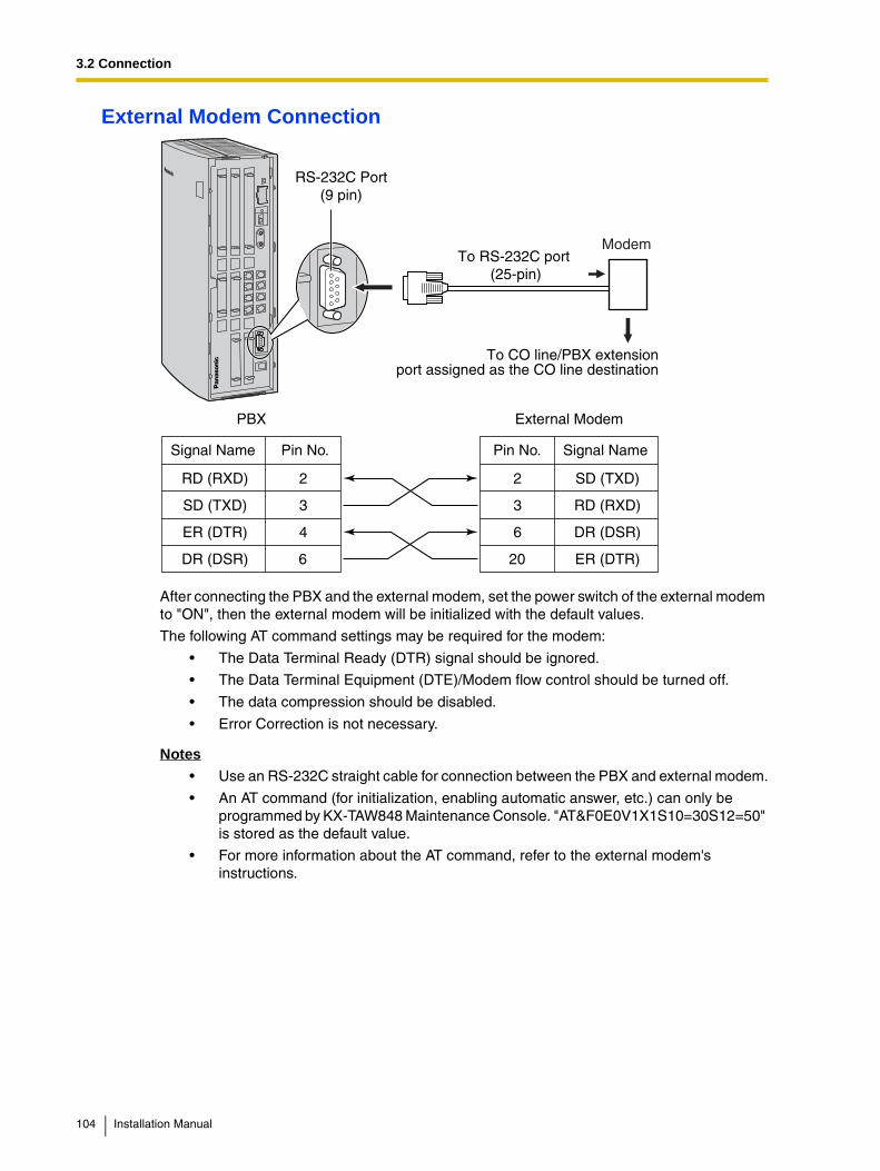
3.2 Connection
External Modem Connection
After connecting the PBX and the external modem, set the power switch of the external modem to "ON", then the external modem will be initialized with the default values.
The following AT command settings may be required for the modem:
• The Data Terminal Ready (DTR) signal should be ignored.
• The Data Terminal Equipment (DTE)/Modem flow control should be turned off.
• The data compression should be disabled.
• Error Correction is not necessary.
Notes• Use an RS-232C straight cable for connection between the PBX and external modem.
• An AT command (for initialization, enabling automatic answer, etc.) can only be programmed by KX-TAW848 Maintenance Console. "AT&F0E0V1X1S10=30S12=50" is stored as the default value.
• For more information about the AT command, refer to the external modem's instructions.
To CO line/PBX extensionport assigned as the CO line destination
ModemTo RS-232C port
(25-pin)
External ModemPBX
Signal Name Pin No. Signal Name
SD (TXD)2
RD (RXD)3
DR (DSR)6
ER (DTR)20
2RD (RXD)
3SD (TXD)
4 ER (DTR)
6DR (DSR)
Pin No.
RS-232C Port(9 pin)
104 Installation Manual

3.3 Installation of the PC Programming Software
3.3 Installation of the PC Programming Software
3.3.1 Installing and Starting the KX-TAW848 Maintenance Console
System RequirementsOperating System
• Microsoft® Windows® 98 SE, Windows Me, Windows 2000, or Windows XP
Hardware
• CPU: Intel® Pentium® 133 MHz or better microprocessor
• RAM: at least 64 megabytes (MB) of free RAM (128 MB recommended)
• HDD: at least 100 MB of hard disc space
Password SecurityTo maintain system security, a password is required to perform system programming. To avoid unauthorized access and possible fraudulent dialing, do not disclose the password.
Warning to the Administrator regarding the system password
1. Please inform the customer of the importance of the password and the possible dangers.
2. To avoid unauthorized access and possible fraudulent dialing, maintain the secrecy of the password.
3. Please change the password periodically.
4. We strongly recommend that a password of 10 digits or 10 characters including digits is used for maximum protection against unauthorized access.
5. If the system password is forgotten, you can examine a backup of the system programming to recall it.
• If you have a backup of the system data, you can find the password by loading the backup system data into a PC and check the password using the programming tool. For more information regarding the backing up of system data, refer to "3.3.4 PBX Maintenance".
• If you do not have a backup of the system data, you have to reset the PBX to its factory defaults and reprogram it, therefore, we recommend maintaining a backup of the system data.
Installation Manual 105

3.3 Installation of the PC Programming Software
Installing the KX-TAW848 Maintenance ConsoleTo install or uninstall the software into Windows 2000 Professional or Windows XP Professional, the user must be grouped either of "Administrators" or "Power Users".
Notes• To install or uninstall the software on a PC running Windows 2000 Professional or
Windows XP Professional, you must be logged in as a user which is in either the "Administrators" or "Power Users" group.
• When the PBX is first connected to the PC via USB, a wizard should appear and ask you to select the appropriate USB driver. Browse for and select the KX-TDA USB driver, which is copied to the local drive during installation.
Starting the KX-TAW848 Maintenance Console and Assigning the Basic Items (Quick Setup)
When you start the KX-TAW848 Maintenance Console with the Installer Level Programmer Code and connect to the PBX for the first time after initialization (with the factory default setting), Quick Setup will launch automatically. During Quick Setup, you will setup the following basic items:
• Date and Time of the PBX. The date and time set on the PC will be used.
• System Password for installer for PC programming.
• Operator extension numbers. Operator extensions for all time modes (day/lunch/break/night) can be assigned.
• Flexible Numbering type to pattern 1 or pattern 2. If pattern 1 (with ) is selected, " " must prefix all feature numbers (except access numbers) when an extension user wants to use a feature.
• Operator call and Idle Line Access/ARS numbers (0 or 9). The feature numbers for operator call and Idle Line Access/ARS can be selected.
• Remote Maintenance Dial Number. Enter the complete telephone number of the PBX (including the country code). When necessary, this number will be used to access the PBX from a remote location for maintenance purposes.
a. Copy the KX-TAW848 Maintenance Console setup file to a local drive on the PC. (Its icon is shown here, on the left.)
b. Double-click the setup file to run the installer.
c. Follow the on-screen instructions provided by the installation wizard.
d. Click [Finish].
e. Click [OK].
106 Installation Manual

3.3 Installation of the PC Programming Software
1. Connect the PC to the PBX with a USB cable.
2. Click "Start" "Programs" "KX-TAW848 Maintenance Console" "KX-TAW848 Maintenance Console".
3. Type the Installer Level Programmer Code (default: INSTALLER), then click [OK].
The Programmer Code authorizes different programming levels, and the Quick Setup is only available when you start the KX-TAW848 Maintenance Console with the Installer Level Programmer Code.
NoteThere are 2 other Programmer Codes with limited authorization: Administrator Level (default: ADMIN), and User Level (default: USER).
4. Click "Connect" "USB" from the menu bar.
Note
To connect to the PBX via USB, the KX-TDA USB driver must be installed on the PC, as explained above in "Installing the KX-TAW848 Maintenance Console".
5. Type the system password for installer (default: 1234), then click [OK] to log-in.
6. Follow the instructions of the wizard and assign the basic items (Quick Setup).
Installation Manual 107

3.3 Installation of the PC Programming Software
Notes
• During long programming sessions, it is highly recommended that you periodically save the system data to the SD Memory Card. If the PBX suffers a sudden power failure or if the system is reset for some reason and all system data is lost, it can be restored from the SD Memory Card.To save the system data to the SD Memory Card, either click the "SD Memory Backup" icon, or exit KX-TAW848 Maintenance Console and click "Yes" to save when prompted.
• When programming PBX data which can be displayed on an analogue proprietary telephone (APT) (extension names, group names, System Speed Dialing names, etc.), it is possible to enter characters which cannot be displayed.Characters which can be displayed on an APT are shown below in the white cells.
• Software features, design, and system requirements are subject to change.
7. The program menu appears. You may now begin programming the PBX.
108 Installation Manual

3.3 Installation of the PC Programming Software
CAUTIONDo not remove the SD Memory Card while it is being accessed. Doing so will corrupt the system data and possibly damage the SD Memory Card.
Installation Manual 109
3.3 Installation of the PC Programming Software
3.3.2 Structure of the KX-TAW848 Maintenance Console
Menu Bar
File
Connect
Tool
Utility DiagnosisFile Transfer PC to PBX (SD Card)File Transfer PBX (SD Card) to PCSD Card File View and LoadMessage File Transfer PC to PBXMessage File Transfer PBX to PCError LogCS InformationPS InformationSystem Reset Reset by the Command
Window
Help
110 Installation Manual

3.3 Installation of the PC Programming Software
3.3.3 PBX Configuration
This section briefly describes how to check the configuration of the PBX using the KX-TAW848 Maintenance Console when PC and the PBX are connected by USB cable.For detailed descriptions of each feature and related PT programming, refer to the on-line help at each screen.
1. Start the KX-TAW848 Maintenance Console (refer to "Starting the KX-TAW848 Maintenance Console and Assigning the Basic Items (Quick Setup)" in "3.3.1 Installing and Starting the KX-TAW848 Maintenance Console").
2. To check the slot condition of the PBX:
a. Double-click "Configuration".
b. Double-click "Slot".
3. To check the PS status:
a. Double-click "Configuration".
b. Double-click "Portable Station".
4. To check other configurations, double-click the other items in the same manner.
Installation Manual 111
3.3 Installation of the PC Programming Software
3.3.4 PBX Maintenance
This section briefly describes how to perform maintenance of the PBX using the KX-TAW848 Maintenance Console when PC and the PBX are connected by USB cable.For detailed descriptions of each feature and related PT programming, refer to the on-line help at each screen.
1. Start the KX-TAW848 Maintenance Console (refer to "Starting the KX-TAW848 Maintenance Console and Assigning the Basic Items (Quick Setup)" in "3.3.1 Installing and Starting the KX-TAW848 Maintenance Console").
2. To diagnose a card:Click "Utility" "Diagnosis" from the menu bar.
3. a. Click "Status" of the desired card and change its status to "OUS".
b. Click "Card Type" of the desired card.The diagnosis screen appears.
To use other utility commands, click the desired item in the step 2 above.
112 Installation Manual

3.3 Installation of the PC Programming Software
File Transfer PC to PBX (SD Card) The program files in the PC are transferred to SD Memory Card of the PBX. Program files in the SD Memory Card is overwritten in this process.
File Transfer PBX (SD Card) to PC The program files in the SD Memory Card are transferred to the PC.
SD Card File View and Load The name, date, time, and size of program files in the SD Memory Card are viewed, then these files are transferred to each CS connected to the PBX.
Message File Transfer PC to PBX The message files for Outgoing Messages in the PC are transferred to all MSG cards. Available only when at least 1 MSG card is installed.
Message File Transfer PBX to PC The message files for Outgoing Messages in the MSG cards are transferred to the PC. Available only when at least 1 MSG card is installed.
Error Log The error log is displayed (for details, refer to "4.1.5 Troubleshooting by Error Log").
CS Information Displays the internal information of the CS.
PS Information Displays the registration information of the PS.
System Reset Reset by the Command
Resets the connected PBX. (It is the same as pushing the Reset Button with the System Initialize Switch in the "NORMAL" position.) After using this command, you have to restart the KX-TAW848 Maintenance Console and connect to the PBX again.
Installation Manual 113

3.3 Installation of the PC Programming Software
114 Installation Manual

Section 4
Troubleshooting
This section provides information on the PBX and telephone troubleshooting.
Installation Manual 115
4.1 Troubleshooting
4.1 Troubleshooting
4.1.1 Installation
PROBLEM PROBABLE CAUSE SOLUTION
Extension does not operate. Bad extension card. Exchange the card for a known working one.
Bad connection between the PBX and telephone.
Take the telephone and plug it into the same extension port using a short telephone cord. If the telephone works, then the connection between the PBX and the telephone must be repaired.
A telephone with an A-A1 relay is connected.
Use a 2-wire cord.
Set the A-A1 relay switch of the telephone to the "OUT" or "OFF" position.
Bad telephone. Take the telephone and plug it into another extension port that is working. If the telephone does not work, replace the telephone.
Improper operation. Press the Reset Button (refer to "4.1.4 Using the Reset Button").
Noise on external paging. Induced noise on the wire between the PBX and the amplifier.
Use a shielded cable as the connection wire between the PBX and amplifier. A short shielded cable is recommended.
Distorted external music. Excessive input level from external music source.
Decrease the output level of the external music source by using the volume control on the music source.
Alternate Calling—Ring/Voice and Live Call Screening (LCS) do not function as set when using a Wireless Phone (KX-T7880/KX-T7885/KX-TD7894/KX-TD7895).
Voice-calling mode and Hands-free mode with LCS are not available with Wireless Phones.
Switch the calling mode to ring-calling.
Set the LCS mode to "Private".
The ALARM indicator on the front of the cabinet turns on red.
A major system error occurs in the PBX.
See the error log using the KX-TAW848 Maintenance Console (refer to "4.1.5 Troubleshooting by Error Log").
116 Installation Manual

4.1 Troubleshooting
4.1.2 Connection
Connection between the PBX and an APT:
Connection between the PBX and an SLT:
Connection between the PBX and an SLT that is polarity-sensitive:
CAUSEThe T/R is connected to the D1/D2.
SOLUTIONUse the correct cord (theinner 2 wires are for T/R and the outer 2 wires are for D1/D2).
D1TR
D2
D1 TR D2
PBX
PBX
PBX
Extension
CAUSEThe T/R is connected to the D1/D2.
SOLUTIONUse the correct cord (the inner 2 wires are for T/R).•D1
TR
D2
TR
Extension
CAUSEThe "T" is connected to the "R".
SOLUTIONReverse the connections ofthe T/R.
D1TR
D2
TR
Extension
Can you dialan extension?
(Continued on the next page.)
No
Yes
If a telephone equipped with an A-A1 relay is connected to the Hybrid IP-PBX, set the A-A1 relay switch of the telephone to "OFF".
Installation Manual 117

4.1 Troubleshooting
Connection between the central office and the PBX:
CAUSECO line is connected to the T2/T1.
CO line is connected to the T2/R1.
SOLUTIONReconnect the CO line tothe T1/R1 or T2/R2 of thetelephone jack using 2-conductor wiring.
T2 R1T1R2
CO line PBX
PBXCO line
T2 R1T1R2
(Continued from theprevious page.)
Can you dialout on a CO line?
No
118 Installation Manual
4.1 Troubleshooting
4.1.3 Operation
PROBLEM PROBABLE CAUSE SOLUTION
• The APT does not ring. • The ringer volume is off. • Turn on the ringer volume.
• During a power failure, extensions connected to ports 1 and 2 of Hybrid Ports do not operate.
• An APT is connected to the extension port.
• The dialing mode (tone or pulse) is incorrect.
• Disconnect the APT and connect an SLT.
• Set the Tone/Pulse switch to the other position.
• Originating an outside call, call transfer, or conference cannot be performed.
• The corresponding CO button does not exist on the APT.
• Program the CO button. Refer to "1.18.2 Flexible Buttons" in the Feature Guide.
• Cannot register the PS. • Wrong Personal Identification Number (PIN) is registered to the PS.
• Register the PIN set to the PBX into the PS.
• CS is not connected properly.
• Make sure that the cable is connected properly with correct pin assignments. Also, make sure that the cable does not make short circuits.
• Switch all DIP switches off.
• PS becomes out of range.
• Cannot make calls using the PS.
• CS is not working. • Make sure that the cable is connected properly with correct pin assignments. Also, make sure that the cable does not make short circuits.
• Switch all DIP switches off.
• Location of CS is not good.
• Locate the CS properly (refer to "2.7.5 Site Survey" ).
• Access system of the PS is not properly set.
• Change the access system setting of the PS to the appropriate system or automatic.
• Noise is frequent while using the PS.
• Conversations disconnect while using the PS.
• Call handover is not working while using the PS.
• PS is out of CS coverage area.
• Locate the CS properly (refer to "2.7.5 Site Survey" ).
• PS stays out of service when the CS status is changed from Out of Service to In Service.
• It may take about 20 s for CS to start up after the status has been changed to In Service.
• Wait until the CS starts up.
Installation Manual 119
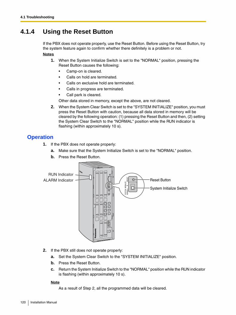
4.1 Troubleshooting
4.1.4 Using the Reset Button
If the PBX does not operate properly, use the Reset Button. Before using the Reset Button, try the system feature again to confirm whether there definitely is a problem or not.
Notes
1. When the System Initialize Switch is set to the "NORMAL" position, pressing the Reset Button causes the following:
• Camp-on is cleared.
• Calls on hold are terminated.
• Calls on exclusive hold are terminated.
• Calls in progress are terminated.
• Call park is cleared.
Other data stored in memory, except the above, are not cleared.
2. When the System Clear Switch is set to the "SYSTEM INITIALIZE" position, you must press the Reset Button with caution, because all data stored in memory will be cleared by the following operation: (1) pressing the Reset Button and then, (2) setting the System Clear Switch to the "NORMAL" position while the RUN indicator is flashing (within approximately 10 s).
Operation1. If the PBX does not operate properly:
a. Make sure that the System Initialize Switch is set to the "NORMAL" position.
b. Press the Reset Button.
2. If the PBX still does not operate properly:
a. Set the System Clear Switch to the "SYSTEM INITIALIZE" position.
b. Press the Reset Button.
c. Return the System Initialize Switch to the "NORMAL" position while the RUN indicator is flashing (within approximately 10 s).
NoteAs a result of Step 2, all the programmed data will be cleared.
RUN Indicator
ALARM Indicator Reset Button
System Initialize Switch
120 Installation Manual
4.1 Troubleshooting
3. If the PBX still does not work:
a. Unplug the PBX.
b. Set the System Initialize Switch to the "SYSTEM INITIALIZE" position.
c. Plug in the PBX after 5 min.
d. Press the Reset Button.
e. Set the System Initialize Switch to the "NORMAL" position while the RUN indicator is flashing (within approximately 10 s).
Installation Manual 121

4.1 Troubleshooting
4.1.5 Troubleshooting by Error Log
When a major system error occurs in the PBX, the ALARM indicator on the front of the cabinet turns on red, and the system logs the error information.
Error Log Display FormatBelow is the display format of the error log. To see the error log using the KX-TAW848 Maintenance Console, refer to "3.3.4 PBX Maintenance".
Example: KX-TAW848 Maintenance Console
Example: Station Message Detail Recording (SMDR)
Description
Item Description
1 Date Date of the error detection
2 Time Time of the error detection
3 Level Major Alarm (MJ ALM):
Errors that affect the whole system operation, or result in system failure
Minor Alarm (MN ALM):
Errors that affect certain part of system operation
4 Error Code Three-digit error code
1 2 4 5 6
3
04/01/01 10:37AM MJ ALM #000 10000 MPR WDT overflow 04/01/01 11:07AM MN ALM #010 10000 AC power down 04/01/01 03:55PM MN ALM #392 10401 Clock master card selected
1 2 3 4 5 6
122 Installation Manual

4.1 Troubleshooting
5 Sub Code Five-digit sub code (1XXYY)
1: Cabinet number
XX: Slot number (00 to 06, 08 to 11)
00: MPR; 01: Hybrid Ports; 02 to 06, 08 to 11: Slots for optional service cards
YY: Physical port number (01 to 16)
For optional service cards that are installed in Slots 08 to 11, sub slot number + port number will be displayed.
Sub slot 1: 11 to 14
Note
When there is no parameter for slot and physical port number, XX and YY will be displayed as "00".Example: Sub code for MPR = 10000
6 Error Message Error description (maximum 36 characters)
Item Description
Installation Manual 123
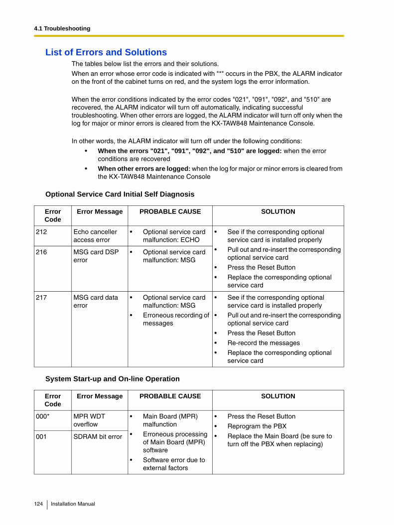
4.1 Troubleshooting
List of Errors and SolutionsThe tables below list the errors and their solutions.
When an error whose error code is indicated with "*" occurs in the PBX, the ALARM indicator on the front of the cabinet turns on red, and the system logs the error information.
When the error conditions indicated by the error codes "021", "091", "092", and "510" are recovered, the ALARM indicator will turn off automatically, indicating successful troubleshooting. When other errors are logged, the ALARM indicator will turn off only when the log for major or minor errors is cleared from the KX-TAW848 Maintenance Console.
In other words, the ALARM indicator will turn off under the following conditions:
• When the errors "021", "091", "092", and "510" are logged: when the error conditions are recovered
• When other errors are logged: when the log for major or minor errors is cleared from the KX-TAW848 Maintenance Console
Optional Service Card Initial Self Diagnosis
System Start-up and On-line Operation
Error Code
Error Message PROBABLE CAUSE SOLUTION
212 Echo canceller access error
• Optional service card malfunction: ECHO
• See if the corresponding optional service card is installed properly
• Pull out and re-insert the corresponding optional service card
• Press the Reset Button
• Replace the corresponding optional service card
216 MSG card DSP error
• Optional service card malfunction: MSG
217 MSG card data error
• Optional service card malfunction: MSG
• Erroneous recording of messages
• See if the corresponding optional service card is installed properly
• Pull out and re-insert the corresponding optional service card
• Press the Reset Button
• Re-record the messages
• Replace the corresponding optional service card
Error Code
Error Message PROBABLE CAUSE SOLUTION
000* MPR WDT overflow
• Main Board (MPR) malfunction
• Erroneous processing of Main Board (MPR) software
• Software error due to external factors
• Press the Reset Button
• Reprogram the PBX
• Replace the Main Board (be sure to turn off the PBX when replacing)
001 SDRAM bit error
124 Installation Manual

4.1 Troubleshooting
002 System Reset • Reset Button is pressed
• Power failure
• Main Board malfunction
• Erroneous processing of Main Board software
• Software error due to external factors
• Ignore if not frequent
• Press the Reset Button
• Reprogram the PBX
• Replace the Main Board (be sure to turn off the PBX when replacing)
010 AC power down • AC power down
• Bad connection or breaking of AC cord
• Check the power supply system
• See if the AC cord is connected properly
• Check the AC cord
• Replace the AC cord (be sure to turn off the PBX when replacing)
011 DC power down • AC power down
• Power supply circuit (Main Board) malfunction
• Detection of over current (short circuit on optional service cards)
• Check the power supply system
• See if the AC cord is connected properly
• Check the AC cord
• Replace the AC cord (be sure to turn off the PBX when replacing)
• Replace the Main Board (be sure to turn off the PBX when replacing)
• Remove the optional service cards and restart the PBX
012* MPR RAM battery low
• Battery out
• Main Board (MPR) malfunction
• Replace the Main Board (be sure to turn off the PBX when replacing)
020* SD file access error
• SD Memory Card malfunction
• Bad connection of SD Memory Card
• Main Board malfunction
• Press the Reset Button
• Reprogram the PBX
• Replace the SD Memory Card
• Replace the Main Board (be sure to turn off the PBX when replacing)
021* SD Memory Card disconnected
• SD Memory Card not installed
• Bad connection of SD Memory Card
• SD Memory Card malfunction
• Main Board malfunction
Error Code
Error Message PROBABLE CAUSE SOLUTION
Installation Manual 125
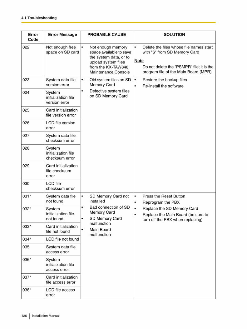
4.1 Troubleshooting
022 Not enough free space on SD card
• Not enough memory space available to save the system data, or to upload system files from the KX-TAW848 Maintenance Console
• Delete the files whose file names start with "$" from SD Memory Card
NoteDo not delete the "PSMPR" file; it is the program file of the Main Board (MPR).
023 System data file version error
• Old system files on SD Memory Card
• Defective system files on SD Memory Card
• Restore the backup files
• Re-install the software
024 System initialization file version error
025 Card initialization file version error
026 LCD file version error
027 System data file checksum error
028 System initialization file checksum error
029 Card initialization file checksum error
030 LCD file checksum error
031* System data file not found
• SD Memory Card not installed
• Bad connection of SD Memory Card
• SD Memory Card malfunction
• Main Board malfunction
• Press the Reset Button
• Reprogram the PBX
• Replace the SD Memory Card
• Replace the Main Board (be sure to turn off the PBX when replacing)
032* System initialization file not found
033* Card initialization file not found
034* LCD file not found
035 System data file access error
036* System initialization file access error
037* Card initialization file access error
038* LCD file access error
Error Code
Error Message PROBABLE CAUSE SOLUTION
126 Installation Manual

4.1 Troubleshooting
090 Over Card Limitation
• Too many optional service cards installed
• Reduce the number of optional service cards
091* PT connection over
• Too many APTs connected
• Reduce the number of APTs
092* CS connection over
• Too many CSs connected
• Reduce the number of CSs
230* Card disconnected
• Optional service card not installed properly
• Optional service card malfunction
• Main Board malfunction
• See if the corresponding optional service card is installed properly
• Pull out and re-insert the corresponding optional service card
• Press the Reset Button
• Replace the corresponding optional service card
• Replace the Main Board (be sure to turn off the PBX when replacing)
234 DPLL clock failure • Main Board malfunction
• Replace the Main Board (be sure to turn off the PBX when replacing)
251 MSG DSP failure • Optional service card malfunction: MSG
• See if the corresponding optional service card is installed properly
• Replace the corresponding optional service card
305* Data Link failure • Data link between the CS and PBX failed
• Check the connection between the CS and PBX
310* Port Link Failure • Voice Processing System malfunction
• Check the Voice Processing System
392 Clock master card selected
• Clock master card has been changed to the one indicated by the sub code
• Check if the proper card is selected as the new clock master card
510* SMDR disconnect • RS-232C cable not connected
• Breaking of RS-232C cable
• Printer (terminal equipment) malfunction
• Check the RS-232C cable
• Check the terminal equipment
Error Code
Error Message PROBABLE CAUSE SOLUTION
Installation Manual 127

4.1 Troubleshooting
128 Installation Manual

Installation Manual 129
Index

Index
Numerics2-Channel Message Card (KX-TAW84891) 20, 624-Port Analog Trunk Card (KX-TAW84880) 20, 534-Port Caller ID Card (KX-TAW84893) 20, 544-Port Doorphone Card (KX-TAW84861) 20, 594-Port Hybrid Extension Card (KX-TAW84870) 20, 554-Port Proprietary Extension Card (KX-TAW84875) 20, 568-Channel Echo Canceller Card (KX-TAW84866) 20, 618-Port Proprietary Extension Card (KX-TAW84876) 20, 588-Port Single Line Telephone Extension Card (KX-TAW84874) 20,
57
AAbout the Other Manuals 9After Site Survey 80
BBasic System Construction 17Before Installation 26Before Site Survey 74
CCharacteristics 23CID4 Card 54Confirming the CO Line Connection 100Connecting a Cell Station to the PBX 81Connection 103, 117Connection of 2.4 GHz Portable Stations 67Connection of Doorphones and Door Openers 89Connection of Extensions 65Connection of Peripherals 93Construction of Main Unit 17CTI—Third Party Call Control 96
DDoor Opener 59, 89Doorphone 59, 89DPH4 Card 59
EECHO8 Card 61EXT-CID Card 63Extension Caller ID Card (KX-TAW84868) 20, 63
FFrame Ground Connection 34
GGeneral Description 21Guide for the PC Programming Software 101
HHandling of the Cables 39HLC4 Card 55
IInstallation 25Installation of the CO Line Cards 53Installation of the Extension Cards 55Installation of the Other Cards 59Installation of the PBX 28Installation of the PC Programming Software 105Installation of the SD Memory Card 33Installation Precautions 26Installing and Starting the KX-TAW848 Maintenance Console 105Installing the KX-TAW848 Maintenance Console 106Installing/Removing the Optional Service Cards 35
KKX-TAW84861 (4-Port Doorphone Card) 20, 59KX-TAW84866 (8-Channel Echo Canceller Card) 20, 61KX-TAW84868 (Extension Caller ID Card) 20, 63KX-TAW84870 (4-Port Hybrid Extension Card) 20, 55KX-TAW84874 (8-Port Single Line Telephone Extension Card) 20,
57KX-TAW84875 (4-Port Proprietary Extension Card) 20, 56KX-TAW84876 (8-Port Proprietary Extension Card) 20, 58KX-TAW84880 (4-Port Analog Trunk Card) 20, 53KX-TAW84891 (2-Channel Message Card) 20, 62KX-TAW84893 (4-Port Caller ID Card) 20, 54KX-TAW84896 (Remote Card) 20, 64
LLCOT4 Card 53Lightning Protector Installation 50
MMain Unit 17Maximum Cabling Distances of the Extension Wiring (Twisted Cable)
65Maximum CO Line and Extension Cards 24Maximum Terminal Equipment 24MSG2 Card 62
NNames and Locations 29
OOpening/Closing the Covers 30Operation 119Options 20Overview 67, 102
PParallel Connection of the Extensions 66Paralleled Telephone Features 16Password Security 105PBX Configuration 111PBX Maintenance 112PLC4 Card 56PLC8 Card 58Portable Station (PS) Features 16
130 Installation Manual
Index
Power Failure Connections 97Procedure Overview 68
RRecommended Lightning Protectors 50Remote Card (KX-TAW84896) 20, 64Removing/Attaching the Front Cover 31RMT Card 64
SSafety Installation Instructions 26SAFETY REQUIREMENTS 4SD Memory Card 33Site Planning 70Site Survey 76SLC8 Card 57Slot Position 35Specifications 21Starting the KX-TAW848 Maintenance Console and Assigning the Basic
Items (Quick Setup) 106Starting the PBX 98Structure of the KX-TAW848 Maintenance Console 110System Capacity 24System Components Table 2System Connection Diagram 18System Highlights 16System Outline 15
TThe Structure of this Manual 9Troubleshooting 115, 116Troubleshooting by Error Log 122Turning off the PBX 100Types of Connectors 43
UUnpacking 28Using the Reset Button 120
VVoice Mail Features 16
WWall Mounting (AC Adaptor) 47Wall Mounting (CS) 87Wall Mounting (KX-TAW848) 44Wiring Precautions 26
Installation Manual 131

Index
132 Installation Manual

Index
Installation Manual 133

Index
134 Installation Manual

Index
Installation Manual 135

Index
136 Installation Manual
Panasonic Consumer Electronics CompanyDivision of Matsushita Electric Corporation of AmericaOne Panasonic WaySecaucus, NJ 07094
Panasonic Sales CompanyDivision of Matsushita Electric of Puerto Rico, Inc.Ave. 65 de Infantería, Km. 9.5 San Gabriel Industrial ParkCarolina, Puerto Rico 00985
http://www.panasonic.com/csd
Copyright:This manual is copyrighted by Panasonic Communications Co., Ltd. (PCC). Under the applicable copyright laws, this manual may not be reproduced in any form, in whole or part, without the prior written consent of PCC and its licensee.
© 2003 Panasonic Communications Co., Ltd. All Rights Reserved.
PSQX3086ZA KK1203EK0