Embed Size (px)
Citation preview

Leqing CuiPrecision Systems Design Lab,
Mechanical Engineering,
University of Michigan,
Ann Arbor, MI 48103
e-mail: [email protected]
Chinedum OkwudireMechatronics and Sustainability Research Lab,
Mechanical Engineering,
University of Michigan,
Ann Arbor, MI 48103
e-mail: [email protected]
Shorya Awtar1
Precision Systems Design Lab,
Mechanical Engineering,
University of Michigan,
Ann Arbor, MI 48103
e-mail: [email protected]
Modeling ComplexNonminimum Phase Zerosin Flexure MechanismsThis paper presents a model to explain complex nonminimum phase (CNMP) zeros seenin the noncollocated frequency response of a large-displacement XY flexure mechanism,which employs multiple double parallelogram flexure modules (DPFMs) as building-blocks. Geometric nonlinearities associated with large displacement along with the kine-matic under-constraint in the DPFM lead to a coupling between the X and Y directiondisplacements. Via a lumped-parameter model that captures the most relevant geometricnonlinearity, it is shown that specific combinations of the operating point (i.e., flexuredisplacement) and mass asymmetry (due to manufacturing tolerances) give rise to CNMPzeros. This model demonstrates the merit of an intentionally asymmetric design over anintuitively symmetric design in avoiding CNMP zeros. Furthermore, a study of how theeigenvalues and eigenvectors of the flexure mechanism vary with the operating point andmass asymmetry indicates the presence of curve veering when the system transitions fromminimum phase to CNMP. Based on this, the hypothesis of an inherent correlationbetween CNMP zeros and curve veering is proposed. [DOI: 10.1115/1.4036032]
1 Introduction and Motivation
This research investigation is motivated by the need to achievelarge range, high precision, and high-speed—all simultaneously—in multi-axis flexure-based motion systems [1,2]. Such capabilityis of practical importance in various applications such as compactand affordable motion stages for semiconductor wafer inspection [3]and microelectromechanical system scanners for high-speed imag-ing [4]. Flexure mechanisms are well-suited for these applicationsbecause of their joint-less construction and inherently high precisiondue to lack of friction and backlash, but present significant tradeoffsbetween large displacement and dynamic performance [5].
Large displacement generally implies transverse deformation ofthe constituent beams in the flexure mechanism greater than 5%of the beam length. This corresponds to several millimeters of dis-placement or motion range for a desktop size flexure-basedmotion system. The relevant system dynamics include natural fre-quencies, mode shapes, and transfer functions between the pointsof actuation and sensing. The closed-loop dynamic performanceobjectives include high bandwidth, good noise and disturbancerejection, good command tracking, small steady-state error, fastpoint-to-point positioning and settling, stability robustness, lowsensitivity to plant variations, etc.
While recent results have demonstrated large range as well ashigh precision in multi-axis flexure mechanisms, achievingdynamic performance remains a challenge [5,6]. Figure 1(a) showsan XY nanopositioning system based on a parallel-kinematic flexuremechanism, designed to achieve a range of 10 mm and precision of625 nm per axis. This mechanism employs a systematic andsymmetric layout of eight double parallelogram flexure module(DPFM). This design provides: a high degree of geometric decou-pling between the X and Y motions of the motion stage resultingin large unconstrained motion range; actuator isolation that allowsthe use of large-stroke single-axis actuators (X actuator and Yactuator); and a complementary endpoint sensing using commonlyavailable sensors (e.g., sensors 1 and 2 for the X direction). Forreference, relevant dimensions of this flexure mechanism are sum-marized in Table 3 in the Appendix.
There are many factors that make the dynamics of such a flexuremechanism challenging. Large displacements lead to geometricnonlinearities in flexure mechanics. Given their dependence on dis-placement, these nonlinearities (and their impact on system dynam-ics) vary with the operating point of the flexure mechanism.Furthermore, large displacements require relatively low stiffness inthe motion directions and therefore low natural frequencies of thefirst few modes. Any attempt to achieve a closed-loop bandwidththat is greater than these low natural frequencies requires a properunderstanding of higher-order dynamics, which is complicated bythe above-mentioned geometric nonlinearities. Furthermore, whilethe symmetric layouts (e.g., Fig. 1(a)) help provide large range,cancel undesired motions, improve space utilization, and enhancequasi-static performance, they also result in multiple closelyspaced modes that are highly sensitive to manufacturing tolerances.This results in parametric uncertainty in the system dynamics.
Figure 1(b) shows an experimental measurement of the noncol-located X direction frequency response from force input Fx to thedisplacement output Xms, for different values of Y displacement(Yms¼ 0, 1.5, 3 mm) [5,7]. One may notice that there are multipleclosely spaced modes around 150 Hz. These correspond to the nat-ural frequency of the secondary mass in each DPFM (discussedfurther in Sec. 3). It is also noteworthy that the X direction fre-quency response changes with the Y direction operating point. Atthe operating points yms¼ 1.5 and 3 mm, the frequency responseshows an additional phase drop of 360 deg and 720 deg, respec-tively, near 150 Hz compared to the nominal operating pointyms¼ 0. The magnitude and phase below and above 150 Hzremains the same for all the operating points. Such observationcannot be explained by minimum phase zero pairs. Thus, suchphase drop is due to complex nonminimum phase (CNMP) zeropairs on the right half plane. This dynamic response was unex-pected, and the existence and number of CNMP zeros seemedarbitrary. From closed-loop performance stand-point, it is wellknown that nonminimum phase (NMP) zeros severely limit band-width, stability robustness, and positioning speed [8,9]. When andwhy do these CNMP zeros appear? Can they be analytically pre-dicted? Do they have physical meaning? Can they be avoided viaphysical system design? Addressing these questions is the motiva-tion behind this investigation.
The paper is organized as follows: Section 2 provides an over-view of the relevant literature on modeling geometric nonlinear-ities in flexure mechanics and NMP zeros in the dynamics of
1Corresponding author.Contributed by the Dynamic Systems Division of ASME for publication in the
JOURNAL OF DYNAMIC SYSTEMS, MEASUREMENT, AND CONTROL. Manuscript receivedJuly 10, 2016; final manuscript received February 2, 2017; published online June 5,2017. Assoc. Editor: Yunjun Xu.
Journal of Dynamic Systems, Measurement, and Control OCTOBER 2017, Vol. 139 / 101001-1Copyright VC 2017 by ASME
Dow
nloaded from https://asm
edigitalcollection.asme.org/dynam
icsystems/article-pdf/139/10/101001/5181324/ds_139_10_101001.pdf by U
niversity of Michigan user on 29 August 2019

flexible systems. Section 3 presents closed-form kinematic rela-tions to capture the relevant nonlinearity and coupling in theDPFM. In Sec. 4, these relations are employed in initially investi-gating the X direction dynamics of a simple representative XYflexure mechanism for different Y operating points. This simplemechanism has all the essential attributes of the more complex XYflexure mechanism of Fig. 1(a), but is more conducive for an ini-tial investigation. A closed-form, parametric dynamic model helpspredict the range of operating points and parametric asymmetrywhere CNMP zeros appear in a noncollocated transfer function ofthis simple flexure mechanism. Similar modeling and CNMP pre-diction is then extended to the XY flexure mechanism of Fig. 1(a).Section 5 explores a potential correlation between these CNMPzeros and the phenomenon of curve veering, which lends some
physical insight into the former. The paper concludes in Sec. 6 witha list of contributions and future tasks. One of the key findings isthat the intentional use of specific parametric asymmetry, which iscounter-intuitive, helps avoid the CNMP zeros altogether.
2 Literature Review
In recent years, there has been a growing body of research liter-ature on the dynamics of flexure mechanisms. Lan et al. [10] pre-sented a distributed-parameter dynamic modeling approach ofelastic flexure mechanisms. The resulting equations of motion inthe time-domain were solved using numerical methods, which arenot very suitable for frequency domain analysis of complex NMPzeros. Akano and Fakinlede [11] used finite element-based nonlin-ear analysis to predict the effect of design parameters on thedynamic performance of flexure mechanisms. While accurate,these methods are computationally intensive and provide limitedphysical insights in the frequency domain. Alternatively, lumped-parameter closed-form modeling approaches have also beeninvestigated. Shilpiekandula and Youcef-Toumi [12] derived alumped-parameter dynamic model of a diaphragm flexure usingTimoshenko beam theory, but did not include geometric nonli-nearities. Awtar and Parmar [5] captured the nonlinear variationin the stiffness of flexure building-blocks to create a lumped-parameter dynamic model of a XY flexure mechanism (Fig. 1(a)),but did not capture the nonlinear coupling between X and Y direc-tions in a DPFM and therefore were unable to predict the NMPbehavior seen experimentally (Fig. 1(b)). The pseudorigid-bodyapproach has also been used for modeling the nonlinear dynamicsof flexure mechanisms [13–15]. While this approach leads to sim-ple lumped-parameter closed-form models, the model parametersare computed via numerical optimization and depend on theboundary conditions of each beam, thereby increasing the model-ing complexity in flexure mechanisms that have a large number ofbeams.
Dynamic modeling of rigid link mechanisms with inherent flex-ibilities, e.g., robotic manipulators, has also been an active area ofresearch. An overview and classification of various modelingapproaches is found in the review paper by Dwivedy and Eberhard[16]. Research in this area includes the study of manipulators withone or more flexible links as well as one or more flexible joints.Various methods including finite elements, assumed modes,lumped parameter, and inverse dynamics have been adopted tostudy the relevant dynamics. This body of work assumes smalldeformation of the links, compared to rigid body motion, which isjustified since the links are designed to be stiff. However, thisassumption fails for flexure mechanisms that provide large defor-mation in their motion directions.
The large deformation of constituent elements or beams in aflexure mechanism results in geometric nonlinearities arising fromarc-length conservation, cross-sectional warping, trapeze effect,and Wagner’s effect in beam mechanics [17–23]. The impact ofthese nonlinearities on the dynamics of flexible beams and struc-tures has been studied extensively, as reported in the reviewpapers by Modi [24] and Pandalai [25]. Furthermore, the dynam-ics and control of flexible beams with an end-mass [26] as well asrotating beams [27] have also been investigated. In further gener-alization, DaSilva formulated the nonlinear differential equationsof motion for Euler–Bernoulli beams experiencing flexure alongtwo principal directions, along with torsion and extension [28].Jonker has formulated a highly generalized model for spatialbeams taking into account relevant nonlinearities, using finiteelement-based multibody dynamics computations [19,29]. Nayfehmodeled the nonlinear transverse vibration of beams with proper-ties that vary along the length [30]. Zavodney and Nayfeh studiedthe nonlinear response of a slender beam with a tip mass to a prin-cipal parametric excitation [31]. Moeenfard and Awtar studied thein-plane flexural and axial vibration of a flexure beam with a tipmass while accounting for the nonlinearity associated with arc-length conservation [32]. While the resulting nonlinear equations
Fig. 1 (a) Large-displacement XY nanopositioning system and(b) X-direction frequency response
101001-2 / Vol. 139, OCTOBER 2017 Transactions of the ASME
Dow
nloaded from https://asm
edigitalcollection.asme.org/dynam
icsystems/article-pdf/139/10/101001/5181324/ds_139_10_101001.pdf by U
niversity of Michigan user on 29 August 2019
of dynamics are solved in time-domain via perturbation, homotopy,or computational methods, this prior work [32] does not pursue thefrequency domain investigation relevant to the present work.
Separately, there exists a significant body of work in the fre-quency domain dynamics of lumped or distributed-parameter flex-ible systems [33–35]. It has been shown that lightly dampedflexible systems with collocated sensor and actuator have alternat-ing poles and zeros along the imaginary axis and are easy to stabi-lize in closed-loop [36,37]. Noncollocated systems do not sharethese attributes and, under certain conditions, exhibit real nonmi-nimum phase (NMP) zeros in the right half plane [38–40]. Spectorand Flashner [38] studied the sensitivities of beam cross section,material properties, and sensor placement on the locations of polesand zeros in flexible systems. They showed that as the sensorplacement is moved away from the actuator, the conjugate zeros,originally located along the imaginary axis, migrate toward infin-ity and then reappear along the real axis. Miu [39] provided aphysical explanation for these real NMP zeros stating that they arerelated to the nonpropagation of energy within the structural sub-system confined by the actuator and sensor. Unlike real NMPzeros, CNMP zeros are relatively rare and have been reported inthe context of a noncollocated acoustical transfer function of aroom [41], as well as in a noncollocated transfer function of alumped-parameter spring–mass system [42,43]. Awtar and Craigidentified CNMP zeros arising due to an electromagnetic couplingbetween a direct current motor and tachometer used in a servosys-tem [44]. These studies on CNMP zeros simply report a mathe-matical or experimental observation, without providing furtherinsight into when or why the zeros appear.
3 Modeling Geometric Nonlinearity in Double
Parallelogram Flexure Modules
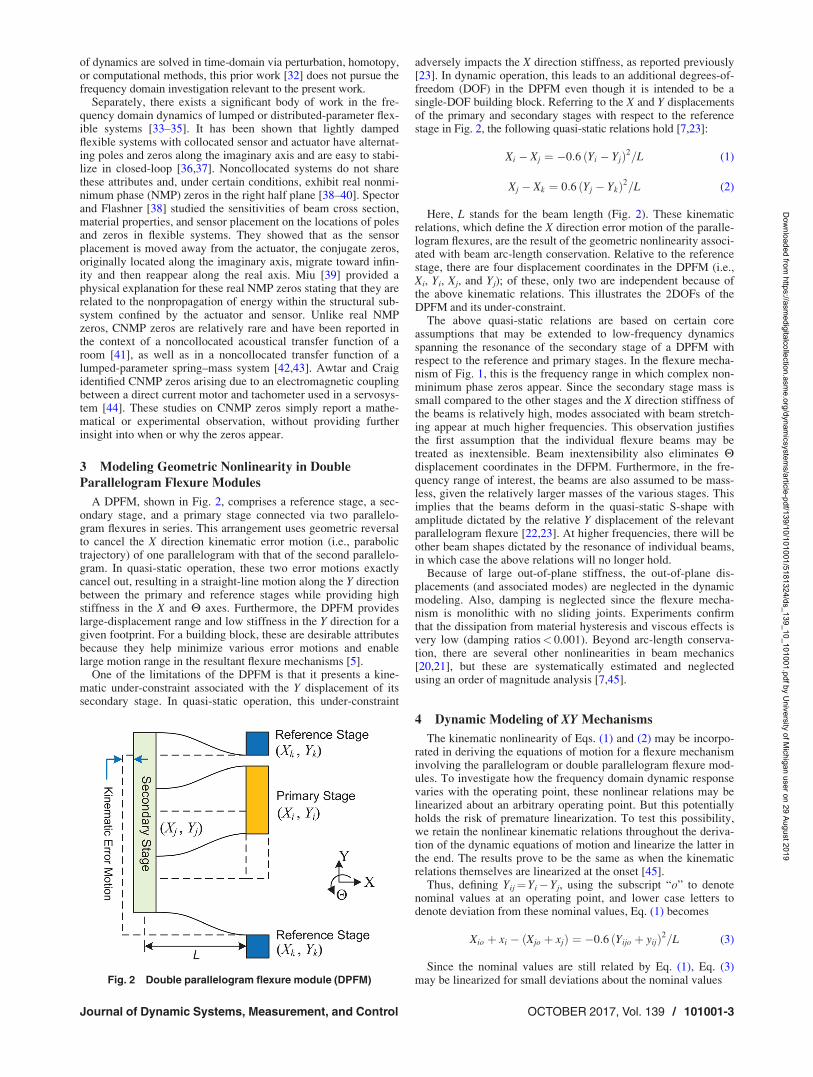
A DPFM, shown in Fig. 2, comprises a reference stage, a sec-ondary stage, and a primary stage connected via two parallelo-gram flexures in series. This arrangement uses geometric reversalto cancel the X direction kinematic error motion (i.e., parabolictrajectory) of one parallelogram with that of the second parallelo-gram. In quasi-static operation, these two error motions exactlycancel out, resulting in a straight-line motion along the Y directionbetween the primary and reference stages while providing highstiffness in the X and H axes. Furthermore, the DPFM provideslarge-displacement range and low stiffness in the Y direction for agiven footprint. For a building block, these are desirable attributesbecause they help minimize various error motions and enablelarge motion range in the resultant flexure mechanisms [5].
One of the limitations of the DPFM is that it presents a kine-matic under-constraint associated with the Y displacement of itssecondary stage. In quasi-static operation, this under-constraint
adversely impacts the X direction stiffness, as reported previously[23]. In dynamic operation, this leads to an additional degrees-of-freedom (DOF) in the DPFM even though it is intended to be asingle-DOF building block. Referring to the X and Y displacementsof the primary and secondary stages with respect to the referencestage in Fig. 2, the following quasi-static relations hold [7,23]:
Xi � Xj ¼ �0:6 ðYi � YjÞ2=L (1)
Xj � Xk ¼ 0:6 ðYj � YkÞ2=L (2)
Here, L stands for the beam length (Fig. 2). These kinematicrelations, which define the X direction error motion of the paralle-logram flexures, are the result of the geometric nonlinearity associ-ated with beam arc-length conservation. Relative to the referencestage, there are four displacement coordinates in the DPFM (i.e.,Xi, Yi, Xj, and Yj); of these, only two are independent because ofthe above kinematic relations. This illustrates the 2DOFs of theDPFM and its under-constraint.
The above quasi-static relations are based on certain coreassumptions that may be extended to low-frequency dynamicsspanning the resonance of the secondary stage of a DPFM withrespect to the reference and primary stages. In the flexure mecha-nism of Fig. 1, this is the frequency range in which complex non-minimum phase zeros appear. Since the secondary stage mass issmall compared to the other stages and the X direction stiffness ofthe beams is relatively high, modes associated with beam stretch-ing appear at much higher frequencies. This observation justifiesthe first assumption that the individual flexure beams may betreated as inextensible. Beam inextensibility also eliminates Hdisplacement coordinates in the DFPM. Furthermore, in the fre-quency range of interest, the beams are also assumed to be mass-less, given the relatively larger masses of the various stages. Thisimplies that the beams deform in the quasi-static S-shape withamplitude dictated by the relative Y displacement of the relevantparallelogram flexure [22,23]. At higher frequencies, there will beother beam shapes dictated by the resonance of individual beams,in which case the above relations will no longer hold.
Because of large out-of-plane stiffness, the out-of-plane dis-placements (and associated modes) are neglected in the dynamicmodeling. Also, damping is neglected since the flexure mecha-nism is monolithic with no sliding joints. Experiments confirmthat the dissipation from material hysteresis and viscous effects isvery low (damping ratios< 0.001). Beyond arc-length conserva-tion, there are several other nonlinearities in beam mechanics[20,21], but these are systematically estimated and neglectedusing an order of magnitude analysis [7,45].
4 Dynamic Modeling of XY Mechanisms
The kinematic nonlinearity of Eqs. (1) and (2) may be incorpo-rated in deriving the equations of motion for a flexure mechanisminvolving the parallelogram or double parallelogram flexure mod-ules. To investigate how the frequency domain dynamic responsevaries with the operating point, these nonlinear relations may belinearized about an arbitrary operating point. But this potentiallyholds the risk of premature linearization. To test this possibility,we retain the nonlinear kinematic relations throughout the deriva-tion of the dynamic equations of motion and linearize the latter inthe end. The results prove to be the same as when the kinematicrelations themselves are linearized at the onset [45].
Thus, defining Yij¼Yi� Yj, using the subscript “o” to denotenominal values at an operating point, and lower case letters todenote deviation from these nominal values, Eq. (1) becomes
Xio þ xi � ðXjo þ xjÞ ¼ �0:6 ðYijo þ yijÞ2=L (3)
Since the nominal values are still related by Eq. (1), Eq. (3)may be linearized for small deviations about the nominal valuesFig. 2 Double parallelogram flexure module (DPFM)
Journal of Dynamic Systems, Measurement, and Control OCTOBER 2017, Vol. 139 / 101001-3
Dow
nloaded from https://asm
edigitalcollection.asme.org/dynam
icsystems/article-pdf/139/10/101001/5181324/ds_139_10_101001.pdf by U
niversity of Michigan user on 29 August 2019
xi � xj ¼ �1:2 ðYijo=LÞ yij¢� a � yij (4)
Here, a is a coupling coefficient that depends on the operatingpoint Yijo and captures the coupling between the X and Y axis dis-placement coordinates.
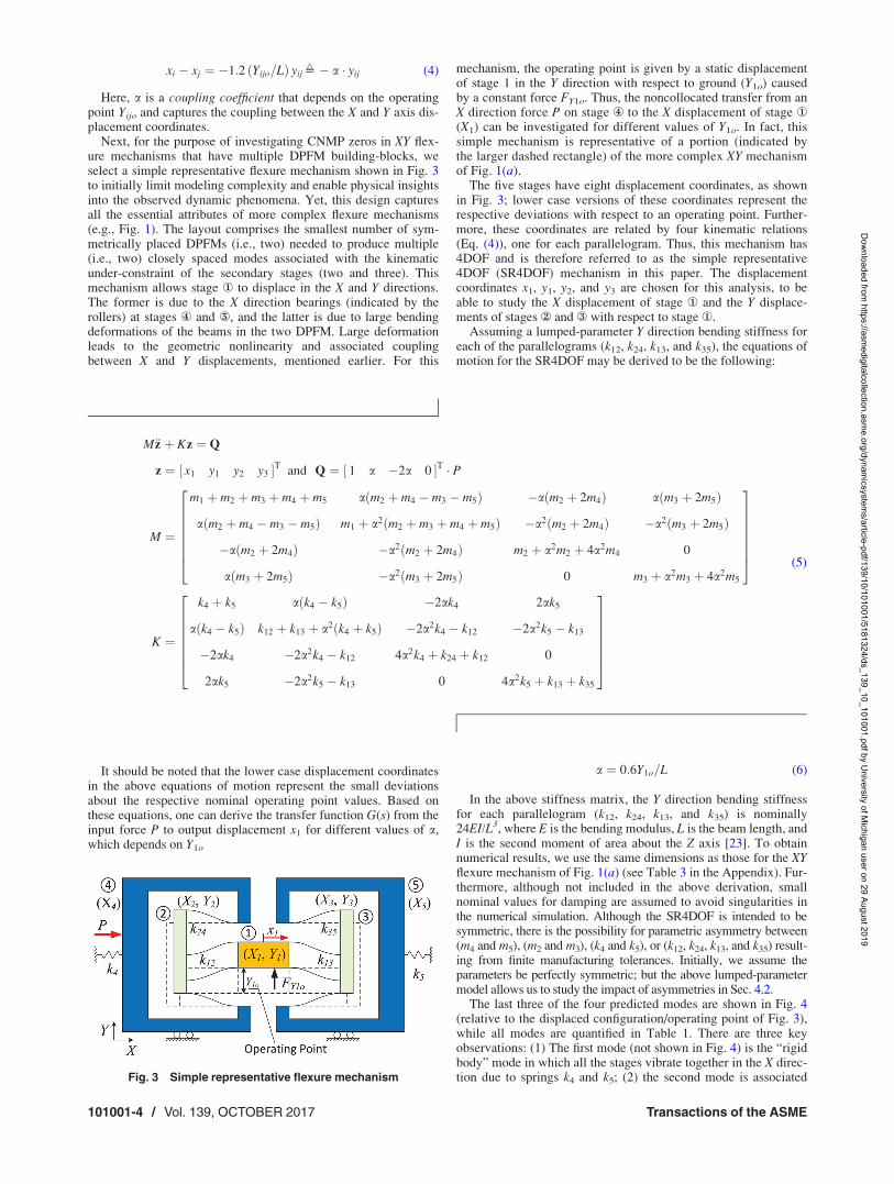
Next, for the purpose of investigating CNMP zeros in XY flex-ure mechanisms that have multiple DPFM building-blocks, weselect a simple representative flexure mechanism shown in Fig. 3to initially limit modeling complexity and enable physical insightsinto the observed dynamic phenomena. Yet, this design capturesall the essential attributes of more complex flexure mechanisms(e.g., Fig. 1). The layout comprises the smallest number of sym-metrically placed DPFMs (i.e., two) needed to produce multiple(i.e., two) closely spaced modes associated with the kinematicunder-constraint of the secondary stages (two and three). Thismechanism allows stage ‹ to displace in the X and Y directions.The former is due to the X direction bearings (indicated by therollers) at stages fl and �, and the latter is due to large bendingdeformations of the beams in the two DPFM. Large deformationleads to the geometric nonlinearity and associated couplingbetween X and Y displacements, mentioned earlier. For this
mechanism, the operating point is given by a static displacementof stage 1 in the Y direction with respect to ground (Y1o) causedby a constant force FY1o. Thus, the noncollocated transfer from anX direction force P on stage fl to the X displacement of stage ‹
(X1) can be investigated for different values of Y1o. In fact, thissimple mechanism is representative of a portion (indicated bythe larger dashed rectangle) of the more complex XY mechanismof Fig. 1(a).
The five stages have eight displacement coordinates, as shownin Fig. 3; lower case versions of these coordinates represent therespective deviations with respect to an operating point. Further-more, these coordinates are related by four kinematic relations(Eq. (4)), one for each parallelogram. Thus, this mechanism has4DOF and is therefore referred to as the simple representative4DOF (SR4DOF) mechanism in this paper. The displacementcoordinates x1, y1, y2, and y3 are chosen for this analysis, to beable to study the X displacement of stage ‹ and the Y displace-ments of stages › and fi with respect to stage ‹.
Assuming a lumped-parameter Y direction bending stiffness foreach of the parallelograms (k12, k24, k13, and k35), the equations ofmotion for the SR4DOF may be derived to be the following:
M€z þ Kz ¼ Q
z ¼ ½ x1 y1 y2 y3 �T and Q ¼ ½ 1 a �2a 0 �T � P
M ¼
m1 þ m2 þ m3 þ m4 þ m5 aðm2 þ m4 � m3 � m5Þ �aðm2 þ 2m4Þ aðm3 þ 2m5Þ
aðm2 þ m4 � m3 � m5Þ m1 þ a2ðm2 þ m3 þ m4 þ m5Þ �a2ðm2 þ 2m4Þ �a2ðm3 þ 2m5Þ
�aðm2 þ 2m4Þ �a2ðm2 þ 2m4Þ m2 þ a2m2 þ 4a2m4 0
aðm3 þ 2m5Þ �a2ðm3 þ 2m5Þ 0 m3 þ a2m3 þ 4a2m5
26666664
37777775
K ¼
k4 þ k5 aðk4 � k5Þ �2ak4 2ak5
aðk4 � k5Þ k12 þ k13 þ a2ðk4 þ k5Þ �2a2k4 � k12 �2a2k5 � k13
�2ak4 �2a2k4 � k12 4a2k4 þ k24 þ k12 0
2ak5 �2a2k5 � k13 0 4a2k5 þ k13 þ k35
26666664
37777775
(5)
It should be noted that the lower case displacement coordinatesin the above equations of motion represent the small deviationsabout the respective nominal operating point values. Based onthese equations, one can derive the transfer function G(s) from theinput force P to output displacement x1 for different values of a,which depends on Y1o
a ¼ 0:6Y1o=L (6)
In the above stiffness matrix, the Y direction bending stiffnessfor each parallelogram (k12, k24, k13, and k35) is nominally24EI/L3, where E is the bending modulus, L is the beam length, andI is the second moment of area about the Z axis [23]. To obtainnumerical results, we use the same dimensions as those for the XYflexure mechanism of Fig. 1(a) (see Table 3 in the Appendix). Fur-thermore, although not included in the above derivation, smallnominal values for damping are assumed to avoid singularities inthe numerical simulation. Although the SR4DOF is intended to besymmetric, there is the possibility for parametric asymmetry between(m4 and m5), (m2 and m3), (k4 and k5), or (k12, k24, k13, and k35) result-ing from finite manufacturing tolerances. Initially, we assume theparameters be perfectly symmetric; but the above lumped-parametermodel allows us to study the impact of asymmetries in Sec. 4.2.
The last three of the four predicted modes are shown in Fig. 4(relative to the displaced configuration/operating point of Fig. 3),while all modes are quantified in Table 1. There are three keyobservations: (1) The first mode (not shown in Fig. 4) is the “rigidbody” mode in which all the stages vibrate together in the X direc-tion due to springs k4 and k5; (2) the second mode is associatedFig. 3 Simple representative flexure mechanism
101001-4 / Vol. 139, OCTOBER 2017 Transactions of the ASME
Dow
nloaded from https://asm
edigitalcollection.asme.org/dynam
icsystems/article-pdf/139/10/101001/5181324/ds_139_10_101001.pdf by U
niversity of Michigan user on 29 August 2019

with the in-phase Y direction vibrations of stages ‹, ›, and fi;and (3) the third and fourth modes are primarily associated withthe Y direction vibrations of the two secondary stages (› and fi)in the opposite and same directions, respectively, with natural fre-quencies close to each other.
The third and fourth modes arise due to the under-constrainedsecondary stages in the DPFM. When Y1o¼ 0 (i.e., a¼ 0), thevibration of the secondary stages does not cause any X directionmotion of stage ‹. Therefore, these two modes are unobservablein the G(s) transfer function. However, when Y1o 6¼ 0, the X and Ydisplacements of the DPFMs get coupled, which affects the thirdand fourth modes differently. For the third mode, the Y vibrationof the two secondary stages is coupled to the X vibration of stage‹. However, in the fourth mode, the two secondary stages havethe same vibration magnitude and phase in the Y direction, which
results in a cancelation of the coupling at stage ‹ in the X direc-tion. Instead, the coupling results in X direction vibrations atstages fl and � (Fig. 4(c)). Thus, when parameters are symmetricbut Y1o 6¼ 0, the third mode shows up in the G(s) transfer function,while the fourth mode remains unobservable.
4.1 Parametric Asymmetry and Complex NonminimumPhase Zeros. While the SR4DOF was assumed to be perfectlysymmetric so far, some parametric asymmetry is inevitable in apractical situation due to manufacturing tolerances. Using theabove lumped-parameter model, we varied parametric asymmetryover a 65% range for (m4 and m5) and (k4 and k5). This did nothave much of an effect on the flexure mechanism dynamics interms of mode shapes and transfer functions. But an asymmetry in(k12, k24, k13, and k35) or (m2 and m3) impacts the vibrations of thesecondary stages (i.e., third and fourth modes) and therefore theoverall flexure mechanism. Of the two sets of parameters, themass parameter is more sensitive. When the DPFM is used as abuilding block, its secondary stage size and mass are minimizedto reduce footprint and raise the resonance frequency at which itvibrates. For example, in the XY flexure mechanisms of Figs. 1(a)and 3, the nominal mass of the secondary stage is 18 g. Therefore,even a small additional mass such as 0.9 g results in a relativelylarge variation (5%). Therefore, in this section, we investigatehow an asymmetry in masses, Dm23 (¼m2/m3� 1), affects thedynamics of SR4DOF.
As seen via the respective eigenvectors in Table 1, the impactof nonzero Dm23 on the first and second modes is minimal. Thismass asymmetry primarily impacts the vibration of the two sec-ondary stages, which directly influence the third and fourthmodes. As noted earlier, the fourth mode of the SR4DOF flexuremechanism is unobservable in the transfer function G(s) for anyY1o (zero or nonzero) when Dm23¼ 0. However, for a small para-metric asymmetry, e.g., Dm23¼ 5%, the two secondary stageshave different vibration magnitudes as seen in the eigenvector inTable 1. Thus, the X direction coupling no longer cancels out atstage ‹, and the fourth mode appears in G(s). Similarly, theimpact of Dm23¼ 5% on the third mode is significant.
G(s) is plotted in Fig. 5 as Y1o varies from 0% to 5%, forDm23¼ 0% and 5%. Key observations are: (1) As expected, thefourth mode is unobservable when Dm23¼ 0 but appears whenDm23 ¼ 5%. (2) The natural frequencies of the third and fourthmodes drop as Y1o increases. As the X vibration of stage ‹ getsincreasingly coupled with the Y vibration of the secondary stages,the modal mass increases more than the modal stiffness, resultingin reduced natural frequencies. (3) A 360 deg phase drop isobserved at around 150 Hz in the asymmetric case (Dm23¼ 5%)when Y1o¼ 5% but not in a symmetric case (Dm23¼ 0%). In thelatter case, the phase drop due to the complex pole pair (thirdmode) is offset by a phase rise due to the complex zero pair(“valley”), resulting in no net phase drop. For the asymmetric case,there are two stable complex pole pairs (third and fourth modes),each contributing 180 deg phase drop. But since the overall phasedrop is 360 deg, this implies that there is no phase rise or drop atthe valley even though there are two pairs of complex zeros at inthis frequency region (�153 Hz). This indicates the presence of aquartet of complex zeros, with one pair in the left half plane andthe second pair in the right half plane, thereby contributing no net
Fig. 4 Mode shapes of the SR4DOF. The black arrows indicatethe relative motion direction of each stage. (a) Second mode,(b) third mode, and (c) fourth mode.
Table 1 Eigenvectors of the SR4DOF mechanism at operating point Y1o 5 5% of L
Dm23¼ 0% f1¼ 18.2 Hz f2¼ 27.6 Hz f3¼ 153.2 Hz f4¼ 154.3 Hz Dm23¼ 5% f1¼ 18.2 Hz f2¼ 27.6 Hz f3¼ 150.1 Hz f4¼ 153.9 Hz
x1 0.9999 0 �0.0231 0 x1 0.9999 �0.0000 �0.0189 �0.0139y1 0 0.8075 0 0.0481 y1 0.0000 0.8073 0.0294 �0.0387y2 0.0068 0.4171 �0.7069 �0.7063 y2 �0.0068 0.4176 �0.9845 0.1384y3 �0.0068 0.4171 0.7069 �0.7063 y3 0.0068 0.4169 0.1718 0.9895
Journal of Dynamic Systems, Measurement, and Control OCTOBER 2017, Vol. 139 / 101001-5
Dow
nloaded from https://asm
edigitalcollection.asme.org/dynam
icsystems/article-pdf/139/10/101001/5181324/ds_139_10_101001.pdf by U
niversity of Michigan user on 29 August 2019

phase change. This is an important observation because it suggeststhat CNMP zeros can arise at certain combinations of operatingpoints and parametric asymmetry.
4.2 Existence of Complex Nonminimum Phase Zeros.Next, we proceed to analytically determine the conditions underwhich CNMP zeros arise. Based on modal decomposition, thetransfer function G(s) may be written as follows, where bi is themodal residue and xi is the corresponding natural frequency:
G sð Þ ¼X4
i¼1
bi
s2 þ x2i
¼u¢s2 b3u3 þ b2u2 þ b1uþ b0
a4u4 þ a3u3 þ a2u2 þ a1uþ a0
¼ N uð ÞD uð Þ
(7)
The decomposed form can also be expressed via a numeratorN(u) and a denominator D(u), each a polynomial. Note that thereare no odd power s terms because damping is ignored. If N(u),which is a cubic polynomial, has two complex conjugate roots, thenG(s) will have a quartet of complex zeros. Two of these zeros will bein the right half plane (i.e., CNMP zeros). For this to happen, the fol-lowing inequality in the coefficients of N(u) has to hold [46]:
D ¼ 18b3b2b1b0 � 4b32b0 þ b2
2b21 � 4b3b3
1 � 27b23b2
0 < 0 (8)
Therefore, this is the mathematical condition for the existenceof CNMP zeros in the G(s) transfer function. Shown in Fig. 6, D isplotted in a contour map against a range of operating pointsand parametric asymmetry values for the SR4DOF flexure mecha-nism. The color in the contour map represents the magnitude of D:red represents higher positive values, blue represents lower posi-tive values, and the black region represents the conditions forwhich D becomes negative, indicating the presence of CNMPzeros. This particular mechanism is seen to be very sensitive topositive asymmetry, i.e., if m2 is greater than m3 even by a smallamount, then CNMP zeros arise in specific ranges of Y1o. How-ever, if m2<m3, then the entire operating range is free of CNMPzeros. The reason for such asymmetric behavior is due to thephysical asymmetry introduced by the actuator placement inFig. 3.
With this finding, we are able to replicate via modeling someaspects of the NMP phenomenon previously observed experimen-tally (Fig. 1(b)). Although, for this study, we intentionally chose theSR4DOF mechanism to keep modeling complexity and assump-tions minimal, it is representative of the more complex designs inthat it incorporates the key attributes of DPFM building-blocks(with their under-constrained secondary stages), geometrically sym-metric design, large displacements leading to nonlinear couplingbetween axes, noncollocated transfer functions, and parametricasymmetry.
In the design of multi-DOF flexure mechanisms, it is a commonguideline to employ symmetric and/or periodic geometries to can-cel undesired motion, improve space utilization, and enhancequasi-static performance [1]. However, the above dynamic modelfor the SR4DOF mechanism indicates that a perfectly symmetriclayout is sensitive to parametric asymmetry, which is likely tooccur due to manufacturing tolerances and can give rise to CNMPzeros. But if the design is intentionally made asymmetric (i.e., ifDm23 is sufficiently negative), then CNMP zeros can be avoidedeven if there are finite manufacturing tolerances.
This also shows that one can choose the springs in the flexuremechanism (i.e., beam flexures dimensions and layout) to be sym-metric to achieve the desired quasi-static performance, whilechoose certain masses to be asymmetric which provides thedesired dynamic performance without impacting quasi-static per-formance. This combination of symmetry in certain attributes andasymmetry in others is rather counter-intuitive but helps meetboth quasi-static and dynamic performance goals.
With CNMP zeros thus eliminated via physical design, we alsocreate the possibility of achieving closed-loop bandwidth higherthan 150 Hz, while maintaining robustness, in the SR4DOF flex-ure mechanism. This would have been impossible in the presenceof CNMP zeros at around 150 Hz.
4.3 Modeling a Complex XY Mechanism. So far, we mod-eled the SR4DOF flexure mechanism to predict CNMP zeros ataround 150 Hz. Next, we extend this modeling approach to themore complex (and practically relevant) XY flexure mechanism ofFig. 1(a). The transfer function X actuator force Fx to the X dis-placement of the motion stage Xms is investigated. The Y actuatoris used to provide a constant force Fyo to achieve various Y direc-tion operating points Ymso. There are 13 rigid stages in this case,each with an X and Y displacement coordinate. Each of the 16parallelogram flexures provides one kinematic relation betweenrelative X and Y coordinates. Therefore, the model has ten inde-pendent DOFs, which results in the same number of equations ofmotion, natural frequencies, and mode shapes. There is a rigidbody X vibration mode, a rigid body Y vibration mode, and eightmodes associated with the vibration of the secondary stages (allaround 150 Hz) in the eight DPFM. Next, we arbitrarily vary thesesecondary stage masses with respect to their nominal value anduse the model to predict the 0 deg/360 deg/720 deg phase dropFig. 6 Contour map of D function
Fig. 5 G(s) transfer function for different operating points (Y1o)and mass asymmetry (Dm23)
101001-6 / Vol. 139, OCTOBER 2017 Transactions of the ASME
Dow
nloaded from https://asm
edigitalcollection.asme.org/dynam
icsystems/article-pdf/139/10/101001/5181324/ds_139_10_101001.pdf by U
niversity of Michigan user on 29 August 2019
seen in Fig. 1(b) and the existence of CNMP zeros. The secondarystages are identified by the subscript a–h, as shown in Fig. 1(a).We present three cases in Table 2 with different combinations ofsecondary stage mass variations that result in the three differentphase drops. Thus, we are able to analytically predict the seeminglyunexplained phenomena observed experimentally in Fig. 1(b).
5 Possible Relation Between Complex Nonminimum
Phase Zeros and Curve Veering
As noted earlier, the SR4DOF mechanism considered in thispaper has a symmetric and repetitive geometry, which leads tomultiple closely spaced modes (i.e., the third and fourth modesshown in Table 1). Furthermore, these modes vary with the oper-ating point and parametric asymmetry. The operating point deter-mines the extent of the cross-axis coupling between X and Ydisplacements, thus building a connection between the third andfourth modes. All these features make the phenomenon of curveveering (or mode veering) potentially relevant in this study.
Curve veering occurs when the eigenvalue loci of two closelyspaced modes in a system approach each other and then diverge,as a result of parameter variation [47]. The point in the parameterspace where the two modes are the closest is called the veeringpoint. The special case when the two modes intersect at the veer-ing point is called mode crossing [48]. In the vicinity of the veer-ing point, eigenvectors undergo dramatic changes. As a result, thesystem could become so-called “critically configured” meaningthat small changes in a system parameter could cause largechanges in system response [49].
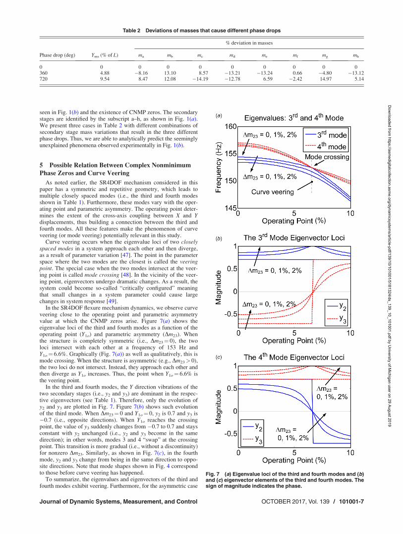
In the SR4DOF flexure mechanism dynamics, we observe curveveering close to the operating point and parametric asymmetryvalue at which the CNMP zeros arise. Figure 7(a) shows theeigenvalue loci of the third and fourth modes as a function of theoperating point (Y1o) and parametric asymmetry (Dm23). Whenthe structure is completely symmetric (i.e., Dm23¼ 0), the twoloci intersect with each other at a frequency of 153 Hz andY1o¼ 6.6%. Graphically (Fig. 7(a)) as well as qualitatively, this ismode crossing. When the structure is asymmetric (e.g., Dm23> 0),the two loci do not intersect. Instead, they approach each other andthen diverge as Y1o increases. Thus, the point when Y1o¼ 6.6% isthe veering point.
In the third and fourth modes, the Y direction vibrations of thetwo secondary stages (i.e., y2 and y3) are dominant in the respec-tive eigenvectors (see Table 1). Therefore, only the evolution ofy2 and y3 are plotted in Fig. 7. Figure 7(b) shows such evolutionof the third mode. When Dm23¼ 0 and Y1o¼ 0, y2 is 0.7 and y3 is�0.7 (i.e., opposite directions). When Y1o reaches the crossingpoint, the value of y3 suddenly changes from �0.7 to 0.7 and staysconstant with y2 unchanged (i.e., y2 and y3 become in the samedirection); in other words, modes 3 and 4 “swap” at the crossingpoint. This transition is more gradual (i.e., without a discontinuity)for nonzero Dm23. Similarly, as shown in Fig. 7(c), in the fourthmode, y2 and y3 change from being in the same direction to oppo-site directions. Note that mode shapes shown in Fig. 4 correspondto those before curve veering has happened.
To summarize, the eigenvalues and eigenvectors of the third andfourth modes exhibit veering. Furthermore, for the asymmetric case
Table 2 Deviations of masses that cause different phase drops
% deviation in masses
Phase drop (deg) Yms (% of L) ma mb mc md me mf mg mh
0 0 0 0 0 0 0 0 0 0360 4.88 �8.16 13.10 8.57 �13.21 �13.24 0.66 �4.80 �13.12720 9.54 8.47 12.08 �14.19 �12.78 6.59 �2.42 14.97 5.14
Fig. 7 (a) Eigenvalue loci of the third and fourth modes and (b)and (c) eigenvector elements of the third and fourth modes. Thesign of magnitude indicates the phase.
Journal of Dynamic Systems, Measurement, and Control OCTOBER 2017, Vol. 139 / 101001-7
Dow
nloaded from https://asm
edigitalcollection.asme.org/dynam
icsystems/article-pdf/139/10/101001/5181324/ds_139_10_101001.pdf by U
niversity of Michigan user on 29 August 2019
(Dm23> 0) at the veering point, y3 becomes zero while y2 becomesone in the third mode, while opposite happens in the fourth mode.This is recognized to be mode localization [50].
The above analysis shows that curve veering exists in theSR4DOF flexure mechanism dynamics. However, the more impor-tant observation here is that the curve veering happens at about thesame operating point (Y1o¼ 6.6%), positive parametric asymme-try (Dm23> 0), and frequency (153 Hz) at which CNMP zerosappear (see Figs. 5 and 6). Moreover, the CNMP phenomenon andcurve veering share the same key factors such as closely spacedmodes, parametric asymmetry, and mode coupling (caused by oper-ating point variation in this case). Therefore, we hypothesize thatthis is not merely a coincidence, and that there exists a fundamentalrelationship between these two phenomena. If established, thiswould allow a new physical perspective and interpretation of theCNMP phenomenon and may help guide physical system design.
6 Contributions and Conclusion
The key contributions of this paper are: (1) A lumped-parameter modeling approach is proposed to analytically modelthe dynamics of flexure mechanisms comprising the parallelogramor double parallelogram modules. This model captures the key rel-evant geometric nonlinearity in large-displacement flexuremechanics. Linearization about any arbitrary operating point ena-bles frequency domain analysis. (2) Based on this model, we areable to predict previously unexplained CNMP zeros seen experi-mentally. The model establishes the existence of CNMP zerosunder certain combinations of operating point and parametricasymmetry in the noncollocated transfer function of a simple rep-resentative XY flexure mechanism. (3) This finding helps generatethe design insight that, rather than an intuitively symmetricdesign, an intentional asymmetry in mass can avoid CNMP zerosand make the system conducive to better dynamic performance.
In addition, there are several new questions posed by this workthat are currently being addressed: (1) Experimental validation ofthe analytical predictions such as the CNMP map (Fig. 6) that canvalidate the modeling simplifications and assumptions. (2) WhileCNMP zeros were predicted for the SR4DOF as well as the fullXY flexure mechanisms, these results are mathematical; greaterphysical insight into what causes the CNMP zeros is desirable. (3)The potential correlation between CNMP zeros and curve veeringwas based on observations in this paper but needs to be investi-gated scientifically. (4) Based on the findings of this paper, physi-cal and control system design can be explored to achieve theoriginally stated dynamic performance goals of large range, highprecision, and high-speed.
This overall investigation potentially has relevance not just tothe XY flexure mechanisms considered in this paper but also to abroader range of flexible systems.
Appendix
References
[1] Awtar, S., 2003, “Synthesis and Analysis of Parallel Kinematic XY FlexureMechanisms,” Sc.D. thesis, Massachusetts Institute of Technology, Cambridge,MA.
[2] Yong, Y., Moheimani, S., Kenton, B. J., and Leang, K., 2012, “Invited ReviewArticle: High-Speed Flexure-Guided Nanopositioning: Mechanical Design andControl Issues,” Rev. Sci. Instrum., 83(12), p. 121101.
[3] Sadeghian, H., Koster, N., and van den Dool, T., 2013, “Introduction of a HighThroughput SPM for Defect Inspection and Process Control,” Proc. SPIE, 8681,p. 868127.
[4] Mohammadi, A., Fowler, A. G., Yong, Y. K., and Moheimani, S. R., 2014, “AFeedback Controlled MEMS Nanopositioner for On-Chip High-Speed AFM,”J. Microelectromech. Syst., 23(3), pp. 610–619.
[5] Awtar, S., and Parmar, G., 2013, “Design of a Large Range XY Nanoposition-ing System,” ASME J. Mech. Rob., 5(2), p. 021008.
[6] Parmar, G., Barton, K., and Awtar, S., 2014, “Large Dynamic Range Nanoposi-tioning Using Iterative Learning Control,” Precis. Eng., 38(1), pp. 48–56.
[7] Parmar, G. K., 2014, “Dynamics and Control of Flexure-Based Large RangeNanopositioning Systems,” Ph.D. dissertation, University of Michigan, AnnArbor, MI.
[8] William, S., 2011, Control System: Advanced Methods, Taylor and FrancisGroup, Boca Raton, FL.
[9] Freudenberg, J. S., and Looze, D. P., 1985, “Right Half Plane Poles and Zerosand Design Trade-Offs in Feedback Systems,” IEEE Trans. Autom. Control,30(6), pp. 555–565.
[10] Lan, C.-C., Lee, K.-M., and Liou, J.-H., 2009, “Dynamics of Highly ElasticMechanisms Using the Generalized Multiple Shooting Method: Simulationsand Experiments,” Mech. Mach. Theory, 44(12), pp. 2164–2178.
[11] Akano, T. T., and Fakinlede, O. A., 2013, “An Effective Finite Element Methodfor Beam Based Compliant Mechanism,” Int. J. Eng. Technol., 3(4), pp. 407–419.
[12] Shilpiekandula, V., and Youcef-Toumi, K., 2008, “Characterization ofDynamic Behavior of Flexure-Based Mechanisms for Precision AngularAlignment,” IEEE American Control Conference (ACC), Seattle, WA, June11–13, pp. 3005–3010.
[13] Yue-Qing, Y., Howell, L. L., Lusk, C., Ying, Y., and Mao-Gen, H., 2005,“Dynamic Modeling of Compliant Mechanisms Based on the Pseudo-Rigid-Body Model,” ASME J. Mech. Des., 127(4), pp. 760–765.
[14] Boyle, C., Howell, L. L., Magleby, S. P., and Evans, M. S., 2003, “DynamicModeling of Compliant Constant-Force Compression Mechanisms,” Mech.Mach. Theory, 38(12), pp. 1469–1487.
[15] Howell, L. L., Midha, A., and Norton, T., 1996, “Evaluation of EquivalentSpring Stiffness for Use in a Pseudo-Rigid-Body Model of Large-DeflectionCompliant Mechanisms,” ASME J. Mech. Des., 118(1), pp. 126–131.
[16] Dwivedy, S. K., and Eberhard, P., 2006, “Dynamic Analysis of Flexible Manip-ulators, a Literature Review,” Mech. Mach. Theory, 41(7), pp. 749–777.
[17] Timoshenko, S., and Goodier, J., 1951, Theory of Elasticity, McGraw-Hill,New York.
[18] Reissner, E., 1973, “On One-Dimensional Large-Displacement Finite-StrainBeam Theory,” Stud. Appl. Math., 52(2), pp. 87–95.
[19] Jonker, J., and Meijaard, J., 2013, “A Geometrically Non-Linear Formulationof a Three-Dimensional Beam Element for Solving Large Deflection MultibodySystem Problems,” Int. J. Non-Linear Mech., 53, pp. 63–74.
[20] Sen, S., 2013, “Beam Constraint Model: Generalized Nonlinear Closed-FormModeling of Beam Flexures for Flexure Mechanism Design,” Ph.D. disserta-tion, University of Michigan, Ann Arbor, MI.
[21] Awtar, S., and Sen, S., 2010, “A Generalized Constraint Model for Two-Dimensional Beam Flexures: Nonlinear Strain Energy Formulation,” ASME J.Mech. Des., 132(8), p. 081009.
[22] Howell, L. L., 2001, Compliant Mechanisms, Wiley, New York.[23] Awtar, S., Slocum, A., and Sevincer, E., 2007, “Characteristics of Beam-Based
Flexure Modules,” ASME J. Mech. Des., 129(6), pp. 625–639.[24] Modi, V., 1974, “Attitude Dynamics of Satellites With Flexible Appendages—
A Brief Review,” J. Spacecr. Rockets, 11(11), pp. 743–751.[25] Pandalai, K., 1987, “Large Amplitude Free Flexural Vibration of Structures,”
J. Reinf. Plast. Compos., 6(2), pp. 153–161.[26] Kane, T., Ryan, R., and Banerjee, A., 1987, “Dynamics of a Cantilever Beam
Attached to a Moving Base,” J. Guid. Control Dyn., 10(2), pp. 139–151.[27] Yang, J., Jiang, L., and Chen, D. C., 2004, “Dynamic Modelling and Control of
a Rotating Euler–Bernoulli Beam,” J. Sound Vib., 274(3), pp. 863–875.[28] Dasilva, M. R. M. C., 1988, “Non-Linear Flexural Flexural Torsional Exten-
sional Dynamics of Beams—1: Formulation,” Int. J. Solids Struct., 24(12),pp. 1225–1234.
[29] Jonker, B., 1989, “A Finite Element Dynamic Analysis of Spatial MechanismsWith Flexible Links,” Comput. Methods Appl. Mech. Eng., 76(1), pp. 17–40.
[30] Nayfeh, A. H., 1973, “Nonlinear Transverse Vibrations of Beams With Proper-ties That Vary Along the Length,” J. Acoust. Soc. Am., 53(3), pp. 766–770.
[31] Zavodney, L. D., and Nayfeh, A. H., 1989, “The Non-Linear Response of aSlender Beam Carrying a Lumped Mass to a Principal Parametric-Excitation—Theory and Experiment,” Int. J. Non-Linear Mech., 24(2), pp. 105–125.
[32] Moeenfard, H., and Awtar, S., 2014, “Modeling Geometric Nonlinearities inthe Free Vibration of a Planar Beam Flexure With a Tip Mass,” ASME J.Mech. Des., 136(4), p. 044502.
[33] Edmunds, R. S., and Mingori, D., 1983, “Robust Control System Design Tech-niques for Large Flexible Space Structures Having Non-Collocated Sensors andActuators,” Proc. of the Annual Rocky Mountain Guidance and Control Confer-ence, Keystone, CO, Feb. 5–9, p. 2294.
Table 3 Dimensions and physical parameters
Name Symbol Value Unit
Beam length L 47.5 mmBeam height H 25 mmBeam thickness T 0.625 mmYoung’s modulus (aluminum) E 6.9� 1010 N/m2
Second moment of area I 5.09� 10�1 mm4
Poisson’s ratio � 0.33Motion stage mass m1 0.284 kgSecondary stage mass m2, m3 0.018 kgIntermediate stage mass m4, m5 0.177 kgSpring stiffness k4, k5 4.4� 103 N/m
101001-8 / Vol. 139, OCTOBER 2017 Transactions of the ASME
Dow
nloaded from https://asm
edigitalcollection.asme.org/dynam
icsystems/article-pdf/139/10/101001/5181324/ds_139_10_101001.pdf by U
niversity of Michigan user on 29 August 2019

[34] Cannon, R. H., and Rosenthal, D. E., 1984, “Experiments in Control of FlexibleStructures With Noncollocated Sensors and Actuators,” J. Guid. Control Dyn.,7(5), pp. 546–553.
[35] Spector, V., and Flashner, H., 1989, “Sensitivity of Structural Models for Noncollo-cated Control Systems,” ASME J. Dyn. Syst., Meas., Control, 111(4), pp. 646–655.
[36] Martin, G. D., 1978, “On the Control of Flexible Mechanical Systems,” Ph.D.thesis, Stanford University, Stanford, CA.
[37] Gevarter, W. B., 1970, “Basic Relations for Control of Flexible Vehicles,”AIAA J., 8(4), pp. 666–672.
[38] Spector, V. A., and Flashner, H., 1990, “Modeling and Design Implications ofNoncollocated Control in Flexible Systems,” ASME J. Dyn. Syst., Meas., Con-trol, 112(2), pp. 186–193.
[39] Miu, D. K., 1991, “Physical Interpretation of Transfer Function Zeros for Sim-ple Control Systems With Mechanical Flexibilities,” ASME J. Dyn. Syst.,Meas., Control, 113(3), pp. 419–424.
[40] Cannon, R. H., and Schmitz, E., 1984, “Initial Experiments on the EndpointControl of a Flexible One-Link Robot,” Int. J. Rob. Res., 3(3), pp. 62–75.
[41] Tohyama, M., and Lyon, R. H., 1989, “Zeros of a Transfer-Function in aMulti-Degree-of-Freedom Vibrating System,” J. Acoust. Soc. Am., 86(5),pp. 1854–1863.
[42] Loix, N., Kozanek, J., and Foltete, E., 1996, “On the Complex Zeros of Non-Collocated Systems,” J. Struct. Control, 3(1–2), pp. 79–87.
[43] Hoagg, J. B., Chandrasekar, J., and Bernstein, D. S., 2007, “On the Zeros, InitialUndershoot, and Relative Degree of Collinear Lumped-Parameter Structures,”ASME J. Dyn. Syst., Meas., Control, 129(4), pp. 493–502.
[44] Awtar, S., and Craig, K. C., 2004, “Electromagnetic Coupling in a DC Motor andTachometer Assembly,” ASME J. Dyn. Syst., Meas., Control, 126(3), pp. 684–691.
[45] Cui, L., 2017, “Complex Non-Minimum Phase Zeros in the Dynamics ofFlexures,” Ph.D. dissertation, University of Michigan, Ann Arbor, MI.
[46] Irving, R. S., 2003, Integers, Polynomials, and Rings: A Course in Algebra,Springer Science & Business Media, New York.
[47] Leissa, A. W., 1974, “On a Curve Veering Aberration,” Z. Angew. Math. Phys.,25(1), pp. 99–111.
[48] Gallina, A., Pichler, L., and Uhl, T., 2011, “Enhanced Meta-Modelling Tech-nique for Analysis of Mode Crossing, Mode Veering and Mode Coalescence inStructural Dynamics,” Mech. Syst. Signal Process., 25(7), pp. 2297–2312.
[49] Igusa, T., 1993, “Critical Configurations of System Subjected to Wide-BandInput,” J. Sound Vib., 168(3), pp. 525–541.
[50] Pierre, C., 1988, “Mode Localization and Eigenvalue Loci Veering Phenomenain Disordered Structures,” J. Sound Vib., 126(3), pp. 485–502.
Journal of Dynamic Systems, Measurement, and Control OCTOBER 2017, Vol. 139 / 101001-9
Dow
nloaded from https://asm
edigitalcollection.asme.org/dynam
icsystems/article-pdf/139/10/101001/5181324/ds_139_10_101001.pdf by U
niversity of Michigan user on 29 August 2019