Embed Size (px)
Citation preview

. STEEL BE~-TO-COLUMN MOMENT CONNECTIONS
Fritz Engineering Laboratory Report No. 333.23
by
Joseph S. Huang
Wai F. Chen
Beam-to-Column Connections
IVERSITYLEHIGH U
Beam-to-Column Connections
STEEL BEAM-TO-COLUMN
MOMENT CONNECTIONS
by
Joseph S. Huan'g
Wai F. Chen
This work has been carried out aspart of an investigation sponsored jointlyby the American Iron and Steel Institute
and the Welding Research Council
Department of Civil Engineering
Fritz Engineering LaboratoryLehigh University
Bethlehem, Pennsylvania
February 1973
Fritz Engineering Laboratory Report No. 333.23
333.23
TABLE OF CONTENTS
Page
1. INTRODUCTION 1
1.1 Previous Research 11.2 Statement of the Problem 21.3 Objective ,of Research 2
2. TEST PROGRAM 3
2.1 Design alld Fabrication of Specimens 3
1. Member Size and Beam Span 32. Fasteners and Holes 43. Welds 5
2.2 Description of Specimens 62.3 Test Setup 8
3. TEST RESULTS 8
4. CONCLUSIONS 10
5. ACKNOWLEDGt1ENTS 11
6. APPENDICES 29
6.1 References 296.2 Notation 30

STEEL BEAM-TO-COLUMN MOMENT CONNECTIONS
By Joseph S. Huang1 , A.M. ASeE and Wai F. Chen2, M. AseE
1. I N T ROD U C T ION
One of the determining factors of economy in structural steel design
is the moment-resisting beam-to-column connections. The selection of connec-
tions is often based upon simplicity, duplication and ease of erection. The
designer should avoid complicated and costly fabrication. ,Welded connections
providing full continuity are commonly used in plastically designed structures.
In recent years, A325 and A490 high-strength bolts have become the most com-
monly used fasteners in field construction. Connections, which require a com"
bination of welding and bolting, are also used in plastically designed struc-
tures. They are consid~red to be very economical.
1.1 PREVIOUS RESEARCH
Previous investigations on mome~t-resisting be~-to-column connec-
tions conducted at Cambr~dge University, Cornell University, and Lehigh Univer-
sity were summarized and discussed in Ref. 4. The types of connections studied
are: fully welded connections, welded top plate and angle seat connections,
bolted top plate and angle seat connections, end plate connections, and T-
stub connections. In addition, the behavior of welded corner connections,' bolted
lap splices in beams, and end plate type beam splices was discussed. The
connecting media for these specimens were welding, riveting, and bolting. Only
A325 hig~-strength bolts were used. The most important result of these tests
,is that for all properly designed and detailed welded and bolted moment connec-
tions, the plastic moment of the adjoining member was reached and the connec-
tions were able to develop large plastic 'rotation capacity. There were no pre-
mature failures except those which could have been predicted and prevented.
Recently, a series of eight tests of full-size steel beam-to-column
lResearch Asst., Fritz Engrg. Lab., Lehigh Univ., Bethlehem, Pa.2Assoc. Prof. of Civil Engrg., Fritz Engrg. Lab., Lehigh U~iv., Bethlehem,
Fa.
-1-
connections was carried out at the University of California (8). The connec
tions were subjected to cyclic loading simulating earthquake effects on a
building frame. Among those connections tested were two fully welded connec
tions, five flange-welded web-bolted connections, and one flange-welded con
nection. A325 bolts were ~sed in fastening the web shear plates. Beam sec
tions used were W18x50 and W24x76; column sections were W12x106. The connec~
tion specimens were made of ASTM A36 steel. All connections had horizontal
stiffeners which were connected to the columns by groove welds. Results of
this series of tests show that the hysteresis loops in all cases were stable
in shape under repeated loading cycles. The failure of connections was due
to either local buckling of beam flanges or weld fracture, and occurred only
after many cycles of loading beyond yield.
1. 2 STATm1ENT OF THE PROBLEM
Currently, a test program consisting of twelve full-size beam-to
column connections is underway at Lehigh University under the guidance of the
Welding Research Council' (6). The types of connections being studied are: (1)
flange-welded web-bolted connections; (2) stiffened seated beam connections;
(3) only flange-welded connections; and (4) bolted moment plate connections .
.These connection specimens were made of ASTM A572 Gr. 55 steel, fastened with
A325 and A490 bolts utilizing higher allowable shear stresse~, namely 30 ksi
for A325 and 40 ksi for A490, for bolts in bearing-type connections.
1.3 OBJECTIVE OF RESEARCH
· The o~jective of this study is to investigate the performance of those
co~nections that are subjected to symmetrical loading conditions. Primary at
tention is focused upon the strength, deformation capacity and over-alI stiffness
~in the elastic range. The results of these tests will be utilized to formulate
design procedures for safe, efficient, and economical beam-to-column connections.
-2-
2. T EST PROGRAM
2.1 DESIGN AND FABRICATION OF SPECIMENS
The specimens were designed according to Sec. 2.8, Connections, of
the AISC Specification (1). The connections were proportioned to resist the
plastic moment of the beam section. Since the loading condition resembles
gravity type loading (dead load plus live, load), the load factor used was 1.7.
The stresses used in propo~tioning welds, shear plates, and top and bottom
moment plates were then equal to 1.7 times those given in Sec. 1.5 of the AISC~.. ..."..... >IF. II • I ... ~ t ~ It ...... __ ...... '. '\, ,. ~ l ill l ... ,. ........ ...... "to .; .. lit .. T,. _.",,. • It, If.
Specification. For A325 and A490 high-strengtb bolts in bearing-type connec-'
tions the design shear stresses used were equal to 1.7 times 30 ksi and 40 ksi,
respectively, instead of 22 ksi and 32 ksi suggested in current Specification.
The concept of this procedure will be discussed later.
2.1.1 "Member Size and Beam Span
The connection specimens were chosen to have an appropriate combin-
ation of a beam section and a column section which represented the real inter-
ior be~-to-column connections in a multi-story frame. Three different sizes
of specimens consisting of W14x74, W24x61, and W27x94 beams connected to WIOx
60, w14xl36, and W14x176 columns, respectively," were used in this test program.
All of the beam sections are plastic design sections which satisfy
the requirements of Sec. 2.7, Minimum Thickness (Width-Thi~kness Ratios), of
the AISC Specification. Both W24x61 and W27x94 shapes are the lightest in
weight in"each particular group as given in the Plastic Design Selection Table
of the AISC Manual.
'Another factor considered in selecting beam sizes is the way a wide-
flange shape resists bending moment and shear force. It is well known that
the flanges resist most of the bending moment, and the web almost entirely
carries the shear force. The ratio of flange area to web area furnishes an
index to the amo~n·t of moment carried by the web, which must be transferred
to the flanges at the connections since the shear connections have negligible
-3-
~'.

moment-resisting capacity. The ratios of one flange area to web area, A~/Aw'
for W14x74, W24x61, and W27x94 sections are 1.39, 0.44, and 0.60, respectively.
The behavior of these sections should be representative of a wide range of
wide-flange sections.
It was desired to use column sections which did not need horizontal
stiffeners. In each case the columns selected were the least column size based
upon the AISC tension or compression flange criterion •
.. .... + t· ~ ..,. ... ... M • ••
column juncture the plastic moment and the factored shear capacity of single
shear bolts in beam web would be reached concurrently. Beam span then was
simply the ratio of' moment to shear values.
All test specimens were fabricated from wide-flange shapes made of
ASTM A572 Gr. 55 steel. A detailed report of material properties is given in
Ref. 10.
2.1.2 Fasteners and Holes
ASTM A325 and A490 bolts were used to assemble the joints. In
bearing-type connection~, the allow~ble shear stresses used in design for A325
and A490 bolts were 30 ksi and 40 ksi, respectively. The use of higher allow-
able shear stresses reflects the logical design criterion which would result
if an adequate factor of safety were applied ~gainst the shear strength of
the fasteners. This design criterion is based upon the results of a study of
A7 and A440 steel lap and butt joints fastened with A325 bolts, and A440 steel
joints connecte~ with A490 bolts (5). Tests have been subsequently carried out
to. substantiate the suggested design criterion, especially the use of A490 bolts
in A440 and A514 steel joints (12,7).
Since both oversize holes and slotted holes are desirable to facilitate
erection adjustments, and slotted holes may better facilitate the assumed distri-
bution of shear and moment at the connections., experimental justification is required
for beam-to-column connections assembled with high-strengt~ bolts with enlarged
-4-

., ... ~
and with slotted holes. Previous research has indicated that oversize holes,
sized according to bolt diameter, do not adversely affect the slip behavior of
friction-type joints or cause undesirable bolt-tension loss~s (2). It was also
observed that slotted holes did not affect the strength of bearing-type joints.
In the test program, 1-1/4 in. round holes ~ere used in top and
bottom moment plates fastened with ~ in. diameter A490 bolts and designed as a
friction-type connection (Test C8 in Fig. 9). The use of 1/4 in. oversize holes
is the maximum size permitted in the current Specification (9). Slotted holes-II • ..... ~.... ... II- I .. ,.. .. "10.. I"~ \... ...... • ..~ ... .. __ 41... III
were used in one-sided shear plate's fastened with ei'ther A490-X bolts (C3 in .
Fig. 4) or A325-X bolts (C8 and C9). The remaining joints had round holes 1/16
in. larger than the nominal diameter of the bolt.
Both A325 and A490 bolts were installed by the turn-of-nut method.
Washers were not used for A325 bolts. In bearing-type connections, A490
bolts had a hardened washer under the element (nut or bolt head) turned in
J
tightening. In the friction-type connection (C8), a hardened washer was in-
serted under both the head and nut. Nut rotation from snug tight condition was
1/2 turn as required by the Specification (9). All bolts were calibrated and
installed in the Fritz Laboratory.
2.1.3 Welds
The connection specimens were welded according to the AWS Building
Code (3). The welding process used for groove welds was the innershield pro-
cedure; the electrodes were E70TG (flux cored arc welding with no auxiliary gas
shielding). The type of filler metal for beam flange groove welds in the flat
position and for moment plate groove welds in the horizontal position was NR-
311; NR-202 was used for beam web groove welds in the vertical-up position.
The electrodes for fillet welds were E7028. In determining the size of fillet
weld, the allowable shear stress on the effective throat was 21 ksi.
Nondestructive testing methods were employed to inspect the welds
before testing of the specimens. Groove welds were inspected by ultrasonic
-5-
.~';;--,
testing and fillet welds by magnetic particle. Results of weld inspectidn
were evaluated according to the AWS Code. Those rejected welds were repaired
and subsequently inspected prior to testing.
2.2 DESCRIPTION OF SPECIMENS
. TIle. t~s.t p:t;ogram," de.s~g~ated: as .C-ser~~~, is .sl1;mmc:rized in Taqle 1.
Detailed descriptions of each test are given as follows.
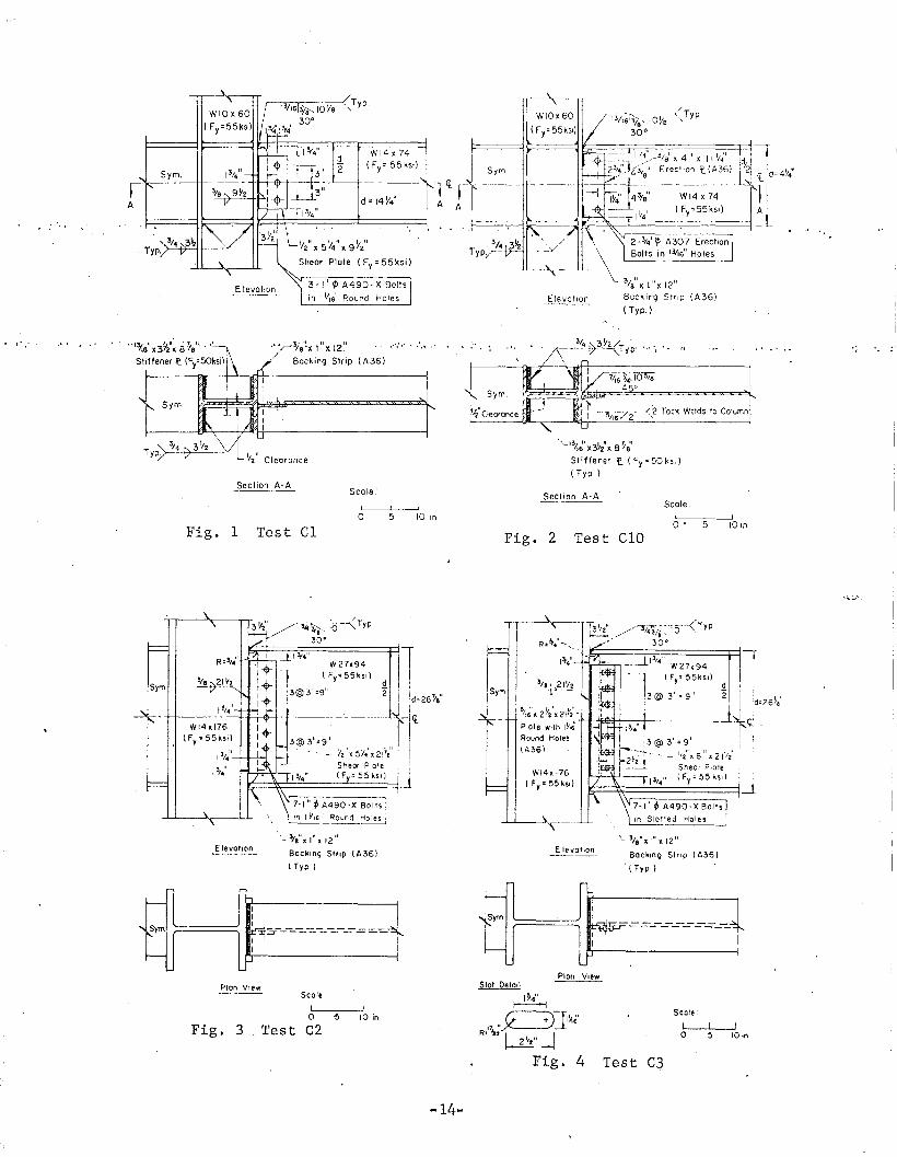
The joint detail of Test Cl is shown in Fig. 1. Beam flanges were
directly welded to the column flanges providing for plastic moment capacity.... ........ I '" 1 " j .. ... ,... : .. .. ....... ... It .. • I- ... .. .....; • '/ .. III "". ....... ..... ....._ • ....." .. 4 -4" & ..... ~ ......,~ ) ,. ... t r
A one-sided" shear plate fastened with three I in. diameter A490-X bolts was
used to resist vertical shear. The fillet weld connecting the shear plate to
the column flange was sized for vertical shear only; the moment due to the
eccentricity of the applied load was neglected. Horizontal stiffeners were
designed according to Sec. 1.15.5 of the AISC Specification. Since the con-
nection panel zone was under symmetrical loads, a clearance of ~ in. was
provided between horizontal stiffeners and column web. The size of fillet
welds for horizontal stiffeners was determined by computing the force taken
by the stiffeners when plastic moment was attained at the beam-to-column juncture.
Figure 2 shows Test CIG which is a ful1yE welded connection and was
used as a control test. Beam flanges and beam web were connected to the
column flanges by groove welds. An erection plate was tack welded to the col-
umn flange, and was used as the backing strip for the beam web groove weld.
Test C2 is shown in Fig. 3. Its connection type is similar to Test
Cl, the only di.fference being that horizontal stiffeners are not required.
Test C3 is identical with Test C2 except that the one-sided shear
plate of Test C3, shown in Fig. 4, has slotted holes. The dimensions of
~these slots conform to provisions in the current Specification (9). A con-
tinuous bar 5/16 inch in thickness and having a width equal to the length of
the slot was attached on the side of the slotted shear plate. (The addition
of continuous bars for single shear connections was approved by the Research
-6-
Council on Riveted and Bolted Structural Joints at its annual meeting on May
12, 1971).
Figure 5 shows the joint detail of Test C4. Moment capacity was
provided through direct groove welding of the beam flanges to the column
~la~ge~. Vertical s~ear was resisted by a t~o-p~ate w~14~~ ~tiffener pea~
which was designed according to Table VIII of the AISC Manual. The strength
of this connection should be greater than that of Test C5 shown in Fig. 6.
In the case of Test C5, the beam was connected to the column by
,'. .. -.,. .-. \ ........ 't.... :,.t " P~l!I t" 11II ..: \ ...~ .. ~.. ' ... ~.. - ..... II
groove welds only. It had neither an erection seat nor an erection clip.
The purpose was to determine the actual capacity of the beam flange groove
welds. '
Figure 7 shows bolted top and bottom moment plate connection Test
C6. The plastic moment was carried by flange plates which were fastened with
1 in. d~ameter A490-X bolts. The design procedure follows the example given
on page 4-92 of the AISC Manual. The bracket stiffeners were designed with
the aid of Table VIII.
Test C7 is shown in Fig. 8. The vertical shear is resisted by a ·
one-sided shear plate connected to the beam web by three 1 in. diameter A490-X
bolts. Tests Cl, C6, and C7 were designed for the same amount of moment and
shear, and, therefore, their behavior should be comparable.
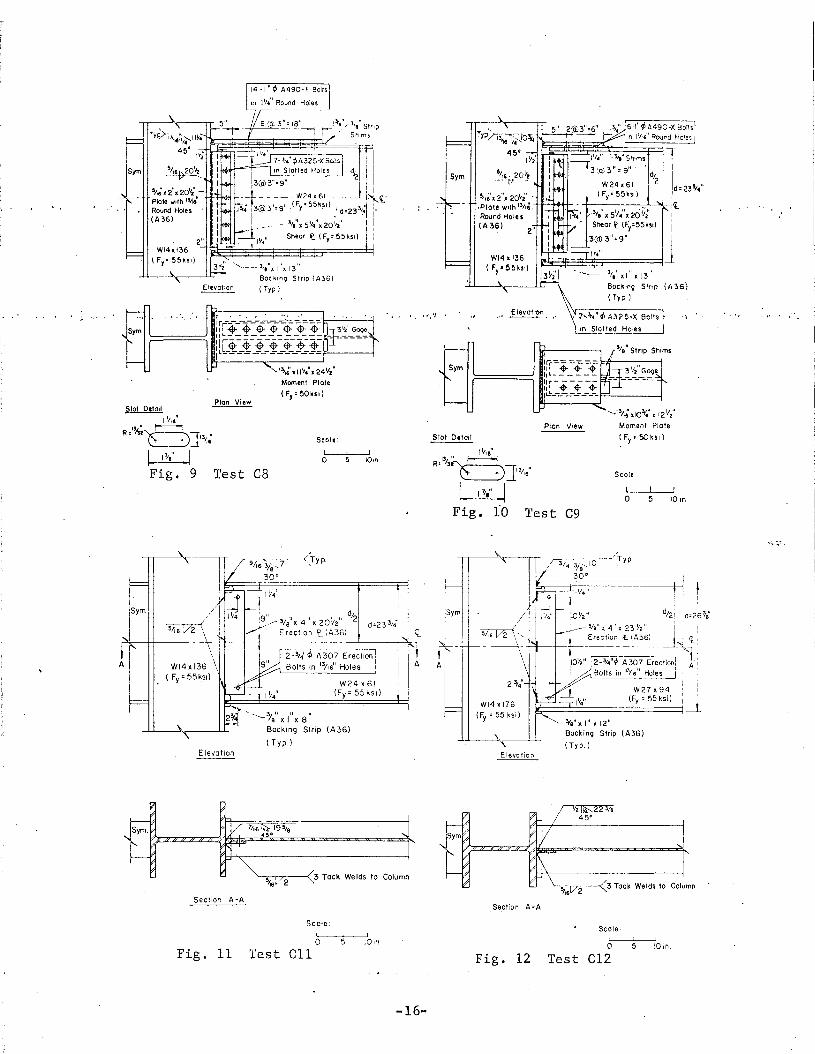
Test CS"in Fig. 9 'was designed as a friction-type connection having
oversize holes in moment plates. The use of 1-1/4 in. round holes for 1 in.
diameter A.490-F bolts is permitted by the Specification (9) . There is no re-
duction in slip resistance of the jo int. The one-sided shear plates had
slotted holes and were designed as bearing-type connections. A continuous
bar was also attached on the side of the shear plate as shown in Fig. 9.
Test C9 (Fig. 10) is similar to Test C8. For the purpose of com-
parisan, the moment plates of Test C9 were designed as bearing-type connections
having round holes 1/16 in. in excess of the nominal bolt'diameter.
-7-
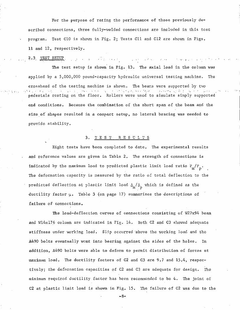
For the purpose of rating the performance of those previously de-
scribed connections, three fully-welded connections are included in this test
program. Test CIO is shown in Fig. 2; Tests CII and el2 are shown in Figs.
11 and 12, respectively.
~.3. TEST SETUP. I ..... '.' ,.
The test setup is shown in Fig. 13. The axial load in the column was
applied by a 5,000,000 pound-capacity hydraulic universal testing machine. The
crosshead of the testing machine is shown. The beams were supported by two• ~ 41 ".-. .. "1"1 ... "....... .....' ... J "".. ... • .. •'. '*;, ''/It'· + ,"y. .... III'~. .. "...../.. I ... "',.,f ~t ~ '0lil.
pedestals resting on the floor. Rollers were used to simulate simply support~d
end conditions. Because the combination of the short span of the beam and the
size of' shapes resulted in a compact setup, no lateral bracing was needed to
provide stability.
3. T EST RES U L T S
Eight tests have been completed to date. The experimental results
and reference values are given in Table 2. The strength of connections is
indicated by the maximum load to predicted plastic limit load ratio P Ip •m p
The deformation capacity is measured by the ratio of total deflection to the
predicted deflection at plastic limit load b /~ which is defined as them p
ductility factor~. T·ab1e 3 (on page 17) summarizes the descriptions of
failure of connections.
The load-deflection curves of connections consisting of W27x94 berun
and W14x176 column are indicated in Fig. 14. Both C2 and C3 showed adequate
stiffness under working load. Slip occurred 'above the working load and the
A490 bolts eventually went into bearing· against the sides of the holes. In
addition, A490 bolts were able to deform to permit distribution of forces at
maximum load. The ductility factors of C2 and C3 are 9.7 and 15.4, respec-
tively; the deformation capacities of, C2 and C3'are adequate for design. The
minimum required ductility factor has been recommended to be 4. The joint of
C2 at plastic limit load is shown in Fig. 15. The failure of C2 was due to the
-8-

tearing of the column web along the web-to-flange juncture. Figure 16 shows a1
over-all view of C2 after testing.
The unloading of C3 was initiated by local buckling of the compression
flange of the beam. The panel zone and joints of C3 after testing are shown in
'r.ig •. t7 • Th~ 1:.est;i~g o~ C~ V?'as. t~rJIl~l1at~d ,wh.en frc:.ctur~ ?~curr~d at. ~h~.. heat-
affected zone of the weld at the tension flange (Fig. 18).
C4 also exhibited'sufficient stiffness under working load. The
unloading was due to the buckling of the beam web above the stiffened seat.~ 1. • ..tl III •• .. ,a. ... , ... "", ~ ...... 'III t... '*".. ... t. ,~. JII ..
It finally failed by excessive buckling of the' beam web and fracture of the
. beam web which initiated at the cope hole as shown in Fig. 19. An over-all
view after testing is shown in Fig. 20 .•
C5 attained 51 per cent of its predicted plastic limit load based
upon whole section, and showed substantial deformation. The unloading was
due to a beam web fracture which initiated at the cope hole. Testing wasJ
terminated when the tearing of the beam web became excessive (Fig. 21) and,~',
the beam web buckled (Fig. 22).
C12 ·is afuily-weided connection. The cause for unloading was buck-
ling of the column web in the compression region. Testing was concluded due
to a combination of excessive column web deformation in the compression regi~n
and fracture at the tension flange groove weld (Fig. 23) and along the beam
web groove weld wliich occurred simultaneously. Fracture occurred by ripping
out of column flange material around weld, and not fracture of actual weld
itself. Figure 24 shows an over-all view of Cl2 after testing. A detailed
report of Test C12 is given in Ref. 11.
Tests Cl and CIO consist of W14x74 beam and WIOx60 column. Their
behavior is shown by the load-deflection curves in Fig. 25. The deviation of
Cl from CIO, that occurred above the working load, is due to slip of the joints.'
The panel zone o~ Cl at plastic limit load is shown in Fig. 26. Cl failed
when fracture occurred at the fillet weld connecting the tension stiffener to
-9-
the column flange (Fig. 27). Connection ClO after testing is shown in Fig. 28.
The compression horizontal stiffeners behaved satisfactorily; they buckled after
the attainment of the predicted plastic limit load. The failure of CIG was
also due to a fracture occurring at the fillet weld of the tension stiffener
(Fj..g •. 29) _. : ..- ..... "".,.. •• It ...
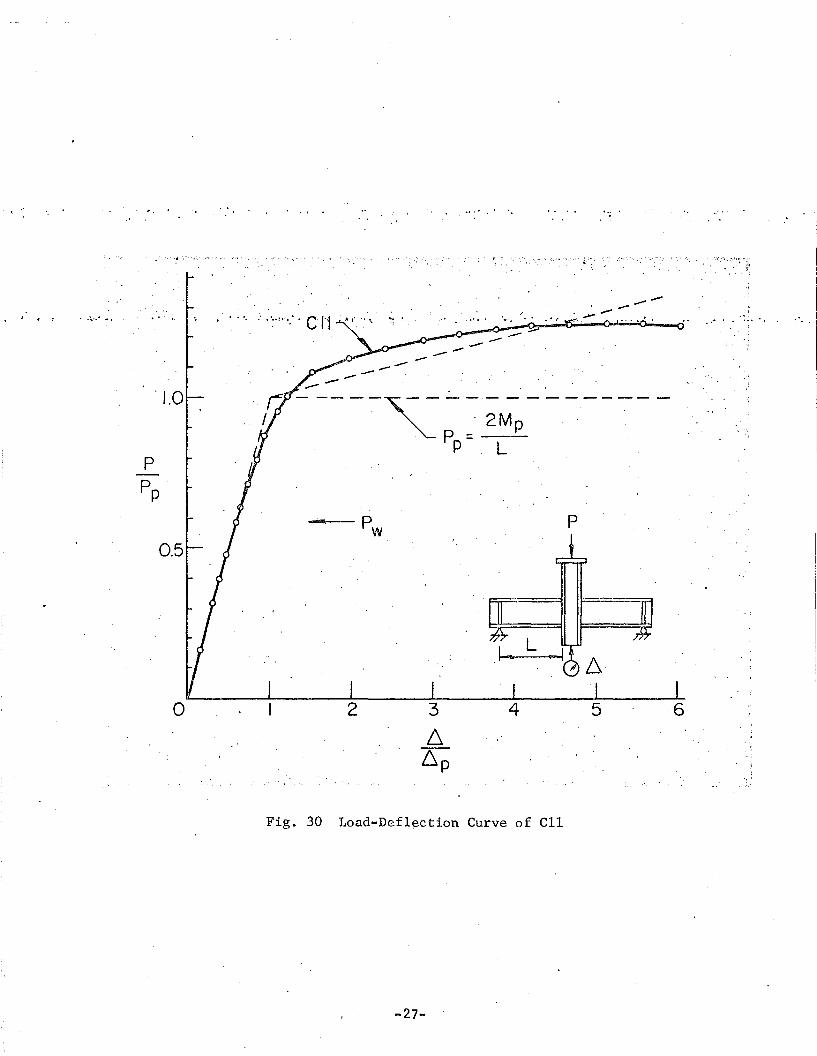
. The load-deflection curve of CII is shown in Fig. 30. This con-
nection was designed for a shear capacity' at factored load of 52.5% V whichp
simulates the loading condition in a real building. The maximum load is 25• 'II- - .." ..;'" .~ .. • • "III ,,, .. l. • ~:.. • t '\II It 4 t ..... • ... ".-."1 ... '&.IiI'lt.. .,.. if... • • til. )1" tI' ...... 't ... " jII".4.
per cent greater than the predicted plastic li~it load. This substantial in-'
crease in load-carrying capacity is attributed to the forming of plastic hinges
at the joints (Fig. 31), and therefore, strain hardening sets in quickly in
localized zones. The testing of ell was terminated when fracture occurred at
the heat-affected zone of the groove weld at the tension flange (Fig. 32).
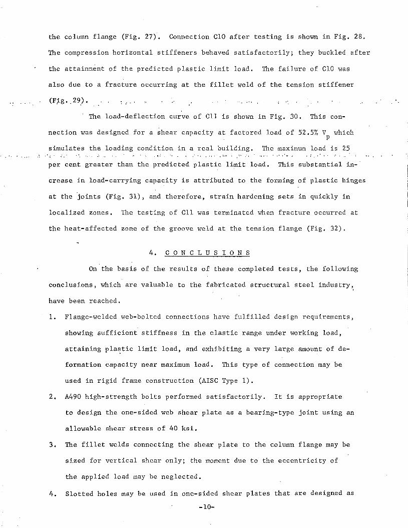
4. CON C L U S ION S
On the basis of the results of these completed tests, the following
conclusions, which are valuable to the fabricated structural steel industry~
have been reached.
1. Flange-welded web-bolted connections have fulfilled design requirements,
showing sufficient stiffness in the elastic range under working load,
attaining pla~tic limit load, and exhibiting a very large amount of de-
formation capacity near maximum load. This type of connection may be
used in rigid frame construction (AISC Type 1).
2. A490 high-strength bolts performed satisfactorily. It is appropriate
to design the one-sided web shear plate as a bearing-type joint using an
allowable shear stress of 40 ksi.
3. The fillet welds connecting the shear plate to the column flange may be
sized for vertical shear only; the moment due to the eccentricity of
the applied load may be neglected.
4. Slotted holes may be used in one-sided shear ~lates that are designed as
-10-
bearing-type joints.
~. Fillet welds may be used in lieu of groove welds in connecting horizon-
tal stiffeners to column flanges.
6. Welds approved by ultrasonic inspection were satisfactory. A careful weld
.i,nspec.tion dur:ing ,f.ab~ic~t~·o,n.was ..n~c.essary to ens~r.~ tije: ad~q~at~. pe;"~or-... • ~ •• t 'f ..
mance of connections.
5. A C K NOW LED G MEN T S
· ".' ..' . Xhe projec.t· i-s' be.ing carried au·t .at.· the ~ Fritz;· .Engineer·ing:.:Labora-
tory (L. S. Beedle, Director) as part of the research program of the Struc
tural C?nnections Division. (J. W. Fisher, Director),. The stud·y is sponsored
jointly by the American Iron and Steel Institute and the Welding Research
Council. Research work is carried out under the technical advice of the WRC
Task Group, of which Mr. J. A. Gilligan is Chairman.
The authors are especially grateful to Messrs. J. A. Gilligan, o.
W. Blodgett, ·C. F. Diefenderfer, W. E. Edwards and C. L. Kreidler for their
valuable suggestions and assistance in the fabrication of the specimens.
Thanks are also due Messrs. J. E. Regec, K; R. Harpel and the technicians of
Operations Division for their help in testing, and to Mr. R. Sopko for the
photography. The manuscript was reviewed by Dr. G. C. Driscoll, Jr. and
typed by Miss S. Matlock. The drawings were prepared by Mr. J. Gera. Their
help is appreciated.
-11-

TABLE 1 TEST PROGRAM OF C-SERIES CONNECTIONS
Test(1)
Beam ColumnSize Size
(2) (3)Moment
(4)
Factored LoadShear
(5)
Cl W14x74 W10x60 M' =69301<'- inBgam flangegroove weld
V=161K(88.5%V· )Shear plate, 3El 't q5A490-Xin 1-1/16"
round holes
3 1 -7"
cz', W27x94 W14x176' M =15290K-inB~am flangegroove weld
v=3·74K(94.7%V ) 3' -5"Shear plate, P7-1"s6A490-X in1-1/16" rnd. holes
: t 10
C3 W27x94 w14x176 DO
oR I. ~... .. I .. ,,~ + ...
DOShear plate has:8 io t t'ed· ho res .
3 1_5"
...~ • 11I'. ~. JI ... .. • ,. t
c4
C5
C6
W27x94 W14x176 DO
W27x94 W14x176 Beam flangegroove weld
W14x74 WIOx60 M =6930K-inMgment plates8-1"sOA490-Xin1-1/16F1 roundholes
V=374K(94.7%V )Two-plate welHedstiffened seat
Beam flangegroove weld
V=161K(88.5%V )Stiffener pla~e1"xS"xl1 11
3' - 5"
3 ' - 5"
C7 W14x74 WlOx60 DO .V=161K(88.5%V·} 3'-7"Shear plate, P3-1t1~A490-X in1-1/16" rnd. holes
,~.
C8 W24x61 W14x136 M =8360K-in V=157.5K(52.5%V)Mgment plates Shear plate, P14-l11 0A490-Fin 7-3/4"r/>A325-X inI-114ft round slotted holesholes
4' -5"
C9 W24x61 W14x136 M =8360 K-inMgment plates6-1"r/>A490-Xin1-1/16" roundholes
CIO W14x74 WIOx60 M =6930 K-inB~am flangegroove weld
ell w24x61 W14x136 M =8360K-inB~am flangegroove weld
Cl2 W27x94 W14x176 M =15290K-inB~am flangegroove weld
DO
V=161K(88.5%V )Beam web ,p
groove weld
V=157.5K(52.5%V)Beam web Pgroove weld
V=374K(94~7%V )Beam web Pgroove weld
.3'-7"
4'-5"
3,1_5"
a. All.specimens were made of ASTM A572 Grade 55 steel.c=2lfha
b. ha for all specimens is 2' -6". hb is l' -3" .." n IL.i.hb
---- ---- -- -12- 1-f1-L.it

,,," 'III .,. ~ • .., .. 4" ., 'f ," .... .II 11:.
TABLE 2 TEST RESULTS
.TestExperi-
.', Reference.' ment'al . . . .. ... •11 • t . , : P' p . p' .' . '!:i'm --ill... m ......!!!-
P 6 P P P ~ P P P ~m m p ps pr p p ps pr p
(1) (2) (3) (4) (5) (6) (7) (8) (9) (10) (11)
Cl 357.5 1.50 322 286 271 0.361 1.11 1.25 1.32 4.2
... "....... ., .. . . . ~ ~ .. • t 'II oiII ~ ... .. " '
C2 826 2.67 748 590 522 .0.276 1.10 1.40 1.58 9.7
C3 818 4.26' 748 590 522 0.276 1.09 1.39 1.57 15.4
C4 660 0.57 748 590 522 0.276 0.88 1.12 1.26 2.1
C5 380 1.72 748 370 522 --- 0.51 1.03 0.13 --
CIO 364.5 1.57 322 286 271 0.361 1.13 1.27 1.34 4.4
Cll 392.5 2.05 315 266 199 0.341 1.25 1.47 1.97 6.0
el2 838 3.63 74,8 590 522 0.276 1.12 1.42 1.61 13.2
a. All loads (P) listed are column loads in kips; all deflections(~).are in inches.
-13.-,
" .
~ ; • • ..l
A
Sym.--++--
Typ.
Elevation
WI4 x.. 74(Fy= 55ksd
'.v2
uX 5¥4
11)( 9¥ZIl
Shear Plate (Fy :: 55 ksi)
3 ~ 111 <P A490- X Bolts
in I Viet! Round Holes
l<tA A
Sym
2 _3/41 tp A30 7 Erection
\ Bolts in 13/16" Holes
3/8" x tllx 12 11
Elevation Bocking Strip (A36)
(Typ. )
. .' '·r~611X3Y2·~ 8'leu•.
Stiffener ft (Fy=50ksil
Sym.
3/e'~x I"x 12~1 "':,' ':.• "
Backing Strip (A36)
Sym.
IJi Clearance
'--13/1~' X3~2' X 8 'le"St iHener re. (Fy :: 50 ksj)(Typ )
-:. ..
Fig. 1 Test Cl
Section A-AScale:
, I
o 5 10 in_Scale.
, 1
0 1 5
Fig. 2 Test CIO10 In.
,~'-
R':~4"--'.,
J~4"----'-""\- J"----' _
WI41t176( Fy :: 55 kSI)
&/l~' X 2Y2"X 2I Y;'Plate Wllh 1\1
16' +-II-..lE--~+----1~- • ---------
Round Holes(A36)
3 Y2" //~~.lo--<TYP30°
WI41t176(Fy :55ksil
13/",11
13/4u
ElevatIOn'. - 3/8" X l" II 12 01
Backing Stnp (A36)
(Typ)
E levotton\- 3/," II I" x 12"
Backing Strip (A36)
(Typ)
Pion View
Scole-
oFig. 3 . Test C2
-5 10 in
Slot Detoll
~~tl~6'
11 "X----JJ'R' ~ I ~I,._ I. ~"-~
Fig. 4 Test C~
Scole:
lo 5 10 In
-14-

lain
I!
!~~
i· .!!
o 5
Scale:
I I
W27 x 94( Fy ::55kSi)
~ 3/ell
x I"x 12 ff
Backmg StriP (A36J
(Typ.)
Test C5
Pion View
E levotion..~
Wl4 x.~76 •(Fy ::55ksi)
Fig. 6
Sym.
a
te
Side View
Test C4
\ + t i
1--=---=--=--1- j= =-=--=t -- - - --1'
I I " Scale:I 1
Fig. 5
\.
j3~IO-<TYP,
/ 30° J==~ ....... ~-_3/e"x I"x 12 11
BocklOg StriP
3/e" Setback~ r- I---(A36)
...... r-. .......~
Sym W27x 94
W 1'4 x t76: ( Fy'; 55 ksl)
( Fy ::55kSl)
')~ -<" ;T
~~/7
IY4"x9tlx 12"',,-------
51l~ Seat Plate--- .....(A36)
'. ., .. 51;;,'. .~
~~~~-~." '.
. _1 1/4" X 9" x 19
Stiffener PIa
\.(A36),
A
5/1G ,. 4• I ~ .-
~ I~e" x 10"x 15;e"
Moment Plate(Fy :: 55ksil
'\
Sym,
A
-----lye" x 10"x 15~B"
Moment Plate
3_1 11 ¢ A490-X Bolts (Fy :: 55 ksl)
in l!lls" Round Holes
r 3/811
X jllx Ii'-1tiffener r(Fy:55ksl)
,..i,Backing Stnp (A36)
112~ Clearcnce t .-++ -+-:t5 1/211
GageIt--..
...... 1')...• '- • + t- .:-1Sym.
Jh I I
III X 4 1ll( .a 7/el'
s
a_Ill ¢ A490-X Bolts
in I 'fIG" Round Holes
3/ell x.1 tl x 12 11
Backing StriP (A36)
B -.J '-, '.~ Sf if fener Pia te
lUx SIlX IIIl (A36)
Section A-A
Sym.
y,; Clearance
Section A-A
Fig. 7
Scole:
I Io 5
Test C6lOin.·
Fig. 8 Test C7
Scale
I Io 5
-15-
5o
Seole:
·........."1.: .lK)~. x 121/2
11
Moment Plate
(Fy =50kSI)
Pion View
Sym
Slot Detail
III,," UIa~Shlms 11 3 :0)3"'=901 I
d/2
!d,23'1"W24.61
!/16' x 2"x 2o~i' . (FyE 55ksd
,Plote with 13/1&,.)/.')( 51/,,",; 26 j;~'
·i~Round Holes I 4 I
(A36) J Sheor ~ lFy'55k>l) i3(0) 3 11 :9" 1I~,,"
·~__ 3/."xl x 13BackJn9 Strip (A36)
(Typ)
••~ III- tt. Elevation ':T~~"~ A325.X 8<llt.I .. ~.,._~~.
~_~)~t~~~les
Scote:
I I
o 5
l3'/~' X II Y,,- X 24Y2"
Moment Plate
(Fy =50ksi)
Test C8
3Y~ "'--- -~ 3/,"X I "X 13"
BOCklnQ Strip (A36)
Elevotion ( Typ )
Sym.
Sial Detoll
1'I'e"I!L"- ,r----tR;IU~]13"~ ~.
I .1J_", I~Fig. 9
Elevation
W24x61(Fy ;: 55 kSI)
~?Y8~X III x 12 11
Backing Strip (A36)
(Typ. )
W27 x94
ir';:===~=========(F=y===5=5=kS=il==11 ----L
Elevation
WI4 x 176(Fy :: 55 ksi)
2.3/4' tP A307 ErectionBolts in 13/16
11 Holes
<I d;.:9 ...-- 3/8
11X 4 It X 20h II 2
Erection FL (A36)
.................... 3;811
X In x 8"
Bocking Strip {A36}
( Typ.)
1"r-~~f5!;~
Sym. ~~z:::;;~::zzif)~4;::rc=:~4 ~::s0:c:::s,'!~:=:SS:~::::S:S;==::S:S~:::::;:S;;::::S::S::;:::::S::S::::S:S:::i'-
~~1J6-"-?""""2-----«3 Tack Welds to Column
Section A-A
~...............---.. 3 Tack Welds to Column
Section A~A
Fig. 11'
Scale:
oTest CII
5 10m
Fig. 12
Scole;
oTest el2
'~ lOin.
-16-
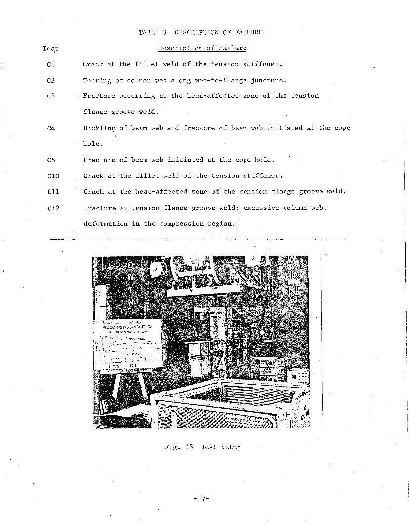
TABLE 3 DESCRIPT"ION ,OF FAILURE
C3
C2
Cl
C4
Description of Failure
Crack at the fillet weld of the tension stiffener.
Tearing of column web along web-to~flange juncture.
Fracture occurring at th~heat-affected zone of the tension
flange,groove weld.
Buckling of beam web and fracture of beam web initiated at the cope
hole.
C5 Fracture of beam web initiated at the cope hole.
Test
CIO Crack at the fillet' weld of the tension stiffener.
ell Crack at the heat-affected zone of the tension flange groove weld.
C12 Fracture at tension flange groove weld; excessive coluffiIt web ..
deformation in the compression region.
Fig. "13 Test Setup

.......-ppr
.... .... ,. ... '"" ....
15
t ~ f,. •
-p
10
-- --~-- - ------.--C3 ., ' 2Mp
. Pp = -L-
5
/.. ,:t. / .. : .... :.. .' .,.
/'/C2
f---IIIII "
o
0.5
.1.0
;,
-t • ... .. ... '" ~ • l1li ..." ~ .... ."'"
."'.' '-t,-
Fig. 14 Load-Deflection Curves of Connections C2, C3, C4, C5 and C12
-18-
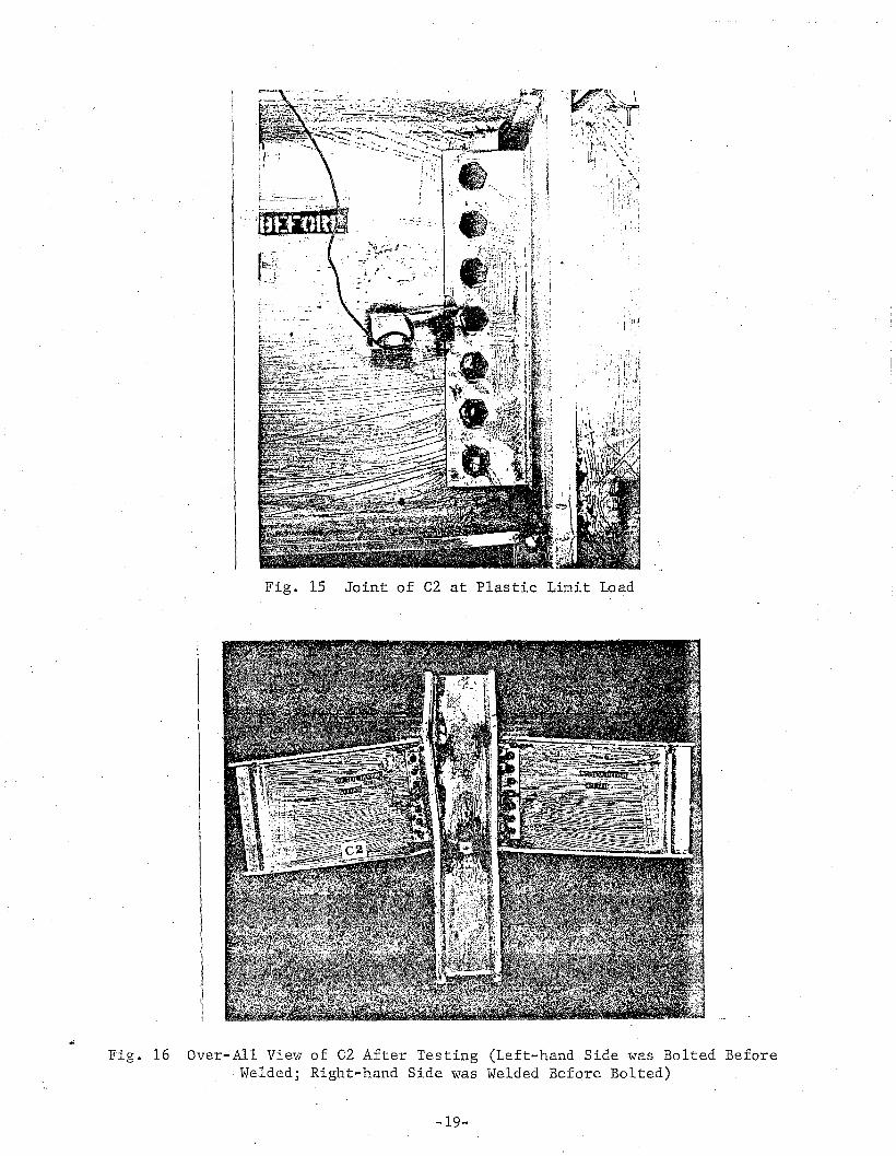
Fig. 15 Joint of C2 at Plastic Limit Load
Fig. 16 Over-All View of C2 After Testing (Left-hand Side was Bolted BeforeWelded; Right-hand Side was Welded Before Bolted)
-19-
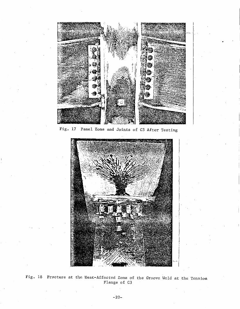
Fig. 17 Panel Zone and Joints of C3 After Testing
Fig. 18 Fracture at the Heat-Affected Zone of the Groove Weld at the TensionFlange of C3
-20-

Fig. 19 Buckling of Beam Web and Tearing of Beam Web at Cop~ Hole of C4
Fig. 20 Over-All View of C4 After Testing
-21-
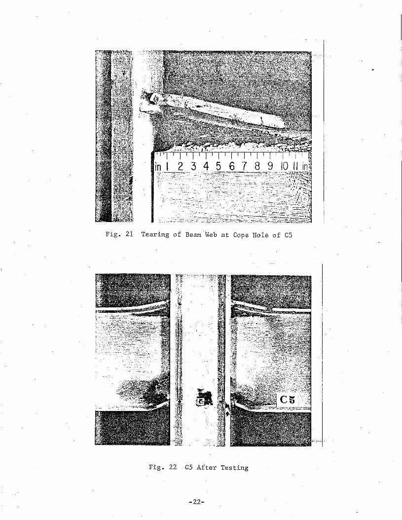
Fig. 21 Tearing of Beam ·'Web at Cope Hole of C5
Fig. 22 C5 After Testing
-22-
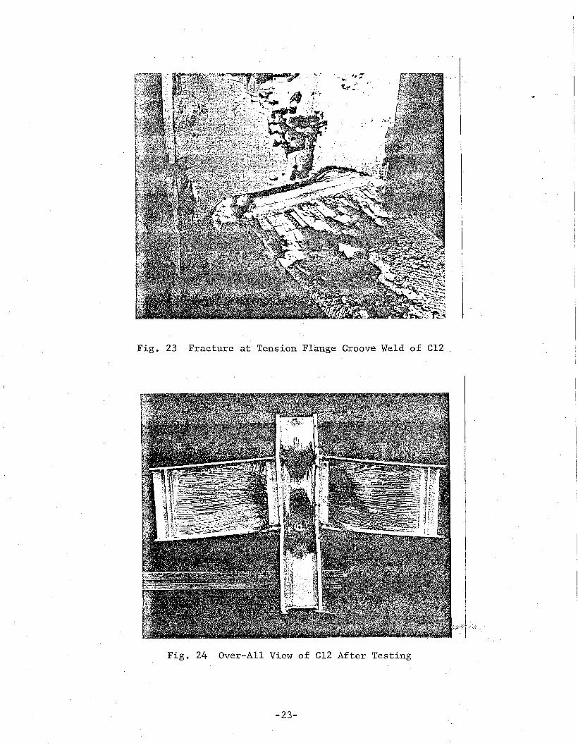
Fig. 23 Fracture at Tension"Flange Groove Weld of el2
Fig. 24 Over-All View of el2 After Testing
-23-

1ft • III 11-.... • ... 1(11 .. .. t .... " ... I ~ .'...
-1.0
p
p~
0.5
a
. '." " .. ' " .' " o'C·IG ~_ t·
-- ,----- .........,.-- ~---.
r -:;::.-=--- -/
/h
..
LJ-. -~
3
.. .......~ .. .. " .. ..' ~ .. .. ,.......... .
p
-4
Fig. 25 Load-Deflection Curves.of Cl and CIO
-24-
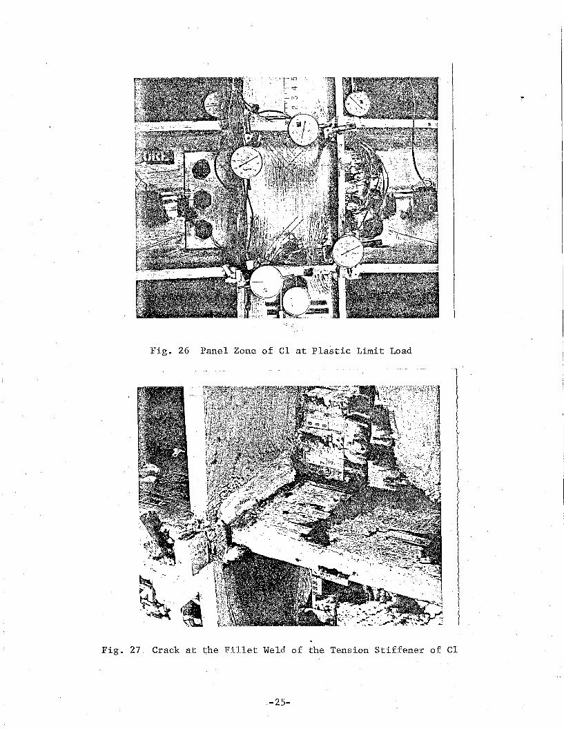
Fig. 26 Panel Zone of Cl at'Plastic Limit Load
Fig~ 27. Crack at the Fillet Weld of the Tension Stiffener of Cl
.-25-
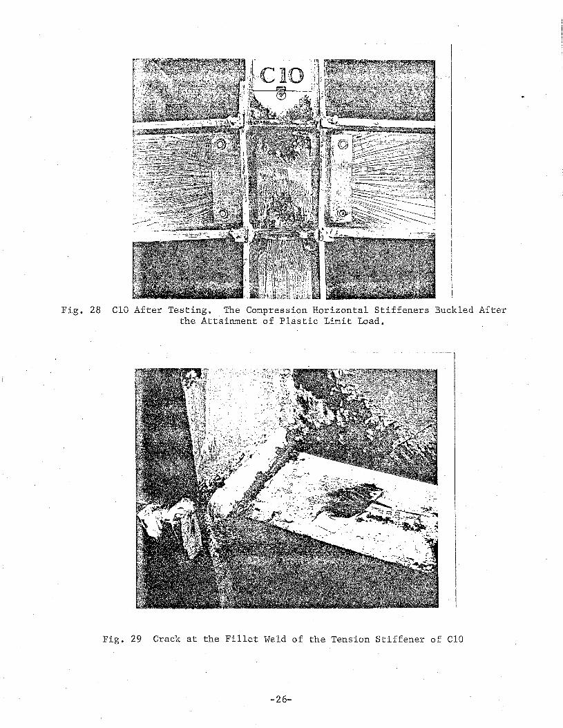
Fig. 28 CIO After Buckled After
.
Fig. 29 Crack at the Fillet Weld of the Tension Stiffener of CIO
-26-
.. It.,.......... • ......- --
I .... h
"1.0
0.5
o
I... L-I. - 6
2 3 4 5 -6
66 p
Fig. 30 Load-Deflection Curve of Cll
-27-
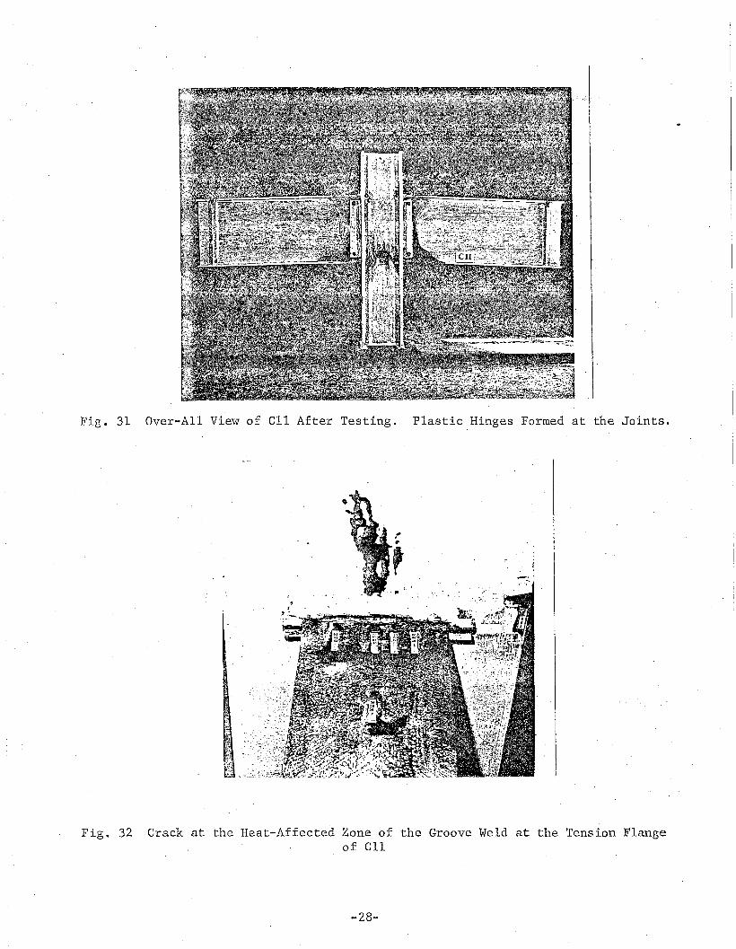
Fig. 31 Over-All View of ell After Testing. Plastic Hinges Formed at the Joints.
~r,
Fig. 32 Crack at the Heat-Affected Zone of the Groove Weld at the Tension Flangeof ell
-28-

APPENDIX I - ·REFERENCES
1. AISCMANUAL OF STEEL CONSTRUCTION, 'SPECIFICATION FOR THE DESIGN, FABRICA
TION AND ERECTION OF STRUCTURAL STEEL FOR BUILDINGS, 7th ed.,American Institute of Steel Construction, 1970.
2. Allan, R. N. and Fisher, J. W.BOLTED JOlNTS WITH OVERSIZE 9R SLOTT.ED .HOLES ,. Journal, ,of. the Str.uc
tural Divisio'n,' ASeE, 'Vol" 94, No. ST9, Proe; Paper 6113~ 'September 1968, p. 2061.
..... ...~,t
, .
3. AWSCODE FOR WELDING IN BUILDING CONSTRUCTION, AWS Dl.O-69, 9th ed.,
American Welding Society, 1969... • -10 .... r~. .. ....... I of .... ~ .. f1'" ,.1 '" .. "t~
4. Beedle, L. S. and Christopher, R.TESTS OF STEEL MOMENT CONNECTIONS, AISC Engineering Journal, Vol. 1,
No.4, October 1964, p. 116.
5 •. Fisher, J. W. and Beedle, L. S.CRITERIA FOR DESIGNING BEARING-TYPE BOLTED JOINTS, Journal of the
Structural Division, ASeE, Vol. 91, No. ST5, Prac. Paper 4511,October 1965, p. 129.
6. Huang, J. S., Chen, W. F. and Regec, J. E.TEST PROGRAM OF STEEL BEAM-TO-COLUMN CONNECTIONS, Fritz Laboratory
Report 333.15, Lehigh Universi~y, Bethlehem, Pa., July 1971.
7. Kulak, G. L. and Fisher, J. W.AS14 STEEL JOINTS FASTENED BY A490 BOLTS, Journal of the Structural
Division, ASCE, Vol. 94, No. STIO, Proc. Paper 6163, October 1968,p. 2303.
8. Popov, E. P. and Stephen, R. M.CYCLIC LOADING OF>-FULL-,SIZE·.,"gTEEI2.~s,CON}JECTEfaNS, Earthquake Engineering
Research Center Report 70-3, University of California, Berkeley,California, July 1970. Also, AlSI Bulletin 21, February 1972.
9. RCRBSJSPECIFICATION FOR STRUCTURAL JOINTS USING ASTM A325 OR A490 BOLTS,
7th ed., Research Council on Riveted and Bolted Structural Jointsof the Engineering Foundation, March 1970.
10. Regec, J. ~., Huang, J. S. and Chen, W. F.MECHANICAL PROPERTIES OF C-SERIES CONNECTIONS, Fritz Laboratory Report
333.17, Lehigh University, Bethlehem, Fa., April 1972.
11. Regec, J. E., Huang, J. S. and Chen, W. F.TEST OF A FULLY-WELDED BEAM-TO-COLUMN CONNECTION, Fritz Laboratory
Report 333.21, Lehigh University, Bethlehem, Fa., September 1972.
12. Sterling, G. H. and Fisher, J. W.A440 STEEL JOINTS CONNECTED BY A490 BOLTS, Journal of the Structural
Division, ASCE, Vol. 92, No. ST3, Proc. Paper 4845, June 1966,p. 101.
-29-

APPENDIX II - NOTATION
The following symbols are used in this paper:
maximum deflection;
= deflection;
= beam. span;
factor, ~ d 6 /6 •m p
= deflection -at plastic limit load~ and
= ductility
= plastic limit load modified to include the effect of shear force,assuming the area of beam web is zero;
working load, P == P /1.7·w p ,
= shear force;
= shear force that produces full yielding of web;
= maximum load of a connection under test;
= plastic limit load;
= plastic limit load assuming the area of beam web is zero;~ : : . • r· .-: :-~ ...... \:"'Ii -"'''? ..-t ,. .' ....
plastic limit load modified to include the effect of shear force;
= .applie~ column load~
= plastic moment;
L
MP
.'p
pm
pp
p"
._p~ .p
ps
p1ps
Pw
V
VP
6-
6m
bp
~

![SHIVAJI U IVERSITY, KOLHAPUR-416004, …Estd.1962 AAC ‘A’ Grade MHRD- IRF – 28 th Rank SHIVAJI U IVERSITY, KOLHAPUR-416004, MAHARASHTRA f'kokth fo|kihB] dksYgkiwj&416004 egkjk"Vª](https://img.dokumen.tips/doc/110x75/5f0280137e708231d4049206/shivaji-u-iversity-kolhapur-416004-estd1962-aac-aaa-grade-mhrd-irf-a-28.jpg)


![SHIVAJI U IVERSITY, KOLHAPUR-416004, MAHARASHTRA … Date of... · Estd.1962 AAC ‘A’ Grade SHIVAJI U IVERSITY, KOLHAPUR-416004, MAHARASHTRA f'kokth fo|kihB] dksYgkiwj&416004 egkjk"Vª](https://img.dokumen.tips/doc/110x75/5c93295809d3f21a398bb18d/shivaji-u-iversity-kolhapur-416004-maharashtra-date-of-estd1962-aac-a.jpg)