Embed Size (px)
Citation preview

PHYSICAL REVIEW A 90, 063807 (2014)
Left-handed electromagnetic waves in materials with induced polarization and magnetization
D. D. Yavuz and N. R. BrewerDepartment of Physics, 1150 University Avenue, University of Wisconsin at Madison, Madison, Wisconsin, 53706, USA
(Received 27 June 2014; revised manuscript received 30 October 2014; published 5 December 2014)
We analyze the properties of electromagnetic waves inside materials with induced polarization andmagnetization. We show that if the polarization and magnetization of the material are sufficiently large andappropriately phased, then the system supports the formation of left-handed waves. In some respects, such asystem behaves similarly to materials with a negative index of refraction, yet there is one important advantage:Left-handed waves in materials with induced polarization and magnetization do not require as stringent materialproperties (such as the strength of resonances and the density of radiators). We numerically investigate theformation and propagation of such left-handed waves using finite-difference approximation to Maxwell’sequations. We also discuss possible experimental observation of these ideas in a rare-earth-doped crystal.
DOI: 10.1103/PhysRevA.90.063807 PACS number(s): 42.70.−a, 78.20.Ci, 42.65.An, 81.05.Xj
I. INTRODUCTION
Over the past decade, the interest in left-handed electro-magnetic waves where E, H , and k vectors form a left-handedtriad has been continuously growing. The most well-knownexample of materials that support left-handed waves arenegative-index materials. These materials were first predictedby Veselago, who argued that materials with a simultaneouslynegative permittivity and permeability would exhibit a negativerefractive index (throughout this paper the term negativerefractive index is reserved for materials in the sense exactlydescribed by Veselago) [1]. Although the interest in negativeindex remained a scientific curiosity for a long time, it isnow understood that these materials may have importantapplications such as constructing lenses that beat the diffrac-tion limit [2–4] and engineering electromagnetic cloaks [5,6].Two different (and somewhat complementary) approaches arecurrently being pursued to construct negative-index materials:(i) metamaterials [7–16] and (ii) atomic systems [17–23]. Neg-ative refraction has so far been experimentally demonstratedin both the microwave [7–10] and the optical [11–16] regionsof the spectrum, with all experiments thus far relying on meta-materials. The second approach uses sharp electric-dipole andmagnetic-dipole transitions of atoms to modify the permittivityand permeability appropriately to achieve a negative refractiveindex. In the spirit of electromagnetically induced transparency(EIT) and related techniques [24,25], the idea is to dress theatomic system with strong lasers in such a way to produce anegative refractive index for a weak probe beam.
Constructing negative-index materials has so far beenchallenging due to a number of difficulties: (i) The permittivityand permeability have to be simultaneously modified, and asa result, one needs both electric and magnetic resonances nearthe same wavelength. (ii) The electric and magnetic resonancesof the system have to be strong, which translates into stringentrequirements on the number of radiators required. In atomicsystems, all suggested schemes require atomic densities inexcess of 1016 atoms/cm3 [17–23]. In many experimental sys-tems it is simply not possible to achieve such high densities andsimultaneously preserve sharp atomic transitions (linewidthsat the level of 1 MHz are required). (iii) An ensemble ofradiators that satisfies these first two requirements typicallyproduces large absorption [26]. This is particularly pronounced
in the optical domain where the imaginary part of the refractiveindex is typically almost as large as the real part. This isa key limitation for many potential applications since lightis largely absorbed within a few wavelengths of propagationinside the material. There has been some recent progress onovercoming absorption using active metamaterials [27]. Inatomic systems, absorption can, in principle, be overcomeusing quantum interference ideas such as EIT or the inter-ference of two Raman transitions [19,21]. Nevertheless, thesedifficulties that are outlined in this paragraph are formidablefor many experimental implementations of negative index.Due to these difficulties, negative index in atomic systems hasnot yet been experimentally observed. Furthermore, althoughthere have been many exciting experimental results from themetamaterial community, the performances of the constructednegative-index materials are still far from what is needed forpractical applications. For example, it is still not clear if it willbe possible to construct widely applicable super-resolutionoptical microscopes using negative-index materials.
We therefore feel strongly that it is important to investigatealternative ideas that exhibit some of the physics and appli-cations of negative-refractive-index materials. In this paper,we study the propagation of electromagnetic waves insidea material where the medium is polarized and magnetizedexternally (i.e., through means other than the incident electro-magnetic wave). We argue that if the induced polarization andmagnetization are sufficiently large and appropriately phased,then the medium will support the formation of left-handedwaves. Such materials appear to manifest much of the physicsof negative-index materials. Compared to materials with anegative refractive index, there is one clear advantage ofmaterials with induced polarization and magnetization: Theformation of left-handed waves does not require the stringentmaterial properties (such as the strength of the resonances, thedensity of radiators, and so on). As a result, the ideas presentedin this paper may result in (1) an observation of left-handedwaves in atomic systems and (2) more practical and flexiblemetamaterials for left-handed wave studies.
II. FORMALISM AND ANALYTICAL RESULTS
We begin our discussion by rewriting Maxwell’sequations inside a polarized and magnetized
1050-2947/2014/90(6)/063807(9) 063807-1 ©2014 American Physical Society
D. D. YAVUZ AND N. R. BREWER PHYSICAL REVIEW A 90, 063807 (2014)
material:
∇ × �E = −∂ �B∂t
,
∇ × �H = ∂ �D∂t
,
(1)∇ · �D = 0,
∇ · �B = 0,
where the displacement vector �D and the magnetic field �B aremodified inside a material to include the polarization ( �P) andthe magnetization ( �M):
�D = ε0 �E + �P,(2)�B = μ0 �H + μ0 �M.
The medium can be polarized and magnetized at a specificfrequency ω using a number of processes. The most obviousone would be if the frequency of the incident electromagneticwave is close to an electric-dipole (or a magnetic-dipole)resonance, then the incident wave itself can polarize (or mag-netize) the medium through the linear response of the material.Physically, macroscopic polarization can be visualized as anensemble of microscopic electric dipoles oscillating in unison.Similarly, macroscopic magnetization can be visualized as anensemble of magnetic dipoles (current loops) oriented along acommon direction. It is important to note that the medium canalso be polarized or magnetized at a frequency ω using externalmeans (i.e., processes that do not depend on the incidentelectromagnetic wave). Throughout this paper, we focus onexternally induced polarization and magnetization. This canbe accomplished, for example, by applying powerful lasersat other frequencies and using the nonlinear response of thematerial. We discuss a specific scheme later in this paper.
Using Eq. (2), the first two of the Maxwell’s equationsinside a material can be reduced to
∇ × �E = −μ0∂ �H∂t
− μ0∂ �M∂t
,
(3)
∇ × �H = ε0∂ �E∂t
+ ∂ �P∂t
.
We now look for plane wave solutions of Eq. (3). Weassume that the medium is polarized and magnetized atthe same frequency ω with exactly the same k vector andtake �P = �P exp (i�k · �r − iωt) and �M = �M exp (i�k · �r − iωt).With the assumed polarization and magnetization, we look forforced-wave solutions for the fields, �E = �E exp (i�k · �r − iωt)and �H = �H exp (i�k · �r − iωt). With plane waves, Maxwell’sequations reduce to
�k × �E = μ0ω( �H + �M),(4)�k × �H = −ω(ε0 �E + �P ).
From Eq. (4), we see that if the �E and �H vectors are chosento be of appropriate magnitude and π out of phase with theinduced polarization and magnetization, there would be signflips on the right-hand side of the equations. A particularlyinteresting case, which we focus on in the remainder ofthis paper, is if the field quantities are chosen such that
EM
H
P
k
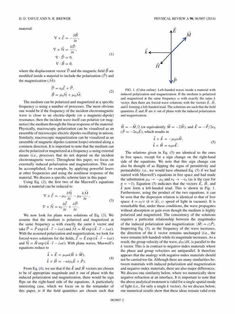
FIG. 1. (Color online) Left-handed waves inside a material withinduced polarization and magnetization. If the medium is polarizedand magnetized at the same frequency ω with exactly the same k
vector, then there are forced-wave solutions with the vectors �E, �H ,and �k forming a left-handed triad. The solutions are such that the fieldquantities �E and �H are π out of phase with the induced polarizationand magnetization.
�H = − �M/2 (or equivalently �M = −2 �H ), and �E = − �P/2ε0
( �P = −2ε0 �E), which results in
�k × �E = −μ0ω �H,(5)�k × �H = ε0ω �E.
The relations given in Eq. (5) are identical to the onesin free space, except for a sign change on the right-handside of the equations. We note that this sign change canalso be thought of as flipping the signs of permittivity andpermeability; i.e., we would have obtained Eq. (5) if we hadstarted with Maxwell’s equations in free space and had madethe substitution μ0 → −μ0 and ε0 → −ε0 (as is the case forn = −1). Equation (5) indicates that the vectors �E, �H , and�k now form a left-handed triad. This is shown in Fig. 1.Furthermore, using the product of the two equations, it canbe seen that the dispersion relation is identical to that of freespace: k = ω/c (k ≡ |�k|, c: speed of light in vacuum). It isremarkable that, under these conditions, the wave propagateswithout absorption or gain even though the medium is highlypolarized and magnetized. The consistency of the solutionsrequires a particular relationship between the magnitudesof the induced polarization and magnetization: | �M| = c| �P |.Inspecting Eq. (5), as the frequency of the wave increases,the direction of the k vector remains unchanged (i.e., thewave remains left-handed) while its magnitude increases. As aresult, the group velocity of the wave, dω/dk, is parallel to thek vector. This is in contrast to negative-index materials wherethe phase and group velocities are antiparallel. It thereforeappears that the analogy with negative-index materials shouldnot be carried too far. Although there are many similarities be-tween materials with induced polarization and magnetizationand negative-index materials, there are also major differences.We discuss one similarity below, where we numerically shownegative refraction at an interface. It is important to note thatthe above analytical treatment is valid for a single-spatial modeof light (i.e., for only a single k vector). As we discuss below,our numerical results show that these ideas remain valid even
063807-2
LEFT-HANDED ELECTROMAGNETIC WAVES IN . . . PHYSICAL REVIEW A 90, 063807 (2014)
k2
E2
H2
E1
H1k1
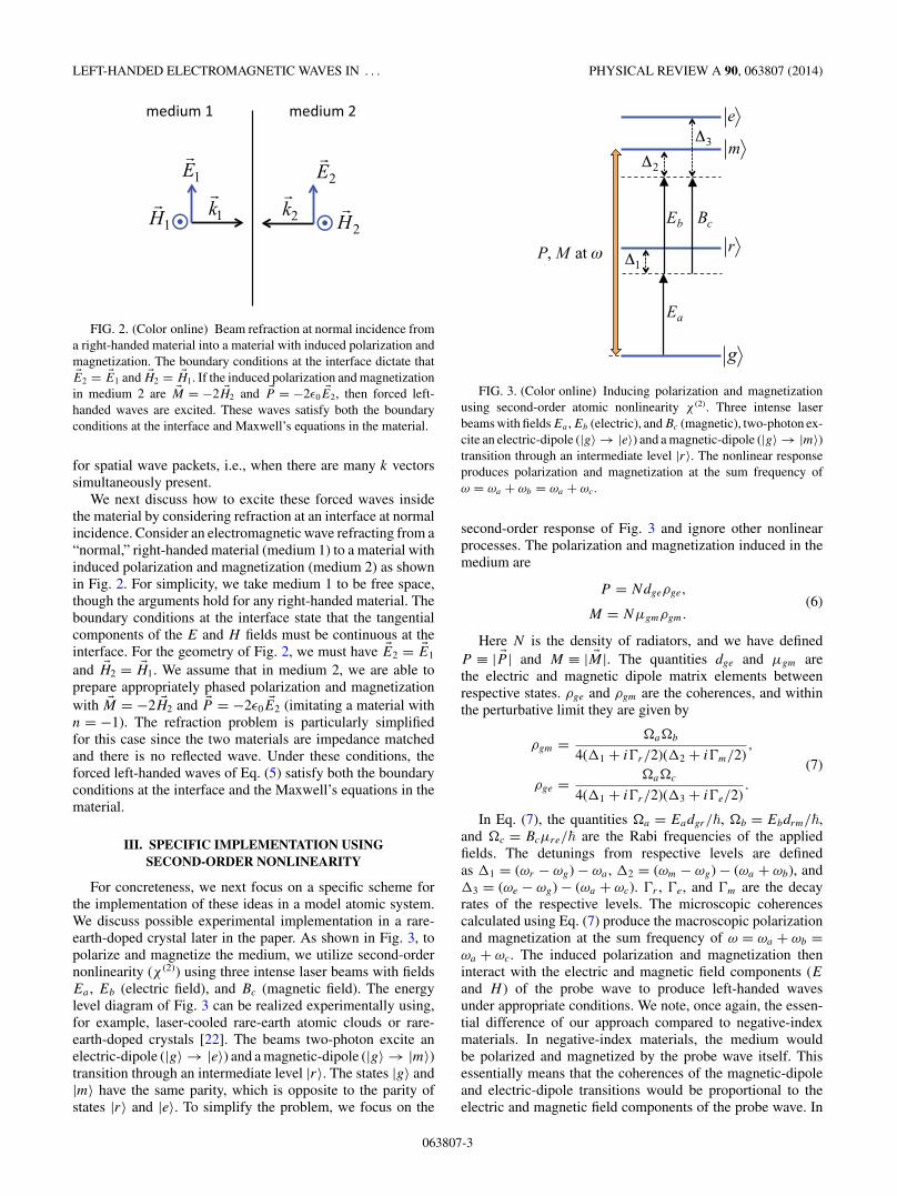
FIG. 2. (Color online) Beam refraction at normal incidence froma right-handed material into a material with induced polarization andmagnetization. The boundary conditions at the interface dictate that�E2 = �E1 and �H2 = �H1. If the induced polarization and magnetizationin medium 2 are �M = −2 �H2 and �P = −2ε0 �E2, then forced left-handed waves are excited. These waves satisfy both the boundaryconditions at the interface and Maxwell’s equations in the material.
for spatial wave packets, i.e., when there are many k vectorssimultaneously present.
We next discuss how to excite these forced waves insidethe material by considering refraction at an interface at normalincidence. Consider an electromagnetic wave refracting from a“normal,” right-handed material (medium 1) to a material withinduced polarization and magnetization (medium 2) as shownin Fig. 2. For simplicity, we take medium 1 to be free space,though the arguments hold for any right-handed material. Theboundary conditions at the interface state that the tangentialcomponents of the E and H fields must be continuous at theinterface. For the geometry of Fig. 2, we must have �E2 = �E1
and �H2 = �H1. We assume that in medium 2, we are able toprepare appropriately phased polarization and magnetizationwith �M = −2 �H2 and �P = −2ε0 �E2 (imitating a material withn = −1). The refraction problem is particularly simplifiedfor this case since the two materials are impedance matchedand there is no reflected wave. Under these conditions, theforced left-handed waves of Eq. (5) satisfy both the boundaryconditions at the interface and the Maxwell’s equations in thematerial.
III. SPECIFIC IMPLEMENTATION USINGSECOND-ORDER NONLINEARITY
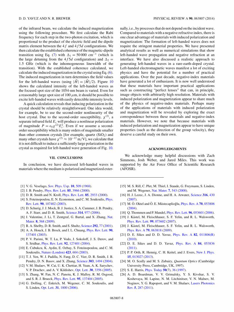
For concreteness, we next focus on a specific scheme forthe implementation of these ideas in a model atomic system.We discuss possible experimental implementation in a rare-earth-doped crystal later in the paper. As shown in Fig. 3, topolarize and magnetize the medium, we utilize second-ordernonlinearity (χ (2)) using three intense laser beams with fieldsEa , Eb (electric field), and Bc (magnetic field). The energylevel diagram of Fig. 3 can be realized experimentally using,for example, laser-cooled rare-earth atomic clouds or rare-earth-doped crystals [22]. The beams two-photon excite anelectric-dipole (|g〉 → |e〉) and a magnetic-dipole (|g〉 → |m〉)transition through an intermediate level |r〉. The states |g〉 and|m〉 have the same parity, which is opposite to the parity ofstates |r〉 and |e〉. To simplify the problem, we focus on the
g
r
m
e
Ea
Eb Bc
1
3
2
P, M at
FIG. 3. (Color online) Inducing polarization and magnetizationusing second-order atomic nonlinearity χ (2). Three intense laserbeams with fields Ea , Eb (electric), and Bc (magnetic), two-photon ex-cite an electric-dipole (|g〉 → |e〉) and a magnetic-dipole (|g〉 → |m〉)transition through an intermediate level |r〉. The nonlinear responseproduces polarization and magnetization at the sum frequency ofω = ωa + ωb = ωa + ωc.
second-order response of Fig. 3 and ignore other nonlinearprocesses. The polarization and magnetization induced in themedium are
P = Ndgeρge,(6)
M = Nμgmρgm.
Here N is the density of radiators, and we have definedP ≡ | �P | and M ≡ | �M|. The quantities dge and μgm arethe electric and magnetic dipole matrix elements betweenrespective states. ρge and ρgm are the coherences, and withinthe perturbative limit they are given by
ρgm = �a�b
4(1 + ir/2)(2 + im/2),
(7)ρge = �a�c
4(1 + ir/2)(3 + ie/2).
In Eq. (7), the quantities �a = Eadgr/�, �b = Ebdrm/�,and �c = Bcμre/� are the Rabi frequencies of the appliedfields. The detunings from respective levels are definedas 1 = (ωr − ωg) − ωa , 2 = (ωm − ωg) − (ωa + ωb), and3 = (ωe − ωg) − (ωa + ωc). r , e, and m are the decayrates of the respective levels. The microscopic coherencescalculated using Eq. (7) produce the macroscopic polarizationand magnetization at the sum frequency of ω = ωa + ωb =ωa + ωc. The induced polarization and magnetization theninteract with the electric and magnetic field components (Eand H ) of the probe wave to produce left-handed wavesunder appropriate conditions. We note, once again, the essen-tial difference of our approach compared to negative-indexmaterials. In negative-index materials, the medium wouldbe polarized and magnetized by the probe wave itself. Thisessentially means that the coherences of the magnetic-dipoleand electric-dipole transitions would be proportional to theelectric and magnetic field components of the probe wave. In
063807-3

D. D. YAVUZ AND N. R. BREWER PHYSICAL REVIEW A 90, 063807 (2014)
contrast, in our approach, the coherences of Eq. (7) are inducedexternally with additional laser beams.
IV. LEFT-HANDED WAVE INTENSITY
A key advantage of the proposal of this paper is thatthese effects can be observed at low atomic densities. Thereis not a strict density threshold as there is for constructingnegative-index materials. Rather, the density of radiators limitsthe magnitudes of the induced polarization and magnetization,which in turn limit the E and H fields (and thereforethe intensity) of the left-handed waves. Figure 4 showsthe calculated relationship between atomic density and left-handed wave generation. In these calculations, we consider amodel atomic system with electric and magnetic dipole matrixelements dge = ea0 (e is electron charge, a0 is Bohr radius) andμgm = μB (μB is Bohr magneton). We also assume the idealcase of maximum coherence for the respective transitions;i.e., ρge ≈ ρgm ≈ 1/2. Such high coherences would requireRabi frequencies for the fields of order the detunings from therespective transitions, � ∼ . Under these conditions, for agiven atomic density N , we calculate the maximum possiblepolarization and magnetization that can be achieved in thematerial [Eq. (6)], which in turn determines the field valuesfor the left-handed waves (using | �H | = | �M|/2 and | �E| =| �P |/2ε0). We find that the maximum possible magnetizationof the material places a more stringent requirement on theintensity of the waves than that of the polarization. Thisis similar to the problem of constructing negative-indexmaterials where the strength of the magnetic interaction istypically the chief difficulty. In Fig. 4, we plot the intensityof the left-handed waves that can be formed as the atomicdensity is varied. We find that even at atomic densities aslow as 1012/cm3, left-handed waves can be formed withintensities that can be measured with state-of-the-art detectiontechniques. In contrast, all negative-index proposals in atomic
FIG. 4. (Color online) The calculated intensity of the left-handedwaves that can be formed as the atomic density is varied. For atomicdensities of 1012/cm3 (which is achievable with most vapor cellsor laser-cooled ultracold clouds), left-handed waves with intensitiesof about 1 pW/cm2 can be formed. In contrast, all negative-indexproposals in atomic systems require densities exceeding 1016/cm3.
systems require densities exceeding 1016/cm3 [17–23]. As aresult, our proposal may be the only practical proposal with thepossibility to observe left-handed waves in atomic systems.
V. NUMERICAL SIMULATIONS
We proceed with a discussion of the numerical simu-lations [28]. To facilitate the simulations, we consider TEwaves in two spatial dimensions x and y with electricand magnetic field components �E = zEz(x,y,t) and �H =xHx(x,y,t) + yHy(x,y,t). The corresponding polarizationand magnetization components are �P = zPz(x,y,t) and�M = xMx(x,y,t) + yMy(x,y,t). With these components,
Maxwell’s equations written in a form most suitable for thefinite-difference technique are
∂Ez
∂t= 1
ε0
(∂Hy
∂x− ∂Hx
∂y
)− 1
ε0
∂Pz
∂t,
∂Hx
∂t= − 1
μ0
∂Ez
∂y− ∂Mx
∂t, (8)
∂Hy
∂t= 1
μ0
∂Ez
∂x− ∂My
∂t.
We take the polarization and magnetization to be knownfunctions of space and time (externally induced) and numeri-cally integrate Eqs. (8) to find the electric and magnetic fieldcomponents at all time points. We perform the numericalintegration in a three-dimensional spatiotemporal grid withgrid spacings of x, y, and t . To assure numerical stability,we choose t << x/c,y/c. We start the integration withthe specified initial conditions Ez(x,y,t = 0), Hx(x,y,t = 0),and Hy(x,y,t = 0), and use the fourth-order Runge-Kuttaalgorithm to advance the field quantities in time.
Figure 5 shows pure left-handed wave propagation througha polarized and magnetized material. Here, we assumeexternally induced polarization and magnetization wavespropagating along +x direction with the functional forms:
Pz = Pz0 cos [k(x − ct)] exp[−(x − ct)2/W 2
x
],
(9)My = My0 cos [k(x − ct)] exp
[−(x − ct)2/W 2x
],
and Mx = 0. As mentioned above, in Eq. (9), the quantitiesPz0 and My0 are related through the speed of light, My0 = cPz0.We take the wavelength to be λ = 2π/k = 1 μm. The quantityWx determines the width of the wave packet and is chosento be Wx = 7 μm. For the numerical simulation of Fig. 5,we choose the initial conditions for the field values to bethe ideal case as required for left-handed wave excitationEz(x,y,t = 0) = −Pz(x,y,t = 0)/2ε0 and Hy(x,y,t = 0) =−My(x,y,t = 0)/2. Figure 5 shows the snapshots for theelectric field Ez along the x coordinate at t = 0, t = 1, andt = 60 fs. The two plots at t = 0 and t = 1 fs clearly showthat the phase velocity and therefore the k vector is orientedalong the +x direction (for visual aid, the dashed vertical line isaligned to t = 0). This is a left-handed wave since the electricand magnetic field components are oriented along +z and +y
directions, respectively. Furthermore, the group velocity of thewave is also oriented along the +x direction. As expected fromthe analytical solution discussed above, the wave propagateswithout any absorption or gain and at the speed c.
063807-4

LEFT-HANDED ELECTROMAGNETIC WAVES IN . . . PHYSICAL REVIEW A 90, 063807 (2014)
x (micron) -20 -10 0 10 20 30
Elec
tric
field
t=0
t=1 fs
t=60 fs
FIG. 5. (Color online) Finite-difference numerical simulations ofMaxwell’s equations that demonstrate left-handed waves inside amaterial with induced polarization and magnetization. The plots showthe snapshots for the electric field of a wave packet at three differentinstants in time, t = 0, t = 1, and t = 60 fs. Both the phase andgroup velocities are oriented along the +x direction. The electric andmagnetic field components are oriented along +z and +y directions,respectively.
Figure 6 shows the results of numerical simulations wherethe initial field values are chosen to be Ez(x,y,t = 0) =Hy(x,y,t = 0) = 0. Other parameters are identical to thoseof the numerical simulation of Fig. 5. The plots in Fig. 6show the snapshots for the electric field Ez at t = 0, t = 1,t = 30, and t = 60 fs, respectively. In addition to a left-handedwave, a right-handed wave of appropriate amplitude is formed.This result can be understood as follows. From superpositionprinciple, we may add any homogeneous solution to Maxwell’sequations to the left-handed wave solutions. Homogeneoussolutions are the solutions without any driving terms, i.e.,without any externally induced polarization and magnetization(right-handed waves). If the initial conditions for the fields aredifferent from those required for pure left-handed wave exci-tation [Ez(x,y,t = 0) = −Pz(x,y,t = 0)/2ε0 andHy(x,y,t =0) = −My(x,y,t = 0)/2], then we may add an appropriateright-handed wave solution such that the initial condition issatisfied. For zero-field initial condition, as is the case in thenumerical simulation of Fig. 6, the right-handed componenthas an equal magnitude and opposite phase such that there isperfect destructive interference with the left-handed wave att = 0.
We next present a more detailed analysis of refraction atan interface. Similar to the discussion of Fig. 2, consider anelectromagnetic wave refracting from free space to a materialwith induced polarization and magnetization (medium 2)
-30 -20 -10 0 10 20 30x (micron)
Elec
tric
field
t=0
t=1 fs
t=30 fs
t=60 fs
left-handed right-handed
FIG. 6. (Color online) Wave propagation with the initial fieldvalues chosen to be Ez(x,y,t = 0) = Hy(x,y,t = 0) = 0. In additionto a left-handed wave, a right-handed wave with equal amplitude andopposite initial phase (phase at t = 0) is formed.
but now with an arbitrary angle as shown in Fig. 7(a).The boundary conditions at the interface state that (i) thetangential components of E and H must be continuous atthe boundary and (ii) the normal components of B and D mustbe continuous at the boundary. We assume that in medium 2we are able to prepare appropriately phased polarization andmagnetization with �M = −2 �H and �P = −2ε0 �E. Note thatusing the geometry of Fig. 7(a), the E field only has a tangentialcomponent whereas the H field has both a tangential anda normal component. We therefore have �E2 = �E1, and also�Ht2 = �Ht1. The requirement that �Bn2 = �Bn1 further implies
that �Hn2 + �Mn = �Hn1, which with the assumed magnetization
H1
Hn1
Ht1 H2
Hn2
Ht2
E1 E2
k1 k2 k1 k2
FIG. 7. (Color online) (a) Beam refraction from a “normal,”right-handed material into a material with induced polarizationand magnetization. The wave refracts with a negative angle ofrefraction. (b) The time-reversed case where the wave refractsfrom the material with induced polarization and magnetization intoright-handed material.
063807-5

D. D. YAVUZ AND N. R. BREWER PHYSICAL REVIEW A 90, 063807 (2014)
0,μ0
P = M = 0 P, M
0,μ0
P = M = 0 P, M0,μ0
P = M = 0 P, M
(a) t = 0 fs
0,μ0
P = M = 0 P, M
x (micron)10 20 30102030 0
M
PH
E
(b) t = 30 fs
(c) t = 60 fs (d) t = 90 fs
k k
x (micron)10 20 30102030 0
x (micron)10 20 30102030 0
x (micron)10 20 30102030 0
FIG. 8. (Color online) Wave refraction from a material with induced polarization and magnetization into free space. Here, we assumepolarization and magnetization waves in the material propagating along the k vector as shown in Fig. 4(b) and start with zero initial fieldvalues, Ez(x,y,t = 0) = Hy(x,y,t = 0) = 0. Before the polarization and magnetization exist in the region on the right, there is no generatedEM wave (a). Once the induced polarization and magnetization appear at the interface, a refracted right-handed wave appears in the region offree space (b). As the polarization and magnetization generate the left-handed wave in the region of x > 0 a refracted wave is generated alongwith it in the region of free space. The direction of the polarization, magnetization, electric field, and magnetic field are indicated (c). After thepulse of polarization and magnetization has completely entered the region of x > 0 the left-handed wave inside the material and the refractedright-handed wave outside the material become two separate pulses and propagate as expected (d).
yields �Hn2 = − �Hn1. From these considerations, we concludethat the beam will refract at the interface with a negativeangle, with the k vectors as shown in Fig. 7(a). Note thatthis analysis is very similar to Veselago’s original analysis ofwave refraction into a negative-index material [1]. Figure 7(b)shows the time-reversed case where the wave refracts from thematerial with induced polarization and magnetization into freespace.
In Fig. 8, we numerically simulate refraction of a wave fromthe material with induced polarization and magnetization intofree space [i.e., for the conditions of Fig. 7(b)]. Here, weassume polarization and magnetization waves in the materialpropagating along the k vector as shown in Fig. 7(b), awayfrom the interface. Similar to the numerical simulation ofFig. 6, we start with zero initial field values, Ez(x,y,t = 0) =Hy(x,y,t = 0) = 0. The induced polarization and magnetiza-tion generates the left-handed wave in the material, which inturn refracts into free space. The false-color plots in Fig. 8show the snapshots for the electric field Ez in the two spatialdimensions, x and y, at t = 0, t = 30, t = 60, and t = 90 fs.The boundary between the two regions is at x = 0. The regionx < 0 is free space and the region x > 0 is the material with
induced polarization and magnetization. As expected, the waverefracts into free space with a negative angle of refraction.
VI. IMPLEMENTATION USING ARARE-EARTH-DOPED CRYSTAL
Rare-earth ions in doped crystals at cryogenic temperaturesoffer a promising route for the studies of left-handed electro-magnetic waves in atomic systems. The chief difficulty forobserving these effects in the optical region of the spectrum isthe weakness of the magnetic response. Although externallypolarizing a sample is relatively straightforward, producingsubstantial magnetization requires a strong magnetic-dipoletransition with a narrow linewidth, which is challenging toachieve. This challenge can be overcome using the intra-configurational 4f → 4f transitions of rare-earth ions [29–34]. Rare earths typically form trivalent ions in crystals withonly 4f electrons remaining in the outer shell in the groundconfiguration. The 4f shell is tightly bound to the nucleusand the 4f electronic configuration interacts weakly withthe crystal environment. As a result, the intraconfigurational4f → 4f transitions are sharp, and they are very much like
063807-6

LEFT-HANDED ELECTROMAGNETIC WAVES IN . . . PHYSICAL REVIEW A 90, 063807 (2014)
free-ion transitions that are only weakly perturbed by the crys-tal field. At cryogenic temperatures, homogeneous linewidthswell below 1 MHz are routinely observed for the 4f → 4f
transitions [29,35,36]. Optically excited fluorescence levellifetimes exceeding 1 ms have also been demonstrated in thesesystems. Furthermore, due to the absence of atomic motion,there is neither Doppler broadening nor atomic diffusion.Because of these properties, rare-earth-doped crystals moreclosely resemble ultracold clouds than warm vapors.
Another attractive feature of these systems is that dopingfractions of ∼0.1% are routinely used, which corresponds torare-earth ion densities exceeding 1019/cm3. These densitiesare much higher than what can be achieved in neutral ultracoldclouds or atomic vapors. The rare-earth ion-ion interactions donot significantly effect the 4f configuration at these densities.However, because of the interaction with the crystal field, thereis an inhomogeneous broadening of the intraconfigurational4f → 4f lines [29,35]. This broadening depends on thecrystal host and the specific levels but is typically a fewGHz. This broadening is unusually small for a solid-statesystem, which is again a result of the 4f configuration beingrelatively well shielded from the cyrstalline environment.These attractive properties have been essential in recentdemonstrations of quantum interference effects such as EITand slow light in rare-earth-doped crystals [37–42].
4f6 7F0
4f6 5D1
Ea
Δ2
4f55d
Δ1
EbM at ω
FIG. 9. (Color online) Proposed scheme for exciting left-handedwaves in a Eu-doped crystal. The magnetization (M) is inducedusing the 7F 0 → 5D1 strong magnetic-dipole transition of the Eu3+
ions. Two-photon excitation with infrared light at a wavelength of1054 nm is used to generate the coherence between the two levels.The two-photon excitation is through the 4f 5d configuration as theintermediate level. The polarization can be induced using a number ofprocesses. One approach would be to use the second-order nonlinearresponse of the host crystal. The second-order susceptibility (χ (2)) ofthe crystal can produce a nonlinear polarization P = ε0χ
(2)E2c using
a separate infrared laser with field amplitude Ec.
FIG. 10. (Color online) The predicted intensity of left-handedwaves that can be excited inside a 0.1% doped Eu:YSO crystal. Herewe take the power of the infrared laser beam (λ = 1054 nm) to be 1 Wand calculate the magnetization that can be induced in the materialas we vary the focused beam size. The induced magnetization inturn determines the field values and therefore the intensity for theleft-handed waves.
We have identified europium (Eu)–doped crystals to beparticularly suitable for the studies of left-handed waves [43].One of the main reasons is that we have found a strongmagnetic-dipole transition from the ground level in Eu3+,7F 0 → 5D1 transition in the 4f shell at an experimentallyaccessible wavelength of 527 nm. Figure 9 shows a specificscheme that can be used to magnetize the crystal. To generatethe coherence between the two levels, two-photon excitationwith an intense beam of infrared light at a wavelength of 1054nm can be used. The transitions within the 4f shell in a free ionare dipole forbidden due to parity selection rules (inside thecrystal, these transitions become weakly dipole allowed due tothe mixing with the crystal field; however, this mixing is small).However, a two-photon excitation using the high-lying 4f 5d
configuration as an intermediate level can be used [44–47].The goal would be to produce a reasonably large coherenceof the magnetic dipole transition, ρgm, and therefore producea substantial magnetization at the doubled frequency. To findthe magnetic-dipole matrix element between the 7F 0 and 5D1
levels of the 4f shell, we used Cowan’s atomic structurecode [48]. Cowan’s code gives the magnetic-dipole decay rate(Einstein A coefficient) from the excited level 5D1 to 7F 0 tobe 7.1 s−1. We have found two references that have eitherexperimentally measured or numerically calculated this decayrate. They specify this decay rate to be 10.3 s−1 [49] and10.8 s−1 [50], respectively, which is in reasonable agreementwith our calculation using Cowan’s code. Based on the decayrate, we calculate the magnetic-dipole matrix element for the7F 0 → 5D1 transition to be μgm ≡ 〈J ||μ||J ′〉 ≈ 0.1μB , whichis reasonably strong.
Figure 10 shows the calculated intensity of left-handedwaves that can be excited in a Eu-doped crystal with experi-mental parameters that can be achieved relatively easily. Herewe assume a 0.1% doped crystal and take the power of the1054-nm infrared beam to be 1 W. For a given focused spot size
063807-7
D. D. YAVUZ AND N. R. BREWER PHYSICAL REVIEW A 90, 063807 (2014)
of the infrared beam, we calculate the induced magnetizationusing the following procedure. We first calculate the Rabifrequency for each step in the two-photon excitation, which isproportional to the product of the electric field and the dipolematrix element between the 4f and 4f 5d configurations. Wethen calculate the established coherence of the magnetic-dipoletransition using Eq. (7) with 1 = 50 000 cm−1 (which isthe large detuning from the 4f 5d configuration) and 2 =1.5 GHz (which is the inhomogeneous linewidth of thetransition). With the established coherence calculated, wecalculate the induced magnetization in the crystal using Eq. (6).The induced magnetization in turn determines the field valuesfor the left-handed waves (using | �H | = | �M|/2). Figure 10shows the calculated intensity of the left-handed waves asthe focused spot size of the 1054-nm beam is varied. Even fora reasonably large spot size of 100 μm, it should be possible toexcite left-handed waves with easily detectible intensity levels.
A quick calculation reveals that inducing polarization in thecrystal should be relatively straightforward. One idea would,for example, be to use the second-order nonlinearity of thehost crystal. Due to the second-order susceptibility, χ (2), aseparate infrared field Ec will produce a nonlinear polarizationof magnitude P = ε0χ
(2)E2c . Even if we assume a second-
order susceptibility which is many orders of magnitude smallerthan other common crystals [for example, quartz (SiO2) andmany other crystals have χ (2) ≈ 10−12 m/V], we calculate thatit is not difficult to induce a sufficiently large polarization in thecrystal as required for left-handed wave generation of Fig. 10.
VII. CONCLUSIONS
In conclusion, we have discussed left-handed waves inmaterials where the medium is polarized and magnetized exter-
nally, i.e., by processes that do not depend on the incident wave.Compared to materials with a negative refractive index, there isone clear advantage of materials with induced polarization andmagnetization: The formation of left-handed waves does notrequire the stringent material properties. We have presentedanalytical results as well as numerical simulations that showleft-handed wave propagation and negative refraction at aninterface. We have also discussed a realistic approach togenerating left-handed waves in a rare-earth-doped crystal.Left-handed electromagnetic waves manifest a lot of excitingphysics and have the potential for a number of practicalapplications. Over the past decade, negative-index materialshave generated a lot of enthusiasm. It is now well understoodthat these materials have important practical applicationssuch as constructing “perfect lenses” that can, in principle,image objects with arbitrarily high resolution. Materials withinduced polarization and magnetization appear to share muchof the physics of negative-index materials. Perhaps manyof the applications of materials with induced polarizationand magnetization will be revealed by exploring the exactcorrespondence between these materials and negative-indexmaterials. However, we note that because materials withinduced polarization and magnetization appear to have uniqueproperties (such as the direction of the group velocity), theydeserve a careful study on their own.
ACKNOWLEDGMENTS
We acknowledge many helpful discussions with ZachSimmons, Josh Weber, and Jared Miles. This work wassupported by the Air Force Office of Scientific Research(AFOSR).
[1] V. G. Veselago, Sov. Phys. Usp. 10, 509 (1968).[2] J. B. Pendry, Phys. Rev. Lett. 85, 3966 (2000).[3] D. R. Smith and N. Kroll, Phys. Rev. Lett. 85, 2933 (2000).[4] S. Foteinopoulou, E. N. Economou, and C. M. Soukoulis, Phys.
Rev. Lett. 90, 107402 (2003).[5] D. Schurig, J. J. Mock, B. J. Justice, S. A. Cummer, J. B. Pendry,
A. F. Starr, and D. R. Smith, Science 314, 977 (2006).[6] J. Valentine, J. Li, T. Zentgraf, G. Bartal, and X. Zhang, Nat.
Mater. 8, 568 (2009).[7] R. A. Shelby, D. R. Smith, and S. Shultz, Science 292, 77 (2001).[8] A. A. Houck, J. B. Brock, and I. L. Chuang, Phys. Rev. Lett. 90,
137401 (2003).[9] P. V. Parimi, W. T. Lu, P. Vodo, J. Sokoloff, J. S. Derov, and
S. Sridhar, Phys. Rev. Lett. 92, 127401 (2004).[10] E. Cubukcu, K. Aydin, E. Ozbay, S. Foteinopoulou, and C. M.
Soukoulis, Nature (London) 423, 604 (2003).[11] T. J. Yen, W. J. Padilla, N. Fang, D. C. Vier, D. R. Smith, J. B.
Pendry, D. N. Basov, and X. Zhang, Science 303, 1494 (2004).[12] V. M. Shalaev, W. Cai, U. K. Chettiar, H. Yuan, A. K. Sarychev,
V. P. Drachev, and A. V. Kildishev, Opt. Lett. 30, 3356 (2005).[13] S. Zhang, W. Fan, N. C. Panoiu, K. J. Malloy, R. M. Osgood,
and S. R. J. Brueck, Phys. Rev. Lett. 95, 137404 (2005).[14] G. Dolling, C. Enkrich, M. Wegener, C. M. Soukoulis, and
S. Linden, Opt. Lett. 31, 1800 (2006).
[15] M. S. Rill, C. Plet, M. Thiel, I. Staude, G. Freymann, S. Linden,and M. Wegener, Nat. Mater. 7, 543 (2008).
[16] H. J. Lezec, J. A. Dionne, and H. A. Atwater, Science 316, 430(2007).
[17] M. O. Oktel and O. E. Mustecaplioglu, Phys. Rev. A 70, 053806(2004).
[18] Q. Thommen and P. Mandel, Phys. Rev. Lett. 96, 053601 (2006).[19] J. Kastel, M. Fleischhauer, S. F. Yelin, and R. L. Walsworth,
Phys. Rev. Lett. 99, 073602 (2007).[20] J. Kastel, M. Fleischhauer, S. F. Yelin, and R. L. Walsworth,
Phys. Rev. A 79, 063818 (2009).[21] D. E. Sikes and D. D. Yavuz, Phys. Rev. A 82, 011806(R)
(2010).[22] D. E. Sikes and D. D. Yavuz, Phys. Rev. A 84, 053836
(2011).[23] P. P. Orth, R. Hennig, C. H. Keitel, and J. Evers, New J. Phys.
15, 013027 (2013).[24] M. O. Scully and M. S. Zubairy, Quantum Optics (Cambridge
University Press, Cambridge, UK, 1997).[25] S. E. Harris, Phys. Today 50(7), 36 (1997).[26] A. D. Boardman, V. V. Grimalsky, Y. S. Kivshar, S. V.
Koshevaya, M. Lapine, N. M. Litchinitser, V. N. Malnev, M.Noginov, Y. G. Rapoport, and V. M. Shalaev, Lasers PhotonicsRev. 5, 287 (2011).
063807-8

LEFT-HANDED ELECTROMAGNETIC WAVES IN . . . PHYSICAL REVIEW A 90, 063807 (2014)
[27] S. Xiao, V. P. Drachev, A. V. Kildishev, N. Xingjie, U. K.Chettiar, Y. Hsiao-Kuan, and V. M. Shalaev, Nature (London)466, 735 (2010).
[28] K. S. Yee, IEEE Trans. Antennas Propagat. AP-14, 302 (1966).[29] R. M. Macfarlane, J. Lumin. 100, 1 (2002).[30] B. G. Wybourne, Spectroscopic Properties of Rare-Earths (John
Wiley & Sons, New York, 1965).[31] K. N. R. Taylor and M. I. Darby, Physics of Rare Earth Solids
(Chapman and Hall, London, 1972).[32] G. S. Ofelt, J. Chem. Phys. 38, 2171 (1963).[33] G. S. Ofelt, J. Chem. Phys. 37, 511 (1962).[34] G. H. Dieke and H. M. Crosswhite, Appl. Optics 2, 675 (1963).[35] R. M. Macfarlane and R. M. Shelby, J. Lumin. 36, 179
(1987).[36] R. W. Equall, Y. Sun, R. L. Cone, and R. M. Macfarlane, Phys.
Rev. Lett. 72, 2179 (1994).[37] B. S. Ham, P. R. Hemmer, and M. S. Shahriar, Opt. Commun.
144, 227 (1997).[38] B. S. Ham, P. R. Hemmer, and M. S. Shahriar, Phys. Rev. A 59,
R2583(R) (1999).[39] A. V. Turukhin, V. S. Sudarshanam, M. S. Shahriar, J. A. Musser,
B. S. Ham, and P. R. Hemmer, Phys. Rev. Lett. 88, 023602(2001).
[40] J. Klein, F. Beil, and T. Halfmann, J. Phys. B: At. Mol. Opt.Phys. 40, S345 (2007).
[41] J. Klein, F. Beil, and T. Halfmann, Phys. Rev. Lett. 99, 113003(2007).
[42] J. Klein, F. Beil, and T. Halfmann, Phys. Rev. A 78, 033416(2008).
[43] B. Lauritzen, N. Timoney, N. Gisin, M. Afzelius, H. deRiedmatten, Y. Sun, R. M. Macfarlane, and R. L. Cone, Phys.Rev. B 85, 115111 (2012).
[44] R. T. Wegh and A. Meijerink, Phys. Rev. B 60, 10820(1999).
[45] L. van Pieterson, M. F. Reid, G. W. Burdick, and A. Meijerink,Phys. Rev. B 65, 045114 (2002).
[46] L. van Pieterson, M. F. Reid, R. T. Wegh, S. Soverna, andA. Meijerink, Phys. Rev. B 65, 045113 (2002).
[47] L. van Pieterson, M. F. Reid, and A. Meijerink, Phys. Rev. Lett.88, 067405 (2002).
[48] R. D. Cowan, The Theory of Atomic Structure andSpectra (University of California Press, Oakland,1981).
[49] M. J. Weber and R. F. Schaufele, J. Chem. Phys. 43, 1702(1965).
[50] W. F. Krupke, Phys. Rev. 145, 325 (1966).
063807-9