Embed Size (px)
Citation preview
Thank you very much for purchasing Panasinic products. Read this Instruction Manual carefully and thoroughly for the correct and optimum use of this product. Kindly keep this manual in a convenient place for quick reference.
MJE-DP2 No.0048-50V
SPECIFICATIONS1
Note: Model Nos. of North American standard type having the suffix '-P' are PNP output type.
0.15mm2 5-core oil resistant cabtyre cable, 2m long (IP67 type: 5m long)CableStandard type: 95g approx., Flat type: 120g approx., IP67 type: 370g approx., Light weight type: 70g approx.Weight
Hexagon-socket-head plug for pressure port: 1 No. (Standard type only), Pressure unit label: 1 No.Accessories
European Flat ・ IP67 types: G (PF) 1/8 female threadNorth American Standard type: NPTF 1/8female thread, Flat ・ IP67 types: NPT 1/8 female threadAsian Standard ・ Flat ・ IP67 types: Rc (PT) 1/8 female thread, Light weight type: M5 female thread
Pressureport
Over ambient temperature range -10 to +50℃: within ±1% F.S. of detected pressure at 20℃Temperature characteristics
Comparative Output 2 Green LED (lights up when Comparative Output 2 is ON)Comparative Output 1 Orange LED (lights up when Comparative Output 1 is ON)Operation
indicators
LED bar display in steps of 10% F.S. approx.Analog bar displayDisplayable pressure range -0.050 to 1.000MPa-5.0 to 100.0kPa5.1 to -101.3kPa
1 digit (However, variable in hysteresis mode and 2 digits when using psi unit)HysteresisWithin ±0.2% F.S. ±1 digitRepeatability
2.5ms or lessResponse timeIncorporatedShort-circuit protection
12 to 24V DC % Ripple P-P 10% or less+10-15
Selectable units kgf/cm2, bar, psikgf/cm2, bar, psi, mmHg, inHgApplicable fluid Non-corrosive gasPressure withstandability 1.47MPa490kPa
Rated pressure range 0 to 1.000MPa0 to 100.0kPa0 to -101.3kPaSet pressure range -0.050 to 1.000MPa-5.0 to 100.0kPa5.1 to -101.3kPa
North American (Note)European
AsianDP2-20F(-P) DP2-40N DP2-60N - DP2-21F(-P) DP2-41N DP2-61N DP2-22F(-P) DP2-42N DP2-62N- DP2-40E DP2-60E - - DP2-41E DP2-61E - DP2-42E DP2-62E
DP2-20 - DP2-60 DP2-80 DP2-21 DP2-41 DP2-61 DP2-22 DP2-42 DP2-62Standard Flat Light weightIP67 Standard StandardFlat IP67 Flat IP67
Front case: ABS, Rear case: PPS (glass fiber reinforced), Display surface: AcrylicPressure port attachment: Die-cast zinc alloy [Light weight type: POM (glass fiber reinforced), pressure port is brass (nickel plated)]Front cover (IP67 type only): Polycarbonate
Material
31/2 digit red LED display (Sampling rate: 4 times/sec. approx.)Display
Standard ・ Flat ・ Light weight types: IP40 (IEC), IP67 type: IP67 (IEC)Protection-10 to +50℃ (No dew condensation or icing allowed), Storage: -10 to +60℃Ambient temperature
35 to 85% RH, Storage: 35 to 85% RHAmbient humidity2Pollution degreeIIOvervoltage category
2,000m or lessUsable altitude
Analog voltage output
Equipped with 4 types of modes: hysteresis mode, window comparator mode, dual output mode, automatic sensitivitysetting mode (selectable by key operation)
Output modes
AsianNorth American (Standard NPN output, Flat, IP67 types)
NPN open-collector transistor・Maximum sink current: 100mA・Applied voltage: 30V DC or less (between comparative output and 0V)・Residual voltage: 1V or less (at 100mA sink current)
0.4V or less (at 16mA sink current)
<North American (Standard PNP output type), European>PNP open-collector transistor・Maximum source current: 100mA・Applied voltage: 30V DC or less
(between comparative output and +V)・Residual voltage: 2V or less (at 100mA source current)
Current consumption 50mA or lessSupply voltage
Type of pressure
1MPa type100kPa typeVacuum pressure
-101kPa typePositive pressure
Gauge pressure
Type
Mode
l No.
Item
Comparative outputsComparative Output 1Comparative Output 2
Output voltage: 1 to 5V (over rated pressure range)Zero-point: within 1V ±5% F.S.Span: within 4V ±5% F.S.Linearity: within ±1% F.S.Output impedance: 1kΩ approx.
5
1
PressureOut
put v
olta
ge (V
)
High pressure (Positive pressure type)High vacuum (Vacuum pressure type)
WARNING●
●
●
Never use this product as a sensing device for personnel protection.In case of using sensing devices for personnel protection, use products which meet laws and standards, such as OSHA, ANSI or IEC etc., for personnel protection applicable in each region or country.In case this sensor is used within Japan, SI unit must be used since use of pressure units in Japan is restricted to SI units.
DP2 Series For use outside Japan
LED Display・Digital Pressure Sensor
INSTRUCTIONMANUAL
●
●
●
●
●
●
●
●
This product has been developed / produced for industrial use only.Use within the rated pressure range.Do not apply pressure exceeding the pressure withstandability value. The diaphragm will get damaged and correct operation shall not be maintained.Make sure to carry out the wiring in the power supply off condition.Take care that wrong wiring will damage the sensor.Verify that the supply voltage variation is within the rating.If power is supplied from a commercial switching regulator, ensure that the frame ground (F.G.) terminal of the power supply is connected to an actual ground.In case noise generating equipment (switching regulator, inverter motor, etc.) is used in the vicinity of this sensor, connect the frame ground (F.G.) terminal of the equipment to an actual ground
●
●
●
●
●
●
●
●
●
Do not use during the initial transient time (0.5 sec.) after the power supply is switched on.Do not run the wires together with high-voltage lines or power lines or put them in the same raceway. This can cause malfunction due to induction.This product is suitable for indoor use only.Avoid use of standard type, flat type and light weight type of sensor in places where steam and dust is excessive.Take care that the sensor does not come in contact with water, oil, grease, or organic solvents, such as, thinner, etc.Do not insert wires, etc, into the pressure port. The diaphragm will get damaged and correct operation shall not be maintained.Do not operate the keys with pointed or sharp objects.Make sure that stress by forcible bend or pulling is not applied directly to the sensor cable joint.Extension up to total 100m is possible with 0.3mm2, or more, cable. However, in case of using this product as a CE Marking conformity product, the power wire connected to this product must be within 10m.
DP2 series is designed for use with non-corrosive gas.It cannot be used for liquid or corrosive gas.
CAUTIONS2
Standard type
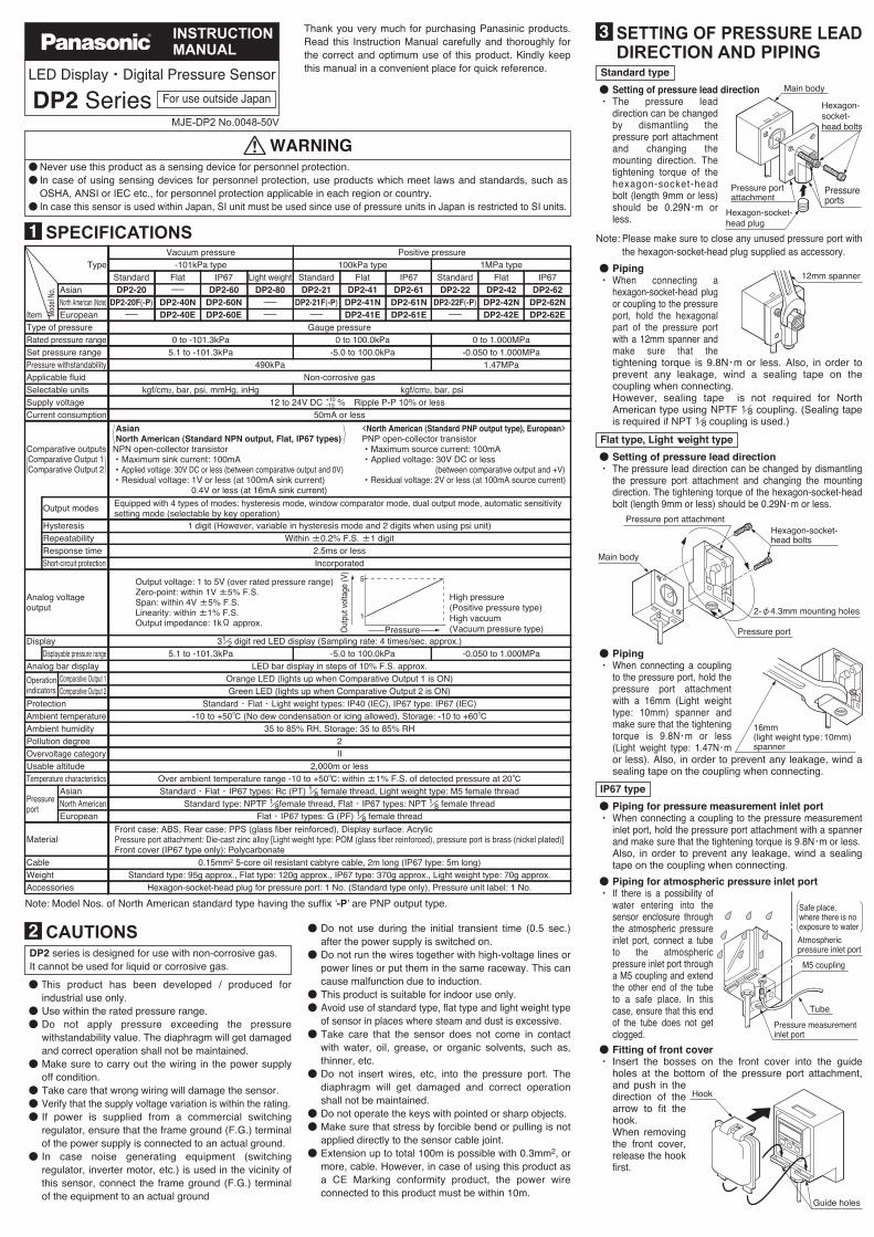
Note: Please make sure to close any unused pressure port with the hexagon-socket-head plug supplied as accessory.
●・
Setting of pressure lead directionThe pressure lead direction can be changed by dismantling the pressure port attachment and changing the mounting direction. The tightening torque of the hexagon-socket-head bolt (length 9mm or less) should be 0.29N・m or less.
Hexagon-socket-head bolts
Main body
Pressure port attachment
Hexagon-socket-head plug
Pressure ports
●・
PipingWhen connecting a hexagon-socket-head plug or coupling to the pressure port, hold the hexagonal part of the pressure port with a 12mm spanner and make sure that thetightening torque is 9.8N・m or less. Also, in order to prevent any leakage, wind a sealing tape on the coupling when connecting.However, sealing tape is not required for North American type using NPTF 1/8 coupling. (Sealing tape is required if NPT 1/8 coupling is used.)
12mm spanner
Flat type, Light weight type
●・
Setting of pressure lead directionThe pressure lead direction can be changed by dismantling the pressure port attachment and changing the mounting direction. The tightening torque of the hexagon-socket-head bolt (length 9mm or less) should be 0.29N・m or less.
Hexagon-socket-head bolts
2-φ4.3mm mounting holes
Pressure port
Pressure port attachment
Main body
●・
PipingWhen connecting a coupling to the pressure port, hold the pressure port attachment with a 16mm (Light weight type: 10mm) spanner and make sure that the tightening torque is 9.8N・m or less (Light weight type: 1.47N・mor less). Also, in order to prevent any leakage, wind a sealing tape on the coupling when connecting.
16mm (light weight type: 10mm)spanner
●・
Piping for pressure measurement inlet portWhen connecting a coupling to the pressure measurement inlet port, hold the pressure port attachment with a spanner and make sure that the tightening torque is 9.8N・m or less.Also, in order to prevent any leakage, wind a sealing tape on the coupling when connecting.
IP67 type
●・
Piping for atmospheric pressure inlet portIf there is a possibility of water entering into the sensor enclosure through the atmospheric pressure inlet port, connect a tube to the atmospheric pressure inlet port through a M5 coupling and extend the other end of the tube to a safe place. In this case, ensure that this end of the tube does not get clogged.
Atmospheric pressure inlet port
Pressure measurement inlet port
Tube
M5 coupling
Safe place, where there is no exposure to water
●・
Fitting of front coverInsert the bosses on the front cover into the guide holes at the bottom of the pressure port attachment,and push in the direction of the arrow to fit the hook.When removing the front cover, release the hook first.
Guide holes
Hook
SETTING OF PRESSURE LEAD DIRECTION AND PIPING
3

Fitting of front coverInsert the bosses on the front cover into the guide holes at the bottom of the pressure port attachment,and push in the direction of the arrow to fit the hook.When removing the front cover, release the hook first.
SETTING OF PRESSURE LEAD DIRECTION AND PIPING
● NPN output type
Note: The analog voltage output is not incorporated with a short-circuit protection circuit. Do not directly connect a power supply or a capacitive load. When using the analog voltage output, take care to connect external equipment of proper input impedance.Also, when a cable extension is used, voltage drop due to cable resistance should be taken into account.
Tr2
Tr1
1kΩ
100mA max.
100mA max.
Users’ circuitInternal circuit
(Blue) 0V
(White) Comparative Output 2
(Black) Comparative Output 1
(Gray) Analog voltage output
(Brown) +V
Color code
LoadLoad
ZD2
ZD3
ZD1
D
Sen
sor
circ
uit
(Note)12 to 24V DC+10-15 %
+
-
Symbols...D: Reverse supply polarity protection diodeZD1, ZD2, ZD3: Surge absorption zener diodeTr1, Tr2: NPN output transistor
Symbols...D: Reverse supply polarity protection diodeZD1, ZD2, ZD3: Surge absorption zener diodeTr1, Tr2: PNP output transistor
● PNP output type
Note: The analog voltage output is not incorporated with a short-circuit protection circuit. Do not directly connect a power supply or a capacitive load. When using the analog voltage output, take care to connect external equipment of proper input impedance.Also, when a cable extension is used, voltage drop due to cable resistance should be taken into account.
Users’ circuitInternal circuit
Color code
100mA max.
100mA max.
ZD1
ZD2
ZD3
Tr1
LoadLoad
(Brown) +V
(White) Comparative Output 2
(Black) Comparative Output 1
(Gray) Analog voltage output (Note)(Blue) 0V
Tr2
D
Sen
sor
circ
uit
1kΩ
12 to 24V DC+10-15 %
+
-
I/O CIRCUIT DIAGRAM5
● A sensor mounting bracket MS-DPX and MS-DPX-4 (optional) may be used.When mounting the sensor with the sensor mounting bracket, etc., the tightening torque should be 1.2N・m or less.
Note: In case mounting brackets or screws other than the sensor mounting bracket shown in the figure above are used, the length of the screws inserted into the pressure port attachment should be 5mm or less. If the length of the screws is longer than 5mm, the sensor may be damaged.
<MS-DPX>
Sensor mounting bracket MS-DPX (optional)
M4 (length 6mm) pan head screw (attached with MS-DPX)
Spring washer (attached with MS-DPX)
<MS-DPX-4>
Sensor mounting bracket MS-DPX-4 (optional)
M4 (length 6mm) pan head screw (attached with MS-DPX-4)
Spring washer (attached with MS-DPX-4)
● Panel mounting bracket MS-DPX-2 (optional) and a front protection cover DPX-04 (optional) are also available.
DP2-20
–101.3kPa
OUT2
OUT1
MODE
0-ADJ
Panel mounting bracketMS-DPX-2 (optional)(Suitable for 1 to 3.2mm thick panel)
DP2-20
-101.3kPa
OUT2
OUT1
MODE
0-ADJ
Front protection cover DPX-04 (optional)
MOUNTING OF STANDARD TYPE SENSOR
4
● When an error occurs, take the following corrective action.
Positive
pressure
type
Positive
pressure
type
Vacuum
pressure
type
Vacuum
pres
sure
type
Applied pressure exceeds the upper limit of displayable pressure range.
Applied pressure exceeds the lower limit of displayable pressure range.
Applied pressure exceeds the lower limit of displayable pressure range.
Applied pressure exceeds the upper limit of displayable pressure range.
Applied pressure at the pressure port should be brought to atmospheric pressure and zero-point adjustment should be done again.
Pressure is being applied during zero-point adjustment.
Switch off the power supply and check the load.
Corrective action
Overcurrent due to short-circuit.
Error message Cause
Applied pressure should be brought within the rated pressure range.
ERROR MESSAGES7
DP2-20 -101.3kPa
OUT2OUT1
MODE
0-ADJ
①
②③
⑥④
⑤
・
・
・
Pressing the key changes the selected mode to sensing mode, Set Value 1 (P1) set mode and Set Value 2 (P2) set mode.In the sensing mode, if the key is pressed continuously for about 3 sec., key-protect can be set/released.In the sensing mode, if the mode selection key is pressed while pressing the increment key ( ), the initial setting mode is obtained.
Lights up when Comparative Output 1 is ON.②Comparative Output 1operation indicator(Orange)Comparative Output 2operation indicator(Green)
Displays measured pressure, settings, error messages and key-protect status.
Description Function
①31/2 digit LEDdisplay (Red)
Lights up when Comparative Output 2 is ON.③
⑥
In t
he s
ensi
ng m
ode,
if
both
the
key
s ar
e pr
esse
d si
mul
tane
ousl
y, z
ero-
poin
t adj
ustm
ent i
s do
ne.
・
・
・
In the initial setting mode, pressing the key changes the settable digit.In the Set Value 1, 2 modes, pressing the key changes the set value to the high pressure side in case of positive pressure type sensor and to the high vacuum side in case of vacuum pressure type sensor.In the sensing mode, if the key is pressed continuously for 4 sec. or more, the display shows peak hold value.
④Increment key( )
・
・
・
In the initial setting mode, pressing the key changes the set conditions.In the Set Value 1, 2 modes, pressing the key changes the set value to the low pressure side in case of positive pressure type sensor and to the low vacuum side in case of vacuum pressure type sensor.In the sensing mode, if the key is pressed continuously for 4 sec. or more, the display shows bottom hold value.
⑤Decrement key( )
Mode selection key( )MODE
FUNCTIONAL DESCRIPTION6
● The common hysteresis of the comparative outputs can be set, as desired, with the set values.
Hysteresis mode ( )
Comparative Output 1
Comparative Output 2
Hysteresis:1 digit or more
2 digits or more when using psi unit
ON
OFFON
OFF
0 Set Value 1 (P1) Set Value 2 (P2)High pressure (Positive pressure type)High vacuum (Vacuum pressure type)
Hysteresis
● The comparative outputs can be turned ON or OFF by a pressure which is within the pressure range set by Set Value 1 and Set Value 2.
Window comparator mode ( )
When operating in window comparator mode ( ) Set Value 1 (P1) and Set Value 2 (P2) should be set with a difference of 3 digits or more. However, when the pressure unit is set to 'psi' ( ), the difference should be 6 digits or more.
Hysteresis: 1 digit2 digits when using psi unit
High pressure (Positive pressure type)High vacuum (Vacuum pressure type)
Comparative Output 1
Comparative Output 2
ON
OFFON
OFF
0 Set Value 1 (P1) Set Value 2 (P2)
Hysteresis Hysteresis
● Using actual objects, if the pressure values for OK objects and NG objects are input, then the sensor is automatically set to the optimum pressure value (mid-value).
Automatic sensitivity setting mode ( )
Comparative Output 1
Comparative Output 2
ON
OFFON
OFF
0 Set Value 1 (P1) Set Value 2 (P2)High pressure (Positive pressure type)High vacuum (Vacuum pressure type)
Set Value 3 (P3)
Hysteresis
Hysteresis: 1 digit2 digits when using psi unit
● The outputs can be put to different use such as detection of different kinds of objects, control function, alarm function etc.
Dual output mode ( )
High pressure (Positive pressure type)High vacuum (Vacuum pressure type)
Comparative Output 1
Comparative Output 2
ON
OFFON
OFF
0 Set Value 1 (P1) Set Value 2 (P2)
Hysteresis
Hysteresis: 1 digit2 digits when using psi unit
OUTPUT MODES & THEIR CHARACTERISTICS
9
Analog bar display for positive pressure type sensor
Atm. pressure condition High pressure condition
Atm. pressure condition High vacuum condition
Analog bar display for vacuum pressure type sensor
●
●
Pressure changes are displayed in an analog fashion by using LED bars.Hence, any sudden changes in pressure can be detected at a glance.The analog bar display shows the measured pressure, irrespective of the pressure unit, in steps of 10% F.S. approx.Please refer to ' SETTING ② Initial setting' for the procedure to change to analog bar display.
11
DP2-21 100kPa
OUT2OUT1
MODE
0-ADJ
DP2-21 100kPa
OUT2OUT1
MODE
0-ADJ
DP2-21 100kPa
OUT2OUT1
MODE
0-ADJ
DP2-20 -101.3kPa
OUT2OUT1
MODE
0-ADJ
DP2-20 -101.3kPa
OUT2OUT1
MODE
0-ADJ
DP2-20 -101.3kPa
OUT2OUT1
MODE
0-ADJ
ANALOG BAR DISPLAY8●●
The pressure unit can be selected as per customer's requirement.In case of positive pressure type, the pressure unit can be changed from International System of Units (SI) 'kPa' or 'MPa' to 'kgf/cm2', 'bar' or 'psi'. In case of vacuum pressure type, the pressure unit can be changed from International System of Units (SI) 'kPa' to 'kgf/cm2', 'bar', 'psi', 'mmHg' or 'inHg'.
・
・
When the pressure unit is changed, the set values and the measured value are automatically converted.Please refer to ' SETTING ② Initial setting' for the procedure to change the pressure unit.
11
Note: 'MPa' in case of DP2-22□, DP2-42□ and DP2-62□.
inHg kPa (Note) kgf/cm2
mmHg psi bar
: Positive pressure type: Vacuum pressure type
International System of Units (SI)
PRESSURE UNITS10

③ Setting of pressure values
● Comparative outputs' [Set Value 1 (P1)], [Set Value 2 (P2)] and [Set Value 3 (P3)] are set.
・
・
・・
The setting of Set Value 2 (P2) with respect to Set Value 1 (P1) can only be towards the high pressure side in case of the positive pressure type sensor and only towards the high vacuum side in case of the vacuum pressure type sensor.Set Value 3 (P3) is automatically set to the mid-value of Set Value 1 (P1) and Set Value 2 (P2). However, if Set Value 1 (P1) is set to a value on the vacuum pressure side for a positive pressure type sensor or to the positive pressure side for a vacuum pressure type sensor, Set Value 3 (P3) is automatically set to the mid-value of 'zero' (atmospheric pressure) and Set Value 2 (P2). Further, if both, Set Value 1 (P1) and Set Value 2 (P2) are set to a value on the vacuum pressure side for a positive pressure type sensor or to the positive pressure side for a vacuum pressure type sensor, Set Value 3 (P3) is automatically set to 'zero' (atmospheric pressure).The automatically set Set Value 3 (P3) can be changed manually.Since display of error messages is not possible during pressure value setting in the automatic sensitivity setting mode, make sure that the sensor is used within the rated pressure range.
For the case when the output mode is set to automatic sensitivity setting mode ( )
Set to Set Value 1 (P1) set mode
・
・
and Set Value 1 (P1) which is being set are displayed alternately.The figure on the left shows the display of a vacuum pressure type sensor when the pressure unit has been set to 'kPa'.
・In the sensing mode, press key.MODEDP2-20 -101.3kPa
OUT2OUT1
MODE
0-ADJ
DP2-20 -101.3kPa
OUT2OUT1
MODE
0-ADJ
Displayed alternately
Enter Set Value 1 (P1)
・Within the required permissible pressure range, having created a pressure state which is nearest to the atmospheric pressure, press key.
・
・
・
The pressure value at the time of pressing key is entered as Set Value 1 (P1). Set Value 1 (P1) and
are displayed alternately.If the set pressure range is exceeded, either (upper limit exceeded) or (lower limit exceeded) are displayed and Set Value 1 (P1) is set automatically to the upper or lower limit of the set pressure range.The setting of Set Value 1 (P1) can be repeated several times in the Set Value 1 (P1) set mode.
DP2-20 -101.3kPa
OUT2OUT1
MODE
0-ADJ
DP2-20 -101.3kPa
OUT2OUT1
MODE
0-ADJ
Displayed alternately
Set to Set Value 2 (P2) set mode
・In the Set Value 1 (P1) set mode, presskey.
and Set Value 2 (P2) which isbeing set are displayed alternately.
MODE
DP2-20 -101.3kPa
OUT2OUT1
MODE
0-ADJ
DP2-20 -101.3kPa
OUT2OUT1
MODE
0-ADJ
Displayed alternately
Enter Set Value 2 (P2)
・Within the required permissible pressure range, having created a pressure state which is nearest to the high pressure end (for a positive pressure type sensor) or the high vacuum end (for a vacuum pressure type sensor), press key.
・
・
・
The pressure value at the time of pressing key is entered as Set Value 2 (P2). Set Value 2 (P2) and
are displayed alternately.If the set pressure range is exceeded, either (upper limit exceeded) or (lower limit exceeded) are displayed and Set Value 2 (P2) is set automatically to the upper or lower limit of the set pressure range.The setting of Set Value 2 (P2) can be repeated several times in the Set Value 2 (P2) set mode.
DP2-20 -101.3kPa
OUT2OUT1
MODE
0-ADJ
DP2-20 -101.3kPa
OUT2OUT1
MODE
0-ADJ
Displayed alternately
Set to sensing mode
・Press key.・
・
The sensor returns to sensing mode after Set Value 1 (P1) and Set Value 2 (P2) have been set.Since the values which have been set are stored in an EEPROM, they are not erased even if the power supply is switched off.
MODEDP2-20 -101.3kPa
OUT2OUT1
MODE
0-ADJ
● [Set Value 1 (P1)] and [Set Value 2 (P2)] of the comparative outputs are set.
・
・
The setting of Set Value 2 (P2) with respect to Set Value 1 (P1) can only be towards the high pressure side in case of the positive pressure type sensor and only towards the high vacuum side in case of the vacuum pressure type sensor.Set Value 1 (P1) and Set Value 2 (P2) can be made common for all the output modes. However, when a changeover is made to the automatic sensitivity setting mode, since Set Value 3 (P3) has not been set, make sure to carry out the pressure value settings for the automatic sensitivity mode.
For the case when output mode is set to either the hysteresis mode ( ), window comparator mode ( ) or dual output mode ( ).
Set to Set Value 1 (P1) set mode
・
・
and Set Value 1 (P1) which is being set are displayed alternately.The figure on the left shows the display of a vacuum pressure type sensor when the pressure unit has been set to 'kPa'.
・In the sensing mode, press key.MODEDP2-20 -101.3kPa
OUT2OUT1
MODE
0-ADJ
DP2-20 -101.3kPa
OUT2OUT1
MODE
0-ADJ
Displayed alternately
Set to Set Value 2 (P2) set mode
・In the Set Value 1 (P1) set mode, presskey.
and Set Value 2 (P2) which isbeing set are displayed alternately.
MODE
DP2-20 -101.3kPa
OUT2OUT1
MODE
0-ADJ
DP2-20 -101.3kPa
OUT2OUT1
MODE
0-ADJ
Displayed alternately
If the output mode has been set to the window comparator mode ( ) in the initial setting mode, Set Value 1 (P1) and Set Value 2 (P2) should be set with a difference of 3 digits or more. However, when unit is set to 'psi', the difference should be 6 digits or more.
Enter Set Value 2 (P2)
・Using key and key, enter in a manner similar to that for entering Set Value 1 (P1).If the set pressure range is exceeded, either (upper limit exceeded) or
(lower limit exceeded) is displayed.
DP2-20 -101.3kPa
OUT2OUT1
MODE
0-ADJ
DP2-20 -101.3kPa
OUT2OUT1
MODE
0-ADJ
Displayed alternately
Enter Set Value 1 (P1)DP2-20 -101.3kPa
OUT2OUT1
MODE
0-ADJ
DP2-20 -101.3kPa
OUT2OUT1
MODE
0-ADJ
Displayed alternately
・・
・
Enter using key and key.In case of the positive pressure type sensor, if key is pressed once the set value changes towards the high pressure side by 1 digit and if key is pressed once the set value changes towards the low pressure side by 1 digit.In case of the vacuum pressure type sensor, if key is pressed once the set value changes towards the high vacuum side by 1 digit and if key is pressed once the set value changes towards the low vacuum side by 1 digit.If key or key is pressed continu-ously, the set value changes quickly.If the set pressure range is exceeded, either (upper limit exceeded) or
(lower limit exceeded) is displayed.
OUTPUT MODES & THEIR CHARACTERISTICS
'MPa' in case of DP2-22□, DP2-42□ and DP2-62□.
● The displayed pressure when the pressure port is left open is adjusted to zero.
●
●
If key-protect has been set, make sure to release key-protect before operating the keys. (Please refer to' KEY-PROTECT FUNCTION' for the procedure.)The conditions which are set are stored in an EEPROM.Please note that the EEPROM has a life span and its guaranteed life is 100,000 write operation cycles.
15
Setting procedure
①Zero-point adjustmentAdjustzero-point
②Initialsetting
Set [Display],[Output mode],and [Unit]
③Pressurevalue settingEnterSet Value 1 (P1)Set Value 2 (P2)Set Value 3 (P3)
Measurement
Commencemeasurementon completionof setting
① Zero-point adjustment
Set to sensing modeDP2-20 -101.3kPa
OUT2OUT1
MODE
0-ADJ
・The sensor will automatically enter the sensing mode when power is supplied.The figure on the left shows the display when the pressure unit and display are set to 'kPa' and 'digital display', respectively.
● Pressure [Unit], [Display] and [Output mode] of the comparative outputs are set.
② Initial setting
Perform zero-point adjustmentDP2-20 -101.3kPa
OUT2OUT1
MODE
0-ADJ
・
・
Let the pressure port be at atmospheric pressure (i.e., no applied pressure condition), and press, simultane-ously, the increment and decrement keys continuously.
is displayed and, when the fingers arereleased, zero-point adjustment is completed and the sensor returns to the sensing mode.
・ If pressure has been applied during zero-point adjustment, is displayed whenthe keys are pressed. Bring the applied pressure to atmospheric pressure (i.e., no applied pressure condition) and carry out the zero-point adjustment once again.
DP2-20 -101.3kPa
OUT2OUT1
MODE
0-ADJ
Set to initial setting modeDP2-20 -101.3kPa
OUT2OUT1
MODE
0-ADJ
・・
Initial setting is displayed.If sensor is being used for the first time, is displayed.
・In the sensing mode, press key while pressing key.
MODE
Set to sensing mode
・
・
・
The sensor returns to sensing mode after the initial conditions have been set.Since the initial conditions which have been set are stored in an EEPROM, they are not erased even if the power supply is switched off.The figure on the left shows the display when the unit and display are set to 'kPa' and 'digital display', respectively.
・ Press key.MODEDP2-20 -101.3kPa
OUT2OUT1
MODE
0-ADJ
Set initial conditions
・・
The settable digit blinks.The settable digit changes when key is pressed.
・
・
Change the setting of each digit as desired.The setting is changed when key is pressed.
DP2-20 -101.3kPa
OUT2OUT1
MODE
0-ADJ
DP2-20 -101.3kPa
OUT2OUT1
MODE
0-ADJ
3rd digit 2nd digit
Change with key.
1st digit
Unit Output mode Display
: kPa or MPa
: kgf/cm2
: bar
: psi
: Hysteresis mode
: Window comparator mode
: Digital display
: Analog bar display
: Dual output mode
: Automatic sensitivity setting mode
: mmHg
: inHg
Po
sitiv
e
pre
ssu
re t
ype
Va
cuu
m
pres
sure
type
SETTING11
・
・
Please note that the peak value and the bottom value data is erased when it is no longer displayed.The response time of the comparative outputs becomes slower during the peak hold and bottom hold display.
http://panasonic.net/id/pidsx/global
© Panasonic Industrial Devices SUNX Co., Ltd. 2015PRINTED IN JAPAN
Overseas Sales Division (Head Office) 2431-1 Ushiyama-cho, Kasugai-shi, Aichi, 486-0901, Japan Phone: +81-568-33-7861 FAX: +81-568-33-8591For sales network, please visit our website.
③ Setting of pressure values
and Set Value 1 (P1) which is being set are displayed alternately.The figure on the left shows the display of a vacuum pressure type sensor when the pressure unit has been set to 'kPa'.
In the sensing mode, press key.
In the Set Value 1 (P1) set mode, presskey.
and Set Value 2 (P2) which isbeing set are displayed alternately.
Set to Set Value 3 (P3) set mode
・
・
and the automatically set Set Value3 (P3) are displayed alternately.In caseSet Value 1 (P1) = -50.0kPaSet Value 2 (P2) = -100.0kPathenSet Value 3 (P3) = =-75.0kPa-50.0+(-100.0)
2Digits smaller than the displayed digits are discarded.
・In the Set Value 2 (P2) set mode, presskey.MODE
DP2-20 -101.3kPa
OUT2OUT1
MODE
0-ADJ
DP2-20 -101.3kPa
OUT2OUT1
MODE
0-ADJ
Displayed alternately
In case Set Value 3 (P3) is to be changed
The automatically set Set Value 3 (P3) can be manually changed to a value between Set Value 1 (P1) and Set Value 2 (P2). However Set Value 3 (P3) cannot be set to a value on the vacuum pressure side for a positive pressure type sensor or to the positive pressure side for a vacuum pressure type sensor.
Comparative Output 1
Comparative Output 2
ON
OFFON
OFF
0 Set Value 1 (P1) Set Value 2 (P2)
Hysteresis
Changeable range
High pressure (Positive pressure type)High vacuum (Vacuum pressure type)
Set Value 3 (P3)
Hysteresis: 1 digit2 digits when psi unit is used
・・
・
Enter using key and key.In case of a positive pressure type sensor, if key is pressed once, the set value changes towards the high pressure side by 1 digit and if key is pressed once, the set value changes towards the low pressure side by 1 digit.In case of a vacuum pressure type sensor, if key is pressed once the set value changes towards the high vacuum side by 1 digit and if key is pressed once the set value changes towards the low vacuum side by 1 digit.If key or key is pressed continu-ously, the set value changes quickly.If the set pressure range is exceeded, either (upper limit exceeded) or
(lower limit exceeded) is displayed.
DP2-20 -101.3kPa
OUT2OUT1
MODE
0-ADJ
DP2-20 -101.3kPa
OUT2OUT1
MODE
0-ADJ
Displayed alternately
Set to sensing mode
・Press key.・
・
The sensor returns to the sensing mode after Set Value 1 (P1), Set Value 2 (P2) and Set Value 3 (P3) have been set.Since the values which have been set are stored in an EEPROM, they are not erased even if the power supply is switched off.
MODEDP2-20 -101.3kPa
OUT2OUT1
MODE
0-ADJ
● The conditions which have been set in the initial setting and the pressure settings can be checked by the following procedure.
Please note that if any key, except key, is pressed in any setting mode, the set conditions shall get changed.
MODE
Procedure to check initial conditions
Set to sensing mode
Sensor returns to sensing mode
Sensor enters initial setting mode
Press keywhile pressing
key.
MODE
Initial conditions which have been set are displayed and can be checked.
Press key.MODE
Sensor returns to sensing mode
Procedure to check set values
Set to sensing mode
Sensor enters Set Value 2 (P2) set mode
Sensor enters Set Value 1 (P1) set mode
Press key.MODE
Set Value 1 (P1) which has been set is displayed and can be checked.
In case of auto-matic sensitivity setting mode only
Set Value 2 (P2) which has been set is displayed and can be checked.
Sensor enters Set Value 3 (P3) set mode
Set Value 3 (P3) which has been set is displayed and can be checked.
Press key.MODE
Press key.MODE
Press key.MODE
PROCEDURE FOR CHECKING SET VALUES12
●
●
Peak hold and bottom hold functions enable the display of the peak value (maximum pressure value in case of the positive pressure type sensor and maximum vacuum pressure value in case of the vacuum pressure type sensor) and the bottom value (minimum pressure value in case of the positive pressure type sensor and minimum vacuum pressure value in case of the vacuum pressure type sensor) of the varying measured pressure.These functions are convenient for finding the pressure variation range or for determining the reference for pressure settings.
Peak hold display
Ending peak hold display
・Press key.(Sensor returns to sensing mode.)
DP2-20 -101.3kPa
OUT2OUT1
MODE
0-ADJ
Initiating peak hold display
・In the sensing mode, keep key pressed until is displayed. (4 sec. approx.) When the finger is released after is displayed, the peak value and are displayed alternately.・
・
If the applied pressure exceeds the displayable pressure range, error message ( or ) and
are displayed alternately. In thiscase, bring back the applied pressure to within the rated pressure range.The figure on the left shows the display of a vacuum type sensor when the pressure unit has been set to 'kPa'.
DP2-20 -101.3kPa
OUT2OUT1
MODE
0-ADJ
DP2-20 -101.3kPa
OUT2OUT1
MODE
0-ADJ
Displayed alternately
Bottom hold display
Ending bottom hold display
・Press key.(Sensor returns to sensing mode.)
DP2-20 -101.3kPa
OUT2OUT1
MODE
0-ADJ
Initiating bottom hold display
・In the sensing mode, keep key pressed until is displayed. (4 sec. approx.) When the finger is released after is displayed, the bottom value and are displayed alternately.・
・
If the applied pressure exceeds the displayable pressure range, error message ( or ) and
are displayed alternately. In thiscase, bring back the applied pressure to within the rated pressure range.The figure on the left shows the display of a vacuum type sensor when the pressure unit has been set to 'kPa'.
DP2-20 -101.3kPa
OUT2OUT1
MODE
0-ADJ
DP2-20 -101.3kPa
OUT2OUT1
MODE
0-ADJ
Displayed alternately
PEAK HOLD & BOTTOM HOLD FUNCTIONS14
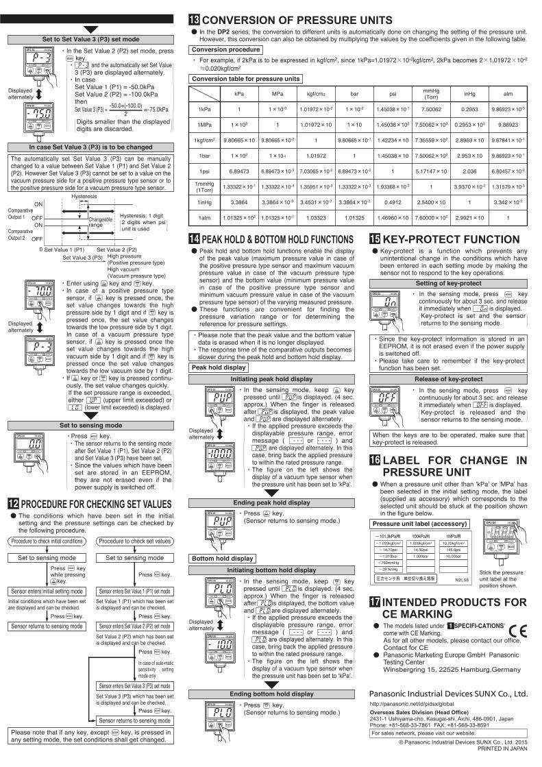
● In the DP2 series, the conversion to different units is automatically done on changing the setting of the pressure unit. However, this conversion can also be obtained by multiplying the values by the coefficients given in the following table.
・ For example, if 2kPa is to be expressed in kgf/cm2, since 1kPa=1.01972×10⁻²kgf/cm2, 2kPa becomes 2×1.01972×10-2 ≒0.020kgf/cm2
Conversion procedure
Conversion table for pressure units
1.01325×10² 1.01325×10⁻¹ 1.03323 1.01325 1.46960×10 7.60000×10² 2.9921×10 1
3.3864 3.3864×10⁻³ 3.4531×10⁻² 3.3864×10⁻² 0.4912 2.5400×10 1 3.342×10⁻²
1.33322×10⁻¹ 1.33322×10⁻⁴ 1.35951×10⁻³ 1.33322×10⁻³ 1.93368×10⁻² 1 3.9370×10⁻² 1.31579×10⁻³
6.89473 6.89473×10⁻³ 7.03065×10⁻² 6.89473×10⁻² 1 5.17147×10 2.036 6.80457×10⁻²
1×10² 1×10⁻¹ 1.01972 1 1.45038×10 7.50062×10² 2.953×10 9.86923×10⁻¹
9.80665×10 9.80665×10⁻² 1 9.80665×10⁻¹ 1.42234×10 7.35559×10² 2.8959×10 9.67841×10⁻¹
1×10³ 1 1.01972×10 1×10 1.45038×10² 7.50062×10³ 0.2953×10³ 9.86923
1 1×10⁻³ 1.01972×10⁻² 1×10⁻² 1.45038×10⁻¹ 7.50062 0.2953 9.86923×10⁻³
kPa MPa kgf/cm2 bar mmHg(Torr)
inHgpsi atm
1kPa
1MPa
1kgf/cm2
1bar
1mmHg(1Torr)
1inHg
1psi
1atm
CONVERSION OF PRESSURE UNITS13
● When a pressure unit other than 'kPa' or 'MPa' has been selected in the initial setting mode, the label (supplied as accessory) which corresponds to the selected unit should be stuck at the position shown in the figure below.
Pressure unit label (accessory) DP2-20 –101.3kPa
OUT2OUT1
MODE
0-ADJ
-1.033kgf/cm2
-101.3kPa用
-14.70psi
-1.013bar
-760mmHg
-29.9inHg
1.020kgf/cm2
100kPa用
14.50psi
1.000bar
10.20kgf/cm2
1MPa用
145.0psi
10.00bar
圧力センサ用 単位切り換え銘板 N2L58
Stick the pressure unit label at the position shown.
LABEL FOR CHANGE IN PRESSURE UNIT
16
● Key-protect is a function which prevents any unintentional change in the conditions which have been entered in each setting mode by making the sensor not to respond to the key operations.
・
・
Since the key-protect information is stored in an EEPROM, it is not erased even if the power supply is switched off.Please take care to remember if the key-protect function has been set.
Setting of key-protectDP2-20 -101.3kPa
OUT2OUT1
MODE
0-ADJ
・ In the sensing mode, press key continuously for about 3 sec. and release it immediately when is displayed.Key-protect is set and the sensor returns to the sensing mode.
MODE
When the keys are to be operated, make sure that key-protect is released.
Release of key-protect
・ In the sensing mode, press key continuously for about 3 sec. and release it immediately when is displayed.Key-protect is released and the sensor returns to the sensing mode.
MODEDP2-20 -101.3kPa
OUT2OUT1
MODE
0-ADJ
KEY-PROTECT FUNCTION15
●
●
The models listed under ' SPECIFI-CATIONS' come with CE Marking.As for all other models, please contact our office.Contact for CEPanasonic Marketing Europe GmbH Panasonic Testing CenterWinsbergring 15, 22525 Hamburg,Germany
1
INTENDED PRODUCTS FOR CE MARKING
17