Embed Size (px)
Citation preview

PH15 • 1
LED BARGRAPH / PEAK HOLD METER KIT
Ramsey Electronics Model No. PH15
Watch that power and don't blow out your favorite speakers! Unlike other bargraphs, this unit holds the peak display LED on a little longer - so you can easily chatch sharp peaks! Easily set to read AC, DC, power or voltage at virtually any level. Crank that stereo without the worry of damaging your speakers!
• Very versatile, can be set up to measure a number of different signals from DC to AC.
• Peak hold function - peaks your eyes normally can't detect can
easily be seen. • Attractive multicolored LED display for good visual indication of
level, even from across the room! • Can run off a wide range of voltages from 7V to 15V DC.
• Good companion with other Ramsey kits to monitor signal levels.
PH-16 for Semi-Log display Good for tape deck VU meters, mixer meters, etc.
PH-15 for Logarithmic display Good for power meters of all types (audio & RF).
PH-14 for Linear display Good for voltmeters, ammeters, general usage.

PH15 • 2
RAMSEY TRANSMITTER KITS • FM100B Professional FM Stereo Transmitter • FM25B Synthesized Stereo Transmitter • AM1, AM25 AM Transmitters • TV6 Television Transmitter RAMSEY RECEIVER KITS • FR1 FM Broadcast Receiver • AR1 Aircraft Band Receiver • SR2 Shortwave Receiver • AA7 Active Antenna • SC1 Shortwave Converter RAMSEY HOBBY KITS • SG7 Personal Speed Radar • SS70A Speech Scrambler • SP1 Speakerphone • WCT20 Wizard Cable Tracer • PH10 Peak hold Meter • BS1 “Bullshooter” Digital Voice Storage Unit • AVS10 Automatic Sequential Video Switcher • WCT20 Cable Wizard Cable Tracer • MD3 Microwave Motion Detector RAMSEY AMATEUR RADIO KITS • FX146 VHF Transceivers • HR Series HF All Mode Receivers • QRP Series HF CW Transmitters • CW7 CW Keyer • CPO3 Code Practice Oscillator • Packet Computer Interfaces • QRP Power Amplifiers RAMSEY MINI-KITS Many other kits are available for hobby, school, Scouts and just plain FUN. New kits are always under development. Write or call for our free Ramsey catalog.
PH15 PEAK HOLD METER KIT INSTRUCTION MANUAL
Ramsey Electronics publication No. MPH15 Revision 1.1 First printing: June 1993
COPYRIGHT 1993 by Ramsey Electronics, Inc. 590 Fishers Station Drive, Victor, New York 14564. All rights reserved. No portion of this publication may be copied or duplicated without the written permission of Ramsey Electronics, Inc. Printed in the United States of America.
PH15 • 3
PEAK HOLD / BARGRAPH METER
Ramsey Publication No. PH15 Price $5.00
TABLE OF CONTENTS Introduction to the PH15 ............... 4 How It Works ................................. 5 Parts List ....................................... 7 Tips and Notes .............................. 8 PH15 Assembly Instructions ......... 9 Setup and Calibration ................. 14 Customizing ................................. 15 Troubleshooting ........................... 17 Hints and Ideas ............................ 18 Parts Layout Diagram ................. 20 Schematic Diagram ..................... 21 Ramsey Kit Warranty .................. 22 Cutouts for Displays ..................... 23
KIT ASSEMBLY AND INSTRUCTION MANUAL FOR
RAMSEY ELECTRONICS, INC. 590 Fishers Station Drive
Victor, New York 14564 Phone (585) 924-4560
Fax (585) 924-4555

PH15 • 4
PH15 PEAK HOLD METER FEATURES: • Very versatile, can be set up to measure a number of different signals
from DC to AC. • Attractive multicolored LED display for good visual indication of level
even from across the room. • Entertaining to watch, a good attention grabber. • Peak hold function so peaks your eyes normally can't detect can easily
be seen. • Can run off a wide range of voltages from 7V to 15V DC. • Makes an excellent addition to any project that needs some form of
level indication. • Excellent for determining output wattage from stereos and musical
amps. • Good companion with the Ramsey FM-10 stereo transmitter to monitor
your input levels. • Can be used for: SWR meters, watt meters, volt meters, level
indicators, temperature indicators, VU meters, ect.
INTRODUCTION: The Ramsey PH15 is based around the popular LM3914 series LED bargraph display drivers. These drivers come in three styles; Linear (LM3914) - meaning each increment in the display is an equal change in input voltage (good for voltage meters). Semi-logarithmic (LM3916) - meaning each successive increment is less than the last (good for VU meters). And finally logarithmic (LM3915) - each successive step is double the last (good for power meters). There are two of these ICs in each kit, one for the left channel and one for the right. The peak hold function is performed by switching rapidly between two input stages that hold peaks, one with a short duration, and one with a long duration. The circuit that switches between the two peak hold sections also switches the LED bargraph drivers between bar and dot mode to get the floating dot effect.

PH15 • 5
CIRCUIT THEORY: Referring to your schematic diagram, you will see the basic layout of the circuit. You can see quite clearly the bargraph display drivers consisting of U3 and U4. These are what do most of the work in your circuit. They can be switched from a "bar" to a "dot" mode and we will take full advantage of this. Q1 allows the proper switching between the bar and dot modes that the straight output of U5 could not provide. U5 is a quad schmitt NAND gate. It is set up as an oscillator to provide a pair of approximately 500Hz square waves. One of the square waves is a mirror image of the other meaning the two signals are out of phase with each other. This allows alternating between two peak hold circuits using the 4066 quad bilateral switch (U2) while not allowing for both to be on at the same time. U1 a LM324 quad op amp is set up as four peak hold circuits, two for each channel. These peak hold circuits operate as a "real" diode. This means that there is no 0.7V drop on forward biasing as in a regular diode. The input is rectified into a DC signal through these real diodes, and sent directly into a capacitor. This capacitor holds the charge, but is slowly drawn off by a resistor in parallel with the capacitor, sort of like a small rechargeable battery. For each channel there is a long duration peak hold circuit, and a short duration peak hold circuit. It takes a little math to determine how long these peak hold signals take to decay. Notice the resistor and capacitor pair on the output of each op amp. The time constant for each circuit is determined by the formula T=R*C. For example the time constant for the long duration circuit is T = 1M * 1uF = 1 second. To find the voltage output after some time use the formula: Vout = Vinitial * exp(-time / T) For example if a 10 Volt pulse was applied to the input and then returned to zero, after one second of decay time the output should be: 10V * exp(-1sec /1sec) = 3.68 Volts As you can see, part values can be adjusted in this area to produce longer and shorter time of holding. A larger resistor or capacitor will increase the time for peak hold, and smaller values will decrease the time. The 4066 is an electronically operated switch that can quickly switch analog signals on and off. In this case they are switching between a long duration peak hold circuit and a short duration peak hold circuit on each channel. A long duration output is tied with a short duration output and sent to one of the

PH15 • 6
LED bargraph display drivers. Since the set of the bilateral switches on each channel are never on at the same time, the outputs can be tied together without any problems. When the long duration peak hold circuits are switched in, the LED drivers are switched into dot mode, and when the short duration peak hold circuits are switched in, the bar mode is selected. This is done fast enough so that the eye cannot see it.

PH15 • 7
PARTS SUPPLIED WITH THE PH-15 KIT CAPACITORS
1 .1uF disk capacitor (C5) 6 1uF electrolytic capacitor (C1, C2, C3, C4, C8, C9) 1 10uF electrolytic capacitor (C7) 1 100uF to 220uF electrolytic capacitor (C6)
RESISTORS
2 1M ohm (brown-black-green) (R4, R12) 3 100K ohm (brown-black-yellow) (R8, R16, R17) 6 10K ohm (brown-black-orange) (R1, R2, R5, R6, R9, R10, R13) 1 2K ohm (red-black-red) (R14) 2 1K ohm (brown-black-red) (R3, R11) 2 trimpots (R7, R15)
SEMICONDUCTORS
2 LM3915 LED bargraph display drivers (U3, U4) 1 4093 Quad schmitt trigger NAND gate (U5) 1 LM324 Quad opamp (U1) 1 4066 Quad bilateral switch (U2) 1 PNP transistor marked 221334, similar to 2N3906 (Q1) 4 1N4148 or equivalent small signal diodes (D4, D12, D15, D23) 20 (in all) assorted colored small LEDs (red,yellow,green) (D1, 2, 3, 5, 6, 7, 8, 9, 10, 11, 13, 14, 16, 17, 18, 19, 20, 21, 22, 24)
HARDWARE AND MISCELLANEOUS
2 RCA jacks (J1, J2) 1 Power jack (J3) 10" Bus wire for jumpers
OPTIONAL, NOT INCLUDED
Case and panels for that finished "PRO-LOOK" 7-15VDC plug in wall transformer

PH15 • 8
"THE RAMSEY LEARN AS YOU BUILD METER ASSEMBLY STRATEGY" As you can see by looking at the parts layout diagram, there is quite allot to the construction of the PH15. It's easier than it seems once you get going, and after you have place a few of the "landmark" components. Once these "landmark" components are placed, other part positions are referenced to them, and construction goes quite smoothly. We will consider the end of the board that has the jacks on it to be the back. In addition, we will discuss the purpose of most components or groups of components as we go along. This is the Ramsey Learn-As-You-Build kit assembly philosophy. Be sure to read through all the steps, and check the boxes as you go to be sure you didn't miss any important steps. Before you run the circuit, check all diodes and polarized capacitors for proper orientation. TIPS AND NOTES: Use a good soldering technique - let your soldering iron tip gently heat the traces to which you are soldering, heat both wires and pads simultaneously. Apply the solder on the iron, lead, and the pad when pad and wire are hot enough to melt the solder. The actual joint should look like a drop of water on paper, somewhat soaked in. Parts are mounted on the front of the boards. This is the side that has no traces or pads on it. IC sockets - a good practice in digital or low frequency circuits but is not required. This prevents the horror of placing ICs in the wrong way, and not easily being able to remove them. Part orientation - all parts in this kit are mounted at 90 degree angles. This means parts are either parallel or perpendicular to the sides of the board. Part installation - when parts are installed, the part is placed flat to the board, and the leads are bent on the backside of the board to prevent the part from falling out before soldering. The part is then soldered securely to the board, and then the remaining lead length is then clipped off.

PH15 • 9
CONSTRUCTION: Locate the larger of the two boards, we'll start assembling the larger board, since installing the LEDS on the smaller board will take some practice and patience.
1. Orient the circuit board as shown in the parts layout diagram.
2. Mount J1, J2, the RCA style jacks on the PC board. Note these may require some heat for the solder to flow cleanly onto your jacks. Be patient and take your time.
3. Install J3 the power jack.
4. You have just successfully installed the "landmark components" and these will guide you into further parts installation. Note at this point that you want to save all of your part's spare clipped off leads as these will be used for the many jumpers in this kit. We know that there are many jumpers in this kit, but to have opposing displays, this was necessary. Just think of them as zero ohm resistors (silver-silver-silver)!
5. Install C6, the 100uF to 220uF electrolytic capacitor. Electrolytic capacitors are polarized and must be installed correctly. They are usually marked with a black stripe and a ( - ) indicating their negative lead, while PC boards will usually indicate the ( + ) hole. Be careful as these will self-destruct if put in the wrong way!
6. We will not put in R5, R2, C8, R6, C9, and R9 at this point. We will save these to the end when we do our setup and calibration. Note where the holes are in reference to the other components on the board so that the next few parts will be installed correctly.
7. Install U5, the 4093 Quad schmitt NAND gate. Pay close attention to its orientation. Notice the tab, indent or line on one end of the IC, this indicates where pin one is. On your layout diagram, the semicircle on the end of the IC also represents this, and will be the case for all the IC's in this kit. Be careful soldering the leads so that you have no solder bridges.
8. Install C5, the .1uF (marked .1 or 104) ceramic capacitor. Notice the orientation of ceramic capacitors is not critical, unlike that of electrolytic capacitors.
9. Install R17, a 100K resistor (brown-black-yellow).
10. You have just completed the oscillator section of your kit! (easy step.)
11. With some spare lead or bus wire install JMP21. Jumpers act like

PH15 • 10
"bridges" over traces on the underside of the board. Construct a jumper by using a scrap of wire from a previously installed part.
12. Install R16, a 100K resistor (brown-black-yellow).
13. Install D23, a 1N4148 type small signal diode. Pay extra close attention to where the band is on the part. This band should be oriented in the same direction as what is shown in the board layout. If it is not your kit will not operate as desired
14. Install C4, a 1uF electrolytic capacitor. Pay close attention to its polarity!
15. Install JMP17 with some scrap clippings or bus wire.
16. Install R12, a 1M resistor (brown-black-green).
17. Install D15, another 1N4148 diode, watch orientation.
18. Install C3, a 1uF electrolytic capacitor. Again check polarity before soldering.
19. Install U1, the LM324 quad op amp. Make sure the notch is in the same orientation as the board layout.
20. Congratulations, you have just completed the peak hold circuits for the right channel.
21. Install JMP18 with some scrap wire.
22. Install JMP16.
23. Install R10, a 10K resistor (brown-black-orange).
24. Install U2, the 4066 quad bilateral switch. Pay close attention to its orientation.
25. Install JMP20, JMP10, and JMP11.
26. Install Q1, a 221334 type PNP transistor pay attention to its orientation as the larger flat side faces to the front of the board. Usually this flat side has the lettering on it, but is not always the case. Make sure the part is in the proper holes before soldering since there are many holes in that area of the board.
27. Install R1, a 10K resistor (brown-black-orange).
28. You have just completed the switching section of your peak hold meter that selects the long and short duration inputs, and the bar and dot modes of the LED display drivers.
29. Install D12, a 1N4148 type diode. Pay close attention to its orientation as it is opposite from earlier orientations.

PH15 • 11
30. Install R8, a 100K resistor (brown-black-yellow).
31. Install R4, a 1M resistor (brown-black-green).
32. Install D4, another 1N4148 type diode, check it's orientation.
33. Install C2 and C1, both 1uF electrolytic capacitors. Again pay close attention to their polarity.
34. Install C7, a 10uF electrolytic capacitor. This is used to filter out the AC noise created by toggling the dot and bar modes of the display.
35. Congratulations again, you have just completed the peak hold section for the left channel!
36. Install JMP12 with a piece of scrap wire.
37. Install R3, a 1K resistor (brown-black-red).
38. Install R7, one of the trimpots. After you are done installing it, use a small screwdriver to turn the adjustment in the center for later calibration.
39. Install JMP15.
40. For the remaining ICs, you may want to use IC sockets. You may want to replace the display driver with a different type for other applications at a later time.
41. Install U3, one of your LM3915 LED display driver chips. Pay close attention to the locating notch is before soldering.
42. You have just completed the driver for the Left channel.
43. Install R11, a 1K resistor (brown-black-red).
44. Install R15, the other small trimpot. R15 and R7 will be used to calibrate and scale your peak hold meter to your needs.
45. Install U4, the other LM3915 LED display driver chip.
46. Install JMP1, JMP2, JMP3, JMP4, JMP5, JMP6, JMP14, and finally JMP13. Use whatever scraps of wire you have left to do this, or else use some of your bus wire.
Congratulations, you have finished the right channel driver, along with completing the main board. Notice that you have not installed R2, R5, R6, R9, R13, R14, C8, and C9 at this point. Now it's time to complete the display board VERY CAREFULLY. This part of your kit takes some time and patience to get your display to be good looking and aligned. Don't be afraid to re-heat your solder joints to move the LEDs into alignment. Remember to be gentle, as you don't want to break the little guys, I'm sure if you are this far you don't want to wait for more LEDs! Remember that modern components
PH15 • 12
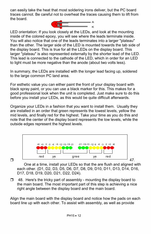
can easily take the heat that most soldering irons deliver, but the PC board traces cannot. Be careful not to overheat the traces causing them to lift from the board. LED orientation: If you look closely at the LEDs, and look at the mounting inside of the colored epoxy, you will see where the leads terminate inside. You will also notice that one of the leads terminates into a larger "plateau" than the other. The larger side of the LED is mounted towards the tab side of the display board. This is true for all the LEDs on the display board. This larger "plateau" is also represented externally by the shorter lead of the LED. This lead is connected to the cathode of the LED, which in order for an LED to light must be more negative than the anode (about two volts less). In summary, the LEDs are installed with the longer lead facing up, soldered to the large common PC land area. For esthetic value you can either paint the front of your display board with black spray paint, or you can use a black marker for this. This makes for a good professional look when the unit is completed. Just make sure to do this before you install your LEDs, as this would be quite difficult afterwards. Organize your LEDs in a fashion that you want to install them. Usually they are installed in an order that green represents the lowest levels, yellow the mid levels, and finally red for the highest. Take your time as you do this and note that the center of the display board represents the low levels, while the outside edges represent the highest levels.
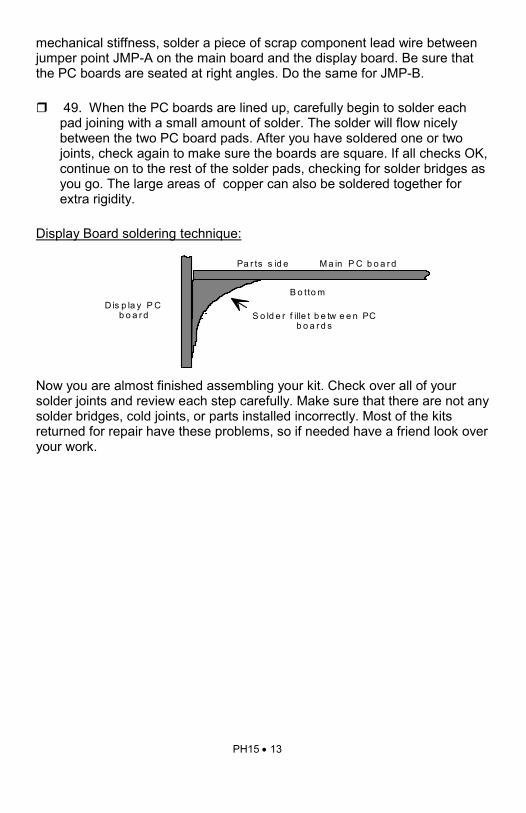
47. One at a time, install your LEDs so that the are flush and aligned with each other. (D1, D2, D3, D5, D6, D7, D8, D9, D10, D11, D13, D14, D16, D17, D18, D19, D20, D21, D22, D24).
48. Here's the tricky part of assembly - mounting the display board to the main board. The most important part of this step is achieving a nice right angle between the display board and the main board.
Align the main board with the display board and notice how the pads on each board line up with each other. To assist with assembly, as well as provide
A
K
+ 3 0 - 3 - 6 - 9 - 1 2 - 1 5 - 1 8 - 2 1 + 6 + 3 0 - 3 - 6 - 9 - 1 2 - 1 5 - 1 8 - 2 1 + 6
red yel
gree yel
red
PH15 • 13
mechanical stiffness, solder a piece of scrap component lead wire between jumper point JMP-A on the main board and the display board. Be sure that the PC boards are seated at right angles. Do the same for JMP-B.
49. When the PC boards are lined up, carefully begin to solder each pad joining with a small amount of solder. The solder will flow nicely between the two PC board pads. After you have soldered one or two joints, check again to make sure the boards are square. If all checks OK, continue on to the rest of the solder pads, checking for solder bridges as you go. The large areas of copper can also be soldered together for extra rigidity.
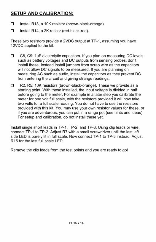
Display Board soldering technique: Now you are almost finished assembling your kit. Check over all of your solder joints and review each step carefully. Make sure that there are not any solder bridges, cold joints, or parts installed incorrectly. Most of the kits returned for repair have these problems, so if needed have a friend look over your work.
M a in P C b o a r d
D is p la y P C b o a r d S o ld e r f ille t b e tw e e n PC
b o a r d s
Pa r ts s id e
B o tto m
PH15 • 14
SETUP AND CALIBRATION:
Install R13, a 10K resistor (brown-black-orange).
Install R14, a 2K resitor (red-black-red). These two resistors provide a 2VDC output at TP-1, assuming you have 12VDC applied to the kit.
C8, C9: 1uF electrolytic capacitors. If you plan on measuring DC levels such as battery voltages and DC outputs from sensing probes, don't install these. Instead install jumpers from scrap wire as the capacitors will not allow DC signals to be measured. If you are planning on measuring AC such as audio, install the capacitors as they prevent DC from entering the circuit and giving strange readings.
R2, R5: 10K resistors (brown-black-orange). These we provide as a starting point. With these installed, the input voltage is divided in half before going to the meter. For example in a later step you calibrate the meter for one volt full scale, with the resistors provided it will now take two volts for a full scale reading. You do not have to use the resistors provided with this kit. You may use your own resistor values for these, or if you are adventurous, you can put in a range pot (see hints and ideas). For setup and calibration, do not install these yet.
Install single short leads in TP-1, TP-2, and TP-3. Using clip leads or wire, connect TP-1 to TP-2. Adjust R7 with a small screwdriver until the last left side LED is barely lit in full scale. Now connect TP-1 to TP-3 instead. Adjust R15 for the last full scale LED. Remove the clip leads from the test points and you are ready to go!

PH15 • 15
CUSTOMIZING: Now here is where we deal with R2, R5, R6, R9, C8, and C9. This is an opportunity to make your own design choices. To Find R2 and R5 for a desired full scale reading: V Full scale wanted = ((R2 + R5) * V Full scale of meter) / R5 Input load resistance (impedance) = R2 + R5 Use R2 + R5 between 20K and 500K depending on the input resistance desired. EX: You want to have a full scale reading of 13.8 volts DC with an input impedance of 50,000 ohms and you want your meter to be internally calibrated at around 2 volts full scale. 1. Since the voltage you are measuring is DC install jumpers in place of C8
and C9. This allows the DC input voltage to go directly to R2 and R6. 2. R2 + R5 = 50,000 ohms 3. Volts = (50,000 ohms * 2 volts) / R5 4. Rearranging: R5 = (50,000 ohms * 2 volts) / 13.8 5. Which is: R5 = 7,246 ohms 6. Since the closest 5% resistor value is 6,800 ohms we will use that
instead. 7. Since R2 + R5 = 50,000; R2 + 6,800 = 50,000 8. Rearranging this we get: R2 = 50,000 - 6,800 9. Which is: R2 = 43,200 10. The closest 5% value for this is 47,000 ohms 11. Now with the two values found for our resistors we must recalculate the
main formula to find what the new full scale voltage we need to adjust the meter for.
12. Volts = ((6,800 + 47,000) * V Full scale meter) / 6,800 13. Rearranging: V Full scale meter = (13.8 volts * 6,800) / ( 6,800 + 47,000)

PH15 • 16
14. Which is: V Full scale meter = 1.74 volts 15. Now you would re-calibrate your meter for 1.74 volts full scale to
represent the 13.8 volts full scale. The same calculations are used for AC voltages. Use peak voltage, not RMS or peak to peak. Also install C8 and C9. To find R5 and R2, which are provided as 10K resistors (brown-black-orange). The same is true for these resistors as in the previous calculations. Only replace R5 with R9, and R2 with R6 in the formulas. If you want both left and right meters to respond equally to the same levels, just make R9 = R5, and R6 = R2. Now calibrate both sides in the same manner. Radio Shack or a local electronics surplus store is good for finding the resistor values that you need.

PH15 • 17
TROUBLESHOOTING TIPS: If you have problems with your Ramsey Kit, check all of your work very thoroughly. Go through all the steps and make sure you have completed them all. Most of the kits we repair have assembly mistakes, or something simple that was overlooked by the builder. Have a friend check your work, this helps since they may see what you do not. PROBLEM: One or more of the LEDs will not light between LEDs that do light. SOLUTION: Check the orientation of the LEDs, see the LED orientation information in this manual. If that is OK, check from the LED back to the display driver for possible solder bridges or cold solder joints. If it is necessary, use a continuity checker to test for a connection. If that is OK, you may have a defective LED, this unfortunately occurs sometimes. Call Ramsey Electronics and we will be happy to help you with this problem. PROBLEM: Your meter will not full scale at the full scale voltage desired. SOLUTION: Choose a lower full scale voltage. PROBLEM: The meter only shows bar or dot display but not both. SOLUTION: This is a symptom of the oscillator section of the circuit not operating. Check around U5 for solder bridges and cold joints. Also check Q1 for orientation. Check pin 4 of U5 and the center lead of Q1 for approximately 60Hz - 400Hz of square wave signal. If the signal is not present, check for the source voltage on pin 14. If the signal is present, check all traces leaving U5 for solder bridges. If everything is still OK, send your kit in, U5 may be bad or installed incorrectly. PROBLEM: One or more of the peak hold sections does not respond to input. SOLUTION: Check around U1 for assembly errors. Make sure D15, D23, D4, and D12 are oriented as shown in the parts layout. Also check C3, C4, C1, and C2 for orientation. PROBLEM: The whole left side or the whole right side will not work. SOLUTION: Check around U4 and U3 for appropriate voltages. With a signal applied, check pin 5 of both for some voltage. This is the input pin of the ICs, if there is nothing there, check around U1 for problems (see previous problem). If there is voltage on pin 5, rotate R7 and R15 across their ranges to observe any changes. Also you can check for supply voltage on pin 3 of both ICs. If none of this works, check LED orientations and solder joints. PROBLEM: Everything seems to be working, but the display is always in bar or dot mode. SOLUTION: Check Q1 and connections leading from it for assembly errors.
PH15 • 18
PROBLEM: The darned thing just won’t work! SOLUTION: See the Ramsey kit warranty information in the manual. The same people who designed the kit will more than likely be fixing it for you. USING YOUR PH15 After you have followed all the assembly instructions, and your unit is fully calibrated and tested, it couldn't be simpler to use. Simply plug your signal to be measured into the appropriate jacks on the back of your kit, plug in the power using a plug in the wall supply and watch. Be carefull and use your good judgement when connecting your meter up, as we don't wish you to cause problems with this fun to build and use Ramsey kit! HINTS AND IDEAS: Using your imagination and some of the free space on the back of the kit, you can do a number of things to enhance your kit, such as range switches, add a power switch, range adjustment potentiometers, etc. You can also add a label to your PH15 kit which will show the levels that your meter is indicating. Use an exacto knife or scissors to cut one of the labels in the back of the manual out, and then tape or glue it to the display of your peak hold meter. To use your kit as a replacement for conventional meter movements, all you need to do is calibrate your meter for full scale voltage that was the same for the meter movement, and calculate your part values for the meter impedance that was required. For example, a 1mA full scale meter with 10K ohms of resistance would be replaced by your meter calibrated for 1mA * 10K ohms = 10 Volts full scale with a 10K ohm input impedance. Just make sure to use a floating non-grounded power supply or battery for the kit to prevent grounding problems with your equipment. Steps for installing a power switch Use a small panel mount switch available at Radio Shack or similar store, for example a single pole, single throw switch. 1. Cut the small trace between the pads marked SW-1 and SW-2 on your
layout diagram. 2. Wire one side of your switch from the hole marked SW-1, and the other
side to the hole marked SW-2 3. Mount the switch to the case, or wherever you desire.

PH15 • 19
Using your PH15 as an audio power meter: Note: this is calibrated to a full scale voltage of 2V. Pmax = 1Watt: Rin = 50K
Pmax = 10Watts: Rin = 50K Pmax = 100Watts: Rin = 50K Pmax = 200Watts: Rin = 50K
Speaker R2 R6 R5 R9 16Ω 25K 25K 25K 25K
8Ω 15K 15K 33K 33K
4Ω jumper jumper 47K 47K
Speaker R2 R6 R5 R9 16Ω 47K 47K 8.2K 8.2K
8Ω 33K 33K 10K 10K
4Ω 33K 33K 15K 15K
Speaker R2 R6 R5 R9 16Ω 47K 47K 2.7K 2.7K
8Ω 47K 47K 3.3K 3.3K
4Ω 47K 47K 4.7K 4.7K
Speaker R2 R6 R5 R9 16Ω 47K 47K 1.8K 1.8K
8Ω 47K 47K 2.7K 2.7K
4Ω 47K 47K 3.3K 3.3K

PH15 • 20
PH15 PARTS LAYOUT DIAGRAM

PH15 • 21

PH15 • 22
The Ramsey Kit Warranty Please read carefully BEFORE calling or writing in about your kit. Most problems can be solved without contacting the factory. Notice that this is not a "fine print" warranty. We want you to understand your rights and ours to! All Ramsey kits will work if assembled properly. The very fact that your kit includes this new manual is your assurance that a team of knowledgeable people have field-tested several "copies" of this kit straight from the Ramsey Inventory. If you need help, please read through your manual carefully, all information required to properly build and test your kit is contained within the pages! 1. DEFECTIVE PARTS: It's always easy to blame a part for a problem in your kit, Before you conclude that a part may be bad, thoroughly check your work. Today's semiconductors and passive components have reached incredibly high reliability levels, and it’s sad to say that our human construction skills have not! But on rare occasion a sour component can slip through. All our kit parts carry the Ramsey Electronics Warranty that they are free from defects for a full ninety (90) days from the date of purchase. Defective parts will be replaced promptly at our expense. If you suspect any part to be defective, please mail it to our factory for testing and replacement. Please send only the defective part(s), not the entire kit. The part(s) MUST be returned to us in suitable condition for testing. Please be aware that testing can usually determine if the part was truly defective or damaged by assembly or usage. Don't be afraid of telling us that you 'blew-it', we're all human and in most cases, replacement parts are very reasonably priced. 2. MISSING PARTS: Before assuming a part value is incorrect, check the parts listing carefully to see if it is a critical value such as a specific coil or IC, or whether a RANGE of values is suitable (such as "100 to 500 uf"). Often times, common sense will solve a mysterious missing part problem. If you're missing five 10K ohm resistors and received five extra 1K resistors, you can pretty much be assured that the '1K ohm' resistors are actually the 'missing' 10 K parts ("Hum-m-m, I guess the 'red' band really does look orange!") Ramsey Electronics project kits are packed with pride in the USA. If you believe we packed an incorrect part or omitted a part clearly indicated in your assembly manual as supplied with the basic kit by Ramsey, please write or call us with information on the part you need and proof of kit purchase 3. FACTORY REPAIR OF ASSEMBLED KITS: To qualify for Ramsey Electronics factory repair, kits MUST:
1. NOT be assembled with acid core solder or flux. 2. NOT be modified in any manner. 3. BE returned in fully-assembled form, not partially assembled. 4. BE accompanied by the proper repair fee. No repair will be undertaken until we have received the MINIMUM repair fee (1/2 hour labor) of $25.00, or authorization to charge it to your credit card account. 5. INCLUDE a description of the problem and legible return address. DO NOT send a separate letter; include all correspondence with the unit. Please do not include your own hardware such as non-Ramsey cabinets, knobs, cables, external battery packs and the like. Ramsey Electronics, Inc., reserves the right to refuse repair on ANY item in which we find excessive problems or damage due to construction methods. To assist customers in such situations, Ramsey Electronics, Inc., reserves the right to solve their needs on a case-by-case basis.
The repair is $50.00 per hour, regardless of the cost of the kit. Please understand that our technicians are not volunteers and that set-up, testing, diagnosis, repair and repacking and paperwork can take nearly an hour of paid employee time on even a simple kit. Of course, if we find that a part was defective in manufacture, there will be no charge to repair your kit (But please realize that our technicians know the difference between a defective part and parts burned out or damaged through improper use or assembly). 4. REFUNDS: You are given ten (10) days to examine our products. If you are not satisfied, you may return your unassembled kit with all the parts and instructions and proof of purchase to the factory for a full refund. The return package should be packed securely. Insurance is recommended. Please do not cause needless delays, read all information carefully.

PH15 • 23
9 8 7 6 5 4 3 2 110 987654321 10
+3 0 -3 -6 -9 -12 -15 -18 -21+6 +30-3-6-9-12-15-18-21 +6
+3 +2 +1 0 -1 -3 -5 -7 -10 -20 +3+2+10-1-3-5-7-10-20
5 2.5 1.3 .65 .33.16 .08 .04 .0210 52.5.65.33.16.08.04.02 101.3
100 50 25 13 6.2 3.1 1.5 .8 .4200 1005025136.23.11.5.8.4 200
50 25 13 6.5 3.3 1.6 .8 .4 .2100 5025136.53.31.6.8.4.2 100
Log display for LM3915
Linear display for LM3914
Semi-Logrithmic display for LM3916
10 Watt Display for LM3915
100 Watt Display for LM3915
200 Watt Display for LM3915

PH15 • 24
PH15 PEAK HOLD METER Quick Reference Page Guide
Introduction to the PH15 ................... 4 How It Works .................................... 5 Parts List ........................................... 7 PH15 Assembly Instructions ............. 9 Customizing ......................................15 Troubleshooting ................................17 Hints and Ideas .................................18 Parts Layout Diagram .......................20 Schematic Diagram ..........................21
Price: $5.00 Ramsey Publication No. MPH15 Assembly and Instruction manual for: RAMSEY MODEL NO. PH15 PEAK HOLD METER KIT
RAMSEY ELECTRONICS, INC. 590 Fishers Station Drive Victor, New York 14564 Phone (585) 924-4560 Fax (585) 924-4555 www.ramseykits.com
REQUIRED TOOLS • Soldering Iron Ramsey WLC100 • Thin Rosin Core Solder Ramsey RTS12 • Needle Nose Pliers Ramsey MPP4 or RTS05 • Small Diagonal Cutters Ramsey RTS04 <OR> Technician’s Tool Kit TK405 ADDITIONAL SUGGESTED ITEMS • Holder for PC Board/Parts Ramsey HH3 • Desoldering Braid Ramsey RTS08 • Digital Multimeter Ramsey M133