Embed Size (px)
Citation preview

CHAPTER 8 MIMO Xijun Wang

WEEKLY READING
1. Goldsmith, “Wireless Communications”, Chapters10
2. Tse, “Fundamentals of Wireless Communication”,Chapter 7-10
2

MIMO TRANSCEIVER
3

MIMO TRANSCEIVER
n Encoding¨ Mapping one data stream to one or more spatial data
streams.¨ Assumes no CSIT and focuses on enhancing reliability
through diversity.
n Precoding¨ Mapping the spatial data streams to the transmit
antennas.¨ Exploits the channel information available at the
transmitter and focuses on enhancing system performance.
4
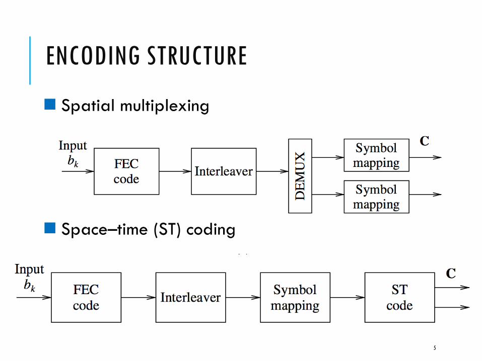
ENCODING STRUCTURE
n Spatial multiplexing
n Space–time (ST) coding
5

SPATIAL MULTIPLEXING
n Vertical encoding Bell Labs Layered Space Time (BLAST) architecture
6
the data stream is demultiplexedinto Mt independent streams
achieve at most a diversity order of Mr
transmite the independent codewords on separate antennas

SPATIAL MULTIPLEXING
n Diagonal encoding Bell Labs Layered Space Time (BLAST) architecture
7
the data stream is first horizontally encoded
the codeword symbols are rotated across antennas

SPATIAL MULTIPLEXING
n D-BLAST
8
a codeword is spread over all Mt antennas
achieve the full MtMr diversity gain

SPACE-TIME CODING
n Space–time coding (STC) scheme¨ introduce temporal and spatial correlation into the
signals transmitted from different antennas ¨ without increasing the total transmitted power or the
transmission bandwidth.
n A diversity gain that results from multiple paths between the base-station and the user terminal
n A coding gain that results from how symbols are correlated across transmit antennas
9

SPACE–TIME CODE DESIGN CRITERIA
n Pairwise error probability ¨ the probability that an erroneous codeword e is
mistaken for the transmitted codeword x.
¨ q denotes the rank of A(x,e).¨ 𝜆n are the eigenvalues of the matrix A(x,e).¨
10

SPACE–TIME CODE DESIGN CRITERIA
n Rank criterion¨ In order to achieve maximum diversity Mt Mr , the
matrix B(x,e) has to be full rank for any codewords x, e. ¨ If the minimum rank of B(x,e) over all pairs of distinct
codewords is q, then a diversity order of qMr is achieved.
n Determinant criterion. ¨ For a given diversity order target of q, maximize
over all pairs of distinct codewords.
11

SPACE–TIME TRELLIS CODES (STTC)
n The space–time trellis encoder maps the information bit stream into Mt streams of symbols (each belonging in a size-2b signal constellation) that are transmitted simultaneously.
n The total transmitted power is divided equally among the Mt transmit antennas.
n The decoding complexity of STTC (measured by the number of trellis states at the decoder) increases exponentially as a function of the diversity level and the transmission rate
12

EIGHT-STATE 8PSK STTC WITH TWO ANTENNAS
13Tx1
Tx2

EIGHT-STATE 4PSK STTC WITH TWO ANTENNAS
14
Input: 0 1 2 3 2 1State:0

SPACE–TIME BLOCK CODES (STBC)
n Alamouti’s codes¨ First, it achieves full-diversity at full transmission rate for
any (real or complex) signal constellation. ¨ Second, it does not require CSI at the transmitter (i.e.
open-loop). ¨ Third, maximum-likelihood decoding involves only linear
processing at the receiver (due to the orthogonal code structure).
n Extensions¨ full-rate orthogonal designs exist for all real
constellations for two, four, and eight transmit antennas only,
¨ for all complex constellations they exist only for two transmit antennas (the Alamouti scheme).
15

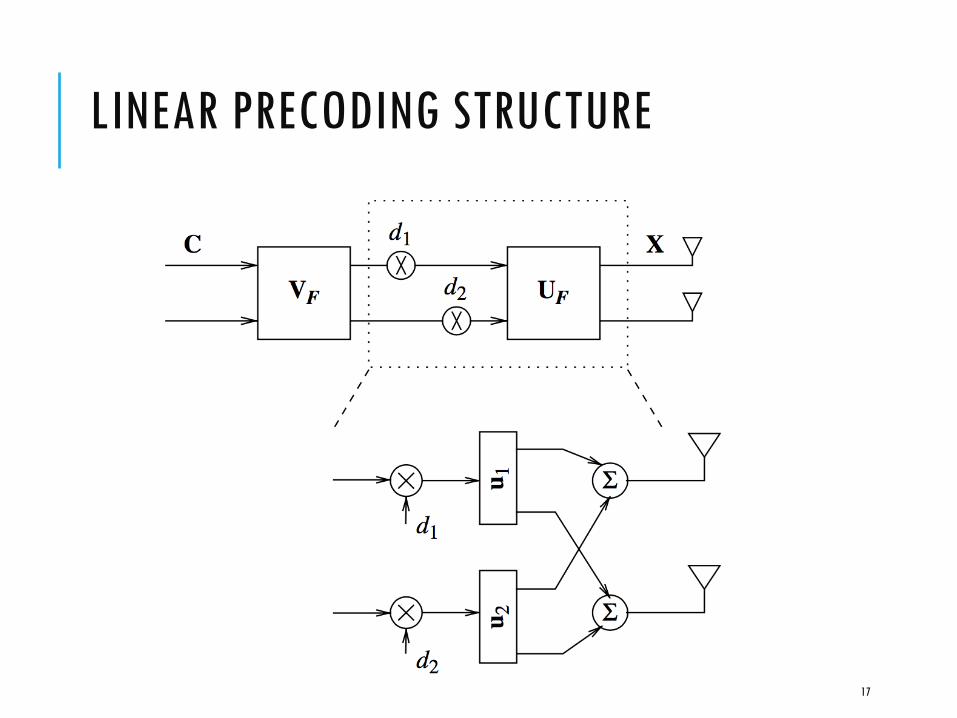
LINEAR PRECODING STRUCTURE
n A linear precoder functions as an input shaper and a beamformer with one or multiple beams with per-beam power allocation.
n Consider the singular value decomposition of the precoder matrix F
¨ orthogonal beam directions (patterns) are the left singular vectors UF
¨ the beam power loadings are the squared singular values D2
¨ The right singular vectors VF , termed the input shaping matrix
16
LINEAR PRECODING STRUCTURE
17

LINEAR PRECODING STRUCTURE
n A precoder therefore has two effects¨ decoupling the input signal into orthogonal spatial
modes in the form of eigen-beams¨ allocating power over these beams, based on the CSIT.
n If the precoded orthogonal spatial modes match the channel eigen-directions, there will be no interference among signals sent on these modes, creating parallel channels and allowing transmission of independent signal streams.
18

LINEAR PRECODING STRUCTURE
n For orthogonal eigen-beams, if the beams all have equal power, the radiation pattern of the transmit antenna array is isotropic.
n If the beam powers are different, however, the overall transmit radiation pattern will have a specific shape.
19

RECEIVER ARCHITECTURES
n joint ML decoding of the data streams ¨ the complexity grows exponentially with the number of
data streams.
n use linear operations to convert the problem of joint decoding of the data streams into one of individual decoding of the data streams
20

LINEAR DECORRELATOR
21
if there are more data streams than the dimension of the received signal (i.e., nt > nr), then the decorrelator operation will not be successful
remove this inter-stream interference is to project the received signal y onto the subspace orthogonal to the one spanned by the vectors
the decorrelator for the kth stream is the kth column of the pseudoinverse H† of the matrix H

SUCCESSIVE CANCELLATION
n the result of one of the filters could be used to aid the operation of the others.
n once a data stream is successfully recovered, we can subtract it off from the received vector and reduce the burden on the receivers of the remaining data streams.
n error propagation: an error in decoding the kth data stream means that the subtracted signal is incorrect and this error propagates to all the streams further down, k +1, . . . , nt .
22

DECORRELATOR-SIC
23

DECORRELATOR-SIC
n At high SNR, for i.i.d. Rayleigh fading, the basic decorrelator bank achieves the full degrees of freedom in the channel.
n Successive cancellation does not provide additional degrees of freedom.
n There is a power gain: by decoding and subtracting instead of linear nulling, the effective SNR at each stage is improved.
24

MMSE RECEIVER
n decorrelator¨ completely eliminating inter-stream interference ¨ without any regard to how much energy of the stream
of interest is lost in this process
n matched filtering ¨ preserving as much energy content of the stream of
interest as possible ¨ at the cost of possibly facing high inter-stream
interference
25

MMSE RECEIVER
26

MMSE RECEIVER
n At high SNR¨ the inter-stream interference is dominant over the
additive Gaussian noise and the decorrelator performs well.
n At low SNR ¨ the inter-stream interference is not as much of an issue
and receive beamforming (matched filter) is the superior strategy.
¨ In fact, the bank of matched filters achieves capacity at low SNR
27

MMSE RECEIVER
n Linear MMSE receiver
n Low SNR
n High SNR
n Output SINR
28

MMSE RECEIVER
29

MMSE-SIC
30

MMSE-SIC
31
The bank of linear MMSE receivers with successive cancellation and equal power allocation achieves the capacity of the i.i.d. Rayleigh fading channel.